Embed Size (px)
Citation preview
3.D.1 Printing
EMEP/EEA emission inventory guidebook 2009 1
Coordinator Jeroen Kuenen & Carlo Trozzi Contributing authors (including to earlier versions of this chapter) Mike Woodfield
Category Title
NFR: 3.D.1 Printing
SNAP: 060403 Printing industry
ISIC:
Version Guidebook 2009
3.D.1 Printing
EMEP/EEA emission inventory guidebook 2009 2
Contents 1 Overview...................................................................................................................................3 2 Description of sources...............................................................................................................3
2.1 Process description ..............................................................................................................3 2.2 Techniques ..........................................................................................................................4 2.3 Emissions ............................................................................................................................6 2.4 Controls ...............................................................................................................................8
3 Methods...................................................................................................................................10 3.1 Choice of method ..............................................................................................................10 3.2 Tier 1 Default Approach....................................................................................................10 3.3 Tier 2 technology-specific approach .................................................................................12 3.4 Tier 3 emission modelling and use of facility data............................................................17
4 Data quality.............................................................................................................................17 4.1 Completeness ....................................................................................................................17 4.2 Avoiding double counting with other sectors....................................................................17 4.3 Verification........................................................................................................................18 4.4 Developing a consistent time series and recalculation ......................................................19 4.5 Uncertainty assessment .....................................................................................................19 4.6 Inventory quality assurance/quality control QA/QC .........................................................19 4.7 Gridding ............................................................................................................................20 4.8 Reporting and documentation............................................................................................20
5 Glossary ..................................................................................................................................20 6 References...............................................................................................................................21 7 Point of enquiry.......................................................................................................................22
3.D.1 Printing
EMEP/EEA emission inventory guidebook 2009 3
1 Overview The printing industry is an important manufacturing industry in most European countries. Printing processes convert original text and pictures into an image on a carrier and the main process types are named according to how this image is carried. The main processes in the printing industry are described in the process description. In this document, the following printing categories are identified:
• heat set offset printing
• publication packaging
• rotogravure and flexography
.
2 Description of sources
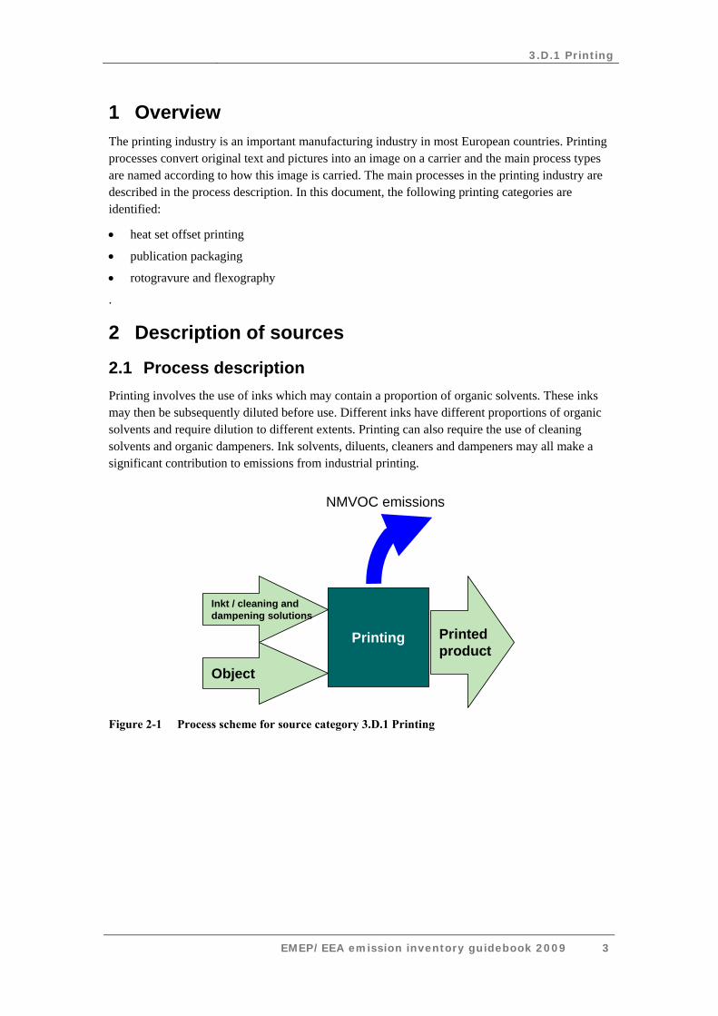
2.1 Process description Printing involves the use of inks which may contain a proportion of organic solvents. These inks may then be subsequently diluted before use. Different inks have different proportions of organic solvents and require dilution to different extents. Printing can also require the use of cleaning solvents and organic dampeners. Ink solvents, diluents, cleaners and dampeners may all make a significant contribution to emissions from industrial printing.
Printed product
NMVOC emissions
Printing
Inkt / cleaning and dampening solutions
Object
Figure 2-1 Process scheme for source category 3.D.1 Printing
3.D.1 Printing
EMEP/EEA emission inventory guidebook 2009 4
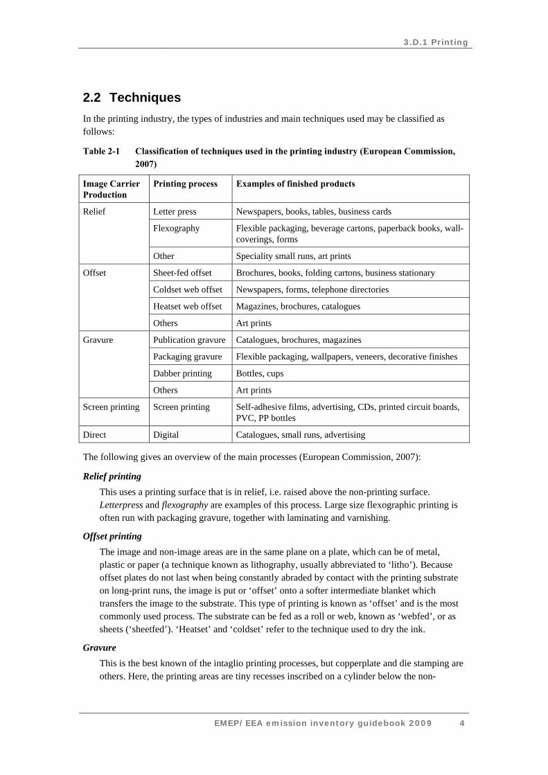
2.2 Techniques In the printing industry, the types of industries and main techniques used may be classified as follows:
Table 2-1 Classification of techniques used in the printing industry (European Commission, 2007)
Image Carrier Production
Printing process Examples of finished products
Letter press Newspapers, books, tables, business cards
Flexography Flexible packaging, beverage cartons, paperback books, wall-coverings, forms
Relief
Other Speciality small runs, art prints
Sheet-fed offset Brochures, books, folding cartons, business stationary
Coldset web offset Newspapers, forms, telephone directories
Heatset web offset Magazines, brochures, catalogues
Offset
Others Art prints
Publication gravure Catalogues, brochures, magazines
Packaging gravure Flexible packaging, wallpapers, veneers, decorative finishes
Dabber printing Bottles, cups
Gravure
Others Art prints
Screen printing Screen printing Self-adhesive films, advertising, CDs, printed circuit boards, PVC, PP bottles
Direct Digital Catalogues, small runs, advertising
The following gives an overview of the main processes (European Commission, 2007):
Relief printing This uses a printing surface that is in relief, i.e. raised above the non-printing surface. Letterpress and flexography are examples of this process. Large size flexographic printing is often run with packaging gravure, together with laminating and varnishing.
Offset printing The image and non-image areas are in the same plane on a plate, which can be of metal, plastic or paper (a technique known as lithography, usually abbreviated to ‘litho’). Because offset plates do not last when being constantly abraded by contact with the printing substrate on long-print runs, the image is put or ‘offset’ onto a softer intermediate blanket which transfers the image to the substrate. This type of printing is known as ‘offset’ and is the most commonly used process. The substrate can be fed as a roll or web, known as ‘webfed’, or as sheets (‘sheetfed’). ‘Heatset’ and ‘coldset’ refer to the technique used to dry the ink.
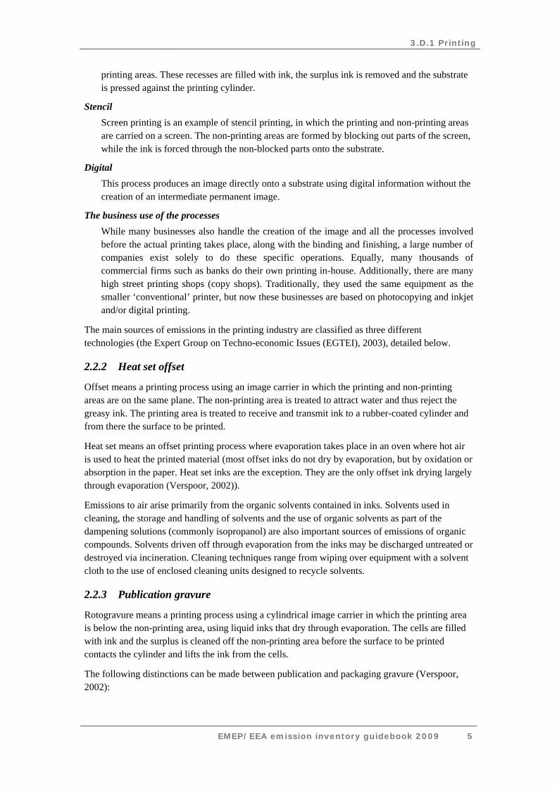
Gravure This is the best known of the intaglio printing processes, but copperplate and die stamping are others. Here, the printing areas are tiny recesses inscribed on a cylinder below the non-
3.D.1 Printing
EMEP/EEA emission inventory guidebook 2009 5
printing areas. These recesses are filled with ink, the surplus ink is removed and the substrate is pressed against the printing cylinder.
Stencil Screen printing is an example of stencil printing, in which the printing and non-printing areas are carried on a screen. The non-printing areas are formed by blocking out parts of the screen, while the ink is forced through the non-blocked parts onto the substrate.
Digital This process produces an image directly onto a substrate using digital information without the creation of an intermediate permanent image.
The business use of the processes While many businesses also handle the creation of the image and all the processes involved before the actual printing takes place, along with the binding and finishing, a large number of companies exist solely to do these specific operations. Equally, many thousands of commercial firms such as banks do their own printing in-house. Additionally, there are many high street printing shops (copy shops). Traditionally, they used the same equipment as the smaller ‘conventional’ printer, but now these businesses are based on photocopying and inkjet and/or digital printing.
The main sources of emissions in the printing industry are classified as three different technologies (the Expert Group on Techno-economic Issues (EGTEI), 2003), detailed below.
2.2.2 Heat set offset
Offset means a printing process using an image carrier in which the printing and non-printing areas are on the same plane. The non-printing area is treated to attract water and thus reject the greasy ink. The printing area is treated to receive and transmit ink to a rubber-coated cylinder and from there the surface to be printed.
Heat set means an offset printing process where evaporation takes place in an oven where hot air is used to heat the printed material (most offset inks do not dry by evaporation, but by oxidation or absorption in the paper. Heat set inks are the exception. They are the only offset ink drying largely through evaporation (Verspoor, 2002)).
Emissions to air arise primarily from the organic solvents contained in inks. Solvents used in cleaning, the storage and handling of solvents and the use of organic solvents as part of the dampening solutions (commonly isopropanol) are also important sources of emissions of organic compounds. Solvents driven off through evaporation from the inks may be discharged untreated or destroyed via incineration. Cleaning techniques range from wiping over equipment with a solvent cloth to the use of enclosed cleaning units designed to recycle solvents.
2.2.3 Publication gravure
Rotogravure means a printing process using a cylindrical image carrier in which the printing area is below the non-printing area, using liquid inks that dry through evaporation. The cells are filled with ink and the surplus is cleaned off the non-printing area before the surface to be printed contacts the cylinder and lifts the ink from the cells.
The following distinctions can be made between publication and packaging gravure (Verspoor, 2002):
3.D.1 Printing
EMEP/EEA emission inventory guidebook 2009 6
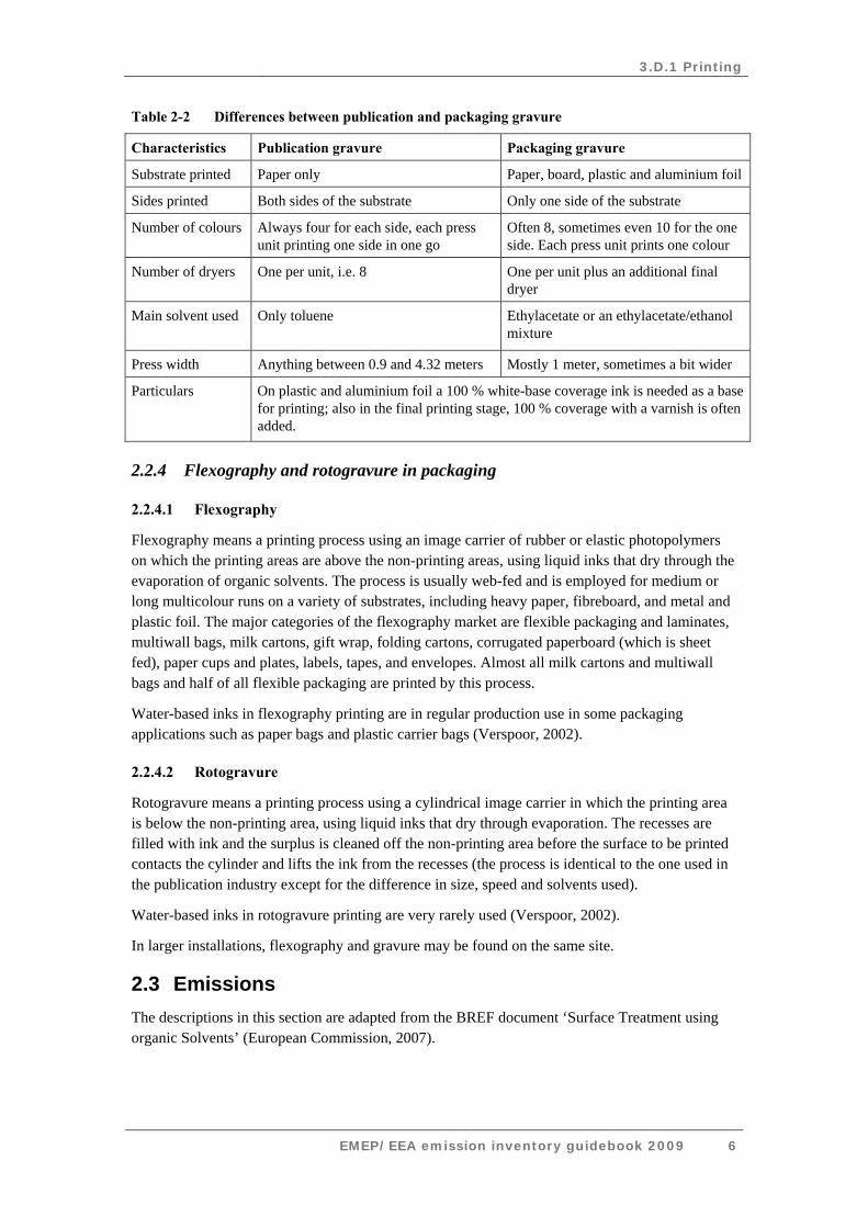
Table 2-2 Differences between publication and packaging gravure
Characteristics Publication gravure Packaging gravure
Substrate printed Paper only Paper, board, plastic and aluminium foil
Sides printed Both sides of the substrate Only one side of the substrate
Number of colours Always four for each side, each press unit printing one side in one go
Often 8, sometimes even 10 for the one side. Each press unit prints one colour
Number of dryers One per unit, i.e. 8 One per unit plus an additional final dryer
Main solvent used Only toluene Ethylacetate or an ethylacetate/ethanol mixture
Press width Anything between 0.9 and 4.32 meters Mostly 1 meter, sometimes a bit wider
Particulars On plastic and aluminium foil a 100 % white-base coverage ink is needed as a base for printing; also in the final printing stage, 100 % coverage with a varnish is often added.
2.2.4 Flexography and rotogravure in packaging
2.2.4.1 Flexography
Flexography means a printing process using an image carrier of rubber or elastic photopolymers on which the printing areas are above the non-printing areas, using liquid inks that dry through the evaporation of organic solvents. The process is usually web-fed and is employed for medium or long multicolour runs on a variety of substrates, including heavy paper, fibreboard, and metal and plastic foil. The major categories of the flexography market are flexible packaging and laminates, multiwall bags, milk cartons, gift wrap, folding cartons, corrugated paperboard (which is sheet fed), paper cups and plates, labels, tapes, and envelopes. Almost all milk cartons and multiwall bags and half of all flexible packaging are printed by this process.
Water-based inks in flexography printing are in regular production use in some packaging applications such as paper bags and plastic carrier bags (Verspoor, 2002).
2.2.4.2 Rotogravure
Rotogravure means a printing process using a cylindrical image carrier in which the printing area is below the non-printing area, using liquid inks that dry through evaporation. The recesses are filled with ink and the surplus is cleaned off the non-printing area before the surface to be printed contacts the cylinder and lifts the ink from the recesses (the process is identical to the one used in the publication industry except for the difference in size, speed and solvents used).
Water-based inks in rotogravure printing are very rarely used (Verspoor, 2002).
In larger installations, flexography and gravure may be found on the same site.
2.3 Emissions The descriptions in this section are adapted from the BREF document ‘Surface Treatment using organic Solvents’ (European Commission, 2007).
3.D.1 Printing
EMEP/EEA emission inventory guidebook 2009 7
2.3.1 Heat set offset printing
The total European unabated VOC emissions from heatset plants are estimated to be in the order of magnitude of 100 kilotonnes (kt) per year. Over half of these emissions stem from the isopropyl alcohol (IPA) in the dampening solution and the rest from the cleaning agents. The emissions from the ink created in the drier are of high boiling oils and are abated, together with an estimated 10 % of both IPA and cleaning agents that are also extracted via the drier where the driers extract air from the press room.
Some data show 50 % of the original VOC emissions will remain unabated (Intergraf and EGF, 1999). Other data show that much lower levels of fugitive VOC emissions in the range of 25–30 % are achievable (BMLFUW Austria, 2003), with low IPA consumption and the use of low volatility cleaning agents. Even levels of around 23 % are reported to be achieved; see Table 2.7 (TWG, 2004).
Fugitive emissions are described as a percentage of the input in the Solvent Emissions Directive (SED). In heatset printing, key techniques for reducing fugitive VOC emissions are the reduction of VOC solvent inputs. Expressing the emission as a percentage of the input therefore does not reflect the changes made. Reduction scheme calculations that overcome this problem are used in Germany and Austria, but not in the SED. A study has been carried out showing that for heatset it is more useful to express emissions as a percentage of the ink consumption (Intergraf, 2005).
The waste gases of heatset presses tend to smell offensively. In many cases, this was the original driving force for installing incinerators in this part of the printing industry (Intergraf and EGF, 1999).
Emissions on specific emission sources in the printing process may be found in the BREF document for Best Available Technologies for Surface Treatment using Organic Solvents (BREF STS) (European Commission, 2007).
2.3.2 Publication gravure
Nowadays, all publication gravure plants have toluene recovery installations. In spite of the toluene recovery, part of the toluene input is still emitted. The abatement equipment has limited efficiency, air from the press room or other department where toluene is used may be ventilated to the outside and also other fugitive emissions may occur (Intergraf and EGF, 1999).
However, the residual toluene content in the printed product is by far the most significant source of toluene emissions (UBA Germany, 2003). In the standard situation, 85 % of the total toluene input is recovered and 2–3 % stays in the product; the rest is fugitive. As guidance for standard situations in Flanders, Belgium: there is an emission factor of 0.13 kg fugitive toluene per kg of the total input (new and re-used toluene) (Vito, 1998; Aminal et al., 2002).
Currently, new, modern plants normally emit between 4–10 % of their total solvent input and standard plants between 10–15 %. These modern type presses apply retention inks and all ventilation air (from room and driers) is sent to the solvent recovery installation, even when the press is idle. In the standard situation, only the air from drier ventilation of operational presses is sent to the abatement device (EGTEI, 2003; Intergraf and EGF, 1999; European Union Network for the Implementation and Enforcement of Environmental Law (IMPEL), 2000).
3.D.1 Printing
EMEP/EEA emission inventory guidebook 2009 8
2.3.3 Flexography and rotogravure in packaging
For a flexo printing plant, fugitive VOC emissions of 19 % of the solvent input are achievable, although the measurement method is not clear. For virtual plants, fugitive emissions of 16 % and 15 % respectively are calculated to be achievable for a 100 % solvent-based printing plant (UBA Germany, 2003).
For packaging gravure, total emissions of 10 % of the total input can be achieved (fugitive and emissions after treatment). However, this requires a high level of emission reduction measures. A recent report (VROM, 2004) showed VOC emissions from flexible packing plants using good practice to be in the order of 7.5 to 12.5 % of the reference emission (calculated according to the SED) (European Commission, 1999). Older plants that have connected only the more concentrated VOC sources to waste gas treatment achieve 10–25 % of the reference emission. Lower values may be associated with the extensive use of solvent-free products. Similarly, some plants without abatement equipment can achieve less than 25 % of the reference emission, but as a consequence, not many of these will use more than 200 tonnes of solvent per year.
2.4 Controls The emissions of NMVOCs from printing have been significantly reduced following the introduction of the Solvents Emissions Directive 1999/13/EC in March 1999. Larger facilities are now required to control their emissions in such a way that the emission limit value in the residual gas does not exceed a maximum concentration. The threshold is 15 tonnes/year for heat set offset and flexography/rotogravure in packaging, and 25 tonnes/year for publication gravure (for the latter installations below the thresholds are not likely to exist).
Below are some abatement techniques that may be used in the printing industry. Because of the introduction of this Directive in the EU, these reduction measures are most applicable to non-EU countries.
2.4.1 Replacement
In some types of flexography and screen printing, water-based inks may be used instead of organic solvent-based inks. Water-based solvents will contain organic compounds such as alcohols and amines. The proportion of organic compounds varies widely from less than 5 % to as much as 20 %.
The composition of ink can also be changed allowing ultra-violet, infra-red or electron radiation for curing the ink. Many of these curing methods use inks with almost no organic solvent content.
Less volatile cleaning agents may also be used.
2.4.2 Reduction
Possibilities for solvent reduction may be identified through solvent management plans. Changes in work practises, particularly during the storage and handling of solvents and the cleaning of equipment, can lead to reduced fugitive losses. Technical changes, including reduced etching depth in rotogravure, can also reduce consumption.
3.D.1 Printing
EMEP/EEA emission inventory guidebook 2009 9
2.4.3 Recovery
If a single solvent is used, e.g. toluene in rotogravure printing of magazines, brochures and catalogues, the solvent may be economically recovered for reuse, by means of activated carbon or other adsorption medium. Mixtures of solvents may also be recovered in this way; however, their immediate reuse is often not practical, and the recovered solvents are generally sent away for reprocessing or destruction.
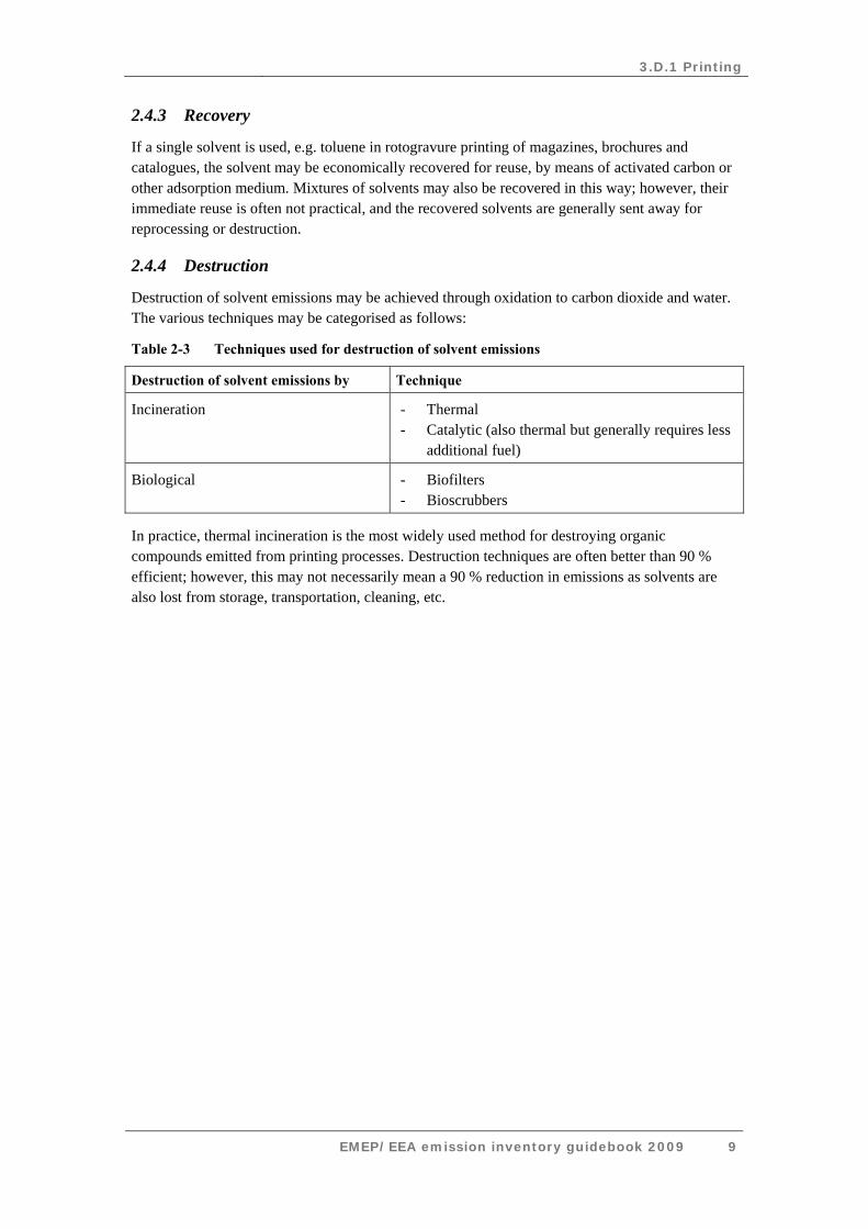
2.4.4 Destruction
Destruction of solvent emissions may be achieved through oxidation to carbon dioxide and water. The various techniques may be categorised as follows:
Table 2-3 Techniques used for destruction of solvent emissions
Destruction of solvent emissions by Technique
Incineration - Thermal - Catalytic (also thermal but generally requires less
additional fuel)
Biological - Biofilters - Bioscrubbers
In practice, thermal incineration is the most widely used method for destroying organic compounds emitted from printing processes. Destruction techniques are often better than 90 % efficient; however, this may not necessarily mean a 90 % reduction in emissions as solvents are also lost from storage, transportation, cleaning, etc.
3.D.1 Printing
EMEP/EEA emission inventory guidebook 2009 10
3 Methods
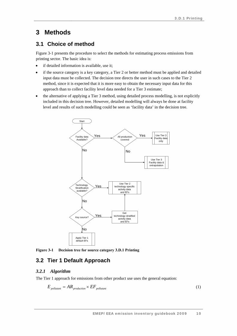
3.1 Choice of method Figure 3-1 presents the procedure to select the methods for estimating process emissions from printing sector. The basic idea is: • if detailed information is available, use it; • if the source category is a key category, a Tier 2 or better method must be applied and detailed
input data must be collected. The decision tree directs the user in such cases to the Tier 2 method, since it is expected that it is more easy to obtain the necessary input data for this approach than to collect facility level data needed for a Tier 3 estimate;
• the alternative of applying a Tier 3 method, using detailed process modelling, is not explicitly included in this decision tree. However, detailed modelling will always be done at facility level and results of such modelling could be seen as ‘facility data’ in the decision tree.
Start
Facility dataAvailable?
All productioncovered
Use Tier 3Facility data
only
Technology Stratificationavailable?
Use Tier 2technology specific
activity data and EFs
Key source?
Get technology stratified
activity data and EFs
Apply Tier 1default EFs
Yes Yes
Yes
Yes
No
No
No
No
Use Tier 3Facility data &extrapolation
Figure 3-1 Decision tree for source category 3.D.1 Printing
3.2 Tier 1 Default Approach
3.2.1 Algorithm The Tier 1 approach for emissions from other product use uses the general equation:
pollutantproductionpollutant EFARE ×= (1)

3.D.1 Printing
EMEP/EEA emission inventory guidebook 2009 11
This equation is applied at the national level. It involves either the use of solvent consumption data or combining ink consumption with emission factors for the industry. Unless the solvent consumption data is used, no account is taken of the use of water-based or low solvent inks, and no account is taken of the extent of controls such as incineration.
In cases where specific abatement options are to be taken into account a Tier 1 method is not applicable and a Tier 2 or Tier 3 approach must be used.
3.2.2 Default emission factors
The table below provides the default emission factor for NMVOC emissions from printing. It has been taken from the International Institute for Applied Systems Analysis (IIASA) Greenhouse Gas and Air Pollution Interactions and Synergies (GAINS) model, for the year 2000. A weighted average emission factor is calculated, considering all printing sources in the model.
It must be stressed that since the processes in the printing industry are very different, the Tier 1 emission factor has a very wide uncertainty range. It is recommended to use the Tier 2 approach if possible.
Table 3-1 Tier 1 emission factors for source category 3.D.1 Printing
CodeNFR Source Category 3.D.1
FuelNot applicable
Not estimated
Lower UpperNMVOC 500 g/kg ink 30 2100 IIASA (2008)
NA
Tier 1 default emission factorsName
Pollutant
Printing
NOx, CO, SOx, NH3, TSP, PM10, Pb, Cd, Hg, As, Cr, Cu, Ni, Se, Zn, Aldrin, Chlordane, Chlordecone, Dieldrin, Endrin, Heptachlor, Heptabromo-biphenyl, Mirex, Toxaphene, HCH, DDT, PCB, PCDD/F, Benzo(a)pyrene, Benzo(b)fluoranthene, Benzo(k)fluoranthene, Indeno(1,2,3-cd)pyrene, Total 4 PAHs, HCB, PCP, SCCPPM2.5
Value Unit 95% confidence interval Reference
Note that the emission factor for this source category can exceed the 100 % value (1 kg/kg), which is due to the mixing of ink with solvent before printing.
3.2.3 Activity data
Basic activity statistics for using the Tier 1 emission factor is the annual national ink consumption of the printing industry.

3.D.1 Printing
EMEP/EEA emission inventory guidebook 2009 12
3.3 Tier 2 technology-specific approach
3.3.1 Algorithm
The Tier 2 approach is similar to the Tier 1 approach. To apply the Tier 2 approach, both the activity data and the emission factors need to be stratified according to the different printing processes that may occur in the country. These processes are:
• heat set offset
• publication gravure
• flexography and rotogravure in packaging.
The following approach is used to estimate emissions from printing.
Stratify the printing in the country to model the different process types occurring in the national printing industry into the inventory by:
• defining the use of printing processes using each of the separate process types (together called ‘technologies’ in the formulae below) separately; and
• applying technology specific emission factors for each process type:
∑ ×=ieslogtechno
ttanpollu,ylogtechnoylogtechno,usettanpollu EFARE (2)
where:
ARuse,technology = the use of ink for printing using this specific technology,
EFtechnology,pollutant = the emission factor for this technology and this pollutant.
If no direct activity data are available, penetration of different technologies within the printing industry could be estimated from data on capacities, number of employees or other data that reflect the relative size of each of the different technologies.
A country where only one technology is implemented is basically a special case of the above approaches. The penetration of this technology in such a case is 100 % and the algorithm in equation (2) reduces to:
,pollutanttechnologyproductionpollutant EFARE ×= (3)
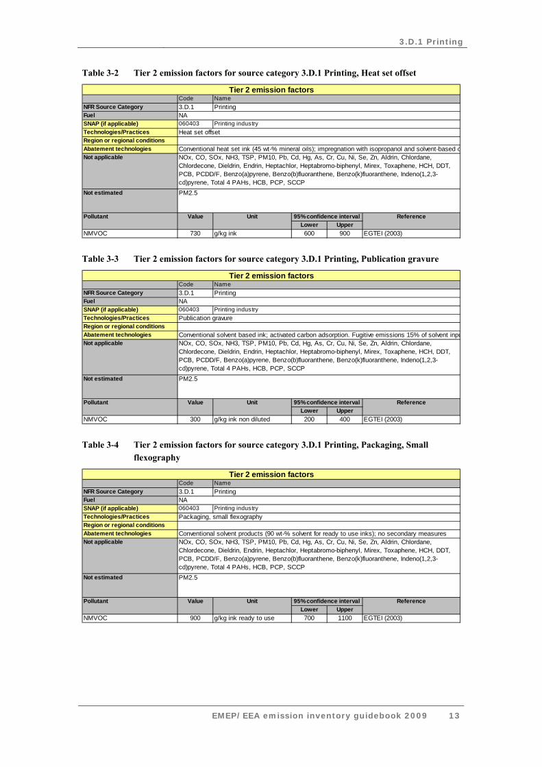
3.3.2 Technology-specific emission factors
This section presents conventional (‘uncontrolled’) emission factors for printing activities for each of the three process types considered in this document. Abatement efficiencies for controlled emissions can be found in the abatement section of this chapter.
Care should be taken when applying these emission factors, because the required activity data are different for different processes. More info can be obtained from the EGTEI background documents (EGTEI, 2003).
3.D.1 Printing
EMEP/EEA emission inventory guidebook 2009 13
Table 3-2 Tier 2 emission factors for source category 3.D.1 Printing, Heat set offset
CodeNFR Source Category 3.D.1FuelSNAP (if applicable) 060403Technologies/PracticesRegion or regional conditionsAbatement technologiesNot applicable
Not estimated
Lower UpperNMVOC 730 g/kg ink 600 900 EGTEI (2003)
Tier 2 emission factorsNamePrinting
NAPrinting industry
Heat set offset
Conventional heat set ink (45 wt-% mineral oils); impregnation with isopropanol and solvent-based cNOx, CO, SOx, NH3, TSP, PM10, Pb, Cd, Hg, As, Cr, Cu, Ni, Se, Zn, Aldrin, Chlordane, Chlordecone, Dieldrin, Endrin, Heptachlor, Heptabromo-biphenyl, Mirex, Toxaphene, HCH, DDT, PCB, PCDD/F, Benzo(a)pyrene, Benzo(b)fluoranthene, Benzo(k)fluoranthene, Indeno(1,2,3-cd)pyrene, Total 4 PAHs, HCB, PCP, SCCPPM2.5
Pollutant Value Unit 95% confidence interval Reference
Table 3-3 Tier 2 emission factors for source category 3.D.1 Printing, Publication gravure
CodeNFR Source Category 3.D.1FuelSNAP (if applicable) 060403Technologies/PracticesRegion or regional conditionsAbatement technologiesNot applicable
Not estimated
Lower UpperNMVOC 300 g/kg ink non diluted 200 400 EGTEI (2003)
Tier 2 emission factorsNamePrinting
NAPrinting industry
Publication gravure
Conventional solvent based ink; activated carbon adsorption. Fugitive emissions 15% of solvent inpuNOx, CO, SOx, NH3, TSP, PM10, Pb, Cd, Hg, As, Cr, Cu, Ni, Se, Zn, Aldrin, Chlordane, Chlordecone, Dieldrin, Endrin, Heptachlor, Heptabromo-biphenyl, Mirex, Toxaphene, HCH, DDT, PCB, PCDD/F, Benzo(a)pyrene, Benzo(b)fluoranthene, Benzo(k)fluoranthene, Indeno(1,2,3-cd)pyrene, Total 4 PAHs, HCB, PCP, SCCPPM2.5
Pollutant Value Unit 95% confidence interval Reference
Table 3-4 Tier 2 emission factors for source category 3.D.1 Printing, Packaging, Small flexography
CodeNFR Source Category 3.D.1FuelSNAP (if applicable) 060403Technologies/PracticesRegion or regional conditionsAbatement technologiesNot applicable
Not estimated
Lower UpperNMVOC 900 g/kg ink ready to use 700 1100 EGTEI (2003)
Tier 2 emission factorsNamePrinting
NAPrinting industry
Packaging, small flexography
Conventional solvent products (90 wt-% solvent for ready to use inks); no secondary measuresNOx, CO, SOx, NH3, TSP, PM10, Pb, Cd, Hg, As, Cr, Cu, Ni, Se, Zn, Aldrin, Chlordane, Chlordecone, Dieldrin, Endrin, Heptachlor, Heptabromo-biphenyl, Mirex, Toxaphene, HCH, DDT, PCB, PCDD/F, Benzo(a)pyrene, Benzo(b)fluoranthene, Benzo(k)fluoranthene, Indeno(1,2,3-cd)pyrene, Total 4 PAHs, HCB, PCP, SCCPPM2.5
Pollutant Value Unit 95% confidence interval Reference
3.D.1 Printing
EMEP/EEA emission inventory guidebook 2009 14
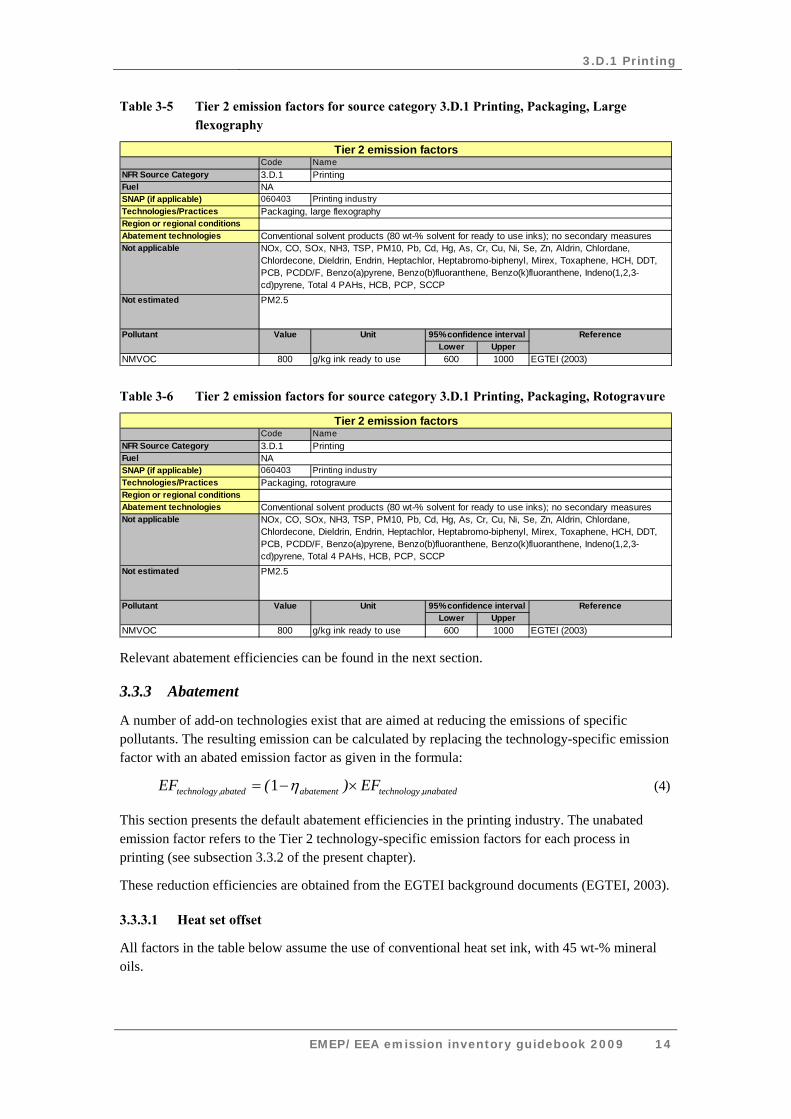
Table 3-5 Tier 2 emission factors for source category 3.D.1 Printing, Packaging, Large flexography
CodeNFR Source Category 3.D.1FuelSNAP (if applicable) 060403Technologies/PracticesRegion or regional conditionsAbatement technologiesNot applicable
Not estimated
Lower UpperNMVOC 800 g/kg ink ready to use 600 1000 EGTEI (2003)
Tier 2 emission factorsNamePrinting
NAPrinting industry
Packaging, large flexography
Conventional solvent products (80 wt-% solvent for ready to use inks); no secondary measuresNOx, CO, SOx, NH3, TSP, PM10, Pb, Cd, Hg, As, Cr, Cu, Ni, Se, Zn, Aldrin, Chlordane, Chlordecone, Dieldrin, Endrin, Heptachlor, Heptabromo-biphenyl, Mirex, Toxaphene, HCH, DDT, PCB, PCDD/F, Benzo(a)pyrene, Benzo(b)fluoranthene, Benzo(k)fluoranthene, Indeno(1,2,3-cd)pyrene, Total 4 PAHs, HCB, PCP, SCCPPM2.5
Pollutant Value Unit 95% confidence interval Reference
Table 3-6 Tier 2 emission factors for source category 3.D.1 Printing, Packaging, Rotogravure
CodeNFR Source Category 3.D.1FuelSNAP (if applicable) 060403Technologies/PracticesRegion or regional conditionsAbatement technologiesNot applicable
Not estimated
Lower UpperNMVOC 800 g/kg ink ready to use 600 1000 EGTEI (2003)
Tier 2 emission factorsNamePrinting
NAPrinting industry
Packaging, rotogravure
Conventional solvent products (80 wt-% solvent for ready to use inks); no secondary measuresNOx, CO, SOx, NH3, TSP, PM10, Pb, Cd, Hg, As, Cr, Cu, Ni, Se, Zn, Aldrin, Chlordane, Chlordecone, Dieldrin, Endrin, Heptachlor, Heptabromo-biphenyl, Mirex, Toxaphene, HCH, DDT, PCB, PCDD/F, Benzo(a)pyrene, Benzo(b)fluoranthene, Benzo(k)fluoranthene, Indeno(1,2,3-cd)pyrene, Total 4 PAHs, HCB, PCP, SCCPPM2.5
Pollutant Value Unit 95% confidence interval Reference
Relevant abatement efficiencies can be found in the next section.
3.3.3 Abatement
A number of add-on technologies exist that are aimed at reducing the emissions of specific pollutants. The resulting emission can be calculated by replacing the technology-specific emission factor with an abated emission factor as given in the formula:
unabated,technologyabatementabated,technology EF)(EF ×−= η1 (4)
This section presents the default abatement efficiencies in the printing industry. The unabated emission factor refers to the Tier 2 technology-specific emission factors for each process in printing (see subsection 3.3.2 of the present chapter).
These reduction efficiencies are obtained from the EGTEI background documents (EGTEI, 2003).
3.3.3.1 Heat set offset
All factors in the table below assume the use of conventional heat set ink, with 45 wt-% mineral oils.
3.D.1 Printing
EMEP/EEA emission inventory guidebook 2009 15
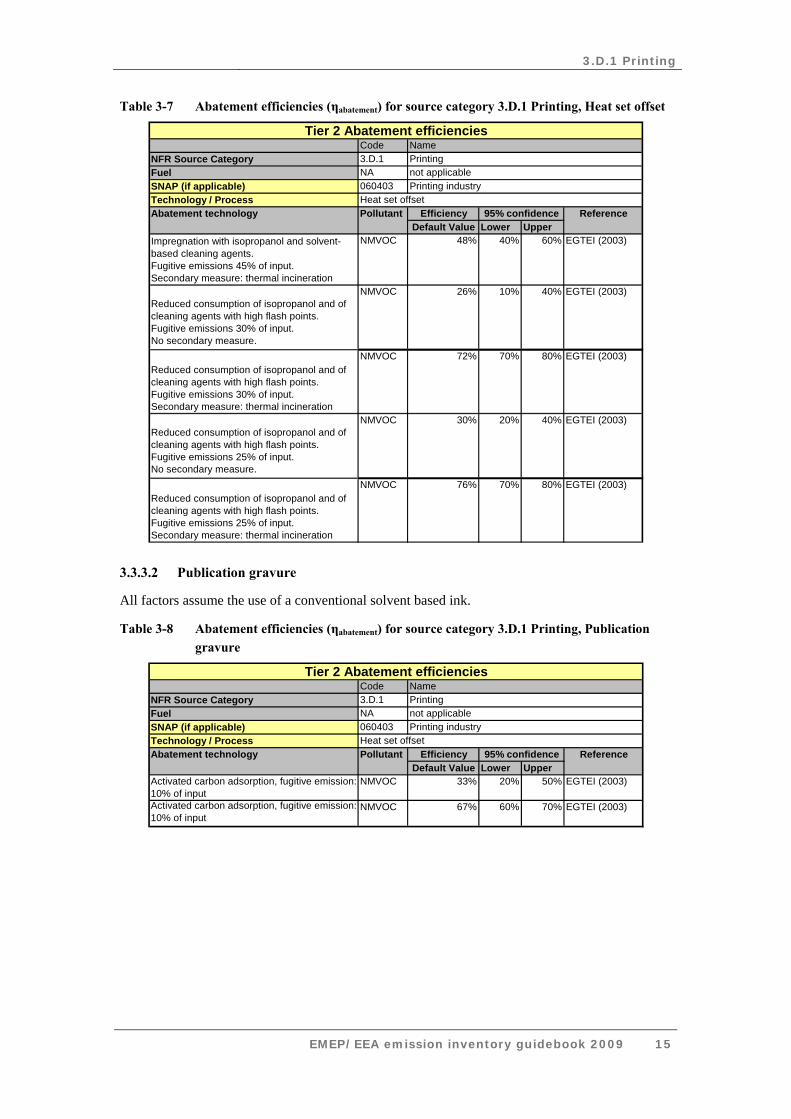
Table 3-7 Abatement efficiencies (ηabatement) for source category 3.D.1 Printing, Heat set offset
CodeNFR Source Category 3.D.1Fuel NASNAP (if applicable) 060403Technology / Process
EfficiencyDefault Value Lower Upper
Impregnation with isopropanol and solvent-based cleaning agents.Fugitive emissions 45% of input.Secondary measure: thermal incineration
NMVOC 48% 40% 60% EGTEI (2003)
Reduced consumption of isopropanol and of cleaning agents with high flash points.Fugitive emissions 30% of input.No secondary measure.
NMVOC 26% 10% 40% EGTEI (2003)
Reduced consumption of isopropanol and of cleaning agents with high flash points.Fugitive emissions 30% of input.Secondary measure: thermal incineration
NMVOC 72% 70% 80% EGTEI (2003)
Reduced consumption of isopropanol and of cleaning agents with high flash points.Fugitive emissions 25% of input.No secondary measure.
NMVOC 30% 20% 40% EGTEI (2003)
Reduced consumption of isopropanol and of cleaning agents with high flash points.Fugitive emissions 25% of input.Secondary measure: thermal incineration
NMVOC 76% 70% 80% EGTEI (2003)
Printing industryHeat set offset
Tier 2 Abatement efficienciesNamePrintingnot applicable
Abatement technology Pollutant 95% confidence Reference
3.3.3.2 Publication gravure
All factors assume the use of a conventional solvent based ink.
Table 3-8 Abatement efficiencies (ηabatement) for source category 3.D.1 Printing, Publication gravure
CodeNFR Source Category 3.D.1Fuel NASNAP (if applicable) 060403Technology / Process
EfficiencyDefault Value Lower Upper
Activated carbon adsorption, fugitive emission: 10% of input
NMVOC 33% 20% 50% EGTEI (2003)
Activated carbon adsorption, fugitive emission: 10% of input
NMVOC 67% 60% 70% EGTEI (2003)
Abatement technology Pollutant 95% confidence Reference
Printing industryHeat set offset
Tier 2 Abatement efficienciesNamePrintingnot applicable
3.D.1 Printing
EMEP/EEA emission inventory guidebook 2009 16
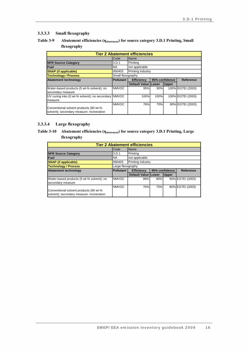
3.3.3.3 Small flexography Table 3-9 Abatement efficiencies (ηabatement) for source category 3.D.1 Printing, Small
flexography
CodeNFR Source Category 3.D.1Fuel NASNAP (if applicable) 060403Technology / Process
EfficiencyDefault Value Lower Upper
Water-based products (5 wt-% solvent); no secondary measure
NMVOC 95% 90% 100% EGTEI (2003)
UV curing inks (0 wt-% solvent); no secondary measure
NMVOC 100% 100% 100% EGTEI (2003)
Conventional solvent products (90 wt-% solvent); secondary measure: incineration
NMVOC 76% 70% 80% EGTEI (2003)
Abatement technology Pollutant 95% confidence Reference
Printing industrySmall flexography
Tier 2 Abatement efficienciesNamePrintingnot applicable
3.3.3.4 Large flexography Table 3-10 Abatement efficiencies (ηabatement) for source category 3.D.1 Printing, Large
flexography
CodeNFR Source Category 3.D.1Fuel NASNAP (if applicable) 060403Technology / Process
EfficiencyDefault Value Lower Upper
Water-based products (5 wt-% solvent); no secondary measure
NMVOC 88% 80% 90% EGTEI (2003)
Conventional solvent products (90 wt-% solvent); secondary measure: incineration
NMVOC 76% 70% 80% EGTEI (2003)
Printing industryLarge flexography
Tier 2 Abatement efficienciesNamePrintingnot applicable
Abatement technology Pollutant 95% confidence Reference
3.D.1 Printing
EMEP/EEA emission inventory guidebook 2009 17
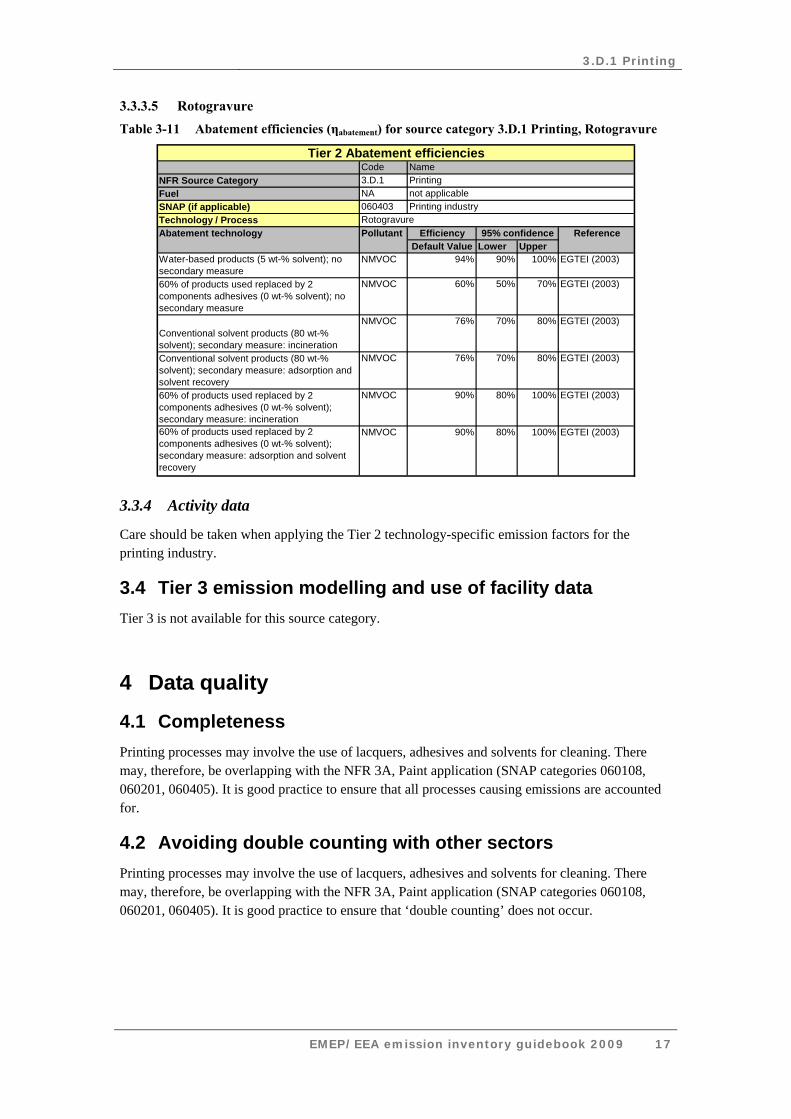
3.3.3.5 Rotogravure Table 3-11 Abatement efficiencies (ηabatement) for source category 3.D.1 Printing, Rotogravure
CodeNFR Source Category 3.D.1Fuel NASNAP (if applicable) 060403Technology / Process
EfficiencyDefault Value Lower Upper
Water-based products (5 wt-% solvent); no secondary measure
NMVOC 94% 90% 100% EGTEI (2003)
60% of products used replaced by 2 components adhesives (0 wt-% solvent); no secondary measure
NMVOC 60% 50% 70% EGTEI (2003)
Conventional solvent products (80 wt-% solvent); secondary measure: incineration
NMVOC 76% 70% 80% EGTEI (2003)
Conventional solvent products (80 wt-% solvent); secondary measure: adsorption and solvent recovery
NMVOC 76% 70% 80% EGTEI (2003)
60% of products used replaced by 2 components adhesives (0 wt-% solvent); secondary measure: incineration
NMVOC 90% 80% 100% EGTEI (2003)
60% of products used replaced by 2 components adhesives (0 wt-% solvent); secondary measure: adsorption and solvent recovery
NMVOC 90% 80% 100% EGTEI (2003)
Abatement technology Pollutant 95% confidence Reference
Printing industryRotogravure
Tier 2 Abatement efficienciesNamePrintingnot applicable
3.3.4 Activity data
Care should be taken when applying the Tier 2 technology-specific emission factors for the printing industry.
3.4 Tier 3 emission modelling and use of facility data Tier 3 is not available for this source category.
4 Data quality
4.1 Completeness Printing processes may involve the use of lacquers, adhesives and solvents for cleaning. There may, therefore, be overlapping with the NFR 3A, Paint application (SNAP categories 060108, 060201, 060405). It is good practice to ensure that all processes causing emissions are accounted for.
4.2 Avoiding double counting with other sectors Printing processes may involve the use of lacquers, adhesives and solvents for cleaning. There may, therefore, be overlapping with the NFR 3A, Paint application (SNAP categories 060108, 060201, 060405). It is good practice to ensure that ‘double counting’ does not occur.
3.D.1 Printing
EMEP/EEA emission inventory guidebook 2009 18
4.3 Verification Verification of emission estimates will be primarily through inter-comparison between countries, since some countries can be expected to carry out the detailed methodology. Significant difference in emissions of organic compounds per tonne of ink used, or per capita, may indicate poor quality data.
In addition, measurements carried out at individual print works could be used to establish the actual efficiency of abatement equipment.
4.3.1 Best Available Technique emission factors
4.3.1.1 Printing with heatset web offset
BAT is to use a combination of techniques for printing, cleaning, waste gas management, as well as generic BAT to reduce the sum of fugitive emissions and the VOCs remaining after waste gas treatment. Associated emission values for the combined isopropyl alcohol (IPA) and cleaning solvent are:
• for new or upgraded presses, 2.5 to 10 % VOC expressed as wt- % of the ink consumption;
• for existing presses, 5 to 15 % VOC expressed as wt- % of the ink consumption.
Note that the top half of the ranges are associated with IPA emissions for ‘difficult’ jobs (as defined). Concentration techniques cannot be used because of odour problems.
4.3.1.2 Printing flexible packaging by flexography and packaging gravure
BAT is to use a combination of techniques described to reduce the sum of fugitive and non-fugitive VOC emissions. Associated emission values for the three scenarios occurring in the industry are (using the reference emission defined in Annex IIb to the SED):
• (scenario 1): installations where all production machines are solvent-based and connected to abatement equipment:
o with incineration: total emissions 7.5–12.5 % of the reference emission, o with solvent recovery: total emissions 10.0–15.0 % of the reference emission;
• (scenario 2): existing installations, where there is waste gas abatement equipment, but not all solvent-based production machines are connected:
(2.1) for the machines that are connected to the abatement equipment: o with incineration: total emissions 7.5–12.5 % of reference emission relating to those
machines, o with solvent recovery: total emissions 10.0–15.0 % of the reference emission relating to
those machines, (2.2) for the machines not connected to waste gas treatment, BAT is one of:
o use low solvent or solvent-free products on these machines, o connect to the waste gas abatement equipment when there is capacity, o preferentially run high solvent content work on machines connected to waste gas
abatement; • (scenario 3): where installations have no waste gas abatement equipment and are using
substitution, it is BAT to follow the developments of low solvent and solvent-free inks, varnishes and adhesives, and continuously decrease the amount of solvents consumed.
3.D.1 Printing
EMEP/EEA emission inventory guidebook 2009 19
In scenarios 1 and 2.1, where an installation has a solid solvent ratio of higher than 1:5.5 for the total of the solvent-based inks, varnishes and adhesives, the emission values may not be obtainable. In this case, it is BAT to cover the ink fountains or apply chamber doctor blades and to apply a suitable combination of other techniques, as described.
BAT is also to:
• minimise energy consumption when optimising waste gas treatment in all sites;
• seek opportunities to recover and use any surplus energy in all sites.
4.3.1.3 Printing with publication gravure
BAT is to:
• reduce the sum of fugitive emissions and the VOCs remaining after gas treatment, expressed as total solvent input:
o for new plants to 4 to 5 %, using techniques applicable to new plants, o for existing plants to 5 to 7 %, using techniques applicable to existing plants;
• prevent the excessive use of energy by using the optimum number of regenerations required to maintain emissions within the emission values expressed;
• reduce the emissions of toluene to a municipal sewer to below 10 mg/l by air stripping.
4.4 Developing a consistent time series and recalculation No specific issues.
4.5 Uncertainty assessment No specific issues.
4.5.1 Emission factor uncertainties
This requires audits of the major plants, perhaps 40 for a country like France. Such audits are time consuming, and may not be possible if solvent management plans are not a requirement of process authorisation.
Priority areas for improvement are a detailed review of the rotogravure and flexographic techniques to improve the current emission factors and a methodology for assessing the extent of abatement and its effectiveness.
Note that, in the EU, the countries with the largest rotogravure and flexographic industries are thought to be Italy, Germany, UK and France (Allemand 1990).
4.5.2 Activity data uncertainties
No specific issues.
4.6 Inventory quality assurance/quality control QA/QC No specific issues.
3.D.1 Printing
EMEP/EEA emission inventory guidebook 2009 20
4.7 Gridding In the simpler methodology, no point sources are defined. It is therefore good practice to do spatial disaggregation on a population basis, or if possible, using the distribution of engineering workers.
In the detailed methodology, large printing processes are identified. The residual may be disaggregated according to population, or if possible, distribution of engineering workers.
4.8 Reporting and documentation No specific issues
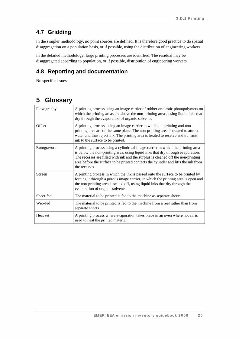
5 Glossary Flexography A printing process using an image carrier of rubber or elastic photopolymers on
which the printing areas are above the non-printing areas, using liquid inks that dry through the evaporation of organic solvents.
Offset A printing process, using an image carrier in which the printing and non-printing area are of the same plane. The non-printing area is treated to attract water and thus reject ink. The printing area is treated to receive and transmit ink to the surface to be printed.
Rotogravure A printing process using a cylindrical image carrier in which the printing area is below the non-printing area, using liquid inks that dry through evaporation. The recesses are filled with ink and the surplus is cleaned off the non-printing area before the surface to be printed contacts the cylinder and lifts the ink from the recesses.
Screen A printing process in which the ink is passed onto the surface to be printed by forcing it through a porous image carrier, in which the printing area is open and the non-printing area is sealed off, using liquid inks that dry through the evaporation of organic solvents.
Sheet-fed The material to be printed is fed to the machine as separate sheets.
Web-fed The material to be printed is fed to the machine from a reel rather than from separate sheets.
Heat set A printing process where evaporation takes place in an oven where hot air is used to heat the printed material.
3.D.1 Printing
EMEP/EEA emission inventory guidebook 2009 21
6 References Allemand N. (1990). Control of Emissions of Volatile Organic Compounds from Printing Industries, EEC Contract B 6611-37-89, CITEPA (The Interprofessional Technical Centre for Studies on Atmospheric Pollution).
Aminal, Vito and Sitmae Consultancy BV (2002). ‘Evaluatie van het reductiepotentieel voor VOS emissies naar het compartiment lucht en de problematiek van de implementatie van de Europese richtlijn 99/13/EG in de grafische sector in Vlaanderen; deel 3’, Ministerie van de Vlaamse Gemeenschap, Afdeling Algemeen Milieu- en Natuurbeleid.
BMLFUW Austria (2003). Stand der Technik bei ausgewählten Anlagen zur Oberflächenbehandelung mit organischen Lösungsmitteln, Bundesministerium für Land- und Forstwirtschaft, Umwelt und Wasserwirtschaft.
EC (1999). ‘Council Directive 1999/13/EC on the limitation of emissions of volatile organic compounds due to the use of organic solvents in certain activities and installations’, OJ L 85, 29.3.1999, p. 1, amended by Corrigendum, OJ L 188, 21.7.1999, p. 54 (1999/13) and Corrigendum, OJ L 240, 10.9.1999, p. 24 (1999/13).
EGTEI (2003). Final background documents on the sectors ‘Heat Set Offset’, ‘Publication Gravure’ and ‘Flexography and Rotogravure in Packaging’. Prepared in the framework of EGTEI by CITEPA, Paris.
EGTEI (2005). Heatset Offset: synopsis sheet.
European Commission (2007). Integrated Pollution Prevention and Control (IPPC). Reference document on Best Available Techniques on Surface Treatment using Organic Solvents, August 2007.
IIASA (2008). Greenhouse Gas and Air Pollution Interactions and Synergies (GAINS) model, www.iiasa.ac.at/rains/gains-online.html.
IMPEL (2000). ‘Good practice fact sheet — PRINTERS’, European Union Network for the Implementation and Enforcement of Environmental Law, Antal Sidor 42.
Integraf (2005). Proposal for BAT ranges for Heatset.
Integraf and EGF (1999). Printing and the Environment, Guidance on BAT in Printing Industries.
TWG (2004). Compiled comments of the TWG on STS draft 1, May 2004.
UBA Germany (2003). ‘Integrated Pollution Prevention and Control in selected Industrial Activities; Installations for Surface Treatment using organic solvents for Dressing, Impregnating,
3.D.1 Printing
EMEP/EEA emission inventory guidebook 2009 22
Printing, Coating. Part II: Printing.’ Federal Environmental Agency, Berlin, 200 94 324.
Verspoor (2002). Integraf representative. Personal communication, October 2002.
Vito (1998). ‘Beste Beschikbare Technieken voor de Grafische Sector’, BBT kenniscentrum Vlaamse Instelling voor Technologisch Onderzoek (VITO).
VROM (2004). ‘Diffuse Oplosmiddelemissies in Verpakkingdiepdruk en Flexo: Deel 2. Meten en Verminderen’. Netherlands Ministry of Housing, Spatial Planning and the Environment in the Netherlands
7 Point of enquiry Enquiries concerning this chapter should be directed to the relevant leader(s) of the Task Force on Emission Inventories and Projection’s expert panel on combustion and industry. Please refer to the TFEIP website (www.tfeip-secretariat.org/) for the contact details of the current expert panel leaders.