Embed Size (px)
Citation preview

3DLDF User and Reference Manual3-dimensional drawing with MetaPost output.
Manual edition 1.1.5.1 for 3DLDF Version 1.1.5.1January 2004
Laurence D. Finston

This is the 3DLDF User and Reference Manual, edition 1.1.5.1 for 3DLDF 1.1.5.1. Thismanual was last updated on 16 January 2004. 3DLDF is a GNU package for three-dimensional drawing with MetaPost output. The author is Laurence D. Finston.
Copyright c© 2003, 2004 Laurence D. Finston.
Permission is granted to copy, distribute and/or modify this document under theterms of the GNU Free Documentation License, Version 1.2 or any later versionpublished by the Free Software Foundation; with no Invariant Sections, noFront-Cover Texts, and no Back-Cover Texts. A copy of the license is includedin the section entitled “GNU Free Documentation License”.
i
Short Contents
1 Introduction. . . . . . . . . . . . . . . . . . . . . . . . . . . . . . . . . . . 1
2 Points . . . . . . . . . . . . . . . . . . . . . . . . . . . . . . . . . . . . . . 10
3 Transforming Points . . . . . . . . . . . . . . . . . . . . . . . . . . . . 13
4 Transforms . . . . . . . . . . . . . . . . . . . . . . . . . . . . . . . . . . . 19
5 Drawing and Labeling Points . . . . . . . . . . . . . . . . . . . . . . 24
6 Paths . . . . . . . . . . . . . . . . . . . . . . . . . . . . . . . . . . . . . . 28
7 Plane Figures . . . . . . . . . . . . . . . . . . . . . . . . . . . . . . . . . 36
8 Solid Figures . . . . . . . . . . . . . . . . . . . . . . . . . . . . . . . . . 47
9 Pictures . . . . . . . . . . . . . . . . . . . . . . . . . . . . . . . . . . . . . 54
10 Intersections . . . . . . . . . . . . . . . . . . . . . . . . . . . . . . . . . . 73
11 Installing and Running 3DLDF . . . . . . . . . . . . . . . . . . . . . 74
12 Typedefs and Utility Structures . . . . . . . . . . . . . . . . . . . . . 81
13 Global Constants and Variables . . . . . . . . . . . . . . . . . . . . . 82
14 Dynamic Allocation of Shapes . . . . . . . . . . . . . . . . . . . . . . 84
15 System Information . . . . . . . . . . . . . . . . . . . . . . . . . . . . . 85
16 Color Reference. . . . . . . . . . . . . . . . . . . . . . . . . . . . . . . . 88
17 Input and Output . . . . . . . . . . . . . . . . . . . . . . . . . . . . . . 92
18 Shape Reference . . . . . . . . . . . . . . . . . . . . . . . . . . . . . . . 93
19 Transform Reference . . . . . . . . . . . . . . . . . . . . . . . . . . . . 96
20 Label Reference . . . . . . . . . . . . . . . . . . . . . . . . . . . . . . . 108
21 Picture Reference . . . . . . . . . . . . . . . . . . . . . . . . . . . . . 111
22 Point Reference . . . . . . . . . . . . . . . . . . . . . . . . . . . . . . . 119
23 Focus Reference. . . . . . . . . . . . . . . . . . . . . . . . . . . . . . . 151
24 Line Reference . . . . . . . . . . . . . . . . . . . . . . . . . . . . . . . 154
25 Plane Reference . . . . . . . . . . . . . . . . . . . . . . . . . . . . . . . 157
26 Path Reference . . . . . . . . . . . . . . . . . . . . . . . . . . . . . . . 165
27 Polygon Reference . . . . . . . . . . . . . . . . . . . . . . . . . . . . . 199
28 Regular Polygon Reference . . . . . . . . . . . . . . . . . . . . . . . 205
29 Rectangle Reference . . . . . . . . . . . . . . . . . . . . . . . . . . . . 211
30 Regular Closed Plane Curve Reference . . . . . . . . . . . . . . . 216
31 Ellipse Reference . . . . . . . . . . . . . . . . . . . . . . . . . . . . . . 222
32 Circle Reference . . . . . . . . . . . . . . . . . . . . . . . . . . . . . . 238
33 Pattern Reference . . . . . . . . . . . . . . . . . . . . . . . . . . . . . 242
34 Solid Reference . . . . . . . . . . . . . . . . . . . . . . . . . . . . . . . 248
35 Faced Solid Reference . . . . . . . . . . . . . . . . . . . . . . . . . . . 257

ii
36 Cuboid Reference . . . . . . . . . . . . . . . . . . . . . . . . . . . . . 258
37 Polyhedron Reference . . . . . . . . . . . . . . . . . . . . . . . . . . . 260
38 Utility Functions . . . . . . . . . . . . . . . . . . . . . . . . . . . . . . 271
39 Adding a File . . . . . . . . . . . . . . . . . . . . . . . . . . . . . . . . 273
40 Future Plans . . . . . . . . . . . . . . . . . . . . . . . . . . . . . . . . . 275
41 Changes . . . . . . . . . . . . . . . . . . . . . . . . . . . . . . . . . . . . 278
Bibliography . . . . . . . . . . . . . . . . . . . . . . . . . . . . . . . . . . . . 280
A GNU Free Documentation License . . . . . . . . . . . . . . . . . . 282
Data Type and Variable Index . . . . . . . . . . . . . . . . . . . . . . . . 289
Function Index . . . . . . . . . . . . . . . . . . . . . . . . . . . . . . . . . . 292
Concept Index . . . . . . . . . . . . . . . . . . . . . . . . . . . . . . . . . . . 295
iii
Table of Contents
1 Introduction . . . . . . . . . . . . . . . . . . . . . . . . . . . . . . . 11.1 Sources of Information . . . . . . . . . . . . . . . . . . . . . . . . . . . . . . . . . . . 11.2 About This Manual . . . . . . . . . . . . . . . . . . . . . . . . . . . . . . . . . . . . . 2
1.2.1 Conventions . . . . . . . . . . . . . . . . . . . . . . . . . . . . . . . . . . . . 31.2.2 Illustrations . . . . . . . . . . . . . . . . . . . . . . . . . . . . . . . . . . . . 4
1.3 CWEB Documentation . . . . . . . . . . . . . . . . . . . . . . . . . . . . . . . . . . 51.4 Metafont and MetaPost . . . . . . . . . . . . . . . . . . . . . . . . . . . . . . . . . . 61.5 Caveats . . . . . . . . . . . . . . . . . . . . . . . . . . . . . . . . . . . . . . . . . . . . . . . . 7
1.5.1 Accuracy . . . . . . . . . . . . . . . . . . . . . . . . . . . . . . . . . . . . . . . 71.5.2 No Input Routine . . . . . . . . . . . . . . . . . . . . . . . . . . . . . . . 8
1.6 Ports . . . . . . . . . . . . . . . . . . . . . . . . . . . . . . . . . . . . . . . . . . . . . . . . . . . 81.7 Contributing to 3DLDF. . . . . . . . . . . . . . . . . . . . . . . . . . . . . . . . . . 9
2 Points. . . . . . . . . . . . . . . . . . . . . . . . . . . . . . . . . . . . 102.1 Declaring and Initializing Points . . . . . . . . . . . . . . . . . . . . . . . . . 102.2 Setting and Assigning to Points . . . . . . . . . . . . . . . . . . . . . . . . . 11
3 Transforming Points . . . . . . . . . . . . . . . . . . . . . . 133.1 Shifting . . . . . . . . . . . . . . . . . . . . . . . . . . . . . . . . . . . . . . . . . . . . . . . 133.2 Scaling . . . . . . . . . . . . . . . . . . . . . . . . . . . . . . . . . . . . . . . . . . . . . . . . 143.3 Shearing . . . . . . . . . . . . . . . . . . . . . . . . . . . . . . . . . . . . . . . . . . . . . . . 143.4 Rotating. . . . . . . . . . . . . . . . . . . . . . . . . . . . . . . . . . . . . . . . . . . . . . . 17
4 Transforms . . . . . . . . . . . . . . . . . . . . . . . . . . . . . . . 194.1 Applying Transforms to Points . . . . . . . . . . . . . . . . . . . . . . . . . . 204.2 Inverting Transforms . . . . . . . . . . . . . . . . . . . . . . . . . . . . . . . . . . . 21
5 Drawing and Labeling Points . . . . . . . . . . . . . . 245.1 Drawing Points . . . . . . . . . . . . . . . . . . . . . . . . . . . . . . . . . . . . . . . . 245.2 Labeling Points . . . . . . . . . . . . . . . . . . . . . . . . . . . . . . . . . . . . . . . . 26
6 Paths . . . . . . . . . . . . . . . . . . . . . . . . . . . . . . . . . . . . 286.1 Declaring and Initializing Paths . . . . . . . . . . . . . . . . . . . . . . . . . 286.2 Drawing and Filling Paths . . . . . . . . . . . . . . . . . . . . . . . . . . . . . . 30
7 Plane Figures . . . . . . . . . . . . . . . . . . . . . . . . . . . . 367.1 Regular Polygons . . . . . . . . . . . . . . . . . . . . . . . . . . . . . . . . . . . . . . 367.2 Rectangles . . . . . . . . . . . . . . . . . . . . . . . . . . . . . . . . . . . . . . . . . . . . . 397.3 Ellipses . . . . . . . . . . . . . . . . . . . . . . . . . . . . . . . . . . . . . . . . . . . . . . . . 437.4 Circles . . . . . . . . . . . . . . . . . . . . . . . . . . . . . . . . . . . . . . . . . . . . . . . . 45

iv
8 Solid Figures . . . . . . . . . . . . . . . . . . . . . . . . . . . . . 478.1 Cuboids . . . . . . . . . . . . . . . . . . . . . . . . . . . . . . . . . . . . . . . . . . . . . . . 478.2 Polyhedron . . . . . . . . . . . . . . . . . . . . . . . . . . . . . . . . . . . . . . . . . . . . 48
8.2.1 Tetrahedron . . . . . . . . . . . . . . . . . . . . . . . . . . . . . . . . . . . 488.2.2 Dodecahedron . . . . . . . . . . . . . . . . . . . . . . . . . . . . . . . . . 498.2.3 Icosahedron . . . . . . . . . . . . . . . . . . . . . . . . . . . . . . . . . . . 51
9 Pictures . . . . . . . . . . . . . . . . . . . . . . . . . . . . . . . . . . 549.1 Projections . . . . . . . . . . . . . . . . . . . . . . . . . . . . . . . . . . . . . . . . . . . . 58
9.1.1 Parallel Projections . . . . . . . . . . . . . . . . . . . . . . . . . . . . 589.1.2 The Perspective Projection . . . . . . . . . . . . . . . . . . . . . 60
9.2 Focuses . . . . . . . . . . . . . . . . . . . . . . . . . . . . . . . . . . . . . . . . . . . . . . . . 639.3 Surface Hiding . . . . . . . . . . . . . . . . . . . . . . . . . . . . . . . . . . . . . . . . . 66
10 Intersections . . . . . . . . . . . . . . . . . . . . . . . . . . . . 73
11 Installing and Running 3DLDF . . . . . . . . . . . 7411.1 Installing 3DLDF . . . . . . . . . . . . . . . . . . . . . . . . . . . . . . . . . . . . . 74
11.1.1 Template Functions . . . . . . . . . . . . . . . . . . . . . . . . . . . 7411.2 Running 3DLDF . . . . . . . . . . . . . . . . . . . . . . . . . . . . . . . . . . . . . . 75
11.2.1 Converting EPS Files . . . . . . . . . . . . . . . . . . . . . . . . . 7711.2.1.1 Emacs-Lisp Functions . . . . . . . . . . . . . . . . 78
11.2.2 Command Line Arguments . . . . . . . . . . . . . . . . . . . . 79
12 Typedefs and Utility Structures . . . . . . . . . . 81
13 Global Constants and Variables. . . . . . . . . . . 82
14 Dynamic Allocation of Shapes . . . . . . . . . . . . 84
15 System Information . . . . . . . . . . . . . . . . . . . . . . 8515.1 Endianness . . . . . . . . . . . . . . . . . . . . . . . . . . . . . . . . . . . . . . . . . . . 8515.2 Register Width . . . . . . . . . . . . . . . . . . . . . . . . . . . . . . . . . . . . . . . 8615.3 Get Second Largest Real . . . . . . . . . . . . . . . . . . . . . . . . . . . . . . . 86
16 Color Reference . . . . . . . . . . . . . . . . . . . . . . . . . 8816.1 Data Members . . . . . . . . . . . . . . . . . . . . . . . . . . . . . . . . . . . . . . . . 8816.2 Constructors and Setting Functions . . . . . . . . . . . . . . . . . . . . . 8816.3 Operators . . . . . . . . . . . . . . . . . . . . . . . . . . . . . . . . . . . . . . . . . . . . 8916.4 Modifying . . . . . . . . . . . . . . . . . . . . . . . . . . . . . . . . . . . . . . . . . . . . 8916.5 Showing . . . . . . . . . . . . . . . . . . . . . . . . . . . . . . . . . . . . . . . . . . . . . . 9016.6 Querying . . . . . . . . . . . . . . . . . . . . . . . . . . . . . . . . . . . . . . . . . . . . . 9016.7 Defining and Initializing Colors . . . . . . . . . . . . . . . . . . . . . . . . . 9016.8 Namespace Colors. . . . . . . . . . . . . . . . . . . . . . . . . . . . . . . . . . . . . 90

v
17 Input and Output . . . . . . . . . . . . . . . . . . . . . . . 9217.1 Global Variables . . . . . . . . . . . . . . . . . . . . . . . . . . . . . . . . . . . . . . 9217.2 I/O Functions . . . . . . . . . . . . . . . . . . . . . . . . . . . . . . . . . . . . . . . . 92
18 Shape Reference . . . . . . . . . . . . . . . . . . . . . . . . . 9318.1 Data Members . . . . . . . . . . . . . . . . . . . . . . . . . . . . . . . . . . . . . . . . 9318.2 Operators . . . . . . . . . . . . . . . . . . . . . . . . . . . . . . . . . . . . . . . . . . . . 9318.3 Copying . . . . . . . . . . . . . . . . . . . . . . . . . . . . . . . . . . . . . . . . . . . . . . 9318.4 Modifying . . . . . . . . . . . . . . . . . . . . . . . . . . . . . . . . . . . . . . . . . . . . 9318.5 Affine Transformations . . . . . . . . . . . . . . . . . . . . . . . . . . . . . . . . 9418.6 Applying Transformations . . . . . . . . . . . . . . . . . . . . . . . . . . . . . 9418.7 Clearing . . . . . . . . . . . . . . . . . . . . . . . . . . . . . . . . . . . . . . . . . . . . . . 9418.8 Querying . . . . . . . . . . . . . . . . . . . . . . . . . . . . . . . . . . . . . . . . . . . . . 9418.9 Showing . . . . . . . . . . . . . . . . . . . . . . . . . . . . . . . . . . . . . . . . . . . . . . 9418.10 Outputting . . . . . . . . . . . . . . . . . . . . . . . . . . . . . . . . . . . . . . . . . . 94
19 Transform Reference . . . . . . . . . . . . . . . . . . . . . 9619.1 Data Members . . . . . . . . . . . . . . . . . . . . . . . . . . . . . . . . . . . . . . . . 9619.2 Global Variables and Constants . . . . . . . . . . . . . . . . . . . . . . . . 9619.3 Constructors . . . . . . . . . . . . . . . . . . . . . . . . . . . . . . . . . . . . . . . . . . 9619.4 Operators . . . . . . . . . . . . . . . . . . . . . . . . . . . . . . . . . . . . . . . . . . . . 9619.5 Matrix Inversion . . . . . . . . . . . . . . . . . . . . . . . . . . . . . . . . . . . . . . 9919.6 Setting Values . . . . . . . . . . . . . . . . . . . . . . . . . . . . . . . . . . . . . . . . 9919.7 Querying . . . . . . . . . . . . . . . . . . . . . . . . . . . . . . . . . . . . . . . . . . . . . 9919.8 Returning Information . . . . . . . . . . . . . . . . . . . . . . . . . . . . . . . . 10019.9 Showing . . . . . . . . . . . . . . . . . . . . . . . . . . . . . . . . . . . . . . . . . . . . . 10019.10 Affine Transformations . . . . . . . . . . . . . . . . . . . . . . . . . . . . . . 10119.11 Alignment with an Axis . . . . . . . . . . . . . . . . . . . . . . . . . . . . . 10519.12 Resetting . . . . . . . . . . . . . . . . . . . . . . . . . . . . . . . . . . . . . . . . . . . 10719.13 Cleaning . . . . . . . . . . . . . . . . . . . . . . . . . . . . . . . . . . . . . . . . . . . 107
20 Label Reference . . . . . . . . . . . . . . . . . . . . . . . . 10820.1 Data Members . . . . . . . . . . . . . . . . . . . . . . . . . . . . . . . . . . . . . . . 10820.2 Copying . . . . . . . . . . . . . . . . . . . . . . . . . . . . . . . . . . . . . . . . . . . . . 10920.3 Outputting . . . . . . . . . . . . . . . . . . . . . . . . . . . . . . . . . . . . . . . . . . 109
vi
21 Picture Reference . . . . . . . . . . . . . . . . . . . . . . 11121.1 Data Members . . . . . . . . . . . . . . . . . . . . . . . . . . . . . . . . . . . . . . . 11121.2 Global Variables . . . . . . . . . . . . . . . . . . . . . . . . . . . . . . . . . . . . . 11121.3 Constructors . . . . . . . . . . . . . . . . . . . . . . . . . . . . . . . . . . . . . . . . . 11121.4 Operators . . . . . . . . . . . . . . . . . . . . . . . . . . . . . . . . . . . . . . . . . . . 11221.5 Affine Transformations . . . . . . . . . . . . . . . . . . . . . . . . . . . . . . . 11321.6 Modifying . . . . . . . . . . . . . . . . . . . . . . . . . . . . . . . . . . . . . . . . . . . 11321.7 Showing . . . . . . . . . . . . . . . . . . . . . . . . . . . . . . . . . . . . . . . . . . . . . 11421.8 Outputting . . . . . . . . . . . . . . . . . . . . . . . . . . . . . . . . . . . . . . . . . . 114
21.8.1 Namespaces . . . . . . . . . . . . . . . . . . . . . . . . . . . . . . . . . 11421.8.1.1 Namespace Projections . . . . . . . . . . . . . . 11421.8.1.2 Namespace Sorting . . . . . . . . . . . . . . . . . . 114
21.8.2 Output Functions . . . . . . . . . . . . . . . . . . . . . . . . . . . 115
22 Point Reference . . . . . . . . . . . . . . . . . . . . . . . . 11922.1 Data Members . . . . . . . . . . . . . . . . . . . . . . . . . . . . . . . . . . . . . . . 11922.2 Typedefs and Utility Structures . . . . . . . . . . . . . . . . . . . . . . . 12122.3 Global Constants and Variables . . . . . . . . . . . . . . . . . . . . . . . 12222.4 Constructors and Setting Functions . . . . . . . . . . . . . . . . . . . . 12222.5 Destructor . . . . . . . . . . . . . . . . . . . . . . . . . . . . . . . . . . . . . . . . . . . 12322.6 Operators . . . . . . . . . . . . . . . . . . . . . . . . . . . . . . . . . . . . . . . . . . . 12422.7 Copying . . . . . . . . . . . . . . . . . . . . . . . . . . . . . . . . . . . . . . . . . . . . . 12622.8 Querying . . . . . . . . . . . . . . . . . . . . . . . . . . . . . . . . . . . . . . . . . . . . 12622.9 Returning Coordinates . . . . . . . . . . . . . . . . . . . . . . . . . . . . . . . 12722.10 Returning Information . . . . . . . . . . . . . . . . . . . . . . . . . . . . . . . 12922.11 Modifying . . . . . . . . . . . . . . . . . . . . . . . . . . . . . . . . . . . . . . . . . . 12922.12 Affine Transformations . . . . . . . . . . . . . . . . . . . . . . . . . . . . . . 13022.13 Applying Transformations . . . . . . . . . . . . . . . . . . . . . . . . . . . 13522.14 Projecting . . . . . . . . . . . . . . . . . . . . . . . . . . . . . . . . . . . . . . . . . . 13522.15 Vector Operations . . . . . . . . . . . . . . . . . . . . . . . . . . . . . . . . . . . 13522.16 Points and Lines . . . . . . . . . . . . . . . . . . . . . . . . . . . . . . . . . . . . 14022.17 Intersections . . . . . . . . . . . . . . . . . . . . . . . . . . . . . . . . . . . . . . . . 14322.18 Drawing . . . . . . . . . . . . . . . . . . . . . . . . . . . . . . . . . . . . . . . . . . . . 14422.19 Labelling . . . . . . . . . . . . . . . . . . . . . . . . . . . . . . . . . . . . . . . . . . . 14722.20 Showing . . . . . . . . . . . . . . . . . . . . . . . . . . . . . . . . . . . . . . . . . . . . 14922.21 Outputting . . . . . . . . . . . . . . . . . . . . . . . . . . . . . . . . . . . . . . . . . 149
23 Focus Reference . . . . . . . . . . . . . . . . . . . . . . . . 15123.1 Data Members . . . . . . . . . . . . . . . . . . . . . . . . . . . . . . . . . . . . . . . 15123.2 Global Variables . . . . . . . . . . . . . . . . . . . . . . . . . . . . . . . . . . . . . 15123.3 Constructors and Setting Functions . . . . . . . . . . . . . . . . . . . . 15223.4 Operators . . . . . . . . . . . . . . . . . . . . . . . . . . . . . . . . . . . . . . . . . . . 15223.5 Modifying . . . . . . . . . . . . . . . . . . . . . . . . . . . . . . . . . . . . . . . . . . . 15223.6 Querying . . . . . . . . . . . . . . . . . . . . . . . . . . . . . . . . . . . . . . . . . . . . 15323.7 Showing . . . . . . . . . . . . . . . . . . . . . . . . . . . . . . . . . . . . . . . . . . . . . 153

vii
24 Line Reference . . . . . . . . . . . . . . . . . . . . . . . . . 15424.1 Data Members . . . . . . . . . . . . . . . . . . . . . . . . . . . . . . . . . . . . . . . 15424.2 Global Constants . . . . . . . . . . . . . . . . . . . . . . . . . . . . . . . . . . . . 15424.3 Constructors . . . . . . . . . . . . . . . . . . . . . . . . . . . . . . . . . . . . . . . . . 15424.4 Operators . . . . . . . . . . . . . . . . . . . . . . . . . . . . . . . . . . . . . . . . . . . 15524.5 Get Path . . . . . . . . . . . . . . . . . . . . . . . . . . . . . . . . . . . . . . . . . . . . 15524.6 Showing . . . . . . . . . . . . . . . . . . . . . . . . . . . . . . . . . . . . . . . . . . . . . 155
25 Plane Reference . . . . . . . . . . . . . . . . . . . . . . . . 15725.1 Data Members . . . . . . . . . . . . . . . . . . . . . . . . . . . . . . . . . . . . . . . 15725.2 Global Constants . . . . . . . . . . . . . . . . . . . . . . . . . . . . . . . . . . . . 15725.3 Constructors . . . . . . . . . . . . . . . . . . . . . . . . . . . . . . . . . . . . . . . . . 15725.4 Operators . . . . . . . . . . . . . . . . . . . . . . . . . . . . . . . . . . . . . . . . . . . 15825.5 Returning Information . . . . . . . . . . . . . . . . . . . . . . . . . . . . . . . . 15925.6 Intersections . . . . . . . . . . . . . . . . . . . . . . . . . . . . . . . . . . . . . . . . . 16025.7 Showing . . . . . . . . . . . . . . . . . . . . . . . . . . . . . . . . . . . . . . . . . . . . . 163
26 Path Reference . . . . . . . . . . . . . . . . . . . . . . . . . 16526.1 Data Members . . . . . . . . . . . . . . . . . . . . . . . . . . . . . . . . . . . . . . . 16526.2 Constructors and Setting Functions . . . . . . . . . . . . . . . . . . . . 16726.3 Destructor . . . . . . . . . . . . . . . . . . . . . . . . . . . . . . . . . . . . . . . . . . . 17126.4 Operators . . . . . . . . . . . . . . . . . . . . . . . . . . . . . . . . . . . . . . . . . . . 17126.5 Appending . . . . . . . . . . . . . . . . . . . . . . . . . . . . . . . . . . . . . . . . . . 17226.6 Copying . . . . . . . . . . . . . . . . . . . . . . . . . . . . . . . . . . . . . . . . . . . . . 17326.7 Clearing . . . . . . . . . . . . . . . . . . . . . . . . . . . . . . . . . . . . . . . . . . . . . 17326.8 Modifying . . . . . . . . . . . . . . . . . . . . . . . . . . . . . . . . . . . . . . . . . . . 17326.9 Affine Transformations . . . . . . . . . . . . . . . . . . . . . . . . . . . . . . . 17426.10 Aligning with an Axis . . . . . . . . . . . . . . . . . . . . . . . . . . . . . . . 17826.11 Applying Transformations . . . . . . . . . . . . . . . . . . . . . . . . . . . 18026.12 Drawing and Filling . . . . . . . . . . . . . . . . . . . . . . . . . . . . . . . . . 18026.13 Labelling . . . . . . . . . . . . . . . . . . . . . . . . . . . . . . . . . . . . . . . . . . . 19126.14 Showing . . . . . . . . . . . . . . . . . . . . . . . . . . . . . . . . . . . . . . . . . . . . 19226.15 Querying . . . . . . . . . . . . . . . . . . . . . . . . . . . . . . . . . . . . . . . . . . . 19426.16 Outputting . . . . . . . . . . . . . . . . . . . . . . . . . . . . . . . . . . . . . . . . . 19626.17 Intersections . . . . . . . . . . . . . . . . . . . . . . . . . . . . . . . . . . . . . . . . 197
27 Polygon Reference . . . . . . . . . . . . . . . . . . . . . . 19927.1 Data Members . . . . . . . . . . . . . . . . . . . . . . . . . . . . . . . . . . . . . . . 19927.2 Operators . . . . . . . . . . . . . . . . . . . . . . . . . . . . . . . . . . . . . . . . . . . 19927.3 Querying . . . . . . . . . . . . . . . . . . . . . . . . . . . . . . . . . . . . . . . . . . . . 19927.4 Affine Transformations . . . . . . . . . . . . . . . . . . . . . . . . . . . . . . . 19927.5 Intersections . . . . . . . . . . . . . . . . . . . . . . . . . . . . . . . . . . . . . . . . . 200
viii
28 Regular Polygon Reference . . . . . . . . . . . . . . 20528.1 Data Members . . . . . . . . . . . . . . . . . . . . . . . . . . . . . . . . . . . . . . . 20528.2 Constructors and Setting Functions . . . . . . . . . . . . . . . . . . . . 20528.3 Operators . . . . . . . . . . . . . . . . . . . . . . . . . . . . . . . . . . . . . . . . . . . 20728.4 Querying . . . . . . . . . . . . . . . . . . . . . . . . . . . . . . . . . . . . . . . . . . . . 20728.5 Circles . . . . . . . . . . . . . . . . . . . . . . . . . . . . . . . . . . . . . . . . . . . . . . 207
29 Rectangle Reference . . . . . . . . . . . . . . . . . . . . 21129.1 Data Members . . . . . . . . . . . . . . . . . . . . . . . . . . . . . . . . . . . . . . . 21129.2 Constructors and Setting Functions . . . . . . . . . . . . . . . . . . . . 21129.3 Operators . . . . . . . . . . . . . . . . . . . . . . . . . . . . . . . . . . . . . . . . . . . 21229.4 Returning Points . . . . . . . . . . . . . . . . . . . . . . . . . . . . . . . . . . . . . 21229.5 Querying . . . . . . . . . . . . . . . . . . . . . . . . . . . . . . . . . . . . . . . . . . . . 21329.6 Ellipses . . . . . . . . . . . . . . . . . . . . . . . . . . . . . . . . . . . . . . . . . . . . . . 213
30 Regular Closed Plane Curve Reference. . . 21630.1 Data Members . . . . . . . . . . . . . . . . . . . . . . . . . . . . . . . . . . . . . . . 21630.2 Querying . . . . . . . . . . . . . . . . . . . . . . . . . . . . . . . . . . . . . . . . . . . . 21630.3 Intersections . . . . . . . . . . . . . . . . . . . . . . . . . . . . . . . . . . . . . . . . . 21730.4 Segments . . . . . . . . . . . . . . . . . . . . . . . . . . . . . . . . . . . . . . . . . . . . 219
31 Ellipse Reference . . . . . . . . . . . . . . . . . . . . . . . 22231.1 Data Members . . . . . . . . . . . . . . . . . . . . . . . . . . . . . . . . . . . . . . . 22231.2 Constructors and Setting Functions . . . . . . . . . . . . . . . . . . . . 22231.3 Performing Transformations. . . . . . . . . . . . . . . . . . . . . . . . . . . 22431.4 Operators . . . . . . . . . . . . . . . . . . . . . . . . . . . . . . . . . . . . . . . . . . . 22431.5 Labeling . . . . . . . . . . . . . . . . . . . . . . . . . . . . . . . . . . . . . . . . . . . . . 22431.6 Affine Transformations . . . . . . . . . . . . . . . . . . . . . . . . . . . . . . . 22631.7 Querying . . . . . . . . . . . . . . . . . . . . . . . . . . . . . . . . . . . . . . . . . . . . 22631.8 Returning Elements and Information . . . . . . . . . . . . . . . . . . 22731.9 Intersections . . . . . . . . . . . . . . . . . . . . . . . . . . . . . . . . . . . . . . . . . 23031.10 Solving . . . . . . . . . . . . . . . . . . . . . . . . . . . . . . . . . . . . . . . . . . . . . 23531.11 Rectangles . . . . . . . . . . . . . . . . . . . . . . . . . . . . . . . . . . . . . . . . . . 236
32 Circle Reference . . . . . . . . . . . . . . . . . . . . . . . . 23832.1 Data Members . . . . . . . . . . . . . . . . . . . . . . . . . . . . . . . . . . . . . . . 23832.2 Constructors and Setting Functions . . . . . . . . . . . . . . . . . . . . 23832.3 Operators . . . . . . . . . . . . . . . . . . . . . . . . . . . . . . . . . . . . . . . . . . . 23832.4 Querying . . . . . . . . . . . . . . . . . . . . . . . . . . . . . . . . . . . . . . . . . . . . 23932.5 Intersections . . . . . . . . . . . . . . . . . . . . . . . . . . . . . . . . . . . . . . . . . 240
33 Pattern Reference . . . . . . . . . . . . . . . . . . . . . . 24233.1 Plane Tesselations . . . . . . . . . . . . . . . . . . . . . . . . . . . . . . . . . . . . 24233.2 Roulettes and Involutes . . . . . . . . . . . . . . . . . . . . . . . . . . . . . . . 244
33.2.1 Epicycloids. . . . . . . . . . . . . . . . . . . . . . . . . . . . . . . . . . 245
ix
34 Solid Reference . . . . . . . . . . . . . . . . . . . . . . . . . 24834.1 Data Members . . . . . . . . . . . . . . . . . . . . . . . . . . . . . . . . . . . . . . . 24834.2 Constructors and Setting Functions . . . . . . . . . . . . . . . . . . . . 24834.3 Destructor . . . . . . . . . . . . . . . . . . . . . . . . . . . . . . . . . . . . . . . . . . . 24934.4 Operators . . . . . . . . . . . . . . . . . . . . . . . . . . . . . . . . . . . . . . . . . . . 24934.5 Copying . . . . . . . . . . . . . . . . . . . . . . . . . . . . . . . . . . . . . . . . . . . . . 24934.6 Setting Members . . . . . . . . . . . . . . . . . . . . . . . . . . . . . . . . . . . . . 24934.7 Querying . . . . . . . . . . . . . . . . . . . . . . . . . . . . . . . . . . . . . . . . . . . . 25034.8 Returning Elements and Information . . . . . . . . . . . . . . . . . . 250
Getting Shape Centers . . . . . . . . . . . . . . . . . . . . . . . . . . . . . . 250Getting Shapes . . . . . . . . . . . . . . . . . . . . . . . . . . . . . . . . . . . . . 251
34.9 Showing . . . . . . . . . . . . . . . . . . . . . . . . . . . . . . . . . . . . . . . . . . . . . 25334.10 Affine Transformations . . . . . . . . . . . . . . . . . . . . . . . . . . . . . . 25334.11 Applying Transformations . . . . . . . . . . . . . . . . . . . . . . . . . . . 25434.12 Outputting . . . . . . . . . . . . . . . . . . . . . . . . . . . . . . . . . . . . . . . . . 25434.13 Drawing and Filling . . . . . . . . . . . . . . . . . . . . . . . . . . . . . . . . . 25534.14 Clearing . . . . . . . . . . . . . . . . . . . . . . . . . . . . . . . . . . . . . . . . . . . . 256
35 Faced Solid Reference . . . . . . . . . . . . . . . . . . . 25735.1 Data Members . . . . . . . . . . . . . . . . . . . . . . . . . . . . . . . . . . . . . . . 257
36 Cuboid Reference . . . . . . . . . . . . . . . . . . . . . . 25836.1 Data Members . . . . . . . . . . . . . . . . . . . . . . . . . . . . . . . . . . . . . . . 25836.2 Constructors and Setting Functions . . . . . . . . . . . . . . . . . . . . 25836.3 Operators . . . . . . . . . . . . . . . . . . . . . . . . . . . . . . . . . . . . . . . . . . . 259
37 Polyhedron Reference . . . . . . . . . . . . . . . . . . . 26037.1 Data Members . . . . . . . . . . . . . . . . . . . . . . . . . . . . . . . . . . . . . . . 26037.2 Regular Platonic Polyhedra . . . . . . . . . . . . . . . . . . . . . . . . . . . 260
37.2.1 Tetrahedron . . . . . . . . . . . . . . . . . . . . . . . . . . . . . . . . . 26037.2.1.1 Data Members . . . . . . . . . . . . . . . . . . . . . . 26037.2.1.2 Constructors and Setting Functions . . 26037.2.1.3 Net . . . . . . . . . . . . . . . . . . . . . . . . . . . . . . . . 262
37.2.2 Dodecahedron . . . . . . . . . . . . . . . . . . . . . . . . . . . . . . . 26437.2.2.1 Data Members . . . . . . . . . . . . . . . . . . . . . . 26437.2.2.2 Constructors and Setting Functions . . 26437.2.2.3 Net . . . . . . . . . . . . . . . . . . . . . . . . . . . . . . . . 265
37.2.3 Icosahedron . . . . . . . . . . . . . . . . . . . . . . . . . . . . . . . . . 26637.2.3.1 Data Members . . . . . . . . . . . . . . . . . . . . . . 26637.2.3.2 Constructors and Setting Functions . . 26637.2.3.3 Net . . . . . . . . . . . . . . . . . . . . . . . . . . . . . . . . 267
37.3 Semi-Regular Archimedean Polyhedra . . . . . . . . . . . . . . . . . 26937.3.1 Truncated Octahedron . . . . . . . . . . . . . . . . . . . . . . . 269
37.3.1.1 Data Members . . . . . . . . . . . . . . . . . . . . . . 26937.3.1.2 Constructors and Setting Functions . . 26937.3.1.3 Net . . . . . . . . . . . . . . . . . . . . . . . . . . . . . . . . 270
x
38 Utility Functions . . . . . . . . . . . . . . . . . . . . . . . 27138.1 Perspective Functions . . . . . . . . . . . . . . . . . . . . . . . . . . . . . . . . 271
39 Adding a File . . . . . . . . . . . . . . . . . . . . . . . . . . 273
40 Future Plans . . . . . . . . . . . . . . . . . . . . . . . . . . . 27540.1 Geometry . . . . . . . . . . . . . . . . . . . . . . . . . . . . . . . . . . . . . . . . . . . 27540.2 Curves and Surfaces . . . . . . . . . . . . . . . . . . . . . . . . . . . . . . . . . . 27540.3 Shadows, Reflections, and Rendering . . . . . . . . . . . . . . . . . . 27640.4 Multi-Threading . . . . . . . . . . . . . . . . . . . . . . . . . . . . . . . . . . . . . 277
41 Changes . . . . . . . . . . . . . . . . . . . . . . . . . . . . . . . 27841.1 3DLDF 1.1.5.1 . . . . . . . . . . . . . . . . . . . . . . . . . . . . . . . . . . . . . . . 27841.2 3DLDF 1.1.5. . . . . . . . . . . . . . . . . . . . . . . . . . . . . . . . . . . . . . . . . 27841.3 3DLDF 1.1.4.2 . . . . . . . . . . . . . . . . . . . . . . . . . . . . . . . . . . . . . . . 27941.4 3DLDF 1.1.4.1 . . . . . . . . . . . . . . . . . . . . . . . . . . . . . . . . . . . . . . . 27941.5 3DLDF 1.1.4. . . . . . . . . . . . . . . . . . . . . . . . . . . . . . . . . . . . . . . . . 27941.6 3DLDF 1.1.1. . . . . . . . . . . . . . . . . . . . . . . . . . . . . . . . . . . . . . . . . 279
Bibliography. . . . . . . . . . . . . . . . . . . . . . . . . . . . . . . . 280
Appendix A GNU Free Documentation License. . . . . . . . . . . . . . . . . . . . . . . . . . . . . . . . . . . . . . . 282
A.0.1 ADDENDUM: How to use this License for yourdocuments . . . . . . . . . . . . . . . . . . . . . . . . . . . . . . . . . . . . . 288
Data Type and Variable Index . . . . . . . . . . . . . . . 289
Function Index . . . . . . . . . . . . . . . . . . . . . . . . . . . . . 292
Concept Index . . . . . . . . . . . . . . . . . . . . . . . . . . . . . . 295
Chapter 1: Introduction 1
1 Introduction
3DLDF is a free software package for three-dimensional drawing written by Laurence D.Finston, who is also the author of this manual. It is written in C++ using CWEB and itoutputs MetaPost code.
3DLDF is a GNU package. It is part of the GNU Project of the Free Soft-ware Foundation and is published under the GNU General Public License. Seethe website http://www.gnu.org for more information. 3DLDF is available fordownloading from http://ftp.gnu.org/gnu/3dldf. The official 3DLDF website ishttp://www.gnu.org/software/3dldf. More information about 3DLDF can be found atthe author’s website: http://wwwuser.gwdg.de/~lfinsto1.
Please send bug reports to:
Two other mailing lists may be of interest to users of 3DLDF: [email protected] is forpeople to ask other users for help and [email protected] is for sending announcementsto users. To subscribe, send an email to the appropriate mailing list or lists with the word"subscribe" as the subject. The author’s website is http://wwwuser.gwdg.de/~lfinsto1.
My primary purpose in writing 3DLDF was to make it possible to use MetaPost forthree-dimensional drawing. I’ve always enjoyed using MetaPost, and thought it was ashame that I could only use it for making two-dimensional drawings. 3DLDF is a front-end that operates on three-dimensional data, performs the necessary calculations for theprojection onto two dimensions, and writes its output in the form of MetaPost code.
While 3DLDF’s data types and operations are modelled on those of Metafont and Meta-Post, and while the only form of output 3DLDF currently produces is MetaPost code, it isnonetheless not in principle tied to MetaPost. It could be modified to produce PostScriptcode directly, or output in other formats. It would also be possible to modify 3DLDF sothat it could be used for creating graphics interactively on a terminal, by means of anappropriate interface to the computer’s graphics hardware.
The name “3DLDF” (“3D” plus the author’s initials) was chosen because, while notpretty, it’s unlikely to conflict with any of the other programs called “3D”-something.
1.1 Sources of Information
This handbook, and the use of 3DLDF itself, presuppose at least some familiarity on thepart of the reader with Metafont, MetaPost, CWEB, and C++. If you are not familiar withany or all of them, I recommend the following sources of information:
Knuth, Donald Ervin. The METAFONTbook. Computers and Typesetting; C. AddisonWesley Publishing Company, Inc. Reading, Massachusetts 1986.
Hobby, John D. A User’s Manual for MetaPost. AT & T Bell Laboratories. Murray Hill,NJ. No date.
Knuth, Donald E. and Silvio Levy. The CWEB System of Structured Documentation.Version 3.64—February 2002.
Chapter 1: Introduction 2
Stroustrup, Bjarne. The C++ Programming Language. Special Edition. Reading, Mas-sachusetts 2000. Addison-Wesley. ISBN 0-201-70073-5.
The manuals for MetaPost and CWEB are available from the Comprehensive TEXArchive Network (CTAN). See one of the following web sites for more information:
Germany http://dante.ctan.org, http://ftp.dante.dehttp://www.dante.de.
United Kingdomhttp://www.cam.ctan.org
http://ftp.tex.ac.uk.
USA http://www.tug.ctan.org
http://www.ctan.tug.org.
1.2 About This Manual
This manual has been created using Texinfo, a documentation system which is part of theGNU Project, whose main sponsor is the Free Software Foundation. Texinfo can be usedto generate online and printed documentation from the same input files.
For more information about Texinfo, see:
Stallmann, Richard M. and Robert J. Chassell. Texinfo. The GNU Documentation Format.The Free Software Foundation. Boston 1999.
For more information about the GNU Project and the Free Software Foundation, seethe following web site: http://www.gnu.org.
The edition of this manual is 1.1.5.1 and it documents version 1.1.5.1 of 3DLDF. Theedition number of the manual and the version number of the program are the same (as of16 January 2004), but may diverge at a later date.
Note that “I”, “me”, etc., in this manual refers to Laurence D. Finston, so far the soleauthor of both 3DLDF and this manual. “Currently” and similar formulations refer toversion 1.1.5.1 of 3DLDF as of 16 January 2004.
This manual is intended for both beginning and advanced users of 3DLDF. So, if there’ssomething you don’t understand, it’s probably best to skip it and come back to it later.Some of the more difficult points, or ones that presuppose familiarity with features not yetdescribed, are in the footnotes.
I firmly believe that an adequate program with good documentation is more usefulthan a great program with poor or no documentation. The ideal case, of course, is agreat program with great documentation. I’m sorry to say, that this manual is notyet as good as I’d like it to be. I apologize for the number of typos and other errors.I hope they don’t detract too much from its usefulness. I would have liked to haveproofread and corrected it again before publication, but for reasons external to 3DLDF,it is necessary for me to publish now. I plan to set up an errata list on the official3DLDF website (http://www.gnu.org/software/3dldf), and/or my own website(http://wwwuser.gwdg.de/~lfinsto1).

Chapter 1: Introduction 3
Unless I’ve left anything out by mistake, this manual documents all of the data types,constants and variables, namespaces, and functions defined in 3DLDF. However, some of thedescriptions are terser than I would like, and I’d like to have more examples and illustrations.There is also more to be said on a number of topics touched on in this manual, and sometopics I haven’t touched on at all. In general, while I’ve tried to give complete informationon the “what and how”, the “why and wherefore” has sometimes gotten short shrift. I hopeto correct these defects in future editions.
1.2.1 Conventions
Data types are formatted like this: int, Point, Path. Plurals are formatted in the sameway: ints, Points, Paths. It is poor typographical practice to typeset a single word usingmore than one font, e.g., ints, Points, Paths. This applies to data types whose plurals donot end in “s” as well, e.g., the plural of the C++ class Polyhedron is Polyhedra.
When C++ functions are discussed in this manual, I always include a pair of parenthesesto make it clear that the item in question is a function and not a variable, but I generallydo not include the arguments. For example, if I mention the function foo(), this doesn’timply that foo() takes no arguments. If it were appropriate, I would include the argumenttype:
foo(int)
or the argument type and a placeholder name:
foo(int arg)
or I would write
foo(void)
to indicate that foo() takes no arguments. Also, I generally don’t indicate the return type,unless it is relevant. If it is a member function of a class, I may indicate this, e.g.,, bar_class::foo(), or not, depending on whether this information is relevant. This conventiondiffers from that used in the [Function Index], page 292, which is generated automaticallyby Texinfo. There, only the name of the function appears, without parentheses, parameters,or return values. The class type of member functions may appear in the Function Index,(e.g., bar_class::foo), but only in index entries that have been entered explicitly by theauthor; such entries are not generated by Texinfo automatically.
Examples are formatted as follows:
Point p0(1, 2, 3);
Point p1(5, 6, 7.9);
Path pa(p0, p1);
p0.show("p0:");
a p0: (1, 2, 3)
Examples can contain the following symbols:
a Indicates output to the terminal when 3DLDF is run.
⇒ Indicates a result of some sort. It may precede a illustration generated by thecode in the example.
error Indicates that the following text is an error message.

Chapter 1: Introduction 4
This manual does not use all of the symbols provided by Texinfo. If you find a symbolyou don’t understand in this manual (which shouldn’t happen), see page 103 of the Texinfomanual.
Symbols:
N The set of the natural numbers {0, 1, 2, 3, 4, . . .}.
Z The set of the integers {. . . ,−3,−2,−1, 0, 1, 2, 3, 4, . . .}.
R The set of the real numbers.
1.2.2 Illustrations
The illustrations in this manual have been created using 3DLDF. The code that generatesthem is in the Texinfo files themselves, that contain the text of the manual. Texinfo isbased on TEX, so it’s possible to make use of the latter’s facility for writing ASCII text tofiles using TEX’s \write command.
The file ‘3DLDF-1.1.5.1/CWEB/exampman.web’ contains the C++ code, and the file‘3DLDF-1.1.5.1/CWEB/examples.mp’ contains the MetaPost code for generating theillustrations. 3DLDF was built using GCC 2.95 when the illustrations were generated. Forsome reason, GCC 3.3 has difficulty with them. It works to generate them in batches ofabout 50 with GCC 3.3.
MetaPost outputs Encapsulated PostScript files. These can be included in TEX files,as explained below. However, in order to display the illustrations in the HTML ver-sion of this manual, I had to convert them to PNG (“Portable Network Graphics”) for-mat (http://www.libpng.org/pub/png/index.html). See Section 11.2.1 [Converting EPSFiles], page 77, for instructions on how to do this.
Please note that the illustrations cannot be shown in the Info output format!
If you have problems including the illustrations in the printed version, for example, ifyour installation doesn’t have dvips, look for the following lines in ‘3DLDF.texi’:
\doepsftrue %% One of these two lines should be commented-out.
%\doepsffalse
Now, remove the ‘%’ from in front of ‘\doepsffalse’ and put one in front of ‘\doepsftrue’.This will prevent the illustrations from being included. This should only be done as a lastresort, however, because it will make it difficult if not impossible to understand this manual.
The C++ code in an example is not always the complete code used to create the illustra-tion that follows it, since the latter may be cluttered with commands that would detractfrom the clarity of the example. The actual code used always follows the example in theTexinfo source file, so the latter may be referred to, if the reader wishes to see exactly whatcode was used to generate the illustration.
You may want to skip the following paragraphs in this section, if you’re reading thismanual for the first time. Don’t worry if you don’t understand it, it’s meaning shouldbecome clear after reading the manual and some experience with using 3DLDF.
The file ‘3DLDF.texi’ in the directory ‘3DLDF-1.1.5.1/DOC/TEXINFO’, the driver file forthis manual, contains the following TEX code:
Chapter 1: Introduction 5
\newif\ifmakeexamples
\makeexamplestrue %% One of these two lines should be commented-out.
%\makeexamplesfalse
When texi2dvi is run on ‘3DLDF.texi’, \makeexamplestrue is not commented-out, and \makeexamplesfalse is, the C++ code for the illustrations is writtento the file ‘examples.web’. If the EPS files don’t already exist (in the directory‘3DLDF-1.1.5.1/DOC/TEXINFO/EPS’), the TEX macro \PEX, which includes them in theTexinfo files, will signal an error each time it can’t find one. Just type ‘s’ at the commandline to tell TEX to keep going. If you want to be sure that these are indeed the only errors,you can type ‘<RETURN>’ after each one instead.
texi2dvi 3DLDF.texi also generates the file ‘extext.tex’, which contains TEX code forincluding the illustrations by themselves.
‘examples.web’ must now be moved to ‘3DLDF-1.1.5.1/CWEB/’ and ctangled,‘examples.c’ must compiled, and 3DLDF must be relinked. ctangle examples alsogenerates the header file ‘example.h’, which is included in ‘main.web’. Therefore, ifthe contents of ‘examples.h’ have changed since the last time ‘main.web’ was ctangled,‘main.web’ will have to be ctangled, and ‘main.c’ recompiled, before ‘3dldf’ is relinked.1
Running 3dldf and MetaPost now generates the EPS (Encapsulated PostScript) files‘3DLDFmp.1’ through (currently) ‘3DLDFmp.199’ for the illustrations. They must be movedto ‘3DLDF-1.1.5.1/DOC/TEXINFO/EPS’. Now, when texi2dvi 3DLDF.texi is run again,the dvips command ‘\epsffile’ includes the EPS files for the illustrations in the manual.‘3DLDF.texi’ includes the line ‘\input epsf’, so that ‘\epsffile’ works. Of course, dvips(or some other program that does the job) must be used to convert ‘3DLDF.dvi’ to aPostScript file. To see exactly how this is done, take a look at the ‘.texi’ source files ofthis manual.2
In the ‘3DLDF.texi’ belonging to the 3DLDF distribution, \makeexamplestrue will becommented-out, and makeexamplesfalse won’t be, because the EPS files for the illustra-tions are included in the distribution.
The version of ‘examples.web’ in ‘3DLDF-1.1.5.1/CWEB’ merely includes the files‘subex1.web’ and ‘subex2.web’. If you rename ‘3DLDF-1.1.5.1/CWEB/exampman.web’ to‘examples.web’, you can generate the illustrations.
1.3 CWEB Documentation
As mentioned above, 3DLDF has been programmed using CWEB, which is a “literateprogramming” tool developed by Donald E. Knuth and Silvio Levy. See Section 1.1 [Sourcesof Information], page 1, for a reference to the CWEB manual. Knuth’s TEX—The Program
and Metafont—The Program both include a section “How to read a WEB” (pp. x–xv, inboth volumes).
1 ctangle creates ‘<filename>.c’ from ‘<filename>.web’, so the compiler must compile the C++ filesusing the ‘-x c++’ option. Otherwise, it would handle them as if they contained C code.
2 If you want to try generating the illustrations yourself, you can save a little run-time by calling tex
3DLDF.texi the first time, rather than texi2dvi. The latter program runs TEX twice, because it needstwo passes in order to generate the contents, indexing, and cross reference information (and maybe someother things, too).

Chapter 1: Introduction 6
CWEB files combine source code and documentation. Running ctangle on a CWEBfile, for example, ‘main.web’, produces the file ‘main.c’ containing C or C++ code. Runningcweave main.web creates a TEX file with pretty-printed source code and nicely formatteddocumentation. I find that using CWEB makes it more natural to document my codeas I write it, and makes the source files easier to read when editing them. It does havecertain consequences with regard to compilation, but these are taken care of by make.See Chapter 39 [Adding a File], page 273, and Chapter 41 [Changes], page 278, for moreinformation.
The CWEB files in the directory ‘3DLDF-1.1.5.1/CWEB/’ contain the source code for3DLDF. The file ‘3DLDFprg.web’ in this directory is only ever used for cweaving; it is neverctangled and contains no C++ code for compilation. It does, however, include all of the otherCWEB files, so that cweave 3DLDFprg.web generates the TEX file containing the completedocumentation of the source code of 3DLDF.
The files ‘3DLDF-1.1.5.1/CWEB/3DLDFprg.tex’, ‘3DLDF-1.1.5.1/CWEB/3DLDFprg.dvi’,and ‘3DLDF-1.1.5.1/CWEB/3DLDFprg.ps’ are included in the distribution of 3DLDF asa convenience. However, users may generate them themselves, should there be somereason for doing so, by entering make ps from the command line of a shell from theworking directory ‘3DLDF-1.1.5.1/’ or ‘3DLDF-1.1.5.1/CWEB’. Alternatively, the usermay generate them by hand from the working directory ‘3DLDF-1.1.5.1/CWEB/’ in thefollowing way:
1. cweave 3DLDFprg.web generates ‘3DLDFprg.tex’.
2. tex 3DLDFprg or tex 3DLDFprg.tex generates ‘3DLDFprg.dvi’.
3. dvips -o 3DLDFprg.ps 3DLDFprg (possibly with additional options) generates‘3DLDFprg.ps’.
4. lpr -P<print queue> 3DLDFprg.ps sends ‘3DLDFprg.ps’ to a printer, on a UNIX orUNIX-like system.
The individual commands may differ, depending on the system you’re using.
1.4 Metafont and MetaPost
Metafont is a system created by Donald E. Knuth for generating fonts, in particular foruse with TEX, his well-known typsetting system.3 Expressed in a somewhat simplified way,Metafont is a system for programming curves, which are then digitized and output in theform of run-time encoded bitmaps. (See Knuth’s The Metafontbook for more information).
John D. Hobby modified Metafont’s source code to create MetaPost, which functions inmuch the same way, but outputs encapsulated PostScript (EPS) files instead of bitmaps.MetaPost is very useful for creating graphics and is a convenient interface to PostScript. Itis also easy both to imbed TEX code in MetaPost programs, for instance, for typesettinglabels, and to include MetaPost graphics in ordinary TEX files, e.g., by using dvips.4 Apartfrom simply printing the PostScript file output by dvips, there are many programs that
3 Knuth, Donald E. The TEXbook. Computers and Typesetting; A. Addison-Wesley Publishing Company.Reading, Massachusetts 1986.
4 Rokicki, Tomas. Dvips: A DVI-to-PostScript Translator February 1997. Available from CTAN. SeeSection 1.1 [Sources of Information], page 1.
Chapter 1: Introduction 7
can process ordinary or encapsulated PostScript files and convert them to other formats.Just two of the many possibilities are ImageMagick and GIMP, both of which can be usedto create animations from MetaPost graphics.
However, MetaPost inherited a significant limitation from Metafont: it’s not possible touse it for making three-dimensional graphics, except in a very limited way. One insuperableproblem is the severe limitation on the magnitude of user-defined numerical variables inMetafont and MetaPost.5 This made sense for Metafont’s and MetaPost’s original purposes,but they make it impossible to perform the calculations needed for 3D graphics.
Another problem is the data types defined in Metafont: Points are represented as pairsof real values and affine transformations as sets of 6 real values. This corresponds to therepresentation of points and affine transformations in the plane as a two-element vector onthe one hand and a six element matrix on the other. While it is possible to work around thelimitation imposed by having points be represented by only two values, it is impracticablein the case of the transformations.
For these reasons, I decided to write a program that would behave more or less likeMetafont, but with suitable extensions, and the ability to handle three dimensional data;namely 3DLDF. It stores the data and performs the transformations and other necessarycalculations and is not subject to the limitations of MetaPost and its data types. Uponoutput, it performs a perspective transformation, converting the 3D image into a 2D one.The latter can now be expressed as an ordinary MetaPost program, so 3DLDF writes itsoutput as MetaPost code to a file.
In the following, it may be a little unclear why I sometimes refer to Metafont andsometimes to MetaPost. The reason is that Metafont inherited much of its functionalityfrom Metafont. Certain operations in Metafont have no meaning in MetaPost and so havebeen removed, while MetaPost’s function of interfacing with PostScript has caused otheroperations to be added. For example, in MetaPost, color is a data type, but not inMetafont. Unless otherwise stated, when I refer to Metafont, it can be assumed that whatI say applies to MetaPost as well. However, when I refer to MetaPost, it will generally bein connection with features specific to MetaPost.
1.5 Caveats
1.5.1 Accuracy
When 3DLDF is run, it uses the three-dimensional data contained in the user code to createa two-dimensional projection. Currently, this can be a perspective projection, or a parallelprojection onto one of the major planes. MetaPost code representing this projection is thenwritten to the output file. 3DLDF does no scan conversion,6 so all of the curves in the
5 “[. . .] METAFONT deals only with numbers in a limited range: A numeric token must be less than 4096,and its value is always rounded to the nearest multiple of 1
65536.” Knuth, The METAFONTbook, p. 50.
6 Scan conversion is the process of digitizing geometric data. The ultimate result is a 2× 2 map of pixels,which can be used for printing or representing the projection on a computer screen. The number ofpixels per a given unit of measurement is the resolution of a given output device, e.g., 300 pixels perinch.
Chapter 1: Introduction 8
projection are generated by means of the algorithms MetaPost inherited from Metafont.These algorithms, however, are designed to find the “most pleasing curve”7 given one ormore two-dimensional points and connectors; they do not account for the the fact thatthe two-dimensional points are projections of three-dimensional ones. This can lead tounsatisfactory results, especially where extreme foreshortening occurs. In particular, ‘curl’,dir, ‘tension’, and control points should be used cautiously, or avoided altogether, whenspecifying connectors.
3DLDF operates on the assumption that, given an adequate number of points, MetaPostwill produce an adequate approximation to the desired curve in perspective, since the greaterthe number of points given for a curve, the less “choice” MetaPost has for the path throughthem. My experience with 3DLDF bears this out. Generally, the curves look quite good.Where problems arise, it usually helps to increase the number of points in a curve.
A more serious problem is the imprecision resulting from the operation of rotation.Rotations use the trigonometric functions, which return approximate values. This has theresult that points that should have identical coordinate values, sometimes do not. Thishas consequences for the functions that compare points. The more rotations are applied topoints, the greater the divergence between their actual coordinate values, and the valuesthey should have. So far, I haven’t found a solution for this problem. On the other hand,it hasn’t yet affected the usability of 3DLDF.
1.5.2 No Input Routine
3DLDF does not yet include a routine for reading input files. This means that user codemust be written in C++, compiled, and linked with the rest of the program. I admit, thisis not ideal, and writing an input routine for user code is one of the next things I plan toadd to 3DLDF.
I plan to use Flex and Bison to write the input routine.8 The syntax of the input codeshould be as close as possible to that of MetaPost, while taking account of the differencesbetween MetaPost and 3DLDF.
For the present, however, the use of 3DLDF is limited to those who feel comfortableusing C++ and compiling and relinking programs. Please don’t be put off by this! It’snot so difficult, and make does most of the work of recompiling and running 3DLDF. SeeChapter 11 [Installing and Running 3DLDF], page 74, for more information.
1.6 Ports
I originally developed 3DLDF on a DECalpha Personal Workstation with two processorsrunning under the operating system Tru64 Unix 5.1, using the DEC C++ compiler. I thenported it to a PC Pentium 4 running under Linux 2.4, using the GNU C++ compiler GCC2.95.3, and a PC Pentium II XEON under Linux 2.4, using GCC 3.3. I am currently onlymaintaining the last version. I do not believe that it’s worthwhile to maintain a version forGCC 2.95. While I would like 3DLDF to run on as many platforms as possible, I would
7 Knuth, The METAFONTbook, Chapter 14, p. 127.8 Flex is a program for generating text scanners and Bison is a parser generator. They are available fromhttp://www.gnu.org.
Chapter 1: Introduction 9
rather spend my time developing it than porting it. This is something where I would begrateful for help from other programmers.
Although I am no longer supporting ports to other systems, I have left some conditionallycompiled code for managing platform dependencies in the CWEB sources of 3DLDF. Thismay make it easier for other people who want to port 3DLDF to other platforms.
Currently, the files ‘io.web’, ‘loader.web’, ‘main.web’, ‘points.web’, and ‘pspglb.web’contain conditionally compiled code, depending on which compiler, or in the case of GCC,which version of the compiler, is used. The DEC C++ compiler defines the preprocessormacro ‘__DECCXX’ and GCC defines ‘__GNUC__’. In order to distinguish between GCC 2.95.3and GCC 3.3, I’ve added the macros ‘LDF_GCC_2_95’ and ‘LDF_GCC_3_3’ in ‘loader.web’,which should be defined or undefined, depending on which compiler you’re using. In thedistribution, ‘LDF_GCC_3_3’ is defined and ‘LDF_GCC_2_95’ is undefined, so if you want totry using GCC 2.95, you’ll have to change this (it’s not guaranteed to work).
3DLDF 1.1.5.1 now uses Autoconf and Automake, and the ‘configure’ script generatesa ‘config.h’ file, which is now included in ‘loader.web’. Some of the preprocessor macrosdefined in ‘config.h’ are used to conditionally include library header files, but so far, thereis no error handling code for the case that a file can’t be included. I hope to improve theway 3DLDF works together with Autoconf and Automake in the near future.
3DLDF 1.1.5 is the first release that contains template functions. Template instantiationdiffers from compiler to compiler, so using template functions will tend to make 3DLDFless portable. See Section 11.1.1 [Template Functions], page 74, for more information. Iam no longer able to build 3DLDF on the DECalpha Personal Workstation. I’m fairly surethat it would be possible to port it, but I don’t plan to do this, since Tru64 Unix 5.1 andthe DEC C++ compiler are non-free software.
1.7 Contributing to 3DLDF
So far, I’ve been the sole author and user of 3DLDF. I would be very interested in havingother programmers contribute to it. I would be particularly interested in help in making3DLDF conform as closely as possible to the GNU Coding Standards. I would be grateful ifsomeone would write proper Automake and Autoconf files, since I haven’t yet learned howto do so (I’m working on it).
See Chapter 1 [Introduction], page 1, for information on how to contact the author.
Using 3DLDF
Since 3DLDF does not yet have an input routine, user code must be written in C++ (in‘main.web’, or some other file) and compiled. Then, 3DLDF must be relinked, togetherwith the new file of object code resulting from the compilation. For now, the importantpoint is that the text of the examples in this manual represent C++ code. See Chapter 11[Installing and Running 3DLDF], page 74, for more information.
Chapter 2: Points 10
2 Points
2.1 Declaring and Initializing Points
The most basic drawable object in 3DLDF is class Point. It is analogous to pair inMetafont. For example, in Metafont one can define a pair using the “z” syntax as follows:
z0 = (1cm, 1cm);
There are other ways of defining pairs in Metafont (and MetaPost), but this is the usualway.
In 3DLDF, a Point is declared and initialized as follows:
Point pt0(1, 2, 3);
This simple example demonstrates several differences between Metafont and 3DLDF.First of all, there is no analog in 3DLDF to Metafont’s “z” syntax. If I want to have Pointscalled “pt0”, “pt1”, “pt2”, etc., then I must declare each of them to be a Point:
Point pt0(10, 15, 2);
Point pt1(13, 41, 5.5);
Point pt2(62.9, 7.02, 8);
Alternatively, I could declare an array of Points:
Point pt[3];
Now I can refer to pt[0], pt[1], and pt[2].
In the Metafont example, the x and y-coordinates of the pair z0 are specified using the unitof measurement, in this case, centimeters. This is currently not possible in 3DLDF. Thecurrent unit of measurement is stored in the static variable Point::measurement_units,which is a string. Its default value is "cm" for “centimeters”. At present, it is best to stickwith one unit of measurement for a drawing. After I’ve defined an input routine, 3DLDFshould handle units of measurement in the same way that Metafont does.
Another difference is that the Points pt0, pt1, and pt2 have three coordinates, x, y,and z, whereas z0 has only two, x and y. Actually, the difference goes deeper than this. InMetafont, a pair has two parts, xpart and ypart, which can be examined by the user. In3DLDF, a Point contains the following sets of coordinates:
world_coordinates
user_coordinates
view_coordinates
projective_coordinates
These are sets of 3-dimensional homogeneous coordinates, which means that they containfour coordinates: x, y, z, and w. Homogeneous coordinates are used in the affine andperspective transformations (see Chapter 4 [Transforms], page 19).
Currently, only world_coordinates and projective_coordinates are used in 3DLDF.The world_coordinates refer to the position of a Point in 3DLDF’s basic, unchanging co-ordinate system. The projective_coordinates are the coordinates of the two-dimensionalprojection of the Point onto a plane. This projection is what is ultimately printed out ordisplayed on the computer screen. Please note, that when the coordinates of a Point arereferred to in this manual, the world_coordinates are meant, unless otherwise stated.
Chapter 2: Points 11
Points can be declared and their values can be set in different ways.
Point pt0;
Point pt1(1);
Point pt2(2.3, 52);
Point pt3(4.5, 7, 13.205);
pt0 is declared without any arguments, i.e., using the default constructor, so the valuesof its x, y, and z-coordinates are all 0.
pt1 is declared and initialized with one argument for the x-coordinate, so its y and z-coordinates are initialized with the values of CURR_Y and CURR_Z respectively. The latterare static constant data members of class Point, whose values are 0 by default. They canbe reset by the user, who should make sure that they have sensible values.
pt2 is declared and initialized with two arguments for its x and y-coordinates, so itsz-coordinate is initialized to the value of CURR_Z. Finally, pt3 has an argument for each ofits coordinates.
Please note that pt0 is constructed using a the default constructor, whereas theother Points are constructed using a constructor with one required argument (for thex-coordinate), and two optional arguments (for the y and z-coordinates). The defaultconstructor always sets all the coordinates to 0, irrespective of the values of CURR_Y andCURR_Z.
2.2 Setting and Assigning to Points
It is possible to change the value of the coordinates of Points by using the assignment
operator = (Point::operator=()) or the function Point::set() (with appropriate argu-ments):
Point pt0(2, 3.3, 7);
Point pt1;
pt1 = pt0;
pt0.set(34, 99, 107.5);
pt0.show("pt0:");
a pt0: (34, 99, 107.5)
pt1.show("pt1:");
a pt1: (2, 3.3, 7)
In this example, pt0 is initialized with the coordinates (2, 3.3, 7), and pt1 with thecoordinates (0, 0, 0). pt1 = pt0 causes pt1 to have the same coordinates as pt0, thenthe coordinates of pt0 are changed to (34, 99, 107.5). This doesn’t affect pt1, whosecoordinates remain (2, 3.3, 7).
Another way of declaring and initializing Points is by using the copy constructor:
Point pt0(1, 3.5, 19);
Point pt1(pt0);
Point pt2 = pt0;
Point pt3;
pt3 = pt0;

Chapter 2: Points 12
In this example, pt1 and pt2 are both declared and initialized using the copy constructor;Point pt2 = pt0 does not invoke the assignment operator. pt3, on the other hand, isdeclared using the default constructor, and not initialized. In the following line, pt3 = pt0
does invoke the assignment operator, thus resetting the coordinate values of pt3 to thoseof pt0.

Chapter 3: Transforming Points 13
3 Transforming Points
Points don’t always have to remain in the same place. There are various ways of movingor transforming them:
• Shifting. This is often called “translating”, but the operation in Metafont that performstranslation is called shift, so I call it “shifting”.
• Scaling.
• Shearing.
• Rotating about an axis.
class Point has several member functions for applying these affine transformations 1 toa Point. Most of the arguments to these functions are of type real. As you may know,there is no such data type in C++. I have defined real using typedef to be either float
or double, depending on the value of a preprocessor switch for conditional compilation.2
3DLDF uses many real values and I wanted to be able to change the precision used bymaking one change (in the file ‘pspglb.web’) rather than having to examine all the placesin the program where float or double are used. Unfortunately, setting real to double
currently doesn’t work.
3.1 Shifting
The function shift() adds its arguments to the corresponding world_coordinates ofa Point. In the following example, the function show() is used to print the world_
coordinates of p0 to standard output.
Point p0(0, 0, 0);
p0.shift(1, 2, 3);
p0.show("p0:");
a p0: (1, 2, 3)
p0.shift(10);
p0.show("p0:");
a p0: (11, 2, 3)
p0.shift(0, 20);
p0.show("p0:");
a p0: (11, 22, 3)
p0.shift(0, 0, 30);
p0.show("p0:");
a p0: (11, 22, 33)
1 Affine transformations are operations that have the property that parallelity of lines is maintained.That is, if two lines (each determined by two points) are parallel before the transformation, they willalso be parallel after the transformation. Affine transformations are discussed in many books aboutcomputer graphics and geometry. For 3DLDF, I’ve mostly used Jones, Computer Graphics through Key
Mathematics and Salomon, Computer Graphics and Geometric Modeling.2 I try to avoid the use of preprocessor macros as much as possible, for the reasons given by Stroustrup in
the The C++ Programming Language, §7.8, pp. 160–163, and Design and Evolution of C++, Chapter18, pp. 423–426. However, conditional compilation is one of the tasks that only the preprocessor canperform.
Chapter 3: Transforming Points 14
shift takes three real arguments, whereby the second and third are optional. To shift aPoint in the direction of the positive or negative y-axis, and/or the positive or negativez-axis only, then a 0 argument for the x direction, and possibly one for the y direction mustbe used as placeholders, as in the example above.
shift() can be invoked with a Point argument instead of real arguments. In this case,the x, y, and z-coordinates of the argument are used for shifting the Point:
Point a(10, 10, 10);
Point b(1, 2, 3);
a.shift(b);
a.show("a:")
a a: (11, 12, 13)
Another way of shifting Points is to use the binary += operator (Point::operator+=())with a Point argument.
Point a0(1, 1, 1);
Point a1(2, 2, 2);
a0 += a1;
a0.show("a0:");
a a0: (3, 3, 3)
3.2 Scaling
The function scale() takes three real arguments. The x, y, and z-coordinates of thePoint are multiplied by the first, second, and third arguments respectively. Only the firstargument is required; the default for the others is 1.
If one wants to perform scaling in either the y-dimension only, or the y and z-dimensionsonly, a dummy argument of 1 must be passed for scaling in the x-dimension. Similarly,if one wants to perform scaling in the z-dimension only, dummy arguments of 1 must bepassed for scaling in the x and y-dimensions.
Point p0(1, 2, 3);
p0.scale(2, 3, 4);
p0.show("p0:");
a p0: (2, 6, 12)
p0.scale(2);
p0.show("p0:");
a p0: (4, 6, 12)
p0.scale(1, 3);
p0.show("p0:");
a p0: (4, 18, 12)
p0.scale(1, 1, 3);
p0.show("p0:");
a p0: (4, 18, 36)
Chapter 3: Transforming Points 15
3.3 Shearing
Shearing is more complicated than shifting or scaling. The function shear() takes six real
arguments. If p is a Point, then p.shear(a, b, c, d, e, f) sets xp to xp + ayp + bzp, yp
to yp + cxp + dzp, and zp to zp + exp + fyp. In this way, each coordinate of a Point ismodified based on the values of the other two coordinates, whereby the influence of theother coordinates on the new value is weighted according to the arguments.
Point p(1, 1, 1);
p.shear(1);
p.show("p:");
a p: (2, 1, 1)
p.set(1, 1, 1);
p.shear(1, 1);
p.show("p:");
a p: (3, 1, 1)
p.set(1, 1, 1);
p.shear(1, 1, 2, 2, 3, 3);
p.show("p:");
a p: (3, 5, 7)
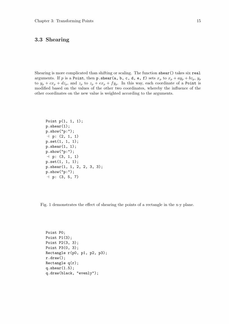
Fig. 1 demonstrates the effect of shearing the points of a rectangle in the x-y plane.
Point P0;
Point P1(3);
Point P2(3, 3);
Point P3(0, 3);
Rectangle r(p0, p1, p2, p3);
r.draw();
Rectangle q(r);
q.shear(1.5);
q.draw(black, "evenly");

Chapter 3: Transforming Points 16
P0 = Q0 = (0, 0) P1 = Q1 = (3, 0)
P2 = (3, 3)P3 = (0, 3)
r q
Q2 = (7.5, 3)Q3 = (4.5, 3)
Figure 1.
Chapter 3: Transforming Points 17
3.4 Rotating
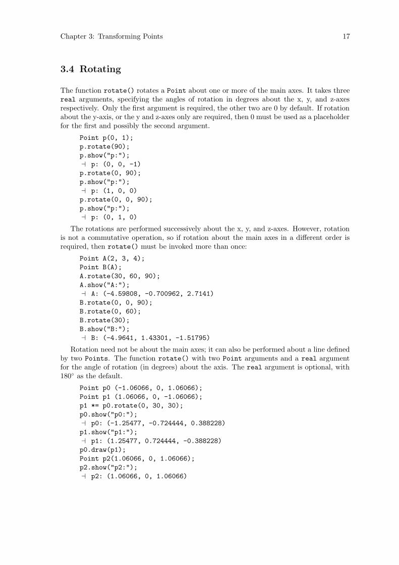
The function rotate() rotates a Point about one or more of the main axes. It takes threereal arguments, specifying the angles of rotation in degrees about the x, y, and z-axesrespectively. Only the first argument is required, the other two are 0 by default. If rotationabout the y-axis, or the y and z-axes only are required, then 0 must be used as a placeholderfor the first and possibly the second argument.
Point p(0, 1);
p.rotate(90);
p.show("p:");
a p: (0, 0, -1)
p.rotate(0, 90);
p.show("p:");
a p: (1, 0, 0)
p.rotate(0, 0, 90);
p.show("p:");
a p: (0, 1, 0)
The rotations are performed successively about the x, y, and z-axes. However, rotationis not a commutative operation, so if rotation about the main axes in a different order isrequired, then rotate() must be invoked more than once:
Point A(2, 3, 4);
Point B(A);
A.rotate(30, 60, 90);
A.show("A:");
a A: (-4.59808, -0.700962, 2.7141)
B.rotate(0, 0, 90);
B.rotate(0, 60);
B.rotate(30);
B.show("B:");
a B: (-4.9641, 1.43301, -1.51795)
Rotation need not be about the main axes; it can also be performed about a line definedby two Points. The function rotate() with two Point arguments and a real argumentfor the angle of rotation (in degrees) about the axis. The real argument is optional, with180◦ as the default.
Point p0 (-1.06066, 0, 1.06066);
Point p1 (1.06066, 0, -1.06066);
p1 *= p0.rotate(0, 30, 30);
p0.show("p0:");
a p0: (-1.25477, -0.724444, 0.388228)
p1.show("p1:");
a p1: (1.25477, 0.724444, -0.388228)
p0.draw(p1);
Point p2(1.06066, 0, 1.06066);
p2.show("p2:");
a p2: (1.06066, 0, 1.06066)

Chapter 3: Transforming Points 18
Point p3(p2);
p3.rotate(p1, p0, 45);
p3.show("p3:");
a p3 (1.09721, 1.15036, 1.17879)
Point p4(p2);
p4.rotate(p1, p0, 90);
p4.show("p4:");
a p4: (0.882625, 2.05122, 0.485242)
Point p5(p2);
p5.rotate(p1, p0, 135);
p5.show("p5:");
a p5: (0.542606, 2.17488, -0.613716)
Point p6(p2);
p6.rotate(p1, p0);
p6.show("p6:");
a p6: (0.276332, 1.44889, -1.47433)
x
y
z
p0
p1p2
p3
p4
p5
p6
Figure 2.
I have sometimes gotten erroneous results using rotate() for rotation about two Points.It’s usually worked to reverse the order of the Point arguments, or to change sign of theangle argument. I think I’ve fixed the problem, though.
Chapter 4: Transforms 19
4 Transforms
When Points are transformed using shift(), shear(), or one of the other transforma-tion functions, the world_coordinates are not modified directly. Instead, another datamember of class Point is used to store the information about the transformation, namelytransform of type class Transform. A Transform object has a single data element oftype Matrix and a number of member functions. A Matrix is simply a 4 × 4 array1 ofreals defined using typedef real Matrix[4][4]. Such a matrix suffices for performing allof the transformations (affine and perspective) possible in three-dimensional space.2 Anycombination of transformations can be represented by a single transformation matrix. Thismeans that consecutive transformations of a Point can be “saved up” and applied to itscoordinates all at once when needed, rather than updating them for each transformation.
Transforms work by performing matrix multiplication of Matrix with the homogeneousworld_coordinates of Points. If a set of homogeneous coordinates α = (x, y, z, w) and
Matrix M =
a e i mb f j nc g k od h l p
then the set of homogeneous coordinates β resulting from multiplying α and M is calculatedas follows:
β = α×M = ((xa+yb+zc+wd), (xe+yf +zg+wh), (xi+yj+zk+wl), (xm+yn+zo+wp))
Please note that each coordinate of β can be influenced by all of the coordinates of α.
Operations on matrices are very important in computer graphics applications and aredescribed in many books about computer graphics and geometry. For 3DLDF, I’ve mostlyused Huw Jones’ Computer Graphics through Key Mathematics and David Salomon’s Com-
puter Graphics and Geometric Modeling.
It is often useful to declare and use Transform objects in 3DLDF, just as it is fortransforms in Metafont. Transformations can be stored in Transforms and then be usedto transform Points by means of Point::operator*=(const Transform&).
1. Transform t;
2. t.shift(0, 1);
3. Point p(1, 0, 0);
4. p *= t;
1 It is unfortunate that the terms “array”, “matrix”, and “vector” have different meanings in C++ andin normal mathematical usage. However, in practice, these discrepancies turn out not to cause manyproblems. Stroustrup, The C++ Programming Language, § 22.4, p. 662.
2 In fact, none of the operations for transformations require all of the elements of a 4 × 4 matrix. Inmany 3D graphics programs, the matrix operations are modified to use smaller transformation matrices,which reduces the storage requirements of the program. This is a bit tricky, because the affine trans-formations and the perspective transformation use different elements of the matrix. I consider that therisk of something going wrong, possibly producing hard-to-find bugs, outweighs any benefits from savingmemory (which is usually no longer at a premium, anyway). In addition, there may be some interestingnon-affine transformations that would be worth implementing. Therefore, I’ve decided to use full 4 × 4matrices in 3DLDF.
Chapter 4: Transforms 20
5. p.show("p:");
a p: (1, 1, 0)
When a Transform is declared (line 1), it is initialized to an identity matrix. All identitymatrices are square, all of the elements of the main diagonal (upper left to lower right) are1, and all of the other elements are 0. So a 4× 4 identity matrix, as used in 3DLDF, lookslike this:
1 0 0 00 1 0 00 0 1 00 0 0 1
If a matrix A is multiplied with an identity matrix I, the result is identical to A, i.e.,A× I = A. This is the salient property of an identity matrix.
The same affine transformations are applied in the same way to Transforms as they areto Points, i.e., the functions scale(), shift(), shear(), and rotate() correspond to thePoint versions of these functions, and they take the same arguments:
Point p;
Transform t;
p.shift(3, 4, 5);
t.shift(3, 4, 5);⇒ p.transform ≡ t
p.show_transform("p:");
a p:
Transform:
0 0.707 0.707 0
-0.866 0.354 -0.354 0
-0.5 -0.612 0.612 0
0 0 0 1
t.show("t:");
a t:
0 0.707 0.707 0
-0.866 0.354 -0.354 0
-0.5 -0.612 0.612 0
0 0 0 1
4.1 Applying Transforms to Points
A Transform t is applied to a Point P using the binary *= operation(Point::operator*=(const Transform&)) which performs matrix multiplicationof P.transform by t. See Section 22.6 [Point Reference; Operators], page 124.
Point P(0, 1);
Transform t;
t.rotate(90);
t.show("t:");
a t:
Chapter 4: Transforms 21
1 0 0 0
0 0 -1 0
0 1 0 0
0 0 0 1
P *= t;
P.show_transform("P:");
a P:
Transform:
1 0 0 0
0 0 -1 0
0 1 0 0
0 0 0 1
P.show("P:");
a P: (0, 0, -1)
In the example above, there is no real need to use a Transform, since P.rotate(90)
could have been called directly. As constructions become more complex, the power ofTransforms becomes clear:
1. Point p0(0, 0, 0);
2. Point p1(10, 5, 10);
3. Point p2(16, 14, 32);
4. Point p3(25, 50, 99);
5. Point p4(12, 6, 88);
6. Transform a;
7. a.shift(2, 3, 4);
8. a.scale(1, 3, 1);
9. p2 *= p3 *= a;
10. a.rotate(p0, p1, 75);
11. p4 *= a;
12. p2.show("p2:");
a p2: (18, 51, 36)
13. p3.show("p3:");
a p3: (27, 159, 103)
14. p4.show("p4:");
a p4: (24.4647, -46.2869, 81.5353)
In this example, a is shifted and scaled, and a is applied to both in line 9. This works,because the binary operation operator*=(const Transform& t) returns t, making it pos-sible to chain invocations of *=. Following this, a is rotated 75◦ about the line through p0
and p1. Finally, all three transformations, which are stored in a, are applied to p4.
4.2 Inverting Transforms
Inversion is another operation that can be performed on Transforms. This makes it possibleto reverse the effect of a Transform, which may represent multiple transformations.
Chapter 4: Transforms 22
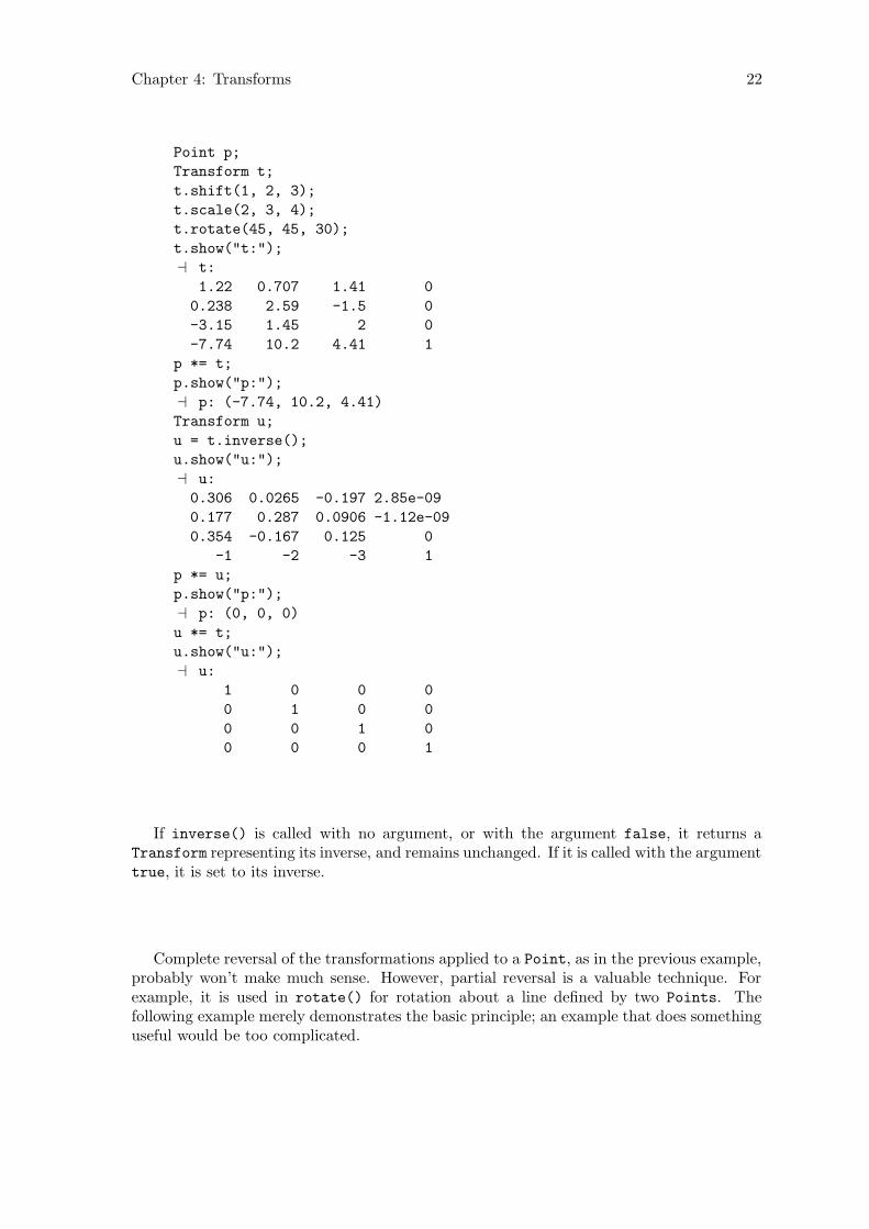
Point p;
Transform t;
t.shift(1, 2, 3);
t.scale(2, 3, 4);
t.rotate(45, 45, 30);
t.show("t:");
a t:
1.22 0.707 1.41 0
0.238 2.59 -1.5 0
-3.15 1.45 2 0
-7.74 10.2 4.41 1
p *= t;
p.show("p:");
a p: (-7.74, 10.2, 4.41)
Transform u;
u = t.inverse();
u.show("u:");
a u:
0.306 0.0265 -0.197 2.85e-09
0.177 0.287 0.0906 -1.12e-09
0.354 -0.167 0.125 0
-1 -2 -3 1
p *= u;
p.show("p:");
a p: (0, 0, 0)
u *= t;
u.show("u:");
a u:
1 0 0 0
0 1 0 0
0 0 1 0
0 0 0 1
If inverse() is called with no argument, or with the argument false, it returns aTransform representing its inverse, and remains unchanged. If it is called with the argumenttrue, it is set to its inverse.
Complete reversal of the transformations applied to a Point, as in the previous example,probably won’t make much sense. However, partial reversal is a valuable technique. Forexample, it is used in rotate() for rotation about a line defined by two Points. Thefollowing example merely demonstrates the basic principle; an example that does somethinguseful would be too complicated.

Chapter 4: Transforms 23
Transform t;
t.shift(3, 4, 5);
t.rotate(45);
t.scale(2, 2, 2);
Point p;
p *= t;
p.show("p:");
a p: (6, 12.7279, 1.41421)
t.inverse(true);
p.rotate(90, 90);
p *= t;
p.show("p:");
a p: (3.36396, -5.62132, -2.37868)
Chapter 5: Drawing and Labeling Points 24
5 Drawing and Labeling Points
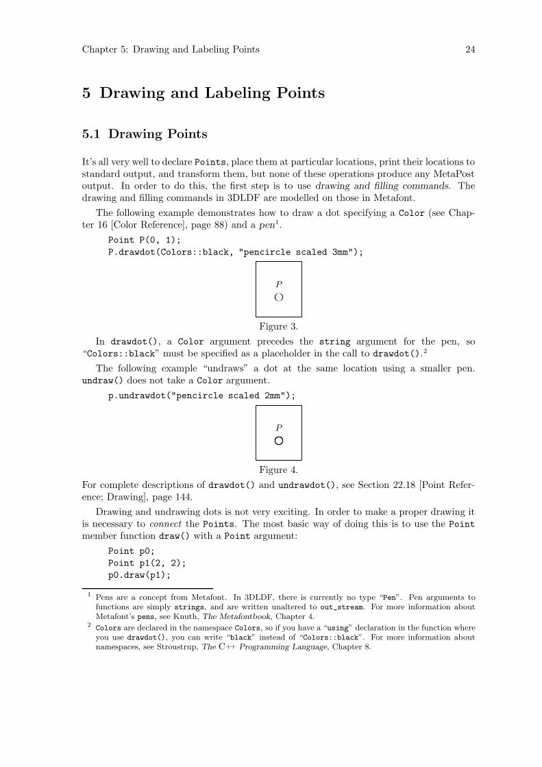
5.1 Drawing Points
It’s all very well to declare Points, place them at particular locations, print their locations tostandard output, and transform them, but none of these operations produce any MetaPostoutput. In order to do this, the first step is to use drawing and filling commands. Thedrawing and filling commands in 3DLDF are modelled on those in Metafont.
The following example demonstrates how to draw a dot specifying a Color (see Chap-ter 16 [Color Reference], page 88) and a pen1.
Point P(0, 1);
P.drawdot(Colors::black, "pencircle scaled 3mm");
P
Figure 3.
In drawdot(), a Color argument precedes the string argument for the pen, so“Colors::black” must be specified as a placeholder in the call to drawdot().2
The following example “undraws” a dot at the same location using a smaller pen.undraw() does not take a Color argument.
p.undrawdot("pencircle scaled 2mm");
P
Figure 4.
For complete descriptions of drawdot() and undrawdot(), see Section 22.18 [Point Refer-ence; Drawing], page 144.
Drawing and undrawing dots is not very exciting. In order to make a proper drawing itis necessary to connect the Points. The most basic way of doing this is to use the Point
member function draw() with a Point argument:
Point p0;
Point p1(2, 2);
p0.draw(p1);
1 Pens are a concept from Metafont. In 3DLDF, there is currently no type “Pen”. Pen arguments tofunctions are simply strings, and are written unaltered to out_stream. For more information aboutMetafont’s pens, see Knuth, The Metafontbook, Chapter 4.
2 Colors are declared in the namespace Colors, so if you have a “using” declaration in the function whereyou use drawdot(), you can write “black” instead of “Colors::black”. For more information aboutnamespaces, see Stroustrup, The C++ Programming Language, Chapter 8.
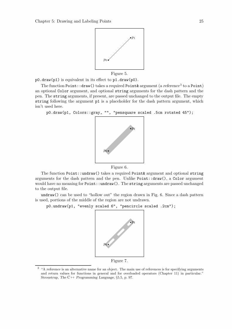
Chapter 5: Drawing and Labeling Points 25
p0
p1
Figure 5.
p0.draw(p1) is equivalent in its effect to p1.draw(p0).
The function Point::draw() takes a required Point& argument (a reference 3 to a Point)an optional Color argument, and optional string arguments for the dash pattern and thepen. The string arguments, if present, are passed unchanged to the output file. The emptystring following the argument p1 is a placeholder for the dash pattern argument, whichisn’t used here.
p0.draw(p1, Colors::gray, "", "pensquare scaled .5cm rotated 45");
p0
p1
Figure 6.
The function Point::undraw() takes a required Point& argument and optional stringarguments for the dash pattern and the pen. Unlike Point::draw(), a Color argumentwould have no meaning for Point::undraw(). The string arguments are passed unchangedto the output file.
undraw() can be used to “hollow out” the region drawn in Fig. 6. Since a dash patternis used, portions of the middle of the region are not undrawn.
p0.undraw(p1, "evenly scaled 6", "pencircle scaled .2cm");
p0
p1
Figure 7.
3 “A reference is an alternative name for an object. The main use of references is for specifying argumentsand return values for functions in general and for overloaded operators (Chapter 11) in particular.”Stroustrup, The C++ Programming Language, §5.5, p. 97.
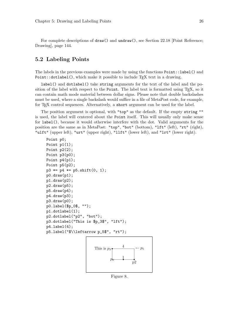
Chapter 5: Drawing and Labeling Points 26
For complete descriptions of draw() and undraw(), see Section 22.18 [Point Reference;Drawing], page 144.
5.2 Labeling Points
The labels in the previous examples were made by using the functions Point::label() andPoint::dotlabel(), which make it possible to include TEX text in a drawing.
label() and dotlabel() take string arguments for the text of the label and the po-sition of the label with respect to the Point. The label text is formatted using TEX, so itcan contain math mode material between dollar signs. Please note that double backslashesmust be used, where a single backslash would suffice in a file of MetaPost code, for example,for TEX control sequences. Alternatively, a short argument can be used for the label.
The position argument is optional, with "top" as the default. If the empty string ""
is used, the label will centered about the Point itself. This will usually only make sensefor label(), because it would otherwise interfere with the dot. Valid arguments for theposition are the same as in MetaPost: "top", "bot" (bottom), "lft" (left), "rt" (right),"ulft" (upper left), "urt" (upper right), "llft" (lower left), and "lrt" (lower right).
Point p0;
Point p1(1);
Point p2(2);
Point p3(p0);
Point p4(p1);
Point p5(p2);
p3 *= p4 *= p5.shift(0, 1);
p0.draw(p1);
p1.draw(p2);
p2.draw(p5);
p5.draw(p4);
p4.draw(p3);
p3.draw(p0);
p0.label($p_0$, "");
p1.dotlabel(1);
p2.dotlabel("p2", "bot");
p3.dotlabel("This is $p_3$", "lft");
p4.label(4);
p5.label("$\\leftarrow p_5$", "rt");
p01
p2
This is p34 ← p5
Figure 8.

Chapter 5: Drawing and Labeling Points 27
For complete descriptions of Point::label() and Point::dotlabel(), seeSection 22.19 [Points; Labelling], page 147.
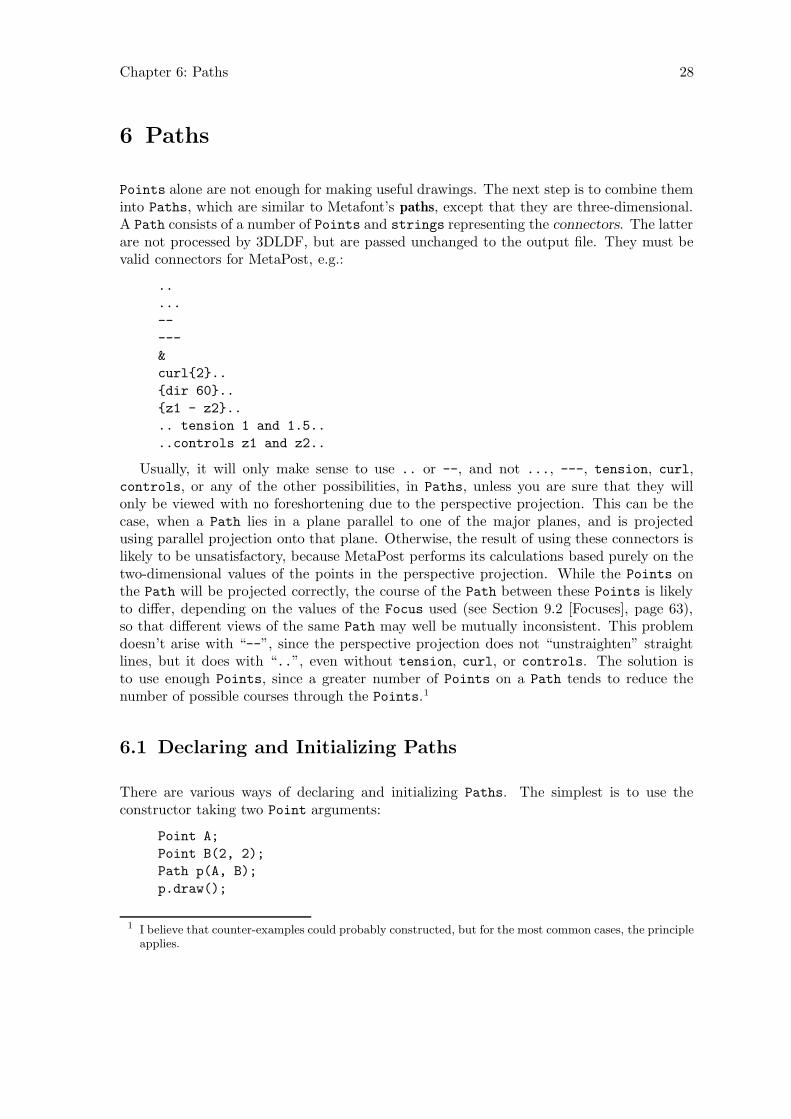
Chapter 6: Paths 28
6 Paths
Points alone are not enough for making useful drawings. The next step is to combine theminto Paths, which are similar to Metafont’s paths, except that they are three-dimensional.A Path consists of a number of Points and strings representing the connectors. The latterare not processed by 3DLDF, but are passed unchanged to the output file. They must bevalid connectors for MetaPost, e.g.:
..
...
--
---
&
curl{2}..
{dir 60}..
{z1 - z2}..
.. tension 1 and 1.5..
..controls z1 and z2..
Usually, it will only make sense to use .. or --, and not ..., ---, tension, curl,controls, or any of the other possibilities, in Paths, unless you are sure that they willonly be viewed with no foreshortening due to the perspective projection. This can be thecase, when a Path lies in a plane parallel to one of the major planes, and is projectedusing parallel projection onto that plane. Otherwise, the result of using these connectors islikely to be unsatisfactory, because MetaPost performs its calculations based purely on thetwo-dimensional values of the points in the perspective projection. While the Points onthe Path will be projected correctly, the course of the Path between these Points is likelyto differ, depending on the values of the Focus used (see Section 9.2 [Focuses], page 63),so that different views of the same Path may well be mutually inconsistent. This problemdoesn’t arise with “--”, since the perspective projection does not “unstraighten” straightlines, but it does with “..”, even without tension, curl, or controls. The solution isto use enough Points, since a greater number of Points on a Path tends to reduce thenumber of possible courses through the Points.1
6.1 Declaring and Initializing Paths
There are various ways of declaring and initializing Paths. The simplest is to use theconstructor taking two Point arguments:
Point A;
Point B(2, 2);
Path p(A, B);
p.draw();
1 I believe that counter-examples could probably constructed, but for the most common cases, the principleapplies.
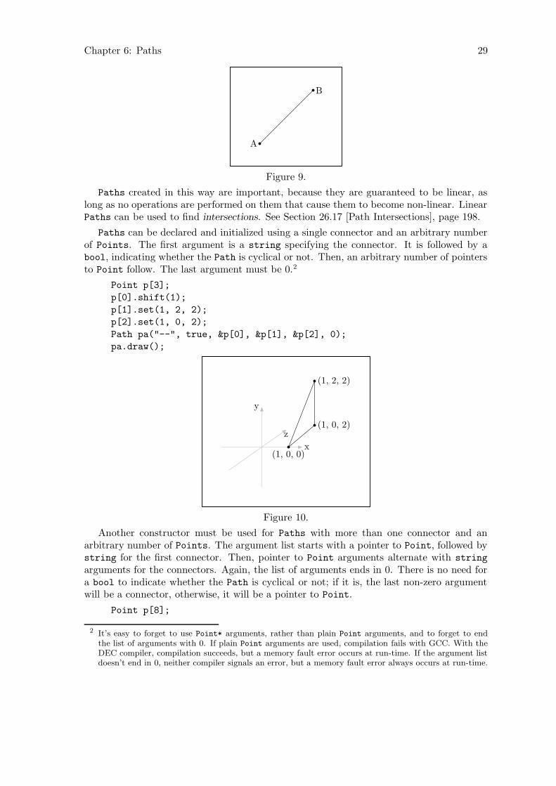
Chapter 6: Paths 29
A
B
Figure 9.
Paths created in this way are important, because they are guaranteed to be linear, aslong as no operations are performed on them that cause them to become non-linear. LinearPaths can be used to find intersections. See Section 26.17 [Path Intersections], page 198.
Paths can be declared and initialized using a single connector and an arbitrary numberof Points. The first argument is a string specifying the connector. It is followed by abool, indicating whether the Path is cyclical or not. Then, an arbitrary number of pointersto Point follow. The last argument must be 0.2
Point p[3];
p[0].shift(1);
p[1].set(1, 2, 2);
p[2].set(1, 0, 2);
Path pa("--", true, &p[0], &p[1], &p[2], 0);
pa.draw();
x
y
z
(1, 0, 0)
(1, 2, 2)
(1, 0, 2)
Figure 10.
Another constructor must be used for Paths with more than one connector and anarbitrary number of Points. The argument list starts with a pointer to Point, followed bystring for the first connector. Then, pointer to Point arguments alternate with string
arguments for the connectors. Again, the list of arguments ends in 0. There is no need fora bool to indicate whether the Path is cyclical or not; if it is, the last non-zero argumentwill be a connector, otherwise, it will be a pointer to Point.
Point p[8];
2 It’s easy to forget to use Point* arguments, rather than plain Point arguments, and to forget to endthe list of arguments with 0. If plain Point arguments are used, compilation fails with GCC. With theDEC compiler, compilation succeeds, but a memory fault error occurs at run-time. If the argument listdoesn’t end in 0, neither compiler signals an error, but a memory fault error always occurs at run-time.

Chapter 6: Paths 30
p[0].set(-2);
p[1].set(2);
p[2].set(0, 0, -2);
p[3].set(0, 0, 2);
p[4] = p[0].mediate(p[2]);
p[5] = p[2].mediate(p[1]);
p[6] = p[1].mediate(p[3]);
p[7] = p[3].mediate(p[0]);
p[4] *= p[5] *= p[6] *= p[7].shift(0, 1);
Path pa(&p[0], "..", &p[4], "...", &p[2],
"..", &p[5], "...", &p[1], "..", &p[6],
"...", &p[3], "..", &p[7], "...", 0);
pa.draw();
x
y
z
p0
p1
p2
p3p4 p5
p6p7
Figure 11.
As mentioned above (see Section 1.5.1 [Accuracy], page 7), specifying connectors is prob-lematic for three-dimensional Paths, because MetaPost ultimately calculates the “mostpleasing curve” based on the two-dimensional points in the MetaPost code written by3DLDF.3 For this reason, it’s advisable to avoid specifying ‘curl’, ‘dir’, ‘tension’ orcontrol points in connectors. The more Points a (3DLDF) Path or other object contains,the less freedom MetaPost has to determine the (MetaPost) path through them. So athree-dimensional Path or other object in 3DLDF should have enough Points to ensuresatisfactory results. The Path in Fig. 11 does not really have enough Points. It may re-quire some trial and error to determine what a sufficient number of Points is in a givencase.
Paths are very flexible, but not always convenient. 3DLDF provides a number of classesrepresenting common geometric Shapes, which will be described in subsequent sections,and I intend to add more in the course of time.
3 Knuth, The METAFONTbook, Chapter 14, p. 127.
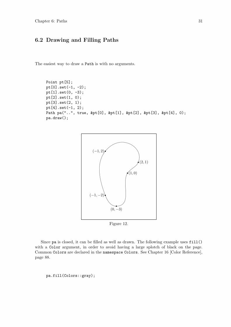
Chapter 6: Paths 31
6.2 Drawing and Filling Paths
The easiest way to draw a Path is with no arguments.
Point pt[5];
pt[0].set(-1, -2);
pt[1].set(0, -3);
pt[2].set(1, 0);
pt[3].set(2, 1);
pt[4].set(-1, 2);
Path pa("..", true, &pt[0], &pt[1], &pt[2], &pt[3], &pt[4], 0);
pa.draw();
(−1,−2)
(0,−3)
(1, 0)
(2, 1)
(−1, 2)
Figure 12.
Since pa is closed, it can be filled as well as drawn. The following example uses fill()with a Color argument, in order to avoid having a large splotch of black on the page.Common Colors are declared in the namespace Colors. See Chapter 16 [Color Reference],page 88.
pa.fill(Colors::gray);

Chapter 6: Paths 32
Figure 13.
Closed Paths can be filled and drawn, using the function filldraw(). This func-tion draws the Path using the pen specified, or MetaPost’s currentpen by default. AColor for drawing the Path can also be specified, otherwise, the default color (currentlyColors::black) is used. In addition, the Path is filled using a second Color, which canbe specified, or the background color (Colors::background_color), by default. Filling aPath using the background color causes it to hide objects that lie behind it. See Section 9.3[Surface Hiding], page 67, for a description of the surface hiding algorithm, and examples.Currently, this algorithm is quite primitive and only works for simple cases.
Point p0(-3, 0, 1);
Point p1(3, 1, 1);
p0.draw(p1);
pa.filldraw();
(−3, 0, 1)
(3, 1, 1)
Figure 14.
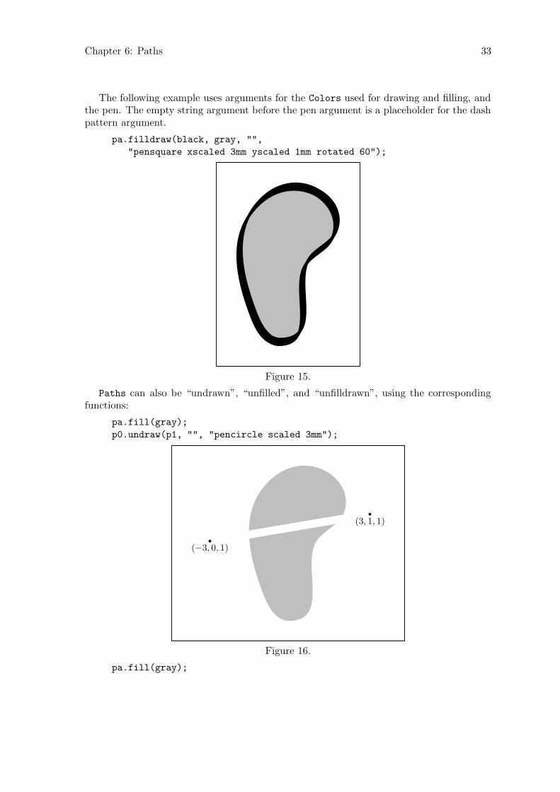
Chapter 6: Paths 33
The following example uses arguments for the Colors used for drawing and filling, andthe pen. The empty string argument before the pen argument is a placeholder for the dashpattern argument.
pa.filldraw(black, gray, "",
"pensquare xscaled 3mm yscaled 1mm rotated 60");
Figure 15.
Paths can also be “undrawn”, “unfilled”, and “unfilldrawn”, using the correspondingfunctions:
pa.fill(gray);
p0.undraw(p1, "", "pencircle scaled 3mm");
(−3, 0, 1)
(3, 1, 1)
Figure 16.
pa.fill(gray);
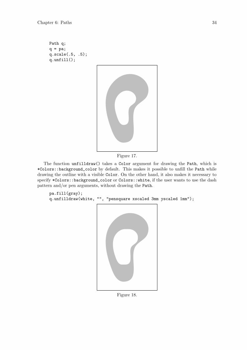
Chapter 6: Paths 34
Path q;
q = pa;
q.scale(.5, .5);
q.unfill();
Figure 17.
The function unfilldraw() takes a Color argument for drawing the Path, which is*Colors::background_color by default. This makes it possible to unfill the Path whiledrawing the outline with a visible Color. On the other hand, it also makes it necessary tospecify *Colors::background_color or Colors::white, if the user wants to use the dashpattern and/or pen arguments, without drawing the Path.
pa.fill(gray);
q.unfilldraw(white, "", "pensquare xscaled 3mm yscaled 1mm");
Figure 18.
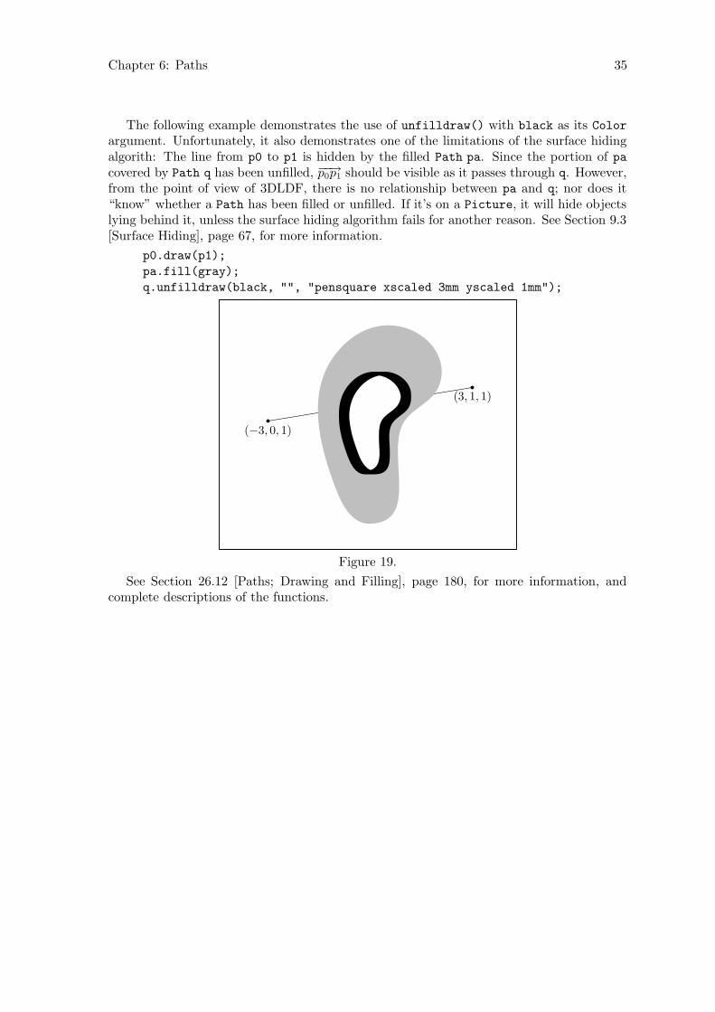
Chapter 6: Paths 35
The following example demonstrates the use of unfilldraw() with black as its Color
argument. Unfortunately, it also demonstrates one of the limitations of the surface hidingalgorith: The line from p0 to p1 is hidden by the filled Path pa. Since the portion of pacovered by Path q has been unfilled, −−→p0p1 should be visible as it passes through q. However,from the point of view of 3DLDF, there is no relationship between pa and q; nor does it“know” whether a Path has been filled or unfilled. If it’s on a Picture, it will hide objectslying behind it, unless the surface hiding algorithm fails for another reason. See Section 9.3[Surface Hiding], page 67, for more information.
p0.draw(p1);
pa.fill(gray);
q.unfilldraw(black, "", "pensquare xscaled 3mm yscaled 1mm");
(−3, 0, 1)
(3, 1, 1)
Figure 19.
See Section 26.12 [Paths; Drawing and Filling], page 180, for more information, andcomplete descriptions of the functions.

Chapter 7: Plane Figures 36
7 Plane Figures
3DLDF currently includes the following classes representing plane geometric figures:Polygon, Reg_Cl_Plane_Curve (“Regular Closed Plane Curve”), Reg_Polygon (“RegularPolygon”), Rectangle, Ellipse and Circle. Polygon and Reg_Cl_Plane_Curve arederived from Path, Reg_Polygon and Rectangle are derived from Polygon, and Ellipse
and Circle are derived from Reg_Cl_Plane_Curve. Polygon and Reg_Cl_Plane_Curve
are meant to be used as base classes only, so objects of these types should normally neverbe declared.
Since Reg_Polygon, Rectangle, Ellipse, and Circle all ultimately derive from Path,they are really just special kinds of Path. In particular, they inherit their drawing andfilling functions from Path, and their transformation functions take the same arguments asthe Path versions. They also have constructors and setting functions that work in a similarway, with a few minor differences, to account for their different natures. See Chapter 27[Polygon Reference], page 199, Chapter 29 [Rectangle Reference], page 211, Chapter 31[Ellipse Reference], page 222, and Chapter 32 [Circle Reference], page 238, for completeinformation on these classes.
7.1 Regular Polygons
The following example creates a pentagon in the x-z plane, centered about the origin, whoseenclosing circle has a radius equal to 3cm.
default_focus.set(2, 3, -10, 2, 3, 10, 10);
Reg_Polygon p(origin, 5, 3);
p.draw();
x
y
z
Figure 20.
Three additional arguments cause the pentagon to be rotated about the x, y, and z axesby the amount indicated. In this example, it’s rotated 90◦ about the x-axis, so that it comesto lie in the x-y plane:
Reg_Polygon p(origin, 5, 3, 90);
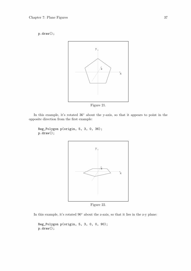
Chapter 7: Plane Figures 37
p.draw();
x
y
z
Figure 21.
In this example, it’s rotated 36◦ about the y-axis, so that it appears to point in theopposite direction from the first example:
Reg_Polygon p(origin, 5, 3, 0, 36);
p.draw();
x
y
z
Figure 22.
In this example, it’s rotated 90◦ about the z-axis, so that it lies in the z-y plane:
Reg_Polygon p(origin, 5, 3, 0, 0, 90);
p.draw();

Chapter 7: Plane Figures 38
x
y
z
Figure 23.
In this example, it’s rotated 45◦ about the x, y, and z-axes in that order:
Reg_Polygon p(origin, 5, 3, 45, 45, 45);
p.draw();
x
y
z
Figure 24.
Reg_Polygons need not be centered about the origin. If another Point pt is used asthe first argument, the Reg_Polygon is first created with its center at the origin, then thespecified rotations, if any, are performed. Finally, the Reg_Polygon is shifted such that itscenter comes to lie on pt:
Point P(-2, 1, 1);
Reg_Polygon hex(P, 6, 4, 60, 30, 30);
hex.draw();
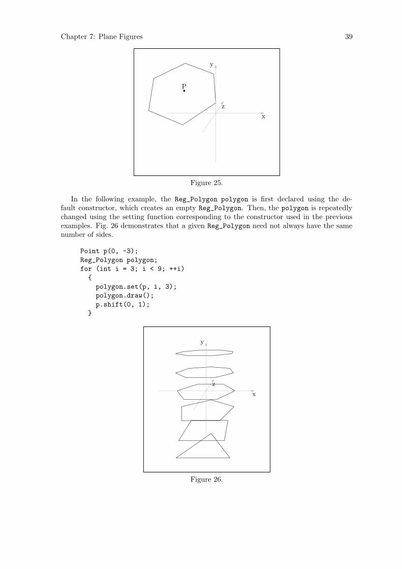
Chapter 7: Plane Figures 39
P
x
y
z
Figure 25.
In the following example, the Reg_Polygon polygon is first declared using the de-fault constructor, which creates an empty Reg_Polygon. Then, the polygon is repeatedlychanged using the setting function corresponding to the constructor used in the previousexamples. Fig. 26 demonstrates that a given Reg_Polygon need not always have the samenumber of sides.
Point p(0, -3);
Reg_Polygon polygon;
for (int i = 3; i < 9; ++i)
{
polygon.set(p, i, 3);
polygon.draw();
p.shift(0, 1);
}
x
y
z
Figure 26.

Chapter 7: Plane Figures 40
7.2 Rectangles
A Rectangle can be constructed in the x-z plane by specifying a center Point, the width,and the height:
Rectangle r(origin, 2, 3);
r.draw();
x
y
z
Figure 27.
Three additional arguments can be used to specify rotation about the x, y, and z-axesrespectively:
Rectangle r(origin, 2, 3, 30, 45, 15);
r.draw();
x
y
z
Figure 28.
If a Point p other than the origin is specified as the center of the Rectangle, the latteris first created in the x-z plane, centered about the origin, as above. Then, any rotationsspecified are performed. Finally, the Rectangle is shifted such that its center comes to lieat p:

Chapter 7: Plane Figures 41
Point p0(.5, 1, 3);
Rectangle r(p0, 4, 2, 30, 30, 30);
r.draw();
p0p0 = (0.5, 1, 3)
x
y
z
Figure 29.
This constructor has a corresponding setting function:
Rectangle r;
for (int i = 0; i < 180; i += 30)
{
r.set(origin, 4, 2, i);
r.draw();
}
x
y
z
Figure 30.
Rectangles can also be specified using four Points as arguments, whereby they mustbe ordered so that they are contiguous in the resulting Rectangle:
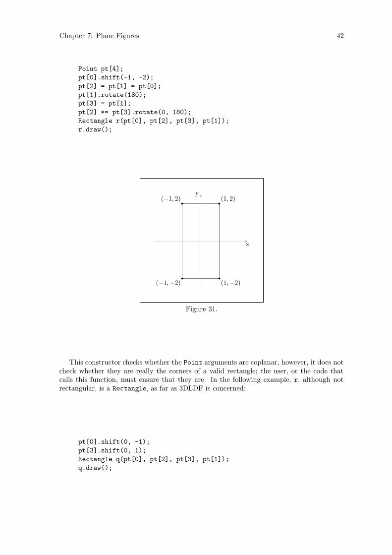
Chapter 7: Plane Figures 42
Point pt[4];
pt[0].shift(-1, -2);
pt[2] = pt[1] = pt[0];
pt[1].rotate(180);
pt[3] = pt[1];
pt[2] *= pt[3].rotate(0, 180);
Rectangle r(pt[0], pt[2], pt[3], pt[1]);
r.draw();
(−1,−2) (1,−2)
(1, 2)(−1, 2)
x
y
Figure 31.
This constructor checks whether the Point arguments are coplanar, however, it does notcheck whether they are really the corners of a valid rectangle; the user, or the code thatcalls this function, must ensure that they are. In the following example, r, although notrectangular, is a Rectangle, as far as 3DLDF is concerned:
pt[0].shift(0, -1);
pt[3].shift(0, 1);
Rectangle q(pt[0], pt[2], pt[3], pt[1]);
q.draw();
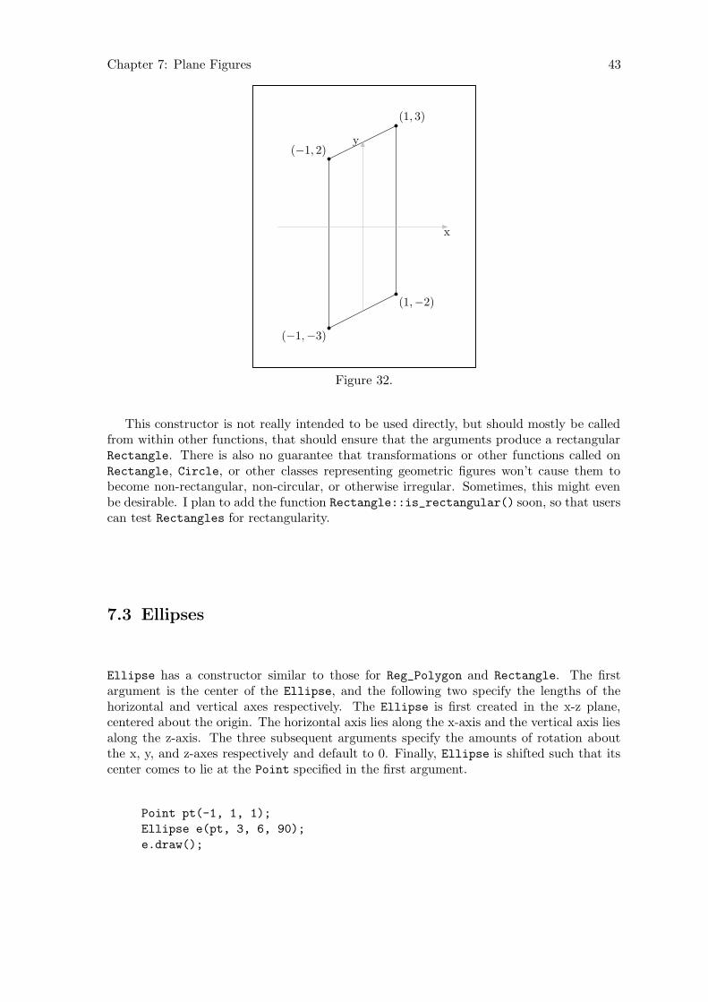
Chapter 7: Plane Figures 43
(−1,−3)
(1,−2)
(1, 3)
(−1, 2)
x
y
Figure 32.
This constructor is not really intended to be used directly, but should mostly be calledfrom within other functions, that should ensure that the arguments produce a rectangularRectangle. There is also no guarantee that transformations or other functions called onRectangle, Circle, or other classes representing geometric figures won’t cause them tobecome non-rectangular, non-circular, or otherwise irregular. Sometimes, this might evenbe desirable. I plan to add the function Rectangle::is_rectangular() soon, so that userscan test Rectangles for rectangularity.
7.3 Ellipses
Ellipse has a constructor similar to those for Reg_Polygon and Rectangle. The firstargument is the center of the Ellipse, and the following two specify the lengths of thehorizontal and vertical axes respectively. The Ellipse is first created in the x-z plane,centered about the origin. The horizontal axis lies along the x-axis and the vertical axis liesalong the z-axis. The three subsequent arguments specify the amounts of rotation aboutthe x, y, and z-axes respectively and default to 0. Finally, Ellipse is shifted such that itscenter comes to lie at the Point specified in the first argument.
Point pt(-1, 1, 1);
Ellipse e(pt, 3, 6, 90);
e.draw();
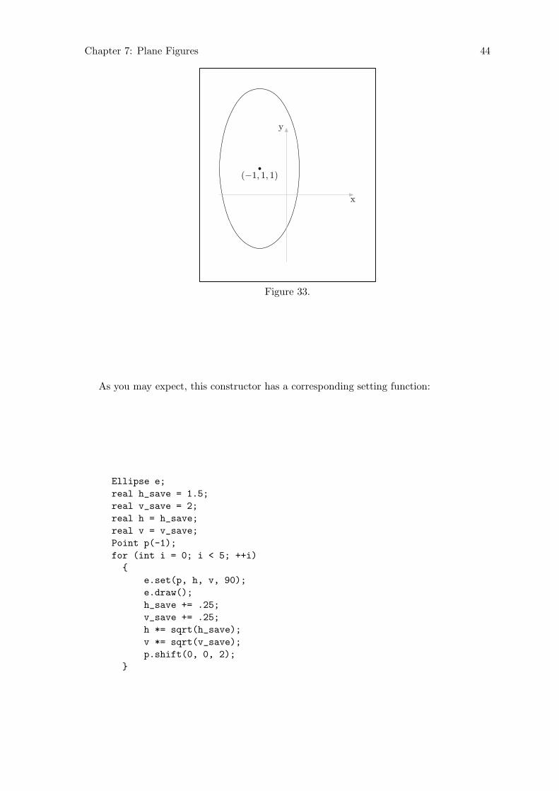
Chapter 7: Plane Figures 44
(−1, 1, 1)
x
y
Figure 33.
As you may expect, this constructor has a corresponding setting function:
Ellipse e;
real h_save = 1.5;
real v_save = 2;
real h = h_save;
real v = v_save;
Point p(-1);
for (int i = 0; i < 5; ++i)
{
e.set(p, h, v, 90);
e.draw();
h_save += .25;
v_save += .25;
h *= sqrt(h_save);
v *= sqrt(v_save);
p.shift(0, 0, 2);
}

Chapter 7: Plane Figures 45
x
y
z
Figure 34.
7.4 Circles
Circles are constructed just like Ellipses, except that the vertical and horizontal axesare per definition the same, so there’s only one argument for the diameter, instead of twofor the horizontal and vertical axes:
Point P(0, 2, 1);
Circle c(P, 3.5, 90, 90);
c.draw();
(0, 2, 1)y
z
Figure 35.

Chapter 7: Plane Figures 46
This constructor, too, has a corresponding setting function:
Circle c;
Point p(-1, 0, 5);
for (int i = 0; i < 16; ++i)
{
c.set(p, 5, i * 22.5, 0, 0, 64);
c.draw();
}
p
x
y
z
Figure 36.
In the preceding example, the last argument to set(), namely “64”, is for the numberof Points used for constructing the perimeter of the Circle. The default value is 16,however, if it is used, foreshortening distorts the most nearly horizontal Circle. Increasingthe number of points used improves its appearance. However, there may be a limit to howmuch improvement is possible. See Section 1.5.1 [Accuracy], page 7.

Chapter 8: Solid Figures 47
8 Solid Figures
8.1 Cuboids
A cuboid is a solid figure consisting of six rectangular faces that meet at right angles. Acube is a special form of cuboid, whose faces are all squares. The constructor for the classCuboid follows the pattern familiar from the constructors for the plane figures: The firstargument is the center of the Cuboid, followed by three real arguments for the height,width, and depth, and then three more real arguments for the angles of rotation about thex, y, and z-axes. The Cuboid is first constructed with its center at the origin. Its width,height, and depth are measured along the x, y, and z-axes respectively. If rotations arespecified, it is rotated about the x, y, z-axes in that order. Finally, it is shifted such thatits center comes to lie on its Point argument, if the latter is not the origin.
If the width, height, and depth arguments are equal, the Cuboid is a cube:
Cuboid c0(origin, 3, 3, 3, 0, 30);
c0.draw();
Figure 37.
In the following example, the Cuboid is “filldrawn”, so that the lines dilineating thehidden surfaces of the Cuboid are covered.
Cuboid c1(origin, 3, 4, 5, 0, 30);
c1.filldraw();
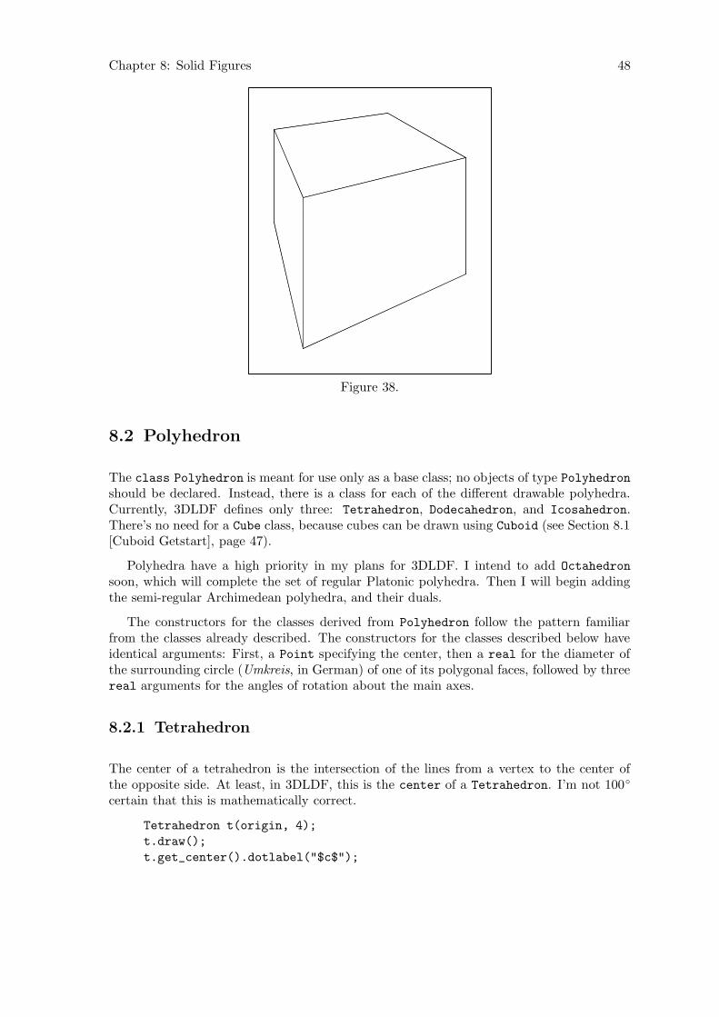
Chapter 8: Solid Figures 48
Figure 38.
8.2 Polyhedron
The class Polyhedron is meant for use only as a base class; no objects of type Polyhedronshould be declared. Instead, there is a class for each of the different drawable polyhedra.Currently, 3DLDF defines only three: Tetrahedron, Dodecahedron, and Icosahedron.There’s no need for a Cube class, because cubes can be drawn using Cuboid (see Section 8.1[Cuboid Getstart], page 47).
Polyhedra have a high priority in my plans for 3DLDF. I intend to add Octahedron
soon, which will complete the set of regular Platonic polyhedra. Then I will begin addingthe semi-regular Archimedean polyhedra, and their duals.
The constructors for the classes derived from Polyhedron follow the pattern familiarfrom the classes already described. The constructors for the classes described below haveidentical arguments: First, a Point specifying the center, then a real for the diameter ofthe surrounding circle (Umkreis, in German) of one of its polygonal faces, followed by threereal arguments for the angles of rotation about the main axes.
8.2.1 Tetrahedron
The center of a tetrahedron is the intersection of the lines from a vertex to the center ofthe opposite side. At least, in 3DLDF, this is the center of a Tetrahedron. I’m not 100◦
certain that this is mathematically correct.
Tetrahedron t(origin, 4);
t.draw();
t.get_center().dotlabel("$c$");

Chapter 8: Solid Figures 49
c
Figure 39.
8.2.2 Dodecahedron
A dodecahedron has 12 similar regular pentagonal faces. The following examples show thesame Dodecahedron using different projections:
default_focus.set(2, 5, -10, 2, 5, 10, 10);
Dodecahedron d(origin, 3);
d.draw();
Parallel projection, x-y plane
Figure 40.
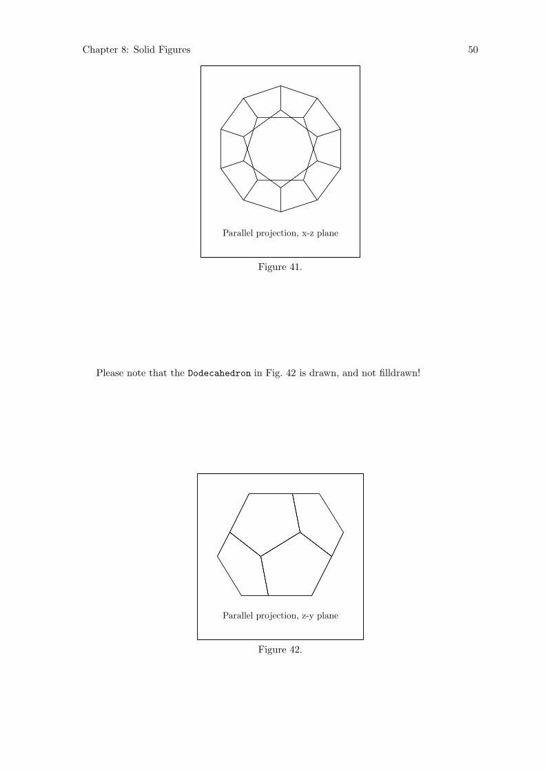
Chapter 8: Solid Figures 50
Parallel projection, x-z plane
Figure 41.
Please note that the Dodecahedron in Fig. 42 is drawn, and not filldrawn!
Parallel projection, z-y plane
Figure 42.

Chapter 8: Solid Figures 51
Perspective projection
Figure 43.
In Fig. 44, d is filldrawn. In this case, the surface hiding algorithm has worked properly.See Section 9.3 [Surface Hiding], page 67.
Perspective projection
Figure 44.
8.2.3 Icosahedron
An icosahedron has 20 similar regular triangular faces. The following examples show thesame Icosahedron using different projections:
default_focus.set(3, 0, -10, 2, 0, 10, 10);
Icosahedron i(origin, 3);
i.draw();
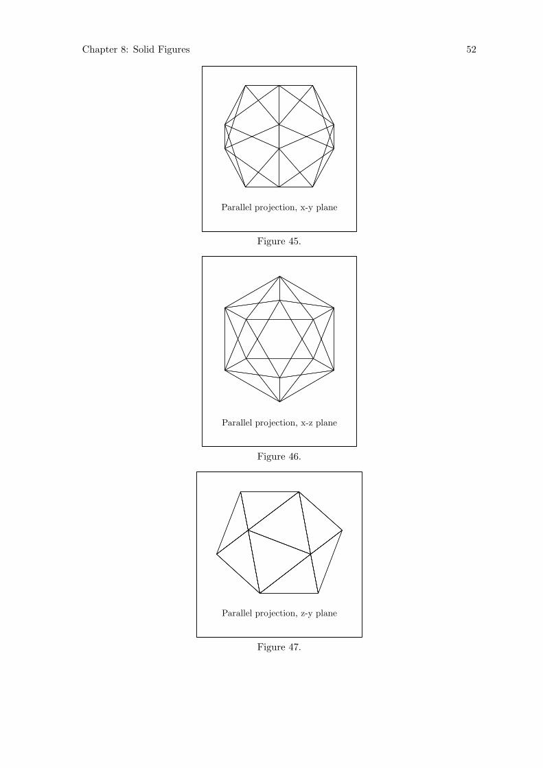
Chapter 8: Solid Figures 52
Parallel projection, x-y plane
Figure 45.
Parallel projection, x-z plane
Figure 46.
Parallel projection, z-y plane
Figure 47.
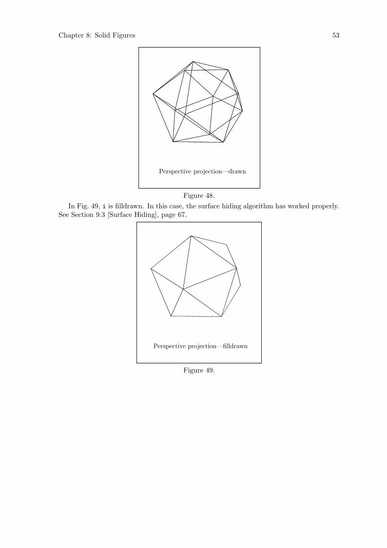
Chapter 8: Solid Figures 53
Perspective projection—drawn
Figure 48.
In Fig. 49, i is filldrawn. In this case, the surface hiding algorithm has worked properly.See Section 9.3 [Surface Hiding], page 67.
Perspective projection—filldrawn
Figure 49.
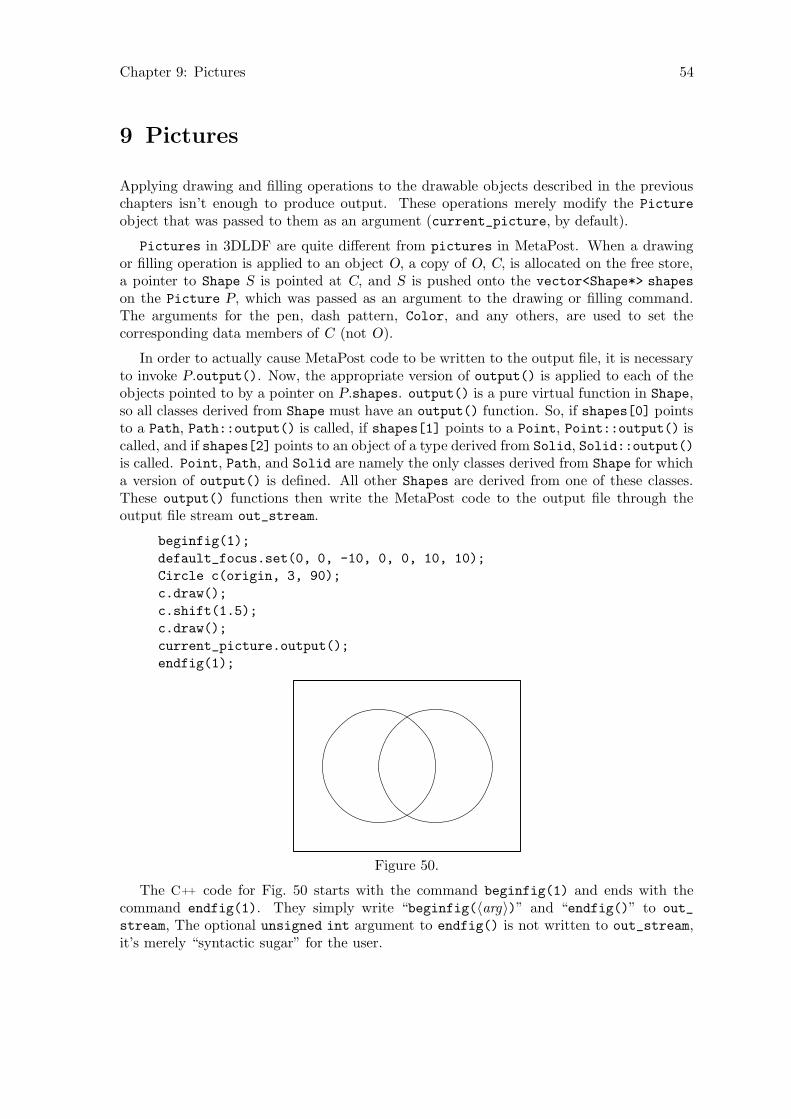
Chapter 9: Pictures 54
9 Pictures
Applying drawing and filling operations to the drawable objects described in the previouschapters isn’t enough to produce output. These operations merely modify the Picture
object that was passed to them as an argument (current_picture, by default).
Pictures in 3DLDF are quite different from pictures in MetaPost. When a drawingor filling operation is applied to an object O, a copy of O, C, is allocated on the free store,a pointer to Shape S is pointed at C, and S is pushed onto the vector<Shape*> shapes
on the Picture P, which was passed as an argument to the drawing or filling command.The arguments for the pen, dash pattern, Color, and any others, are used to set thecorresponding data members of C (not O).
In order to actually cause MetaPost code to be written to the output file, it is necessaryto invoke P.output(). Now, the appropriate version of output() is applied to each of theobjects pointed to by a pointer on P.shapes. output() is a pure virtual function in Shape,so all classes derived from Shape must have an output() function. So, if shapes[0] pointsto a Path, Path::output() is called, if shapes[1] points to a Point, Point::output() iscalled, and if shapes[2] points to an object of a type derived from Solid, Solid::output()is called. Point, Path, and Solid are namely the only classes derived from Shape for whicha version of output() is defined. All other Shapes are derived from one of these classes.These output() functions then write the MetaPost code to the output file through theoutput file stream out_stream.
beginfig(1);
default_focus.set(0, 0, -10, 0, 0, 10, 10);
Circle c(origin, 3, 90);
c.draw();
c.shift(1.5);
c.draw();
current_picture.output();
endfig(1);
Figure 50.
The C++ code for Fig. 50 starts with the command beginfig(1) and ends with thecommand endfig(1). They simply write “beginfig(〈arg〉)” and “endfig()” to out_
stream, The optional unsigned int argument to endfig() is not written to out_stream,it’s merely “syntactic sugar” for the user.
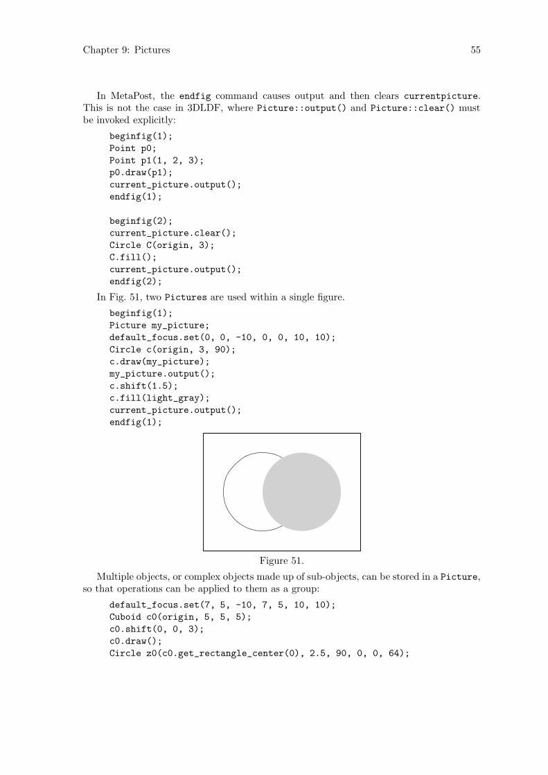
Chapter 9: Pictures 55
In MetaPost, the endfig command causes output and then clears currentpicture.This is not the case in 3DLDF, where Picture::output() and Picture::clear() mustbe invoked explicitly:
beginfig(1);
Point p0;
Point p1(1, 2, 3);
p0.draw(p1);
current_picture.output();
endfig(1);
beginfig(2);
current_picture.clear();
Circle C(origin, 3);
C.fill();
current_picture.output();
endfig(2);
In Fig. 51, two Pictures are used within a single figure.
beginfig(1);
Picture my_picture;
default_focus.set(0, 0, -10, 0, 0, 10, 10);
Circle c(origin, 3, 90);
c.draw(my_picture);
my_picture.output();
c.shift(1.5);
c.fill(light_gray);
current_picture.output();
endfig(1);
Figure 51.
Multiple objects, or complex objects made up of sub-objects, can be stored in a Picture,so that operations can be applied to them as a group:
default_focus.set(7, 5, -10, 7, 5, 10, 10);
Cuboid c0(origin, 5, 5, 5);
c0.shift(0, 0, 3);
c0.draw();
Circle z0(c0.get_rectangle_center(0), 2.5, 90, 0, 0, 64);
Chapter 9: Pictures 56
z0.draw();
Circle z1(z0);
z1.shift(0, 0, -1);
z1.draw();
int i;
int j = z0.get_size();
for (i = 0; i < 8; ++i)
z0.get_point(i * j/8).draw(z1.get_point(i * j/8));
Cuboid c1(c0.get_rectangle_center(4), 5, 3, 3);
c1.shift(0, 2.5);
c1.draw();
Rectangle r0 = *c1.get_rectangle_ptr(3);
Point p[10];
for (i = 0; i < 4; ++i)
p[i] = r0.get_point(i);
p[4] = r0.get_mid_point(0);
p[5] = r0.get_mid_point(2);
p[6] = p[4].mediate(p[5], 2/3.0);
Circle z2(p[6], 2, 90, 90, 0, 16);
z2.draw();
Circle z3 = z2;
z3.shift(3);
z3.draw();
j = z2.get_size();
for (i = 0; i < 8; ++i)
z2.get_point(i * j/8).draw(z3.get_point(i * j/8));
p[7] = c0.get_rectangle_center(2);
p[7].shift(-4);
p[8] = c0.get_rectangle_center(3);
p[8].shift(4);
current_picture.output();
current_picture.rotate(45, 45);
current_picture.shift(10, 0, 3);
current_picture.output();
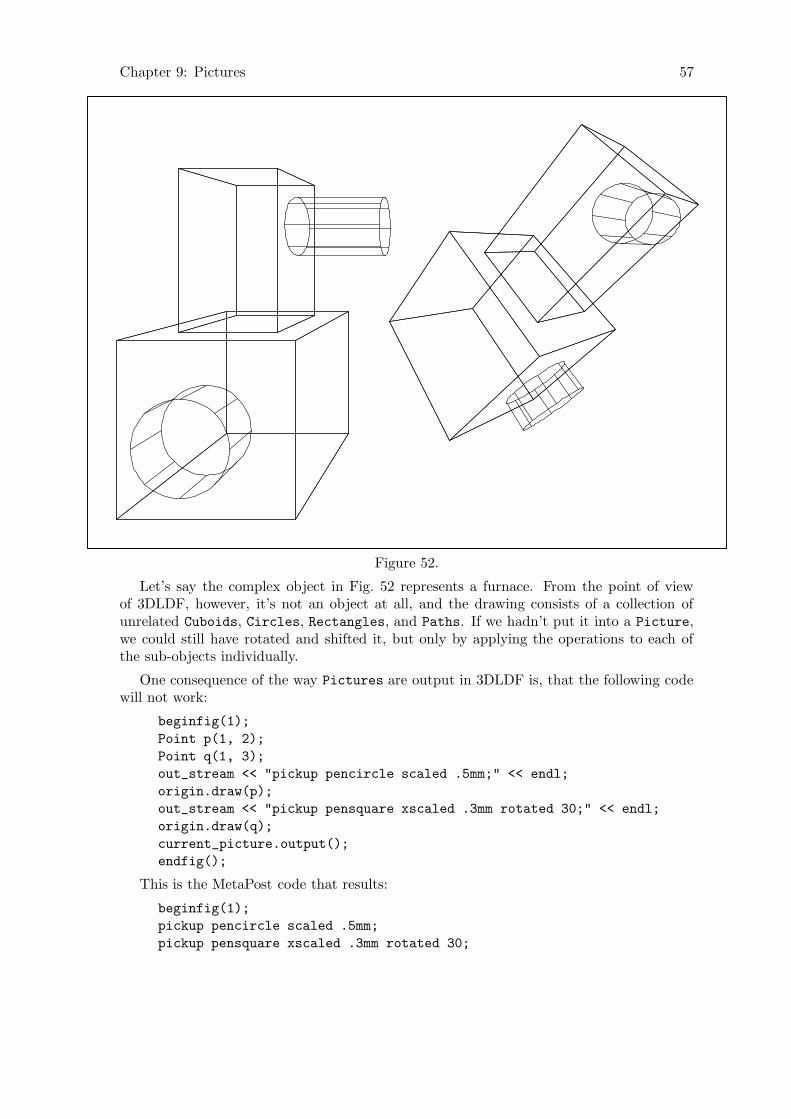
Chapter 9: Pictures 57
Figure 52.
Let’s say the complex object in Fig. 52 represents a furnace. From the point of viewof 3DLDF, however, it’s not an object at all, and the drawing consists of a collection ofunrelated Cuboids, Circles, Rectangles, and Paths. If we hadn’t put it into a Picture,we could still have rotated and shifted it, but only by applying the operations to each ofthe sub-objects individually.
One consequence of the way Pictures are output in 3DLDF is, that the following codewill not work:
beginfig(1);
Point p(1, 2);
Point q(1, 3);
out_stream << "pickup pencircle scaled .5mm;" << endl;
origin.draw(p);
out_stream << "pickup pensquare xscaled .3mm rotated 30;" << endl;
origin.draw(q);
current_picture.output();
endfig();
This is the MetaPost code that results:
beginfig(1);
pickup pencircle scaled .5mm;
pickup pensquare xscaled .3mm rotated 30;
Chapter 9: Pictures 58
draw (0.000000cm, -3.000000cm) -- (1.000000cm, -1.000000cm);
draw (0.000000cm, -3.000000cm) -- (1.000000cm, 0.000000cm);
endfig;
It’s perfectly legitimate to write raw MetaPost code to out_stream, as in lines 4 and6 of this example. However, the draw() commands do not cause any output to out_
stream. The MetaPost drawing commands are written to out_stream when current_
picture.output() is called. Therefore, the pickup commands are “bunched up” beforethe drawing commands. In this example, setting currentpen to pencircle scaled .5mm
has no effect, because it is immediately reset to pensquare xscaled .3mm rotated 30 inthe MetaPost code, before the draw commands. It is not possible to change currentpen inthis way within a Picture. Since the draw() commands in the 3DLDF code didn’t specifya pen argument, currentpen with its final value is used for both of the MetaPost draw
commands. For any given invocation of Picture::output(), there can only be one valueof currentpen. All other pens must be passed as arguments to the drawing commands.
9.1 Projections
In order for a 3D graphic program to be useful, it must be able to make two-dimensionalprojections of its three-dimensional constructions so that they can be displayed on computerscreens and printed out. These are some of the possible projections:
• Parallel projection onto one of the major planesThese projections are trivial, and can be performed by 3DLDF. They are dis-cussed in the following section.
• Parallel projection onto another planeI haven’t programmed these projections yet, but they might be useful, so Iprobably will, when I get around to it.
• The perspective projectionThis is the projection most people think of, when they think of 3D-graphics. Itis discussed in detail in Section 9.1.2 [The Perspective Projection], page 60.
• The isometric and axonometric projectionsThese projections are important for engineering and drafting. I have not yetimplemented them in 3DLDF, but they are on my list of “Things To Do”.
The function Picture::output() takes a const unsigned short argument specifyingthe projection to be used. The user should probably avoid using explicit unsigned shorts,but should use the constants defined for this purpose in the namespace Projections.1 Theconstants are PERSP, PARALLEL_X_Y, PARALLEL_X_Z, PARALLEL_Z_Y, AXON, and ISO. Thelatter two should not be used, because the axonometric and isometric projections have notyet been implemented.
9.1.1 Parallel Projections
When a Picture is projected onto the x-y plane, the x and y-values from the world_
coordinates of the Points belonging to the objects on the Picture are copied to their
1 Namespaces are described in Stroustrup, The C++ Programming Language, Chapter 8.

Chapter 9: Pictures 59
projective_coordinates, which are used in the MetaPost code written to out_stream.If a Picture p contains an object in the x-y plane, or in a plane parallel to the x-y plane,then the result of p.output(Projections::PARALLEL_X_Y) is more-or-less equivalent tojust using MetaPost without 3DLDF.
Rectangle r(origin, 3, 3, 90);
Circle c(origin, 3, 90);
c *= r.shift(0, 0, 5);
r.draw();
c.draw();
current_picture.output(Projections::PARALLEL_X_Y);
Figure 53.
If the objects do not lie in the x-y plane, or a plane parallel to the x-y plane, then theprojection will be distorted:
current_picture.output(Projections::PARALLEL_X_Y);
Figure 54.
Picture::output() can be called with an additional real argument factor for magni-fying or shrinking the Picture.
Rectangle r(origin, 4, 4, 90, 60);
Circle c(origin, 4, 90, 60);
c *= r.shift(0, 0, 5);
r.filldraw(black, gray);
c.unfilldraw(black);
current_picture.output(Projections::PARALLEL_X_Y, .5);
current_picture.shift(2.5);
current_picture.output(Projections::PARALLEL_X_Y);

Chapter 9: Pictures 60
current_picture.shift(1);
current_picture.output(Projections::PARALLEL_X_Y, 2);
.5× Normal size 2×
Figure 55.
Parallel projection onto the x-z and z-y planes are completely analogous to parallelprojection onto the x-y plane.
9.1.2 The Perspective Projection
The perspective projection obeys the laws of linear perspective. In 3DLDF, it is performedby means of a transformation, whose effect is, to the best of my knowledge, exactly equiv-alent to the result of a perspective projection done by hand using vanishing points andrulers.
It is very helpful to the artist to understand the laws of linear perspective, and to knowhow to make a perspective drawing by hand.2 However, it is a very tedious and error-proneprocedure (I know, I’ve done it). One of my main motivations for writing 3DLDF was so Iwouldn’t have to do it anymore.
Fig. 56 shows a perspective construction, the way it could be done by hand. The pointof view, or focus is located 6cm from the picture plane, and 4cm above the ground (or x-z)plane at the point (0, 4, -6). The rectangle R lies in the ground plane, with the point r0
at (2, 0, 1.5). The right side of R, with length = 2 cm lies at an angle of 40 to the groundline, which corresponds to the intersection line of the ground plane with the picture plane,and the left side, with length = 5 cm, at an angle of 90◦ − 40◦ = 50◦ to the ground line.
2 There are many books on linear perspective for artists. I’ve found Gwen White’s Perspective. A Guide
for Artists, Architects and Designers to be particularly good. Vredeman de Vries, Perspective containsbeautiful examples of perspective constructions.
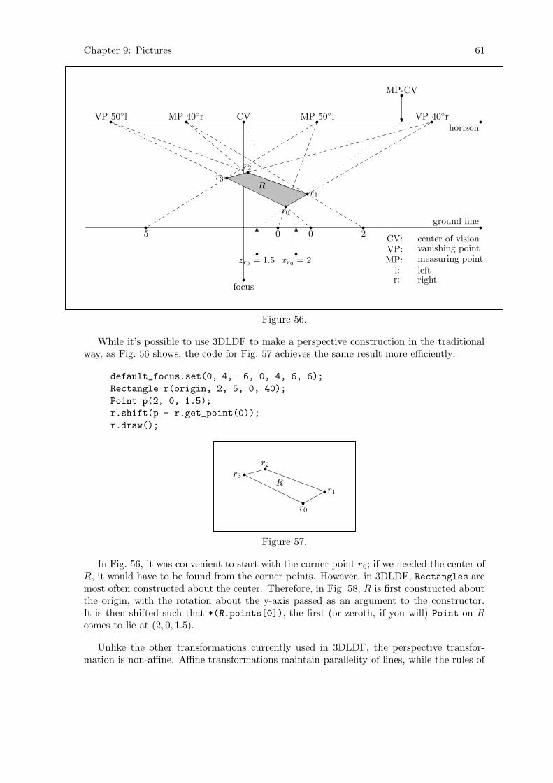
Chapter 9: Pictures 61
focus
CVhorizon
ground line
VP 40◦rMP 40◦rVP 50◦l MP 50◦l
MP-CV
xr0= 2zr0
= 1.5
r0
0 2
r1
05
r3
r2
R
CV: center of visionVP: vanishing pointMP: measuring point
l: leftr: right
Figure 56.
While it’s possible to use 3DLDF to make a perspective construction in the traditionalway, as Fig. 56 shows, the code for Fig. 57 achieves the same result more efficiently:
default_focus.set(0, 4, -6, 0, 4, 6, 6);
Rectangle r(origin, 2, 5, 0, 40);
Point p(2, 0, 1.5);
r.shift(p - r.get_point(0));
r.draw();
r0
r1
r2
r3
R
Figure 57.
In Fig. 56, it was convenient to start with the corner point r0; if we needed the center ofR, it would have to be found from the corner points. However, in 3DLDF, Rectangles aremost often constructed about the center. Therefore, in Fig. 58, R is first constructed aboutthe origin, with the rotation about the y-axis passed as an argument to the constructor.It is then shifted such that *(R.points[0]), the first (or zeroth, if you will) Point on Rcomes to lie at (2, 0, 1.5).
Unlike the other transformations currently used in 3DLDF, the perspective transfor-mation is non-affine. Affine transformations maintain parallelity of lines, while the rules of

Chapter 9: Pictures 62
perspective state that parallel lines, with one exception, appear to recede toward a vanishing
point.3
In Fig. 56, the lines −−→r0r1 and −−→r3r2 appear to vanish toward the right-hand 40◦ vanishingpoint, while −−→r0r3 and −−→r1r2 appear to vanish toward the left-hand 50◦ vanishing point. Thelower the angle of a vanishing point, the further away it is from the center of vision, asFig. 58 shows:
focus
CV
horizon
ground line
VP 20◦VP 30◦VP 40◦VP 50◦
VP 60◦
VP 70◦
VP 80◦
VP 0.5◦ (x = 572.943cm)
VP 5◦ (x = 57.1503cm)
VP 10◦ (x = 28.3564cm)
Figure 58.
In Fig. 58, the 0.5◦ vanishing point is nearly 5 3
4meters away from the CV, and a line
receding to it will be very nearly horizontal. However, the distance from the focus to theCV is only 5 cm. As this distance increases, the distance from the CV to a given vanishingpoint increases proportionately. If the distance is 30 cm, a more reasonable value for adrawing, then the x-coordinate of VP 10◦ is 170.138 cm, that of VP 5◦ is 342.902 cm, andthat of VP 0.5◦ is 3437.66 cm! This is the reason why perspective drawings done by handrarely contain lines receding to the horizon at low angles.
This problem doesn’t arise when the perspective transformation is used. In this case,any angle can be calculated as easily as any other:
default_focus.set(0, 4, -6, 0, 4, 6, 6);
Rectangle r;
Point center(0, 2);
r.set(center, 2, 5, 0, 0, 0.5);
r.draw();
r.set(center, 2, 5, 0, 0, 2.5);
3 (I believe the following to be correct, but I’m not entirely sure.) Let ~v be the line of sight. By definition,the plane of projection will be a plane p, such that ~v is normal to p. Let q0 and q1 be planes such thatq0 ≡ q1 or q0 ‖ q1, and q0 ⊥ p. It follows that q1 ⊥ p. Let l0 and l1 be lines, such that l0 6= l1, l0 ‖ l1,l0 ∈ q0, l1 ∈ q1, l0 ⊥ ~v, and l1 ⊥ ~v. Under these circumstances, the projections of l0 and l1 in p will alsobe parallel.
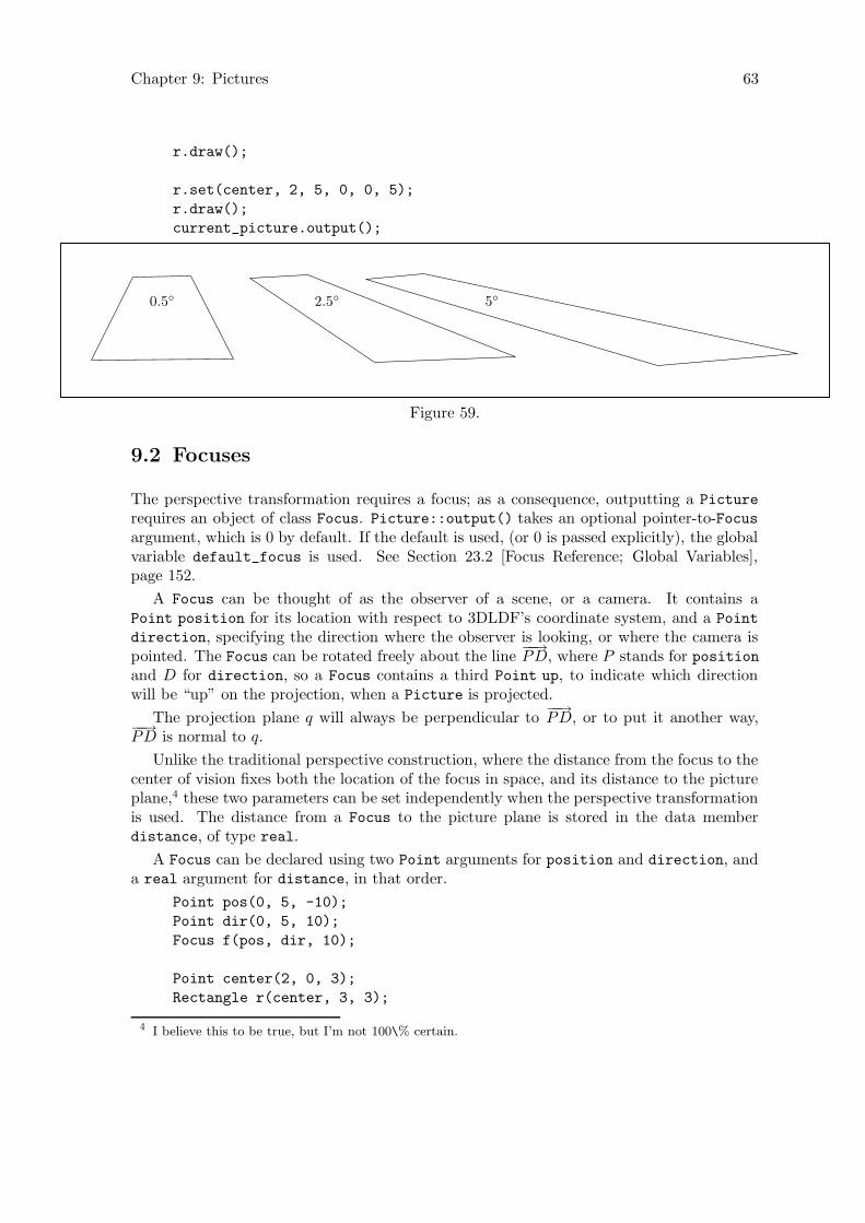
Chapter 9: Pictures 63
r.draw();
r.set(center, 2, 5, 0, 0, 5);
r.draw();
current_picture.output();
0.5◦ 2.5◦ 5◦
Figure 59.
9.2 Focuses
The perspective transformation requires a focus; as a consequence, outputting a Picture
requires an object of class Focus. Picture::output() takes an optional pointer-to-Focusargument, which is 0 by default. If the default is used, (or 0 is passed explicitly), the globalvariable default_focus is used. See Section 23.2 [Focus Reference; Global Variables],page 152.
A Focus can be thought of as the observer of a scene, or a camera. It contains aPoint position for its location with respect to 3DLDF’s coordinate system, and a Point
direction, specifying the direction where the observer is looking, or where the camera ispointed. The Focus can be rotated freely about the line
−−→PD, where P stands for position
and D for direction, so a Focus contains a third Point up, to indicate which directionwill be “up” on the projection, when a Picture is projected.
The projection plane q will always be perpendicular to−−→PD, or to put it another way,
−−→PD is normal to q.
Unlike the traditional perspective construction, where the distance from the focus to thecenter of vision fixes both the location of the focus in space, and its distance to the pictureplane,4 these two parameters can be set independently when the perspective transformationis used. The distance from a Focus to the picture plane is stored in the data memberdistance, of type real.
A Focus can be declared using two Point arguments for position and direction, anda real argument for distance, in that order.
Point pos(0, 5, -10);
Point dir(0, 5, 10);
Focus f(pos, dir, 10);
Point center(2, 0, 3);
Rectangle r(center, 3, 3);
4 I believe this to be true, but I’m not 100\% certain.
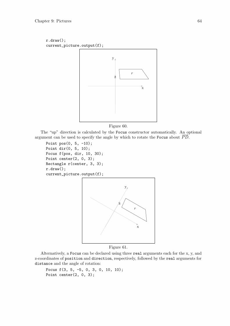
Chapter 9: Pictures 64
r.draw();
current_picture.output(f);
r
x
y
z
Figure 60.
The “up” direction is calculated by the Focus constructor automatically. An optionalargument can be used to specify the angle by which to rotate the Focus about
−−→PD.
Point pos(0, 5, -10);
Point dir(0, 5, 10);
Focus f(pos, dir, 10, 30);
Point center(2, 0, 3);
Rectangle r(center, 3, 3);
r.draw();
current_picture.output(f);
r
x
y
z
Figure 61.
Alternatively, a Focus can be declared using three real arguments each for the x, y, andz-coordinates of position and direction, respectively, followed by the real arguments fordistance and the angle of rotation:
Focus f(3, 5, -5, 0, 3, 0, 10, 10);
Point center(2, 0, 3);
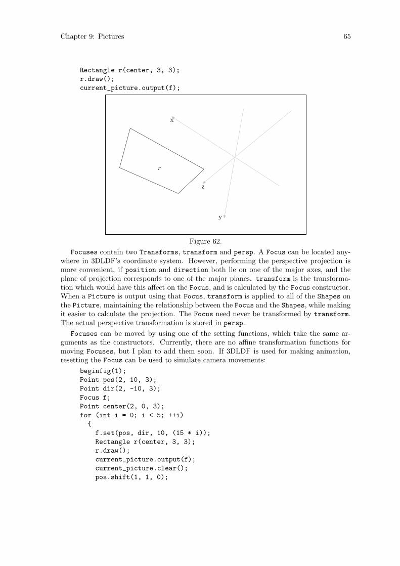
Chapter 9: Pictures 65
Rectangle r(center, 3, 3);
r.draw();
current_picture.output(f);
r
x
y
z
Figure 62.
Focuses contain two Transforms, transform and persp. A Focus can be located any-where in 3DLDF’s coordinate system. However, performing the perspective projection ismore convenient, if position and direction both lie on one of the major axes, and theplane of projection corresponds to one of the major planes. transform is the transforma-tion which would have this affect on the Focus, and is calculated by the Focus constructor.When a Picture is output using that Focus, transform is applied to all of the Shapes onthe Picture, maintaining the relationship between the Focus and the Shapes, while makingit easier to calculate the projection. The Focus need never be transformed by transform.The actual perspective transformation is stored in persp.
Focuses can be moved by using one of the setting functions, which take the same ar-guments as the constructors. Currently, there are no affine transformation functions formoving Focuses, but I plan to add them soon. If 3DLDF is used for making animation,resetting the Focus can be used to simulate camera movements:
beginfig(1);
Point pos(2, 10, 3);
Point dir(2, -10, 3);
Focus f;
Point center(2, 0, 3);
for (int i = 0; i < 5; ++i)
{
f.set(pos, dir, 10, (15 * i));
Rectangle r(center, 3, 3);
r.draw();
current_picture.output(f);
current_picture.clear();
pos.shift(1, 1, 0);
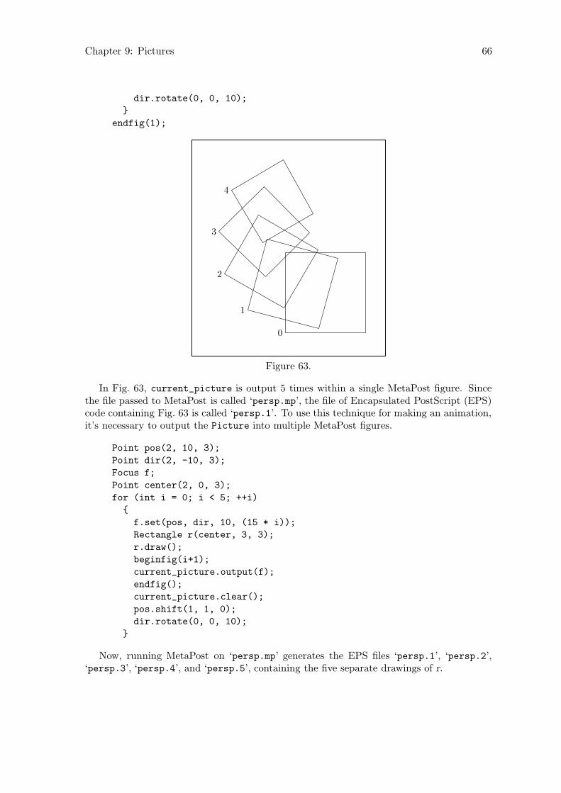
Chapter 9: Pictures 66
dir.rotate(0, 0, 10);
}
endfig(1);
0
1
2
3
4
Figure 63.
In Fig. 63, current_picture is output 5 times within a single MetaPost figure. Sincethe file passed to MetaPost is called ‘persp.mp’, the file of Encapsulated PostScript (EPS)code containing Fig. 63 is called ‘persp.1’. To use this technique for making an animation,it’s necessary to output the Picture into multiple MetaPost figures.
Point pos(2, 10, 3);
Point dir(2, -10, 3);
Focus f;
Point center(2, 0, 3);
for (int i = 0; i < 5; ++i)
{
f.set(pos, dir, 10, (15 * i));
Rectangle r(center, 3, 3);
r.draw();
beginfig(i+1);
current_picture.output(f);
endfig();
current_picture.clear();
pos.shift(1, 1, 0);
dir.rotate(0, 0, 10);
}
Now, running MetaPost on ‘persp.mp’ generates the EPS files ‘persp.1’, ‘persp.2’,‘persp.3’, ‘persp.4’, and ‘persp.5’, containing the five separate drawings of r.

Chapter 9: Pictures 67
9.3 Surface Hiding
In Fig. 64, Circle c lies in front of Rectangle r. Since c is drawn and not filled, r is visiblebehind c.
default_focus.set(1, 3, -5, 0, 3, 5, 10);
Point p(0, -2, 5);
Rectangle r(p, 3, 4, 90);
r.draw();
Point q(2, -2, 3);
Circle c(q, 3, 90);
c.draw();
current_picture.output();
r
c
Figure 64.
If instead, c is filled or filldrawn, only the parts of r that are not covered by c should bevisible:
r.draw();
c.filldraw();
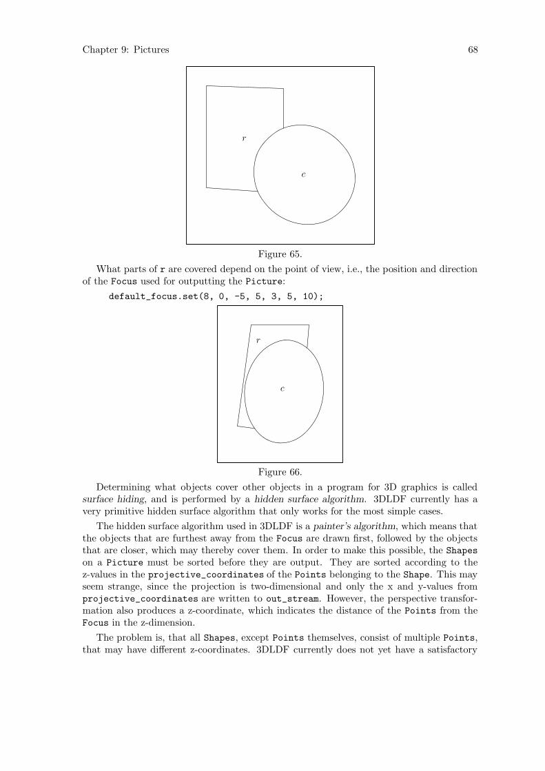
Chapter 9: Pictures 68
r
c
Figure 65.
What parts of r are covered depend on the point of view, i.e., the position and directionof the Focus used for outputting the Picture:
default_focus.set(8, 0, -5, 5, 3, 5, 10);
r
c
Figure 66.
Determining what objects cover other objects in a program for 3D graphics is calledsurface hiding, and is performed by a hidden surface algorithm. 3DLDF currently has avery primitive hidden surface algorithm that only works for the most simple cases.
The hidden surface algorithm used in 3DLDF is a painter’s algorithm, which means thatthe objects that are furthest away from the Focus are drawn first, followed by the objectsthat are closer, which may thereby cover them. In order to make this possible, the Shapes
on a Picture must be sorted before they are output. They are sorted according to thez-values in the projective_coordinates of the Points belonging to the Shape. This mayseem strange, since the projection is two-dimensional and only the x and y-values fromprojective_coordinates are written to out_stream. However, the perspective transfor-mation also produces a z-coordinate, which indicates the distance of the Points from theFocus in the z-dimension.
The problem is, that all Shapes, except Points themselves, consist of multiple Points,that may have different z-coordinates. 3DLDF currently does not yet have a satisfactory
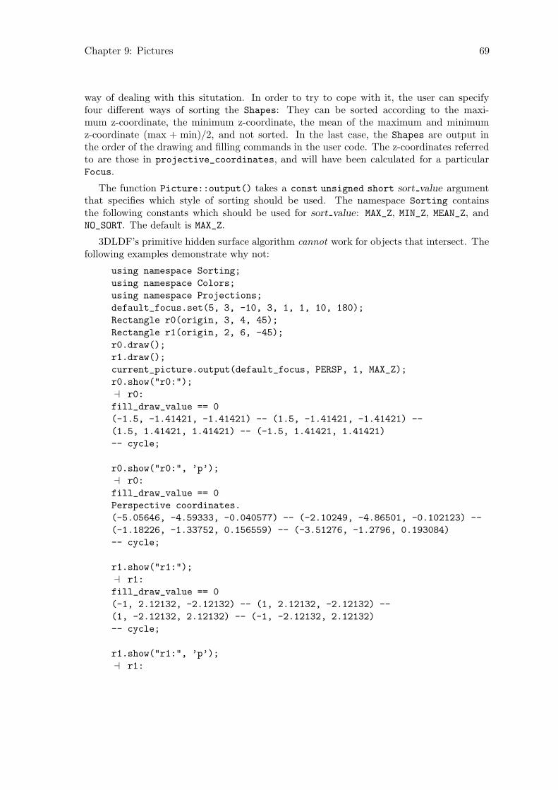
Chapter 9: Pictures 69
way of dealing with this situtation. In order to try to cope with it, the user can specifyfour different ways of sorting the Shapes: They can be sorted according to the maxi-mum z-coordinate, the minimum z-coordinate, the mean of the maximum and minimumz-coordinate (max + min)/2, and not sorted. In the last case, the Shapes are output inthe order of the drawing and filling commands in the user code. The z-coordinates referredto are those in projective_coordinates, and will have been calculated for a particularFocus.
The function Picture::output() takes a const unsigned short sort value argumentthat specifies which style of sorting should be used. The namespace Sorting containsthe following constants which should be used for sort value: MAX_Z, MIN_Z, MEAN_Z, andNO_SORT. The default is MAX_Z.
3DLDF’s primitive hidden surface algorithm cannot work for objects that intersect. Thefollowing examples demonstrate why not:
using namespace Sorting;
using namespace Colors;
using namespace Projections;
default_focus.set(5, 3, -10, 3, 1, 1, 10, 180);
Rectangle r0(origin, 3, 4, 45);
Rectangle r1(origin, 2, 6, -45);
r0.draw();
r1.draw();
current_picture.output(default_focus, PERSP, 1, MAX_Z);
r0.show("r0:");
a r0:
fill_draw_value == 0
(-1.5, -1.41421, -1.41421) -- (1.5, -1.41421, -1.41421) --
(1.5, 1.41421, 1.41421) -- (-1.5, 1.41421, 1.41421)
-- cycle;
r0.show("r0:", ’p’);
a r0:
fill_draw_value == 0
Perspective coordinates.
(-5.05646, -4.59333, -0.040577) -- (-2.10249, -4.86501, -0.102123) --
(-1.18226, -1.33752, 0.156559) -- (-3.51276, -1.2796, 0.193084)
-- cycle;
r1.show("r1:");
a r1:
fill_draw_value == 0
(-1, 2.12132, -2.12132) -- (1, 2.12132, -2.12132) --
(1, -2.12132, 2.12132) -- (-1, -2.12132, 2.12132)
-- cycle;
r1.show("r1:", ’p’);
a r1:
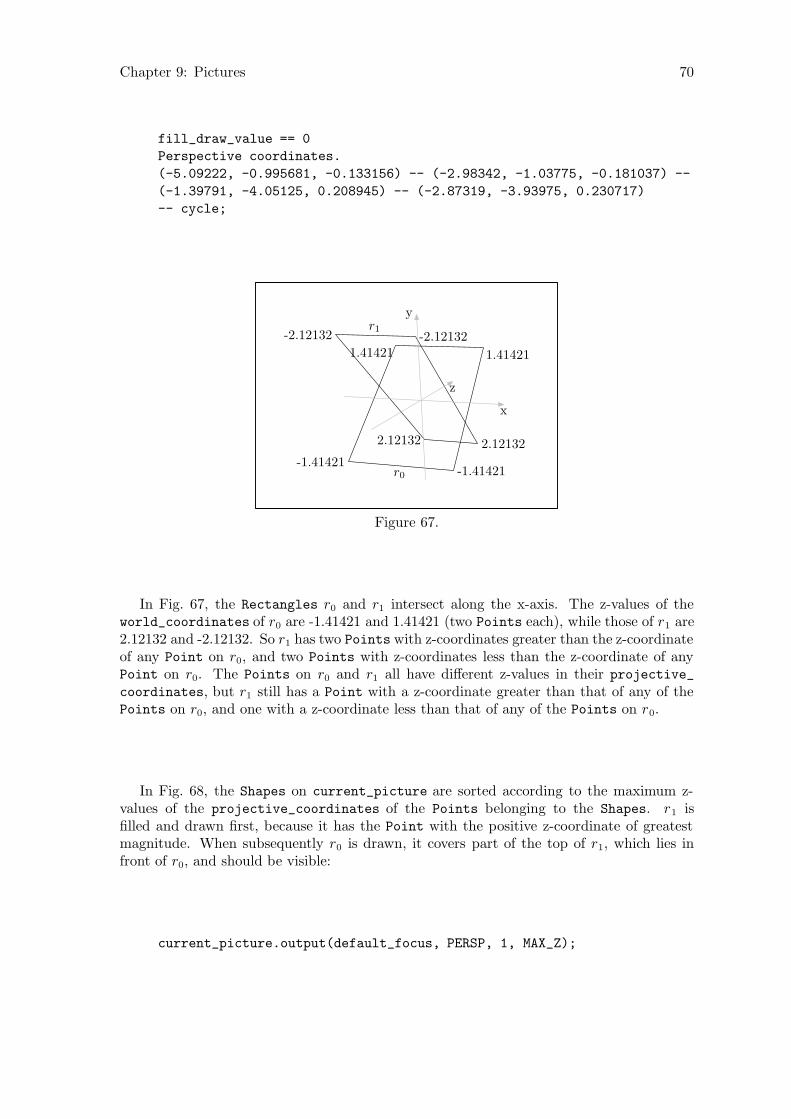
Chapter 9: Pictures 70
fill_draw_value == 0
Perspective coordinates.
(-5.09222, -0.995681, -0.133156) -- (-2.98342, -1.03775, -0.181037) --
(-1.39791, -4.05125, 0.208945) -- (-2.87319, -3.93975, 0.230717)
-- cycle;
-1.41421-1.41421
1.414211.41421
-2.12132 -2.12132
2.121322.12132
r0
r1
x
y
z
Figure 67.
In Fig. 67, the Rectangles r0 and r1 intersect along the x-axis. The z-values of theworld_coordinates of r0 are -1.41421 and 1.41421 (two Points each), while those of r1 are2.12132 and -2.12132. So r1 has two Points with z-coordinates greater than the z-coordinateof any Point on r0, and two Points with z-coordinates less than the z-coordinate of anyPoint on r0. The Points on r0 and r1 all have different z-values in their projective_
coordinates, but r1 still has a Point with a z-coordinate greater than that of any of thePoints on r0, and one with a z-coordinate less than that of any of the Points on r0.
In Fig. 68, the Shapes on current_picture are sorted according to the maximum z-values of the projective_coordinates of the Points belonging to the Shapes. r1 isfilled and drawn first, because it has the Point with the positive z-coordinate of greatestmagnitude. When subsequently r0 is drawn, it covers part of the top of r1, which lies infront of r0, and should be visible:
current_picture.output(default_focus, PERSP, 1, MAX_Z);
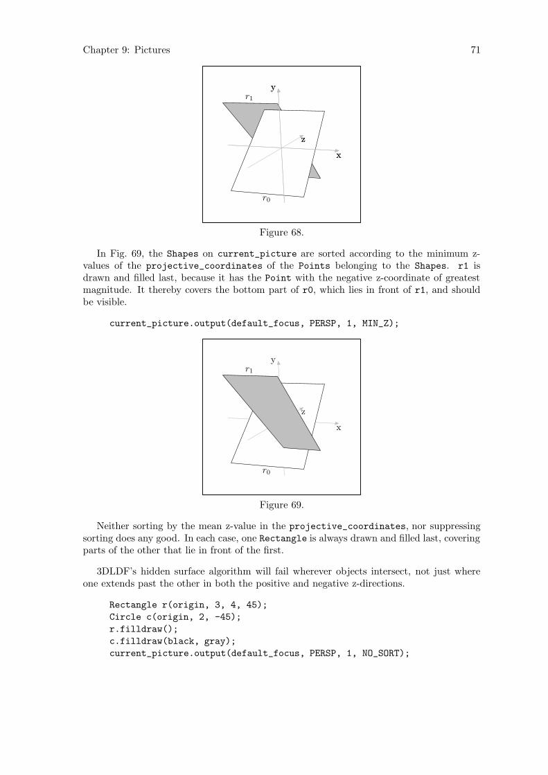
Chapter 9: Pictures 71
r0
r1
x
y
z
x
y
z
Figure 68.
In Fig. 69, the Shapes on current_picture are sorted according to the minimum z-values of the projective_coordinates of the Points belonging to the Shapes. r1 isdrawn and filled last, because it has the Point with the negative z-coordinate of greatestmagnitude. It thereby covers the bottom part of r0, which lies in front of r1, and shouldbe visible.
current_picture.output(default_focus, PERSP, 1, MIN_Z);
r0
r1
x
y
z
Figure 69.
Neither sorting by the mean z-value in the projective_coordinates, nor suppressingsorting does any good. In each case, one Rectangle is always drawn and filled last, coveringparts of the other that lie in front of the first.
3DLDF’s hidden surface algorithm will fail wherever objects intersect, not just whereone extends past the other in both the positive and negative z-directions.
Rectangle r(origin, 3, 4, 45);
Circle c(origin, 2, -45);
r.filldraw();
c.filldraw(black, gray);
current_picture.output(default_focus, PERSP, 1, NO_SORT);
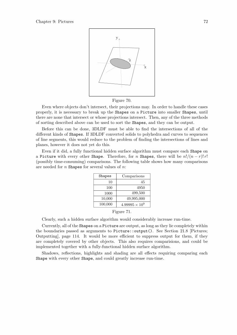
Chapter 9: Pictures 72
x
y
z
Figure 70.
Even where objects don’t intersect, their projections may. In order to handle these casesproperly, it is necessary to break up the Shapes on a Picture into smaller Shapes, untilthere are none that intersect or whose projections intersect. Then, any of the three methodsof sorting described above can be used to sort the Shapes, and they can be output.
Before this can be done, 3DLDF must be able to find the intersections of all of thedifferent kinds of Shapes. If 3DLDF converted solids to polyhedra and curves to sequencesof line segments, this would reduce to the problem of finding the intersections of lines andplanes, however it does not yet do this.
Even if it did, a fully functional hidden surface algorithm must compare each Shape ona Picture with every other Shape. Therefore, for n Shapes, there will be n!/(n− r)! r!(possibly time-consuming) comparisons. The following table shows how many comparisonsare needed for n Shapes for several values of n:
Shapes Comparisons
10 45
100 4950
1000 499,500
10,000 49,995,000
100,000 4.99995× 10⁹
Figure 71.
Clearly, such a hidden surface algorithm would considerably increase run-time.
Currently, all of the Shapes on a Picture are output, as long as they lie completely withinthe boundaries passed as arguments to Picture::output(). See Section 21.8 [Pictures;Outputting], page 114. It would be more efficient to suppress output for them, if theyare completely covered by other objects. This also requires comparisions, and could beimplemented together with a fully-functional hidden surface algorithm.
Shadows, reflections, highlights and shading are all effects requiring comparing eachShape with every other Shape, and could greatly increase run-time.

Chapter 10: Intersections 73
10 Intersections
There are no functions for finding the intersection points of two (or more) arbitrary Paths.This is impossible, so long as 3DLDF outputs MetaPost code. 3DLDF only “knows” aboutthe Points on a Path; it doesn’t actually generate the curve or other figure that passesthrough the Points, and consequently doesn’t “know” how it does this.
In addition, an arbitrary Path can contain connectors. In 3DLDF, the connectors aremerely strings and are written verbatim to the output file, however, in MetaPost theyinfluence the form of a Path.
3DLDF can, however, find the intersection points of some non-arbitrary Paths. So far,it can find the intersection point of the following combinations of Paths:
1. Two linear Paths, i.e., Paths for which Path::is_linear() returns true (see Sec-tion 26.15 [Path Reference; Querying], page 194). In addition, the static Point
member function Point::intersection_points() can be called with four Point ar-guments. The first and second arguments are treated as the end points of one line, andthe third and fourth arguments as the end points of the other.
2. A line and a Polygon. Currently, Reg_Polygon and Rectangle are the only classesderived from Polygon.
3. Two Polygons.
4. A line and a Regular Closed Plane Curve (Reg_Cl_Plane_Curve, see Section 30.3[Regular Closed Plane Curve Reference; Intersections], page 217). Currently, Ellipseand Circle are the only classes derived from Reg_Cl_Plane_Curve.
5. Two Ellipses. Since a Circle is also an Ellipse, one or both of the Ellipses maybe a Circle. See Section 31.9 [Ellipse Reference; Intersections], page 230.
Adding more functions for finding the intersections of various geometric figures is one ofmy main priorities with respect to extending 3DLDF.
There are currently no special functions for finding the intersection points of a lineand a Circle or two Circles. Since the class Circle is derived from class Ellipse,Circle::intersection_points() resolves to Ellipse::intersection_points(), which,in turn, calls Reg_Cl_Plane_Curve::intersection_points(). This does the trick, butit’s much easier to find the intersections for Circles that it is for Ellipses. In particular,the intersections of two coplanar Circles can be found algebraically, whereas I’ve had toimplement a numerical solution for the case of two coplanar Ellipses with different centersand/or axis orientation. It may also be worthwhile to write a specialization for finding theintersection points of a Circle and an Ellipse.
The theory of intersections is a fascinating and non-trivial branch of mathematics.1 AsI learn more about it, I plan to define more classes to represent various curves (two-dimensional ones to start with) and functions for finding their intersection points.
1 The books on computer graphics and the fairly elementary mathematics books that I own or have referredto don’t go into intersections very deeply. One that does is Fischer, Gerd. Ebene Algebraische Kurven,which is a bit over my head.

Chapter 11: Installing and Running 3DLDF 74
11 Installing and Running 3DLDF
11.1 Installing 3DLDF
3DLDF is available for downloading from http://ftp.gnu.org/gnu/3dldf. Theofficial 3DLDF website is http://www.gnu.org/software/3dldf. The “tarball”, i.e.,the compressed archive file ‘3DLDF-1.1.5.1.tar.gz’ unpacks into a directory called‘/3DLDF-1.1.5.1/’.
On a typical Unix-like system, entering the following commands at the command linein a shell will unpack the 3DLDF distribution. Please note that the form of the commandsmay differ on your system.
gunzip 3DLDF-1.1.5.1.tar.gz
tar xpvf 3DLDF-1.1.5.1.tar
The ‘p’ option to tar ensures that the files will have the same permissions as when theywere packed.
The directory ‘3DLDF-1.1.5.1/’ contains a configure script, which should be calledfrom the command line in the shell, using the absolute path of ‘3DLDF-1.1.5.1/’ as the pre-fix argument. For example, if the path is ‘/usr/local/mydir/3DLDF-1.1.5.1/’, configureshould be invoked as follows:
cd 3DLDF-1.1.5.1
configure --prefix=/usr/local/mydir/3DLDF-1.1.5.1/
configure generates a ‘Makefile’ from the ‘Makefile.in’ in ‘3DLDF-1.1.5.1/’,and in each of the subdirectories ‘3DLDF-1.1.5.1/CWEB’, ‘3DLDF-1.1.5.1/DOC’, and‘3DLDF-1.1.5.1/DOC/TEXINFO’. Now, make install causes the 3DLDF to be built. Theexecutable is called ‘3dldf’.
See the files ‘README’ and ‘INSTALL’ in the 3DLDF distribution for more information.
11.1.1 Template Functions
3DLDF 1.1.5 is the first release that contains template functions, namely template <class
C> C* create_new(), which is defined in ‘creatnew.web’, and template <class Real>
Real get_second_largest(), which is defined in gsltmplt.web. See Chapter 14 [DynamicAllocation of Shapes], page 84, and Section 15.3 [Get Second Largest Real], page 87.
In order for template functions to be instantiated correctly, their definitions must beavailable in each compilation unit where specializations are declared or used. For non-template functions, it suffices for their declarations to be available, and their definitionsare found at link-time. For this reason, the definitions of create_new() and get_second_
largest() are in their own CWEB files, and are written to their own header files. Thelatter are included in the other CWEB files that need them.
In addition, ‘AM_CXXFLAGS = -frepo’ has been added to the file ‘Makefile.am’ in‘3DLDF-1.1.5/CWEB/’, so that the C++ compiler is called using the ‘-frepo’ option. Themanual Using and Porting the GNU Compiler Collection explains this as follows:
Chapter 11: Installing and Running 3DLDF 75
“Compile your template-using code with ‘-frepo’. The compiler will generatefiles with the extension ‘.rpo’ listing all of the template instantiations usedin the corresponding object files which could be instantiated there; the linkwrapper, ‘collect2’, will then update the ‘.rpo’ files to tell the compiler whereto place those instantiations and rebuild any affected object files. The link-timeoverhead is negligible after the first pass, as the compiler will continue to placethe instantiations in the same files.”1
The first time the executable ‘3dldf’ is built, the files that use the template functionsare recompiled one or more times, and the linker is also called several times. This doesn’thappen anymore, once the ‘.rpo’ files exist.
Template instantiation differs from compiler to compiler, so using template functionswill tend to make 3DLDF less portable. I am no longer able to compile it on the DECalphaPersonal Workstation I had been using with the DEC C++ compiler. See Section 1.6 [Ports],page 8, for more information.
11.2 Running 3DLDF
To use 3DLDF, call make run from the command line in the shell. The working directoryshould be ‘3DLDF-1.1.5.1/’ or ‘3DLDF-1.1.5.1/CWEB’. Either will work, but the lattermay be more convenient, because this is the location of the CWEB, TEX and MetaPostfiles that you’ll be editing. Alternatively, call ldfr, which is merely a shell script thatcalls make run. This takes care of running 3dldf, MetaPost, TEX, and dvips, producing aPostScript file containing your drawings. You can display the latter on your terminal usingGhostview or some other PostScript viewer, print it out, and whatever else you like to dowith PostScript files.
However, you can also perform the actions performed by make run by hand, by writingyour own shell scripts, by defining Emacs-Lisp commands, or in other ways. Even if youchoose to use make run, it’s important to understand what it does. The following explainshow to do this by hand.
The CWEB source files for 3DLDF are in the subdirectory ‘3DLDF-1.1.5.1/CWEB/’.They must be ctangled, and the resulting C++ files must be compiled and linked, inorder to create the executable file ‘3dldf’. The C++ files and header files generated byctangle, the object files generated by the compiler, and the executable ‘3dldf’ all residein ‘3DLDF-1.1.5.1/CWEB/’. Therefore, the latter must be your working directory.
Since 3DLDF has no input routine as yet, as explained in Section 1.5.2 [No Input Rou-tine], page 8, it is necessary to add C++ code to the function main() in ‘main.web’, and/orin a separate function in another file. In the latter case, the function containing the usercode must be invoked in main(). Look for the line “Your code here!” in ‘main.web’.
This is an example of what you could write in main(). Feel free to make it morecomplicated, if you wish.
beginfig(1);
default_focus.set(2, 3, -10, 2, 3, 10, 20);
Rectangle R(origin, 5, 3);
1 Stallman, Richard M. Using and Porting the GNU Compiler Collection, p. 285.
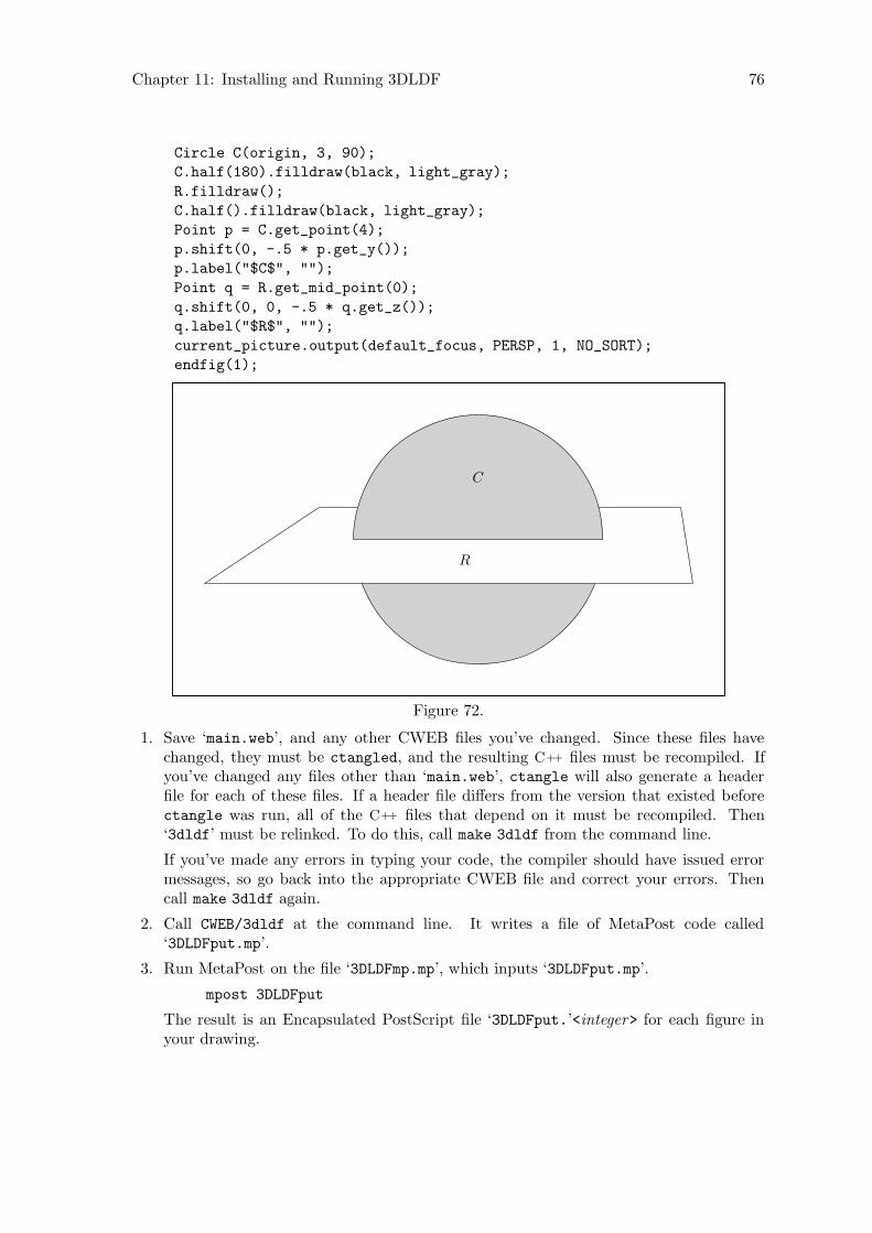
Chapter 11: Installing and Running 3DLDF 76
Circle C(origin, 3, 90);
C.half(180).filldraw(black, light_gray);
R.filldraw();
C.half().filldraw(black, light_gray);
Point p = C.get_point(4);
p.shift(0, -.5 * p.get_y());
p.label("$C$", "");
Point q = R.get_mid_point(0);
q.shift(0, 0, -.5 * q.get_z());
q.label("$R$", "");
current_picture.output(default_focus, PERSP, 1, NO_SORT);
endfig(1);
C
R
Figure 72.
1. Save ‘main.web’, and any other CWEB files you’ve changed. Since these files havechanged, they must be ctangled, and the resulting C++ files must be recompiled. Ifyou’ve changed any files other than ‘main.web’, ctangle will also generate a headerfile for each of these files. If a header file differs from the version that existed beforectangle was run, all of the C++ files that depend on it must be recompiled. Then‘3dldf’ must be relinked. To do this, call make 3dldf from the command line.
If you’ve made any errors in typing your code, the compiler should have issued errormessages, so go back into the appropriate CWEB file and correct your errors. Thencall make 3dldf again.
2. Call CWEB/3dldf at the command line. It writes a file of MetaPost code called‘3DLDFput.mp’.
3. Run MetaPost on the file ‘3DLDFmp.mp’, which inputs ‘3DLDFput.mp’.
mpost 3DLDFput
The result is an Encapsulated PostScript file ‘3DLDFput.’<integer> for each figure inyour drawing.
Chapter 11: Installing and Running 3DLDF 77
4. The file ‘3DLDFtex.tex’ should contain code for including the ‘3DLDFput.’<integer>
files. This is an example taken from the ‘3DLDFtex.tex’ included in the distribution.You may change it to suit your purposes.
\vbox to \vsize{\vskip 2cm
\line{\hskip 2cm Figure 1.\hss}%
\vfil
\line{\hskip 2cm\epsffile{3DLDFmp.1}\hss}%
\vss}
5. Run TEX on ‘3DLDFtex.tex’ to produce the DVI file, ‘3DLDFtex.dvi’.
tex 3DLDFtex
6. Run dvips on the DVI file to produce the PostScript file, ‘3DLDFtex.ps’.
dvips -o 3DLDFtex.ps 3DLDFtex
7. ‘3DLDFtex.ps’ can be viewed using Ghostview, it can be printed using lpr (on a Unix-like system), you can convert it to PDF with ps2pdf, or to some other format usingthe appropriate program.
I sincerely hope that it worked. If it didn’t, ask your local computer wizard for help.
On the computer I’m using, I found that special arguments for setting landscape andpapersize in TEX files for DIN A3 landscape didn’t work. Ghostview cut off the right sidesof the drawings. Nor did it work to call dvips -t landscape -t a3. This caused an errormessage which said that landscape would be ignored. When I called dvips with the ‘-tlandscape’ option alone, it worked, and Ghostview showed the entire drawing.
Another problem was Adobe Acrobat. It would display the entire DIN A3 page, but notalways in landscape format. I was unable to find a way of rotating the pages in Acrobat.I finally found out, that if I included even a single letter of text in a label, Acrobat woulddisplay the document correctly.
11.2.1 Converting EPS Files
ImageMagick (http://www.imagemagick.org) is a “collection of tools and libraries” forimage manipulation. It provides a ‘convert’ utility which can convert images from one for-mat to another. It can convert structured PostScript (PS) to to Portable Network Graph-ics (PNG) (http://www.libpng.org/pub/png/index.html), but not EPS (EncapsulatedPostScript) to PNG. Nor can it convert EPS to structured PostScript.
It is possible to have MetaPost generate structured PostScript directly by includingthe command ‘prologues:=1;’ at the beginning of the MetaPost input. However, this“generally doesn’t work when you use TEX fonts.”2 This is a significant problem if yourlabels contain math mode material, and you haven’t already taken steps to ensure thatappropriate fonts will be used in the PS output.
In the following, I describe the only way I’ve found to convert an EPS image to PNGformat while still using TEX fonts. There may be other and better ways of doing this, butI haven’t found them.
2 Hobby, A User’s Manual for MetaPost, pp. 21–22.
Chapter 11: Installing and Running 3DLDF 78
1. Assume the EPS image is in the file ‘3DLDFmp.1’ Include the EPS image in a TEX filewhich looks like this:
\advance\voffset by -1in
\advance\hoffset by -1in
\nopagenumbers
\input epsf
\epsfverbosetrue
\def\epsfsize#1#2{#1}
\setbox0=\vbox{\epsffile{3DLDFmp.1}}
\vsize=\ht0
\hsize=\wd0
\special{papersize=\the\wd0,\the\ht0}
\box0
\bye
Do not name this file ‘3DLDFmp.1.tex’! While this worked fine for me on a DECalphaPersonal Workstation running under Tru64 Unix 5.1, with TEX, Version 3.1415 (Cversion 6.1), and dvipsk 5.58f, it failed on a PC Pentium II XEON under Linux 2.4,with TEX, Version 3.14159 (Web2C 7.4.5), and dvips(k) 5.92b, kpathsea version 3.4.5,with the following error message:
“No BoundingBox comment found in file examples.1; using defaults”
The resulting PS image had the wrong size and the the graphic was positioned improp-erly.
Apparently, it confuses the EPSF macros when the name of an included image is thesame as ‘\jobname’. So, for this example, let’s call it ‘3DLDFmp.1_.tex’.
You don’t really need to call the macro ‘\epsfverbosetrue’. If you do, it will printthe measurements of the bounding box and other information to standard output.3
2. Run ‘tex 3DLDFmp.1_.tex’.
3. Run ‘dvips -o 3DLDF.1.ps 3DLDFmp.1_.dvi’.
4. Run ‘convert 3DLDF.1.ps 3DLDFmp.1.png’.
ImageMagick supplies a ‘display’ utility, which can be used to display the PNG image:
display 3DLDFmp.1.png
It can be included in an HTML document as follows:
<img src="3DLDFmp.1.png"
alt="[Fig. 1]."
Please note! The PNG files for this manual are now called filename ‘3DLDF1.png’,‘3DLDF2.png’, . . . , ‘3DLDF199.png’, because I wasn’t able to write files with names like‘3DLDFmp.<number>.png’ to a CD-R (Compact Disk, Recordable), when ‘number ’ had morethan one digit.
3 Rokicki, Dvips: A DVI-to-PostScript Translator, p. 24.
Chapter 11: Installing and Running 3DLDF 79
11.2.1.1 Emacs-Lisp Functions
The file ‘3DLDF-1.1.5.1/CWEB/cnepspng.el’ contains definitions of two Emacs-Lispfunctions that can be used to convert Encapsulated PostScript (EPS) files to structuredPostScript (PS) and Portable Network Graphics (PNG) files.
[Emacs-Lisp function]convert-eps filename do-not-delete-files
Converts an EPS image file to the PS and PNG formats.
If called interactively, convert-eps prompts for the filename, including the extension,of an EPS image file. It follows the procedure described above in Section 11.2.1[Converting EPS Files], page 77, to create ‘filename.ps’ and ‘filename.png’.
If do-not-delete-files is nil, the ‘.tex’, ‘.dvi’, and ‘.log’ files will be deleted. Thisis the case when convert-eps is called interactively with no prefix argument. Ifconvert-eps is called interactively with a prefix argument, or non-interactively witha non-nil do-not-delete-files argument, these files will not be deleted.
[Emacs-Lisp function]convert-eps-loop arg start end
Converts a set of EPS image files to the PS and PNG formats. The files must all havethe same filename, and the extensions must form a range of positive integers. For ex-ample, convert-eps-loop can be used to convert the files ‘3DLDFmp.1’, ‘3DLDFmp.2’,and ‘3DLDFmp.3’ to ‘3DLDFmp.1.ps’, ‘3DLDFmp.2.ps’, and ‘3DLDFmp.3.ps’ on the onehand, and ‘3DLDFmp.1.png’, ‘3DLDFmp.2.png’, ‘3DLDFmp.3.png’ on the other.
If convert-eps-loop is called interactively, it prompts for filename with no extension
and the starting and ending numbers of the range.
For all i ∈ Z and start ≤ i ≤ end, convert-eps-loop checks whether a file named‘filename.i’ exists. If it does, it calls convert-eps, passing ‘filename.i’ as thelatter’s filename argument.
do-not-delete-files is also passed to convert-eps. If it’s nil, the ‘.tex’, ‘.dvi’, and‘.log’ files will be deleted. This is the case when convert-eps-loop is called inter-actively with no prefix argument. If convert-eps-loop is called interactively witha prefix argument, or non-interactively with a non-nil do-not-delete-files argument,these files will not be deleted.
11.2.2 Command Line Arguments
3dldf can be called with the following command line arguments.
--help Prints information about the valid command line options to standard outputand exits with return value 0.
--silent Suppresses some output to standard output and standard error when 3dldf isrun
--verbose
Causes status information to be printed to standard output when 3dldf is run.
--version
Prints the version number of 3DLDF to standard output and exits with returnvalue 0.

Chapter 11: Installing and Running 3DLDF 80
Currently, 3dldf can only handle long options. ‘-’ cannot be substituted for ‘--’. How-ever, the names of the options themselves can be abbreviated, as long as the abbreviationis unambigous. For example, ‘3dldf --h’ and ‘3dldf --verb’ are valid, but ‘3dldf --ver’is not.

Chapter 12: Typedefs and Utility Structures 81
12 Typedefs and Utility Structures
3DLDF defines a number of data types for various reasons, e.g., for the sake of convenience,for use in conditional compilation, or as return values of functions. Some of these datatypes can be defined using typedef, while others are defined as structs.
The typedefs and utility structures described in this chapter are found in ‘pspglb.web’.Others, that contain objects of types defined in 3DLDF, are described in subsequent chap-ters.
[typedef]realSynonymous either with float or double, depending on the values of the prepro-cessor variables LDF_REAL_FLOAT and LDF_REAL_DOUBLE. The meaning of real isdetermined by means of conditional compilation. If real is float, 3DLDF will re-quire less memory than if real is double, but its calculations will be less precise.real is “typedeffed” to float by default.
[typedef]real pair first secondSynonymous with pair<real, real>.
[struct]real triple first second thirdAll three data elements of real_triple are reals. It also has two constructors,described below. There are no other member functions.
[Constructor]void real triple (void)[Constructor]void real triple (real a, real b, real c )
The constructor taking no arguments sets first, second, and third to 0. Theconstructor taking three real arguments sets first to a, second to b, and third toc.
[typedef]MatrixA Matrix is a 4 × 4 array of real, e.g., Matrix M; ≡ real M[4][4]. It is used inclass Transform for storing transformation matrices. See Chapter 4 [Transforms],page 19, and See Chapter 19 [Transform Reference], page 96, for more information.
[typedef]real short first secondSynonymous with pair<real, signed short>. It is the return type of Plane::get_distance().
[typedef]bool pair first secondSynonymous with pair<bool, bool>.
[typedef]bool real first secondSynonymous with pair<bool, real>.
Chapter 13: Global Constants and Variables 82
13 Global Constants and Variables
The global constants and variables described in this chapter are found in ‘pspglb.web’.Others, of types defined in 3DLDF, are described in subsequent chapters.
[Constants]bool ldf real floatbool ldf real double
Set to 0 or 1 to match the values of the preprocessor macros LDF_REAL_FLOAT andLDF_REAL_DOUBLE. The latter are used for conditional compilation and determinewhether real is “typedeffed” to float or double, i.e., whether real is made to be asynonym of float or double using typedef.
ldf_real_float and ldf_real_double can be used to control conditional expressionsin non-conditionally compiled code.
[Constant]real PIThe value of PI (π) is calculated as 4.0 × arctan(1.0). I believe that a preprocessormacro “PI” was available when I compiled 3DLDF using the DEC C++ compiler, andthat it wasn’t, when I used GNU CC under Linux, but I’m no longer sure.
[Variable]valarray <real> null coordinatesContains four elements, all 0. Used for resetting the sets of coordinates belonging toPoints, but only when the DEC C++ compiler is used. This doesn’t work when GCCis used.
[Constant]real INVALID REALActually, INVALID_REAL is the largest possible real value (i.e., float or double) ona given machine. So, from the point of view of the compiler, it’s not invalid at all.However, 3DLDF uses it to indicate failure of some kind. For example, the returnvalue of a function returning real can be compared with INVALID_REAL to checkwhether the function succeeded or failed.
An alternative approach would be to use the exception handling facilities of C++. Ido use these, but only in a couple of places, so far.
[Constant]real_pair INVALID REAL PAIRfirst and second are both INVALID_REAL.
[Constant]real INVALID REAL SHORTfirst is INVALID_REAL and second is 0.
[Variable]real MAX REALThe largest real value permitted in the the elements of Transforms and the coor-dinates of Points. It is the second largest real value (i.e., float or double) on agiven machine (INVALID_REAL is the largest).
MAX_REAL is a variable, but it should be used like a constant. In other words, usersshould never reset its value. It can’t be declared const because its value must becalculated using function calls, which can’t be done before the entry point of theprogram, i.e., main(). Therefore, the value of MAX_REAL is calculated at the beginningof main().

Chapter 13: Global Constants and Variables 83
[Variable]real MAX REAL SQRTThe square root of MAX_REAL.
MAX_REAL_SQRT is a variable, but it should be used like a constant. In other words,users should never reset its value. It can’t be declared const because its value iscalculated using the sqrt() function, which can’t be done before the entry pointof the program, i.e., main(). Therefore, the value of MAX_REAL_SQRT is set afterMAX_REAL is calculated, at the beginning of main().
MAX_REAL_SQRT is used in Point::magnitude() (see Section 22.15 [VectorOperations], page 136). The magnitude of a Point is found by using the formula√
x2 + y2 + z2. x, y, and z are all tested against MAX_REAL_SQRT to ensure that x2,
y2, and z2 will all be less than or equal to MAX_REAL before trying to calculate them.
Metafont implements an operation called Pythagorean addition, notated as “++”whichcan be used to calculate distances without first squaring and then taking square
roots:1 a++b ≡√
a2 + b2 and a++b++c ≡√
a2 + b2 + c2. This makes it possible
to calculate distances for greater values of a, b, and c, that would otherwise causefloating point errors. Metafont also implements the inverse operation Pythagorean
subtraction, notated as “+-+”: a+−+b ≡√
a2 − b2. Unfortunately, 3DLDF
implements neither Pythagorean addition nor subtraction as yet, but it’s on my listof “things to do”.
1 Knuth, Donald E. The Metafontbook, p. 66.
Chapter 14: Dynamic Allocation of Shapes 84
14 Dynamic Allocation of Shapes
[Template function]template <class C> C* create new (const C* arg )[Template function]template <class C> C* create new (const C& arg )
These functions dynamically allocate an object derived from Shape on the free store,returning a pointer to the type of the Shape and setting on_free_store to true.
If a non-zero pointer or a reference is passed to create_new(), the new object willbe a copy of arg.
It is not possible to instantiate more than one specialization of create_new() thattakes no argument, because calls to these functions would be ambiguous. If the newobject is not meant to be a copy of an existing one, ‘0’ must be passed to create_
new() as its argument.
create_new is called like this:
Point* p = create_new<Point>(0);
p->show("*p:");
a *p: (0, 0, 0)
Color c(.3, .5, .25);
Color* d = create_new<Color>(c);
d->show("*d:");
a*d:
name ==
use_name == 0
red_part == 0.3
green_part == 0.5
blue_part == 0.25
Point a0(3, 2.5, 6);
Point a1(10, 11, 14);
Path q(a0, a1);
Path* r = create_new<Path>(&q);
r->show("*r:");
a*r:
points.size() == 2
connectors.size() == 1
(3, 2.5, 6) -- (10, 11, 14);
Specializations of this template function are currently declared for Color, Point,Path, Reg_Polygon, Rectangle, Ellipse, Circle, Solid, and Cuboid.
Chapter 15: System Information 85
15 System Information
The functions described in this chapter are all declared in the namespace System. Theyare for finding out information about the system on which 3DLDF is being run. Theyare declared and defined in ‘pspglb.web’, except for the template function get_second_
largest(), which is declared and defined in ‘gsltmplt.web’.
There are two reasons for this. The first is that template definitions must be available inthe compilation units where specializations are instantiated. I therefore write the templatedefinition of get_second_largest() to ‘gsltmplt.h’, so it can be included by the CWEBfiles that need it, currently ‘main.web’ only. If I wrote it to ‘pspglb.h’, it would be includedby all of the CWEB files except for ‘loader.web’, causing unnecessarily bloated object code.
The other reason is because of the way way 3DLDF is built using Automake and make. Ioriginally tried to define get_second_largest() in ‘pspglb.web’ and wrote the definitionto ‘gsltmplt.cc’, which is no problem with CWEB. However, I was unable to express thedependencies among the CWEB, C++, and object files in such a way that 3DLDF was builtproperly.
Therefore all template functions will be put into files either by themselves, or in smallgroups.
15.1 Endianness
[Function]signed short get endianness ([const bool verbose = false])Returns the following values:
0 if the processor is little-endian.
1 if the processor is big-endian.
-1 if the endianness cannot be determined.
It is called by is_little_endian() and is_big_endian().
If verbose is true, messages are printed to standard output.
This function has been adapted from Harbison, Samuel P., and Guy L. Steele Jr. C, A
Reference Manual, pp. 163–164. This book has the clearest explanation of endiannessthat I’ve found so far.
This is the C++ code:
signed short
System::get_endianness(const bool verbose)
{
union {
long Long;
char Char[sizeof(long)];
} u;
u.Long = 1;
if (u.Char[0] == 1)
{
if (verbose)
Chapter 15: System Information 86
cout << "Processor is little-endian."
<< endl << endl << flush;
return 0;
}
else if (u.Char[sizeof(long) - 1] == 1)
{
if (verbose)
cout << "Processor is big-endian."
<< endl << endl << flush;
return 1;
}
else
{
cerr << "ERROR! In System::get_endianness():\n"
<< "Can’t determine endianness. Returning -1"
<< endl << endl << flush;
return -1;
}
}
[Function]bool is big endian ([const bool verbose = false])Returns true if the processor is big-endian, otherwise false. If verbose is true,messages are printed to standard output.
[Function]bool is little endian ([const bool verbose = false])Returns true if the processor is little-endian, otherwise false. If verbose is true,messages are printed to standard output.
15.2 Register Width
[Function]unsigned short get register width (void)Returns the register width of the CPU of the system on which 3DLDF is being run.This will normally be either 32 or 64 bits.
This is the C++ code:
return (sizeof(void*) * CHAR_BIT);
This assumes that an address will be the same size as the processor’s registers, andthat CHAR_BIT will be the number of bits in a byte. These are reasonable assumptionsthat apply to all architectures I know about.
This function is called by is_32_bit() and is_64_bit().
[Function]bool is 32 bit (void)Returns true if the CPU of the system on which 3DLDF is being run has a registerwidth of 32 bits, otherwise false.
[Function]bool is 64 bit (void)Returns true if the CPU of the system on which 3DLDF is being run has a registerwidth of 64 bits, otherwise false.

Chapter 15: System Information 87
15.3 Get Second Largest Real
[Template function]template <class Real> Real get second largest (RealMAX_VAL, [bool verbose = false])
[Template specialization]float get second largest (float, bool)[Template specialization]double get second largest (double, bool)
get_second_largest returns the second largest floating point number of the typespecified the template paramater Real. If verbose is true, messages are printed tostandard output.
This function is used for setting the value of MAX_REAL. See Chapter 13 [GlobalConstants and Variables], page 82.
get_second_largest depends on there being an unsigned integer type with the samelength as Real. This should always be the case for float and double, but may notbe long double.
MAX VAL should be the largest number of type Real on a given architecture. TheGNU C++ compiler GCC 3.3 does not currently supply the numeric_limits template,so it is necessary to pass one of the macros FLT_MAX or DBL_MAX explicitly, dependingon which specialization you use1. When and if GCC supplies the numeric_limits
template, I will eliminate the MAX REAL argument.
1 If your system supplies an unsigned integer type with the same length as long double, thenyou can instantiate get_second_largest<long double>() and call ‘get_second_largest<longdouble>(LDBL_MAX)’. However, I doubt that this amount of precision would be worthwhile. If it everwere required, 3DLDF would have to be changed in other ways, too. In particular, it would have to usemore precise trigonometric functions for rotations. See Section 1.5.1 [Accuracy], page 7.
Chapter 16: Color Reference 88
16 Color Reference
Class Color is defined in ‘colors.web’.
16.1 Data Members
[Variable]string nameThe name of the Color.
[Variable]bool use nameIf true, name is written to out_stream when the Color is used for drawing or filling.Otherwise, the RGB (red-green-blue) values are written to out_stream.
[Variable]bool on free storetrue, if the Color has been created by create_new<Color>(), which allocates mem-ory for the Color on the free store. Otherwise false. Colors should only everbe dynamically allocated by using create_new<Color>(). See Section 16.2 [ColorReference;;Constructors and Setting Functions], page 88.
[Variable]real red part[Variable]real green part[Variable]real blue part
The RGB (red-green-blue) values of the Color. A real value r is valid for thesevariables if and only if 0 ≤ r ≤ 1.
16.2 Constructors and Setting Functions
[Default constructor]void Color (void)Creates a Color and initializes its red_part, green_part, and blue_part to 0. use_name and on_free_store are set to false.
[Copy constructor]void Color (const Color& c, [const string n = "", [constbool u = true]])
Creates a Color and makes it a copy of c. If n is not the empty string and u is true,use_name is set to true. Otherwise, its set to false.
[Constructor]void Color (const string n, const unsigned short r, const
unsigned short g, const unsigned short b, [const bool u = true])Creates a Color with name n. Its red_part, green_part, and blue_part are set tor/255.0, g/255.0, and b/255.0, respectively. use_name is set to u.
[Setting function]void set (const string n, const unsigned short r, const
unsigned short g, const unsigned short b, [const bool u = false])Corresponds to the constructor above, except that u is false by default.
[Constructor]void Color (const real r, const real g, const real b )Creates an unnamed Color using the real values r, g, and b for its red_part, green_part, and blue_part, respectively.

Chapter 16: Color Reference 89
[Setting function]void set (const real r, const real g, const real b )Corresponds to the constructor above.
[Template specializations]Color* create new<Color> (const Color* c )Color* create new<Color> (const Color& c )
Pseudo-constructors for dynamic allocation of Colors. They create a Color on thefree store and allocate memory for it using new(Color). They return a pointer to thenew Color.
If c is a non-zero pointer or a reference, the new Color will be a copy of c. If the newobject is not meant to be a copy of an existing one, ‘0’ must be passed to create_
new<Color>() as its argument. See Chapter 14 [Dynamic Allocation of Shapes],page 84, for more information.
This function is used in the drawing and filling functions for Path and Solid.Point::drawdot() should be changed to use it too, but I haven’t gotten around todoing this yet.
16.3 Operators
[Assignment operator]void operator= (const Color& c )Sets name to the empty string, use_name to false, and red_part, green_part, andblue_part to c.red_part, c.green_part, and c.blue_part, respectively.
[const operator]bool operator== (const Color& c )Equality operator. Returns true, if the red_parts, green_parts, and blue_parts of*this and c are equal, otherwise false. The names and use_names are not compared.
[const operator]bool operator!= (const Color& c )Inequality operator. Returns false, if the red_parts, green_parts, and blue_
parts of *this and c are equal, otherwise true. The names and use_names are notcompared.
[Non-member function]ostream& operator<< (ostream& o, const Color& c )Output operator. Writes the MetaPost code for the Color to out_stream when aPicture is output. This occurs when the Color has been used as an argument todrawing or filling functions.
If use_name is true, name is written to out_stream. Otherwise, “(red_part, green_part, blue_part)” is written to out_stream.
16.4 Modifying
[Function]void set name (const string s )Sets name to s. use_name is not reset.
[Function]void set use name (const bool b )Sets use_name to b.
Chapter 16: Color Reference 90
[Function]void modify (const real r, [const real g = 0, [const real b = 0]])Adds r, g, and b to red_part, green_part, and blue_part, respectively. Followingthe addition, if red_part, green_part, and/or blue_part is greater than 1, it isreduced to 1. If it is less than 0, it is increased to 0.
[Function]void set red part (const real q )[Function]void set green part (const real q )[Function]void set blue part (const real q )
Let p stand for red_part, green_part, or blue_part, depending upon which functionis used. If 0 ≤ q ≤ 1, p is set to q. If q < 0, p is set to 0. If q > 1, p is set to 1.
16.5 Showing
[const function]void show ([string text = ""])Prints information about the Color to standard output. If text is not the emptystring, prints text on a line of its own. Otherwise, it prints “Color:”. Then it printsname, use_name, red_part, green_part, and blue_part.
16.6 Querying
[const function]bool is on free store (void)Returns on_free_store. This will only be true, if the Color was created by create_
new<Color>(). See Section 16.2 [Color Reference; Constructors and Setting Func-tions], page 88.
[Inline const function]real get red part ([bool decimal = false])[Inline const function]real get green part ([bool decimal = false])[Inline const function]real get blue part ([bool decimal = false])
These functions return the red_part, green_part, or blue_part of the Color, re-spectively. If decimal is false (the default), the actual real value of the “part” isreturned. Otherwise, the corresponding whole number n such that 0 ≤ n ≤ 255 isreturned.
[const function]bool get use name (void)Returns use_name.
[Inline const function]string get name (void)Returns name.
16.7 Defining and Initializing Colors
[const function]void define color mp ()Writes MetaPost code to out_stream, in order to define objects of type color withinMetaPost, and set their redparts, greenparts, and blueparts.
[Static function]void initialize colors (void)Calls define_color_mp() (described above) for the Colors that are defined innamespace Colors (see Section 16.8 [Namespace Colors], page 91).

Chapter 16: Color Reference 91
16.8 Namespace Colors.
[Constant]const Color red[Constant]const Color green[Constant]const Color blue[Constant]const Color cyan[Constant]const Color yellow[Constant]const Color magenta[Constant]const Color orange red[Constant]const Color violet red[Constant]const Color pink[Constant]const Color green yellow[Constant]const Color orange[Constant]const Color violet[Constant]const Color purple[Constant]const Color blue violet[Constant]const Color yellow green[Constant]const Color black[Constant]const Color white[Constant]const Color gray[Constant]const Color light gray
These constant Colors can be used in drawing and filling commands.
[Constant]const Color default backgroundThe default background color. Equal to white per default.
[Pointer]const Color* background colorPoints to default_background by default.
[Pointer]const Color* default colorPoints to black by default.
[Pointer]const Color* help colorPoints to green by default.
The following vectors of pointers to Color can be used in the drawing and filling functionsfor Solid (see Section 34.13 [Solid Reference; Drawing and Filling], page 255).
[Vector]const vector <const Color*> default color vectorContains one pointer, namely default_color.
[Vector]const vector <const Color*> help color vectorContains one pointer, namely help_color.
[Vector]const vector <const Color*> background color vectorContains one pointer, namely background_color.

Chapter 17: Input and Output 92
17 Input and Output
17.1 Global Variables
[Variable]ifstream in streamIntended for inputting files of input code. However, 3DLDF does not currentlyhave a routine for reading input code. in_stream is currently attached to the file‘ldfinput.ldf’ by initialize_io() (see Section 17.2 [I/O Functions], page 92).in_stream is read in character-by-character in main(), however this serves no usefulpurpose as yet.
[Variable]ofstream out streamUsed for writing the file of MetaPost code, which is 3DLDF’s output. Currentlyattached to the file ‘subpersp.mp’ by initialize_io() (see Section 17.2 [I/O Func-tions], page 92).
[Variable]ofstream tex streamTEX code can be written to a file through tex_stream, if desired. 3DLDF makesno use of it itself. Currently attached to ‘subpersp.tex’ by initialize_io() (seeSection 17.2 [I/O Functions], page 92).
17.2 I/O Functions
[Function]void initialize io (string in_stream_name, string out_stream_name,
string tex_stream_name, char* program_name )Opens files with names specified by the first three arguments, and attaches them tothe file streams in_stream, out_stream, and tex_stream, respectively. Commentsare written at the beginning of the files, containing their names, a datestamp, andthe name of the program used to generate them.
[Function]void write footers (void)Writes code at the end of the files attached to in_stream, out_stream, and tex_
stream, before the streams are closed. Currently, they write comments containinglocal variable lists for use in Emacs.
[Inline function]void beginfig (unsigned short i )Writes “beginfig(i)” to out_stream.
[Inline function]void endfig ([unsigned short i = 0])Writes “endfig()” to out_stream. The argument i is “syntactic sugar”; it’s ignoredby endfig(), but may help the user keep track of what figure is being ended.
Chapter 18: Shape Reference 93
18 Shape Reference
Class Shape is defined in ‘shapes.web’.
Shape is an abstract class, which means that all of its member functions are pure virtualfunctions, and that it’s only used as a base class, i.e., no objects of type Shape may bedeclared.
All of the “drawable” types in 3DLDF, Point, Path, Ellipse, etc., are derived fromShape.
Deriving all of the drawable types from Shape makes it possible to handle objects ofdifferent types in the same way. This is especially important in the Picture functions,where objects of various types (but all derived from Shape) are accessed through pointersto Shape. See Chapter 21 [Picture Reference], page 111.
18.1 Data Members
[Protected static constants]signed short DRAWDOTsigned short DRAWsigned short FILLsigned short FILLDRAWsigned short UNDRAWDOTsigned short UNDRAWsigned short UNFILLsigned short UNFILLDRAW
Values used in the output() functions of the classes derived from Shape. For example,in Path, if the data member fill_draw_value = DRAW, then the MetaPost commanddraw is written to out_stream when that Path is output.
18.2 Operators
[Pure virtual function]Transform operator*= (const Transform& t )
18.3 Copying
[const pure virtual function]Shape* get copy (void)Copies an object, allocating memory on the free store for the copy, and returns apointer to Shape for accessing the copy.
Used in the drawing and filling functions for copying the Shape, and putting a pointerto the copy onto the vector<Shape*> shapes of the Picture.
18.4 Modifying
[Pure virtual function]bool set on free store (bool b = true)Sets the data member on_free_store to b. All classes derived from Shape musttherefore also have a data member on_free_store.
Chapter 18: Shape Reference 94
This function is used in the template function create_new<type>. See Chapter 14[Dynamic Allocation of Shapes], page 84, for more information.
18.5 Affine Transformations
[Pure virtual functions]Transform rotate (const real x, const real y, const
real z )Transform scale (real x, real y, real z )Transform shear (real xy, real xz, real yx, real yz, real zx, real zy )Transform shift (real x, real y, real z )Transform rotate (const Point& p0, const Point& p1, const real r )
See Section 22.12 [Point Reference; Affine Transformations], page 130.
18.6 Applying Transformations
[Pure virtual function]void apply transform (void)Applies the Transform stored in the transform data member of the Points belongingto the Shape to their world_coordinates. The transforms are subsequently resetto the identity Transform.
18.7 Clearing
[Pure virtual function]void clear (void)The precise definition of this function will depend on the nature of the derived class.In general, it will call the destructor on dynamically allocated objects belonging tothe Shape, and deallocate the memory they occupied.
18.8 Querying
[const pure virtual function]bool is on free store (void)Returns true if the object was allocated on the free store, otherwise false.
18.9 Showing
[const pure virtual function]void show ([string text = "", [char coords = ’w’,
[const bool do_persp = true, [const bool do_apply = true, [Focus* f = 0,
[const unsigned short proj = 0, [const real factor = 1]]]]]]])Prints information about an object to standard output. See the descriptions of show()for the classes derived from Shape for more information.
Chapter 18: Shape Reference 95
18.10 Outputting
[Pure virtual function]void output (void)Called by Picture::output() for writing MetaPost code to out_stream for a Shape
pointed to by a pointer on the vector<Shape*> shapes belonging to the Picture.Such a Shape will have been created by a drawing or filling function.
[Pure virtual function]vector<Shape*> extract (const Focus& f, const
unsigned short proj, real factor )Called in Picture::output(). It determines whether a Shape can be output. If itcan, and an output() function for the type of the Shape exists, a vector<Shape*>
containing a pointer to the Shape is returned.
On the other hand, it is possible to define a type derived from Shape, without anoutput() function of its own, and not derived from a type that has one. It maythen consist of one or more objects of types that do have output() functions. In thiscase, the vector<Shape*> returned by extract() will contain pointers to all of thesesubsidiary Shapes, and Picture::output() will treat them as independent objects.In particular, if any one of them cannot be projected using the arguments passed toPicture::output(), this will have no effect on whether the others are outputted ornot.
Currently, there are no Shapes without an output() function, either belonging tothe class, or inherited. However, it’s useful to be able to define Shapes in this way,so that they can be tested without having to define an output() function first.
[Pure virtual function]bool set extremes (void)Sets the values of projective_extremes for the Shape. This is needed inPicture::output() for determining the order in which objects are output.
[const pure virtual functions]real get minimum z (void)real get maximum z (void)real get mean z (void)
These functions return the minimum, maximum, and mean z-value respectively ofthe projected Points belonging to the Shape, i.e., from projective_extremes. Thevalues for the Shapes on the Picture are used for determining the order in whichthey are output
[const pure virtual function]const valarray<real> get extremes (void)Returns projective_extremes.
[Pure virtual function]void suppress output (void)Sets do_output to false. This function is called in Picture::output(), if a Shape
on a Picture cannot be output using the arguments passed to Picture::output().
[Pure virtual function]void unsuppress output (void)Sets do_output to true. Called in Picture::output() after output() is calledon the Shapes. This way, output of Shapes that couldn’t be output whenPicture::output() was called with a particular set of arguments won’t necessarilybe suppressed when Picture::output() is called again with different arguments.
f
Chapter 19: Transform Reference 96
19 Transform Reference
Class Transform is defined in ‘transfor.web’. Point is a friend of Transform.
19.1 Data Members
[Private variable]Matrix matrixA 4× 4 matrix of real representing the actual transformation matrix.
19.2 Global Variables and Constants
[Variable]Transform user transformCurrently has no function. It is intended to be used for transforming the coordinatesof Points between the world coordinate system (WCS) and a user coordinate system(UCS), when routines for managing user coordinate systems are implemented.
[Constant]const Transform INVALID TRANSFORMEvery member of matrix in INVALID_TRANSFORM is equal to INVALID_REAL.
[Constant]const Transform IDENTITY TRANSFORMHomogeneous coordinates and Transforms are unchanged by multiplication withIDENTITY_TRANSFORM. matrix is an identity matrix:
1 0 0 00 1 0 00 0 1 00 0 0 1
See Chapter 4 [Transforms], page 19.
19.3 Constructors
[Default constructor]void Transform (void)Creates a Transform containing the identity matrix.
[Constructor]void Transform (real r )Creates a Transform and sets all of the elements of matrix to r. Currently, thisconstructor is never used, but who knows? Maybe someday it will be useful forsomething.
[Constructor]void Transform (real r0_0, real r0_1, real r2, real r0_2, real
r0_3, real r1_0, real r1_1, real r1_2, real r1_3, real r2_0, real r2_1,
real r2_2, real r2_3, real r3_0, real r3_1, real r3_2, real r3_3 )Each of the sixteen real arguments is assigned to the corresponding element of ma-
trix: matrix[0][0] = r0_0, matrix[0][1] = r0_1, etc. Useful for specifying a trans-formation matrix completely.

Chapter 19: Transform Reference 97
19.4 Operators
[Assignment operator]Transform operator= (const Transform& t )Sets *this to t and returns t. Returning *this would, of course, have exactly the sameeffect.
[Operator]real operator*= (real r )Multiplication with assignment by a scalar. This operator multiplies each element Eof matrix by the scalar r. The return value is r. This makes it possible to chaininvocations of this function: For ax, bx, cx, . . . , px ∈ R, x ∈ N
Transform T0(a_0, b_0, c_0, d_0,
e_0, f_0, g_0, h_0,
i_0, j_0, k_0 l_0,
m_0, n_0, o_0, p_0);
Transform T1(a_1, b_1, c_1, d_1,
e_1, f_1, g_1, h_1,
i_1, j_1, k_1 l_1,
m_1, n_1, o_1, p_1);
Transform T2(a_2, b_2, c_2, d_2,
e_2, f_2, g_2, h_2,
i_2, j_2, k_2 l_2,
m_2, n_2, o_2, p_2);
real r = 5;
Let M0, M1, and M2 stand for T0.matrix, T1.matrix, and T2.matrix respectively:
M0 =
a0 b0 c0 d0
e0 f0 g0 h0
i0 j0 k0 l0m0 m0 o0 p0
M1 =
a1 b1 c1 d1
e1 f1 g1 h1
i1 j1 k1 l1m1 m1 o1 p1
M2 =
a2 b2 c2 d2
e2 f2 g2 h2
i2 j2 k2 l2m2 m2 o2 p2
T0 *= T1 *= T2 *= r;
Now,
M0 =
5a0 5b0 5c0 5d0
5e0 5f0 5g0 5h0
5i0 5j0 5k0 5l05m0 5m0 5o0 5p0
M1 =
5a1 5b1 5c1 5d1
5e1 5f1 5g1 5h1
5i1 5j1 5k1 5l15m1 5m1 5o1 5p1
M2 =
5a2 5b2 5c2 5d2
5e2 5f2 5g2 5h2
5i2 5j2 5k2 5l25m2 5m2 5o2 5p2
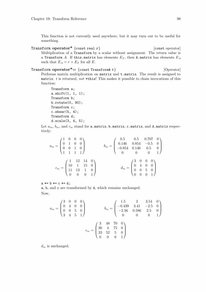
Chapter 19: Transform Reference 98
This function is not currently used anywhere, but it may turn out to be useful forsomething.
[const operator]Transform operator* (const real r )Multiplication of a Transform by a scalar without assignment. The return value isa Transform A. If this.matrix has elements ET , then A.matrix has elements EA
such that EA = r ×ET for all E.
[Operator]Transform operator*= (const Transform& t )Performs matrix multiplication on matrix and t.matrix. The result is assigned tomatrix. t is returned, not *this! This makes it possible to chain invocations of thisfunction:
Transform a;
a.shift(1, 1, 1);
Transform b;
b.rotate(0, 90);
Transform c;
c.shear(5, 4);
Transform d;
d.scale(3, 4, 5);
Let am, bm, and cm stand for a.matrix, b.matrix, c.matrix, and d.matrix respec-tively:
am =
1 0 0 00 1 0 00 0 1 01 1 1 1
bm =
0.5 0.5 0.707 00.146 0.854 −0.5 0−0.854 0.146 0.5 0
0 0 0 1
cm =
1 12 14 010 1 15 011 13 1 00 0 0 1
dm =
3 0 0 00 4 0 00 0 5 00 0 0 1
a *= b *= c *= d;
a, b, and c are transformed by d, which remains unchanged.
Now,
am =
3 0 0 00 4 0 00 0 5 03 4 5 1
bm =
1.5 2 3.54 0−0.439 3.41 −2.5 0−2.56 0.586 2.5 0
0 0 0 1
cm =
3 48 70 030 4 75 033 52 5 00 0 0 1
dm is unchanged.
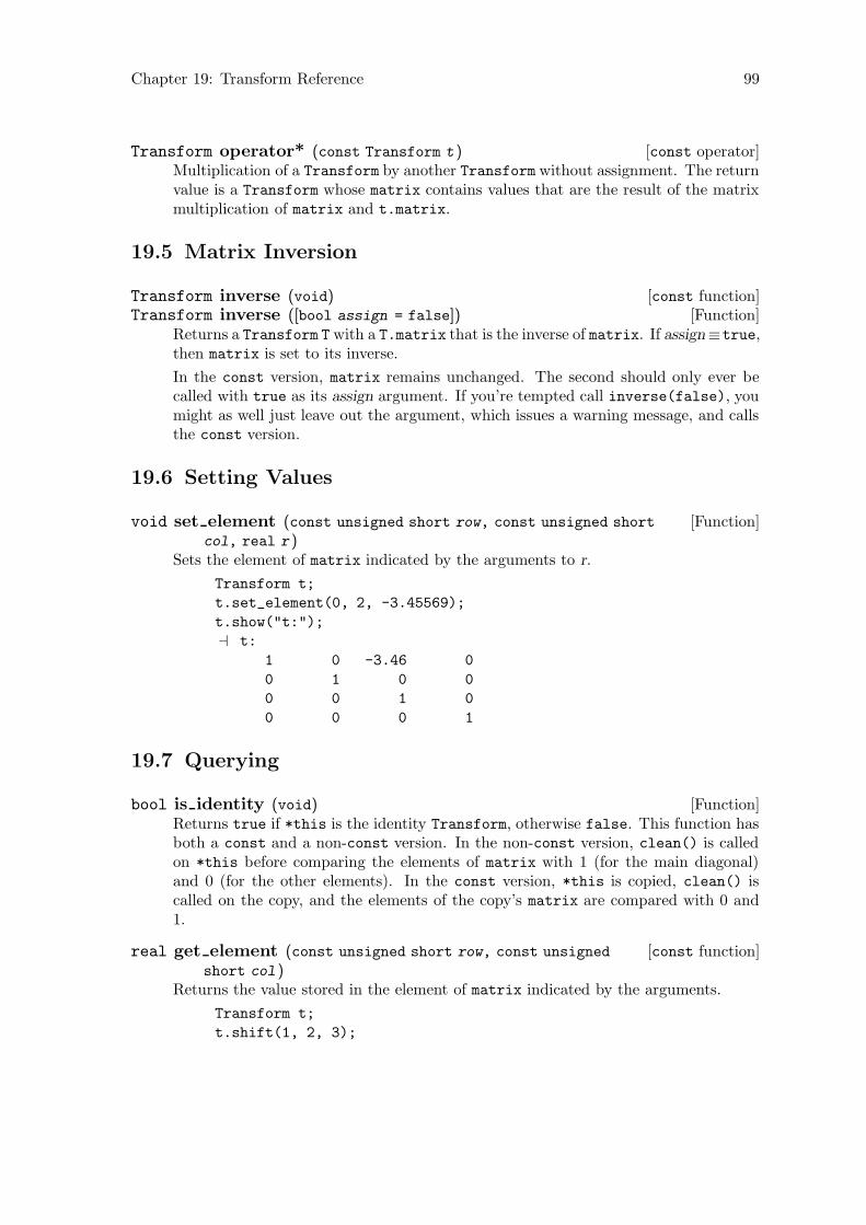
Chapter 19: Transform Reference 99
[const operator]Transform operator* (const Transform t )Multiplication of a Transform by another Transform without assignment. The returnvalue is a Transform whose matrix contains values that are the result of the matrixmultiplication of matrix and t.matrix.
19.5 Matrix Inversion
[const function]Transform inverse (void)[Function]Transform inverse ([bool assign = false])
Returns a Transform T with a T.matrix that is the inverse of matrix. If assign≡true,then matrix is set to its inverse.
In the const version, matrix remains unchanged. The second should only ever becalled with true as its assign argument. If you’re tempted call inverse(false), youmight as well just leave out the argument, which issues a warning message, and callsthe const version.
19.6 Setting Values
[Function]void set element (const unsigned short row, const unsigned short
col, real r )Sets the element of matrix indicated by the arguments to r.
Transform t;
t.set_element(0, 2, -3.45569);
t.show("t:");
a t:
1 0 -3.46 0
0 1 0 0
0 0 1 0
0 0 0 1
19.7 Querying
[Function]bool is identity (void)Returns true if *this is the identity Transform, otherwise false. This function hasboth a const and a non-const version. In the non-const version, clean() is calledon *this before comparing the elements of matrix with 1 (for the main diagonal)and 0 (for the other elements). In the const version, *this is copied, clean() iscalled on the copy, and the elements of the copy’s matrix are compared with 0 and1.
[const function]real get element (const unsigned short row, const unsigned
short col )Returns the value stored in the element of matrix indicated by the arguments.
Transform t;
t.shift(1, 2, 3);
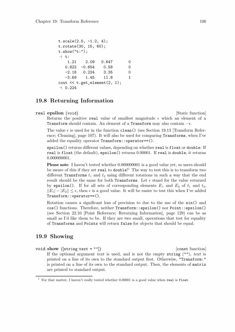
Chapter 19: Transform Reference 100
t.scale(2.5, -1.2, 4);
t.rotate(30, 15, 60);
t.show("t:");
a t:
1.21 2.09 0.647 0
0.822 -0.654 0.58 0
-2.18 0.224 3.35 0
-3.69 1.45 11.8 1
cout << t.get_element(2, 1);
a 0.224
19.8 Returning Information
[Static function]real epsilon (void)Returns the positive real value of smallest magnitude ε which an element of aTransform should contain. An element of a Transform may also contain −ε.
The value ε is used for in the function clean() (see Section 19.13 [Transform Refer-ence; Cleaning], page 107). It will also be used for comparing Transforms, when I’veadded the equality operator Transform::operator==().
epsilon() returns different values, depending on whether real is float or double: Ifreal is float (the default), epsilon() returns 0.00001. If real is double, it returns0.000000001.
Please note: I haven’t tested whether 0.000000001 is a good value yet, so users shouldbe aware of this if they set real to double!1 The way to test this is to transform twodifferent Transforms t1 and t2 using different rotations in such a way that the endresult should be the same for both Transforms. Let ε stand for the value returnedby epsilon(). If for all sets of corresponding elements E1 and E2 of t1 and t2,||E1| − |E2|| ≤ ε, then ε is a good value. It will be easier to test this when I’ve addedTransform::operator==().
Rotation causes a significant loss of precision to due to the use of the sin() andcos() functions. Therefore, neither Transform::epsilon() nor Point::epsilon()(see Section 22.10 [Point Reference; Returning Information], page 129) can be assmall as I’d like them to be. If they are two small, operations that test for equalityof Transforms and Points will return false for objects that should be equal.
19.9 Showing
[const function]void show ([string text = ""])If the optional argument text is used, and is not the empty string (""), text isprinted on a line of its own to the standard output first. Otherwise, "Transform:"is printed on a line of its own to the standard output. Then, the elements of matrixare printed to standard output.
1 For that matter, I haven’t really tested whether 0.00001 is a good value when real is float.

Chapter 19: Transform Reference 101
Transform t;
t.show("t:");
a t:
1 0 0 0
0 1 0 0
0 0 1 0
0 0 0 1
t.scale(1, 2, 3);
t.shift(1, 1, 1);
t.rotate(90, 90, 90);
t.show("t:");
a t:
0 0 1 0
0 2 0 0
-3 0 0 0
-1 1 1 1
19.10 Affine Transformations
The affine transformation functions use their arguments to create a new Transform t (localto the function) representing the appropriate transformation. Then, *this is multipliedby t and t is returned. Returning t instead of *this makes it possible to put the affinetransformation function at the end of a chain of invocations of Transform::operator*=():
Transform t0, t1, t2, t3;
...
t0 *= t1 *= t2 *= t3.scale(2, 3.5, 9);
t0, t1, and t2 are all multiplied by the Transform with
matrix =
2 0 0 00 3.5 0 00 0 9 00 0 0 1
representing the scaling operation, not t3, which may represent a combination of transfor-mations.
[Function]Transform scale (real x, [real y = 1, [real z = 1]])Creates a Transform t representing the scaling operation locally, multiplies *this byt, and returns t. A Transform representing scaling only, when applied to a Point p,will cause its x-coordinate to be multiplied by x, its y-coordinate to be multiplied byy, and its z-coordinate to be multiplied by z.
Transform t;
t.scale(x, y, z);
⇒ t.matrix =
x 0 0 00 y 0 00 0 z 00 0 0 1
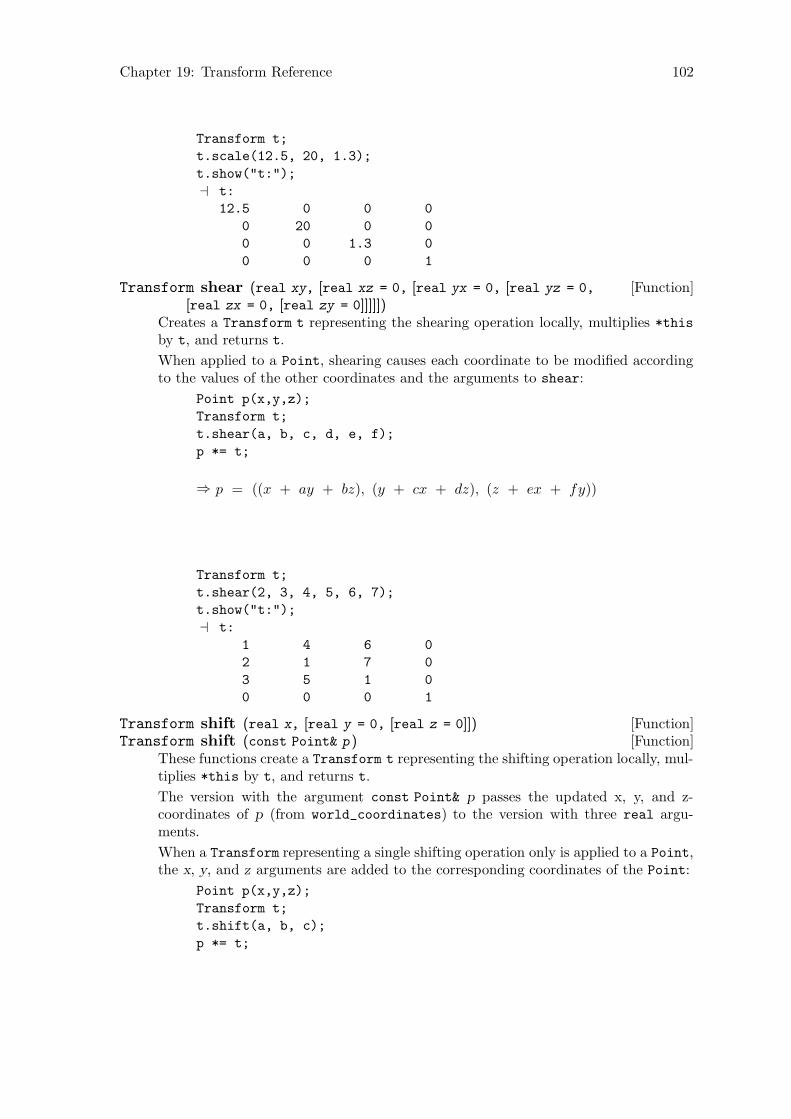
Chapter 19: Transform Reference 102
Transform t;
t.scale(12.5, 20, 1.3);
t.show("t:");
a t:
12.5 0 0 0
0 20 0 0
0 0 1.3 0
0 0 0 1
[Function]Transform shear (real xy, [real xz = 0, [real yx = 0, [real yz = 0,
[real zx = 0, [real zy = 0]]]]])Creates a Transform t representing the shearing operation locally, multiplies *this
by t, and returns t.
When applied to a Point, shearing causes each coordinate to be modified accordingto the values of the other coordinates and the arguments to shear:
Point p(x,y,z);
Transform t;
t.shear(a, b, c, d, e, f);
p *= t;
⇒ p = ((x + ay + bz), (y + cx + dz), (z + ex + fy))
Transform t;
t.shear(2, 3, 4, 5, 6, 7);
t.show("t:");
a t:
1 4 6 0
2 1 7 0
3 5 1 0
0 0 0 1
[Function]Transform shift (real x, [real y = 0, [real z = 0]])[Function]Transform shift (const Point& p )
These functions create a Transform t representing the shifting operation locally, mul-tiplies *this by t, and returns t.
The version with the argument const Point& p passes the updated x, y, and z-coordinates of p (from world_coordinates) to the version with three real argu-ments.
When a Transform representing a single shifting operation only is applied to a Point,the x, y, and z arguments are added to the corresponding coordinates of the Point:
Point p(x,y,z);
Transform t;
t.shift(a, b, c);
p *= t;
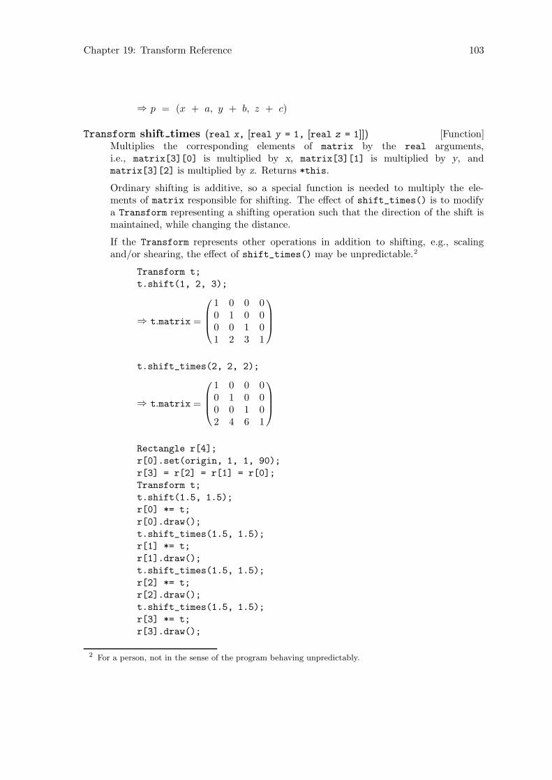
Chapter 19: Transform Reference 103
⇒ p = (x + a, y + b, z + c)
[Function]Transform shift times (real x, [real y = 1, [real z = 1]])Multiplies the corresponding elements of matrix by the real arguments,i.e., matrix[3][0] is multiplied by x, matrix[3][1] is multiplied by y, andmatrix[3][2] is multiplied by z. Returns *this.
Ordinary shifting is additive, so a special function is needed to multiply the ele-ments of matrix responsible for shifting. The effect of shift_times() is to modifya Transform representing a shifting operation such that the direction of the shift ismaintained, while changing the distance.
If the Transform represents other operations in addition to shifting, e.g., scalingand/or shearing, the effect of shift_times() may be unpredictable.2
Transform t;
t.shift(1, 2, 3);
⇒ t.matrix =
1 0 0 00 1 0 00 0 1 01 2 3 1
t.shift_times(2, 2, 2);
⇒ t.matrix =
1 0 0 00 1 0 00 0 1 02 4 6 1
Rectangle r[4];
r[0].set(origin, 1, 1, 90);
r[3] = r[2] = r[1] = r[0];
Transform t;
t.shift(1.5, 1.5);
r[0] *= t;
r[0].draw();
t.shift_times(1.5, 1.5);
r[1] *= t;
r[1].draw();
t.shift_times(1.5, 1.5);
r[2] *= t;
r[2].draw();
t.shift_times(1.5, 1.5);
r[3] *= t;
r[3].draw();
2 For a person, not in the sense of the program behaving unpredictably.

Chapter 19: Transform Reference 104
r0
r1
r2
r3
Figure 73.
Cuboid c(origin, 1, 1, 1);
c.draw();
Transform t;
t.rotate(30, 30, 30);
t.shift(1, 0, 1);
c *= t;
c.draw();
t.shift_times(1.5, 0, 1.5);
c *= t;
c.draw();
t.shift_times(1.5, 0, 1.5);
c *= t;
c.draw();
t.shift_times(1.5, 0, 1.5);
c *= t;
c.draw();
t.shift_times(1.5, 0, 1.5);
c *= t;
c.draw();

Chapter 19: Transform Reference 105
Figure 74.
[Function]Transform rotate (real x, [real y = 0, [real z = 0]])Rotation around the main axes. Creates a Transform t representing the rotation,multiplies *this by t, and returns t.
[Function]Transform rotate (Point p0, Point p1, [const real angle = 180])Rotation around an arbitrary axis. The Point arguments represent the end points ofthe axis, and angle is the angle of rotation. Since 180◦ rotation is needed so often,180 is the default for angle.
[Function]Transform rotate (const Path& p, [const real angle = 180])Rotation around an arbitrary axis. Path argument. The Path p must be linear, i.e.,p.is_linear() must return true. See Section 26.15 [Path Reference; Querying],page 194.
19.11 Alignment with an Axis
[Function]Transform align with axis (Point p0, Point p1, [char axis = ’z’])Returns the Transform that would align the line through p0 and p1 with the majoraxis denoted by the axis argument. The default is the z-axis. This function is usedin the functions that find intersections.
Point P0(1, 1, 1);
Point P1(2, 3, 4);
P0.draw(P1);
P0.dotlabel("$P_0$");
P1.dotlabel("$P_1$");
Transform t;
t.align_with_axis(P0, P1, ’z’);
P0 *= P1 *= t;
t.show("t:");
a t:
0.949 -0.169 0.267 0
0 0.845 0.535 0

Chapter 19: Transform Reference 106
-0.316 -0.507 0.802 0
-0.632 -0.169 -1.6 1
P0.show("P0:");
a P0: (0, 0, 0)
P1.show("P1:");
a P1: (0, 0, 3.74)
The following example shows how align_with_axis() can be used for putting planefigures into a major plane.
default_focus.set(2, 3, -10, 2, 3, 10, 10);
Circle c(origin, 3, 75, 25, 6);
c.shift(2, 3);
c.draw();
Point n = c.get_normal();
n.shift(c.get_center());
Transform t;
t.align_with_axis(c.get_center(), n, ’y’);
t.show("t:");
a t:
0.686 0.379 -0.621 0
0.543 0.3 0.784 0
0.483 -0.875 0 0
-3 -1.66 -1.11 1
n *= c *= t;
c.draw();
c.show("c:");
a c:
fill_draw_value == 0
(1.31, 0, -0.728) .. (1.49, 0, -0.171) ..
(1.44, 0, 0.413) .. (1.17, 0, 0.933) ..
(0.728, 0, 1.31) .. (0.171, 0, 1.49) ..
(-0.413, 0, 1.44) .. (-0.933, 0, 1.17) ..
(-1.31, 0, 0.728) .. (-1.49, 0, 0.171) ..
(-1.44, 0, -0.413) .. (-1.17, 0, -0.933) ..
(-0.728, 0, -1.31) .. (-0.171, 0, -1.49) ..
(0.413, 0, -1.44) .. (0.933, 0, -1.17) .. cycle;
n.show("n:");
a n: (0, 1, 0)
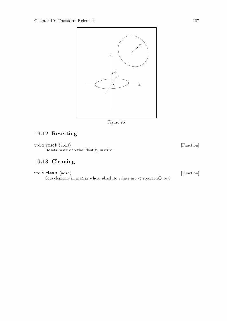
Chapter 19: Transform Reference 107
c
~n
c
~n
x
y
z
Figure 75.
19.12 Resetting
[Function]void reset (void)Resets matrix to the identity matrix.
19.13 Cleaning
[Function]void clean (void)Sets elements in matrix whose absolute values are < epsilon() to 0.
Chapter 20: Label Reference 108
20 Label Reference
Class Label is defined in ‘pictures.web’. Point and Picture are friends of Label.
Labels can be included in drawings by using the label() and dotlabel() functions,which are currently defined for the classes Point and Path, and the classes derived fromthem. See Section 22.19 [Point Reference; Labelling], page 147, and See Section 26.13 [PathReference; Labelling], page 191. They are currently not defined for Solid, and its derivedclasses. I plan to add them for Solid soon.
Users will normally never need to declare objects of type Label, access its data membersor call its member functions directly.
When label() or dotlabel() is invoked, one or more Labels is allocated dynamicallyand pointers to the new Labels are placed onto the vector<Label*> labels of a Picture:current_picture, by default. There are no explicitly defined constructors for Label, noris it intended that Labels ever be created in any way other than through label() ordotlabel(). When a Picture is copied, the Labels are copied, too, and when a Picture iscleared (using Picture::clear()) or destroyed, the Labels are deallocated and destroyed.
20.1 Data Members
[Private variable]Point* ptA pointer to the Point representing the location of the Label.
[Private variable]bool dottrue if the label should be dotted, otherwise false.
dot will be false, if the label was generated by a call to label() with the “dot” ar-gument false (the default), true, if the label was generated by a call to dotlabel(),or to label() with the “dot” argument true.
[Private variable]string textThe text of the label. text is always put between “btex” and “etex” in the MetaPostcode, so that TEX will be used to format the labels. In particular, this means thatTEX’s math mode can be used. However, double backslashes must be used instead ofsingle backslashes, in order that single backslashes be written to out_stream.
Point P(1, 1, 2);
origin.drawarrow(P);
P.label("$\\vec{P}$");
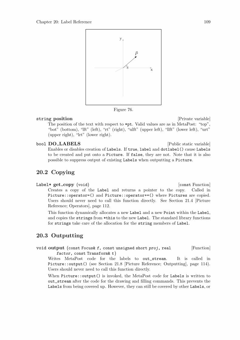
Chapter 20: Label Reference 109
~P
x
y
z
Figure 76.
[Private variable]string positionThe position of the text with respect to *pt. Valid values are as in MetaPost: “top”,“bot” (bottom), “lft” (left), “rt” (right), “ulft” (upper left), “llft” (lower left), “urt”(upper right), “lrt” (lower right).
[Public static variable]bool DO LABELSEnables or disables creation of Labels. If true, label and dotlabel() cause Labelsto be created and put onto a Picture. If false, they are not. Note that it is alsopossible to suppress output of existing Labels when outputting a Picture.
20.2 Copying
[const Function]Label* get copy (void)Creates a copy of the Label and returns a pointer to the copy. Called inPicture::operator=() and Picture::operator+=() where Pictures are copied.Users should never need to call this function directly. See Section 21.4 [PictureReference; Operators], page 112.
This function dynamically allocates a new Label and a new Point within the Label,and copies the strings from *this to the new Label. The standard library functionsfor strings take care of the allocation for the string members of Label.
20.3 Outputting
[Function]void output (const Focus& f, const unsigned short proj, real
factor, const Transform& t )Writes MetaPost code for the labels to out_stream. It is called inPicture::output() (see Section 21.8 [Picture Reference; Outputting], page 114).Users should never need to call this function directly.
When Picture::output() is invoked, the MetaPost code for Labels is written toout_stream after the code for the drawing and filling commands. This prevents theLabels from being covered up. However, they can still be covered by other Labels, or

Chapter 20: Label Reference 110
by Shapes or Labels from subsequent invocations of Picture::output() within thesame figure (see Section 17.2 [I/O Functions], page 92, for descriptions of beginfig()and endfig()).
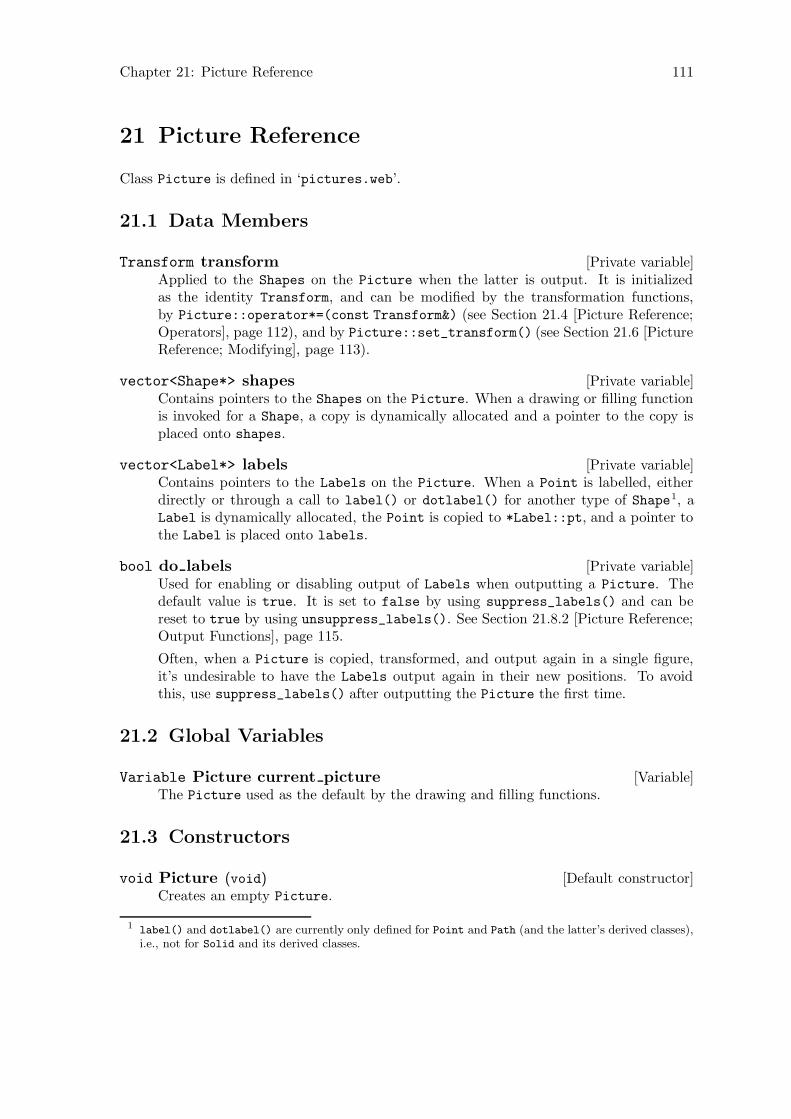
Chapter 21: Picture Reference 111
21 Picture Reference
Class Picture is defined in ‘pictures.web’.
21.1 Data Members
[Private variable]Transform transformApplied to the Shapes on the Picture when the latter is output. It is initializedas the identity Transform, and can be modified by the transformation functions,by Picture::operator*=(const Transform&) (see Section 21.4 [Picture Reference;Operators], page 112), and by Picture::set_transform() (see Section 21.6 [PictureReference; Modifying], page 113).
[Private variable]vector<Shape*> shapesContains pointers to the Shapes on the Picture. When a drawing or filling functionis invoked for a Shape, a copy is dynamically allocated and a pointer to the copy isplaced onto shapes.
[Private variable]vector<Label*> labelsContains pointers to the Labels on the Picture. When a Point is labelled, eitherdirectly or through a call to label() or dotlabel() for another type of Shape1, aLabel is dynamically allocated, the Point is copied to *Label::pt, and a pointer tothe Label is placed onto labels.
[Private variable]bool do labelsUsed for enabling or disabling output of Labels when outputting a Picture. Thedefault value is true. It is set to false by using suppress_labels() and can bereset to true by using unsuppress_labels(). See Section 21.8.2 [Picture Reference;Output Functions], page 115.
Often, when a Picture is copied, transformed, and output again in a single figure,it’s undesirable to have the Labels output again in their new positions. To avoidthis, use suppress_labels() after outputting the Picture the first time.
21.2 Global Variables
[Variable]Variable Picture current pictureThe Picture used as the default by the drawing and filling functions.
21.3 Constructors
[Default constructor]void Picture (void)Creates an empty Picture.
1 label() and dotlabel() are currently only defined for Point and Path (and the latter’s derived classes),i.e., not for Solid and its derived classes.
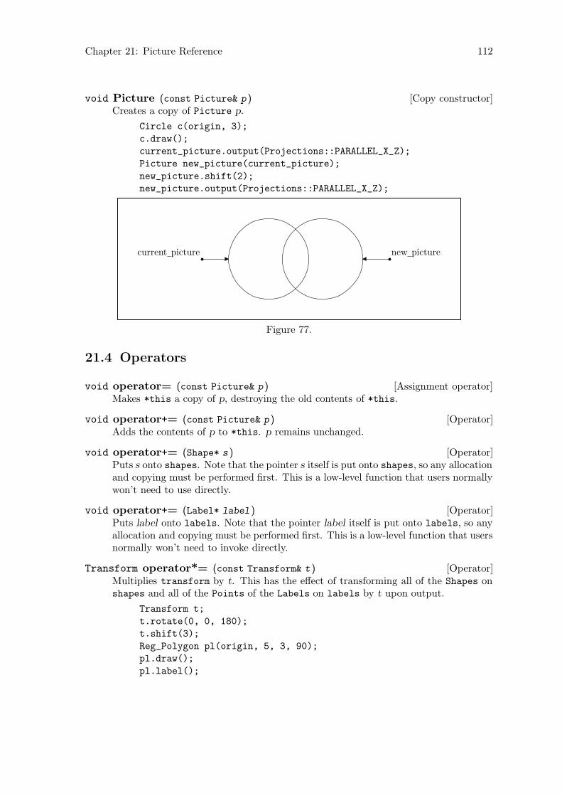
Chapter 21: Picture Reference 112
[Copy constructor]void Picture (const Picture& p )Creates a copy of Picture p.
Circle c(origin, 3);
c.draw();
current_picture.output(Projections::PARALLEL_X_Z);
Picture new_picture(current_picture);
new_picture.shift(2);
new_picture.output(Projections::PARALLEL_X_Z);
current picture new picture
Figure 77.
21.4 Operators
[Assignment operator]void operator= (const Picture& p )Makes *this a copy of p, destroying the old contents of *this.
[Operator]void operator+= (const Picture& p )Adds the contents of p to *this. p remains unchanged.
[Operator]void operator+= (Shape* s )Puts s onto shapes. Note that the pointer s itself is put onto shapes, so any allocationand copying must be performed first. This is a low-level function that users normallywon’t need to use directly.
[Operator]void operator+= (Label* label )Puts label onto labels. Note that the pointer label itself is put onto labels, so anyallocation and copying must be performed first. This is a low-level function that usersnormally won’t need to invoke directly.
[Operator]Transform operator*= (const Transform& t )Multiplies transform by t. This has the effect of transforming all of the Shapes onshapes and all of the Points of the Labels on labels by t upon output.
Transform t;
t.rotate(0, 0, 180);
t.shift(3);
Reg_Polygon pl(origin, 5, 3, 90);
pl.draw();
pl.label();
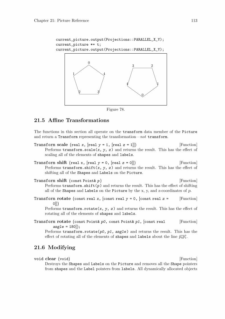
Chapter 21: Picture Reference 113
current_picture.output(Projections::PARALLEL_X_Y);
current_picture *= t;
current_picture.output(Projections::PARALLEL_X_Y);
0
1
2 3
4
0
1
23
4
Figure 78.
21.5 Affine Transformations
The functions in this section all operate on the transform data member of the Picture
and return a Transform representing the transformation—not transform.
[Function]Transform scale (real x, [real y = 1, [real z = 1]])Performs transform.scale(x, y, z) and returns the result. This has the effect ofscaling all of the elements of shapes and labels.
[Function]Transform shift (real x, [real y = 0, [real z = 0]])Performs transform.shift(x, y, z) and returns the result. This has the effect ofshifting all of the Shapes and Labels on the Picture.
[Function]Transform shift (const Point& p )Performs transform.shift(p) and returns the result. This has the effect of shiftingall of the Shapes and Labels on the Picture by the x, y, and z-coordinates of p.
[Function]Transform rotate (const real x, [const real y = 0, [const real z =
0]])Performs transform.rotate(x, y, z) and returns the result. This has the effect ofrotating all of the elements of shapes and labels.
[Function]Transform rotate (const Point& p0, const Point& p1, [const real
angle = 180]);Performs transform.rotate(p0, p1, angle) and returns the result. This has theeffect of rotating all of the elements of shapes and labels about the line −−→p0p1.
21.6 Modifying
[Function]void clear (void)Destroys the Shapes and Labels on the Picture and removes all the Shape pointersfrom shapes and the Label pointers from labels. All dynamically allocated objects
Chapter 21: Picture Reference 114
are deallocated, namely the Shapes, the Labels, and the Points belonging to theLabels. transform is reset to the identity Transform.
[Function]void reset transform (void)Resets transform to the identity Transform.
[Function]Transform set transform (const Transform& t )Sets transform to t and returns t.
[Function]void kill labels (void)Removes the Labels from the Picture.
21.7 Showing
[Function]void show ([string text = "", [bool stop = false]])Prints information about the Picture to standard output.
show() first prints the string "Showing Picture:" to standard output, followed bytext, if the latter is not the empty string ("")2. Then it calls transform.show(),prints the size of shapes and labels, and the value of do_labels. Then it callsshow() on each of the Shapes on shapes. Since show() is a virtual function inclass Shape, the appropriate show() is called for each Shape, i.e., Point::show()for a Point, Path::show() for a Path, etc. If stop is true, execution stops and theuser is requested to type <RETURN> to continue. Finally, the string "Done showing
picture." is printed to standard output.
[Function]void show transform ([string text = "Transform from Picture:"])Calls transform.show(), passing text as the argument to the latter function.
21.8 Outputting
21.8.1 Namespaces
21.8.1.1 Namespace Projections
The namespace Projections is defined in ‘pictures.web’.
[Constant]const unsigned short PERSP[Constant]const unsigned short PARALLEL X Y[Constant]const unsigned short PARALLEL X Z[Constant]const unsigned short PARALLEL Z Y[Constant]const unsigned short AXON[Constant]const unsigned short ISO
These constants can be used for the projection argument in Picture::output(),described in Section 21.8.2 [Picture Reference; Outputting; Functions], page 115,below.
2 Actually, it’s printed to standard output even if it is the empty string, you just don’t see it.
Chapter 21: Picture Reference 115
21.8.1.2 Namespace Sorting
The namespace Sorting is defined in ‘pictures.web’.
[Constant]const unsigned short NO SORT[Constant]const unsigned short MAX Z[Constant]const unsigned short MIN Z[Constant]const unsigned short MEAN Z
These constants can be used for the sort value argument in Picture::output(),described in Section 21.8.2 [Picture Reference; Outputting; Functions], page 115,below.
21.8.2 Output Functions
[Function]void output (const Focus& f, [const unsigned short projection =
Projections::PERSP, [real factor = 1, [const unsigned short sort_value
= Sorting::MAX_Z, [const bool do_warnings = true, [const real
min_x_proj = -40, [const real max_x_proj = 40, [const real min_y_proj =
-40, [const real max_y_proj = 40, [const real min_z_proj = -40, [constreal max_z_proj = 40]]]]]]]]]])
[Function]void output ([const unsigned short projection =
Projections::PERSP, [real factor = 1, [const unsigned short sort_value
= Sorting::MAX_Z, [const bool do_warnings = true, [const real
min_x_proj = -40, [const real max_x_proj = 40, [const real min_y_proj =
-40, [const real max_y_proj = 40, [const real min_z_proj = -40, [constreal max_z_proj = 40]]]]]]]]]])
These functions create a two-dimensional projection of the objects on the Picture
and write MetaPost code to out_stream for drawing it.
The arguments:
const Focus& f
The Focus used for projection, also known as the center of projection, orthe camera. This argument is used in the first version only. The secondversion, without a const Focus& f argument, merely calls the first versionand passes it the global variable default_focus as its first argument, sodefault_focus is effectively the default for f. Defining two versions inthis way makes it possible to call output() with projection as its first(and possibly only) argument. If instead, f were an optional argumentwith default_focus as its default, this wouldn’t have been possible. Italso wouldn’t be possible to have f have a default in the first version, andto retain the second version, because the compiler wouldn’t be able toresolve a call to output() with no arguments.
const unsigned short projection
Default: Projections::PERSP. The type of projection. Valid valuesare const unsigned shorts defined in namespace Projections (see Sec-tion 21.8.1.1 [Namespace Projections], page 114):PERSP for the perspective projection,
Chapter 21: Picture Reference 116
PARALLEL_X_Y for parallel projection onto the x-y plane,PARALLEL_X_Z for parallel projection onto the x-z plane, andPARALLEL_Z_Y for parallel projection onto the z-y plane. %% !! TO DO:I plan to add isometric and axionometric projections soon.
real factor
Default: 1. Passed from output() to extract() and from there toproject(). The world_coordinates of the Points that are projectedare multiplied by factor, which enlarges or shrinks the projected imagewithout altering the Picture itself. factor is probably most useful forparallel projections, where the Focus f isn’t used; with a perspectiveprojection, the parameters of the Focus can be used to influence the sizeof the projected image.
const unsigned short sort value
Default: Sorting::MAX_Z. The value used should be one of the con-stants defined in namespace Sorting, See Section 21.8.1.2 [NamespaceSorting], page 115, above. If MAX_Z (the default) is used, the Shapes
on the Picture are sorted according to the maximum z-value of theprojective_extremes of the Points belonging to the Shape. If MIN_Zis used, they are sorted according to the minimum z-value, and if MEAN_Zis used, they are sorted according to the mean of the maximum and min-imum z-values. If NO_SORT is used, the Shapes are output in the order inwhich they were put onto the Picture.
The surface hiding algorithm implemented in 3DLDF is quite primitive,and doesn’t always work right. For Shapes that intersect, it can’t workright. I plan to work on improving the surface hiding algorithm soon.This is not a trivial problem. To solve it properly, each Shape on aPicture must be tested for intersection with every other Shape on thePicture. If two or more Shapes intersect, they must be broken up intosmaller objects until there are no more intersections. I don’t expect tohave a proper solution soon, but I expect that I will be able to make someimprovements. See Section 9.3 [Surface Hiding], page 67.
const bool do warnings
Default: true. If true, output() issues warnings to stderr (standarderror output) if a Shape cannot be output because it lies outside thelimits set by the following arguments. Sometimes, a user may only wantto project a portion of a Picture, in which case such warnings would notbe helpful. In this case, do warnings should be false.
const real min x proj
Default: -40. The minimum x-coordinate of the projection of a Shape
such that the Shape can be output. If projective_coordinates[0] ofany Point on a Shape is less than min x proj, the Shape will not beprojected at all.
const real max x proj
Default: 40. The maximum x-coordinate of the projection of a Shape
such that the Shape can be output. If projective_coordinates[0] of

Chapter 21: Picture Reference 117
any Point on a Shape is greater than max x proj, the Shape will not beprojected at all.
const real min y proj
Default: -40. The minimum y-coordinate of the projection of a Shape
such that the Shape can be output. If projective_coordinates[1] ofany Point on a Shape is less than min y proj, the Shape will not beprojected at all.
const real max y proj
Default: 40. The maximum y-coordinate of the projection of a Shape
such that the Shape can be output. If projective_coordinates[1] ofany Point on a Shape is greater than max y proj, the Shape will not beprojected at all.
const real min z proj
Default: -40. The minimum z-coordinate of the projection of a Shape
such that the Shape can be output. If projective_coordinates[2] ofany Point on a Shape is less than min z proj, the Shape will not beprojected at all.
const real max z proj
Default: 40. The maximum z-coordinate of the projection of a Shape
such that the Shape can be output. If projective_coordinates[2] ofany Point on a Shape is greater than max z proj, the Shape will not beprojected at all.
[Function]void suppress labels (void)Suppresses output of the Labels on a Picture when output() is called. This can beuseful when a Picture is output, transformed, and output again, one or more times,in a single figure. Usually, it will not be desirable to have the Labels output morethan once.
In Fig. 79, current_picture is output three times, but the Labels on it are onlyoutput once.
Ellipse e(origin, 3, 5);
e.label();
e.draw();
Point pt0(-3);
Point pt1(3);
pt0.draw(pt1);
Point pt2(0, 0, -4);
Point pt3(0, 0, 4);
pt2.draw(pt3);
pt0.dotlabel("0", "lft");
pt1.dotlabel("1", "rt");
pt2.dotlabel("2", "bot");
pt3.dotlabel("3");
current_picture.output(Projections::PARALLEL_X_Z);
current_picture.rotate(0, 60);
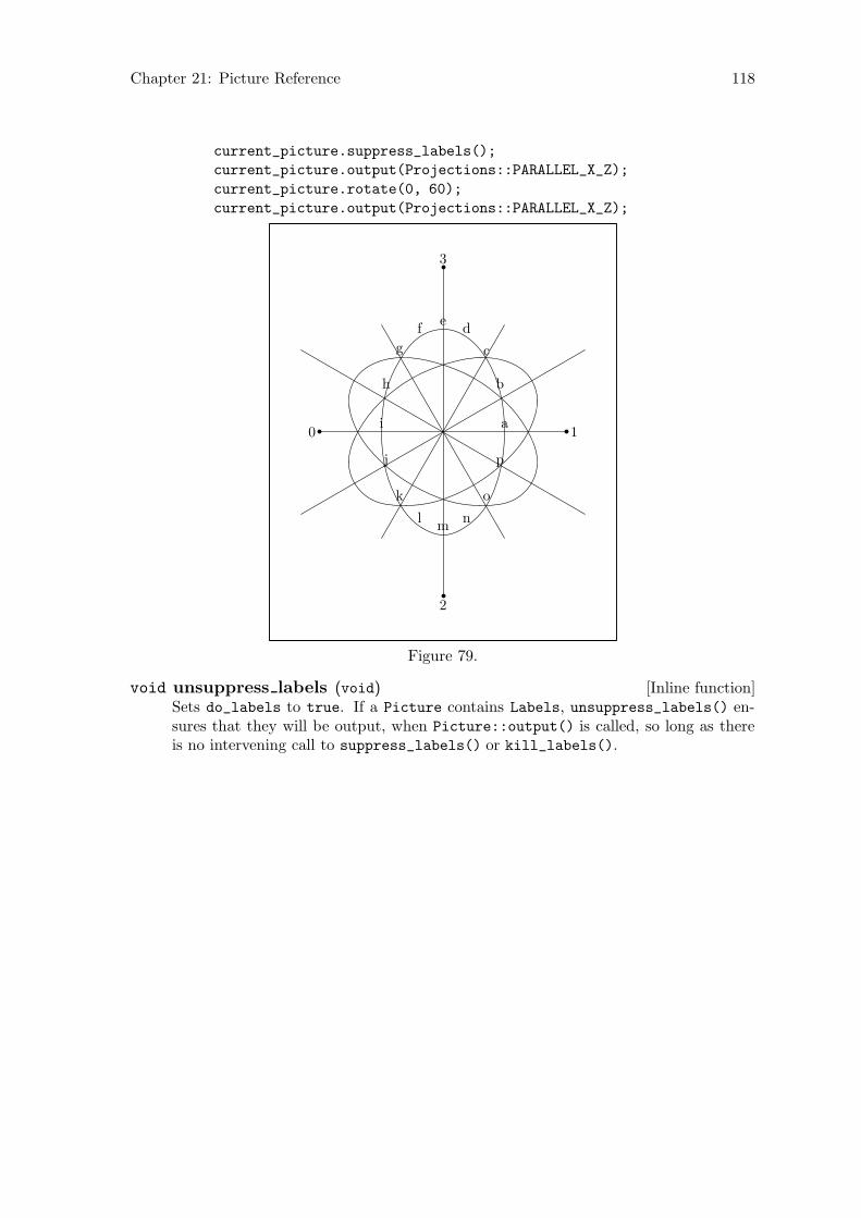
Chapter 21: Picture Reference 118
current_picture.suppress_labels();
current_picture.output(Projections::PARALLEL_X_Z);
current_picture.rotate(0, 60);
current_picture.output(Projections::PARALLEL_X_Z);
a
b
c
de
f
g
h
i
j
k
lm
n
o
p
0 1
2
3
Figure 79.
[Inline function]void unsuppress labels (void)Sets do_labels to true. If a Picture contains Labels, unsuppress_labels() en-sures that they will be output, when Picture::output() is called, so long as thereis no intervening call to suppress_labels() or kill_labels().
Chapter 22: Point Reference 119
22 Point Reference
Class Point is defined in ‘points.web’. It is derived from Shape using protected derivation.The function Transform Transform::align_with_axis(Point, Point, char) is a friendof Point.
22.1 Data Members
[Private variable]valarray<real> world coordinatesThe set of four homogeneous coordinates x, y, z, and w that represent the position ofthe Point within 3DLDF’s global coordinate system.
[Private variable]valarray<real> projective coordinatesThe set of four homogeneous coordinates x, y, z, and w that represent the positionof the projection of the Point onto a two-dimensional plane for output. The x and yvalues are used in the MetaPost code written to out_stream. The z value is used inthe hidden surface algorithm (which is currently rather primitive and doesn’t workvery well. see Section 9.3 [Surface Hiding], page 67). The w value can be 6= 1 ,depending on the projection used; the perspective projection is non-affine, so w cantake on other values.
[Private variable]valarray<real> user coordinatesA set of four homogeneous coordinates x, y, z, and w.
user_coordinates currently has no function. It is intended for use in user-definedcoordinate systems. For example, a coordinate system could be defined with respectto a plane surface that isn’t parallel to one of the major planes. Such a coordinatesystem would be convenient for drawing on the plane. A Transform would make itpossible to convert between user_coordinates and world_coordinates.
[Private variable]valarray<real> view coordinatesA set of four homogeneous coordinates x, y, z, and w.
view_coordinates currently has no function. It may be useful for displaying multipleviews in an interactive graphical user interface, or for some other purpose.
[Private variable]Transform transformContains the product of the transformations applied to the Point. When apply_
transform() is called for the Point, directly or indirectly, the world_coordinates
are updated and transform is reset to the identity Transform. See Section 22.13[Point Reference; Applying Transformations], page 135.
[Private variable]bool on free storeReturns on_free_store. This should only be true if the Point was dynamically allo-cated on the free store. Points should only ever be dynamically allocated by create_
new<Point>(), which uses set_on_free_store() to set on_free_store to true. SeeSection 22.4 [Point Reference; Constructors and Setting Functions], page 123, andSection 22.11 [Point Reference; Modifying], page 130.
Chapter 22: Point Reference 120
[Private variable]signed short drawdot valueUsed to tell Point::output() what MetaPost drawing command (drawdot() orundrawdot()) to write to out_stream when outputting a Point.
When drawdot() or undrawdot() is called on a Point, the Point is copied and putonto the Picture, which was passed to drawdot() or undrawdot() as an argument(current_picture by default). drawdot_value is either set to Shape::DRAWDOT orShape::UNDRAWDOT on the copy; this->drawdot is not set.
[Private variable]const Color* drawdot colorUsed to tell Point::output() what string to write to out_stream for the color whenoutputting a Point.
[Private variable]string penUsed to tell Point::output() what string to write to out_stream for the pen whenoutputting a Point.
[Protected variable]valarray<real> projective extremesA set of 6 real values indicating the maximum and minumum x, y, and z-coordinatesof the Point. Used for determining whether a Point is projectable with the param-eters of a particular invocation of Picture::output(). See Section 21.8 [PictureReference; Outputting], page 114.
Obviously, the maxima and minima will always be the same for a Point, namely the x,y, and z-coordinates. However, set_extremes() and get_extremes(), the functionsthat access projective_extremes, are pure virtual functions in class Shape, so thePoint versions must be consistent with the versions for other types derived fromShape.
[Protected variable]bool do outputtrue by default. Set to false by suppress_output(), which is called on a Shape
by Picture::output(), if the Shape is not projectable. See Section 21.8 [PictureReference; Outputting], page 114.
[Public static variable]string measurement unitsThe unit of measurement for all distances within a Picture, "cm" (for centimeters)by default. The x and y-coordinates of the projected Points are always followed bymeasurement_units when they’re written to out_stream. Unlike Metafont, units ofmeasurement cannot be indicated for individual coordinates. Nor can measurement_
unit be changed within a Picture.
When I write an input routine, I plan to make it behave the way Metafont does,however, 3DLDF will probably also convert all of the input values to a standard unit,as Metafont does.
[Public static variable]real CURR Y[Public static variable]real CURR Z
Default values for the y and z-coordinate of Points, when the x-coordinate, or the xand y-coordinates only are specified. Both are 0 by default.
Chapter 22: Point Reference 121
These values only used in the constructor and setting function taking one requiredreal value (for the x-coordinate), and two optional real values (for the y and z-coordinates). They are not used when a Point is declared using the default construc-tor with no arguments. In this case, the x, y, and z-coordinates will all be 0. SeeSection 22.4 [Point Reference; Constructors and Setting Functions], page 123.
Point A(1);
A.show("A:");
a A: (1, 0, 0);
CURR_Y = 5;
A.set(2);
A.show("A:");
a A: (2, 5, 0);
CURR_Z = 12;
Point B(3);
B.show("B:");
a B: (3, 5, 12);
Point C;
C.show("C:");
a C: (0, 0, 0);
22.2 Typedefs and Utility Structures
[typedef]point pair first secondSynonymous with pair<Point, Point>.
[struct]bool point b ptb is a bool and pt is a Point. bool_point also contains two constructors and anassignment operator, described below.
[Default constructor]void bool point (void)Creates a bool_point and sets b to false and pt to INVALID_POINT.
[Default constructor]void bool point (bool bb, const Point& ppt )Creates a bool_point and sets b to bb and pt to ppt.
[Assignment operator]void bool point::operator= (const bool_point& bp )Sets b to bp.b and pt to bp.pt.
[typedef]bool point pair first secondSynonymous with pair <bool_point, bool_point>.
[struct]bool point quadruple first second third fourthThis structure contains four bool_points. It also has two constructors and an as-signment operator, described below.
[Default constructor]void bool point quadruple (void)Creates a bool_point_quadruple, and sets first, second, third, and fourth all toINVALID_BOOL_POINT.

Chapter 22: Point Reference 122
[Constructor]void bool point quadruple (bool_point a, bool_point b,
bool_point c, bool_point d )Creates a bool_point_quadruple and sets first to a, second to b, third to c, andfourth to d.
[Assignment operator]void bool point quadruple::operator= (constbool_point_quadruple& arg )
Makes *this a copy of arg.
[struct]bool real point b r ptb is a bool, r is a real, and pt is a Point. bool_real_point also contains threeconstructors and an assignment operator, described below.
[Default constructor]void bool real point (void)Creates a bool_real_point and sets b to false, r to INVALID_REAL and pt toINVALID_POINT.
[Copy constructor]void bool real point (const bool_real_point& brp )Creates a bool_real_point and sets b to brp.b, r to brp.r, and pt to brp.pt.
[Constructor]void bool real point (const bool& bb, const real& rr, const
Point& ppt )Creates a bool_real_point and sets b to bb, r to rr, and pt to ppt.
[Assignment operator]void bool real point::operator= (constbool_real_point& brp )
Makes *this a copy of brp.
22.3 Global Constants and Variables
[Constant]Point INVALID POINTThe x, y, and z-values in world_coordinates are all INVALID_REAL.
[Constant]Point originThe x, y, and z-values in world_coordinates are all 0.
[Constant]bool_point INVALID BOOL POINTb is false and pt is INVALID_POINT.
[Constant]bool_point_pair INVALID BOOL POINT PAIRfirst and second are both INVALID_BOOL_POINT.
[Constant]bool_real_point INVALID BOOL REAL POINTb is false, r is INVALID_REAL, and pt is INVALID_POINT.
[Constant]bool_point_quadrupleINVALID BOOL POINT QUADRUPLE
first, second, third, and fourth are all INVALID_BOOL_POINT.
Chapter 22: Point Reference 123
22.4 Constructors and Setting Functions
[Default constructor]void Point (void)Creates a Point and initializes its x, y, and z-coordinates to 0.
[Constructor]void Point (const real x, [const real y = CURR_Y, [const real z =
CURR_Z]])Creates a Point and initializes its x, y, and z-coordinates to the values of the argu-ments x, y, and z. The arguments y and z are optional. If they are not specified, thevalues of CURR_Y and CURR_Z are used. They are 0 by default, but can be changedby the user. This can be convenient, if all of the Points being drawn in a particularsection of a program have the same z or y and z values.
[Setting function]void set (const real x, [const real y = CURR_Y, [const real z
= CURR_Z]])Corresponds to the constructor above, but is used for resetting the coordinates of anexisting Point.
[Copy constructor]void Point (const Point& p )Creates a Point and copies the values for its x, y, and z-coordinates from p.
[Setting function]void set (const Point& p )Corresponds to the copy constructor above, but is used for resetting the coordinatesof an existing Point. This function exists purely as a convenience; the operatoroperator=() (see Section 22.6 [Point Reference; Operators], page 124) performs ex-actly the same function.
[Template specializations]Point* create new<Point> (const Point* p )Point* create new<Point> (const Point& p )
Pseudo-constructors for dynamic allocation of Points. They create a Point on thefree store and allocate memory for it using new(Point). They return a pointer to thenew Point.
If p is a non-zero pointer or a reference, the new Point will be a copy of p. Ifthe new object is not meant to be a copy of an existing one, ‘0’ must be passedto create_new<Point>() as its argument. See Chapter 14 [Dynamic Allocation ofShapes], page 84, for more information.
One use for create_new<Point> is in the constructors for classes of objects thatcan contain a variable number of Points, such as Path and Polygon. Another use isin the drawing and filling functions, where objects are copied and the copies put ontoa Picture.
Programmers who dynamically allocate Points must ensure that they are deallocatedproperly using delete!

Chapter 22: Point Reference 124
22.5 Destructor
[virtual Destructor]void ~Point (void)This function currently has an empty definition, but its existence prevents GCC 3.3from issuing the following warning: “\thinspace ‘class Point’ has virtual functionsbut non-virtual destructor”.
22.6 Operators
[Assignment operator]void operator= (const Point& p )Makes *this a copy of p.
[Operator]Transform operator*= (const Transform& t )Multiplies transform by t. By multiplying a Point successively by one or moreTransforms, the effect of the transformations is “saved up” in transform. Onlywhen an operation that needs updated values for the world_coordinates is calledon a Point, or the Point is passed as an argument to such an operation, is the transfor-mation stored in transform applied to world_coordinates by apply_transform(),which subsequently, resets transform to the identity Transform. See Section 22.13[Point Reference; Applying Transformations], page 135.
[const operator]Point operator+ (Point p )Returns a Point with world_coordinates that are the sums of the correspondingworld_coordinates of *this and p, after they’ve been updated. *this remainsunchanged; as in many other functions with Point arguments, p is passed by value,because apply_transform() must be called on it, in order to update its world_
coordinates. If p were a const Point&, it would have to copied within the functionanyway, because apply_transform() is a non-const operation.
Point p0(-2, -6, -28);
Point p1(3, 14, 92);
Point p2(p0 + p1);
p2.show("p2:");
a p2: (1, 8, 64)
[Operator]void operator+= (Point p )Adds the updated world_coordinates of p to those of *this. Equivalent ineffect to shift(p) In fact, this function merely calls p.apply_transform()
and Point::shift(real, real, real) with p’s x, y, and z coordinates (fromworld_coordinates) as its arguments. See Section 22.12 [Point Reference; AffineTransformations], page 130.
[const operator]Point operator- (Point p )Returns a Point with world_coordinates representing the difference between theupdated values of this->world_coordinates and p.world_coordinates.
[Operator]void operator-= (Point p )Subtracts the updated values of p.world_coordinates from those of this->world_coordinates.
Chapter 22: Point Reference 125
[Operator]real operator*= (const real r )Multiplies the updated x, y, and z coordinates (world_coordinates) of the Point byr and returns r. This makes it possible to chain invocations of this function.
If P is a Point then P *= r is equivalent in its effect to P.scale(r, r, r), exceptthat P.world_coordinates is modified directly and immediately, without changingP.transform. This is possible, because this function calls apply_transform() to up-date the world_coordinates before multiplying them r, so transform is the identityTransform.
Point P(1, 2, 3);
P *= 7;
P.show("P:");
a P: (7, 14, 21);
Point Q(1.5, 2.7, 13.82);
Q *= P *= -1.28;
P.show("P:");
a P: (-8.96, -17.92, -26.88)
Q.show("Q:");
a Q: (-1.92, -3.456, -17.6896)
[const operator]Point operator* (const real r )Returns a Point with x, y, and z coordinates (world_coordinates) equal to theupdated x, y, and z coordinates of *this multiplied by r.
[Non-member operator]Point operator* (const real r, const Point& p )Equivalent to Point::operator*(const real r) (see above), but with r placed first.
Point p0(10, 11, 12);
real r = 2.5;
Point p1 = r * p0;
p1.show();
a Point:a (25, 27.5, 30)
[const operator]Point operator- (void)Unary minus (prefix). Returns a Point with x, y, and z coordinates (world_coordinates) equal to the the x, y, and z-coordinates (world_coordinates) of*this multiplied by -1.
[Operator]void operator/= (const real r )Divides the updated x, y, and z coordinates (world_coordinates) of the Point by r.
[const operator]Point operator/ (const real r )Returns a Point with x, y, and z coordinates (world_coordinates) equal to theupdated x, y, and z coordinates of *this divided by r.
[Operator]bool operator== (Point p )[const operator]bool operator== (const Point& p )
Equality comparison for Points. These functions return true if the updated valuesof the world_coordinates of the two Points differ by less than the value returned by
Chapter 22: Point Reference 126
Point::epsilon(), otherwise false. See Section 22.10 [Point Reference; ReturningInformation], page 129.
[const operator]bool operator!= (const Point& p )Inequality comparison for Points. Returns false if *this == p , otherwise true.
22.7 Copying
[const function]Shape* get copy (void)Creates a copy of the Point, and allocates memory for it on the free store usingcreate_new<Point>(). It returns a pointer to Shape that points to the new Point.This function is used in the drawing commands for putting Points onto Pictures.See Section 22.18 [Point Reference; Drawing], page 144.
22.8 Querying
[inline function]bool is identity (void)Returns true if transform is the identity Transform.
[const inline function]Transform get transform (void)Returns transform.
[const function]bool is on free store (void)Returns true if memory for the Point has been dynamically allocated on the freestore, i.e., if the Point has been created using create_new<Point>(). See Sec-tion 22.4 [Point Reference; Constructors and Setting Functions], page 123.
[const function]bool is on plane (const Plane& p )Returns true, if the Point lies on the Plane p, otherwise false.
Planes are conceived of as having infinite extension, so while the Point C in Fig. 80does not lie within the Rectangle r, it does lie on q, so C.is_on_plane(q) returnstrue.1
Point P(1, 1, 1);
Rectangle r(P, 4, 4, 20, 45, 35);
Plane q = r.get_plane();
Point A(2, 0, 2);
Point B(2, 1.64143, 2);
Point C(0.355028, 2.2185, 6.48628);
cout << A.is_on_plane(q);
a 0
cout << B.is_on_plane(q);
a 1
cout << "C.is_on_plane(q)";
1 It’s unlikely that Points will lie on a Plane, unless the user constructs the case specially. In Fig. 80, thecoordinates for B and C were found by using Plane::intersection_point(). See Section 25.6 [Planes;Intersections], page 161.

Chapter 22: Point Reference 127
a 1
P
r
A
B
C
x
y
z
Figure 80.
[const function]bool is in triangle (const Point& p0, const Point& p1, const
Point& p2, [bool verbose = false, [bool test_points = true]])Returns true, if *this lies within the triangle determined by the three Point argu-ments, otherwise false.
If the code calling is_in_triangle() has ensured that p0, p1, and p2 determine aplane, i.e., that they are not colinear, and that *this lies in that plane, then false
can be passed to is_in_triangle() as its test points argument.
If the verbose argument is true, information resulting from the execution of thefunction are printed to standard output or standard error.
This function is needed for determining whether a line intersects with a polygon.
22.9 Returning Coordinates
The functions in this section return either a single coordinate or a set of coordinates. Eachhas a const and a non-const version.
The arguments are the same, with one exception:
char c Only in get_coord(). Indicates which coordinate should be returned. Validvalues are ’x’, ’X’, ’y’, ’Y’, ’z’, ’Z’, ’w’, and ’W’.
char coords
Indicates the set of coordinates which should be returned or from which thecoordinate to be returned should be chosen from. Valid values are ’w’ forworld_coordinates (the default), ’p’ for projective_coordinates, ’u’ foruser_coordinates, and ’v’ for view_coordinates.
const bool do persp
Only relevant if projective_coordinates, or one of its elements is to be re-turned. If true, the default, then project() is called, thereby generating
Chapter 22: Point Reference 128
values for projective_coordinates. If do persp is false, then projective_
coordinates, or one of its elements, is returned unchanged, which may some-times be useful.
const bool do apply
If true (the default), apply_transform() is called, thereby updatingthe world_coordinates. Otherwise, it’s not, so that the values storedin world_coordinates remain unchanged. Note that if coords is ’p’
and do persp is true, apply_transform() will be called in project()
whether do_apply is true or false. If for some reason, one wanted getprojective_coordinates, or one of its values, based on the projection ofworld_coordinates without first updating them, one would have to callreset_transform() before calling one of these functions. It would probablybe a good idea to save transform before doing so.
Focus* f Indicates what Focus is to be used for projection. Only relevant if coords is’p’, i.e., projective_coordinates, or one of its elements, is to be returned.The default is 0, in which case f points to the global variable default_focus.
const unsigned short proj
Indicates what form of projection is to be used. Only relevant if coords is ’p’,i.e., projective_coordinates, or one of its elements, is to be returned. Thedefault is Projections::PERSP, which causes the perspective projection to beapplied.
real factor
Passed to project(). The values of the x and y coordinates in projective_
coordinates are multiplied by factor. Only relevant if coords is ’p’, i.e.,projective_coordinates, or one of its elements, is to be returned. The defaultis 1.
[Function]valarray <real> get all coords ([char coords = ’w’, [const bool
do_persp = true, [const bool do_apply = true, [Focus* f = 0, [constunsigned short proj = Projections::PERSP, [real factor = 1]]]]]])
Returns one of the sets of coordinates; world_coordinates by default. Returnsa complete set of coordinates: ’w’ for world_coordinates, ’p’ for projective_
coordinates, ’u’ for user_coordinates, or’v’ for view_coordinates.
[Function]real get coord (char c, [char coords = ’w’, [const bool do_persp =
true, [const bool do_apply = true, [Focus* f = 0, [const unsigned short
proj = Projections::PERSP, [real factor = 1]]]]]])Returns one coordinate, x, y, z, or w, from the set of coordinates indicated (orworld_coordinates, by default).
[Function]real get x ([char coords = ’w’, [const bool do_persp = true, [constbool do_apply = true, [Focus* f = 0, [const unsigned short proj =
Projections::PERSP, [real factor = 1]]]]]])Returns the x-coordinate from the set of coordinates indicated (or world_
coordinates, by default).

Chapter 22: Point Reference 129
[Function]real get y ([char coords = ’w’, [const bool do_persp = true, [constbool do_apply = true, [Focus* f = 0, [const unsigned short proj =
Projections::PERSP, [real factor = 1]]]]]])Returns the y-coordinate from the set of coordinates indicated (or world_
coordinates, by default).
[Function]real get z ([char coords = ’w’, [const bool do_persp = true, [constbool do_apply = true, [Focus* f = 0, [const unsigned short proj =
Projections::PERSP, [real factor = 1]]]]]])Returns the z-coordinate from the set of coordinates indicated (or world_
coordinates, by default).
[Function]real get w ([char coords = ’w’, [const bool do_persp = true, [constbool do_apply = true, [Focus* f = 0, [const unsigned short proj =
Projections::PERSP, [real factor = 1]]]]]])Returns the w-coordinate from the set of coordinates indicated (or world_
coordinates, by default).
22.10 Returning Information
[Static function]real epsilon (void)Returns the positive real value of smallest magnitude ε that should be used as acoordinate value in a Point. A coordinate of a Point may also contain −ε.
The value ε is used for testing the equality of Points in Point::operator==() (seeSection 22.6 [Point Reference; Operators], page 124):
Let ε be the value returned by epsilon(), P and Q be Points, and Px, Qx, Py, Qy,Pz, and Qz the updated x, y, and z-coordinates of P and Q, respectively. If and onlyif ||Px| − |Qx|| < ε, ||Py| − |Qy|| < ε, and ||Pz | − |Qz|| < ε, then P = Q.
epsilon() returns different values, depending on whether real is float or double: Ifreal is float (the default), epsilon() returns 0.00001. If real is double, it returns0.000000001.
Please note: I haven’t tested whether 0.000000001 is a good value yet, so users shouldbe aware of this if they set real to double!2 The way to test this is to start withtwo Points P and Q at different locations. Then they should be transformed usingdifferent rotations in such a way that they should end up at the same location. Let εstand for the value returned by epsilon(), and let x, y, and y stand for the world_
coordinates of the Points after apply_transform() has been called on them. IfxP = xQ, yP = yQ, and zP = zQ, ε is a good value.
Rotation causes a significant loss of precision to due to the use of the sin() andcos() functions. Therefore, neither Point::epsilon() nor Transform::epsilon()(see Section 19.8 [Tranform Reference; Returning Information], page 100) can be assmall as I’d like them to be. If they are two small, operations that test for equalityof Transforms and Points will return false for objects that should be equal.
2 For that matter, I haven’t really tested whether 0.00001 is a good value when real is float.
Chapter 22: Point Reference 130
22.11 Modifying
[Virtual function]bool set on free store ([bool b = true])This function is used in the template function create_new(). It sets on_free_storeto true. See Section 22.1 [Point Reference; Data Members], page 119, and Section 22.4[Point Reference; Constructors and Setting Functions], page 123.
[Function]void clear (void)Sets all of the coordinates in all of the sets of coordinates (i.e., world_coordinates,user_coordinates, view_coordinates, and projective_coordinates) to 0 andresets transform
[Function]void clean ([int factor = 1])Calls apply_transform() and sets the values of world_coordinates to 0, whoseabsolute values are less than epsilon()× factor .
[Function]void reset transform (void)Sets Transform to the identity Transform. Performed in apply_transform(), afterthe latter updates world_coordinates. Section 22.13 [Point Reference; ApplyingTransformations], page 135.
22.12 Affine Transformations
[Function]Transform rotate (const real x, [const real y = 0, [const real z =
0]])[Function]Transform rotate (const Point& p0, const Point& p1, [const real
angle = 180])[Function]Transform rotate (const Path& p, [const real angle = 180])
Each of these functions calls the corresponding version of Transform::rotate(), andreturns its return value, namely, a Transform representing the rotation only.
In the first version, taking three real arguments, the Point is rotated x degreesaround the x-axis, y degrees around the y-axis, and z degrees around the z-axis inthat order.
Point p0(1, 0, 2);
p0.rotate(90);
p0.show("p0:")
a p0: (1, 2, 0)
Point p1(-1, 1, 1);
p1.rotate(-90, 90, 90);
p1.show("pt1:");
a p1: (1, -1, -1)

Chapter 22: Point Reference 131
(1, 0, 2)
(1, 2, 0)
p0(−1, 1, 1)
(1,−1,−1)
p1
x
y
z
Figure 81.
Please note that rotations are not commutative operations. Nor are they commutativewith other transformations. So, if you want to rotate a Point about the x, y andz-axes in that order, you can do so with a single invocation of rotate(), as in theprevious example. However, if you want to rotate a Point first about the y-axis andthen about the x-axis, you must invoke rotate() twice.
Point pt0(1, 1, 1);
pt0.rotate(0, 45);
pt0.rotate(45);
pt0.show("pt0:");
a pt0: (0, 1.70711, 0.292893)
In the version taking two Point arguments p0 and p1, and a real argument angle,the Point is rotated angle degrees around the axis determined by p0 and p1, 180◦
by default.
Point P(2, 0, 0);
Point A;
Point B(2, 2, 2);
P.rotate(A, B, 180);
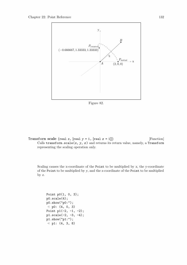
Chapter 22: Point Reference 132
Pinitial
(2, 0, 0)A
B
Protated
(−0.666667, 1.33333, 1.33333)
x
y
z
Figure 82.
[Function]Transform scale (real x, [real y = 1, [real z = 1]])Calls transform.scale(x, y, z) and returns its return value, namely, a Transform
representing the scaling operation only.
Scaling causes the x-coordinate of the Point to be multiplied by x, the y-coordinateof the Point to be multiplied by y, and the z-coordinate of the Point to be multipliedby z.
Point p0(1, 0, 3);
p0.scale(4);
p0.show("p0:");
a p0: (4, 0, 3)
Point p1(-2, -1, -2);
p1.scale(-2, -3, -4);
p1.show("p1:");
a p1: (4, 3, 8)
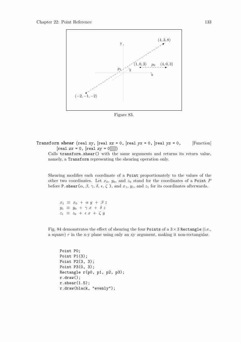
Chapter 22: Point Reference 133
(1, 0, 3) (4, 0, 3)p0
(−2,−1,−2)
(4, 3, 8)
p1
x
y
z
Figure 83.
[Function]Transform shear (real xy, [real xz = 0, [real yx = 0, [real yz = 0,
[real zx = 0, [real zy = 0]]]]])Calls transform.shear() with the same arguments and returns its return value,namely, a Transform representing the shearing operation only.
Shearing modifies each coordinate of a Point proportionately to the values of theother two coordinates. Let x0, y0, and z0 stand for the coordinates of a Point Pbefore P.shear(α, β, γ, δ, ε, ζ ), and x1, y1, and z1 for its coordinates afterwards.
x1 ≡ x0 + α y + β zy1 ≡ y0 + γ x + δ zz1 ≡ z0 + ε x + ζ y
Fig. 84 demonstrates the effect of shearing the four Points of a 3×3 Rectangle (i.e.,a square) r in the x-y plane using only an xy argument, making it non-rectangular.
Point P0;
Point P1(3);
Point P2(3, 3);
Point P3(0, 3);
Rectangle r(p0, p1, p2, p3);
r.draw();
r.shear(1.5);
r.draw(black, "evenly");

Chapter 22: Point Reference 134
P0 = Q0 = (0, 0) P1 = Q1 = (3, 0)
P2 = (3, 3)P3 = (0, 3)
r q
Q2 = (7.5, 3)Q3 = (4.5, 3)
Figure 84.
[Function]Transform shift (real x, [real y = 0, [real z = 0]])[Function]Transform shift (const Point& p )
Each of these functions calls the corresponding version of Transform::shift() ontransform, and returns its return value, namely, a Transform representing the shift-ing operation only.
The Point is shifted x units in the direction of the positive x-axis, y units in thedirection of the positive y-axis, and z units in the direction of the positive z-axis.
p0(1, 2, 3);
p0.shift(2, 3, 5);
p0.show("p0:");
a p0: (3, 5, 8)
[Function]Transform shift times (real x, [real y = 1, [real z = 1]])[Function]Transform shift times (const Point& p )
Each of these functions calls the corresponding version of Transform::shift_
times() on transform and returns its return value, namely the new value oftransform.
shift_times() makes it possible to increase the magnitude of a shift applied to aPoint, while maintaining its direction. Please note that shift_times() will onlyhave an effect if it’s called after a call to shift() and before transform is reset. Thisis performed by reset_transform(), which is called in apply_transform(), and canalso be called directly. See Section 19.12 [Transform Reference; Resetting], page 107,and Section 22.13 [Point Reference; Applying Transformations], page 135.
Point P;
P.drawdot();
P.shift(1, 1, 1);
P.drawdot();
P.shift_times(2, 2, 2);
P.drawdot();
P.shift_times(2, 2, 2);
P.drawdot();
P.shift_times(2, 2, 2);
P.drawdot();
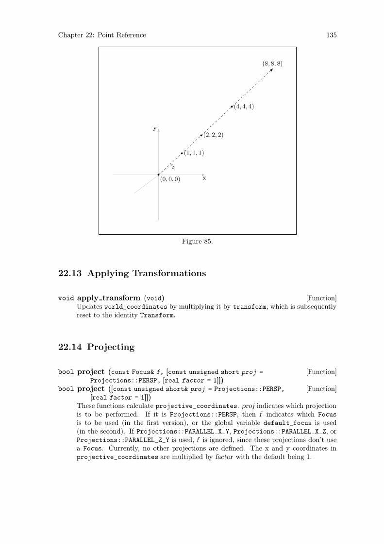
Chapter 22: Point Reference 135
(0, 0, 0)
(1, 1, 1)
(2, 2, 2)
(4, 4, 4)
(8, 8, 8)
x
y
z
Figure 85.
22.13 Applying Transformations
[Function]void apply transform (void)Updates world_coordinates by multiplying it by transform, which is subsequentlyreset to the identity Transform.
22.14 Projecting
[Function]bool project (const Focus& f, [const unsigned short proj =
Projections::PERSP, [real factor = 1]])[Function]bool project ([const unsigned short& proj = Projections::PERSP,
[real factor = 1]])These functions calculate projective_coordinates. proj indicates which projectionis to be performed. If it is Projections::PERSP, then f indicates which Focus
is to be used (in the first version), or the global variable default_focus is used(in the second). If Projections::PARALLEL_X_Y, Projections::PARALLEL_X_Z, orProjections::PARALLEL_Z_Y is used, f is ignored, since these projections don’t usea Focus. Currently, no other projections are defined. The x and y coordinates inprojective_coordinates are multiplied by factor with the default being 1.
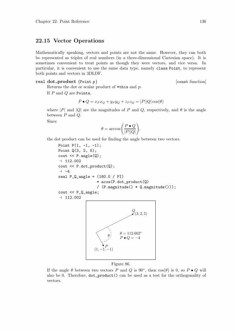
Chapter 22: Point Reference 136
22.15 Vector Operations
Mathematically speaking, vectors and points are not the same. However, they can bothbe represented as triples of real numbers (in a three-dimensional Cartesian space). It issometimes convenient to treat points as though they were vectors, and vice versa. Inparticular, it is convenient to use the same data type, namely class Point, to representboth points and vectors in 3DLDF.
[const function]real dot product (Point p )Returns the dot or scalar product of *this and p.
If P and Q are Points,
P •Q = xP xQ + yP yQ + zP zQ = |P ||Q| cos(θ)
where |P | and |Q| are the magnitudes of P and Q, respectively, and θ is the anglebetween P and Q.
Since
θ = arccos
(
P •Q
|P ||Q|
)
,
the dot product can be used for finding the angle between two vectors.
Point P(1, -1, -1);
Point Q(3, 2, 5);
cout << P.angle(Q);
a 112.002
cout << P.dot_product(Q);
a -4
real P_Q_angle = (180.0 / PI)
* acos(P.dot_product(Q)
/ (P.magnitude() * Q.magnitude()));
cout << P_Q_angle;
a 112.002
P(1,−1,−1)
Q(3, 2, 5)
θθ = 112.002◦
P •Q = −4
Figure 86.
If the angle θ between two vectors P and Q is 90◦, then cos(θ) is 0, so P • Q willalso be 0. Therefore, dot_product() can be used as a test for the orthogonality ofvectors.

Chapter 22: Point Reference 137
Point P(2);
Point Q(P);
Point Q0(P0);
Q0 *= Q.rotate(0, 0, 90);
P *= Q.rotate(0, 45, 45);
P *= Q.rotate(45);
cout << P.angle(Q);
a 90
cout << P.dot_product(Q);
a 0
P(1, 1.70711, 0.292893)
Q
(−1.41421, 1,−1)90◦
Figure 87.
[const function]Point cross product (Point p )Returns the cross or vector product of *this and p.
If P and Q are Points,
P ×Q = ((yP zQ − zP yQ), (zP xQ − xP zQ), (xP yQ − yP xQ)) = |P ||Q| sin(θ)n,
where |P | and |Q| are the magnitudes of P and Q, respectively, θ is the angle betweenP and Q, and n is a unit vector perpendicular to both P and Q in the direction ofa right-hand screw from P towards Q. Therefore, cross_product() can be used tofind the normals to planes.
Point P(2, 2, 2);
Point Q(-2, 2, 2);
Point n = P.cross_product(Q);
n.show("n:");
a n: (0, -8, 8)
real theta = (PI / 180.0) * P.angle(Q);
cout << theta;
a 1.23096
real n_mag = P.magnitude() * Q.magnitude() * sin(theta);
cout << n_mag;
a 11.3137
n /= n_mag;
cout << n.magnitude();
a 1

Chapter 22: Point Reference 138
P(2, 2, 2)
Q(−2, 2, 2)
~n
(0,−8, 8)
θ θ = 70.5288◦
Figure 88.
If θ = 0◦ or 180◦, sin(θ) will be 0, and P ×Q will be (0, 0, 0). The cross product thusprovides a test for parallel vectors.
Point P(1, 2, 1);
Point Q(P);
Point R;
R *= Q.shift(-3, -1, 1);
Point s(Q - R);
Point n = P.cross_product(s);
n.show("n:");
a n: (0, 0, 0)
~s
origin
P
Q
R
Figure 89.
[const function]real magnitude (void)Returns the magnitude of the Point. This is its distance from origin and is equal
to√
x2 + y2 + z2.
Point P(13, 15.7, 22);
cout << P.magnitude();
a 29.9915

Chapter 22: Point Reference 139
[const function]real angle (Point p )Returns the angle in degrees between two Points.
Point P(3.75, -1.25, 6.25);
Point Q(-5, 2.5, 6.25);
real angle = P.angle(Q);
cout << angle;
a 73.9084
Point n = origin.get_normal(P, Q);
n.show("n:");
a n: (0.393377, 0.91788, -0.0524503)
P
Q
~nθ
θ = 73.9084◦
x
y
z
Figure 90.
[Function]Point unit vector (const bool assign, [const bool silent = false ])[const function]Point unit vector (void)
These functions return a Point with the x, y, and z-coordinates of world_
coordinates divided by the magnitude of the Point. The magnitude of theresulting Point is thus 1. The first version assigns the result to *this and shouldonly ever be called with assign = true. Calling it with the argument false isequivalent to calling the const version, with no assignment. If unit_vector() iscalled with assign and silent both false, it issues a warning message is issued andthe const version is called. If silent is true, the message is suppressed.
Point P(21, 45.677, 91);
Point Q = P.unit_vector();
Q.show("Q:");
a Q: (0.201994, 0.439357, 0.875308)
P.rotate(30, 25, 10);
P.show("P:");
P: (-19.3213, 82.9627, 59.6009)
cout << P.magnitude();
a 103.963
P.unit_vector(true);
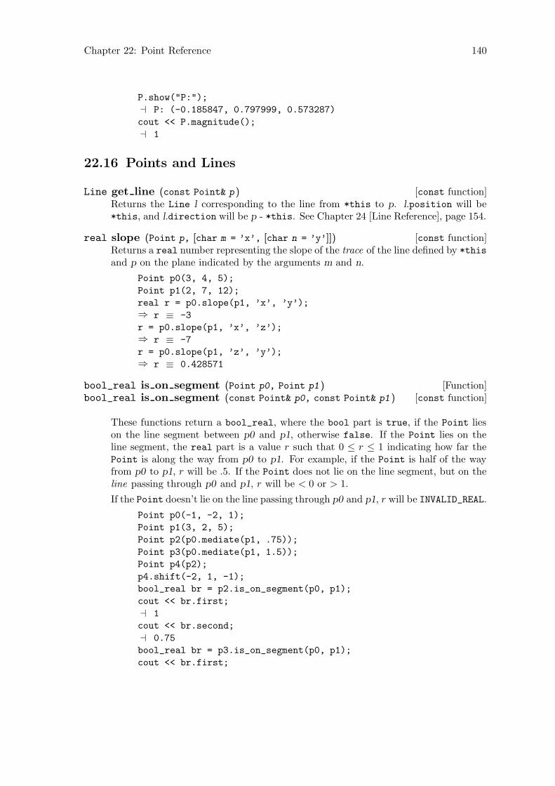
Chapter 22: Point Reference 140
P.show("P:");
a P: (-0.185847, 0.797999, 0.573287)
cout << P.magnitude();
a 1
22.16 Points and Lines
[const function]Line get line (const Point& p )Returns the Line l corresponding to the line from *this to p. l.position will be*this, and l.direction will be p - *this. See Chapter 24 [Line Reference], page 154.
[const function]real slope (Point p, [char m = ’x’, [char n = ’y’]])Returns a real number representing the slope of the trace of the line defined by *this
and p on the plane indicated by the arguments m and n.
Point p0(3, 4, 5);
Point p1(2, 7, 12);
real r = p0.slope(p1, ’x’, ’y’);⇒ r ≡ -3
r = p0.slope(p1, ’x’, ’z’);⇒ r ≡ -7
r = p0.slope(p1, ’z’, ’y’);⇒ r ≡ 0.428571
[Function]bool_real is on segment (Point p0, Point p1 )[const function]bool_real is on segment (const Point& p0, const Point& p1 )
These functions return a bool_real, where the bool part is true, if the Point lieson the line segment between p0 and p1, otherwise false. If the Point lies on theline segment, the real part is a value r such that 0 ≤ r ≤ 1 indicating how far thePoint is along the way from p0 to p1. For example, if the Point is half of the wayfrom p0 to p1, r will be .5. If the Point does not lie on the line segment, but on theline passing through p0 and p1, r will be < 0 or > 1.
If the Point doesn’t lie on the line passing through p0 and p1, r will be INVALID_REAL.
Point p0(-1, -2, 1);
Point p1(3, 2, 5);
Point p2(p0.mediate(p1, .75));
Point p3(p0.mediate(p1, 1.5));
Point p4(p2);
p4.shift(-2, 1, -1);
bool_real br = p2.is_on_segment(p0, p1);
cout << br.first;
a 1
cout << br.second;
a 0.75
bool_real br = p3.is_on_segment(p0, p1);
cout << br.first;

Chapter 22: Point Reference 141
a 0
cout << br.second;
a 1.5
bool_real br = p4.is_on_segment(p0, p1);
cout << br.first;
a 0
cout << br.second;
a 3.40282e+38
cout << (br.second == INVALID_REAL)
a 1
p0
p1
p2
p3
p4
Figure 91.
[const function]bool_real is on line (const Point& p0, const Point& p1 )Returns a bool_real where the bool part is true, if the Point lies on the line passingthrough p0 and p1, otherwise false. If the Point lies on the line, the real part is avalue r indicating how how far the Point is along the way from p0 to p1, otherwiseINVALID_REAL. The following values of r are possible for a call to P.is_on_line(A,
B), where the Point P lies on the line−−→AB:
P ≡ A =⇒ r ≡ 0.
P ≡ B =⇒ r ≡ 1.
P lies on the opposite side of A from B =⇒ r < 0.
P lies between A and B =⇒ 0 < r < 1.
P lies on the opposite side of A from B =⇒ r > 1
Point A(-1, -2);
Point B(2, 3);
Point C(B.mediate(A, 1.25));
bool_real br = C.is_on_line(A, B);
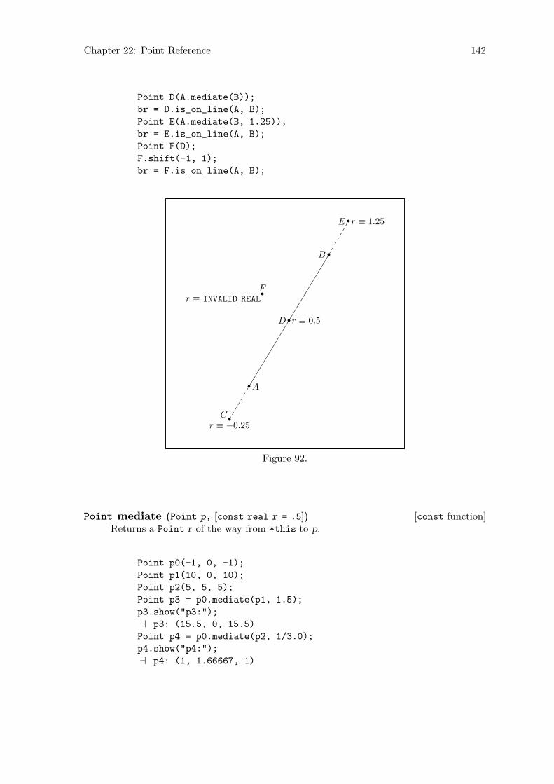
Chapter 22: Point Reference 142
Point D(A.mediate(B));
br = D.is_on_line(A, B);
Point E(A.mediate(B, 1.25));
br = E.is_on_line(A, B);
Point F(D);
F.shift(-1, 1);
br = F.is_on_line(A, B);
A
B
Cr ≡ −0.25
D r ≡ 0.5
E r ≡ 1.25
Fr ≡ INVALID REAL
Figure 92.
[const function]Point mediate (Point p, [const real r = .5])Returns a Point r of the way from *this to p.
Point p0(-1, 0, -1);
Point p1(10, 0, 10);
Point p2(5, 5, 5);
Point p3 = p0.mediate(p1, 1.5);
p3.show("p3:");
a p3: (15.5, 0, 15.5)
Point p4 = p0.mediate(p2, 1/3.0);
p4.show("p4:");
a p4: (1, 1.66667, 1)
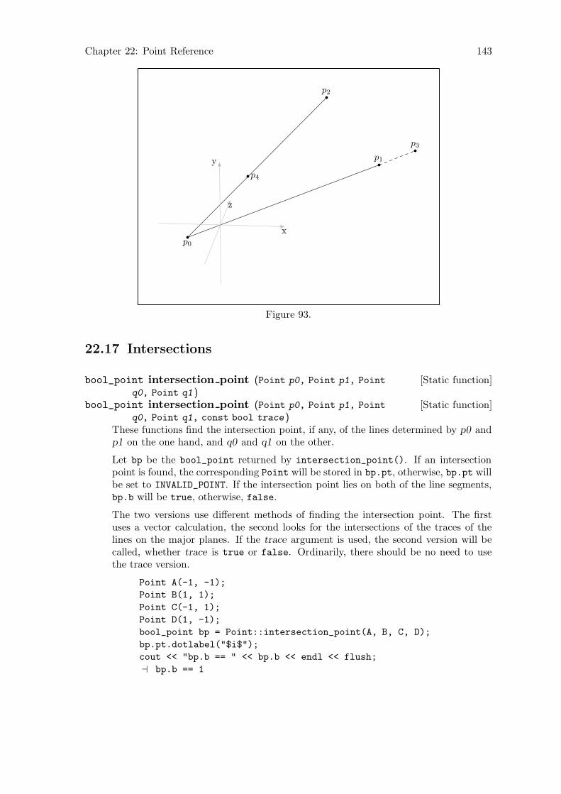
Chapter 22: Point Reference 143
p0
p1
p2
p3
p4
x
y
z
Figure 93.
22.17 Intersections
[Static function]bool_point intersection point (Point p0, Point p1, Point
q0, Point q1 )[Static function]bool_point intersection point (Point p0, Point p1, Point
q0, Point q1, const bool trace )These functions find the intersection point, if any, of the lines determined by p0 andp1 on the one hand, and q0 and q1 on the other.
Let bp be the bool_point returned by intersection_point(). If an intersectionpoint is found, the corresponding Point will be stored in bp.pt, otherwise, bp.pt willbe set to INVALID_POINT. If the intersection point lies on both of the line segments,bp.b will be true, otherwise, false.
The two versions use different methods of finding the intersection point. The firstuses a vector calculation, the second looks for the intersections of the traces of thelines on the major planes. If the trace argument is used, the second version will becalled, whether trace is true or false. Ordinarily, there should be no need to usethe trace version.
Point A(-1, -1);
Point B(1, 1);
Point C(-1, 1);
Point D(1, -1);
bool_point bp = Point::intersection_point(A, B, C, D);
bp.pt.dotlabel("$i$");
cout << "bp.b == " << bp.b << endl << flush;
a bp.b == 1
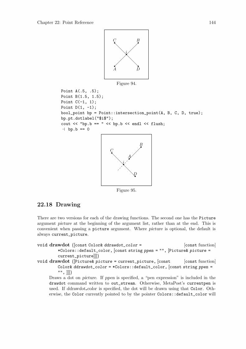
Chapter 22: Point Reference 144
A
BC
D
i
Figure 94.
Point A(.5, .5);
Point B(1.5, 1.5);
Point C(-1, 1);
Point D(1, -1);
bool_point bp = Point::intersection_point(A, B, C, D, true);
bp.pt.dotlabel("$i$");
cout << "bp.b == " << bp.b << endl << flush;
a bp.b == 0
A
B
C
D
i
Figure 95.
22.18 Drawing
There are two versions for each of the drawing functions. The second one has the Picture
argument picture at the beginning of the argument list, rather than at the end. This isconvenient when passing a picture argument. Where picture is optional, the default isalways current_picture.
[const function]void drawdot ([const Color& ddrawdot_color =
*Colors::default_color, [const string ppen = "", [Picture& picture =
current_picture]]])[const function]void drawdot ([Picture& picture = current_picture, [const
Color& ddrawdot_color = *Colors::default_color, [const string ppen =
"", ]]])Draws a dot on picture. If ppen is specified, a “pen expression” is included in thedrawdot command written to out_stream. Otherwise, MetaPost’s currentpen isused. If ddrawdot color is specified, the dot will be drawn using that Color. Oth-erwise, the Color currently pointed to by the pointer Colors::default_color will
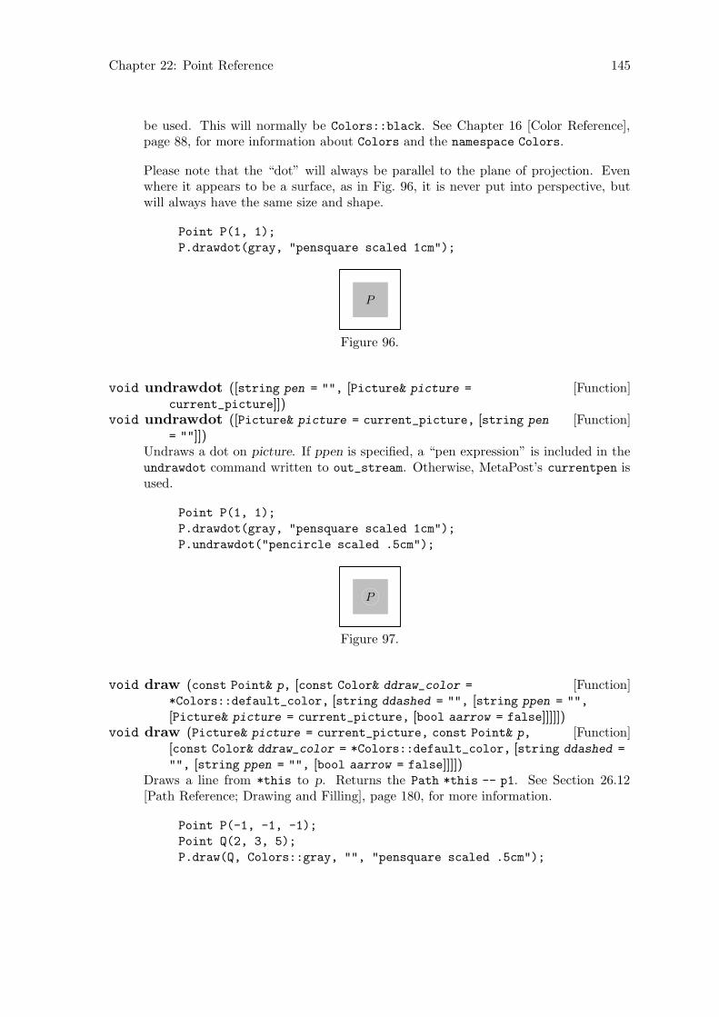
Chapter 22: Point Reference 145
be used. This will normally be Colors::black. See Chapter 16 [Color Reference],page 88, for more information about Colors and the namespace Colors.
Please note that the “dot” will always be parallel to the plane of projection. Evenwhere it appears to be a surface, as in Fig. 96, it is never put into perspective, butwill always have the same size and shape.
Point P(1, 1);
P.drawdot(gray, "pensquare scaled 1cm");
P
Figure 96.
[Function]void undrawdot ([string pen = "", [Picture& picture =
current_picture]])[Function]void undrawdot ([Picture& picture = current_picture, [string pen
= ""]])Undraws a dot on picture. If ppen is specified, a “pen expression” is included in theundrawdot command written to out_stream. Otherwise, MetaPost’s currentpen isused.
Point P(1, 1);
P.drawdot(gray, "pensquare scaled 1cm");
P.undrawdot("pencircle scaled .5cm");
P
Figure 97.
[Function]void draw (const Point& p, [const Color& ddraw_color =
*Colors::default_color, [string ddashed = "", [string ppen = "",
[Picture& picture = current_picture, [bool aarrow = false]]]]])[Function]void draw (Picture& picture = current_picture, const Point& p,
[const Color& ddraw_color = *Colors::default_color, [string ddashed =
"", [string ppen = "", [bool aarrow = false]]]])Draws a line from *this to p. Returns the Path *this -- p1. See Section 26.12[Path Reference; Drawing and Filling], page 180, for more information.
Point P(-1, -1, -1);
Point Q(2, 3, 5);
P.draw(Q, Colors::gray, "", "pensquare scaled .5cm");
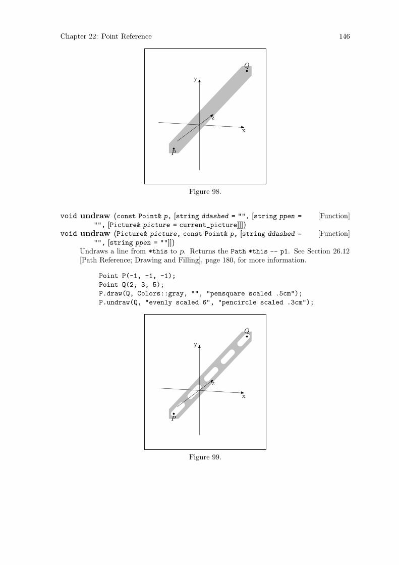
Chapter 22: Point Reference 146
P
Q
x
y
z
Figure 98.
[Function]void undraw (const Point& p, [string ddashed = "", [string ppen =
"", [Picture& picture = current_picture]]])[Function]void undraw (Picture& picture, const Point& p, [string ddashed =
"", [string ppen = ""]])Undraws a line from *this to p. Returns the Path *this -- p1. See Section 26.12[Path Reference; Drawing and Filling], page 180, for more information.
Point P(-1, -1, -1);
Point Q(2, 3, 5);
P.draw(Q, Colors::gray, "", "pensquare scaled .5cm");
P.undraw(Q, "evenly scaled 6", "pencircle scaled .3cm");
P
Q
x
y
z
Figure 99.
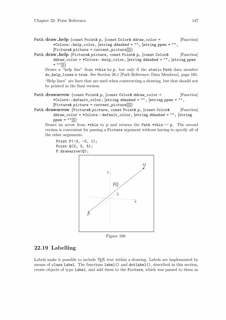
Chapter 22: Point Reference 147
[Function]Path draw help (const Point& p, [const Color& ddraw_color =
*Colors::help_color, [string ddashed = "", [string ppen = "",
[Picture& picture = current_picture]]]])[Function]Path draw help (Picture& picture, const Point& p, [const Color&
ddraw_color = *Colors::help_color, [string ddashed = "", [string ppen
= ""]]])Draws a “help line” from *this to p , but only if the static Path data memberdo_help_lines is true. See Section 26.1 [Path Reference; Data Members], page 165.
“Help lines” are lines that are used when constructing a drawing, but that should notbe printed in the final version.
[Function]Path drawarrow (const Point& p, [const Color& ddraw_color =
*Colors::default_color, [string ddashed = "", [string ppen = "",
[Picture& picture = current_picture]]]])[Function]Path drawarrow (Picture& picture, const Point& p, [const Color&
ddraw_color = *Colors::default_color, [string ddashed = "", [stringppen = ""]]])
Draws an arrow from *this to p and returns the Path *this -- p. The secondversion is convenient for passing a Picture argument without having to specify all ofthe other arguments.
Point P(-3, -2, 1);
Point Q(3, 3, 5);
P.drawarrow(Q);
P
Q
−−→PQ
x
y
z
Figure 100.
22.19 Labelling
Labels make it possible to include TEX text within a drawing. Labels are implemented bymeans of class Label. The functions label() and dotlabel(), described in this section,create objects of type Label, and add them to the Picture, which was passed to them as
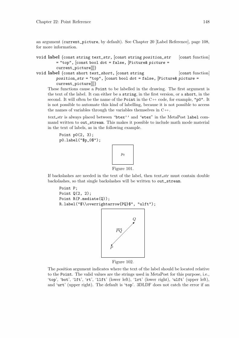
Chapter 22: Point Reference 148
an argument (current_picture, by default). See Chapter 20 [Label Reference], page 108,for more information.
[const function]void label (const string text_str, [const string position_str
= "top", [const bool dot = false, [Picture& picture =
current_picture]]])[const function]void label (const short text_short, [const string
position_str = "top", [const bool dot = false, [Picture& picture =
current_picture]]])These functions cause a Point to be labelled in the drawing. The first argument isthe text of the label. It can either be a string, in the first version, or a short, in thesecond. It will often be the name of the Point in the C++ code, for example, "p0". Itis not possible to automate this kind of labelling, because it is not possible to accessthe names of variables through the variables themselves in C++.
text str is always placed between “btex’’ and “etex” in the MetaPost label com-mand written to out_stream. This makes it possible to include math mode materialin the text of labels, as in the following example.
Point p0(2, 3);
p0.label("$p_0$");
p0
Figure 101.
If backslashes are needed in the text of the label, then text str must contain doublebackslashes, so that single backslashes will be written to out_stream.
Point P;
Point Q(2, 2);
Point R(P.mediate(Q));
R.label("$\\overrightarrow{PQ}$", "ulft");
P
Q
−−→PQ
Figure 102.
The position argument indicates where the text of the label should be located relativeto the Point. The valid values are the strings used in MetaPost for this purpose, i.e.,‘top’, ‘bot’, ‘lft’, ‘rt’, ‘llft’ (lower left), ‘lrt’ (lower right), ‘ulft’ (upper left),and ‘urt’ (upper right). The default is ‘top’. 3DLDF does not catch the error if an

Chapter 22: Point Reference 149
invalid position argument is used; the string is written to the output file and anerror will occur when MetaPost is run.
The dot argument is used to determine whether the label should be dotted or not.The default is false. The function dotlabel() calls label(), passing true as thelatter’s dot argument.
[const function]void dotlabel ([const string text_str, [const string
position_str = "top", [Picture& picture = current_picture]]])[const function]void dotlabel (const short text_short, [const string
position_str = "top", [Picture& picture = current_picture]])These functions are like label() except that they always produces a dot.
Point p0(2, 3);
p0.dotlabel("$p_0$");
p0
Figure 103.
22.20 Showing
[const function]void show ([string text = "", [char coords = ’w’, [const bool
do_persp = true, [const bool do_apply = true, [Focus* f = 0, [constunsigned short proj = Projections::persp, [const real factor = 1]]]]]]])
Prints text followed by the values of a set of coordinates to standard output (stdout).The other arguments are similar to those used in the functions described in Sec-tion 22.9 [Returning Coordinates], page 127.
Point P(1, 3, 5);
P.rotate(15, 67, 98);
P.show("P:");
a P: (-3.68621, -3.89112, 2.50421)
[Function]void show transform ([string text = ""])Prints text to standard output (stdout), or "transform:", if text is the emptystring (the default), and then calls transform.show().
Point A(-1, 1, 1);
Point B(13, 12, 6);
Point Q(31, 17.31, 6);
Q.rotate(A, B, 32);
Q.show_transform("Q.transform:");
a Q.transform:
Transform:
0.935 0.212 -0.284 0
-0.0749 0.902 0.426 0
0.346 -0.377 0.859 0
-0.336 0.687 -0.569 1

Chapter 22: Point Reference 150
22.21 Outputting
[Non-member function]ostream& operator<< (ostream& o, Point& p )Used in Path::output() for writing the x and y values of the projective_
coordinates of Points to out_stream. See Section 26.16 [Path Reference;Outputting], page 197. This is a low-level function that ordinary users should neverhave to invoke directly.
[Function]void output (void)Writes the MetaPost code for drawing or undrawing a Point to out_stream. Calledby Picture::output(), when a Shape on the Picture is a Point. See Section 21.8[Picture Reference; Outputting], page 114.
[Virtual function]void suppress output (void)Sets do_output to false, which causes a Point not to be output. This function iscalled in Picture::output(), when a Point cannot be projected. See Section 21.8[Picture Reference; Outputting], page 114.
[Virtual function]virtual void unsuppress_output (void)Resets do_output to true, so that a Point can potentially be output, ifPicture::output() is called again for the Picture the Point is on. This functionis called in Picture::output(). See Section 21.8 [Picture Reference; Outputting],page 114.
[Function]vector<shape*> extract (const Focus& f, const unsigned short
proj, real factor )Attempts to project the Point using the arguments passed to Picture::output(),which calls this function. If extract() succeeds, it returns a vector<shape*> con-taining only the Point. Otherwise, it returns an empty vector<shape*>.
[Virtual function]bool set extremes (void)Sets “extreme” values for x, y, and z in projective_coordinates. This is, of course,trivial for Points, because they only have one x, y and z-coordinate. So the maximaand minima for each coordinate are always the same.
[Virtual inline const function]valarray <real> get extremes (void)Returns projective_extremes.
[Virtual const function]real get minimum z (void)[Virtual const function]real get maximum z (void)[Virtual const function]real get mean z (void)
These functions return the minimum, maximum, and mean z-value of the Point.get_minimum_z() returns projective_extremes[4], get_maximum_z() returnsprojective_extremes[5], and get_mean_z() returns (projective_extremes[4]
+ projective_extremes[5]) / 2. However, since a Point has only one z-coordinate(from world_coordinates), these values will all be the same.
These functions are pure virtual functions in Shape, and are called on Points throughpointers to Shape. Therefore, they must be consistent with the versions for other typesderived from Shape. See Section 18.10 [Outputting Shapes], page 95.
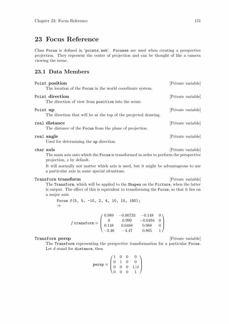
Chapter 23: Focus Reference 151
23 Focus Reference
Class Focus is defined in ‘points.web’. Focuses are used when creating a perspectiveprojection. They represent the center of projection and can be thought of like a cameraviewing the scene.
23.1 Data Members
[Private variable]Point positionThe location of the Focus in the world coordinate system.
[Private variable]Point directionThe direction of view from position into the scene.
[Private variable]Point upThe direction that will be at the top of the projected drawing.
[Private variable]real distanceThe distance of the Focus from the plane of projection.
[Private variable]real angleUsed for determining the up direction.
[Private variable]char axisThe main axis onto which the Focus is transformed in order to perform the perspectiveprojection, z by default.
It will normally not matter which axis is used, but it might be advantageous to usea particular axis in some special situations.
[Private variable]Transform transformThe Transform, which will be applied to the Shapes on the Picture, when the latteris output. The effect of this is equivalent to transforming the Focus, so that it lies ona major axis.
Focus f(5, 5, -10, 2, 4, 10, 10, 180);⇒
f.transform ≡
0.989 −0.00733 −0.148 00 0.999 −0.0494 0
0.148 0.0488 0.988 0−3.46 −4.47 0.865 1
[Private variable]Transform perspThe Transform representing the perspective transformation for a particular Focus.Let d stand for distance, then
persp ≡
1 0 0 00 1 0 00 0 0 1/d0 0 0 1

Chapter 23: Focus Reference 152
23.2 Global Variables
[Variable]Focus default focusEffectively, the default Focus in Picture::output(). See Section 21.8.2 [PictureReference; Outputting; Functions], page 115. It’s not really the default, but theversion of output() that doesn’t take a Focus argument calls another version thatdoes take one, passing default_focus to the latter as its Focus argument.
It’s necessary to do this in such a roundabout way, because Picture::output() mustbe declared before class Focus is completely defined and default_focus is declared.
The declaration ‘Focus& f = default_focus;’ makes f a reference to default_
focus, i.e., it makes f another name for default_focus. This may be convenient, ifyou don’t feel like typing default_focus.
23.3 Constructors and Setting Functions
[Default constructor]void Focus (void)Creates an empty Focus
[Constructor]void Focus (const real pos_x, const real pos_y, const real
pos_z, const real dir_x, const real dir_y, const real dir_z, const
real dist, [const real ang = 0, [char ax = ’z’]])Constructs a Focus using the first three real arguments as the x, y, and z-coordinatesof position, and the fourth through the sixth argument as the x, y, and z-coordinatesof direction. dist specifies the distance of the Focus from the plane of projection,ang the angle of rotation, which affects which direction is considered to be “up”, andax the major axis to which the Focus is aligned.
[Setting function]void set (const real pos_x, const real pos_y, const real
pos_z, const real dir_x, const real dir_y, const real dir_z, const
real dist, [const real ang = 0, [char ax = ’z’]])Resets an existing Focus. Corresponds to the constructor above.
[Constructor]void Focus (const Point& pos, const Point& dir, const real
dist, [const real ang = 0, [char ax = ’z’]])Constructs a Focus using Point arguments for position and direction. Otherwise,the arguments of this constructor correspond to those of the one above.
[Setting function]void set (const Point& pos, const Point& dir, const real
dist, [const real ang = 0, [char ax = ’z’]])Resets an existing Focus. Corresponds to the constructor above.
23.4 Operators
[Assignment operator]const Focus& operator= (const Focus& f )Sets the Focus to f.

Chapter 23: Focus Reference 153
23.5 Modifying
[Function]void reset angle (const real ang )Resets the value of angle and recalculates the Transforms transform and persp.
23.6 Querying
[Inline const function]const Point& get position (void)Returns position.
[Inline const function]const Point& get direction (void)Returns direction.
[Inline const function]const real& get distance (void)Returns distance.
[Inline const function]const Point& get up (void)Returns up.
[Inline const function]const Transform& get transform (void)Returns transform.
[Inline const function]const real& get transform element (const unsigned
int row, const unsigned int column )Returns an element of transform, given two unsigned ints for the row and thecolumn.
[Inline const function]const Transform& get persp (void)Returns persp.
[Inline const function]const real& get persp element (const unsigned int
row, const unsigned int column )Returns an element of persp, given two unsigned ints for the row and the column.
23.7 Showing
[const function]void show ([const string text_str = "Focus:", [const bool
show_transforms = false]])Prints text str to standard output (stdout), then calls Point::show() on position,direction, and up. Then the values of distance, axis, and angle are printed tostdout. If show transforms is true, transform and persp are shown as well.

Chapter 24: Line Reference 154
24 Line Reference
The struct Line is defined in ‘lines.web’. Lines are not Shapes. They are used forperforming vector operations. A Line is defined by a Point representing a position vectorand a Point representing a direction vector.
See also the descriptions of Point::get_line() in Section 22.16 [Points and Lines],page 140, and Path::get_line() in Section 26.15 [Path Reference; Querying], page 194.
24.1 Data Members
[Public variable]Point positionRepresents the position vector of the Line.
[Public variable]Point directionRepresents the direction vector of the Line.
24.2 Global Constants
[Constant]const Line INVALID LINEposition and direction are both INVALID_POINT.
24.3 Constructors
[Default constructor]void Line (const Point& pos = origin, const Point& dir =
origin)Creates a Line, setting position to pos, and direction to dir. If this function iscalled with no arguments, it creates a Line at the origin with no direction.
Point p(2, 1, 2);
Point d(-3, 3, 3.5);
Line L0(p, d);
Line L1 = p.get_line(d);
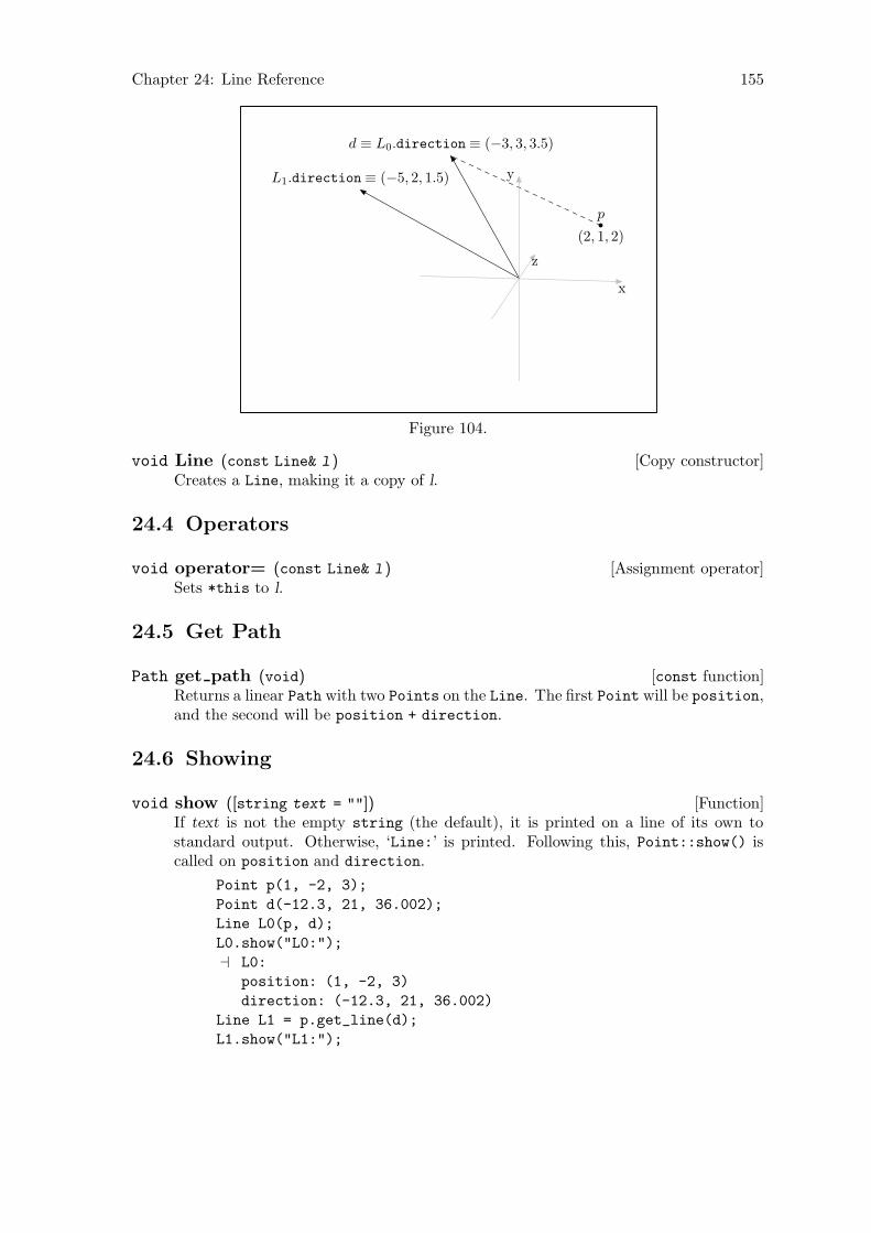
Chapter 24: Line Reference 155
x
y
z
p
(2, 1, 2)
d ≡ L0.direction ≡ (−3, 3, 3.5)
L1.direction ≡ (−5, 2, 1.5)
Figure 104.
[Copy constructor]void Line (const Line& l )Creates a Line, making it a copy of l.
24.4 Operators
[Assignment operator]void operator= (const Line& l )Sets *this to l.
24.5 Get Path
[const function]Path get path (void)Returns a linear Path with two Points on the Line. The first Point will be position,and the second will be position + direction.
24.6 Showing
[Function]void show ([string text = ""])If text is not the empty string (the default), it is printed on a line of its own tostandard output. Otherwise, ‘Line:’ is printed. Following this, Point::show() iscalled on position and direction.
Point p(1, -2, 3);
Point d(-12.3, 21, 36.002);
Line L0(p, d);
L0.show("L0:");
a L0:
position: (1, -2, 3)
direction: (-12.3, 21, 36.002)
Line L1 = p.get_line(d);
L1.show("L1:");

Chapter 24: Line Reference 156
a L1:
position: (1, -2, 3)
direction: (-13.3, 23, 33.002)
Path q = L1.get_path();
q.show("q:");
a q:
fill_draw_value == 0
(1, -2, 3) -- (-12.3, 21, 36.002);
Chapter 25: Plane Reference 157
25 Plane Reference
The struct Plane is defined in ‘planes.web’. Planes are not Shapes. They are used forperforming vector operations. A Plane is defined by a Point representing a point on theplane, a Point representing the normal to the plane, and the distance of the plane from theorigin.
The most common use of Planes is to represent the plane in which an existing planefigure lies. Therefore, they most likely to be created by using Path::get_plane(). SeeSection 26.15 [Path Reference; Querying], page 194. However, class Plane does haveconstructors for creating Planes directly, if desired. See Section 25.3 [Planes Reference;Constructors], page 157.
25.1 Data Members
Because the main purpose of Plane is to provide information about Shapes, its data mem-bers are all public.
[Public variable]Point pointRepresents a point on the plane.
[Public variable]Point normalRepresents the normal to the plane.
[Public variable]real distanceThe distance of the plane from the origin.
25.2 Global Constants
[Constant]const Plane INVALID PLANEA Plane with point ≡ normal, and distance ≡ INVALID_REAL.
INVALID_PLANE is returned from Path::get_plane(), if the Path is not planar. SeeSection 26.15 [Path Reference; Querying], page 194.
25.3 Constructors
[Default constructor]void Plane (void)Creates a degenerate Plane with point ≡ normal ≡ origin, and distance ≡ 0.
Planes constructed using this constructor will probably be set using the assignmentoperator or Path::get_plane() immediately, or very soon after being declared. SeeSection 25.4 [Planes Reference; Operators], page 158, and Section 26.15 [Paths Ref-erence; Querying], page 194.
[Copy constructor]void Plane (const Plane& p)Creates a new Plane, making it a copy of p.
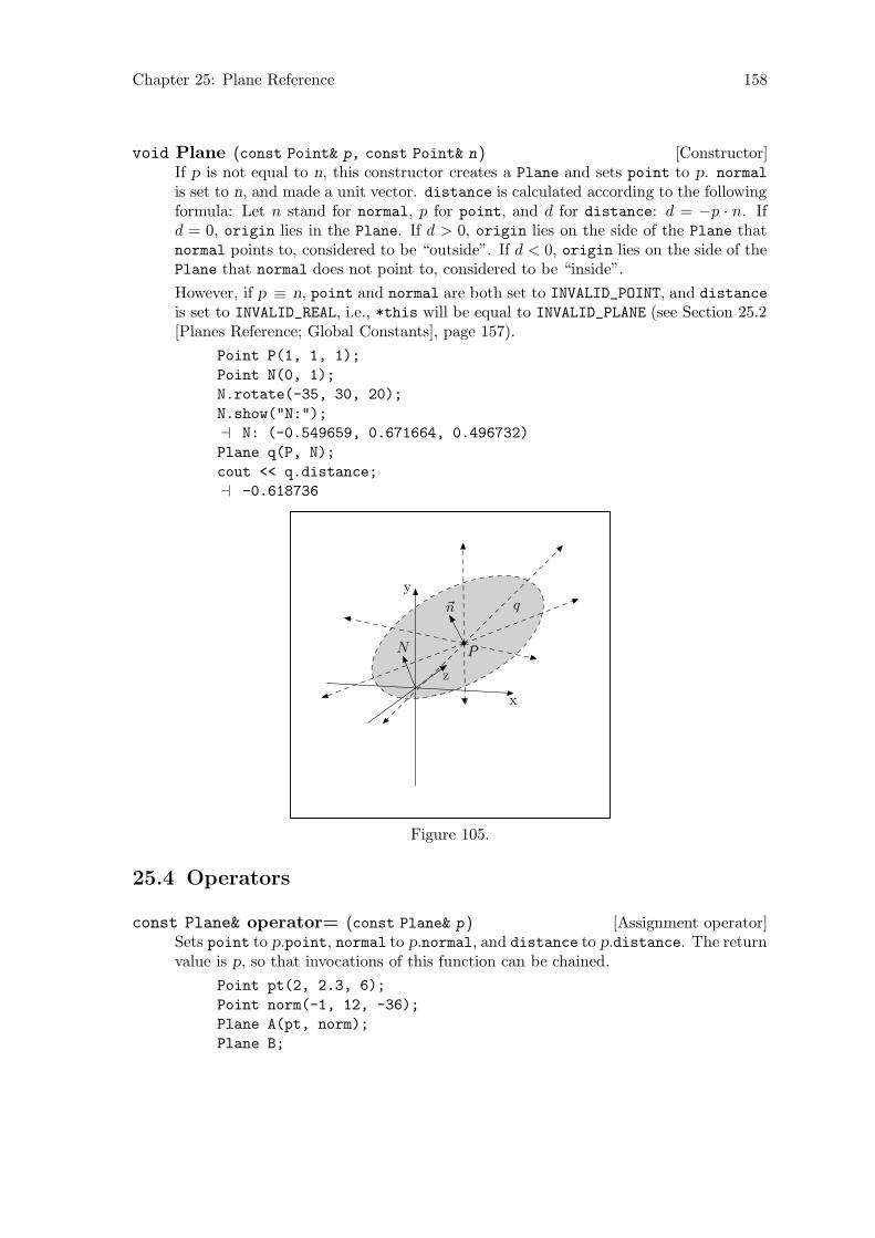
Chapter 25: Plane Reference 158
[Constructor]void Plane (const Point& p, const Point& n )If p is not equal to n, this constructor creates a Plane and sets point to p. normal
is set to n, and made a unit vector. distance is calculated according to the followingformula: Let n stand for normal, p for point, and d for distance: d = −p · n. Ifd = 0, origin lies in the Plane. If d > 0, origin lies on the side of the Plane thatnormal points to, considered to be “outside”. If d < 0, origin lies on the side of thePlane that normal does not point to, considered to be “inside”.
However, if p ≡ n, point and normal are both set to INVALID_POINT, and distance
is set to INVALID_REAL, i.e., *this will be equal to INVALID_PLANE (see Section 25.2[Planes Reference; Global Constants], page 157).
Point P(1, 1, 1);
Point N(0, 1);
N.rotate(-35, 30, 20);
N.show("N:");
a N: (-0.549659, 0.671664, 0.496732)
Plane q(P, N);
cout << q.distance;
a -0.618736
N P
~n q
x
y
z
Figure 105.
25.4 Operators
[Assignment operator]const Plane& operator= (const Plane& p )Sets point to p.point, normal to p.normal, and distance to p.distance. The returnvalue is p, so that invocations of this function can be chained.
Point pt(2, 2.3, 6);
Point norm(-1, 12, -36);
Plane A(pt, norm);
Plane B;

Chapter 25: Plane Reference 159
Plane C;
B = C = A;
A.show("A:");
a A:
normal: (-0.0263432, 0.316118, -0.948354)
point: (2, 2.3, 6)
distance == 5.01574
cout << (A == B && A == C && B == C);
a 1
[const operator]bool operator== (const Plane& p )Equality operator. Compares *this and p, and returns true, if point ≡ p.point,normal ≡ p.normal, and distance ≡ p.distance, otherwise false.
[const operator]bool operator!= (const Plane& p )Inequality operator. Compares *this and p and returns true, if point 6= p.point,or normal 6= p.normal, or distance 6= p.distance. Otherwise, it returns false.
25.5 Returning Information
[const function]real_short get distance (const Point& p )[const function]real_short get distance (void)
The version of this function taking a Point argument returns a real_short r, whosereal part (r.first) represents the distance of p from the Plane. This value is alwayspositive. r.second can take on three values:
0 If the Point lies in the Plane.
1 If it lies on the side of the Plane pointed at by the normal to the Plane,considered to be the “outside”.
-1 If it lies on the side of the Plane not pointed at by the normal to thePlane, considered to be the “inside”.
The version taking no argument returns the absolute of the data member distance
and its sign, i.e., the distance of origin to the Plane, and which side of the Plane itlies on.
It would have been possible to use origin as the default for an optional Point argu-ment, but I’ve chosen to overload this function, because of problems that may arise,when I implement user_coordinates and view_coordinates (see Section 22.1 [PointReference; Data Members], page 119).
Point N(0, 1);
N.rotate(-10, 20, 20);
Point P(1, 1, 1);
Plane q(P, N);
Point A(4, -2, 4);
Point B(-1, 3, 2);
Point C = q.intersection_point(A, B).pt;
real_short bp;
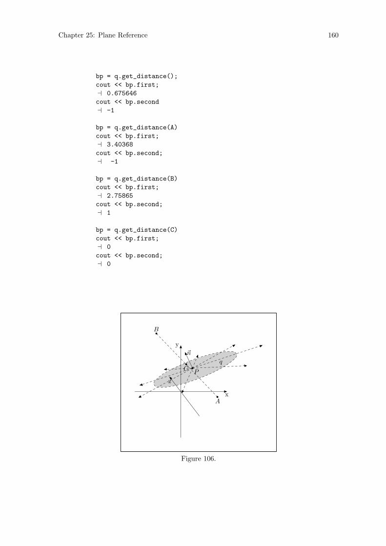
Chapter 25: Plane Reference 160
bp = q.get_distance();
cout << bp.first;
a 0.675646
cout << bp.second
a -1
bp = q.get_distance(A)
cout << bp.first;
a 3.40368
cout << bp.second;
a -1
bp = q.get_distance(B)
cout << bp.first;
a 2.75865
cout << bp.second;
a 1
bp = q.get_distance(C)
cout << bp.first;
a 0
cout << bp.second;
a 0
P
~n
q
A
B
C
x
y
z
Figure 106.
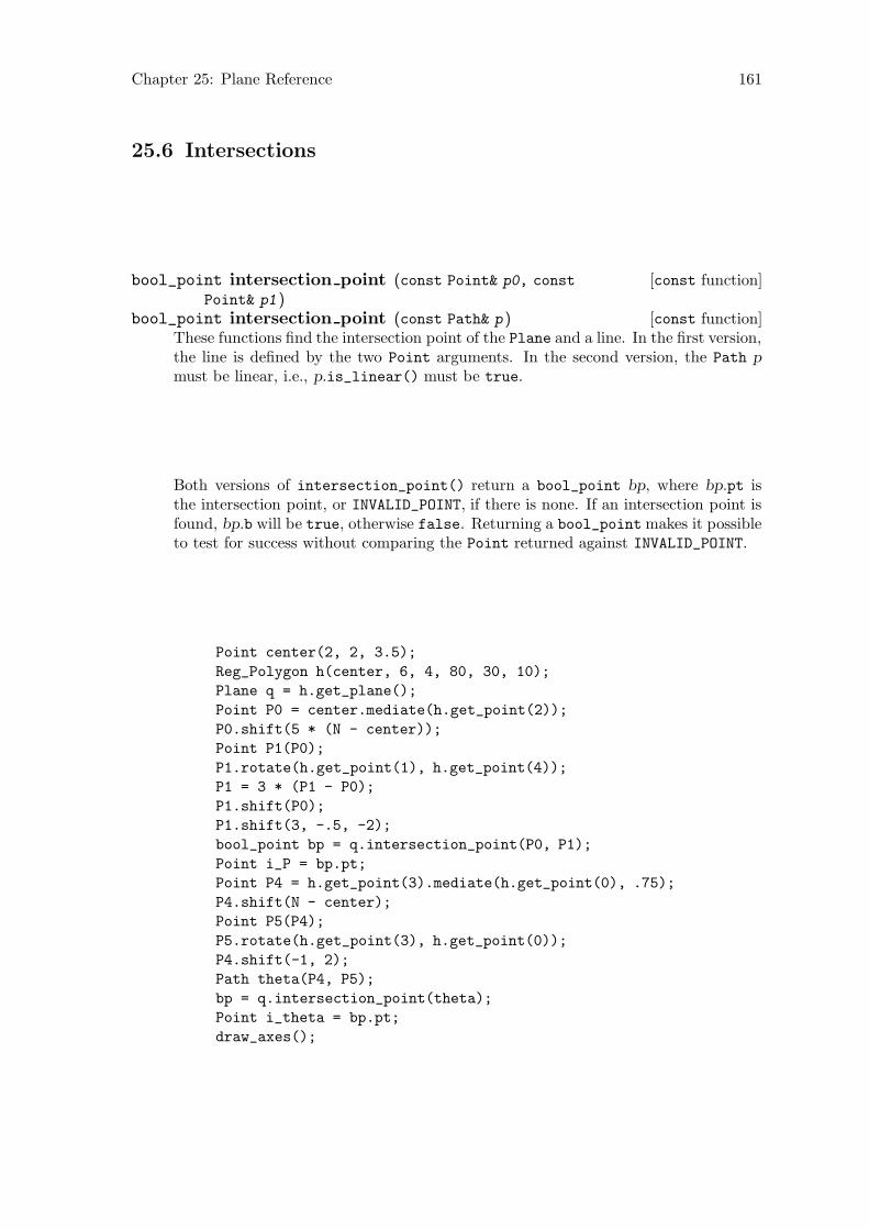
Chapter 25: Plane Reference 161
25.6 Intersections
[const function]bool_point intersection point (const Point& p0, const
Point& p1 )[const function]bool_point intersection point (const Path& p )
These functions find the intersection point of the Plane and a line. In the first version,the line is defined by the two Point arguments. In the second version, the Path p
must be linear, i.e., p.is_linear() must be true.
Both versions of intersection_point() return a bool_point bp, where bp.pt isthe intersection point, or INVALID_POINT, if there is none. If an intersection point isfound, bp.b will be true, otherwise false. Returning a bool_point makes it possibleto test for success without comparing the Point returned against INVALID_POINT.
Point center(2, 2, 3.5);
Reg_Polygon h(center, 6, 4, 80, 30, 10);
Plane q = h.get_plane();
Point P0 = center.mediate(h.get_point(2));
P0.shift(5 * (N - center));
Point P1(P0);
P1.rotate(h.get_point(1), h.get_point(4));
P1 = 3 * (P1 - P0);
P1.shift(P0);
P1.shift(3, -.5, -2);
bool_point bp = q.intersection_point(P0, P1);
Point i_P = bp.pt;
Point P4 = h.get_point(3).mediate(h.get_point(0), .75);
P4.shift(N - center);
Point P5(P4);
P5.rotate(h.get_point(3), h.get_point(0));
P4.shift(-1, 2);
Path theta(P4, P5);
bp = q.intersection_point(theta);
Point i_theta = bp.pt;
draw_axes();
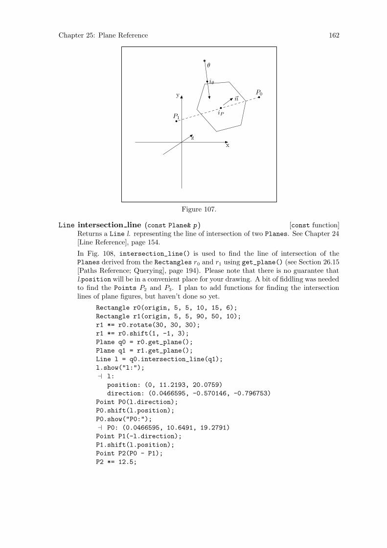
Chapter 25: Plane Reference 162
~nP0
P1
iP
θ
iθ
x
y
z
Figure 107.
[const function]Line intersection line (const Plane& p )Returns a Line l. representing the line of intersection of two Planes. See Chapter 24[Line Reference], page 154.
In Fig. 108, intersection_line() is used to find the line of intersection of thePlanes derived from the Rectangles r0 and r1 using get_plane() (see Section 26.15[Paths Reference; Querying], page 194). Please note that there is no guarantee thatl.position will be in a convenient place for your drawing. A bit of fiddling was neededto find the Points P2 and P3. I plan to add functions for finding the intersectionlines of plane figures, but haven’t done so yet.
Rectangle r0(origin, 5, 5, 10, 15, 6);
Rectangle r1(origin, 5, 5, 90, 50, 10);
r1 *= r0.rotate(30, 30, 30);
r1 *= r0.shift(1, -1, 3);
Plane q0 = r0.get_plane();
Plane q1 = r1.get_plane();
Line l = q0.intersection_line(q1);
l.show("l:");
a l:
position: (0, 11.2193, 20.0759)
direction: (0.0466595, -0.570146, -0.796753)
Point P0(l.direction);
P0.shift(l.position);
P0.show("P0:");
a P0: (0.0466595, 10.6491, 19.2791)
Point P1(-l.direction);
P1.shift(l.position);
Point P2(P0 - P1);
P2 *= 12.5;

Chapter 25: Plane Reference 163
P2.shift(P0);
cout << P2.is_on_plane(q0);
a 1
cout << P2.is_on_plane(q1);
a 1
Point P3(P0 - P1);
P3 *= 7;
P3.shift(P0);
cout << P3.is_on_plane(q0);
a 1
cout << P3.is_on_plane(q1);
a 1
r0
r1
P2
P3
l
x
y
z
Figure 108.
25.7 Showing
[const function]void show ([string text = ""])Prints information about the Plane to standard output. If text is not the emptystring, it is printed to the standard output. Otherwise, ‘Plane:’ is printed. Followingthis, if the Plane is equal to INVALID_PLANE (see Section 25.2 [Planes Reference;Global Constants], page 157), a message to this effect is printed to standard output.Otherwise, normal and point are shown using Point::show() (see Section 22.20[Point Reference; Showing], page 149). Finally, distance is printed.
Point A(1, 3, 2.5);
Rectangle r0(A, 5, 5, 10, 15, 6);
Plane p = r0.get_plane();
a p:
normal: (-0.0582432, 0.984111, -0.167731)

Chapter 25: Plane Reference 164
point: (-0.722481, 2.38245, -0.525176)
distance == -2.47476

Chapter 26: Path Reference 165
26 Path Reference
Class Path is defined in ‘paths.web’. It is derived from Shape using protected derivation.
26.1 Data Members
[Protected variable]bool line switchtrue if the Path was created using the constructor Path(const Point& p0, const
Point& p1), directly or indirectly. See Section 26.2 [Path Reference; Constructorsand Setting Functions], page 167.
Point p0;
Point p1(1, 1);
Point p2(2, 3);
Path q0(p0, p1);
cout << q0.get_line_switch();
a 1
Path q1;
q1 = q0;
cout << q1.get_line_switch();
a 1
Path q2 = p0.draw(p1);
cout << q2.get_line_switch();
a 1
Path q3("..", false, &p1, &p2, &p0, 0);
cout << q3.get_line_switch();
a 0
p0
p1
p2
q0 ≡ q1 ≡ q2
q3
Figure 109.
Some Path functions only work on linear Paths, so it’s necessary to be able to dis-tinguish them from non-linear ones. The function is_linear() should be enoughto ensure that all of these functions work, so I plan to make line_switch obsoletesoon. However, at the moment, it’s still needed. See Section 26.15 [Path Reference;Querying], page 194.

Chapter 26: Path Reference 166
[Protected variable]bool cycle switchtrue if the Path is cyclical, otherwise false.
[Protected variable]bool on free storetrue if the Path was dynamically allocated on the free store. Otherwise false. Setto true only in create_new<Path>(), which should be the only way Paths are everdynamically allocated. See Section 26.2 [Path Constructors and Setting Functions],page 167.
[Protected variable]bool do outputUsed in Picture::output(). Set to false if the Path isn’t projectable using thearguments passed to Picture::output(). See Section 21.8 [Picture Reference; Out-putting], page 114.
[Protected variable]signed short fill draw valueSet in the drawing and filling functions, and used in Path::output(), to determinewhat MetaPost code to write to out_stream. See Section 26.12 [Path Reference;Drawing and Filling], page 180, and Section 26.16 [Path Reference; Outputting],page 197.
[Protected variable]const Color* draw colorPointer to the Color used if the Path is drawn.
[Protected variable]const Color* fill colorPointer to the Color used if the Path is filled.
[Protected variable]string dashedString written to out_stream for the “dash pattern” in a MetaPost draw or undraw
command. If and only if dashed is not the empty string, “dashed <dash pattern>” iswritten to out_stream.
Dash patterns have no meaning inside 3DLDF; dashed, if non-empty, is written un-changed to out_stream. I may change this in the future.
[Protected variable]string penString written to out_stream for the pen to be used in a MetaPost draw, undraw,filldraw, or unfilldraw command. If and only if pen is not the empty string,“withpen <. . .>” is written to out_stream.
Pens have no meaning inside 3DLDF; pen, if non-empty, is written unchanged toout_stream. I may change this in the future.
[Protected variable]bool arrowIndicates whether an arrow should be drawn when outputting a Path. Set to true
on a Path created on the free store and put onto a Picture by drawarrow().
[Protected variable]valarray<real> projective extremesContains the maxima and minima of the x, y, and z-coordinates of the projections
of Points on a Path using a particular Focus. Set in set_extremes() and used inPicture::output() for surface hiding.
Chapter 26: Path Reference 167
[Protected variable]vector<Point*> pointsPointers to the Points on the Path.
[Protected variable]vector<string> connectorsThe connectors between the Points on the Path. Connectors are simply strings in3DLDF, they are written unchanged to out_stream.
[Public static variable]const Color* help colorPointer to a const Color, which becomes the default for draw_help(). See Sec-tion 26.12 [Path Reference; Drawing and Filling], page 180.
Please note that help_color is a pointer to a const Color, not a const pointer to aColor or a const pointer to a const Color! It’s easy to get confused by the syntaxfor these types of pointers.1
[Public static variable]string help dash patternThe default dash pattern for draw_help().
[Public static variable]bool do help linestrue if help lines should be output, otherwise false. If false, a call to draw_
help() does not cause a copy of the Path to be created and put onto a Picture. SeeSection 26.12 [Path Reference; Drawing and Filling], page 180.
26.2 Constructors and Setting Functions
[Default constructor]void Path (void)Creates an empty Path with no Points and no connectors.
[Constructor]void Path (const Point& p0, const Point& p1 )Creates a line (more precisely, a line segment) between p0 and p1. The single con-nector between the two Points is set to "--" and the data member line_switch
(of type bool) is set to true. There are certain operations on Paths that are onlyapplicable to lines, so it’s necessary to store the information that a Path is a line.2
Point A(-2, -2.5, -1);
Point B(3, 2, 2.5)
Path p(A, B);
p.show("p:");
a p:
(-2, -2.5, -1) -- (3, 2, 2.5);
1 Stroustrup, The C++ Programming Language, p. 96.2 It isn’t sufficient to check whether a Path consists of only two Points to determine whether it is a line or
not, since a connector with “curl” could cause it to be non-linear. On the other hand, Paths containingonly colinear Points and the connector "--" are perfectly legitimate lines. I’m in the process of changingall of the code that tests for linearity by checking the value of line_switch, so that it uses is_linear()instead. When I’ve done this, it may be possible to eliminate line_switch. See Section 26.1 [PathReference; Data Members], page 165, and Section 26.15 [Path Reference; Querying], page 194.
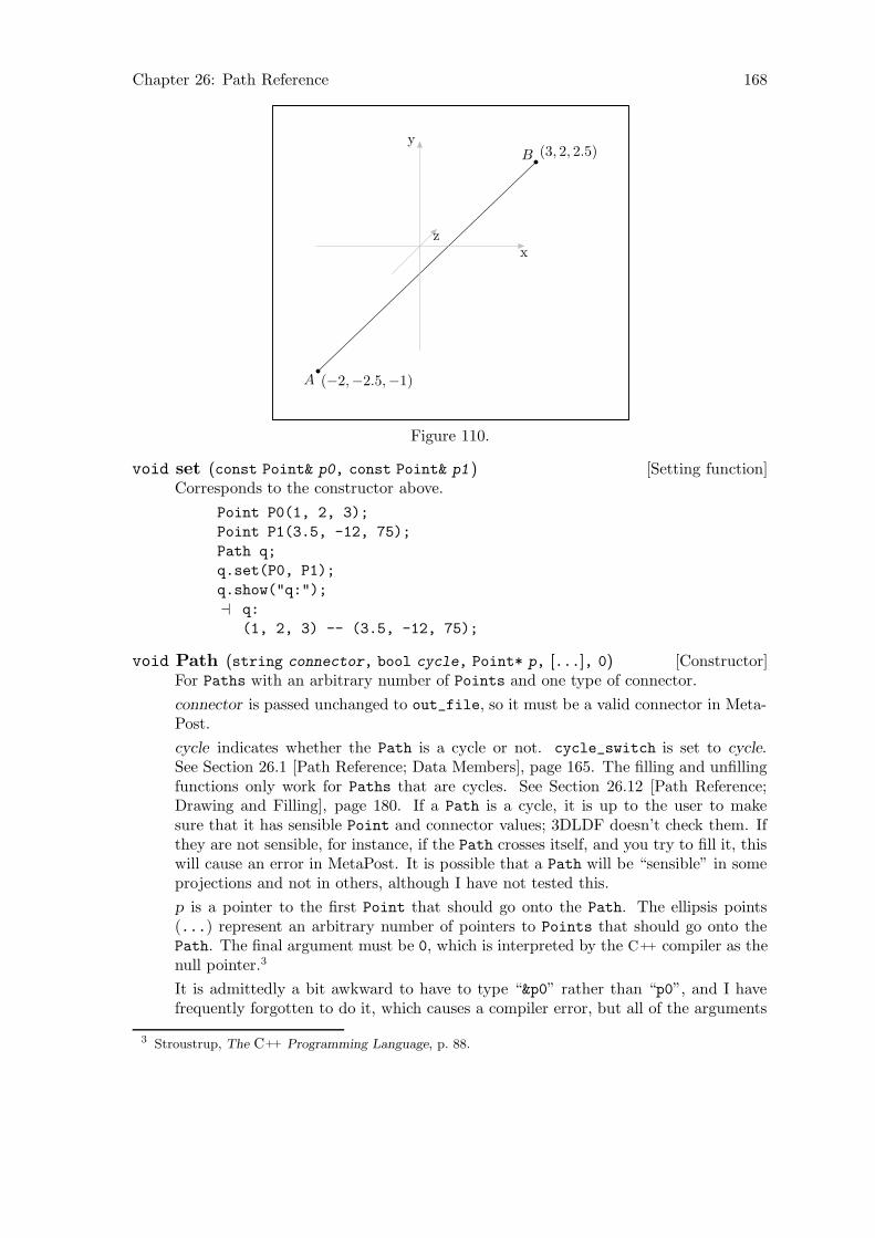
Chapter 26: Path Reference 168
A (−2,−2.5,−1)
B (3, 2, 2.5)
x
y
z
Figure 110.
[Setting function]void set (const Point& p0, const Point& p1 )Corresponds to the constructor above.
Point P0(1, 2, 3);
Point P1(3.5, -12, 75);
Path q;
q.set(P0, P1);
q.show("q:");
a q:
(1, 2, 3) -- (3.5, -12, 75);
[Constructor]void Path (string connector, bool cycle, Point* p, [...], 0)For Paths with an arbitrary number of Points and one type of connector.
connector is passed unchanged to out_file, so it must be a valid connector in Meta-Post.
cycle indicates whether the Path is a cycle or not. cycle_switch is set to cycle.See Section 26.1 [Path Reference; Data Members], page 165. The filling and unfillingfunctions only work for Paths that are cycles. See Section 26.12 [Path Reference;Drawing and Filling], page 180. If a Path is a cycle, it is up to the user to makesure that it has sensible Point and connector values; 3DLDF doesn’t check them. Ifthey are not sensible, for instance, if the Path crosses itself, and you try to fill it, thiswill cause an error in MetaPost. It is possible that a Path will be “sensible” in someprojections and not in others, although I have not tested this.
p is a pointer to the first Point that should go onto the Path. The ellipsis points(...) represent an arbitrary number of pointers to Points that should go onto thePath. The final argument must be 0, which is interpreted by the C++ compiler as thenull pointer.3
It is admittedly a bit awkward to have to type “&p0” rather than “p0”, and I havefrequently forgotten to do it, which causes a compiler error, but all of the arguments
3 Stroustrup, The C++ Programming Language, p. 88.
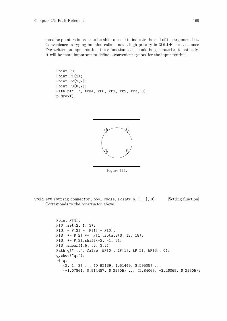
Chapter 26: Path Reference 169
must be pointers in order to be able to use 0 to indicate the end of the argument list.Convenience in typing function calls is not a high priority in 3DLDF, because onceI’ve written an input routine, these function calls should be generated automatically.It will be more important to define a convenient syntax for the input routine.
Point P0;
Point P1(2);
Point P2(2,2);
Point P3(0,2);
Path p("..", true, &P0, &P1, &P2, &P3, 0);
p.draw();
P0 P1
P2P3
Figure 111.
[Setting function]void set (string connector, bool cycle, Point* p, [...], 0)Corresponds to the constructor above.
Point P[4];
P[0].set(2, 1, 3);
P[3] = P[2] = P[1] = P[0];
P[3] *= P[2] *= P[1].rotate(3, 12, 18);
P[3] *= P[2].shift(-2, -1, 3);
P[3].shear(1.5, .5, 3.5);
Path q("...", false, &P[0], &P[1], &P[2], &P[3], 0);
q.show("q:");
a q:
(2, 1, 3) ... (0.92139, 1.51449, 3.29505) ...
(-1.07861, 0.514487, 6.29505) ... (2.84065, -3.26065, 6.29505);
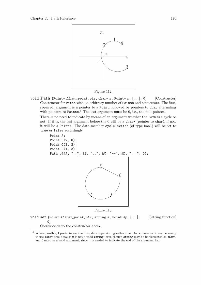
Chapter 26: Path Reference 170
01
2
3
x
y
z
Figure 112.
[Constructor]void Path (Point* first_point_ptr, char* s, Point* p, [...], 0)Constructor for Paths with an arbitrary number of Points and connectors. The first,required, argument is a pointer to a Point, followed by pointers to char alternatingwith pointers to Points.4 The last argument must be 0, i.e., the null pointer.
There is no need to indicate by means of an argument whether the Path is a cycle ornot: If it is, the last argument before the 0 will be a char* (pointer to char), if not,it will be a Point*. The data member cycle_switch (of type bool) will be set totrue or false accordingly.
Point A;
Point B(2, 0);
Point C(3, 2);
Point D(1, 3);
Path p(&A, "..", &B, "..", &C, "--", &D, "...", 0);
A B
C
D
Figure 113.
[Setting function]void set (Point *first_point_ptr, string s, Point *p, [...],0)
Corresponds to the constructor above.
4 Where possible, I prefer to use the C++ data type string rather than char*, however it was necessaryto use char* here because 0 is not a valid string, even though string may be implemented as char*,and 0 must be a valid argument, since it is needed to indicate the end of the argument list.
Chapter 26: Path Reference 171
[Copy constructor]void Path (const Path& p )Creates a new Path, making it a copy of p.
[Template specializations]Path* create new<Path> (const Path* p )Path* create new<Path> (const Path& p )
Pseudo-constructors for dynamic allocation of Paths. They create a Path on the freestore and allocate memory for it using new(Path). They return a pointer to the newPath.
If p is a non-zero pointer or a reference, the new Path will be a copy of p. Ifthe new object is not meant to be a copy of an existing one, ‘0’ must be passedto create_new<Path>() as its argument. See Chapter 14 [Dynamic Allocation ofShapes], page 84, for more information.
create_new<Path>() is used in the drawing and filling functions for copying a Path
and putting the copy onto a Picture. See Section 26.12 [Path Reference; Drawingand Filling], page 180.
26.3 Destructor
[virtual Destructor]void ~Path (void)All of the Points on a Path are created by create_new<Point>(), which allo-cates them dynamically on the free store. Therefore, the destructor calls delete()
on all of the pointers on points. Following this, it calls points.clear() andconnectors.clear(). draw_color and fill_color may or may not have been allo-cated on the free store, so ~Path() checks this first, and deletes them, if they were.Then, it sets them to 0.
26.4 Operators
[Virtual function]Transform operator*= (const Transform& t )Calls Point::operator*=(t) on each of the Points on the Path. See Section 22.6[Point Reference; Operators], page 124. This has the effect of transforming the entirePath by t. Please note that Path does not have a transform data member of its own.
[Function]void operator+= (const Point& pt )Copies pt and pushes a pointer to the copy onto points. The last connector in thePath will be used to connect the new Point and the previous one.
Point A(1, 2, 3);
Point B(3, 4, 5);
Path q;
q += A;
q += B;
q.show("q:");
a q:
(1, 2, 3) -- (3, 4, 5);
Chapter 26: Path Reference 172
[const function]Path operator+ (const Point& pt )Copies the Path and pt, and pushes a pointer to the copy of pt onto points in thenew Path. The last connector in the new Path will be used to connect the new Point
and the previous one. The Path remains unchanged.
[Function]void operator&= (const Path& pa )Concatenates two Paths. The result is assigned to *this. Neither *this nor pa maybe cyclical, i.e., cycle_switch must be false for both Paths.
[const function]Path operator& (const Path& pa )Returns a Path representing the concatenation of *this and pa. *this remainsunchanged. Neither *this nor pa may be cyclical, i.e., cycle_switch must be falsefor both Paths.
[Function]void operator+= (const string s )Pushes s onto connectors.
26.5 Appending
[Function]Path append (const Path& pa, [string connector = "--", [boolassign = true]])
Appends pa to *this using connector to join them and returns the resulting Path. Ifassign ≡ true, then the return value is assigned to *this, otherwise, *this remainsunchanged.
If necessary, a const version could be added, for const Paths.
Point A(-2, 2);
Point B(-2, -2);
Point C(2, -2);
Point D(2, 2);
Path q("--", false, &A, &B, &C, &D, 0);
Point E(1, 2);
Point F(0, 4);
Point G(-.5, 3);
Path r("..", false, &E, &F, &G, 0);
q.append(r, "..", true);
q += "..";
q += "--";
q.set_cycle();
q.show("q:");
a q:
(-2, 2, 0) -- (-2, -2, 0) --
(2, -2, 0) -- (2, 2, 0) ..
(1, 2, 0) .. (0, 4, 0) ..
(-0.5, 3, 0) -- cycle;

Chapter 26: Path Reference 173
A
B C
DE
F
G
Figure 114.
26.6 Copying
[const virtual function]Shape* get copy (void)Creates a copy of the Path using create_new<Path>(), which returns a pointer toPath. get_copy() then casts this pointer to a pointer to Shape and returns it.
This function is used when copying Pictures and in Solid::output(), where objectsof types derived from Shape must be handled in the same way, without their actualtypes being known.
26.7 Clearing
[Virtual function]void clear (void)Does the same thing the destructor ~Path() does: Calls delete() on the pointersto Points on points, clears points and connectors, deletes draw_color and fill_
color, if they point to Colors that were allocated on the free store, and sets themto 0.
clear() is a pure virtual function in class Shape, so Path must be have a clear()
function. It is needed, because it is sometimes called through a pointer to Shape, sothat ~Path() cannot be accessed. At least, so far I haven’t found a way to call adestructor through the virtual function facility.
26.8 Modifying
[Virtual function]bool set on free store ([bool b = true])Sets on_free_store to b. This is used in the template function create_new(). SeeSection 26.2 [Path Reference; Constructors and Setting Functions], page 167.
Chapter 26: Path Reference 174
[Virtual function]void set fill draw value (const signed short s )Sets fill_draw_value to s, which should be one of Shape::DRAW, Shape::FILL,Shape::FILLDRAW, Shape::UNDRAW, Shape::UNFILL, or Shape::UNFILLDRAW.
[Virtual function]void set draw color (const Color& c )[Virtual function]void set draw color (const Color * c )
Sets draw_color (a pointer to a const Color) to &c or c, depending on whether theversion with a reference argument or the version with a pointer argument is used.
set_draw_color() is used in the Solid drawing and filling functions, becausePath::draw_color is protected, and the Solid cannot access it directly. SeeSection 34.13 [Solid Reference; Drawing and Filling], page 255.
[Virtual function]void set fill color (const Color& c )[Virtual function]void set fill color (const Color* c )
Sets fill_color (a pointer to a const Color) to &c or c, depending on whether theversion with a reference argument or the version with a pointer argument is used.
set_fill_color() is used in the Solid drawing and filling functions, becausePath::fill_color is protected, and the Solid cannot access it directly. SeeSection 34.13 [Solid Reference; Drawing and Filling], page 255.
[Virtual function]void set dash pattern ([const string s = ""])Sets dashed to s.
[Virtual function]void set pen ([const string s = ""])Sets pen to s.
[Virtual function]void set connectors ([const string s = ".."])Clears connectors and then pushes s onto it, making s the only connector. Ad-ditional connectors can be added by using Path::operator+=(const string). SeeSection 26.4 [Path Reference; Operators], page 171.
I plan to add a version of this function taking a vector of strings as its argument,to make it possible to set several connectors at one time.
26.9 Affine Transformations
[Virtual function]Transform rotate (const real x, [const real y = 0, [constreal z = 0]])
Creates a Transform t locally and calls t.rotate(x, y, z). t is then applied to allof the Points on points. The return value is t.
[Function]Transform scale (real x, [real y = 1, [real z = 1 ]])Creates a Transform t locally and calls t.scale(x, y, z). t is then applied to allof the Points on points. The return value is t.
The Points on the Path are scaled according to the arguments:
Point pt[8];
pt[0] = (-1, -1);
for (int i = 1; i < 8; ++i)

Chapter 26: Path Reference 175
{
pt[i] = pt[0];
pt[i].rotate(0, 0, i * 45);
}
Path p("--", true, &pt[0], &pt[1], &pt[2], &pt[3],
&pt[4], &pt[5], &pt[6],
&pt[7], 0);
p.draw();
p.scale(2, 2);
p.draw();
(0, 0, 0)
Figure 115.
[Function]Transform shear (real xy, [real xz = 0, [real yx = 0, [real yz = 0,
[real zx = 0, [real zy = 0]]]]])Creates a Transform t locally and calls t.shear(xy, xz, yx, yz, zx, zy). t is thenapplied to all of the Points on points. The return value is t.
Point p0;
Point p1(1);
Point p2(1, 1);
Point p3(0, 1);
Path q("--", true, &p0, &p1, &p2, &p3, 0);
q.rotate(0, 45);
q.shift(1);
q.filldraw(black, light_gray);
q.shear(1.5, 2, 2.5, 3, 3.5, 5);
q.filldraw(black, light_gray);

Chapter 26: Path Reference 176
(1, 0, 0)
(1.70711, 0, 0.707107)
(1.70711, 1, 0.707107)(1, 1, 0)
(1, 2.5, 3.5)
(3.12132, 6.38909, 6.68198) (4.62132, 7.38909, 11.682)
(2.5, 3.5, 8.5)
x
y
z
Figure 116.
[Function]Transform shift (real x, [real y = 0, [real z = 0]])Creates a Transform t locally and calls t.shift(x, y, z). t is then applied to allof the Points on points. The return value is t.
Shifts each of the Points on the Path according to the arguments.
default_focus.set(5, 10, -10, 0, 10, 10, 10);
Point pt[6];
pt[0].set(-2, -2);
pt[1].set(0, -3);
pt[2].set(2, -2);
pt[3].set(2, 2);
pt[4].set(0, 3);
pt[5].set(-2, 2);
Path p("--", true, &pt[0], &pt[1], &pt[2],
&pt[3], &pt[4], &pt[5], 0);
p.draw();
p.shift(3, 3, 3);
p.draw();
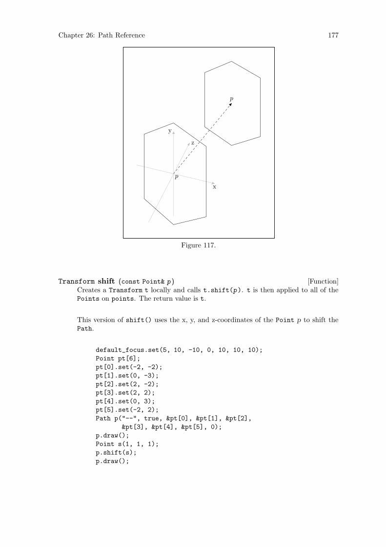
Chapter 26: Path Reference 177
x
y
z
p
p
Figure 117.
[Function]Transform shift (const Point& p )Creates a Transform t locally and calls t.shift(p). t is then applied to all of thePoints on points. The return value is t.
This version of shift() uses the x, y, and z-coordinates of the Point p to shift thePath.
default_focus.set(5, 10, -10, 0, 10, 10, 10);
Point pt[6];
pt[0].set(-2, -2);
pt[1].set(0, -3);
pt[2].set(2, -2);
pt[3].set(2, 2);
pt[4].set(0, 3);
pt[5].set(-2, 2);
Path p("--", true, &pt[0], &pt[1], &pt[2],
&pt[3], &pt[4], &pt[5], 0);
p.draw();
Point s(1, 1, 1);
p.shift(s);
p.draw();
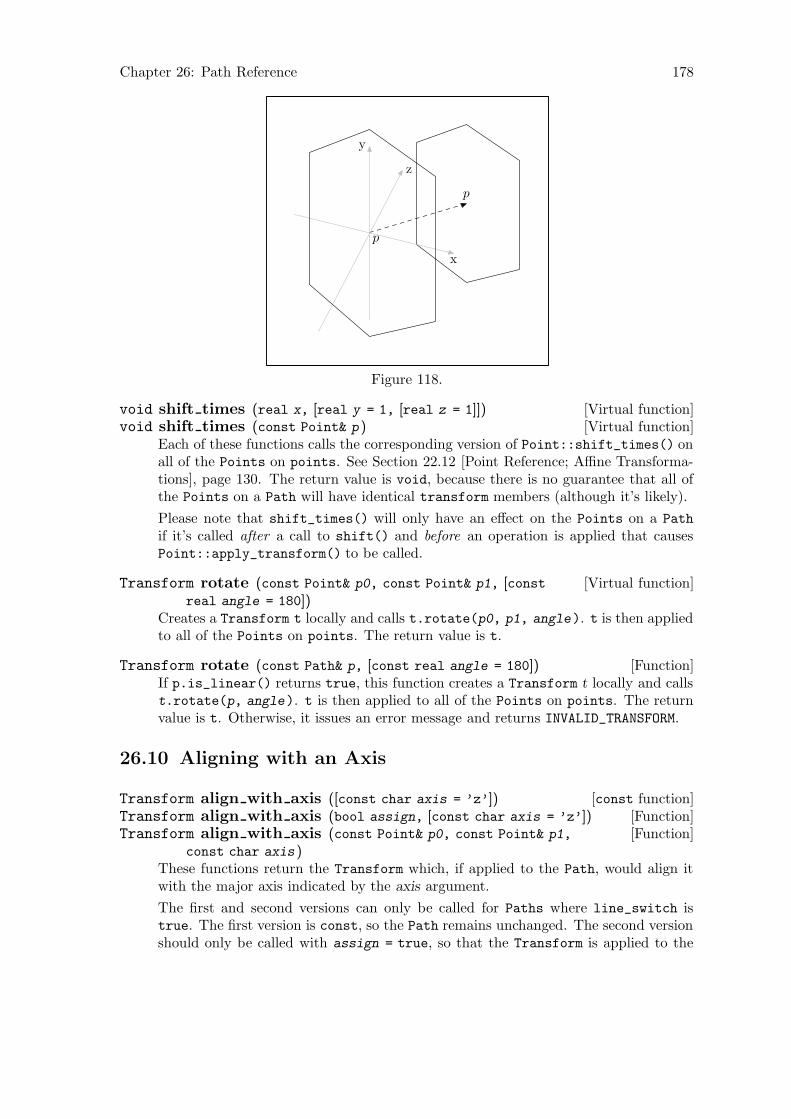
Chapter 26: Path Reference 178
x
y
z
p
p
Figure 118.
[Virtual function]void shift times (real x, [real y = 1, [real z = 1]])[Virtual function]void shift times (const Point& p )
Each of these functions calls the corresponding version of Point::shift_times() onall of the Points on points. See Section 22.12 [Point Reference; Affine Transforma-tions], page 130. The return value is void, because there is no guarantee that all ofthe Points on a Path will have identical transform members (although it’s likely).
Please note that shift_times() will only have an effect on the Points on a Path
if it’s called after a call to shift() and before an operation is applied that causesPoint::apply_transform() to be called.
[Virtual function]Transform rotate (const Point& p0, const Point& p1, [constreal angle = 180])
Creates a Transform t locally and calls t.rotate(p0, p1, angle). t is then appliedto all of the Points on points. The return value is t.
[Function]Transform rotate (const Path& p, [const real angle = 180])If p.is_linear() returns true, this function creates a Transform t locally and callst.rotate(p, angle). t is then applied to all of the Points on points. The returnvalue is t. Otherwise, it issues an error message and returns INVALID_TRANSFORM.
26.10 Aligning with an Axis
[const function]Transform align with axis ([const char axis = ’z’])[Function]Transform align with axis (bool assign, [const char axis = ’z’])[Function]Transform align with axis (const Point& p0, const Point& p1,
const char axis )These functions return the Transform which, if applied to the Path, would align itwith the major axis indicated by the axis argument.
The first and second versions can only be called for Paths where line_switch istrue. The first version is const, so the Path remains unchanged. The second versionshould only be called with assign = true, so that the Transform is applied to the
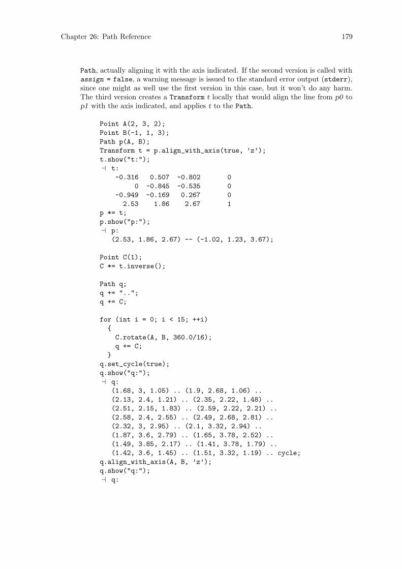
Chapter 26: Path Reference 179
Path, actually aligning it with the axis indicated. If the second version is called withassign = false, a warning message is issued to the standard error output (stderr),since one might as well use the first version in this case, but it won’t do any harm.The third version creates a Transform t locally that would align the line from p0 top1 with the axis indicated, and applies t to the Path.
Point A(2, 3, 2);
Point B(-1, 1, 3);
Path p(A, B);
Transform t = p.align_with_axis(true, ’z’);
t.show("t:");
a t:
-0.316 0.507 -0.802 0
0 -0.845 -0.535 0
-0.949 -0.169 0.267 0
2.53 1.86 2.67 1
p *= t;
p.show("p:");
a p:
(2.53, 1.86, 2.67) -- (-1.02, 1.23, 3.67);
Point C(1);
C *= t.inverse();
Path q;
q += "..";
q += C;
for (int i = 0; i < 15; ++i)
{
C.rotate(A, B, 360.0/16);
q += C;
}
q.set_cycle(true);
q.show("q:");
a q:
(1.68, 3, 1.05) .. (1.9, 2.68, 1.06) ..
(2.13, 2.4, 1.21) .. (2.35, 2.22, 1.48) ..
(2.51, 2.15, 1.83) .. (2.59, 2.22, 2.21) ..
(2.58, 2.4, 2.55) .. (2.49, 2.68, 2.81) ..
(2.32, 3, 2.95) .. (2.1, 3.32, 2.94) ..
(1.87, 3.6, 2.79) .. (1.65, 3.78, 2.52) ..
(1.49, 3.85, 2.17) .. (1.41, 3.78, 1.79) ..
(1.42, 3.6, 1.45) .. (1.51, 3.32, 1.19) .. cycle;
q.align_with_axis(A, B, ’z’);
q.show("q:");
a q:
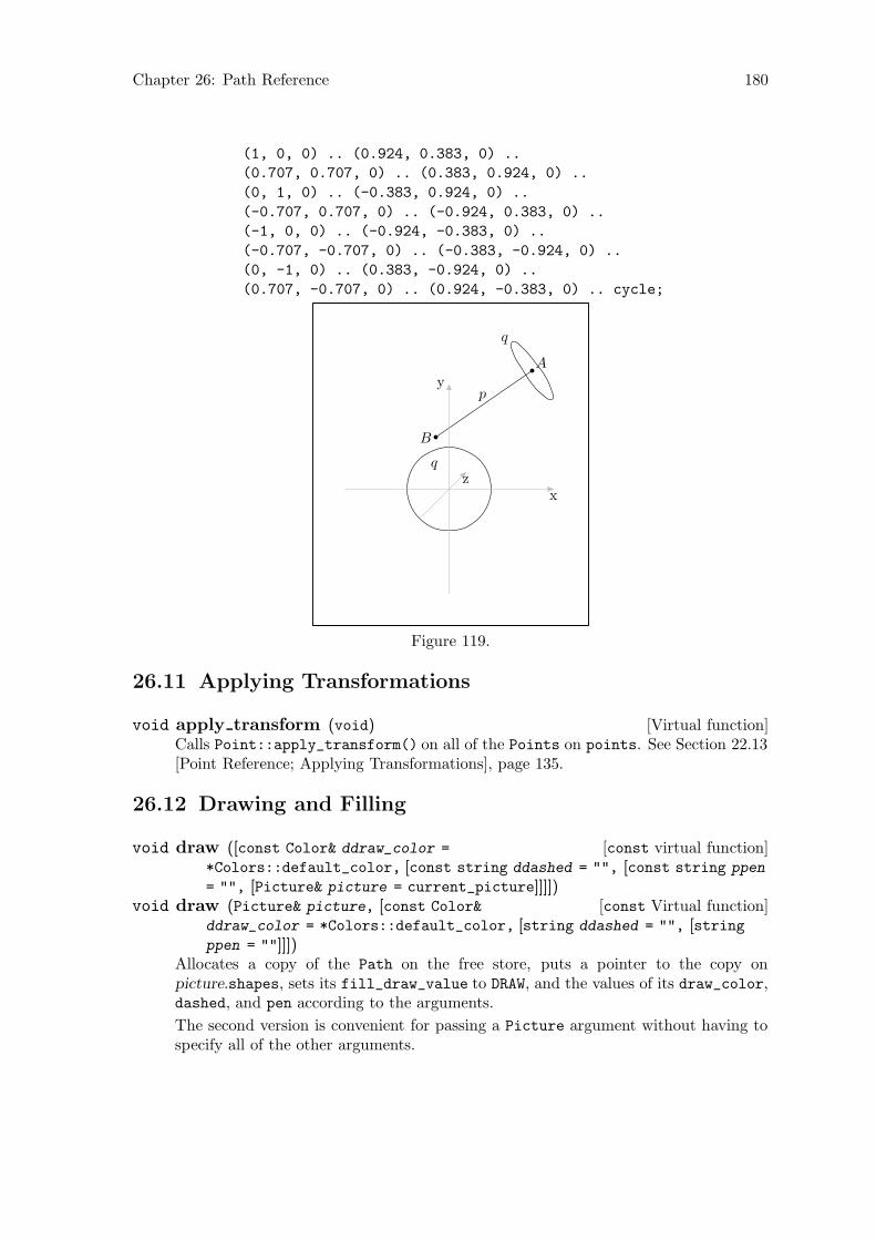
Chapter 26: Path Reference 180
(1, 0, 0) .. (0.924, 0.383, 0) ..
(0.707, 0.707, 0) .. (0.383, 0.924, 0) ..
(0, 1, 0) .. (-0.383, 0.924, 0) ..
(-0.707, 0.707, 0) .. (-0.924, 0.383, 0) ..
(-1, 0, 0) .. (-0.924, -0.383, 0) ..
(-0.707, -0.707, 0) .. (-0.383, -0.924, 0) ..
(0, -1, 0) .. (0.383, -0.924, 0) ..
(0.707, -0.707, 0) .. (0.924, -0.383, 0) .. cycle;
A
B
p
q
q
x
y
z
Figure 119.
26.11 Applying Transformations
[Virtual function]void apply transform (void)Calls Point::apply_transform() on all of the Points on points. See Section 22.13[Point Reference; Applying Transformations], page 135.
26.12 Drawing and Filling
[const virtual function]void draw ([const Color& ddraw_color =
*Colors::default_color, [const string ddashed = "", [const string ppen
= "", [Picture& picture = current_picture]]]])[const Virtual function]void draw (Picture& picture, [const Color&
ddraw_color = *Colors::default_color, [string ddashed = "", [stringppen = ""]]])
Allocates a copy of the Path on the free store, puts a pointer to the copy onpicture.shapes, sets its fill_draw_value to DRAW, and the values of its draw_color,dashed, and pen according to the arguments.
The second version is convenient for passing a Picture argument without having tospecify all of the other arguments.
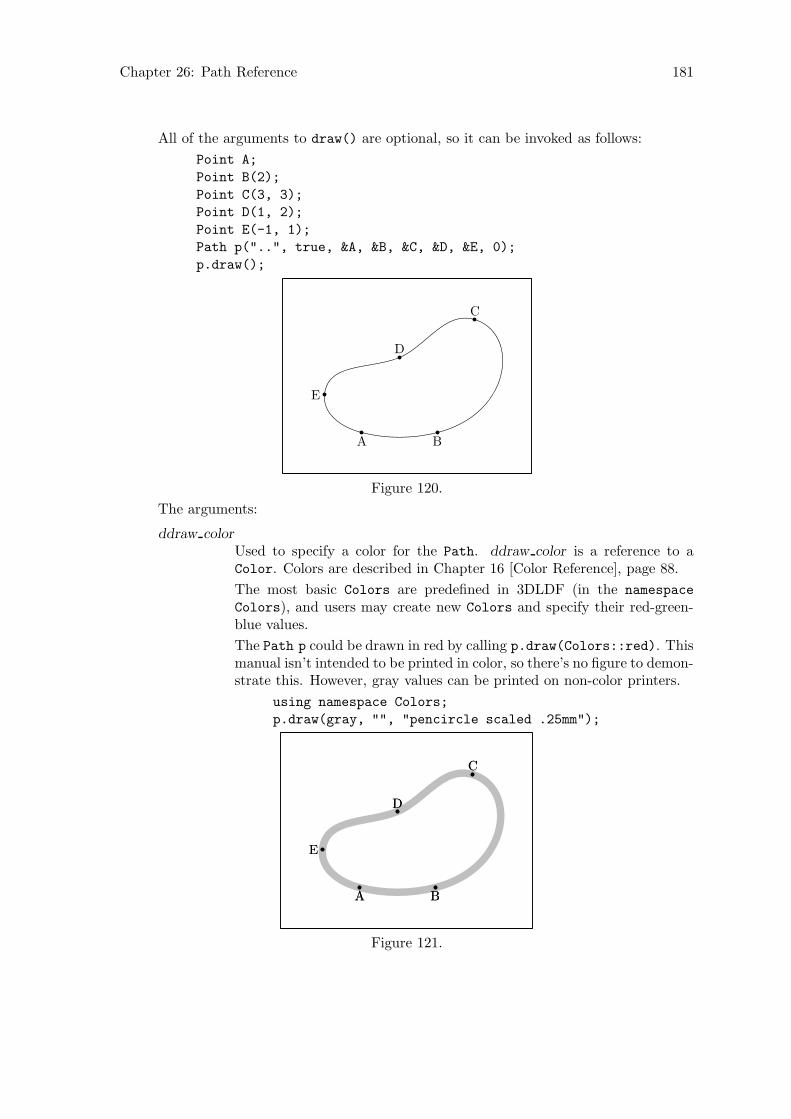
Chapter 26: Path Reference 181
All of the arguments to draw() are optional, so it can be invoked as follows:
Point A;
Point B(2);
Point C(3, 3);
Point D(1, 2);
Point E(-1, 1);
Path p("..", true, &A, &B, &C, &D, &E, 0);
p.draw();
A B
C
D
E
Figure 120.
The arguments:
ddraw color
Used to specify a color for the Path. ddraw color is a reference to aColor. Colors are described in Chapter 16 [Color Reference], page 88.
The most basic Colors are predefined in 3DLDF (in the namespace
Colors), and users may create new Colors and specify their red-green-blue values.
The Path p could be drawn in red by calling p.draw(Colors::red). Thismanual isn’t intended to be printed in color, so there’s no figure to demon-strate this. However, gray values can be printed on non-color printers.
using namespace Colors;
p.draw(gray, "", "pencircle scaled .25mm");
A B
C
D
E
A B
C
D
E
Figure 121.
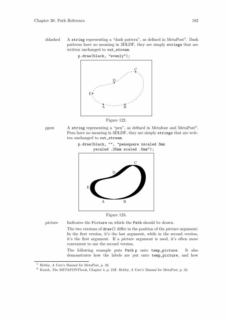
Chapter 26: Path Reference 182
ddashed A string representing a “dash pattern”, as defined in MetaPost5. Dashpatterns have no meaning in 3DLDF, they are simply strings that arewritten unchanged to out_stream.
p.draw(black, "evenly");
A B
C
D
E
Figure 122.
ppen A string representing a “pen”, as defined in Metafont and MetaPost6.Pens have no meaning in 3DLDF, they are simply strings that are writ-ten unchanged to out_stream.
p.draw(black, "", "pensquare xscaled 3mm
yscaled .25mm scaled .5mm");
A B
C
D
E
Figure 123.
picture Indicates the Picture on which the Path should be drawn.
The two versions of draw() differ in the position of the picture argument:In the first version, it’s the last argument, while in the second version,it’s the first argument. If a picture argument is used, it’s often moreconvenient to use the second version.
The following example puts Path p onto temp_picture. It alsodemonstrates how the labels are put onto temp_picture, and how
5 Hobby, A User’s Manual for MetaPost, p. 32.6 Knuth, The METAFONTbook, Chapter 4, p. 21ff. Hobby, A User’s Manual for MetaPost, p. 32.
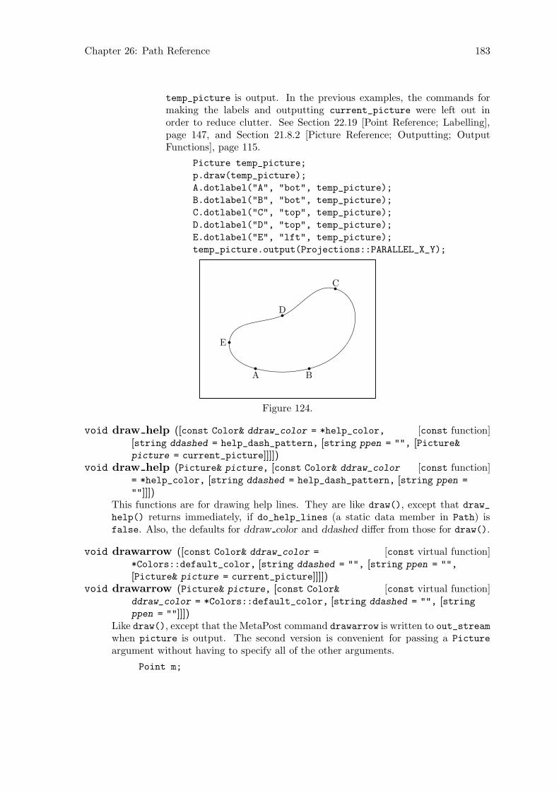
Chapter 26: Path Reference 183
temp_picture is output. In the previous examples, the commands formaking the labels and outputting current_picture were left out inorder to reduce clutter. See Section 22.19 [Point Reference; Labelling],page 147, and Section 21.8.2 [Picture Reference; Outputting; OutputFunctions], page 115.
Picture temp_picture;
p.draw(temp_picture);
A.dotlabel("A", "bot", temp_picture);
B.dotlabel("B", "bot", temp_picture);
C.dotlabel("C", "top", temp_picture);
D.dotlabel("D", "top", temp_picture);
E.dotlabel("E", "lft", temp_picture);
temp_picture.output(Projections::PARALLEL_X_Y);
A B
C
D
E
Figure 124.
[const function]void draw help ([const Color& ddraw_color = *help_color,
[string ddashed = help_dash_pattern, [string ppen = "", [Picture&picture = current_picture]]]])
[const function]void draw help (Picture& picture, [const Color& ddraw_color
= *help_color, [string ddashed = help_dash_pattern, [string ppen =
""]]])This functions are for drawing help lines. They are like draw(), except that draw_
help() returns immediately, if do_help_lines (a static data member in Path) isfalse. Also, the defaults for ddraw color and ddashed differ from those for draw().
[const virtual function]void drawarrow ([const Color& ddraw_color =
*Colors::default_color, [string ddashed = "", [string ppen = "",
[Picture& picture = current_picture]]]])[const virtual function]void drawarrow (Picture& picture, [const Color&
ddraw_color = *Colors::default_color, [string ddashed = "", [stringppen = ""]]])
Like draw(), except that the MetaPost command drawarrow is written to out_streamwhen picture is output. The second version is convenient for passing a Picture
argument without having to specify all of the other arguments.
Point m;

Chapter 26: Path Reference 184
Point n(2, 2);
m.dotlabel("$m$", "bot");
n.dotlabel("$n$");
m.drawarrow(n);
m
n
Figure 125.
[Non-member function]void draw axes ([real dist = 2.5, [string pos_x =
"bot", [string pos_y = "lft", [string pos_z = "bot", [const Color&
ddraw_color = *Colors::default_color, [const string ddashed = "",
[const string ppen = "", [const Point& shift_x = origin, [const Point&
shift_y = origin, [const Point& shift_z = origin, [Picture& picture =
current_picture]]]]]]]]]]])[Non-member function]void draw axes (const Color& ddraw_color, [real dist
= 2.5, [string pos_x = "bot", [string pos_y = "lft", [string pos_z =
"bot", [const string ddashed = "", [const string ppen = "", [constPoint& shift_x = origin, [const Point& shift_y = origin, [const Point&
shift_z = origin, [Picture& picture = current_picture]]]]]]]]]])These functions draw lines centered on the origin, and ending in arrows in the direc-tions of the positive x, y, and z-axes, and labels them with the appropriate letters.draw_axes() is used in many of the figures in this handbook. It can be helpful indetermining whether a Focus has a good “up” direction. See Section 23.1 [FocusReference; Data Members], page 151.
In the first version, all of the arguments are optional. In the second version,ddraw color is required and has been moved to the front of the argument list. Thisversion is often convenient, when a Color other than the default is desired.
The arguments:
dist The length of the lines drawn. The default is 2.5. The value 0 can beused as a dummy argument, if the default for dist is desired, but otherarguments must be specified.
pos x
pos y
pos z The position arguments for the labelling commands for each of the axes.The defaults are "bot" for the x and z-axes, and "lft" for the y-axis.The usual strings for the position of labels can be used, namely: "top","bot", "lft", "rt", "ulft", "urt", "llft", "lrt", and "". If "" isused, that axis is not drawn. This can be useful for parallel projections
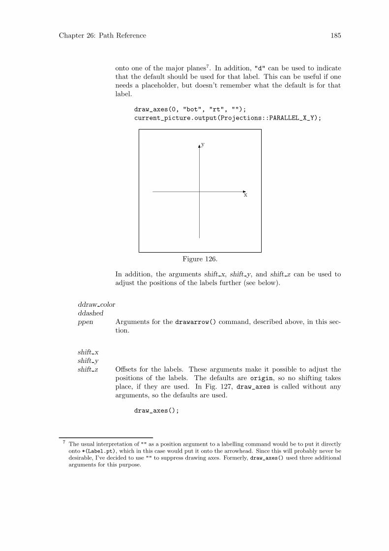
Chapter 26: Path Reference 185
onto one of the major planes7. In addition, "d" can be used to indicatethat the default should be used for that label. This can be useful if oneneeds a placeholder, but doesn’t remember what the default is for thatlabel.
draw_axes(0, "bot", "rt", "");
current_picture.output(Projections::PARALLEL_X_Y);
x
y
Figure 126.
In addition, the arguments shift x, shift y, and shift z can be used toadjust the positions of the labels further (see below).
ddraw color
ddashed
ppen Arguments for the drawarrow() command, described above, in this sec-tion.
shift x
shift y
shift z Offsets for the labels. These arguments make it possible to adjust thepositions of the labels. The defaults are origin, so no shifting takesplace, if they are used. In Fig. 127, draw_axes is called without anyarguments, so the defaults are used.
draw_axes();
7 The usual interpretation of "" as a position argument to a labelling command would be to put it directlyonto *(Label.pt), which in this case would put it onto the arrowhead. Since this will probably never bedesirable, I’ve decided to use "" to suppress drawing axes. Formerly, draw_axes() used three additionalarguments for this purpose.
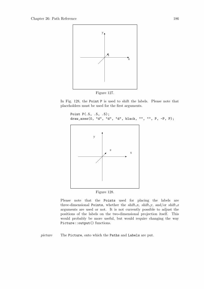
Chapter 26: Path Reference 186
x
y
z
Figure 127.
In Fig. 128, the Point P is used to shift the labels. Please note thatplaceholders must be used for the first arguments.
Point P(.5, .5, .5);
draw_axes(0, "d", "d", "d", black, "", "", P, -P, P);
x
y
z
Figure 128.
Please note that the Points used for placing the labels arethree-dimensional Points, whether the shift x, shift y, and/or shift z
arguments are used or not. It is not currently possible to adjust thepositions of the labels on the two-dimensional projection itself. Thiswould probably be more useful, but would require changing the wayPicture::output() functions.
picture The Picture, onto which the Paths and Labels are put.
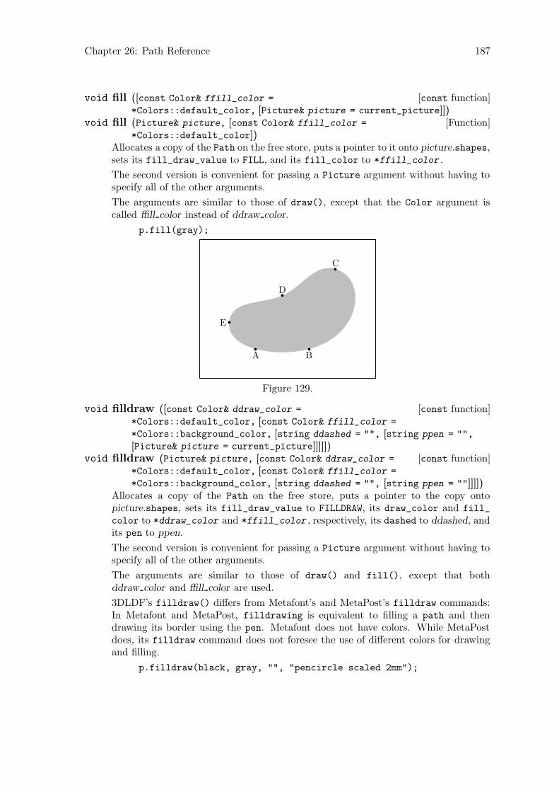
Chapter 26: Path Reference 187
[const function]void fill ([const Color& ffill_color =
*Colors::default_color, [Picture& picture = current_picture]])[Function]void fill (Picture& picture, [const Color& ffill_color =
*Colors::default_color])Allocates a copy of the Path on the free store, puts a pointer to it onto picture.shapes,sets its fill_draw_value to FILL, and its fill_color to *ffill_color .
The second version is convenient for passing a Picture argument without having tospecify all of the other arguments.
The arguments are similar to those of draw(), except that the Color argument iscalled ffill color instead of ddraw color.
p.fill(gray);
A B
C
D
E
Figure 129.
[const function]void filldraw ([const Color& ddraw_color =
*Colors::default_color, [const Color& ffill_color =
*Colors::background_color, [string ddashed = "", [string ppen = "",
[Picture& picture = current_picture]]]]])[const function]void filldraw (Picture& picture, [const Color& ddraw_color =
*Colors::default_color, [const Color& ffill_color =
*Colors::background_color, [string ddashed = "", [string ppen = ""]]]])Allocates a copy of the Path on the free store, puts a pointer to the copy ontopicture.shapes, sets its fill_draw_value to FILLDRAW, its draw_color and fill_
color to *ddraw_color and *ffill_color , respectively, its dashed to ddashed, andits pen to ppen.
The second version is convenient for passing a Picture argument without having tospecify all of the other arguments.
The arguments are similar to those of draw() and fill(), except that bothddraw color and ffill color are used.
3DLDF’s filldraw() differs from Metafont’s and MetaPost’s filldraw commands:In Metafont and MetaPost, filldrawing is equivalent to filling a path and thendrawing its border using the pen. Metafont does not have colors. While MetaPostdoes, its filldraw command does not foresee the use of different colors for drawingand filling.
p.filldraw(black, gray, "", "pencircle scaled 2mm");
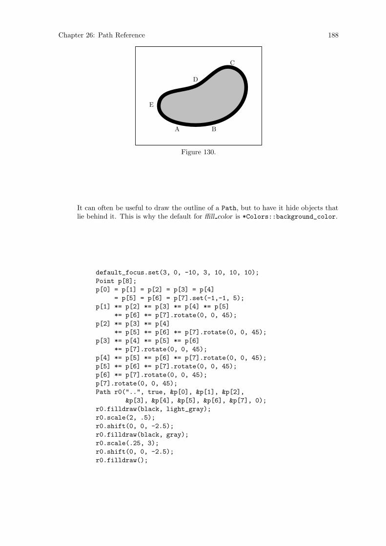
Chapter 26: Path Reference 188
A B
C
D
E
Figure 130.
It can often be useful to draw the outline of a Path, but to have it hide objects thatlie behind it. This is why the default for ffill color is *Colors::background_color.
default_focus.set(3, 0, -10, 3, 10, 10, 10);
Point p[8];
p[0] = p[1] = p[2] = p[3] = p[4]
= p[5] = p[6] = p[7].set(-1,-1, 5);
p[1] *= p[2] *= p[3] *= p[4] *= p[5]
*= p[6] *= p[7].rotate(0, 0, 45);
p[2] *= p[3] *= p[4]
*= p[5] *= p[6] *= p[7].rotate(0, 0, 45);
p[3] *= p[4] *= p[5] *= p[6]
*= p[7].rotate(0, 0, 45);
p[4] *= p[5] *= p[6] *= p[7].rotate(0, 0, 45);
p[5] *= p[6] *= p[7].rotate(0, 0, 45);
p[6] *= p[7].rotate(0, 0, 45);
p[7].rotate(0, 0, 45);
Path r0("..", true, &p[0], &p[1], &p[2],
&p[3], &p[4], &p[5], &p[6], &p[7], 0);
r0.filldraw(black, light_gray);
r0.scale(2, .5);
r0.shift(0, 0, -2.5);
r0.filldraw(black, gray);
r0.scale(.25, 3);
r0.shift(0, 0, -2.5);
r0.filldraw();
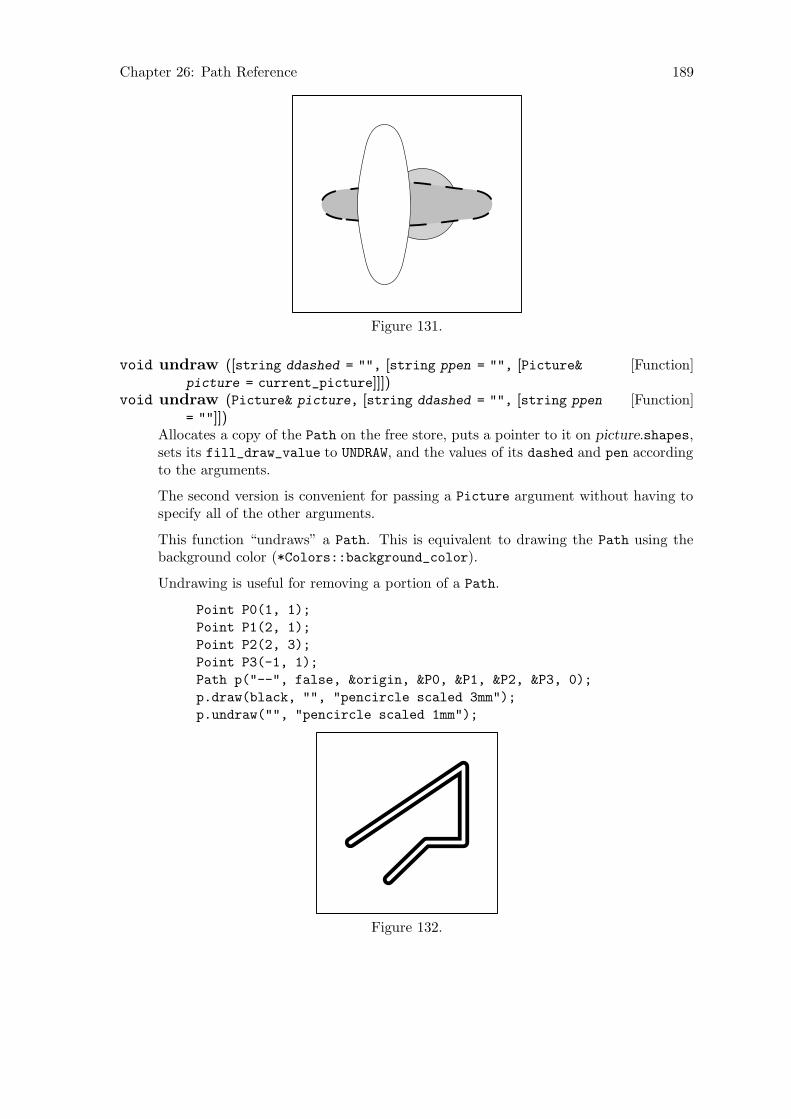
Chapter 26: Path Reference 189
Figure 131.
[Function]void undraw ([string ddashed = "", [string ppen = "", [Picture&picture = current_picture]]])
[Function]void undraw (Picture& picture, [string ddashed = "", [string ppen
= ""]])Allocates a copy of the Path on the free store, puts a pointer to it on picture.shapes,sets its fill_draw_value to UNDRAW, and the values of its dashed and pen accordingto the arguments.
The second version is convenient for passing a Picture argument without having tospecify all of the other arguments.
This function “undraws” a Path. This is equivalent to drawing the Path using thebackground color (*Colors::background_color).
Undrawing is useful for removing a portion of a Path.
Point P0(1, 1);
Point P1(2, 1);
Point P2(2, 3);
Point P3(-1, 1);
Path p("--", false, &origin, &P0, &P1, &P2, &P3, 0);
p.draw(black, "", "pencircle scaled 3mm");
p.undraw("", "pencircle scaled 1mm");
Figure 132.
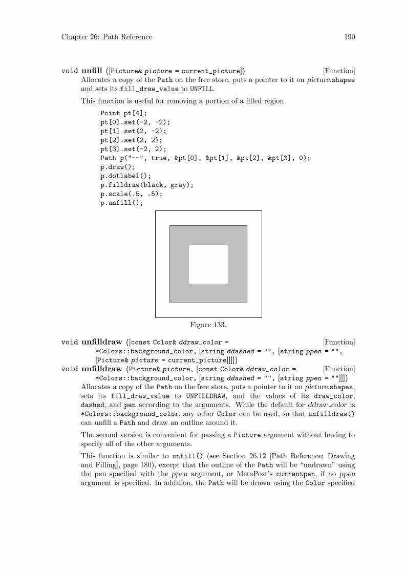
Chapter 26: Path Reference 190
[Function]void unfill ([Picture& picture = current_picture])Allocates a copy of the Path on the free store, puts a pointer to it on picture.shapesand sets its fill_draw_value to UNFILL
This function is useful for removing a portion of a filled region.
Point pt[4];
pt[0].set(-2, -2);
pt[1].set(2, -2);
pt[2].set(2, 2);
pt[3].set(-2, 2);
Path p("--", true, &pt[0], &pt[1], &pt[2], &pt[3], 0);
p.draw();
p.dotlabel();
p.filldraw(black, gray);
p.scale(.5, .5);
p.unfill();
Figure 133.
[Function]void unfilldraw ([const Color& ddraw_color =
*Colors::background_color, [string ddashed = "", [string ppen = "",
[Picture& picture = current_picture]]]])[Function]void unfilldraw (Picture& picture, [const Color& ddraw_color =
*Colors::background_color, [string ddashed = "", [string ppen = ""]]])Allocates a copy of the Path on the free store, puts a pointer to it on picture.shapes,sets its fill_draw_value to UNFILLDRAW, and the values of its draw_color,dashed, and pen according to the arguments. While the default for ddraw color is*Colors::background_color, any other Color can be used, so that unfilldraw()
can unfill a Path and draw an outline around it.
The second version is convenient for passing a Picture argument without having tospecify all of the other arguments.
This function is similar to unfill() (see Section 26.12 [Path Reference; Drawingand Filling], page 180), except that the outline of the Path will be “undrawn” usingthe pen specified with the ppen argument, or MetaPost’s currentpen, if no ppen
argument is specified. In addition, the Path will be drawn using the Color specified
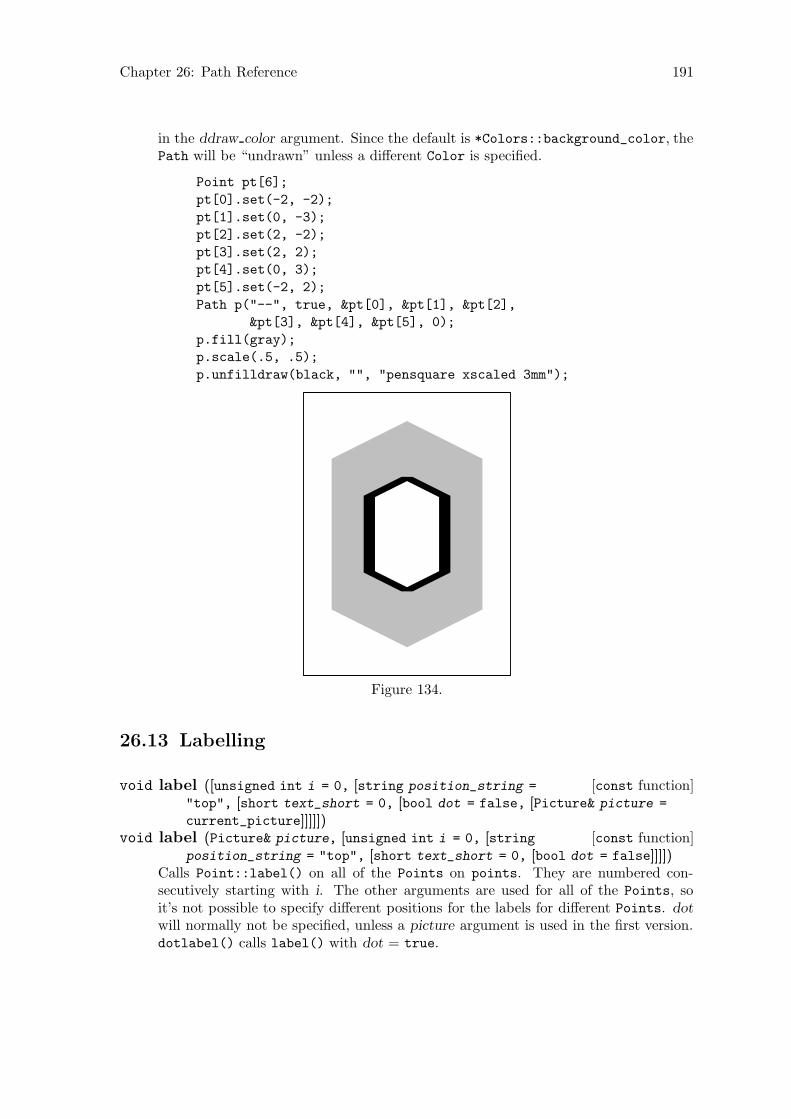
Chapter 26: Path Reference 191
in the ddraw color argument. Since the default is *Colors::background_color, thePath will be “undrawn” unless a different Color is specified.
Point pt[6];
pt[0].set(-2, -2);
pt[1].set(0, -3);
pt[2].set(2, -2);
pt[3].set(2, 2);
pt[4].set(0, 3);
pt[5].set(-2, 2);
Path p("--", true, &pt[0], &pt[1], &pt[2],
&pt[3], &pt[4], &pt[5], 0);
p.fill(gray);
p.scale(.5, .5);
p.unfilldraw(black, "", "pensquare xscaled 3mm");
Figure 134.
26.13 Labelling
[const function]void label ([unsigned int i = 0, [string position_string =
"top", [short text_short = 0, [bool dot = false, [Picture& picture =
current_picture]]]]])[const function]void label (Picture& picture, [unsigned int i = 0, [string
position_string = "top", [short text_short = 0, [bool dot = false]]]])Calls Point::label() on all of the Points on points. They are numbered con-secutively starting with i. The other arguments are used for all of the Points, soit’s not possible to specify different positions for the labels for different Points. dot
will normally not be specified, unless a picture argument is used in the first version.dotlabel() calls label() with dot = true.
Chapter 26: Path Reference 192
The second version is convenient for passing a Picture argument without having tospecify all of the other arguments.
[const function]void dotlabel ([unsigned int i = 0, [string position_string =
"top", [short text_short = 0, Picture& picture = current_picture]]])[const function]void dotlabel (Picture& picture, [unsigned int i = 0, [string
position_string = "top", [short text_short = 0]]])Like label(), except that the Points are dotted.
26.14 Showing
[const function]void show ([string text = "", [char coords = ’w’, [const bool
do_persp = true, [const bool do_apply = true, [Focus* f = 0, [constunsigned short proj = Projections::PERSP, [const real factor = 1]]]]]]])
Prints information about the Path to standard output (stdout). text is simply printedout, unless it’s the empty string, in which case "Path:" is printed out. coords indi-cates which set of coordinates should be shown. Valid values are ’w’ for the world_
coordinates, ’p’ for the projective_coordinates, ’u’ for the user_coordinates,and ’v’ for the view_coordinates, whereby the latter two are currently not in use(see Section 22.1 [Point Reference; Data Members], page 119). If do apply is true,apply_transform() is called on each Point, updating its world_coordinates andresetting its transform. Otherwise, it’s not. The arguments do persp, f, proj, andfactor are only relevant when showing projective_coordinates. If do_persp istrue, the Points are projected using the values of f, proj, and factor (see Section 26.16[Path Reference; Outputting], page 197). Otherwise, the values currently stored inprojective_coordinates are shown. The Points and connectors are printed out al-ternately to standard output, followed by the word “cycle”, if cycle_switch = true.8
default_focus.set(0, 3, -10, 0, 3, 10, 10);
Reg_Polygon r(origin, 5, 3, 45);
r.fill(gray);
Point p[10];
for (int i = 0; i < 5; ++i)
p[i] = r.get_point(i);
p[5] = Point::intersection_point(p[4], p[0], p[2], p[1]).pt;
p[6] = Point::intersection_point(p[0], p[1], p[2], p[3]).pt;
p[7] = Point::intersection_point(p[1], p[2], p[4], p[3]).pt;
p[8] = Point::intersection_point(p[2], p[3], p[0], p[4]).pt;
p[9] = Point::intersection_point(p[3], p[4], p[0], p[1]).pt;
Path q("--", true, &p[0], &p[5], &p[1], &p[6], &p[2], &p[7],
&p[3], &p[8], &p[4], &p[9], 0);
q.draw();
q.show("q:");
a q:
fill_draw_value == 0
8 The following example shows only one Point per line. In actual use, two Points are shown, but thiscauses overfull boxes in Texinfo.

Chapter 26: Path Reference 193
(0, 1.06066, 1.06066)
-- (-2.30826, 2.24651, 2.24651)
-- (-1.42658, 0.327762, 0.327762)
-- (-3.73485, -0.858092, -0.858092)
-- (-0.881678, -0.858092, -0.858092)
-- (4.92996e-07, -2.77684, -2.77684)
-- (0.881678, -0.858092, -0.858092)
-- (3.73485, -0.858092, -0.858092)
-- (1.42658, 0.327762, 0.327762)
-- (2.30826, 2.24651, 2.24651) -- cycle;
q.show("q:", ’p’);
a q:
fill_draw_value == 0
Projective coordinates.
(0, -1.75337, 0.0958948)
-- (-1.88483, -0.615265, 0.183441)
-- (-1.38131, -2.58743, 0.031736)
-- (-4.08541, -4.22023, -0.0938636)
-- (-0.964435, -4.22023, -0.0938636)
-- (0, -7.99767, -0.384436)
-- (0.964436, -4.22023, -0.0938636)
-- (4.08541, -4.22023, -0.0938636)
-- (1.38131, -2.58743, 0.031736)
-- (1.88483, -0.615266, 0.183441) -- cycle;
0
1
2 3
4
5
6
7
8
9
Figure 135.
Chapter 26: Path Reference 194
[Function]void show colors ([bool = false])Shows the values of draw_color and fill_color. These will normally be 0, unlessthe Path is on a Picture.
26.15 Querying
[const function]bool is on free store (void)Returns true, if the Path was dynamically allocated on the free store, otherwisefalse.
[const virtual function]bool is planar ([const bool verbose = false, [stringtext = ""]])
Uses get_normal() to determine whether the Path is planar or not. Returns true,if it is, otherwise false. If verbose is true, text is written to standard output, or“Path:”, if text is the empty string, followed by a message saying whether the Path
is planar or not.
[const function]bool is linear ([const bool verbose = false, [string text =
""]])Returns true, if line_switch is true. Otherwise, is_linear() uses get_normal()to determine whether the Path is linear. If it is, is_linear() returns true, otherwisefalse.
[Inline const function]bool is cycle (void)Returns true if the Path is cyclical, i.e., cycle_switch = true, otherwise false.Only cyclical Paths are fillable.
[Inline function]int size (void)Returns the number of Points on points, i.e., points.size().
[Inline const function]bool get line switch (void)Returns the value of line_switch. line_switch is only true, if the Path was created,directly or indirectly, using the constructor taking two Point arguments only. SeeSection 26.2 [Path Reference; Constructors and Setting Functions], page 167.
[Function]real slope ([char a = ’x’, [char b = ’y’]])Returns the slope of the Path in the plane indicated by the arguments, if is_linear()returns true. Otherwise, slope() issues an error message and returns INVALID_REAL.
[const function]Path subpath (size_t start, size_t end, [const bool cycle =
false, [const string connector = ""]])Returns a new Path using points[start] through points[end - 1]. If cycle istrue, then the new Path will be a cycle, whether *this is or not. One optionalconnector argument can be used. If it is, it will be the only connector. Otherwise,the appropriate connectors from *this are used.
start must be < end. It is not possible to have start > end, even if *this is a cycle.
[const function]const Point& get point (const unsigned short a )Returns the Point *points[a], if a < points.size() and the Path is non-empty,otherwise INVALID_POINT.
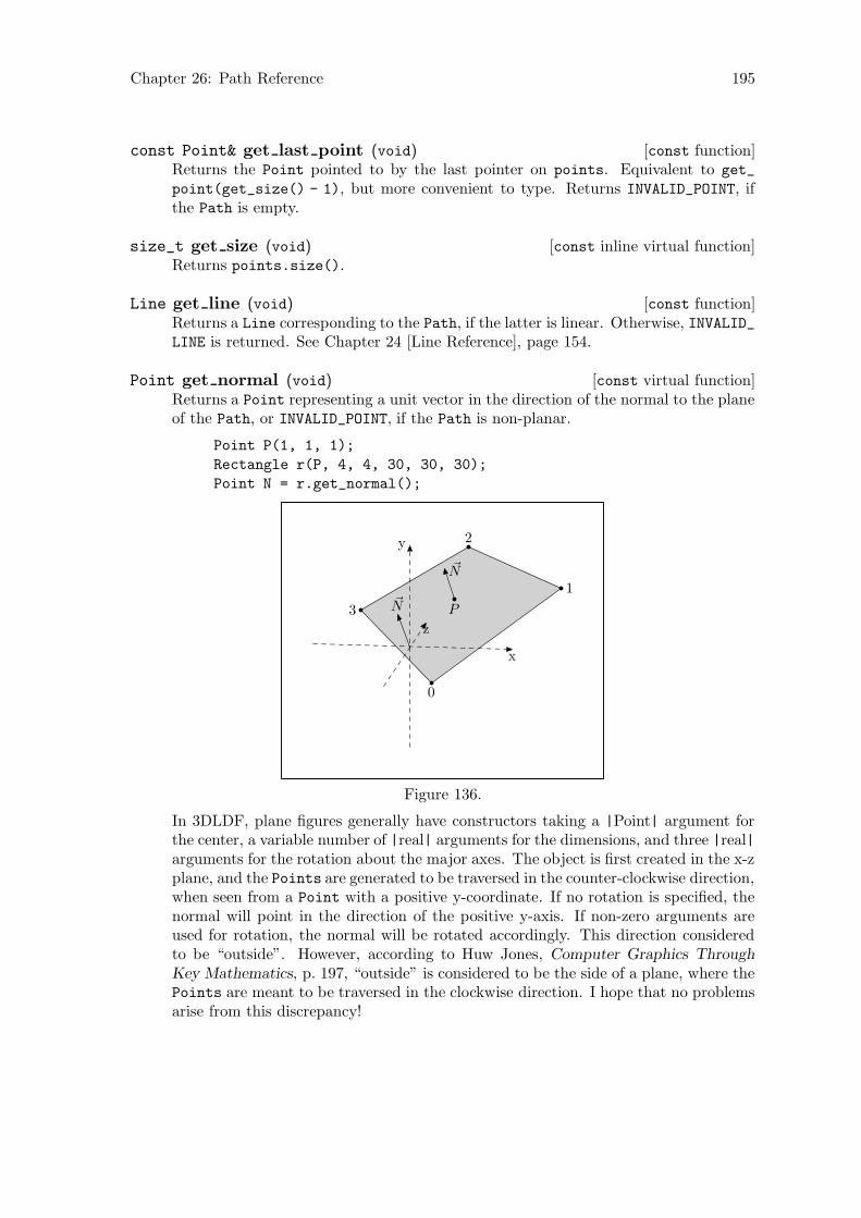
Chapter 26: Path Reference 195
[const function]const Point& get last point (void)Returns the Point pointed to by the last pointer on points. Equivalent to get_
point(get_size() - 1), but more convenient to type. Returns INVALID_POINT, ifthe Path is empty.
[const inline virtual function]size_t get size (void)Returns points.size().
[const function]Line get line (void)Returns a Line corresponding to the Path, if the latter is linear. Otherwise, INVALID_LINE is returned. See Chapter 24 [Line Reference], page 154.
[const virtual function]Point get normal (void)Returns a Point representing a unit vector in the direction of the normal to the planeof the Path, or INVALID_POINT, if the Path is non-planar.
Point P(1, 1, 1);
Rectangle r(P, 4, 4, 30, 30, 30);
Point N = r.get_normal();
P
0
1
2
3~N
~N
x
y
z
Figure 136.
In 3DLDF, plane figures generally have constructors taking a |Point| argument forthe center, a variable number of |real| arguments for the dimensions, and three |real|arguments for the rotation about the major axes. The object is first created in the x-zplane, and the Points are generated to be traversed in the counter-clockwise direction,when seen from a Point with a positive y-coordinate. If no rotation is specified, thenormal will point in the direction of the positive y-axis. If non-zero arguments areused for rotation, the normal will be rotated accordingly. This direction consideredto be “outside”. However, according to Huw Jones, Computer Graphics Through
Key Mathematics, p. 197, “outside” is considered to be the side of a plane, where thePoints are meant to be traversed in the clockwise direction. I hope that no problemsarise from this discrepancy!
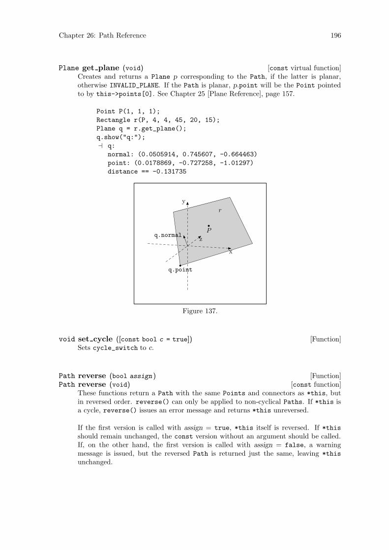
Chapter 26: Path Reference 196
[const virtual function]Plane get plane (void)Creates and returns a Plane p corresponding to the Path, if the latter is planar,otherwise INVALID_PLANE. If the Path is planar, p.point will be the Point pointedto by this->points[0]. See Chapter 25 [Plane Reference], page 157.
Point P(1, 1, 1);
Rectangle r(P, 4, 4, 45, 20, 15);
Plane q = r.get_plane();
q.show("q:");
a q:
normal: (0.0505914, 0.745607, -0.664463)
point: (0.0178869, -0.727258, -1.01297)
distance == -0.131735
P
q.point
q.normal
r
x
y
z
Figure 137.
[Function]void set cycle ([const bool c = true])Sets cycle_switch to c.
[Function]Path reverse (bool assign )[const function]Path reverse (void)
These functions return a Path with the same Points and connectors as *this, butin reversed order. reverse() can only be applied to non-cyclical Paths. If *this isa cycle, reverse() issues an error message and returns *this unreversed.
If the first version is called with assign = true, *this itself is reversed. If *thisshould remain unchanged, the const version without an argument should be called.If, on the other hand, the first version is called with assign = false, a warningmessage is issued, but the reversed Path is returned just the same, leaving *this
unchanged.
Chapter 26: Path Reference 197
26.16 Outputting
[Function]bool project (const Focus& f, const unsigned short proj, real
factor )Calls Point::project(f, proj, factor) on the Points on the Path. IfPoint::project() fails (i.e., returns false), for any of the Points, this functionreturns false. Otherwise, it returns true.
[Function]vector<Shape*> extract (const Focus& f, const unsigned short
proj, real factor )Checks that the Points on points can be projected using the values for f, proj, andfactor. If they can, a vector<Shape*> containing only this is returned. Called inPicture::output().
[Virtual function]bool set extremes (void)Sets the appropriate elements in projective_extremes to the minimum and max-imum values of the x, y, and z-coordinates of the Points on the Path. Used inPicture::output() for determining whether a Path can be output using the argu-ments passed to Picture::output().
[Inline const virtual function]const valarray<real> get extremes (void)Returns projective_extremes. Used in Picture::output().
[const virtual function]real get minimum z (void)[const virtual function]real get mean z (void)[const virtual function]real get maximum z (void)
These functions return the minimum, mean, or maximum value, respectively, of thez-coordinates of the Points on the Path. Used in the surface hiding algorithm inPicture::output().
[Virtual function]void suppress output (void)Called in Picture::output(). Sets do_output to false, if the Path cannot beoutput using the arguments passed to Picture::output().
[Virtual function]void unsuppress output (void)Called in Picture::output(). Resets do_output to true after output() iscalled on the Shapes on shapes in a Picture, so that the Path can be outputif Picture::output() is called again, with arguments that allow the Path to beoutput.
[Virtual function]void output (void)Called in Picture::output(). Writes the MetaPost code to out_stream for drawing,filling, filldrawing, undrawing, unfilling, or unfilldrawing the Path, if the latter wasprojectable using the arguments passed to Picture::output().
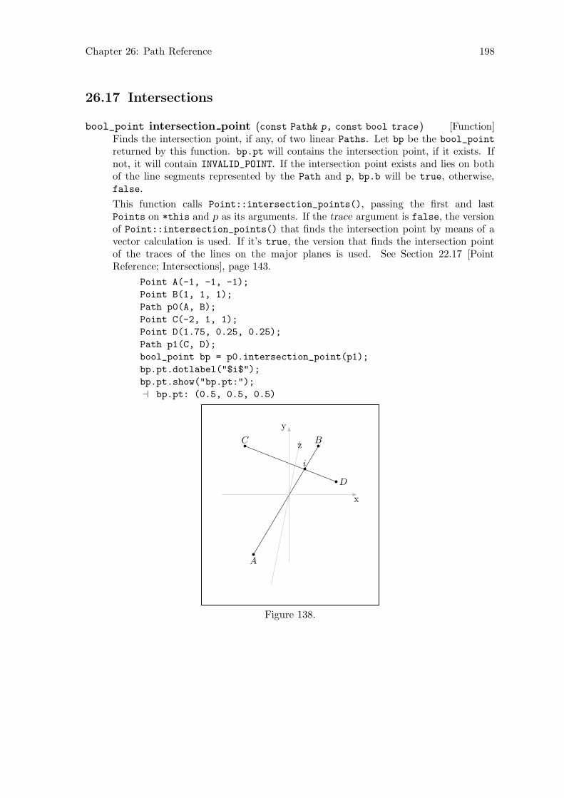
Chapter 26: Path Reference 198
26.17 Intersections
[Function]bool_point intersection point (const Path& p, const bool trace )Finds the intersection point, if any, of two linear Paths. Let bp be the bool_point
returned by this function. bp.pt will contains the intersection point, if it exists. Ifnot, it will contain INVALID_POINT. If the intersection point exists and lies on bothof the line segments represented by the Path and p, bp.b will be true, otherwise,false.
This function calls Point::intersection_points(), passing the first and lastPoints on *this and p as its arguments. If the trace argument is false, the versionof Point::intersection_points() that finds the intersection point by means of avector calculation is used. If it’s true, the version that finds the intersection pointof the traces of the lines on the major planes is used. See Section 22.17 [PointReference; Intersections], page 143.
Point A(-1, -1, -1);
Point B(1, 1, 1);
Path p0(A, B);
Point C(-2, 1, 1);
Point D(1.75, 0.25, 0.25);
Path p1(C, D);
bool_point bp = p0.intersection_point(p1);
bp.pt.dotlabel("$i$");
bp.pt.show("bp.pt:");
a bp.pt: (0.5, 0.5, 0.5)
i
A
BC
D
x
y
z
Figure 138.
Chapter 27: Polygon Reference 199
27 Polygon Reference
Class Polygon is defined in ‘polygons.web’, and is derived from Path, using public deriva-tion.
Polygon is mainly intended for use as a base class for more specialized kinds of polygons.Currently, the classes Reg_Polygon (regular polygon) and Rectangle are defined. SeeChapter 28 [Regular Polygon Reference], page 205, and Chapter 29 [Rectangle Reference],page 211.
27.1 Data Members
[Private variable]Point centerThe center of the Polygon, if it has one. However, a Polygon need not have a center.If it doesn’t, center should be set to INVALID_POINT.
27.2 Operators
[Virtual operator]Transform operator*= (const Transform& t )Multiplies a Polygon by the Transform t. Similar to Path::operator*=(const
Transform& t), except that center is transformed as well. See Section 26.4 [PathReference; Operators], page 171.
27.3 Querying
[Virtual function]const Point& get center (void)[const function]Point get center (void)
These functions return center. If the Polygon doesn’t contain any Points, a warningis issued, and INVALID_POINT is returned.
Chapter 27: Polygon Reference 200
27.4 Affine Transformations
[Virtual function]Transform rotate (const real x, [const real y = 0, [constreal z = 0]])
[Virtual function]Transform rotate (const Point& p0, const Point& p1, [constreal angle = 180])
[Virtual function]Transform rotate (const Path& p, [const real angle = 180])[Virtual function]Transform scale (real x, [real y = 1, [real z = 1]])[Virtual function]Transform shear (real xy, [real xz = 0, [real yx = 0, [real
yz = 0, [real zx = 0, [real zy = 0]]]]])[Virtual function]Transform shift (real x, [real y = 0, [real z = 0]])[Virtual function]Transform shift (const Point& p )[Virtual function]void shift times (real x, [real y = 1, [real z = 1]])[Virtual function]void shift times (const Point& p )
The affine transformation functions for Polygon differ from the Path versions onlyin that center is transformed as well. See Section 26.9 [Path Reference; AffineTransformations], page 174.
Please note, that the classes currently derived from Polygon, namely Reg_Polygon
and Rectangle, currently inherit these functions from Polygon. The problem withthis is, that they have data members, which are not recalculated when a Reg_Polygon
or Rectangle is transformed. I plan to do something about this soon! It will also benecessary to add the function Reg_Polygon::is_reg_polygonal(), in order to testwhether operations on a Reg_Polygon have caused it to become irregular and/or non-polygonal. Similarly, the function Rectangle::is_rectangular()must be added, totest whether operations on a Rectangle has caused it to become non-rectangular. SeeSection 28.1 [Regular Polygon Reference; Data Members], page 205, and Section 29.1[Rectangle Reference; Data Members], page 211.
27.5 Intersections
[const function]bool_point_pair intersection points (const Point& p0,
const Point& p1 )[const function]bool_point_pair intersection points (const Path& p )
These functions find the intersections of the Polygon and a line. In the first version,the Point arguments are the end points of the line. The argument to the secondversion must be a linear Path.
A line and a regular polygon or rectangle1 can intersect at two points at most. Let b bea bool_point_pair returned by intersection_points(). If no intersection pointsare found, b.first.pt and b.second.pt will be INVALID_POINT, and b.first.b
and b.second.b will be false. If a single intersection point is found, the correspond-ing Point will be stored in b.first.pt. If the Point is on the line segment −−→p0p1,b.first.b will be true, otherwise false. If a second intersection point is found, itwill be stored in b.second.pt, and b.second.b is set analogously to b.first.b.
1 Reg_Polygon and Rectangle are currently the only classes derived from Polygon.
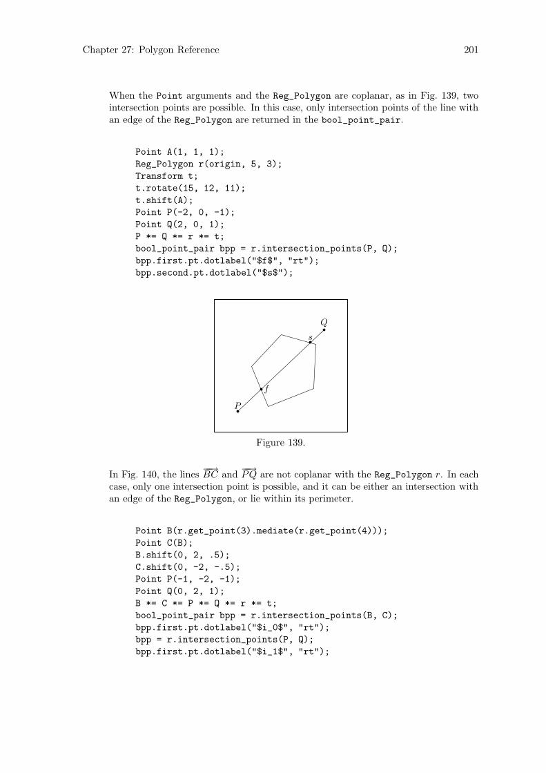
Chapter 27: Polygon Reference 201
When the Point arguments and the Reg_Polygon are coplanar, as in Fig. 139, twointersection points are possible. In this case, only intersection points of the line withan edge of the Reg_Polygon are returned in the bool_point_pair.
Point A(1, 1, 1);
Reg_Polygon r(origin, 5, 3);
Transform t;
t.rotate(15, 12, 11);
t.shift(A);
Point P(-2, 0, -1);
Point Q(2, 0, 1);
P *= Q *= r *= t;
bool_point_pair bpp = r.intersection_points(P, Q);
bpp.first.pt.dotlabel("$f$", "rt");
bpp.second.pt.dotlabel("$s$");
P
Q
f
s
Figure 139.
In Fig. 140, the lines−−→BC and
−−→PQ are not coplanar with the Reg_Polygon r. In each
case, only one intersection point is possible, and it can be either an intersection withan edge of the Reg_Polygon, or lie within its perimeter.
Point B(r.get_point(3).mediate(r.get_point(4)));
Point C(B);
B.shift(0, 2, .5);
C.shift(0, -2, -.5);
Point P(-1, -2, -1);
Point Q(0, 2, 1);
B *= C *= P *= Q *= r *= t;
bool_point_pair bpp = r.intersection_points(B, C);
bpp.first.pt.dotlabel("$i_0$", "rt");
bpp = r.intersection_points(P, Q);
bpp.first.pt.dotlabel("$i_1$", "rt");

Chapter 27: Polygon Reference 202
B
C
P
Q
i0i1
Figure 140.
In Fig. 141, the intersection point of r with the line−−→PQ does not lie on the line
segment PQ.
bpp = r.intersection_points(P, Q);
bpp.first.pt.dotlabel("$i$", "rt");
cout << "bpp.first.b == " << bpp.first.b << endl << flush;
a bpp.first.b == 0
P
Q
i
Figure 141.
[const function]vector<Point> intersection points (const Polygon& r )Finds the intersection points of two Polygons. Let v be the vector<Point> returnedby intersection_points(). If the Polygons are coplanar, v will contain the inter-section points of the edges of the Polygons, as in Fig. 142.
Rectangle r(origin, 4, 4);
Reg_Polygon rp(origin, 5, 5, 0, 36);
rp.shift(0, 0, .25);
vector <Point> v = r.intersection_points(rp);
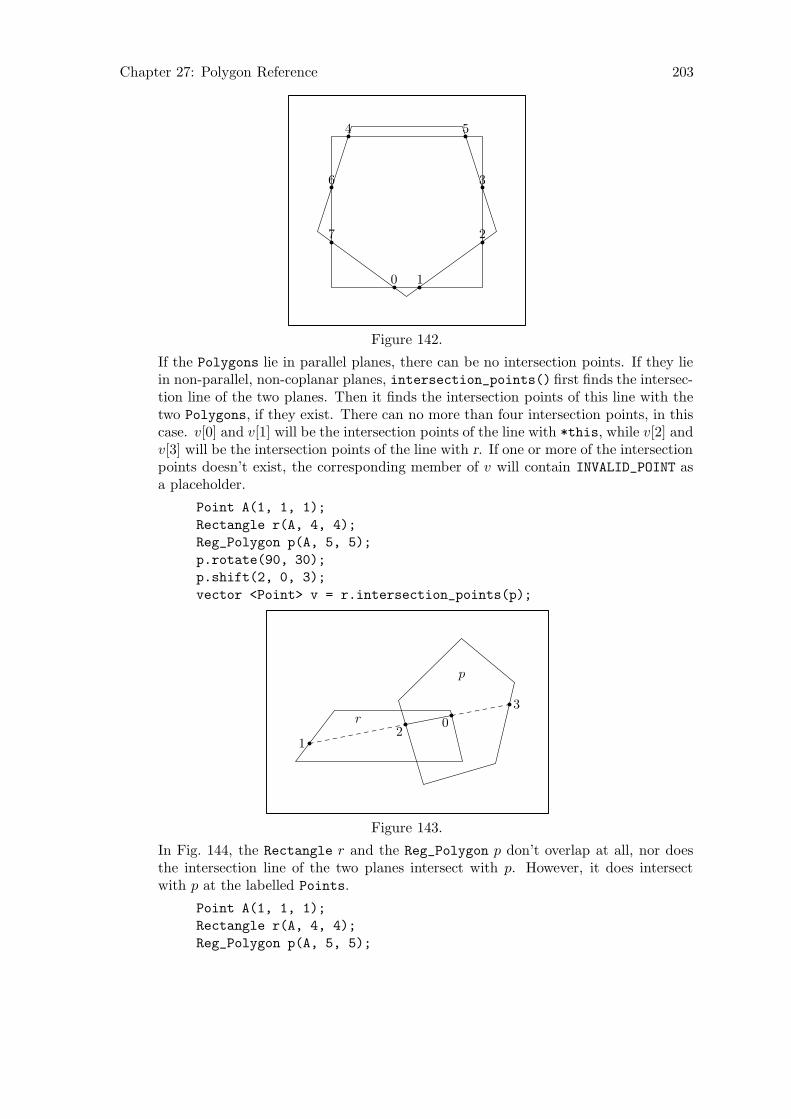
Chapter 27: Polygon Reference 203
0 1
2
3
4 5
6
7
Figure 142.
If the Polygons lie in parallel planes, there can be no intersection points. If they liein non-parallel, non-coplanar planes, intersection_points() first finds the intersec-tion line of the two planes. Then it finds the intersection points of this line with thetwo Polygons, if they exist. There can no more than four intersection points, in thiscase. v[0] and v[1] will be the intersection points of the line with *this, while v[2] andv[3] will be the intersection points of the line with r. If one or more of the intersectionpoints doesn’t exist, the corresponding member of v will contain INVALID_POINT asa placeholder.
Point A(1, 1, 1);
Rectangle r(A, 4, 4);
Reg_Polygon p(A, 5, 5);
p.rotate(90, 30);
p.shift(2, 0, 3);
vector <Point> v = r.intersection_points(p);
r
p
0
12
3
Figure 143.
In Fig. 144, the Rectangle r and the Reg_Polygon p don’t overlap at all, nor doesthe intersection line of the two planes intersect with p. However, it does intersectwith p at the labelled Points.
Point A(1, 1, 1);
Rectangle r(A, 4, 4);
Reg_Polygon p(A, 5, 5);

Chapter 27: Polygon Reference 204
p.rotate(90, 30);
p.shift(4, 3, 3);
vector <Point> v = r.intersection_points(p);
int i = 0;
for (vector<Point>::iterator iter = v.begin();
iter != v.end(); ++iter)
iter->dotlabel(i++, "bot");
r
p
0
1
Figure 144.

Chapter 28: Regular Polygon Reference 205
28 Regular Polygon Reference
Class Reg_Polygon is defined in ‘polygons.web’, and is derived from Polygon, using publicderivation.
As noted above in Section 27.4 [Polygon Reference; Affine Transformations], page 200,class Reg_Polygon, like class Rectangle, currently inherits its transformation functionsand operator*=(const Transform&) from Polygon. Consequently, the data members ofa Reg_Polygon, except for center, are not recalculated when it’s transformed. I plan tochange this soon! It will also be necessary to add the function Reg_Polygon::is_reg_
polygonal(), in order to test whether a Reg_Polygon is still regular and polygonal.
28.1 Data Members
[Private variable]real internal angleThe angle at the center of the Reg_Polygon of the triangle formed by the center andtwo adjacent corners. If n is the number of sides of a Reg_Polygon, internal_anglewill be 360.0/n, so internal_angle will be 120 for a regular triangle, 90 for a square,72 for a pentagon, etc.
[Private variable]real radiusThe radius of the surrounding circle for a Reg_Polygon (Umkreis).
[Private variable]unsigned short sidesThe number of sides of a Reg_Polygon.
[Private variable]bool on free storetrue, if the Reg_Polygon was dynamically allocated on the free store, otherwisefalse. Dynamic allocation of Reg_Polygons should only be performed by create_
new<Reg_Polygon>(), which sets on_free_store to true.
28.2 Constructors and Setting Functions
[Default constructor]void Reg Polygon (void)Creates an empty Reg_Polygon.
[Constructor]void Reg Polygon (const Point& ccenter, const unsigned short
ssides, const real ddiameter, [const real angle_x = 0, [const real
angle_y = 0, [const real angle_z = 0]]])Creates a Reg_Polygon in the x-z plane, centered at the origin, with the number ofsides specified by ssides and with radius = ddiameter/2.
The Reg_Polygon is rotated about the x, y, and z-axes in that order by the anglesgiven by angle x, angle y, and angle z, respectively, if any one of them is non-zero.Finally, the Reg_Polygon is shifted such that its center is located at ccenter.
Reg_Polygon r(origin, 3, 2.75, 10, 15, 12.5);
r.draw();
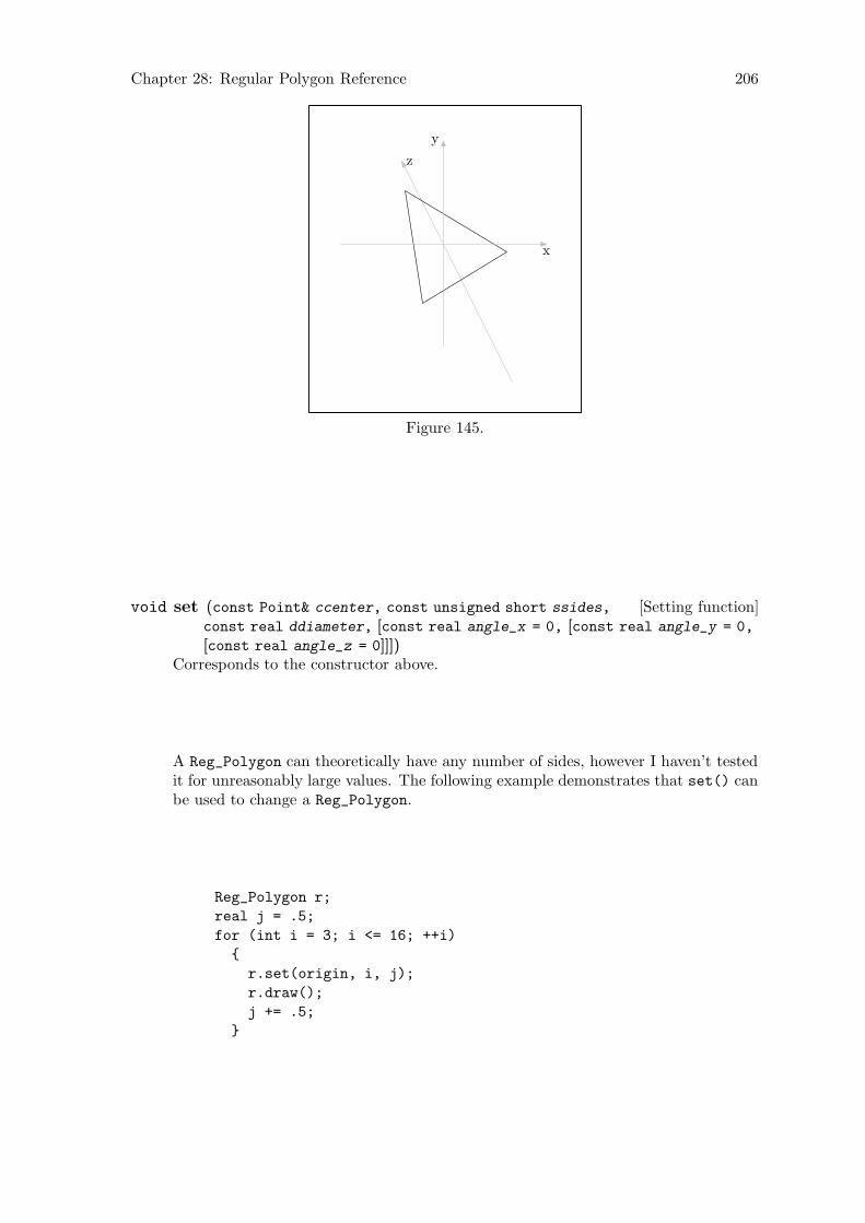
Chapter 28: Regular Polygon Reference 206
x
y
z
Figure 145.
[Setting function]void set (const Point& ccenter, const unsigned short ssides,
const real ddiameter, [const real angle_x = 0, [const real angle_y = 0,
[const real angle_z = 0]]])Corresponds to the constructor above.
A Reg_Polygon can theoretically have any number of sides, however I haven’t testedit for unreasonably large values. The following example demonstrates that set() canbe used to change a Reg_Polygon.
Reg_Polygon r;
real j = .5;
for (int i = 3; i <= 16; ++i)
{
r.set(origin, i, j);
r.draw();
j += .5;
}
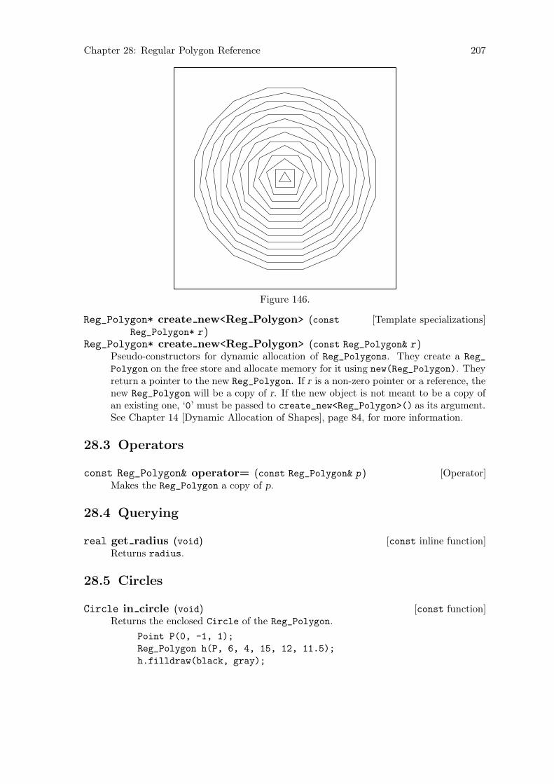
Chapter 28: Regular Polygon Reference 207
Figure 146.
[Template specializations]Reg_Polygon* create new<Reg Polygon> (constReg_Polygon* r )
Reg_Polygon* create new<Reg Polygon> (const Reg_Polygon& r )Pseudo-constructors for dynamic allocation of Reg_Polygons. They create a Reg_
Polygon on the free store and allocate memory for it using new(Reg_Polygon). Theyreturn a pointer to the new Reg_Polygon. If r is a non-zero pointer or a reference, thenew Reg_Polygon will be a copy of r. If the new object is not meant to be a copy ofan existing one, ‘0’ must be passed to create_new<Reg_Polygon>() as its argument.See Chapter 14 [Dynamic Allocation of Shapes], page 84, for more information.
28.3 Operators
[Operator]const Reg_Polygon& operator= (const Reg_Polygon& p )Makes the Reg_Polygon a copy of p.
28.4 Querying
[const inline function]real get radius (void)Returns radius.
28.5 Circles
[const function]Circle in circle (void)Returns the enclosed Circle of the Reg_Polygon.
Point P(0, -1, 1);
Reg_Polygon h(P, 6, 4, 15, 12, 11.5);
h.filldraw(black, gray);
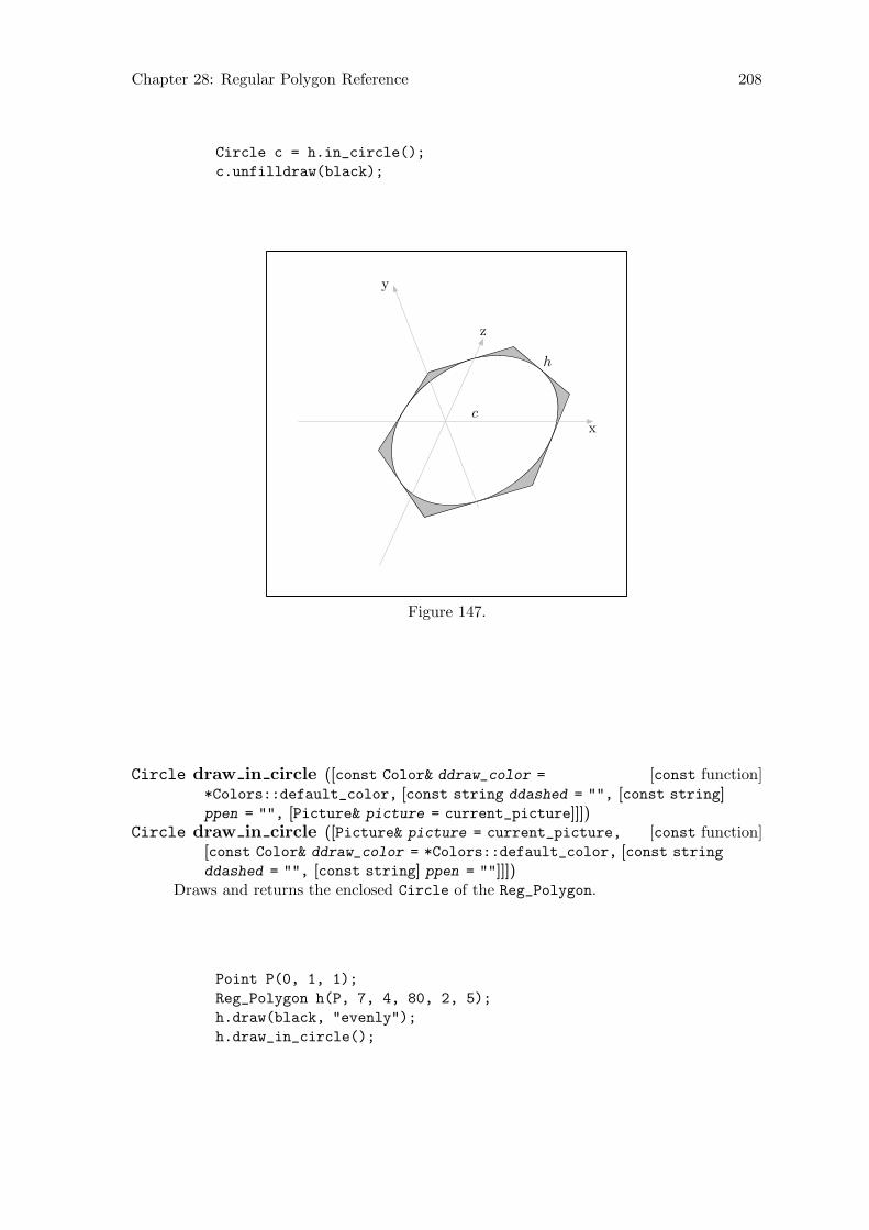
Chapter 28: Regular Polygon Reference 208
Circle c = h.in_circle();
c.unfilldraw(black);
h
cx
y
z
Figure 147.
[const function]Circle draw in circle ([const Color& ddraw_color =
*Colors::default_color, [const string ddashed = "", [const string]ppen = "", [Picture& picture = current_picture]]])
[const function]Circle draw in circle ([Picture& picture = current_picture,
[const Color& ddraw_color = *Colors::default_color, [const string
ddashed = "", [const string] ppen = ""]]])Draws and returns the enclosed Circle of the Reg_Polygon.
Point P(0, 1, 1);
Reg_Polygon h(P, 7, 4, 80, 2, 5);
h.draw(black, "evenly");
h.draw_in_circle();
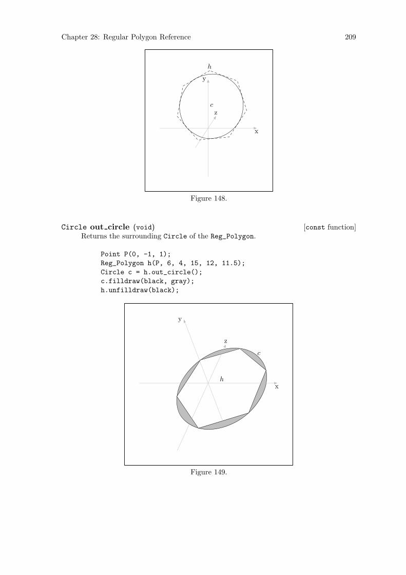
Chapter 28: Regular Polygon Reference 209
h
c
x
y
z
Figure 148.
[const function]Circle out circle (void)Returns the surrounding Circle of the Reg_Polygon.
Point P(0, -1, 1);
Reg_Polygon h(P, 6, 4, 15, 12, 11.5);
Circle c = h.out_circle();
c.filldraw(black, gray);
h.unfilldraw(black);
h
c
x
y
z
Figure 149.
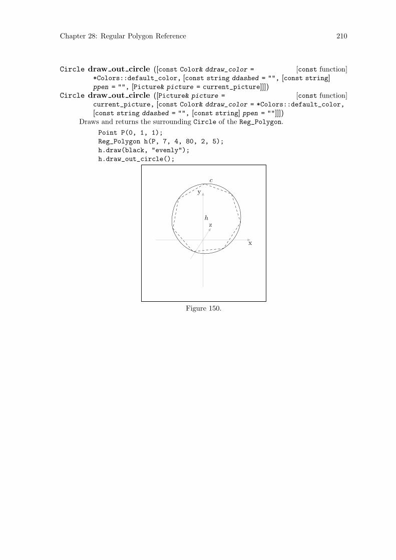
Chapter 28: Regular Polygon Reference 210
[const function]Circle draw out circle ([const Color& ddraw_color =
*Colors::default_color, [const string ddashed = "", [const string]ppen = "", [Picture& picture = current_picture]]])
[const function]Circle draw out circle ([Picture& picture =
current_picture, [const Color& ddraw_color = *Colors::default_color,
[const string ddashed = "", [const string] ppen = ""]]])Draws and returns the surrounding Circle of the Reg_Polygon.
Point P(0, 1, 1);
Reg_Polygon h(P, 7, 4, 80, 2, 5);
h.draw(black, "evenly");
h.draw_out_circle();
c
h
x
y
z
Figure 150.
Chapter 29: Rectangle Reference 211
29 Rectangle Reference
Class Rectangle is defined in ‘rectangs.web’, and is derived from Polygon, using publicderivation.
As noted above in Section 27.4 [Polygon Reference; Affine Transformations], page 200,class Rectangle, like class Reg_Polygon, currently inherits its transformation functionsand operator*=(const Transform&) from Polygon. Consequently, the data members of aRectangle, except for center, are not recalculated when it’s transformed. I plan to changethis soon! It will also be necessary to add the function Rectangle::is_rectangular(), inorder to test whether a Rectangle is still rectangular.
29.1 Data Members
[Private variables]real axis hreal axis v
The lengths of the horizontal and vertical axes, respectively, of the Rectangle. Ac-tually, they are merely the horizontal and vertical axes by convention, since there areno restrictions on the orientation of an Rectangle.
Please note that axis_h and axis_v are currently not recalculated, when a Rectangleis transformed. I plan to do something about this soon.
[Private variable]bool on free storetrue, if the Rectangle was dynamically allocated on the free store, otherwisefalse. Dynamic allocation of Rectangles should only be performed bycreate_new<Rectangle>(), which sets on_free_store to true.
29.2 Constructors and Setting Functions
[Default constructor]void Rectangle (void)Creates an empty Rectangle.
[Constructor]void Rectangle (const Point& ccenter, const real aaxis_h,
const real aaxis_v, [const real angle_x = 0, [const real angle_y = 0,
[const real angle_z = 0]]])Creates a Rectangle in the x-z plane, centered at the origin, with width ≡ aaxis h
(in the ±x direction), and height ≡ aaxis v (in the ±z direction). If one or more ofthe arguments angle x, angle y, or angle z are used, it is rotated by those amountsaround the appropriate axes. Finally, the Rectangle is shifted such that its centerlies at ccenter.
Point C(-1, -1, 1);
Rectangle r(C, 3, 4, 30, 30, 30);
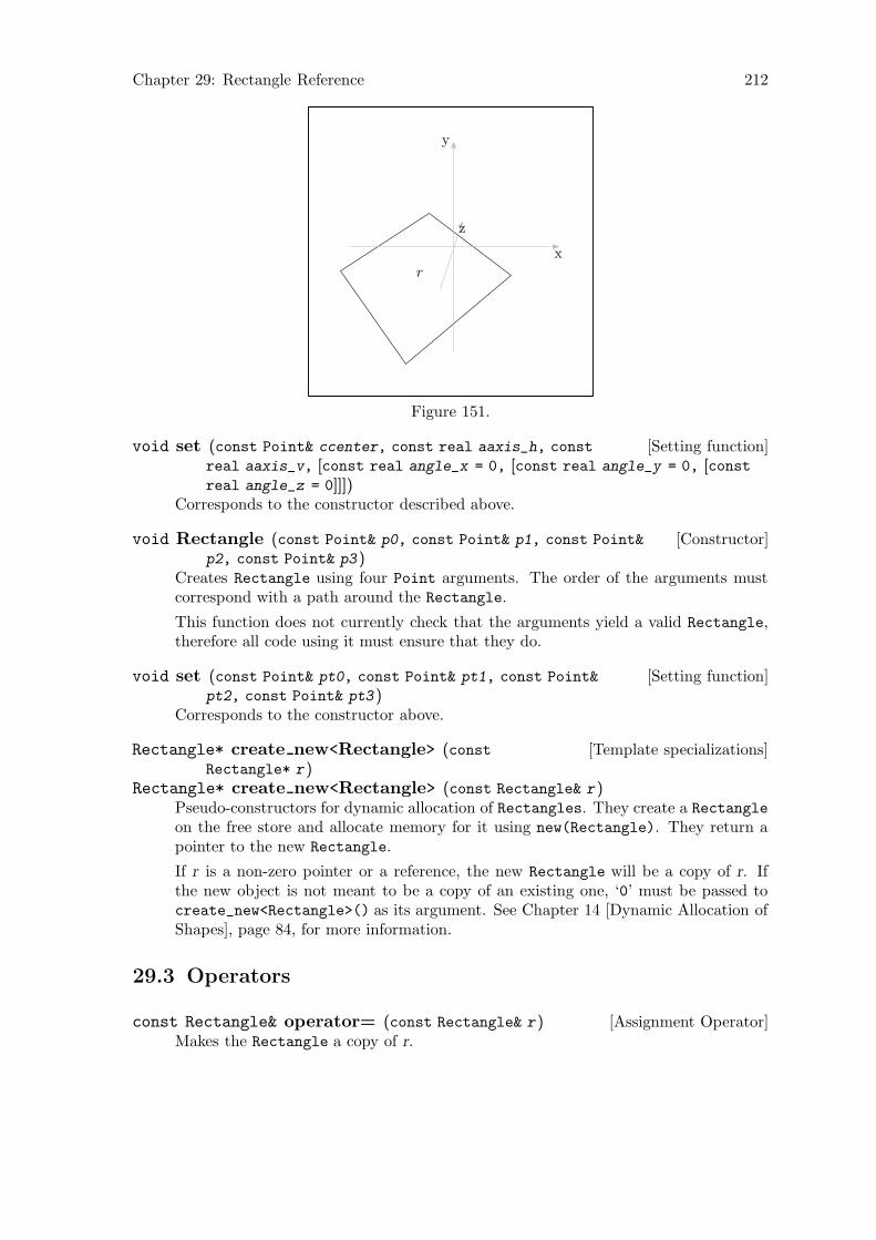
Chapter 29: Rectangle Reference 212
r
x
y
z
Figure 151.
[Setting function]void set (const Point& ccenter, const real aaxis_h, const
real aaxis_v, [const real angle_x = 0, [const real angle_y = 0, [constreal angle_z = 0]]])
Corresponds to the constructor described above.
[Constructor]void Rectangle (const Point& p0, const Point& p1, const Point&
p2, const Point& p3 )Creates Rectangle using four Point arguments. The order of the arguments mustcorrespond with a path around the Rectangle.
This function does not currently check that the arguments yield a valid Rectangle,therefore all code using it must ensure that they do.
[Setting function]void set (const Point& pt0, const Point& pt1, const Point&
pt2, const Point& pt3 )Corresponds to the constructor above.
[Template specializations]Rectangle* create new<Rectangle> (constRectangle* r )
Rectangle* create new<Rectangle> (const Rectangle& r )Pseudo-constructors for dynamic allocation of Rectangles. They create a Rectangle
on the free store and allocate memory for it using new(Rectangle). They return apointer to the new Rectangle.
If r is a non-zero pointer or a reference, the new Rectangle will be a copy of r. Ifthe new object is not meant to be a copy of an existing one, ‘0’ must be passed tocreate_new<Rectangle>() as its argument. See Chapter 14 [Dynamic Allocation ofShapes], page 84, for more information.
29.3 Operators
[Assignment Operator]const Rectangle& operator= (const Rectangle& r )Makes the Rectangle a copy of r.
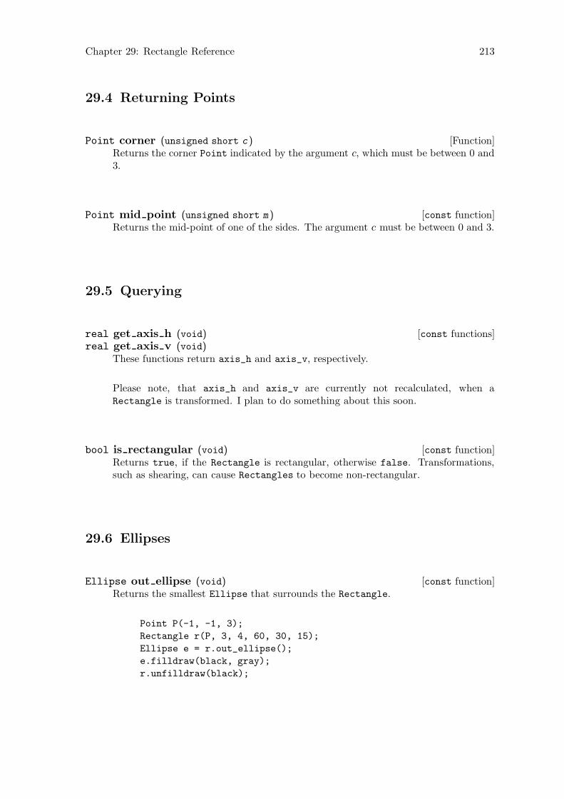
Chapter 29: Rectangle Reference 213
29.4 Returning Points
[Function]Point corner (unsigned short c )Returns the corner Point indicated by the argument c, which must be between 0 and3.
[const function]Point mid point (unsigned short m )Returns the mid-point of one of the sides. The argument c must be between 0 and 3.
29.5 Querying
[const functions]real get axis h (void)real get axis v (void)
These functions return axis_h and axis_v, respectively.
Please note, that axis_h and axis_v are currently not recalculated, when aRectangle is transformed. I plan to do something about this soon.
[const function]bool is rectangular (void)Returns true, if the Rectangle is rectangular, otherwise false. Transformations,such as shearing, can cause Rectangles to become non-rectangular.
29.6 Ellipses
[const function]Ellipse out ellipse (void)Returns the smallest Ellipse that surrounds the Rectangle.
Point P(-1, -1, 3);
Rectangle r(P, 3, 4, 60, 30, 15);
Ellipse e = r.out_ellipse();
e.filldraw(black, gray);
r.unfilldraw(black);
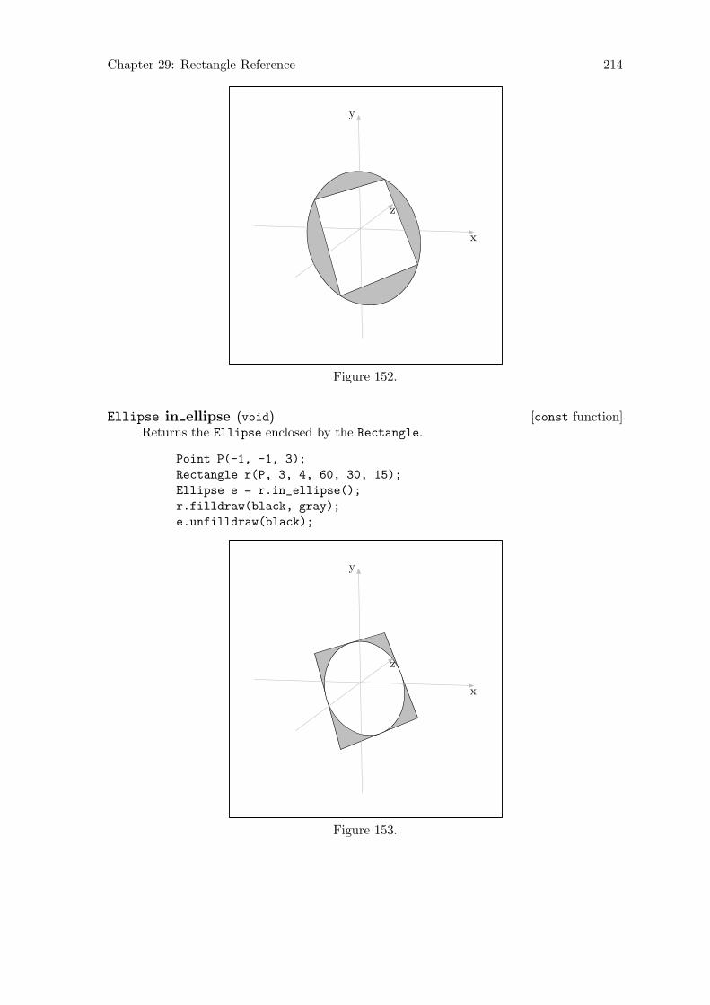
Chapter 29: Rectangle Reference 214
x
y
z
Figure 152.
[const function]Ellipse in ellipse (void)Returns the Ellipse enclosed by the Rectangle.
Point P(-1, -1, 3);
Rectangle r(P, 3, 4, 60, 30, 15);
Ellipse e = r.in_ellipse();
r.filldraw(black, gray);
e.unfilldraw(black);
x
y
z
Figure 153.

Chapter 29: Rectangle Reference 215
[const function]Ellipse draw out ellipse ([const Color& ddraw_color =
*Colors::default_color, [string ddashed = "", [string ppen = "",
[Picture& picture = current_picture]]]])Draws the smallest Ellipse that surrounds the Rectangle. The arguments are likethose of Path::draw() (see Section 26.12 [Path Reference; Drawing and Filling],page 180). The return value is the surrounding Ellipse.
[const function]Ellipse draw in ellipse ([const Color& ddraw_color =
*Colors::default_color, [string ddashed = "", [string ppen = "",
[Picture& picture = current_picture]]]])Draws the Ellipse enclosed by the Rectangle. The arguments are like those ofPath::draw() (see Section 26.12 [Path Reference; Drawing and Filling], page 180).The return value is the enclosed Ellipse.
Chapter 30: Regular Closed Plane Curve Reference 216
30 Regular Closed Plane Curve Reference
Class Reg_Cl_Plane_Curve is defined in ‘curves.web’. It is derived from Path using publicderivation.
Reg_Cl_Plane_Curve is not called “Regular_Closed_Plane_Curve” because the longername causes too many “Overfull boxes”1 in the CWEAVE output of the program code. SeeSection 1.3 [CWEB Documentation], page 5.
Reg_Cl_Plane_Curve is meant to be used as a base class; no objects should be declaredof type Reg_Cl_Plane_Curve. Currently, class Ellipses is derived from Reg_Cl_Plane_
Curve and class Circle is derived from Ellipse.
At present, I have no fixed definition of what constitutes “regularity” as far as Reg_
Cl_Plane_Curves are concerned. Ellipses and circles are “regular” in the sense that theyhave axes of symmetry. There must be an equation for a Reg_Cl_Plane_Curve, such asx2 + y2 = r2 for a circle. A derived class should have a solve() function that uses thisequation. Reg_Cl_Plane_Curve::intersection_points() in turn uses solve() to findthe intersection points of a line with the Reg_Cl_Plane_Curve. This way, the derivedclasses don’t need their own functions for finding their intersections with a line. However,such functions can be added, if desired.
It is assumed that classes derived from Reg_Cl_Plane_Curve are fillable, which impliesthat they must be closed Paths. Reg_Cl_Plane_Curves inherit their drawing and fillingfunctions from Path.
The constructors and setting functions of classes derived from Reg_Cl_Plane_Curve
must ensure that the resulting geometric figures are planar, convex, and that the numberof Points they contain is a multiple of 4. The latter assumption is of importance inintersection_points(), segment(), half(), and quarter(). See Section 30.3 [RegularClosed Plane Curve Reference; Intersections], page 217, and Section 30.4 [Regular ClosedPlane Curve Reference; Segments], page 219.
30.1 Data Members
[Protected variable]Point centerThe center of the Reg_Cl_Plane_Curve, if it has one.
[Protected variable]unsigned short number of pointsThe number of Points on points in a Reg_Cl_Plane_Curve.
30.2 Querying
[const inline virtual functions]bool is quadratic (void)bool is cubic (void)bool is quartic (void)
These functions all return false. They are intended to be overloaded by memberfunctions of derived classes.
1 If you don’t know what “overfull boxes” are, don’t worry about it. It has to do with TEX’s line and pagebreaking algorithms. If you want to know more, see Knuth, Donald E., The TEXbook.

Chapter 30: Regular Closed Plane Curve Reference 217
[const inline virtual function]real_triple get coefficients (real Slope, real
v_intercept )Returns a real_triple with all three values ≡ INVALID_REAL. Intended to be over-loaded by member functions of derived classes.
[const inline virtual function]pair<real, real> solve (char axis_unknown, real
known )Returns a pair<real, real> with first = second = INVALID_REAL. Intended tobe overloaded by member functions of derived classes.
[const virtual function]signed short location (Point ref_pt, Point p )Returns a signed short indicating the location of p with respect to the Reg_Cl_
Plane_Curve, which must be planar. The Reg_Cl_Plane_Curve constructors shouldensure that Reg_Cl_Plane_Curves are, but there is no guarantee that they will nothave been manipulated into a non-planar state, by shearing, for example.
The argument ref pt is used within the function for shifting a copy of the Reg_Cl_
Plane_Curve to a convenient position. It need not be the |center| of the Reg_Cl_
Plane_Curve, however, classes derived from Reg_Cl_Plane_Curve will probably havetheir own versions of location(), which will pass center as the ref pt argument tothis function. Reg_Cl_Plane_Curves need not have a meaningful |center|.
location() returns the following values:
-1 p and *this are coplanar, and p lies outside the perimeter of *this.
0 p and *this are coplanar, and p lies on the perimeter of *this.
1 p and *this are coplanar, and p lies inside the perimeter of *this.
-2 p and *this are not coplanar.
-3 Something has gone terribly wrong.
-4 The normal to *this has 0 magnitude, i.e., the |Points| on *this arecolinear.
-5 An error occurred in putting *this in one of the major planes.
[Virtual function]Point angle point (real angle )Returns INVALID_POINT. Intended to be overloaded by member functions of derivedclasses.
30.3 Intersections
[const function]bool_point_pair intersection points (Point ref_pt, Point
p0, Point p1 )[const function]bool_point_pair intersection points (const Point& ref_pt,
const Path& p )The version of this function taking Point arguments finds the intersection points,if any, of the Reg_Cl_Plane_Curve and the line p that passes through the Points
p0 and p1. In the other version, the Path argument must be a linear Path, and its
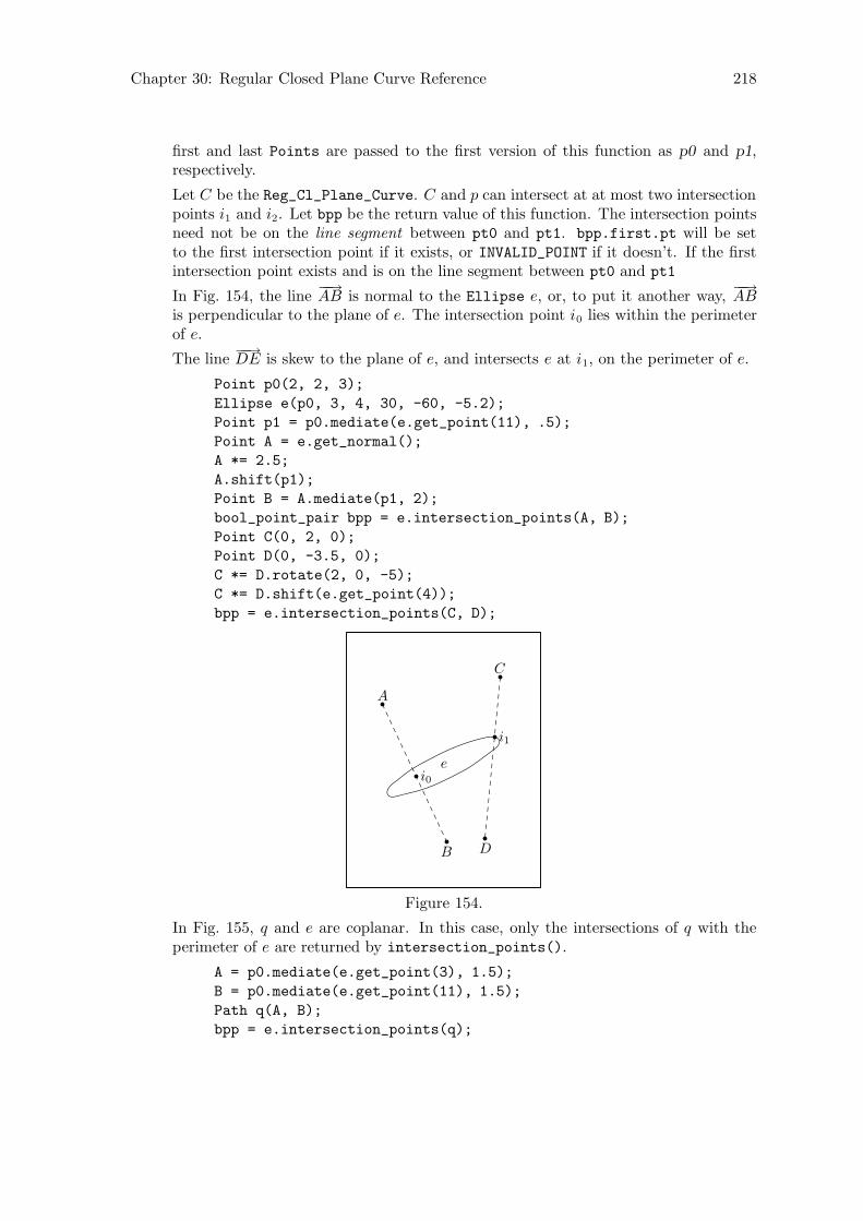
Chapter 30: Regular Closed Plane Curve Reference 218
first and last Points are passed to the first version of this function as p0 and p1,respectively.
Let C be the Reg_Cl_Plane_Curve. C and p can intersect at at most two intersectionpoints i1 and i2. Let bpp be the return value of this function. The intersection pointsneed not be on the line segment between pt0 and pt1. bpp.first.pt will be setto the first intersection point if it exists, or INVALID_POINT if it doesn’t. If the firstintersection point exists and is on the line segment between pt0 and pt1
In Fig. 154, the line−−→AB is normal to the Ellipse e, or, to put it another way,
−−→AB
is perpendicular to the plane of e. The intersection point i0 lies within the perimeterof e.
The line−−→DE is skew to the plane of e, and intersects e at i1, on the perimeter of e.
Point p0(2, 2, 3);
Ellipse e(p0, 3, 4, 30, -60, -5.2);
Point p1 = p0.mediate(e.get_point(11), .5);
Point A = e.get_normal();
A *= 2.5;
A.shift(p1);
Point B = A.mediate(p1, 2);
bool_point_pair bpp = e.intersection_points(A, B);
Point C(0, 2, 0);
Point D(0, -3.5, 0);
C *= D.rotate(2, 0, -5);
C *= D.shift(e.get_point(4));
bpp = e.intersection_points(C, D);
e
A
B
i0
C
D
i1
Figure 154.
In Fig. 155, q and e are coplanar. In this case, only the intersections of q with theperimeter of e are returned by intersection_points().
A = p0.mediate(e.get_point(3), 1.5);
B = p0.mediate(e.get_point(11), 1.5);
Path q(A, B);
bpp = e.intersection_points(q);
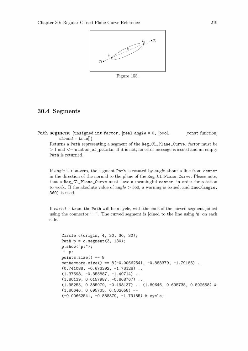
Chapter 30: Regular Closed Plane Curve Reference 219
e
q0
q1
i0
i1
Figure 155.
30.4 Segments
[const function]Path segment (unsigned int factor, [real angle = 0, [boolclosed = true]])
Returns a Path representing a segment of the Reg_Cl_Plane_Curve. factor must be> 1 and <= number_of_points. If it is not, an error message is issued and an emptyPath is returned.
If angle is non-zero, the segment Path is rotated by angle about a line from center
in the direction of the normal to the plane of the Reg_Cl_Plane_Curve. Please note,that a Reg_Cl_Plane_Curve must have a meaningful center, in order for rotationto work. If the absolute value of angle > 360, a warning is issued, and fmod(angle,
360) is used.
If closed is true, the Path will be a cycle, with the ends of the curved segment joinedusing the connector ‘--’. The curved segment is joined to the line using ‘&’ on eachside.
Circle c(origin, 4, 30, 30, 30);
Path p = c.segment(3, 130);
p.show("p:");
a p:
points.size() == 8
connectors.size() == 8(-0.00662541, -0.888379, -1.79185) ..
(0.741088, -0.673392, -1.73128) ..
(1.37598, -0.355887, -1.40714) ..
(1.80139, 0.0157987, -0.868767) ..
(1.95255, 0.385079, -0.198137) .. (1.80646, 0.695735, 0.502658) &
(1.80646, 0.695735, 0.502658) --
(-0.00662541, -0.888379, -1.79185) & cycle;
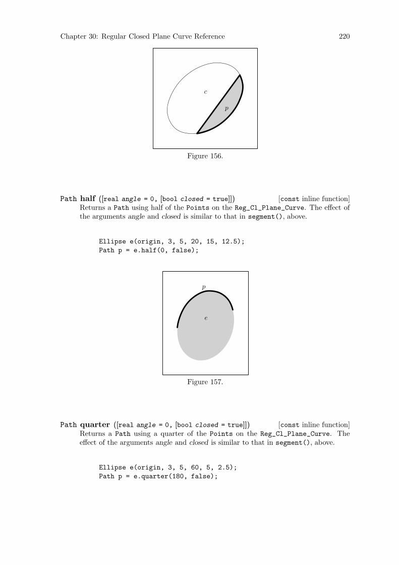
Chapter 30: Regular Closed Plane Curve Reference 220
c
p
Figure 156.
[const inline function]Path half ([real angle = 0, [bool closed = true]])Returns a Path using half of the Points on the Reg_Cl_Plane_Curve. The effect ofthe arguments angle and closed is similar to that in segment(), above.
Ellipse e(origin, 3, 5, 20, 15, 12.5);
Path p = e.half(0, false);
e
p
Figure 157.
[const inline function]Path quarter ([real angle = 0, [bool closed = true]])Returns a Path using a quarter of the Points on the Reg_Cl_Plane_Curve. Theeffect of the arguments angle and closed is similar to that in segment(), above.
Ellipse e(origin, 3, 5, 60, 5, 2.5);
Path p = e.quarter(180, false);

Chapter 30: Regular Closed Plane Curve Reference 221
e
p
Figure 158.

Chapter 31: Ellipse Reference 222
31 Ellipse Reference
Class Ellipse is defined in ‘ellipses.web’. It is derived from Reg_Cl_Plane_Curve usingpublic derivation.
31.1 Data Members
[Protected variables]Point focus0Point focus1
The foci of the Ellipse. They are located on the major axis of the Ellipse at adistance of linear_eccentricity from center, on opposite sides of the minor axis.
[Protected variable]real linear eccentricity
The linear eccentricity of the Ellipse e, such that e =√
a2 − b2, where a and b are
half the lengths of the major and minor axes, respectively. Let h stand for axis_h
and v for axis_v. If h > v, then a = h/2 and b = v/2. If v > h, then a = v/2 andb = h/2. If h = v, then the Ellipse is circular (but not an object of type Circle!),and a = b = v/2 = h/2.
The linear eccentricity is the distance along the major axis of the Ellipse fromcenter to focus0 and focus1.
[Protected variable]real numerical eccentricityThe numerical eccentricity ε of the Ellipse, such that ε = e/a < 1, where e is thelinear eccentricity of the Ellipse, and a is half the length of the major axis of theEllipse.
[Protected variables]real axis hreal axis v
The horizontal and vertical axes, respectively, of the Ellipse.
Actually, they are only or vertical horizontal by convention, since there are no restric-tions on the orientation of an Ellipse.
[Protected static variable]unsigned shortDEFAULT NUMBER OF POINTS
The number of Points on an Ellipse, unless another number is specified when anEllipse constructor is invoked.
31.2 Constructors and Setting Functions
[Default constructor]void Ellipse (void)Creates an empty Ellipse.
[Constructor]void Ellipse (const Point& ccenter, const real aaxis_h, const
real aaxis_v, [const real angle_x = 0, [const real angle_y = 0, [constreal angle_z = 0, [const unsigned short nnumber_of_points =
DEFAULT_NUMBER_OF_POINTS]]]])Creates an Ellipse in the x-z plane, centered at the origin, with its horizontal axis
≡ aaxis h and its vertical axis ≡ aaxis v. If any of the arguments angle x, angle y,

Chapter 31: Ellipse Reference 223
or angle z is non-zero, the Ellipse is rotated about the x, y, and z-axis in that order,by the amounts indicated by the corresponding arguments. Finally, the Ellipse isshifted such that its center comes to lie at ccenter.
Ellipse e(origin, 6, 4);
e.draw();
x
z
Figure 159.
Point P(1, 1, 1);
Ellipse e(P, 6, 4, 15, 12, 11);
e.draw();
x
y
z
Figure 160.
Chapter 31: Ellipse Reference 224
[Setting function]void set (const Point& ccenter, const real aaxis_h, const
real aaxis_v, [const real angle_x = 0, [const real angle_y = 0, [constreal angle_z = 0, [const unsigned short nnumber_of_points =
DEFAULT_NUMBER_OF_POINTS]]]])Corresponds to the constructor above.
[Template specializations]Ellipse* create new<Ellipse> (const Ellipse* e )Ellipse* create new<Ellipse> (const Ellipse& e )
Pseudo-constructors for dynamic allocation of Ellipses. They create a Ellipse onthe free store and allocate memory for it using new(Ellipse). They return a pointerto the new Ellipse.
If e is a non-zero pointer or a reference, the new Ellipse will be a copy of e. Ifthe new object is not meant to be a copy of an existing one, ‘0’ must be passed tocreate_new<Ellipse>() as its argument. See Chapter 14 [Dynamic Allocation ofShapes], page 84, for more information.
31.3 Performing Transformations
[Virtual function]Transform do transform (const Transform& t, [bool check =
false])Performs a transformation on an Ellipse. The Points on the Ellipse are multipliedby t. Then, if check is true, is_elliptical() is called on the Ellipse. If thetransformation has caused it to become non-elliptical, axis_h and axis_v are set toINVALID_REAL, and a warning is issued to stderr. center, focus0, and focus1 arenot set to INVALID_POINT. They may may no longer really be the center and foci ofthe (non-elliptical) Ellipse, but they may have some use for the programmer and/oruser.
If check is true, and the transformation does not cause *this to becomenon-elliptical, axis_h, axis_v, linear_eccentricity, numerical_eccentricity,focus0, and focus1 are recalculated.
31.4 Operators
[Assignment operator]Ellipse& operator= (const Ellipse& e )Makes the Ellipse a copy of e.
[Virtual function]Transform operator*= (const Transform& t )Calls do_transform(t, true), and returns the latter’s return value. See Section 31.3[Ellipse Reference; Performing Transformations], page 224.
31.5 Labeling
[const function]void label ([const string pos = "top", [const bool dot =
false, [Picture& picture = current_picture]]])Labels the Points on points, using lowercase letters. pos is used to position all ofthe labels. It is currently not possible to have different positions for the labels.
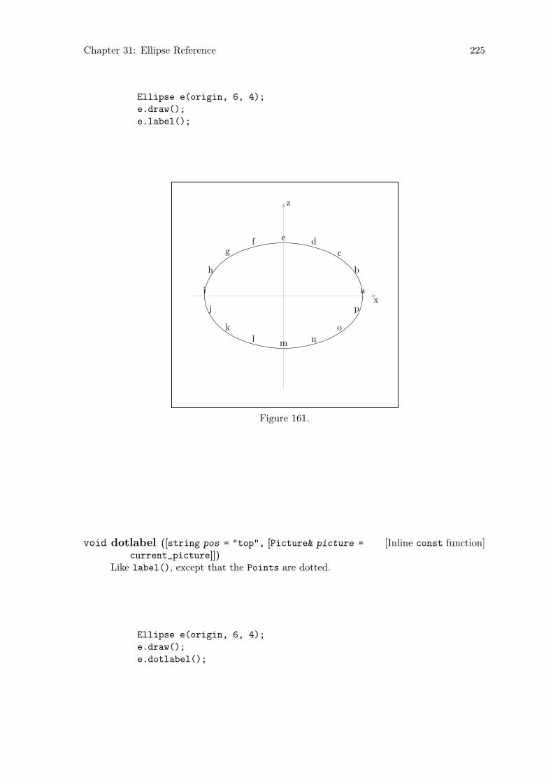
Chapter 31: Ellipse Reference 225
Ellipse e(origin, 6, 4);
e.draw();
e.label();
a
b
cdef
g
h
i
j
kl m n
o
px
z
Figure 161.
[Inline const function]void dotlabel ([string pos = "top", [Picture& picture =
current_picture]])Like label(), except that the Points are dotted.
Ellipse e(origin, 6, 4);
e.draw();
e.dotlabel();

Chapter 31: Ellipse Reference 226
a
b
cdef
g
h
i
j
kl m n
o
px
z
Figure 162.
31.6 Affine Transformations
[Virtual function]Transform rotate (const real x, [const real y = 0, [constreal z = 0]])
[Virtual function]Transform rotate (const Point& p0, const Point& p1, [constreal angle = 180])
[Virtual function]Transform rotate (const Path& p, [const real angle = 180])[Virtual function]Transform scale (real x, [real y = 1, [real z = 1]])[Virtual function]Transform shear (real xy, [real xz = 0, [real yx = 0, [real
yz = 0, [real zx = 0, [real zy = 0]]]]])[Virtual function]Transform shift (real x, [real y = 0, [real z = 0]])[Virtual function]Transform shift (const Point& p )[Virtual function]void shift times (real x, [real y = 1, [real z = 1]])[Virtual function]void shift times (const Point& p )
These create a Transform t locally, and call do_transform(t). See Section 31.3[Ellipse Reference; Performing Transformations], page 224.
Rotating and shifting an Ellipse neither change the size of an Ellipse, nor cause itto become non-elliptical. However, scaling and shearing can have these effects. Forthis reason, in scale() and shear(), do_transform() is called with true as its check
argument, while it is false in rotate(), shift(), and shift_times().
If scaling or shearing is performed on an Ellipse, and it is still elliptical afterthe transformation, focus0, focus1, axis_h, axis_v, linear_eccentricity, andnumerical_eccentricity are all recalculated. If the Ellipse is non-elliptical af-ter the transformation, axis_h, axis_v, linear_eccentricity, and numerical_
eccentricity are all set to INVALID_REAL. center, focus0, and focus1 are not setto INVALID_POINT. Although they are no longer the center and foci of an ellipticalEllipse, they may still have some use for the user or programmer.
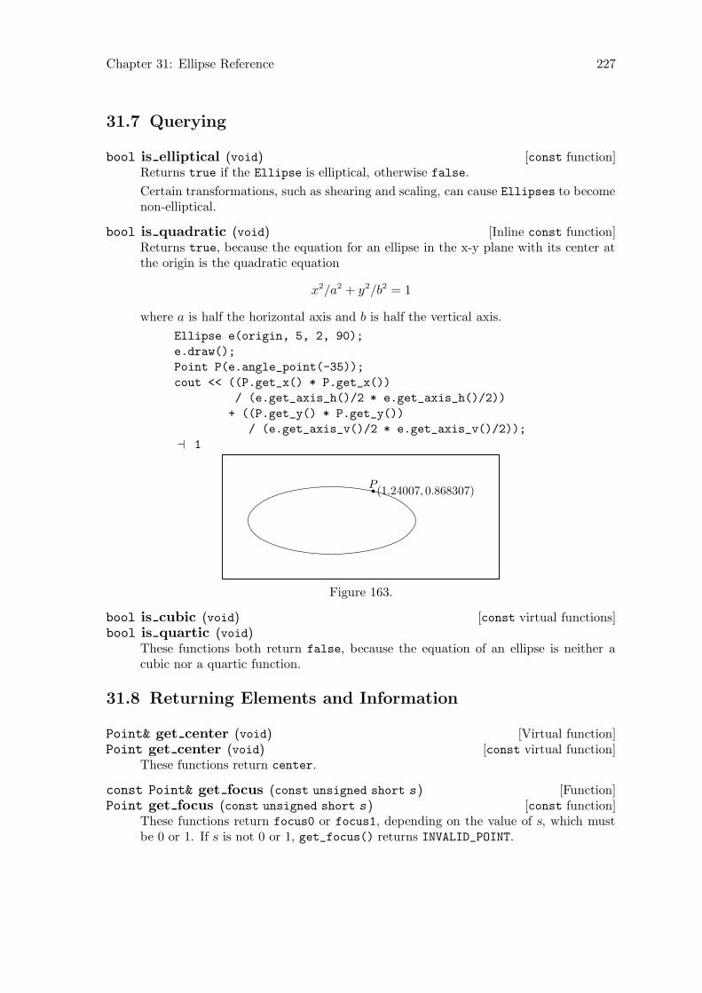
Chapter 31: Ellipse Reference 227
31.7 Querying
[const function]bool is elliptical (void)Returns true if the Ellipse is elliptical, otherwise false.
Certain transformations, such as shearing and scaling, can cause Ellipses to becomenon-elliptical.
[Inline const function]bool is quadratic (void)Returns true, because the equation for an ellipse in the x-y plane with its center atthe origin is the quadratic equation
x2/a2 + y2/b2 = 1
where a is half the horizontal axis and b is half the vertical axis.
Ellipse e(origin, 5, 2, 90);
e.draw();
Point P(e.angle_point(-35));
cout << ((P.get_x() * P.get_x())
/ (e.get_axis_h()/2 * e.get_axis_h()/2))
+ ((P.get_y() * P.get_y())
/ (e.get_axis_v()/2 * e.get_axis_v()/2));
a 1
P(1.24007, 0.868307)
Figure 163.
[const virtual functions]bool is cubic (void)bool is quartic (void)
These functions both return false, because the equation of an ellipse is neither acubic nor a quartic function.
31.8 Returning Elements and Information
[Virtual function]Point& get center (void)[const virtual function]Point get center (void)
These functions return center.
[Function]const Point& get focus (const unsigned short s )[const function]Point get focus (const unsigned short s )
These functions return focus0 or focus1, depending on the value of s, which mustbe 0 or 1. If s is not 0 or 1, get_focus() returns INVALID_POINT.
Chapter 31: Ellipse Reference 228
[const function]real get linear eccentricity (void)Returns linear_eccentricity.
[const function]real get numerical eccentricity (void)Returns numerical_eccentricity.
[Function]real get axis v (void)[const function]real get axis v (void)
Calculates and returns the value of axis_h.
get_axis_v() first checks if the Ellipse is still elliptical, using is_elliptical()
(see Section 31.7 [Ellipse Reference; Querying], page 227). Operations such asscale() and shear() can cause an Ellipse to become non-elliptical. If this is thecase, this function returns INVALID_REAL.
If the Ellipse is still elliptical, axis_v is recalculated and returned. In the non-constversion, axis_v is also reset to the new value.
[Function]real get axis h (void)[const function]real get axis h (void)
Calculates and returns the value of axis_h.
get_axis_h() first checks if the Ellipse is still elliptical, using is_elliptical()
(see Section 31.7 [Ellipse Reference; Querying], page 227). Operations such asscale() and shear() can cause an Ellipse to become non-elliptical. If this is thecase, this function returns INVALID_REAL.
If the Ellipse is still elliptical, axis_h is recalculated and returned. In the non-constversion, axis_h is also reset to the new value.
[const virtual function]signed short location (Point p )Returns a value l indicating the location of the Point argument p with respect to theEllipse.
Let e stand for the Ellipse. The return values are as follows:
0 p lies on the perimeter of e.
1 p lies in the plane of e, within its perimeter.
-1 p lies in the plane of e, outside its perimeter.
-2 p and e do not lie in the same plane.
-3 e is not elliptical, possibly due to having been transformed.
Ellipse e(origin, 3, 5, 45, 15, 3);
e.shift(2, 1, 1);
Point A = e.get_point(7);
cout << e.location(A);
a 0
Point B = center.mediate(e.get_point(2));
cout << e.location(B);
a 1
Point C = center.mediate(e.get_point(2), 1.5);
cout << e.location(C);
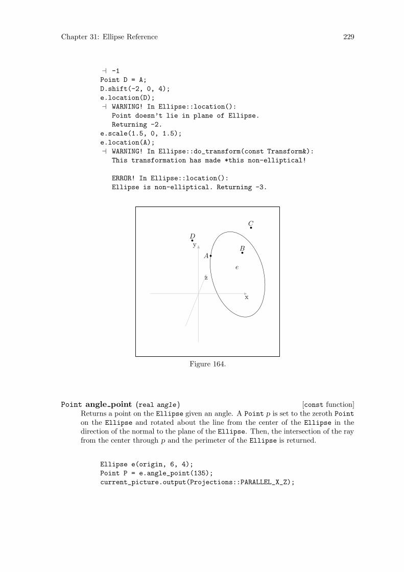
Chapter 31: Ellipse Reference 229
a -1
Point D = A;
D.shift(-2, 0, 4);
e.location(D);
a WARNING! In Ellipse::location():
Point doesn’t lie in plane of Ellipse.
Returning -2.
e.scale(1.5, 0, 1.5);
e.location(A);
a WARNING! In Ellipse::do_transform(const Transform&):
This transformation has made *this non-elliptical!
ERROR! In Ellipse::location():
Ellipse is non-elliptical. Returning -3.
e
AB
C
D
x
y
z
Figure 164.
[const function]Point angle point (real angle )Returns a point on the Ellipse given an angle. A Point p is set to the zeroth Point
on the Ellipse and rotated about the line from the center of the Ellipse in thedirection of the normal to the plane of the Ellipse. Then, the intersection of the rayfrom the center through p and the perimeter of the Ellipse is returned.
Ellipse e(origin, 6, 4);
Point P = e.angle_point(135);
current_picture.output(Projections::PARALLEL_X_Z);
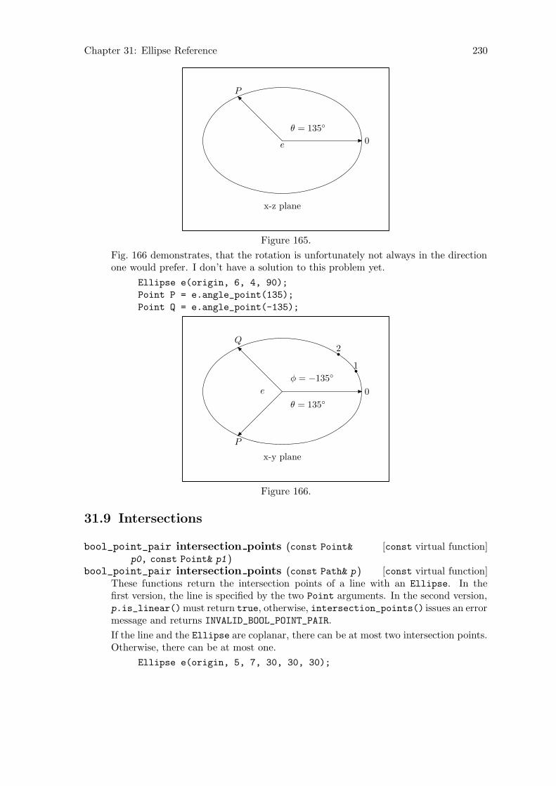
Chapter 31: Ellipse Reference 230
e 0
θ = 135◦
P
x-z plane
Figure 165.
Fig. 166 demonstrates, that the rotation is unfortunately not always in the directionone would prefer. I don’t have a solution to this problem yet.
Ellipse e(origin, 6, 4, 90);
Point P = e.angle_point(135);
Point Q = e.angle_point(-135);
e 0
1
2
θ = 135◦
P
φ = −135◦
Q
x-y plane
Figure 166.
31.9 Intersections
[const virtual function]bool_point_pair intersection points (const Point&
p0, const Point& p1 )[const virtual function]bool_point_pair intersection points (const Path& p )
These functions return the intersection points of a line with an Ellipse. In thefirst version, the line is specified by the two Point arguments. In the second version,p.is_linear()must return true, otherwise, intersection_points() issues an errormessage and returns INVALID_BOOL_POINT_PAIR.
If the line and the Ellipse are coplanar, there can be at most two intersection points.Otherwise, there can be at most one.
Ellipse e(origin, 5, 7, 30, 30, 30);
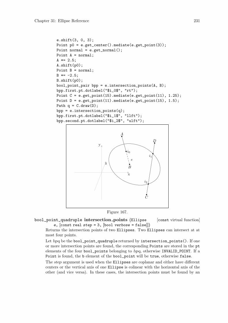
Chapter 31: Ellipse Reference 231
e.shift(3, 0, 3);
Point p0 = e.get_center().mediate(e.get_point(3));
Point normal = e.get_normal();
Point A = normal;
A *= 2.5;
A.shift(p0);
Point B = normal;
B *= -2.5;
B.shift(p0);
bool_point_pair bpp = e.intersection_points(A, B);
bpp.first.pt.dotlabel("$i_0$", "rt");
Point C = e.get_point(15).mediate(e.get_point(11), 1.25);
Point D = e.get_point(11).mediate(e.get_point(15), 1.5);
Path q = C.draw(D);
bpp = e.intersection_points(q);
bpp.first.pt.dotlabel("$i_1$", "llft");
bpp.second.pt.dotlabel("$i_2$", "ulft");
e
A
B
i0
C
D
i1
i2
x
y
z
Figure 167.
[const virtual function]bool_point_quadruple intersection points (Ellipsee, [const real step = 3, [bool verbose = false]])
Returns the intersection points of two Ellipses. Two Ellipses can intersect at atmost four points.
Let bpq be the bool_point_quadruple returned by intersection_points(). If oneor more intersection points are found, the corresponding Points are stored in the pt
elements of the four bool_points belonging to bpq, otherwise INVALID_POINT. If aPoint is found, the b element of the bool_point will be true, otherwise false.
The step argument is used when the Ellipses are coplanar and either have differentcenters or the vertical axis of one Ellipse is colinear with the horizontal axis of theother (and vice versa). In these cases, the intersection points must be found by an
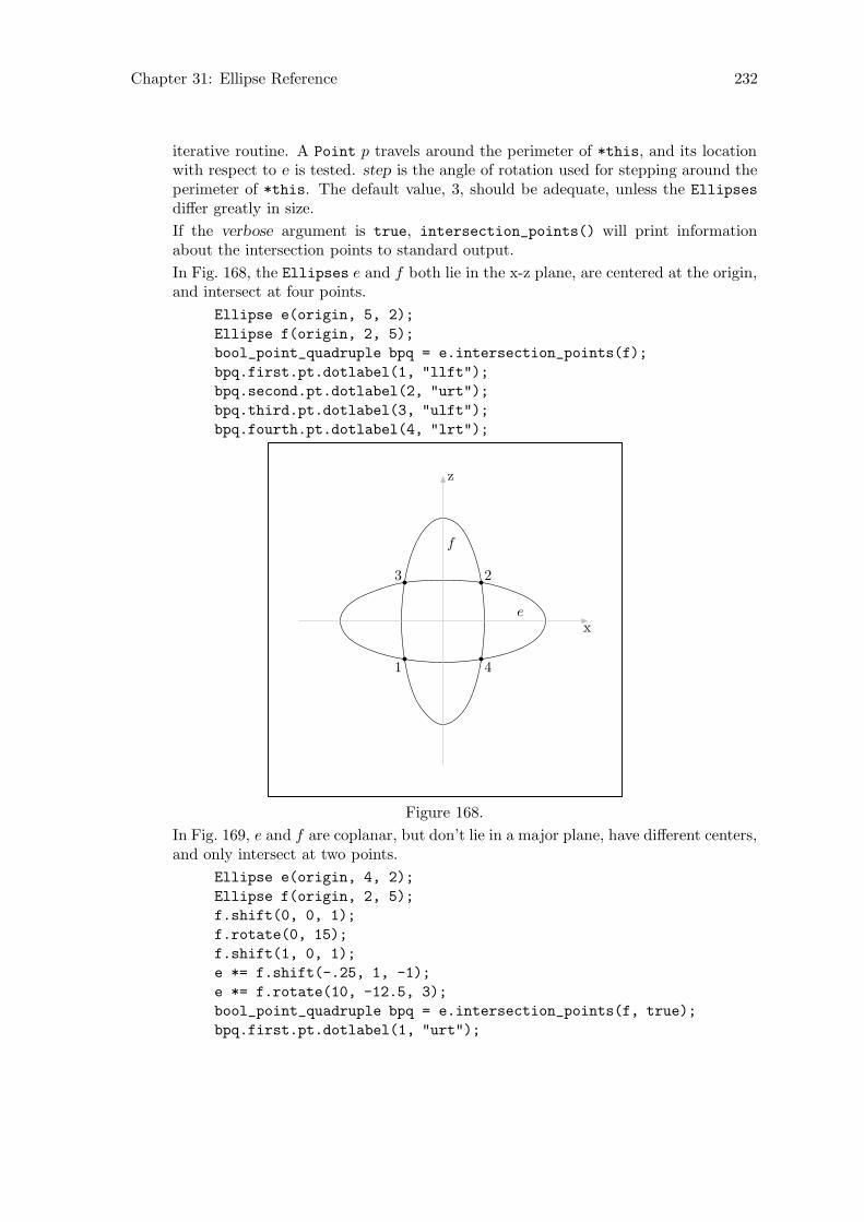
Chapter 31: Ellipse Reference 232
iterative routine. A Point p travels around the perimeter of *this, and its locationwith respect to e is tested. step is the angle of rotation used for stepping around theperimeter of *this. The default value, 3, should be adequate, unless the Ellipses
differ greatly in size.
If the verbose argument is true, intersection_points() will print informationabout the intersection points to standard output.
In Fig. 168, the Ellipses e and f both lie in the x-z plane, are centered at the origin,and intersect at four points.
Ellipse e(origin, 5, 2);
Ellipse f(origin, 2, 5);
bool_point_quadruple bpq = e.intersection_points(f);
bpq.first.pt.dotlabel(1, "llft");
bpq.second.pt.dotlabel(2, "urt");
bpq.third.pt.dotlabel(3, "ulft");
bpq.fourth.pt.dotlabel(4, "lrt");
e
f
1
23
4
x
z
Figure 168.
In Fig. 169, e and f are coplanar, but don’t lie in a major plane, have different centers,and only intersect at two points.
Ellipse e(origin, 4, 2);
Ellipse f(origin, 2, 5);
f.shift(0, 0, 1);
f.rotate(0, 15);
f.shift(1, 0, 1);
e *= f.shift(-.25, 1, -1);
e *= f.rotate(10, -12.5, 3);
bool_point_quadruple bpq = e.intersection_points(f, true);
bpq.first.pt.dotlabel(1, "urt");
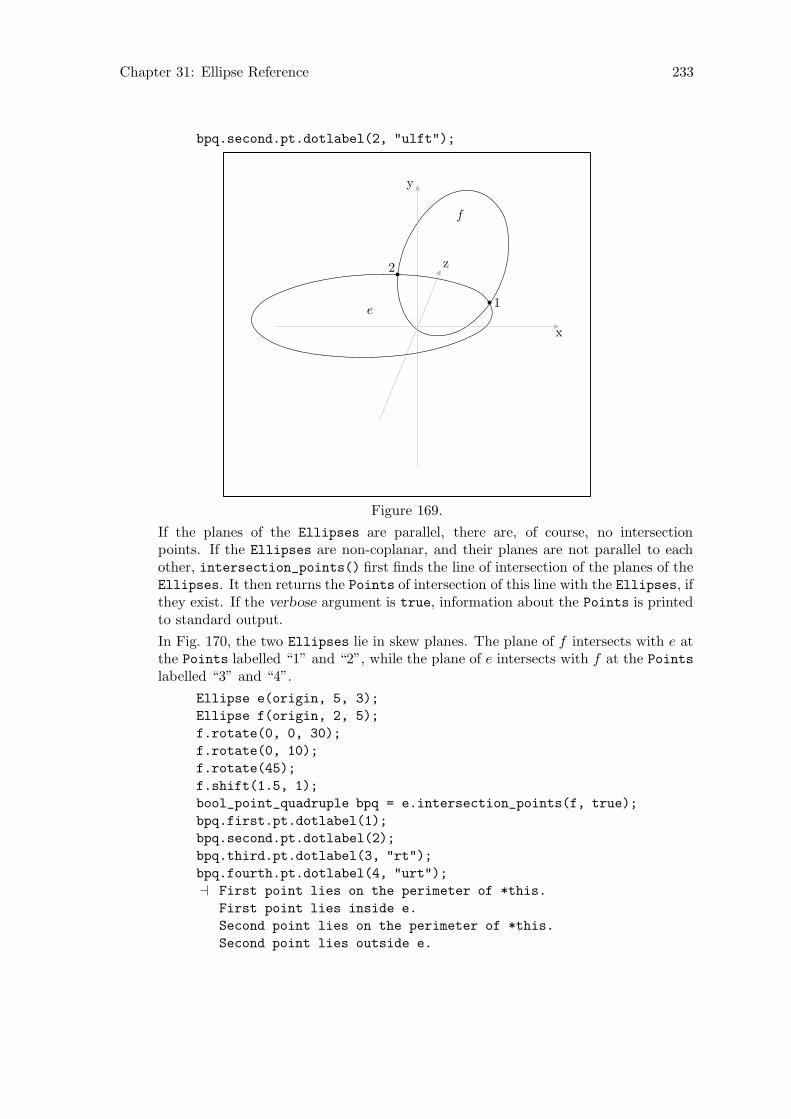
Chapter 31: Ellipse Reference 233
bpq.second.pt.dotlabel(2, "ulft");
e
f
1
2
x
y
z
Figure 169.
If the planes of the Ellipses are parallel, there are, of course, no intersectionpoints. If the Ellipses are non-coplanar, and their planes are not parallel to eachother, intersection_points() first finds the line of intersection of the planes of theEllipses. It then returns the Points of intersection of this line with the Ellipses, ifthey exist. If the verbose argument is true, information about the Points is printedto standard output.
In Fig. 170, the two Ellipses lie in skew planes. The plane of f intersects with e atthe Points labelled “1” and “2”, while the plane of e intersects with f at the Points
labelled “3” and “4”.
Ellipse e(origin, 5, 3);
Ellipse f(origin, 2, 5);
f.rotate(0, 0, 30);
f.rotate(0, 10);
f.rotate(45);
f.shift(1.5, 1);
bool_point_quadruple bpq = e.intersection_points(f, true);
bpq.first.pt.dotlabel(1);
bpq.second.pt.dotlabel(2);
bpq.third.pt.dotlabel(3, "rt");
bpq.fourth.pt.dotlabel(4, "urt");
a First point lies on the perimeter of *this.
First point lies inside e.
Second point lies on the perimeter of *this.
Second point lies outside e.
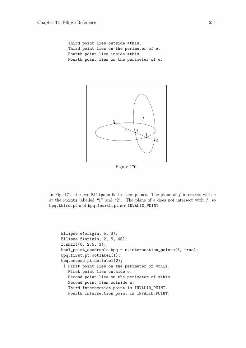
Chapter 31: Ellipse Reference 234
Third point lies outside *this.
Third point lies on the perimeter of e.
Fourth point lies inside *this.
Fourth point lies on the perimeter of e.
1
2
3
4e
f
Figure 170.
In Fig. 171, the two Ellipses lie in skew planes. The plane of f intersects with eat the Points labelled “1” and “2”. The plane of e does not intersect with f , sobpq.third.pt and bpq.fourth.pt are INVALID_POINT.
Ellipse e(origin, 5, 3);
Ellipse f(origin, 2, 5, 45);
f.shift(0, 2.5, 3);
bool_point_quadruple bpq = e.intersection_points(f, true);
bpq.first.pt.dotlabel(1);
bpq.second.pt.dotlabel(2);
a First point lies on the perimeter of *this.
First point lies outside e.
Second point lies on the perimeter of *this.
Second point lies outside e.
Third intersection point is INVALID_POINT.
Fourth intersection point is INVALID_POINT.

Chapter 31: Ellipse Reference 235
12e
f
Figure 171.
31.10 Solving
[const function]real_pair solve (char axis_unknown, real known )Returns two possible values for either the horizontal or vertical coordinate. Thisfunction assumes that the Ellipse lies in a major plane with center at the origin.Code that calls it must ensure that these conditions are fulfilled.
solve() is called in Reg_Cl_Plane_Curve::intersection_points(Point, Point,
Point) and Reg_Cl_Plane_Curve::location(), and resolves to this function, whenthese functions are called on an Ellipse. However, Ellipse::location() over-loads Reg_Cl_Plane_Curve::location(), so the latter won’t normally be calledon an Ellipse. See Section 30.3 [Regular Closed Plane Curve Reference; Intersec-tions], page 217, and Section 30.2 [Regular Closed Plane Curve Reference; Querying],page 216.
[const function]real_triple get coefficients (real Slope, real v_intercept )Let x and y stand for the x and y-coordinates of a point on an ellipse in the x-yplane, a for half of the horizontal axis (axis_h/2), and b for half of the vertical axis(axis_v/2).
Further, let y = mx + i be the equation of a line in the x-y plane, where m is theslope and i the y-intercept.
This function returns the coefficients of the quadratic equation that results fromreplacing y with mx + i in the equation for the ellipse
x2/a2 + y2/b2 = 1
namelyx2/a2 + (mx + i)2/b2 − 1 = 0
≡ (b2x + a2m2)x2 + 2a2imx + (a2i2 − a2b2) = 0.
The coefficients are returned in the real_triple in the order one would expect:r.first is the coefficient of x2, r.second of x and r.third of the constant term(x0 ≡ 1).
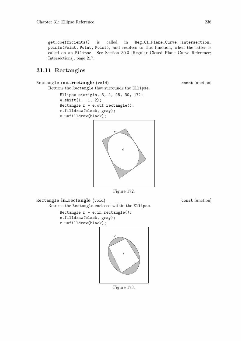
Chapter 31: Ellipse Reference 236
get_coefficients() is called in Reg_Cl_Plane_Curve::intersection_
points(Point, Point, Point), and resolves to this function, when the latter iscalled on an Ellipse. See Section 30.3 [Regular Closed Plane Curve Reference;Intersections], page 217.
31.11 Rectangles
[const function]Rectangle out rectangle (void)Returns the Rectangle that surrounds the Ellipse.
Ellipse e(origin, 3, 4, 45, 30, 17);
e.shift(1, -1, 2);
Rectangle r = e.out_rectangle();
r.filldraw(black, gray);
e.unfilldraw(black);
e
r
Figure 172.
[const function]Rectangle in rectangle (void)Returns the Rectangle enclosed within the Ellipse.
Rectangle r = e.in_rectangle();
e.filldraw(black, gray);
r.unfilldraw(black);
e
r
Figure 173.

Chapter 31: Ellipse Reference 237
[const function]Rectangle draw out rectangle ([const Color& ddraw_color =
*Colors::default_color, [string ddashed = "", [string ppen = "",
[Picture& picture = current_picture]]]])Draws the Rectangle that surrounds the Ellipse. The arguments are like those ofPath::draw(). The return value is the surrounding Rectangle. See Section 26.12[Path Reference; Drawing and Filling], page 180.
Ellipse e(origin, 2.5, 5, 10, 12, 15.5);
e.shift(-1, 1, 1);
e.draw_out_rectangle(black, "evenly", "pencircle scaled .3mm");
e
r
Figure 174.
[const function]Rectangle draw in rectangle ([const Color& ddraw_color =
*Colors::default_color, [string ddashed = "", [string ppen = "",
[Picture& picture = current_picture]]]])Draws the Rectangle enclosed within the Ellipse. The arguments are like those ofPath::draw(). The return value is the enclosed Rectangle. See Section 26.12 [PathReference; Drawing and Filling], page 180.
Ellipse e(origin, 3.5, 6, 10, 12, 15.5);
e.shift(-1, 1, 1);
e.draw_in_rectangle(black, "evenly", "pencircle scaled .3mm");
r
e
Figure 175.
Chapter 32: Circle Reference 238
32 Circle Reference
Class Circle is defined in ‘circles.web’. It is derived from Ellipse, using public deriva-tion.
Since Circle is just a special kind of Ellipse, there is often no need to define specialfunctions for Circles.
Currently, Circle inherits the transformation functions and operator*=(const
Transform&) from Ellipse. Consequently, the data member radius, described below, isnot recalculated, when transformations are performed on a Circle. I plan to change thissoon!
32.1 Data Members
[Private variable]real radiusThe radius of the Circle.
32.2 Constructors and Setting Functions
[Default constructor]void Circle (void)Creates an empty Circle.
[Constructor]void Circle (const Point& ccenter, const real ddiameter, [constreal angle_x = 0, [const real angle_y = 0, [const real angle_z = 0,
[const unsigned short nnumber_of_points =
DEFAULT_NUMBER_OF_POINTS]]]])Creates a Circle with radius ≡ ddiameter/2 in the x-z plane and centered at theorigin with nnumber of points Points. If any of the arguments angle x, angle y, orangle z is 6= 0, the Circle is rotated around the major axes by the angles indicatedby the arguments. Finally, the Circle is shifted such that center comes to lie atccenter.
[Setting function]void set (const Point& ccenter, const real ddiameter, [constreal angle_x = 0, [const real angle_y = 0, [const real angle_z = 0]]])
Corresponds to the constructor above.
[Template specializations]Circle* create new<Circle> (const Circle* c )Circle* create new<Circle> (const Circle& c )
Pseudo-constructors for dynamic allocation of Circles. They create a Circle on thefree store and allocate memory for it using new(Circle). They return a pointer tothe new Circle.
If c is a non-zero pointer or a reference, the new Circle will be a copy of c. If the newobject is not meant to be a copy of an existing one, ‘0’ must be passed to create_
new<Circle>() as its argument. See Chapter 14 [Dynamic Allocation of Shapes],page 84, for more information.
Chapter 32: Circle Reference 239
32.3 Operators
[Assignment operator]Circle& operator= (const Circle& c )Makes the Circle a copy of c.
[Assignment operator]Circle& operator= (const Ellipse& e )Makes the Circle a copy of e, if e is circular. radius is set to e.axis_v /2 and *this
is returned.
If e is not circular, this function issues an error message and returns *this.
32.4 Querying
[const function]bool is circular (void)Returns true if the Circle is circular, otherwise false.
Certain transformations, such as shearing and scaling, can cause Circles to becomenon-circular.
Circle c(origin, 3, 90);
cout << c.is_circular();
a 1
Circle d = c;
d.shift(2.5);
d.scale(2, 3);
cout << d.is_circular();
a 0

Chapter 32: Circle Reference 240
c d
Figure 176.
[Inline function]real get radius (void)Returns radius.
[Inline function]real get diameter (void)Returns 2×radius.
32.5 Intersections
[Virtual const function]bool_point_quadruple intersection points (constCircle& c, [const bool verbose = false])
Returns the intersection points of two Circles.
If the Circles are coplanar, they can intersect at at most two points. Thereis an easy algebraic solution for this, so in this case, this function is fasterthan Ellipse::intersection_points(Ellipse, bool), which uses an iterativeprocedure to find the points.
If the Circles are non-coplanar, the intersection points of each Circle with the planeof the other Circle are returned, so a maximum of four Points can be found.
Circle t(origin, 5, 90);
Circle c(origin, 3, 90);
c.shift(3);
c.rotate(0, 0, 45);
bool_point_quadruple bpq = t.intersection_points(c);
bpq.first.pt.dotlabel("$f$");
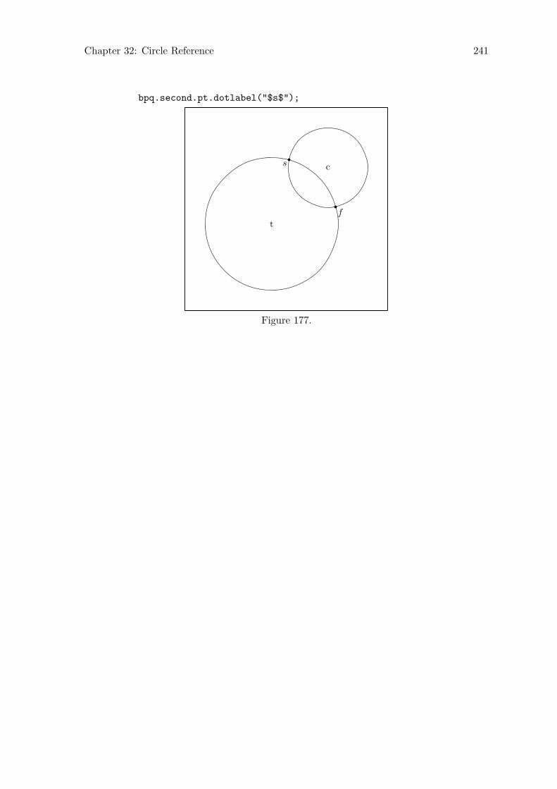
Chapter 32: Circle Reference 241
bpq.second.pt.dotlabel("$s$");
t
c
f
s
Figure 177.

Chapter 33: Pattern Reference 242
33 Pattern Reference
There is no currently no class “Pattern”. If it turns out to be useful for this purpose, I willdefine a Pattern class, and perhaps additional derived classes.
33.1 Plane Tesselations
3DLDF can be used to make perspective projections of plane tesselations and other two-dimensional patterns. These can be used for drawing tiled floors and other architecturalitems, among other things. While patterns can be generated by using the basic facilitiesof C++ and 3DLDF without any specially defined functions, it can be useful to define suchfunctions.
3DLDF currently contains only one function for drawing patterns based on a planetessellation. I plan to add more soon.
[Function]unsigned int hex pattern 1 ([real diameter_outer = 5, [realdiameter_middle = 0, [real diameter_inner = 0, [unsigned short
first_row = 5, [unsigned short double_rows = 10, [unsigned short
row_shift = 2, [Color draw_color_outer = *Colors::default_color,
[Color fill_color_outer = *Colors::background_color, [Colordraw_color_middle = *Colors::default_color, [Color fill_color_middle
= *Colors::background_color, [Color draw_color_inner =
*Colors::default_color, [Color fill_color_inner =
*Colors::background_color, [string pen_outer = "pencircle scaled
.5mm", [string pen_middle = "pencircle scaled .3mm", [string pen_inner
= "pencircle scaled .3mm", [Picture& picture = current_picture,
[unsigned int max_hexagons = 1000]]]]]]]]]]]]]]]]])Draws a pattern consisting of hexagons forming a tesselation of the x-z plane, withadditional hexagons within them.
The arguments:
real diameter outer
Default: 5. The diameter of the outer hexagon in each set of threehexagons. The outer hexagons form a tessellation of the plane.
real diameter middle
Default: 0. The diameter of the middle hexagon in a set of three hexagons.
real diameter inner
Default: 0. The diameter of the inner hexagon in a set of three hexagons.
unsigned short first row
Default: 5. The number of sets of hexagons in the first single row. Thesecond single row will have first row + 1 sets of hexagons.
unsigned short double rows
Default: 10. The number of double rows drawn.
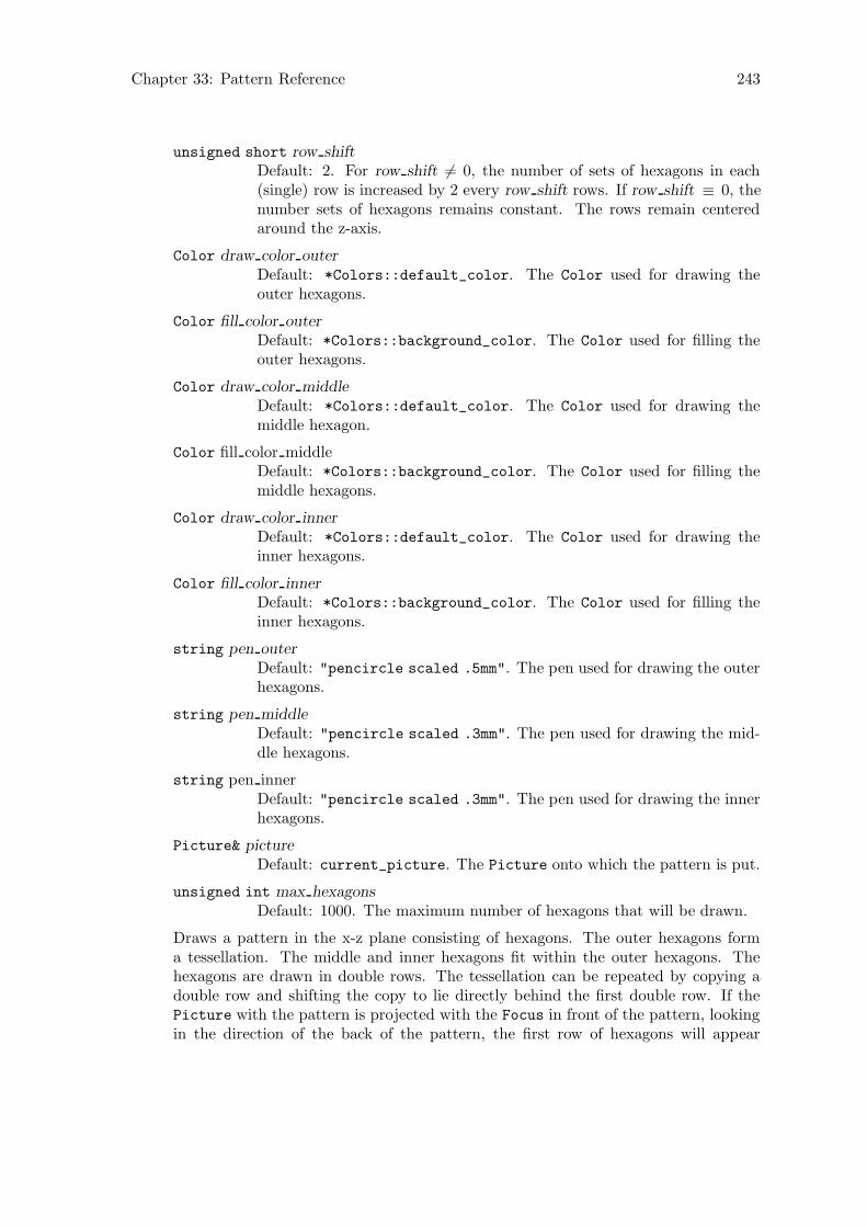
Chapter 33: Pattern Reference 243
unsigned short row shift
Default: 2. For row shift 6= 0, the number of sets of hexagons in each(single) row is increased by 2 every row shift rows. If row shift ≡ 0, thenumber sets of hexagons remains constant. The rows remain centeredaround the z-axis.
Color draw color outer
Default: *Colors::default_color. The Color used for drawing theouter hexagons.
Color fill color outer
Default: *Colors::background_color. The Color used for filling theouter hexagons.
Color draw color middle
Default: *Colors::default_color. The Color used for drawing themiddle hexagon.
Color fill color middleDefault: *Colors::background_color. The Color used for filling themiddle hexagons.
Color draw color inner
Default: *Colors::default_color. The Color used for drawing theinner hexagons.
Color fill color inner
Default: *Colors::background_color. The Color used for filling theinner hexagons.
string pen outer
Default: "pencircle scaled .5mm". The pen used for drawing the outerhexagons.
string pen middle
Default: "pencircle scaled .3mm". The pen used for drawing the mid-dle hexagons.
string pen innerDefault: "pencircle scaled .3mm". The pen used for drawing the innerhexagons.
Picture& picture
Default: current_picture. The Picture onto which the pattern is put.
unsigned int max hexagons
Default: 1000. The maximum number of hexagons that will be drawn.
Draws a pattern in the x-z plane consisting of hexagons. The outer hexagons forma tessellation. The middle and inner hexagons fit within the outer hexagons. Thehexagons are drawn in double rows. The tessellation can be repeated by copying adouble row and shifting the copy to lie directly behind the first double row. If thePicture with the pattern is projected with the Focus in front of the pattern, lookingin the direction of the back of the pattern, the first row of hexagons will appear
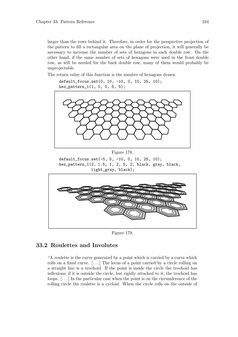
Chapter 33: Pattern Reference 244
larger than the rows behind it. Therefore, in order for the perspective projection ofthe pattern to fill a rectangular area on the plane of projection, it will generally benecessary to increase the number of sets of hexagons in each double row. On theother hand, if the same number of sets of hexagons were used in the front doublerow, as will be needed for the back double row, many of them would probably beunprojectable.
The return value of this function is the number of hexagons drawn.
default_focus.set(0, 10, -10, 0, 10, 25, 10);
hex_pattern_1(1, 0, 0, 5, 5);
Figure 178.
default_focus.set(-5, 5, -10, 0, 10, 25, 10);
hex_pattern_1(2, 1.5, 1, 2, 5, 2, black, gray, black,
light_gray, black);
Figure 179.
33.2 Roulettes and Involutes
“A roulette is the curve generated by a point which is carried by a curve whichrolls on a fixed curve. [. . . ] The locus of a point carried by a circle rolling ona straight line is a trochoid. If the point is inside the circle the trochoid hasinflexions; if it is outside the circle, but rigidly attached to it, the trochoid hasloops. [. . . ] In the particular case when the point is on the circumference of therolling circle the roulette is a cycloid. When the circle rolls on the outside of
Chapter 33: Pattern Reference 245
another circle the corresponding curves are the epitrochoids and epicycloids; ifit rolls on the inside, they are the hypotrochoids and hypocycloids.”
H. Martyn Cundy and A. P. Rollett, Mathematical Models, p. 46.
33.2.1 Epicycloids
[Function]unsigned int epicycloid pattern 1 (real diameter_inner, real
diameter_outer_start, real diameter_outer_end, real step, int
arc_divisions, unsigned int offsets, [vector<const Color*> colors =
Colors::default_color_vector])Draws a pattern consisting of epicycloids. The outer circle rolls around the circum-ference of the inner circle and a Point on the outer circle traces an epicycloid.
If offsets is greater than 1, the outer circle is rotated offset times around the centerof the inner circle by 360/offsets (starting from the outer circle’s original position).From each of these new positions, an epicycloid is drawn.
While diameter outer start is greater than or equal to diameter outer end, the diam-eter of the outer circle is reduced by step, and another set of epicycloids is traced, asdescribed above. Each time the diameter of the outer circle is reduced, a new Color
is taken from colors for the drawing commands. If there are more iterations thanColors, the last Color on colors is used for the remaining iterations.
The arguments:
real diameter inner
The diameter of the inner circle.
real diameter outer start
The diameter of the outer circle for the first iteration. It must be greaterthan or equal to diameter outer end.
real diameter outer end
The diameter of the outer circle for the last iteration. It must be lessthan or equal to diameter outer start.
real step The amount by which the diameter of the outer circle is reduced uponeach iteration.
int arc divisions
The number of divisions of the circle used for calculating Points on theepicycloid. For instance, if arc divisions is 90, then the Path for eachepicycloid will only have 4 Points, since 360/90 = 4.
unsigned int offsets
The number of epicycloids drawn upon each iteration. Each one is rotatedby 360/offsets around the center of the inner circle. offsets must begreater than or equal to 1.
vector<const Color*> colors
Default: Colors::default_color_vector. The Colors pointed to bythe pointers on this vector are used for drawing the epicycloids. OneColor is used for each iteration.
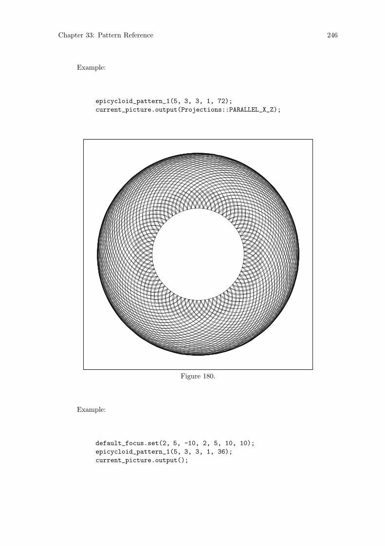
Chapter 33: Pattern Reference 246
Example:
epicycloid_pattern_1(5, 3, 3, 1, 72);
current_picture.output(Projections::PARALLEL_X_Z);
Figure 180.
Example:
default_focus.set(2, 5, -10, 2, 5, 10, 10);
epicycloid_pattern_1(5, 3, 3, 1, 36);
current_picture.output();

Chapter 33: Pattern Reference 247
Figure 181.
Chapter 34: Solid Reference 248
34 Solid Reference
Class Solid is defined in ‘solids.web’. It’s derived from Shape using public derivation. Itis intended to be used as a base class for more specialized classes representing solid figures,e.g., cuboids, polyhedra, solids of rotation, etc.
34.1 Data Members
[Protected variable]bool on free storetrue, if the Solid was dynamically allocated on the free store, otherwise false.Solids should only be allocated on the free store by create_new<Solid>(), or anal-ogous functions for derived classes. See Section 34.2 [Solid Reference; Constructorsand Setting Functions], page 249.
[Protected variable]Point centerThe center of the Solid. An object of a type derived from Solid need not have ameaningful center. However, many do, so it’s convenient to be able to access it usingthe member functions of Solid.
[Protected variable]bool do outputSet to false in Picture::output(), if the Solid cannot be projected using thearguments of that particular invocation of output(). Reset to true at the end ofPicture::output(), so that the Solid will be tested for projectability again, ifoutput() is called on the Picture again.
[Protected variables]vector<Path*> pathsvector<Circle*> circlesvector<Ellipse*> ellipsesvector <Reg_Polygon*> reg polygonsvector<Rectangle*> rectangles
Vectors of pointers to the Paths, Circles, Ellipses, Reg_Polygons, andRectangles, respectively, belonging to the Solid, if any exist.
[Protected variable]valarray<real> projective extremesThe maximum and minimum values for the x, y, and z-coordinates of the Points
belonging to the Solid. Used in Picture::output() for testing whether a Solid isprojectable using a particular set of arguments.
[Public static const variables]unsigned short CIRCLEunsigned short ELLIPSEunsigned short PATHunsigned short RECTANGLEunsigned short REG POLYGON
Used as arguments in the functions get_shape_ptr() and get_shape_center() (seeSection 34.8 [Returning Elements and Information], page 250).
Chapter 34: Solid Reference 249
34.2 Constructors and Setting Functions
[Default constructor]void Solid (void)Creates an empty Solid.
[Copy constructor]void Solid (const Solid& s )Creates a new Solid and makes it a copy of s.
[Template specializations]Solid* create new<Solid> (const Solid* s )Solid* create new<Solid> (const Solid& s )
Pseudo-constructors for dynamic allocation of Solids. They create a Solid on thefree store and allocate memory for it using new(Solid). They return a pointer to thenew Solid.
If s is a non-zero pointer or a reference, the new Solid will be a copy of s. If the newobject is not meant to be a copy of an existing one, ‘0’ must be passed to create_
new<Solid>() as its argument. See Chapter 14 [Dynamic Allocation of Shapes],page 84, for more information.
34.3 Destructor
[virtual Destructor]void ~Solid (void)This function currently has an empty definition, but its existence prevents GCC 3.3from issuing the following warning: “ ‘class Solid’ has virtual functions but non-virtualdestructor”.
34.4 Operators
[Virtual function]const Solid& operator= (const Solid& s )Assignment operator. Makes *this a copy of s, discarding the old contents of *this.
[Virtual function]Transform operator*= (const Transform& t )Multiplication by a Transform. All of the Shapes that make up the Solid are trans-formed by t.
34.5 Copying
[const virtual function]Shape* get copy (void)Dynamically allocates a new Solid on the free store, using create_new<Solid>(),and makes it a copy of *this. Then, a pointer to Shape is pointed at the copyand returned. Used for putting Solids onto Picture::shapes in the drawing andfilling functions for Solid. See Section 34.13 [Solid Reference; Drawing and Filling],page 255.
Chapter 34: Solid Reference 250
34.6 Setting Members
[Virtual function]bool set on free store ([bool b = true])Sets on_free_store to b. This function is called in the template functioncreate_new(). See Section 34.2 [Solid Reference; Constructors and SettingFunctions], page 249.
34.7 Querying
[const virtual function]bool is on free store (void)Returns the value of on_free_store; true, if the Solid was dynamically allocated onthe free store, otherwise false. Solids, and objects of classes derived from Solid,should only ever be allocated on the free store by a specialization of the templatefunction create_new(). See Section 34.2 [Solid Reference; Constructors and SettingFunctions], page 249.
34.8 Returning Elements and Information
[const virtual function]const Point& get center (void)Returns center. If the Solid doesn’t have a meaningful center, the return value willprobably be INVALID_POINT.
Getting Shape Centers
[const virtual function]const Point& get shape center (const unsigned short
shape_type, const unsigned short s )Returns the center of a Shape belonging to the Solid. Currently, the object can bea Circle, Ellipse, Rectangle, or Reg_Polygon, and it is accessed through a pointeron one of the following vectors of pointers to Shape: circles, ellipses, rectangles,or reg_polygons. The type of object is specified using the shape type argument. Thefollowing public static const data members of Solid can (and probably should) bepassed as the shape type argument: CIRCLE, ELLIPSE, RECTANGLE, and REG_POLYGON.
The argument s is used to index the vector.
This function is called within the more specialized functions in this section, namely:get_circle_center(), get_ellipse_center(), get_rectangle_center(), andget_reg_polygon_center(). I don’t expect it to be needed in user code very often.
Dodecahedron d(origin, 3);
d.filldraw();
Point C = d.get_shape_center(Solid::REG_POLYGON, 1);
C.dotlabel("C");
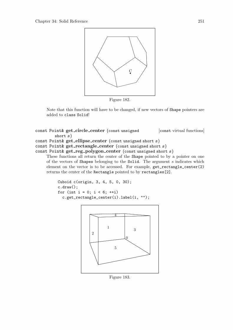
Chapter 34: Solid Reference 251
C
Figure 182.
Note that this function will have to be changed, if new vectors of Shape pointers areadded to class Solid!
[const virtual functions]const Point& get circle center (const unsigned
short s )const Point& get ellipse center (const unsigned short s )const Point& get rectangle center (const unsigned short s )const Point& get reg polygon center (const unsigned short s )
These functions all return the center of the Shape pointed to by a pointer on oneof the vectors of Shapes belonging to the Solid. The argument s indicates whichelement on the vector is to be accessed. For example, get_rectangle_center(2)returns the center of the Rectangle pointed to by rectangles[2].
Cuboid c(origin, 3, 4, 5, 0, 30);
c.draw();
for (int i = 0; i < 6; ++i)
c.get_rectangle_center(i).label(i, "");
0
1
23
4
5
Figure 183.
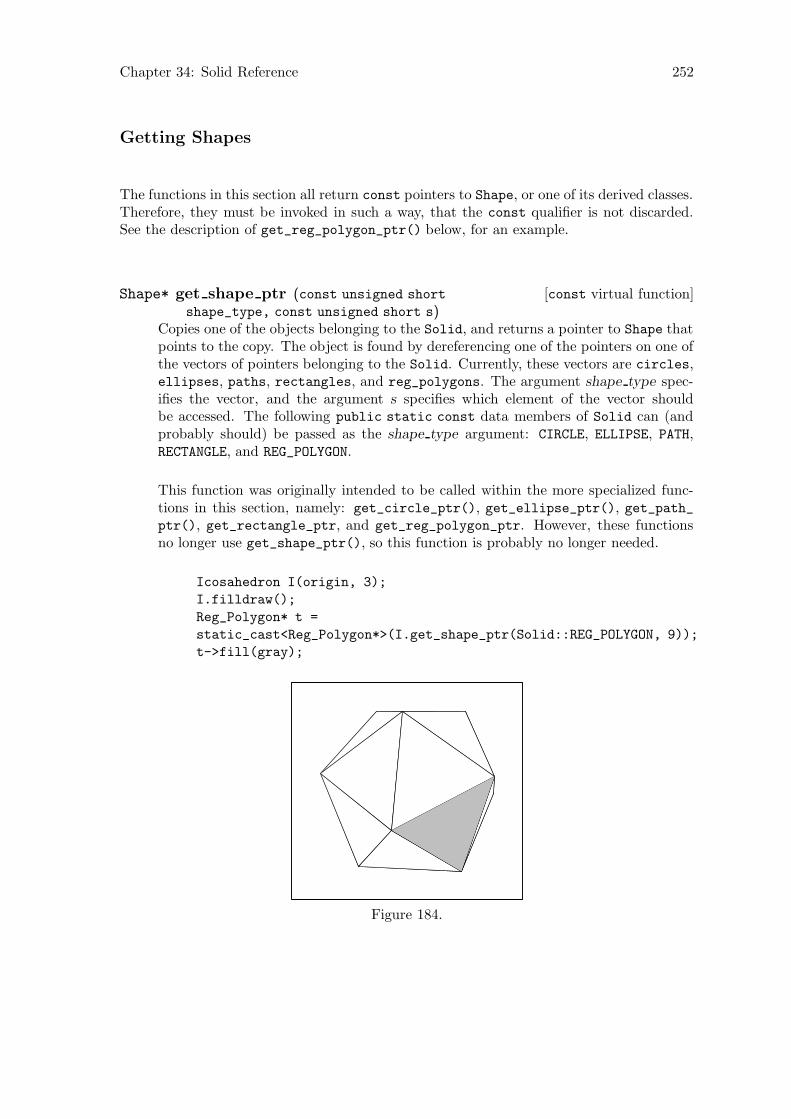
Chapter 34: Solid Reference 252
Getting Shapes
The functions in this section all return const pointers to Shape, or one of its derived classes.Therefore, they must be invoked in such a way, that the const qualifier is not discarded.See the description of get_reg_polygon_ptr() below, for an example.
[const virtual function]Shape* get shape ptr (const unsigned short
shape_type, const unsigned short s)Copies one of the objects belonging to the Solid, and returns a pointer to Shape thatpoints to the copy. The object is found by dereferencing one of the pointers on one ofthe vectors of pointers belonging to the Solid. Currently, these vectors are circles,ellipses, paths, rectangles, and reg_polygons. The argument shape type spec-ifies the vector, and the argument s specifies which element of the vector shouldbe accessed. The following public static const data members of Solid can (andprobably should) be passed as the shape type argument: CIRCLE, ELLIPSE, PATH,RECTANGLE, and REG_POLYGON.
This function was originally intended to be called within the more specialized func-tions in this section, namely: get_circle_ptr(), get_ellipse_ptr(), get_path_ptr(), get_rectangle_ptr, and get_reg_polygon_ptr. However, these functionsno longer use get_shape_ptr(), so this function is probably no longer needed.
Icosahedron I(origin, 3);
I.filldraw();
Reg_Polygon* t =
static_cast<Reg_Polygon*>(I.get_shape_ptr(Solid::REG_POLYGON, 9));
t->fill(gray);
Figure 184.
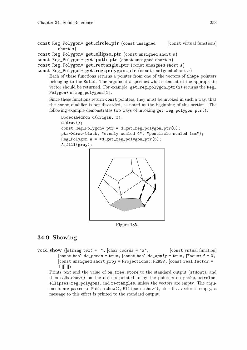
Chapter 34: Solid Reference 253
[const virtual functions]const Reg_Polygon* get circle ptr (const unsigned
short s )const Reg_Polygon* get ellipse ptr (const unsigned short s )const Reg_Polygon* get path ptr (const unsigned short s )const Reg_Polygon* get rectangle ptr (const unsigned short s )const Reg_Polygon* get reg polygon ptr (const unsigned short s )
Each of these functions returns a pointer from one of the vectors of Shape pointersbelonging to the Solid. The argument s specifies which element of the appropriatevector should be returned. For example, get_reg_polygon_ptr(2) returns the Reg_
Polygon* in reg_polygons[2].
Since these functions return const pointers, they must be invoked in such a way, thatthe const qualifier is not discarded, as noted at the beginning of this section. Thefollowing example demonstrates two ways of invoking get_reg_polygon_ptr():
Dodecahedron d(origin, 3);
d.draw();
const Reg_Polygon* ptr = d.get_reg_polygon_ptr(0);
ptr->draw(black, "evenly scaled 4", "pencircle scaled 1mm");
Reg_Polygon A = *d.get_reg_polygon_ptr(5);
A.fill(gray);
Figure 185.
34.9 Showing
[const virtual function]void show ([string text = "", [char coords = ’w’,
[const bool do_persp = true, [const bool do_apply = true, [Focus* f = 0,
[const unsigned short proj = Projections::PERSP, [const real factor =
1]]]]]]])Prints text and the value of on_free_store to the standard output (stdout), andthen calls show() on the objects pointed to by the pointers on paths, circles,ellipses, reg_polygons, and rectangles, unless the vectors are empty. The argu-ments are passed to Path::show(), Ellipse::show(), etc. If a vector is empty, amessage to this effect is printed to the standard output.

Chapter 34: Solid Reference 254
34.10 Affine Transformations
[Virtual functions]Transform scale (real x, [real y = 0, [real z = 0]])Solid. Transform shear (real xy, [real xz = 0, [real yx = 0, [real yz = 0,
[real zx = 0, [real zy = 0]]]]])Transform shift (real x, [real y = 0, [real z = 0]])Transform shift (const Point& pt )Transform rotate (const real x, [const real y = 0, [const real z = 0]])Transform rotate (const Point& p0, const Point& p1, [const real angle =
180])These functions perform the corresponding transformations on all of the Shapes be-longing to the Solid. See Section 19.10 [Transform Reference; Affine Transforma-tions], page 101.
34.11 Applying Transformations
[Virtual function]void apply transform (void)Calls apply_transform() on all of the Shapes belonging to the Solid.
34.12 Outputting
The functions in this section are are called, directly or indirectly, by Picture::output().See Section 21.8 [Picture Reference; Outputting], page 114.
[Virtual function]void output (void)Writes the MetaPost code for drawing, filling, filldrawing, undrawing, unfilling, orunfilldrawing the Solid to out_stream.
[Virtual function]void suppress output (void)Used in Picture::output(). Sets do_output to false, if the Solid cannot beprojected using a particular set of arguments to Picture::output().
[Virtual function]void unsuppress output (void)Used in Picture::output(). Resets do_output to true, so that the Solid will betested for projectability again, if the Picture it’s on is output again.
[Virtual function]vector<Shape*> extract (const Focus& f, const unsigned
short proj, real factor )Tests whether all of the Shapes belonging to the Solid are projectable, using thearguments passed to output(). If it is, this function returns a vector of pointers toShape containing a single pointer to the Solid. If not, an empty vector is returned.
[Virtual function]bool set extremes (void)Sets projective_extremes to contain the maximum and minimum values for the x,y, and z-coordinates of the Points on the Shape. Used for determining projectabilityof a Solid using a particular set of arguments.
Chapter 34: Solid Reference 255
[const inline virtual function]const valarray<real> get extremes (void)Returns projective_extremes.
[const virtual functions]real get minimum z (void)real get maximum z (void)real get mean z (void)
Returns the minimum, maximum, or mean z-value, respectively, of the Points be-longing to the Solid. Used for surface hiding. See Section 9.3 [Surface Hiding],page 67.
34.13 Drawing and Filling
[const virtual function]void draw ([const vector<const Color*> v =
Colors::default_color_vector, [const string ddashed = "", [conststring ppen = "", [Picture& picture = current_picture]]]])
Draws the Solid.
This function allocates a new Solid, makes it a copy of *this, and puts a pointer tothe copy onto picture.shapes. The data members of the Shapes belonging to thecopy are set appropriately, so that they can be drawn, when Picture::output() iscalled.
The Colors used for drawing the various Paths, Circles, Ellipses, etc., belongingto the Solid are passed in v. If the Solid contains more Shapes than v containspointers to Color, the Color pointed to by the last pointer on v is used to draw theremaining Shapes.
Currently, a Solid can only be drawn with a single dash pattern (ddashed), and pen(ppen).
[const virtual function]void fill ([const vector<const Color*> v =
Colors::default_color_vector, [Picture& picture = current_picture]])Fills the Solid.
This function allocates a new Solid makes it a copy of *this, and puts a pointer toit onto picture.shapes. The data members of the Shapes belonging to the copy areset appropriately, so that they can be filled, when Picture::output() is called.
The Colors used for filling the various Paths, Circles, Ellipses, etc., belongingto the Solid are passed in v. If the Solid contains more Shapes than v containspointers to Color, the Color pointed to by the last pointer on v is used to fill theremaining Shapes.
[const virtual function]void filldraw ([const vector<const Color*> draw_colors
= Colors::default_color_vector, [const vector<const Color*>
fill_colors = Colors::background_color_vector, [const string ddashed
= "", [const string ppen = "", [Picture& picture = current_picture]]]]])Filldraws the Solid.
This function allocates a new Solid, makes it a copy of *this, and puts a pointer toit onto picture.shapes. The data members of the Shapes belonging to the copy areset appropriately, so that they can be filldrawn, when Picture::output() is called.
Chapter 34: Solid Reference 256
The Colors used for drawing and filling the various Paths, Circles, Ellipses, etc.,belonging to the Solid are passed in draw colors and fill colors. If the Solid containsmore Shapes than draw colors contains pointers to Color, the Color pointed to bythe last pointer on draw colors is used to draw the remaining Shapes. The sameapplies to fill_colors.
Currently, a Solid can only be filldrawn with a single dash pattern (ddashed), andpen (ppen).
[const virtual function]void undraw ([const string ddashed = "", [conststring ppen = "", [Picture& picture = current_picture]]])
Undraws the Solid.
This function allocates a new Solid, makes it a copy of *this, and puts a pointer toit onto picture.shapes. The data members of the Shapes belonging to the copy areset appropriately, so that they can be undrawn, when Picture::output() is called.
A Solid can currently only be undrawn using a single dash pattern (ddashed), andpen (ppen).
[const virtual function]void unfill ([Picture& picture = current_picture])Unfills the Solid.
This function allocates a new Solid makes it a copy of *this, and puts a pointer toit onto picture.shapes. The data members of the Shapes belonging to the copy areset appropriately, so that they can be unfilled, when Picture::output() is called.
[const virtual function]void unfilldraw ([const string ddashed = "", [conststring ppen = "", [Picture& picture = current_picture]]])
[const virtual function]void undraw ([const string ddashed = "", [conststring ppen = "", [Picture& picture = current_picture]]])
Unfilldraws the Solid.
This function allocates a new Solid, makes it a copy of *this, and puts a pointerto it onto picture.shapes. The data members of the Shapes belonging to the copyare set appropriately, so that they can be unfilldrawn, when Picture::output() iscalled.
A Solid can currently only be unfilldrawn using a single dash pattern (ddashed), andpen (ppen).
34.14 Clearing
[Virtual function]void clear (void)Calls clear() on all the Shapes belonging to the Solid. Used in Picture::clear()
for deallocating and destroying Solids.
Currently, <Shape>.clear() always resolves to Path::clear(), since none of theother types of Shape that a Solid can contain, e.g., Ellipse, Circle, etc., overloadsPath::clear().
Chapter 35: Faced Solid Reference 257
35 Faced Solid Reference
Class Solid_Faced is defined in ‘solfaced.web’. It is derived from Solid using publicderivation.
Solid_Faced currently has no member functions. It is intended for use as a base class.The classes Cuboid and Polyhedron are derived from Solid_Faced. See Chapter 36 [CuboidReference], page 258, and Chapter 37 [Polyhedron Reference], page 260.
35.1 Data Members
[Protected variable]unsigned short facesThe number of faces of the Solid_Faced.
[Protected variable]unsigned short verticesThe number of vertices of the Solid_Faced.
[Protected variable]unsigned short edgesThe number of edges of the Solid_Faced.
Chapter 36: Cuboid Reference 258
36 Cuboid Reference
Class Cuboid is defined in ‘cuboid.web’. It is derived from Solid_Faced using publicderivation.
36.1 Data Members
[Protected variables]real heightreal widthreal depth
The height, width, and depth of the Cuboid, respectively.
Please note, that “height”, “width”, and “depth” are conventional terms. There areno restrictions on the orientation of a Cuboid.
36.2 Constructors and Setting Functions
[Default constructor]void Cuboid (void)Creates an empty Cuboid.
[Copy constructor]void Cuboid (const Cuboid& c )Creates a new Cuboid and makes it a copy of c.
[Constructor]void Cuboid (const Point& c, const real h, const real w, const
real d, [const real x = 0, [const real y = 0, [const real z = 0]]])Creates a Cuboid with center at the origin, with height ≡ h, width ≡ w, anddepth ≡ d. If x, y, or z is non-zero, the Cuboid is rotated by the amounts indicatedaround the corresponding main axes. Finally, the Cuboid is shifted such that centercomes to lie at c.
Point P(-3, -2, 12);
Cuboid c(P, 3, 5, 2.93, 35, 10, 60);
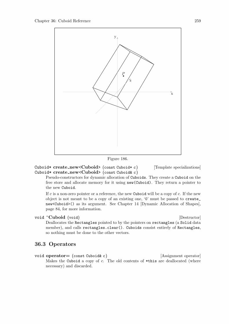
Chapter 36: Cuboid Reference 259
P
x
y
z
Figure 186.
[Template specializations]Cuboid* create new<Cuboid> (const Cuboid* c )Cuboid* create new<Cuboid> (const Cuboid& c )
Pseudo-constructors for dynamic allocation of Cuboids. They create a Cuboid on thefree store and allocate memory for it using new(Cuboid). They return a pointer tothe new Cuboid.
If c is a non-zero pointer or a reference, the new Cuboid will be a copy of c. If the newobject is not meant to be a copy of an existing one, ‘0’ must be passed to create_
new<Cuboid>() as its argument. See Chapter 14 [Dynamic Allocation of Shapes],page 84, for more information.
[Destructor]void ~Cuboid (void)Deallocates the Rectangles pointed to by the pointers on rectangles (a Solid datamember), and calls rectangles.clear(). Cuboids consist entirely of Rectangles,so nothing must be done to the other vectors.
36.3 Operators
[Assignment operator]void operator= (const Cuboid& c )Makes the Cuboid a copy of c. The old contents of *this are deallocated (wherenecessary) and discarded.
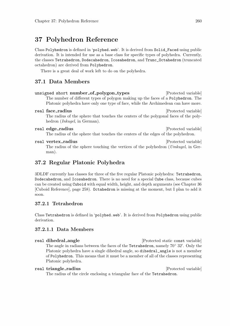
Chapter 37: Polyhedron Reference 260
37 Polyhedron Reference
Class Polyhedron is defined in ‘polyhed.web’. It is derived from Solid_Faced using publicderivation. It is intended for use as a base class for specific types of polyhedra. Currently,the classes Tetrahedron, Dodecahedron, Icosahedron, and Trunc_Octahedron (truncatedoctahedron) are derived from Polyhedron.
There is a great deal of work left to do on the polyhedra.
37.1 Data Members
[Protected variable]unsigned short number of polygon typesThe number of different types of polygon making up the faces of a Polyhedron. ThePlatonic polyhedra have only one type of face, while the Archimedean can have more.
[Protected variable]real face radiusThe radius of the sphere that touches the centers of the polygonal faces of the poly-hedron (Inkugel, in German).
[Protected variable]real edge radiusThe radius of the sphere that touches the centers of the edges of the polyhedron.
[Protected variable]real vertex radiusThe radius of the sphere touching the vertices of the polyhedron (Umkugel, in Ger-man).
37.2 Regular Platonic Polyhedra
3DLDF currently has classes for three of the five regular Platonic polyhedra: Tetrahedron,Dodecahedron, and Icosahedron. There is no need for a special Cube class, because cubescan be created using Cuboid with equal width, height, and depth arguments (see Chapter 36[Cuboid Reference], page 258). Octahedron is missing at the moment, but I plan to add itsoon.
37.2.1 Tetrahedron
Class Tetrahedron is defined in ‘polyhed.web’. It is derived from Polyhedron using publicderivation.
37.2.1.1 Data Members
[Protected static const variable]real dihedral angleThe angle in radians between the faces of the Tetrahedron, namely 70◦ 32′. Only thePlatonic polyhedra have a single dihedral angle, so dihedral_angle is not a memberof Polyhedron. This means that it must be a member of all of the classes representingPlatonic polyhedra.
[Protected variable]real triangle radiusThe radius of the circle enclosing a triangular face of the Tetrahedron.

Chapter 37: Polyhedron Reference 261
37.2.1.2 Constructors and Setting Functions
[Default constructor]void Tetrahedron (void)Creates an empty Tetrahedron.
[Constructor]void Tetrahedron (const Point& p, const real
diameter_of_triangle, [real angle_x = 0, [real angle_y = 0, [realangle_z = 0]]])
Creates a Tetrahedron with its center at the origin. The faces have enclosing circlesof diameter diameter of triangle. If any of angle x, angle y, or angle z is non-zero,the Tetrahedron is rotated by the amounts specified around the corresponding axes.Finally, if p is not the origin, the Tetrahedron is shifted such that center comes tolie at p.
The center of a Tetrahedron is the intersection of the line segments connecting thevertices with the centers of the opposite faces.
Tetrahedron t(origin, 3);
t.draw();
x
y
z
Figure 187.
Point P(1, 0, 1);
Tetrahedron t(P, 2.75, 30, 32.5, 20);
t.draw();

Chapter 37: Polyhedron Reference 262
P
x
y
z
Figure 188.
[Setting function]void set (const Point& p, const real diameter_of_triangle,
[real angle_x = 0, [real angle_y = 0, [real angle_z = 0]]])Corresponds to the constructor above.
37.2.1.3 Net
[Static function]vector<Reg_Polygon*> get net (const real
triangle_diameter )Returns the net of the Tetrahedron, i.e., the two-dimensional pattern of trianglesthat can be folded into a model of a tetrahedron.1 The net lies in the x-z plane.The triangles have enclosing circles of diameter triangle diameter. The center of themiddle triangle is at the origin.
vector<Reg_Polygon*> vrp = Tetrahedron::get_net(2);
for (vector<Reg_Polygon*>::iterator iter = vrp.begin();
iter != vrp.end();
++iter)
{
(**iter).draw();
}
1 Albrecht Durer invented this method of constructing polyhedra.
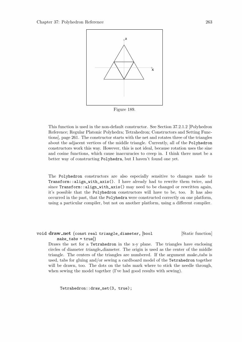
Chapter 37: Polyhedron Reference 263
x
z
x
z
Figure 189.
This function is used in the non-default constructor. See Section 37.2.1.2 [PolyhedronReference; Regular Platonic Polyhedra; Tetrahedron; Constructors and Setting Func-tions], page 261. The constructor starts with the net and rotates three of the trianglesabout the adjacent vertices of the middle triangle. Currently, all of the Polyhedron
constructors work this way. However, this is not ideal, because rotation uses the sineand cosine functions, which cause inaccuracies to creep in. I think there must be abetter way of constructing Polyhedra, but I haven’t found one yet.
The Polyhedron constructors are also especially sensitive to changes made toTransform::align_with_axis(). I have already had to rewrite them twice, andsince Transform::align_with_axis() may need to be changed or rewritten again,it’s possible that the Polyhedron constructors will have to be, too. It has alsooccurred in the past, that the Polyhedra were constructed correctly on one platform,using a particular compiler, but not on another platform, using a different compiler.
[Static function]void draw net (const real triangle_diameter, [boolmake_tabs = true])
Draws the net for a Tetrahedron in the x-y plane. The triangles have enclosingcircles of diameter triangle diameter. The origin is used as the center of the middletriangle. The centers of the triangles are numbered. If the argument make tabs isused, tabs for gluing and/or sewing a cardboard model of the Tetrahedron togetherwill be drawn, too. The dots on the tabs mark where to stick the needle through,when sewing the model together (I’ve had good results with sewing).
Tetrahedron::draw_net(3, true);
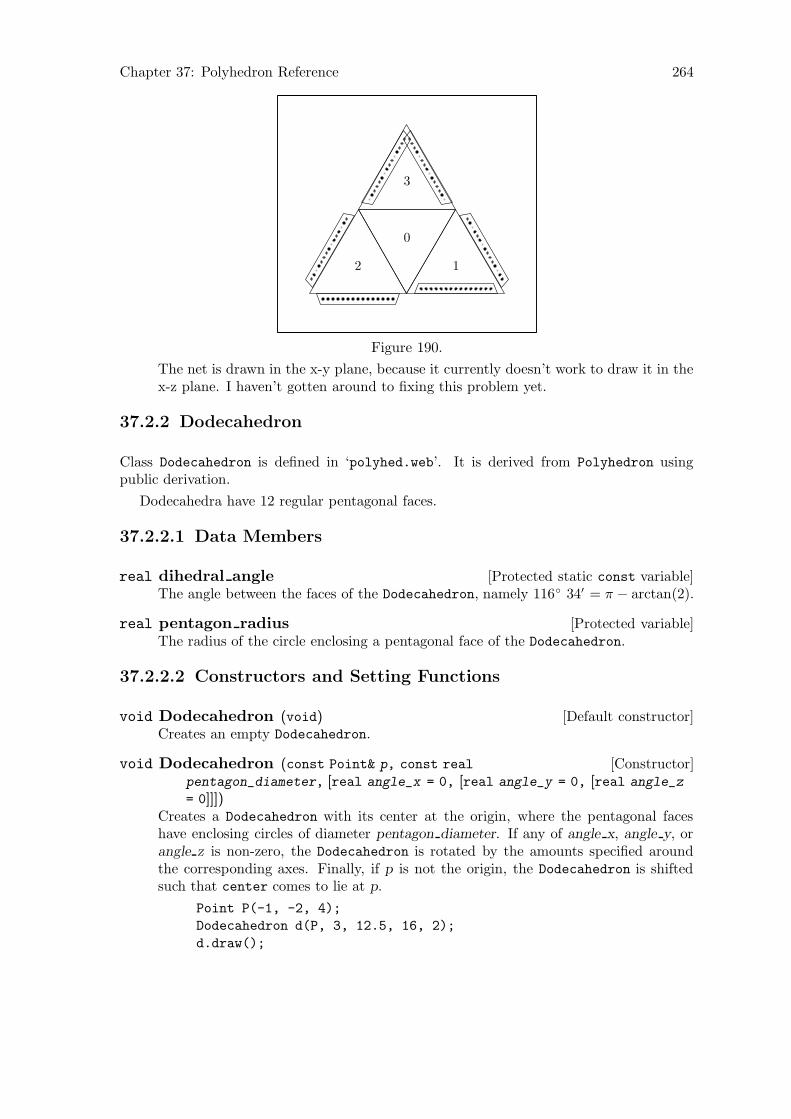
Chapter 37: Polyhedron Reference 264
0
12
3
Figure 190.
The net is drawn in the x-y plane, because it currently doesn’t work to draw it in thex-z plane. I haven’t gotten around to fixing this problem yet.
37.2.2 Dodecahedron
Class Dodecahedron is defined in ‘polyhed.web’. It is derived from Polyhedron usingpublic derivation.
Dodecahedra have 12 regular pentagonal faces.
37.2.2.1 Data Members
[Protected static const variable]real dihedral angleThe angle between the faces of the Dodecahedron, namely 116◦ 34′ = π − arctan(2).
[Protected variable]real pentagon radiusThe radius of the circle enclosing a pentagonal face of the Dodecahedron.
37.2.2.2 Constructors and Setting Functions
[Default constructor]void Dodecahedron (void)Creates an empty Dodecahedron.
[Constructor]void Dodecahedron (const Point& p, const real
pentagon_diameter, [real angle_x = 0, [real angle_y = 0, [real angle_z
= 0]]])Creates a Dodecahedron with its center at the origin, where the pentagonal faceshave enclosing circles of diameter pentagon diameter. If any of angle x, angle y, orangle z is non-zero, the Dodecahedron is rotated by the amounts specified aroundthe corresponding axes. Finally, if p is not the origin, the Dodecahedron is shiftedsuch that center comes to lie at p.
Point P(-1, -2, 4);
Dodecahedron d(P, 3, 12.5, 16, 2);
d.draw();
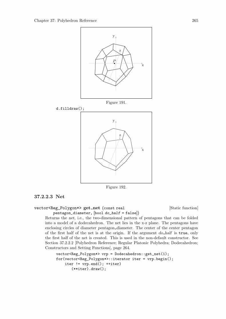
Chapter 37: Polyhedron Reference 265
Px
y
z
Figure 191.
d.filldraw();
x
y
z
Figure 192.
37.2.2.3 Net
[Static function]vector<Reg_Polygon*> get net (const real
pentagon_diameter, [bool do_half = false])Returns the net, i.e., the two-dimensional pattern of pentagons that can be foldedinto a model of a dodecahedron. The net lies in the x-z plane. The pentagons haveenclosing circles of diameter pentagon diameter. The center of the center pentagonof the first half of the net is at the origin. If the argument do half is true, onlythe first half of the net is created. This is used in the non-default constructor. SeeSection 37.2.2.2 [Polyhedron Reference; Regular Platonic Polyhedra; Dodecahedron;Constructors and Setting Functions], page 264.
vector<Reg_Polygon*> vrp = Dodecahedron::get_net(1);
for(vector<Reg_Polygon*>::iterator iter = vrp.begin();
iter != vrp.end(); ++iter)
(**iter).draw();

Chapter 37: Polyhedron Reference 266
Figure 193.
[Static function]void draw net (const real pentagon_diameter, [bool portrait
= true, [bool make_tabs = true]])Draws the net for a Dodecahedron in the x-z plane. The pentagons have enclosingcircles of diameter pentagon diameter. The origin is used as the center of the middlepentagon of the first half of the net. The centers of the pentagons are numbered.
If the argument portrait is true (the default), the net is arranged for printing inportrait format. If it’s false, it’s arranged for printing in landscape format.
The argument make tabs currently has no effect. When I get around to programmingthis, it will be used for specifying whether tabs for gluing and/or sewing a cardboardmodel should be drawn, too.
Dodecahedron::draw_net(1, false);
0
12
3
4
5 6
7 8
9
10
11
Figure 194.
37.2.3 Icosahedron
Class Icosahedron is defined in ‘polyhed.web’. It is derived from Polyhedron using publicderivation.
Icosahedra have 20 regular triangular faces.
37.2.3.1 Data Members
[Protected static const variable]real dihedral angleThe angle between the faces of the Icosahedron, namely 138◦ 11′ = π− arcsin(2/3).
[Protected variable]real triangle radiusThe radius of the circle enclosing a triangular face of the Icosahedron.
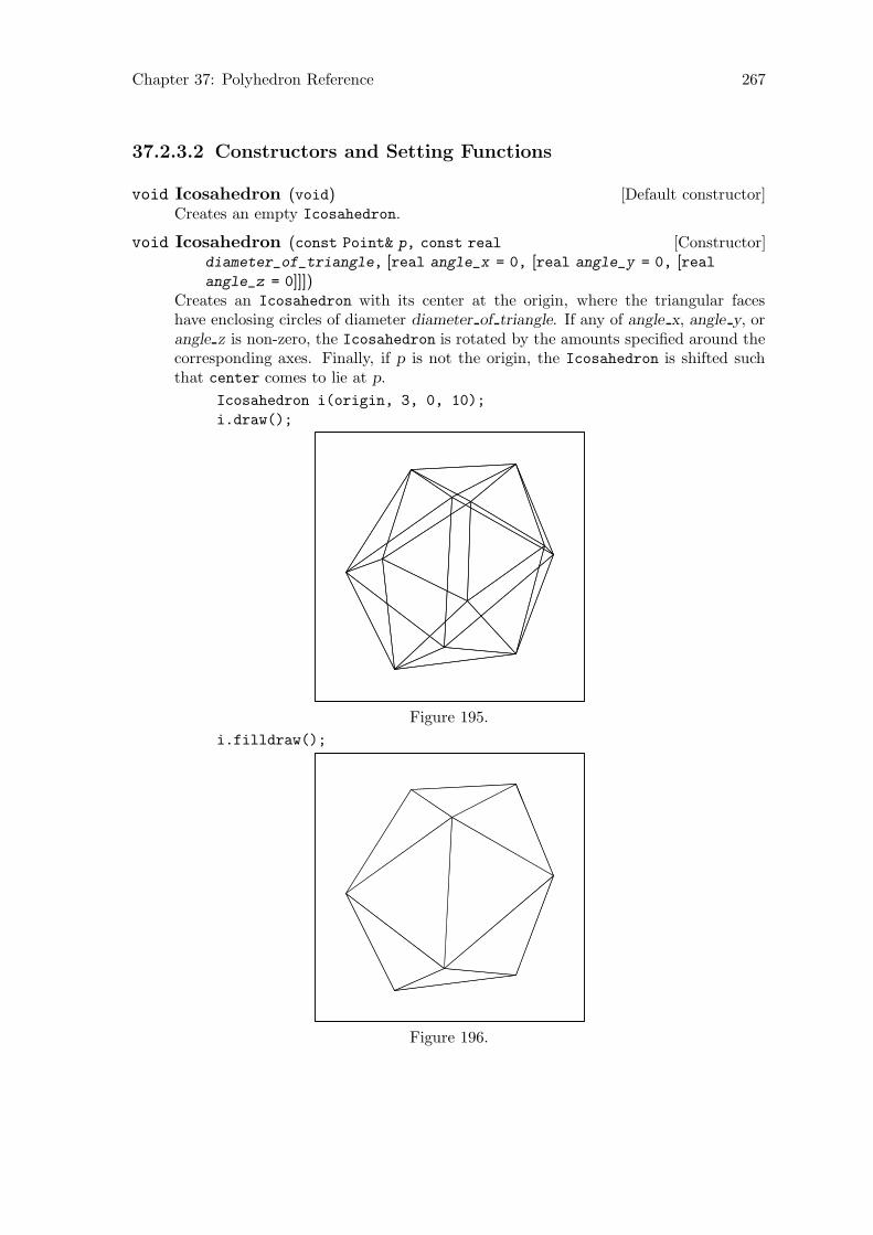
Chapter 37: Polyhedron Reference 267
37.2.3.2 Constructors and Setting Functions
[Default constructor]void Icosahedron (void)Creates an empty Icosahedron.
[Constructor]void Icosahedron (const Point& p, const real
diameter_of_triangle, [real angle_x = 0, [real angle_y = 0, [realangle_z = 0]]])
Creates an Icosahedron with its center at the origin, where the triangular faceshave enclosing circles of diameter diameter of triangle. If any of angle x, angle y, orangle z is non-zero, the Icosahedron is rotated by the amounts specified around thecorresponding axes. Finally, if p is not the origin, the Icosahedron is shifted suchthat center comes to lie at p.
Icosahedron i(origin, 3, 0, 10);
i.draw();
Figure 195.
i.filldraw();
Figure 196.
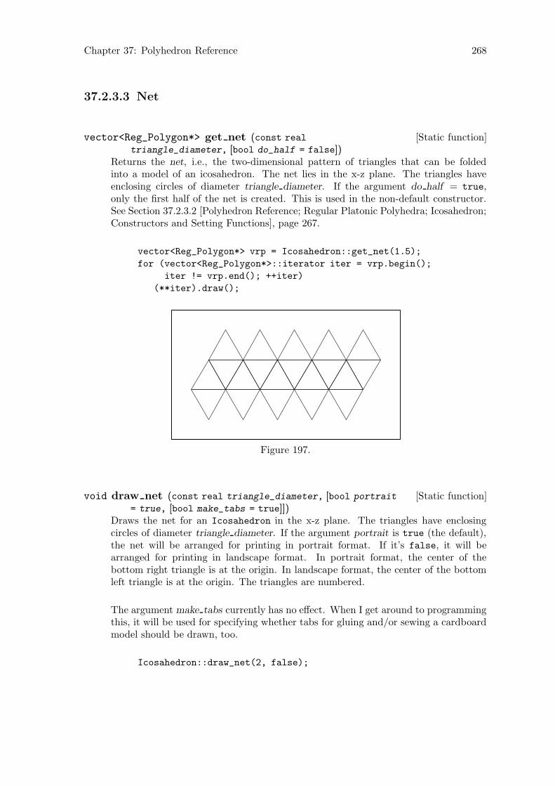
Chapter 37: Polyhedron Reference 268
37.2.3.3 Net
[Static function]vector<Reg_Polygon*> get net (const real
triangle_diameter, [bool do_half = false])Returns the net, i.e., the two-dimensional pattern of triangles that can be foldedinto a model of an icosahedron. The net lies in the x-z plane. The triangles haveenclosing circles of diameter triangle diameter. If the argument do half = true,only the first half of the net is created. This is used in the non-default constructor.See Section 37.2.3.2 [Polyhedron Reference; Regular Platonic Polyhedra; Icosahedron;Constructors and Setting Functions], page 267.
vector<Reg_Polygon*> vrp = Icosahedron::get_net(1.5);
for (vector<Reg_Polygon*>::iterator iter = vrp.begin();
iter != vrp.end(); ++iter)
(**iter).draw();
Figure 197.
[Static function]void draw net (const real triangle_diameter, [bool portrait
= true, [bool make_tabs = true]])Draws the net for an Icosahedron in the x-z plane. The triangles have enclosingcircles of diameter triangle diameter. If the argument portrait is true (the default),the net will be arranged for printing in portrait format. If it’s false, it will bearranged for printing in landscape format. In portrait format, the center of thebottom right triangle is at the origin. In landscape format, the center of the bottomleft triangle is at the origin. The triangles are numbered.
The argument make tabs currently has no effect. When I get around to programmingthis, it will be used for specifying whether tabs for gluing and/or sewing a cardboardmodel should be drawn, too.
Icosahedron::draw_net(2, false);
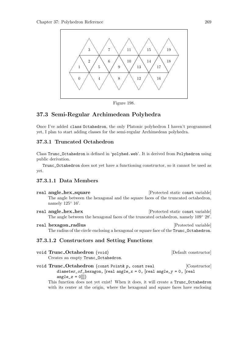
Chapter 37: Polyhedron Reference 269
0
1
2
3
4
5
6
7
8
9
10
11
12
13
14
15
16
17
18
19
Figure 198.
37.3 Semi-Regular Archimedean Polyhedra
Once I’ve added class Octahedron, the only Platonic polyhedron I haven’t programmedyet, I plan to start adding classes for the semi-regular Archimedean polyhedra.
37.3.1 Truncated Octahedron
Class Trunc_Octahedron is defined in ‘polyhed.web’. It is derived from Polyhedron usingpublic derivation.
Trunc_Octahedron does not yet have a functioning constructor, so it cannot be used asyet.
37.3.1.1 Data Members
[Protected static const variable]real angle hex squareThe angle between the hexagonal and the square faces of the truncated octahedron,namely 125◦ 16′.
[Protected static const variable]real angle hex hexThe angle between the hexagonal faces of the truncated octahedron, namely 109◦ 28′.
[Protected variable]real hexagon radiusThe radius of the circle enclosing a hexagonal or square face of the Trunc_Octahedron.
37.3.1.2 Constructors and Setting Functions
[Default constructor]void Trunc Octahedron (void)Creates an empty Trunc_Octahedron.
[Constructor]void Trunc Octahedron (const Point& p, const real
diameter_of_hexagon, [real angle_x = 0, [real angle_y = 0, [realangle_z = 0]]])
This function does not yet exist! When it does, it will create a Trunc_Octahedron
with its center at the origin, where the hexagonal and square faces have enclosing
Chapter 37: Polyhedron Reference 270
circles of diameter diameter of hexagon. If any of angle x, angle y, or angle z isnon-zero, the Trunc_Octahedron will be rotated by the amounts specified around thecorresponding axes. Finally, if p is not the origin, the Trunc_Octahedron will beshifted such that center comes to lie at p.
37.3.1.3 Net
[Static function]vector<Reg_Polygon*> get net (const real
hexagon_diameter, [bool do_half = false])This function does not yet exist! When it does, it will return the net, i.e., the two-dimensional pattern of hexagons and squares that can be folded into a model of atruncated octahedron. The net will lie in the x-z plane. The hexagons and squareswill have enclosing circles of diameter hexagon diameter. If the argument do half istrue, only the first half of the net will be created. This will be used in the non-defaultconstructor. See Section 37.3.1.2 [Polyhedron Reference; Regular Platonic Polyhedra;Truncated Octahedron Constructors and Setting Functions], page 269.

Chapter 38: Utility Functions 271
38 Utility Functions
[Function]double trunc (double d)Defined in ‘pspglb.web’. For some reason, when I compile 3DLDF using GNU CC ona PC Pentium II XEON under Linux 2.4.4 i686, the standard library function trunc()
is not available. Therefore, I’ve had to write one. This is a kludge! Someday, I’ll haveto try to find a better solution to this problem.
[Function]pair<real, real> solve quadratic (real a, real b, real c )Defined in ‘pspglb.web’. This function tries to find the solutions S0 and S1 to the
quadratic equation ax2 + bx + c according to the formulae S0 ≡ (−b +√
b2 − 4ac)/2a
and S1 ≡ (−b −√
b2 − 4ac)/2a. Let r stand for the return value. If S0 cannot be
found, r.first will be INVALID_REAL, otherwise S0. If S1 cannot be found, r.secondwill be INVALID_REAL, otherwise S1.
(x + 4)(x + 2) = x2 + 6x + 8 = 0
real_pair r = solve_quadratic(1, 6, 8);⇒ r.first ≡ -2⇒ r.second ≡ -4
real_pair r = solve_quadratic(1, -2, 4);⇒ r.first ≡ INVALID_REAL⇒ r.second ≡ INVALID_REAL
38.1 Perspective Functions
[Function]void persp 0 (const real front_corner_x, const real
front_corner_z, const real side_lft, const real side_rt, const real
angle_rt, const real f_2_cv, const real gl_2_cv, [const real
horizon_lft = 6, [real horizon_rt = 0, [real gl_lft = 0, [real gl_rt =
0]]]])Defined in ‘utility.web’. This function is used for the figure in Section 9.1.2 [ThePerspective Projection], page 60, illustrating a perspective projection as it could bedone by hand. It draws a rectangle in the ground plane and the construction linesused for putting it into perspective. It also labels the vanishing and measuring points.
The arguments:
const real front corner x
The x-coordinate of the front corner of the rectangle.
const real front corner z
The z-coordinate of the front corner of the rectangle.
const real side lft
The length of the left side of the rectangle.
const real side rt
The length of the right side of the rectangle.

Chapter 38: Utility Functions 272
const real angle rt
The angle at which the right side of the rectangle recedes to the horizon.
const real f 2 cv
The distance from the focus to the center of vision.
const real gl 2 cv
The distance of the ground line to the center of vision.
const real horizon lft
Default: 6. The length of the horizon line leftwards of the center of vision.
real horizon rt
Default: 0. The length of the horizon line rightwards of the center ofvision.
real gl lft
Default: 0. The length of the ground line leftwards of the line from thefocus to the center of vision.
real gl rt Default: 0. The length of the ground line rightwards of the line from thefocus to the center of vision.
Example:
persp_0(3, 2, 10, 5, 47.5, 7, 5, 8.5, 9.5, 8.5, 9.5);
focus
CVhorizon
ground line
VP 47.5◦rMP 47.5◦rVP 42.5◦l MP 42.5◦l
MP-CV
xr0= 3zr0
= 2
r0
0 5
r1
010
r3
r2
R
CV: center of visionVP: vanishing pointMP: measuring point
l: leftr: right
Figure 199.
Chapter 39: Adding a File 273
39 Adding a File
Version 1.1.1 was the first version of 3DLDF since it became a GNU package (the cur-rent version is 1.1.5.1). In previous versions, recompilation was controlled by an auxilliaryprogram, which I wrote in C++ using CWEB. However, in the course of making 3DLDFconformant to the GNU Coding Standards1, this has been changed. Recompilation is nowcontrolled by make, as is customary. The chapter “Compiling” in previous editions of thismanual, is therefore no longer needed.
Nonetheless, using CWEB still has consequences for the way recompilation must behandled, and it was fairly tricky getting make to work for 3DLDF. Users who only putcode in ‘main.web’ and/or change code in existing files won’t have to worry about this; forothers, this chapter explains how to add files to 3DLDF.
Let’s say you want to add a file ‘widgets.web’ that defines a class Widget, and that thelatter needs access to class Rectangle, and is in turn required by class Ellipse. Codemust be added to ‘3DLDF-1.1.5.1/CWEB/Makefile’ for ctangling ‘widgets.web’, compiling‘widgets.cxx’, and linking ‘widgets.o’ with the other object files to make the executable‘3dldf’.
The best way to do this is to change ‘3DLDF-1.1.5.1/CWEB/Makefile.am’ and use Au-tomake to generate a new ‘Makefile.in’. Then, configure can be used to generate a new‘Makefile’. It would be possible to modify ‘Makefile’ by hand, but I don’t recommendit. The following assumes that the user has access to Automake. If he or she is using aGNU/Linux system, this is probably true.2
‘widgets.web’ must be added between ‘rectangs.web’ and ‘ellipses.web’ in the fol-lowing variable declaration in ‘3DLDF-1.1.5.1/CWEB/Makefile.am’:
3dldf_SOME_CWEBS = pspglb.web io.web colors.web transfor.web \
shapes.web pictures.web points.web \
lines.web planes.web paths.web curves.web \
polygons.web rectangs.web ellipses.web \
circles.web patterns.web solids.web
solfaced.web cuboid.web polyhed.web \
utility.web parser.web examples.web
Now, add ‘widgets.o’ between ‘ellipses.o’ and ‘rectangs.o’ in the following variabledeclaration:
3dldf_OBS_REVERSED = main.o examples.o parser.o utility.o \
polyhed.o cuboid.o solfaced.o solids.o \
patterns.o circles.o ellipses.o rectangs.o \
polygons.o curves.o paths.o \
planes.o lines.o points.o pictures.o shapes.o
transfor.o colors.o io.o pspglb.o
3dldf_OBS_REVERSED is needed, because 3DLDF fails with a “Segmentation fault”, ifthe executable is linked using $(3dldf_OBJECTS). This may cause problems, if ‘3dldf’ isn’tbuilt using the GNU C++ compiler (GCC).
1 The GNU Coding Standards are available at http://www.gnu.org/prep/standards_toc.html.2 Automake is available for downloading from http://ftp.gnu.org/gnu/automake/. The Automake web-
site is at http://www.gnu.org/software/automake/.
Chapter 39: Adding a File 274
Now add a target for ‘widgets.o’ between the targets for ‘rectangs.o’ and‘ellipses.o’, and add ‘widgets.tim’ after ‘rectangs.tim’ in the list of prerequisites for‘ellipses.o’:
rectangs.o: loader.tim pspglb.tim io.tim colors.tim transfor.tim \
shapes.tim pictures.tim points.tim lines.tim planes.tim \
paths.tim curves.tim polygons.tim rectangs.cxx
ellipses.o: loader.tim pspglb.tim io.tim colors.tim transfor.tim \
shapes.tim pictures.tim points.tim lines.tim planes.tim \
paths.tim curves.tim polygons.tim rectangs.tim ellipses.cxx
This is the result:
rectangs.o: loader.tim pspglb.tim io.tim colors.tim transfor.tim \
shapes.tim pictures.tim points.tim lines.tim planes.tim \
paths.tim curves.tim polygons.tim rectangs.cxx
widgets.o: loader.tim pspglb.tim io.tim colors.tim transfor.tim \
shapes.tim pictures.tim points.tim lines.tim planes.tim \
paths.tim curves.tim polygons.tim rectangs.tim \
widgets.cxx
ellipses.o: loader.tim pspglb.tim io.tim colors.tim transfor.tim \
shapes.tim pictures.tim points.tim lines.tim planes.tim \
paths.tim curves.tim polygons.tim rectangs.tim widgets.tim \
ellipses.cxx
In addition, ‘widgets.tim’ must be added to the list of prerequisites in all of the followingtargets up to and including ‘examples.o’.
Chapter 40: Future Plans 275
40 Future Plans
3DLDF is a work-in-progress. In fact, it can never be finished, because the supply ofinteresting geometric constructions is inexhaustible. However, presently 3DLDF still has anumber of major gaps.
If you’re interesting in contributing to 3DLDF, with respect to one of the topics belowand in the following sections, or if you have ideas of your own, see Section 1.7 [Contributingto 3DLDF], page 9.
• Input routine. The lack of one is the most significant defect in 3DLDF, as mentionedin Section 1.5.2 [No Input Routine], page 8.
• Port to other platforms. See Section 1.6 [Ports], page 8.
40.1 Geometry
3DLDF currently provides a set of basic plane and solid geometrical figures. However,some important ones are still missing. There are many useful geometrical data types andfunctions whose implementation would require no more than elementary geometry.
• Add constructors with a normal vector argument rather than angles of rotation aboutthe main axes.
• I have started defining class Triangle, which can be used for calculating trianglesolutions.
• Add a class Conic_Section and derive Ellipse from it. This will be the first caseof multiple inheritance1 in 3DLDF, since Ellipse is already derived from Path. SeeChapter 31 [Ellipse Reference], page 222. Add the classes Parabola and Hyperbola.
• Add more functions for finding the intersections of objects of various types, startingwith the plane figures. In particular, I believe I’ve found an algebraic solution for theintersection of an Ellipse and a Circle in a plane, but I haven’t had a chance to tryimplementing it yet.
If this works, I think it will make it possible to find the intersection of two coplanarellipses algebraically, because it will be possible to transform them both such that oneof them becomes circular.
• Class Octahedron will complete the set of regular Platonic polyhedra.
• Add classes for the Kepler-Poinsot polyhedra, the semi-regular Archimedean polyhedra,the dual solids, the stellated Archimedean polyhedra, and the regular compounds.2
• Add class Ellipsoid and a derived class Sphere.
• Improve the specification of Solid and Solid_Faced. In particular, it would help tostore the vertices of Polyhedra as individual Points, rather than using Reg_Polygons.I’d also like to find a better way of generating Solids, without using rotations, ifpossible.
1 Stroustrup, The C++ Programming Language, §15.2 “Multiple Inheritance”, pp. 390–92.2 Cundy and Rollet, Mathematical Models, Chapter 3, “Polyhedra”, pp. 76–160.
Chapter 40: Future Plans 276
40.2 Curves and Surfaces
3D modelling software usually supports the creation and manipulation of various kindsof spline curves: Bezier curves, B-splines, and non-uniform rational B-splines or NURBS.These curves can be used for generating surfaces.3
paths in Metafont and MetaPost are Bezier curves. It would be possible to implementthree-dimensional Bezier curves in 3DLDF, but unfortunately they are not projectively
invariant:
Let c0 represent a Bezier curve in three dimensions, P the control points of c0, and t aprojection transformation. Further, let Q represent the points generated from applying t toP , and c1 the curve generated from Q. Finally, let R represent the points generated fromapplying t to all of the points on c0, and c2 the curve through R: c1 6≡ c2.
NURBS, on the other hand, are projectively invariant,4 so I will probably concentrate onimplementing them. On the other hand, it would be nice to be able to implement Metafont’sway of specifying paths using ‘curl’, ‘tension’, and ‘dir’ in 3DLDF. This may prove tobe difficult or impossible. I do not yet know whether Metafont’s path creation algorithmcan be generalized to three dimensions.5
Curves and surfaces are advanced topics, so it may be a while before I implement themin 3DLDF.
40.3 Shadows, Reflections, and Rendering
Shadows and reflections are closely related to transformations and projections. A shadowis the projection of the outline of an object onto a surface or surfaces, and reflection in aplane is an affine transformation.
3D rendering software generally implements shadows, or more generally, shading, reflec-tions, and certain other effects using methods involving the calculation of individual pixelvalues. Surface hiding is also often implemented at the pixel level. 3DLDF does no scanconverting ((see Section 1.5.1 [Accuracy], page 7), and hence no calculation of pixel valuesat all, so these methods cannot be used in 3DLDF at present.
However, it is possible to define functions for generating shadows and reflections within3DLDF by other means.
I have defined the function Point::reflect() for reflecting a Point in a Plane, andhave begun definining versions for other classes.
However, in order for reflections to work, I must define functions for breaking up objectsinto smaller units. This is also necessary for surface hiding to work properly.
For MetaPost output, I will have to implement shadows, reflections, and surface hidingin this way. However, 3DLDF could be made to produce output in other formats. Thereare two possibilities: implementing rendering functionality within 3DLDF, or interfacing to
3 Huw Jones, Computer Graphics through Key Mathematics, and David Salomon, Computer Graphics and
Geometric Modeling, are my main sources of information about spline curves.4 Jones, Huw. Computer Graphics through Key Mathematics, p. 282.5 Knuth, Donald Ervin. The METAFONTbook, p. 130, and Hobby, John D. Smooth, Easy to Compute
Interpolating Splines. Discrete and Computational Geometery 1(2).

Chapter 40: Future Plans 277
existing rendering software. If I decide to do the latter, there are again two possibilities:having 3DLDF write output in a format that a renderer can input, or linking to a librarysupplied by a rendering package.
I haven’t yet decided which course to pursue. However, in the long run, I’d like it to bepossible to use 3DLDF for fancier graphics than is currently possible using MetaPost andPostScript alone.
40.4 Multi-Threading
When 3DLDF is run, there is only one thread of execution. However, it could benefitfrom the use of multiple threads. In particular, it may be faster and more efficient to havePicture::output() run in its own thread. In this case, it will no longer be possible toshare current_picture among figures.
It may also be worthwhile to execute the code for “figures”, i.e., the code between‘beginfig()’ and ‘endfig()’, inclusive, in their own threads. This will require some changesin the way data are handled. For example, if non-constant objects are shared amongfigures, there may be no advantage to multi-threading because of the need to coordinatethe access of the threads to the objects. If threads are used, then non-constant objectsshould be declared locally within the figure. They may be locally declared copies of globalobjects. Alternatively, beginfig() could be changed so that objects could be passed to itas arguments, perhaps as a vector<void*> and/or a vector<Shape*>.
Chapter 41: Changes 278
41 Changes
Updated 16 January 2004.
41.1 3DLDF 1.1.5.1
• Added missing Texinfo files to the 3dldf_TEXINFOS variable in ‘3DLDF-1.1.5.1/DOC/TEXINFO/Makefile.am’,and reordered the filenames.
• Changed the names of the PNG (Portable Network Graphics) files included in theHTML version of this manual. Changed the names in the commands for includingthese files in the Texinfo files. I wasn’t able to write some of the files with the oldnames to a CD-R (Compact Disk, Recordable).
41.2 3DLDF 1.1.5
In release 1.1.5, I’ve tied up some loose ends. I wanted to do this before starting on theinput routine.
• Added const real step argument to the version of Ellipse::intersection_points()that takes an Ellipse argument. See Section 31.9 [Ellipse Reference; Intersections],page 230.
• It is now possible to “typedef” real to either float or double. This means that realcan now be made a synonym for either float or double by using a typedef declaration.real is typedeffed to float by default.
• Added const bool ldf_real_float and extern const bool ldf_real_double foruse in non-conditionally compiled code. They are set according to the values ofLDF_REAL_FLOAT and LDF_REAL_DOUBLE.
• Transform::epsilon() and Point::epsilon() now return different values, dependingon the values of the preprocessor macros LDF_REAL_FLOAT and LDF_REAL_DOUBLE. Ihave not yet tested whether good values are returned when real is double.
• MAX_REAL and MAX_REAL_SQRT are no longer constants. Their values are set at thebeginning of main(). However, users should not change their values. MAX_REAL is thesecond-largest float or double on a given machine. This now works for all commonarchitectures.
• Added namespace System containing the following functions: get_endianness(), is_big_endian(), is_little_endian(), get_register_width(), is_32_bit(), is_64_bit(), and the template function get_second_largest().
namespace System and its functions are documented in ‘system.texi’, which is newin edition 1.1.5.1.
• Replaced the various create_new_<type>() functions with the template functioncreate_new(). The latter is documented in ‘creatnew.texi’, which is new in edition1.1.5.1.
• Added the file ‘3DLDF-1.1.5.1/CWEB/cnepspng.el’ to the distribution. It contains thedefinitions of the Emacs-Lisp functions convert-eps and convert-eps-loop. See Sec-tion 11.2.1.1 [Running 3DLDF; Converting EPS Files; Emacs-Lisp Functions], page 79.

Chapter 41: Changes 279
• Added the files ‘3DLDF-1.1.5.1/CWEB/exampman.web’ and ‘3DLDF-1.1.5.1/CWEB/examples.mp’to the distribution. They contain the C++ and MetaPost code, respectively, forgenerating the illustrations in this manual.
41.3 3DLDF 1.1.4.2
• The illustrations in the HTML output are now scaled to magstep3.
41.4 3DLDF 1.1.4.1
• The HTML output now includes illustrations.
41.5 3DLDF 1.1.4
• MAX_REAL is now the second largest float value. However, the calculation is systemdependent, and will only work on 32-bit little-endian architectures. I will start workingon porting this soon.
• Fixed bug in ‘tsthdweb’, that caused files to be compiled more often than necessary.It will be necessary to keep an eye on this.
• Added Rectangle::is_rectangular().
• Made mediate() a member function of Point.
• It is now possible to generate this manual in the Info and HTML formats.
41.6 3DLDF 1.1.1
3DLDF 1.1.1 was the first version of 3DLDF since it became a GNU package (the currentversion is 1.1.5.1). It is now conformant to the GNU Coding Standards, except that afunctioning ‘3DLDF.info’ cannot be generated from ‘3DLDF.texi’. The distribution nowincludes a configure script, ‘Makefile.in’ files, and other files generated by Autoconfand Automake. Recompilation is now handled by make rather than the auxilliary program3DLDFcpl. The files ‘3DLDFcpl.web’ and ‘3DLDFprc.web’ have been removed from thedistribution.
The extension of the C++ files generated by ctangle is changed from ‘c’ to ‘cxx’ beforethey are compiled. After ctangle is run on a CWEB file, ‘<filename>.c’ is comparedto the old ‘<filename>.cxx’ using diff. Whitespace, comments, and #line preprocessorcommands are ignored. The ‘<filename>.c’ is only renamed to ‘<filename>.cxx’ andcompiled if they differ. This way, changes to the TEX text only in a CWEB file no longercause recompilation and relinking.
The main Texinfo file is now called ‘3DLDF.texi’. It was formerly called‘3DLDFman.texi’. This is because Automake expects this name. For this reason, theCWEB file passed as an argument to cweave has been renamed ‘3DLDFprg.web’. It wasformerly called ‘3DLDF.web’.

Bibliography 280
Bibliography
Cundy, H. Martyn and A.P. Rollet. Mathematical Models. Oxford 1961. Oxford UniversityPress.
Unfortunately out of print.
Finston, Laurence D. 3DLDF: The Program. Gottingen 2003.
Fischer, Gerd. Ebene algebraische Kurven. Vieweg Studium. Aufbaukurs Mathematik.Friedr. Vieweg & Sohn Verlagsgesellschaft mbH. Braunschweig/Wiesbaden 1994.
Gill, Robert W. Creative Perspective. London 1975. Thames and Hudson Ltd.ISBN 0-500-27056-2.
Harbison, Samuel P., and Guy L. Steele Jr. C, A Reference Manual. Pren-tice Hall. Englewood Cliffs, New Jersey 1995. ISBN 0-13-326232-4 –Case˝.ISBN~0-13-326224-3 –Paperback˝.
Hobby, John D. Smooth, Easy to Compute Interpolating Splines. Discrete and Computa-tional Geometery 1(2). Springer-Verlag. New York 1986.
Hobby, John D. A User’s Manual for MetaPost. AT & T Bell Laboratories. Murray Hill,NJ. No date.
Jones, Huw. Computer Graphics through Key Mathematics. Springer-Verlag London Lim-ited 2001. ISBN 1-85233-422-3.
Knuth, Donald Ervin. Metafont: The Program. Computers and Typesetting; D. AddisonWesley Publishing Company, Inc. Reading, Massachusetts 1986. ISBN 0-201-13438-1.
Knuth, Donald Ervin. The METAFONTbook. Computers and Typesetting; C. AddisonWesley Publishing Company, Inc. Reading, Massachusetts 1986.
Knuth, Donald Ervin. TEX: The Program. Computers and Typesetting; B. Addison WesleyPublishing Company, Inc. Reading, Massachusetts 1986. ISBN 0-201-13437-3.
Knuth, Donald E. The TEXbook. Computers and Typesetting; A. Addison Wesley Publish-ing Company, Inc. Reading, Massachusetts 1986.
Knuth, Donald E. and Silvio Levy. The CWEB System of Structured Documentation.Version 3.64—February 2002.
Rokicki, Tomas. Dvips: A DVI-to-PostScript Translator for version 5.66a. February 1997.http://dante.ctan.org/CTAN/dviware/dvips/
Salomon, David. Computer Graphics and Geometric Modeling. Berlin 1999. Springer-Verlag. ISBN: 0-387-98682-0.
Stallman, Richard M. and Roland McGrath. GNU Make. A Program for Directing
Recompilation. make Version 3.79. Boston 2000. Free Software Foundation, Inc.ISBN: 1-882114-80-9.

Bibliography 281
Stallman, Richard M. Using and Porting the GNU Compiler Collection. For GCC Version3.3.2. Boston 2003. Free Software Foundation, Inc.
Stroustrup, Bjarne. The C++ Programming Language. Special Edition. Reading, Mas-sachusetts 2000. Addison-Wesley. ISBN 0-201-70073-5.
Stroustrup, Bjarne. The Design and Evolution of C++. Reading, Massachusetts 1994.Addison-Wesley Publishing Company. ISBN 0-201-54330-3.
Vredeman de Vries, Jan. Perspective. New York 1968. Dover Publications, Inc.Standard Book Number: 486-21086-4.
The beautiful perspective constructions in this volume are taken fromthe original work, first published by Henricus Hondius in Leiden in 1604and 1605.
White, Gwen. Perspective. A Guide for Artists, Architects and Designers. London 1968and 1982. B T Batsford Ltd. ISBN 0-7134-3412-0.

Appendix A: GNU Free Documentation License 282
Appendix A GNU Free Documentation License
Version 1.2, November 2002
Copyright c© 2000,2001,2002 Free Software Foundation, Inc.59 Temple Place, Suite 330, Boston, MA 02111-1307, USA
Everyone is permitted to copy and distribute verbatim copiesof this license document, but changing it is not allowed.
0. PREAMBLE
The purpose of this License is to make a manual, textbook, or other functional anduseful document free in the sense of freedom: to assure everyone the effective freedomto copy and redistribute it, with or without modifying it, either commercially or non-commercially. Secondarily, this License preserves for the author and publisher a wayto get credit for their work, while not being considered responsible for modificationsmade by others.
This License is a kind of “copyleft”, which means that derivative works of the documentmust themselves be free in the same sense. It complements the GNU General PublicLicense, which is a copyleft license designed for free software.
We have designed this License in order to use it for manuals for free software, becausefree software needs free documentation: a free program should come with manualsproviding the same freedoms that the software does. But this License is not limited tosoftware manuals; it can be used for any textual work, regardless of subject matter orwhether it is published as a printed book. We recommend this License principally forworks whose purpose is instruction or reference.
1. APPLICABILITY AND DEFINITIONS
This License applies to any manual or other work, in any medium, that contains anotice placed by the copyright holder saying it can be distributed under the termsof this License. Such a notice grants a world-wide, royalty-free license, unlimited induration, to use that work under the conditions stated herein. The “Document”,below, refers to any such manual or work. Any member of the public is a licensee, andis addressed as “you”. You accept the license if you copy, modify or distribute the workin a way requiring permission under copyright law.
A “Modified Version” of the Document means any work containing the Document ora portion of it, either copied verbatim, or with modifications and/or translated intoanother language.
A “Secondary Section” is a named appendix or a front-matter section of the Documentthat deals exclusively with the relationship of the publishers or authors of the Documentto the Document’s overall subject (or to related matters) and contains nothing thatcould fall directly within that overall subject. (Thus, if the Document is in part atextbook of mathematics, a Secondary Section may not explain any mathematics.) Therelationship could be a matter of historical connection with the subject or with relatedmatters, or of legal, commercial, philosophical, ethical or political position regardingthem.
The “Invariant Sections” are certain Secondary Sections whose titles are designated, asbeing those of Invariant Sections, in the notice that says that the Document is released
Appendix A: GNU Free Documentation License 283
under this License. If a section does not fit the above definition of Secondary then it isnot allowed to be designated as Invariant. The Document may contain zero InvariantSections. If the Document does not identify any Invariant Sections then there are none.
The “Cover Texts” are certain short passages of text that are listed, as Front-CoverTexts or Back-Cover Texts, in the notice that says that the Document is released underthis License. A Front-Cover Text may be at most 5 words, and a Back-Cover Text maybe at most 25 words.
A “Transparent” copy of the Document means a machine-readable copy, representedin a format whose specification is available to the general public, that is suitable forrevising the document straightforwardly with generic text editors or (for images com-posed of pixels) generic paint programs or (for drawings) some widely available drawingeditor, and that is suitable for input to text formatters or for automatic translation toa variety of formats suitable for input to text formatters. A copy made in an otherwiseTransparent file format whose markup, or absence of markup, has been arranged tothwart or discourage subsequent modification by readers is not Transparent. An imageformat is not Transparent if used for any substantial amount of text. A copy that isnot “Transparent” is called “Opaque”.
Examples of suitable formats for Transparent copies include plain ascii withoutmarkup, Texinfo input format, LaTEX input format, sgml or xml using a publiclyavailable dtd, and standard-conforming simple html, PostScript or pdf designed forhuman modification. Examples of transparent image formats include png, xcf andjpg. Opaque formats include proprietary formats that can be read and edited onlyby proprietary word processors, sgml or xml for which the dtd and/or processingtools are not generally available, and the machine-generated html, PostScript or pdf
produced by some word processors for output purposes only.
The “Title Page” means, for a printed book, the title page itself, plus such followingpages as are needed to hold, legibly, the material this License requires to appear in thetitle page. For works in formats which do not have any title page as such, “Title Page”means the text near the most prominent appearance of the work’s title, preceding thebeginning of the body of the text.
A section “Entitled XYZ” means a named subunit of the Document whose title eitheris precisely XYZ or contains XYZ in parentheses following text that translates XYZ inanother language. (Here XYZ stands for a specific section name mentioned below, suchas “Acknowledgements”, “Dedications”, “Endorsements”, or “History”.) To “Preservethe Title” of such a section when you modify the Document means that it remains asection “Entitled XYZ” according to this definition.
The Document may include Warranty Disclaimers next to the notice which states thatthis License applies to the Document. These Warranty Disclaimers are considered tobe included by reference in this License, but only as regards disclaiming warranties:any other implication that these Warranty Disclaimers may have is void and has noeffect on the meaning of this License.
2. VERBATIM COPYING
You may copy and distribute the Document in any medium, either commercially ornoncommercially, provided that this License, the copyright notices, and the licensenotice saying this License applies to the Document are reproduced in all copies, and
Appendix A: GNU Free Documentation License 284
that you add no other conditions whatsoever to those of this License. You may not usetechnical measures to obstruct or control the reading or further copying of the copiesyou make or distribute. However, you may accept compensation in exchange for copies.If you distribute a large enough number of copies you must also follow the conditionsin section 3.
You may also lend copies, under the same conditions stated above, and you may publiclydisplay copies.
3. COPYING IN QUANTITY
If you publish printed copies (or copies in media that commonly have printed covers) ofthe Document, numbering more than 100, and the Document’s license notice requiresCover Texts, you must enclose the copies in covers that carry, clearly and legibly, allthese Cover Texts: Front-Cover Texts on the front cover, and Back-Cover Texts onthe back cover. Both covers must also clearly and legibly identify you as the publisherof these copies. The front cover must present the full title with all words of the titleequally prominent and visible. You may add other material on the covers in addition.Copying with changes limited to the covers, as long as they preserve the title of theDocument and satisfy these conditions, can be treated as verbatim copying in otherrespects.
If the required texts for either cover are too voluminous to fit legibly, you should putthe first ones listed (as many as fit reasonably) on the actual cover, and continue therest onto adjacent pages.
If you publish or distribute Opaque copies of the Document numbering more than 100,you must either include a machine-readable Transparent copy along with each Opaquecopy, or state in or with each Opaque copy a computer-network location from whichthe general network-using public has access to download using public-standard networkprotocols a complete Transparent copy of the Document, free of added material. Ifyou use the latter option, you must take reasonably prudent steps, when you begindistribution of Opaque copies in quantity, to ensure that this Transparent copy willremain thus accessible at the stated location until at least one year after the last timeyou distribute an Opaque copy (directly or through your agents or retailers) of thatedition to the public.
It is requested, but not required, that you contact the authors of the Document wellbefore redistributing any large number of copies, to give them a chance to provide youwith an updated version of the Document.
4. MODIFICATIONS
You may copy and distribute a Modified Version of the Document under the conditionsof sections 2 and 3 above, provided that you release the Modified Version under preciselythis License, with the Modified Version filling the role of the Document, thus licensingdistribution and modification of the Modified Version to whoever possesses a copy ofit. In addition, you must do these things in the Modified Version:
A. Use in the Title Page (and on the covers, if any) a title distinct from that of theDocument, and from those of previous versions (which should, if there were any,be listed in the History section of the Document). You may use the same title asa previous version if the original publisher of that version gives permission.
Appendix A: GNU Free Documentation License 285
B. List on the Title Page, as authors, one or more persons or entities responsible forauthorship of the modifications in the Modified Version, together with at least fiveof the principal authors of the Document (all of its principal authors, if it has fewerthan five), unless they release you from this requirement.
C. State on the Title page the name of the publisher of the Modified Version, as thepublisher.
D. Preserve all the copyright notices of the Document.
E. Add an appropriate copyright notice for your modifications adjacent to the othercopyright notices.
F. Include, immediately after the copyright notices, a license notice giving the publicpermission to use the Modified Version under the terms of this License, in the formshown in the Addendum below.
G. Preserve in that license notice the full lists of Invariant Sections and required CoverTexts given in the Document’s license notice.
H. Include an unaltered copy of this License.
I. Preserve the section Entitled “History”, Preserve its Title, and add to it an itemstating at least the title, year, new authors, and publisher of the Modified Versionas given on the Title Page. If there is no section Entitled “History” in the Docu-ment, create one stating the title, year, authors, and publisher of the Documentas given on its Title Page, then add an item describing the Modified Version asstated in the previous sentence.
J. Preserve the network location, if any, given in the Document for public access toa Transparent copy of the Document, and likewise the network locations given inthe Document for previous versions it was based on. These may be placed in the“History” section. You may omit a network location for a work that was publishedat least four years before the Document itself, or if the original publisher of theversion it refers to gives permission.
K. For any section Entitled “Acknowledgements” or “Dedications”, Preserve the Titleof the section, and preserve in the section all the substance and tone of each of thecontributor acknowledgements and/or dedications given therein.
L. Preserve all the Invariant Sections of the Document, unaltered in their text andin their titles. Section numbers or the equivalent are not considered part of thesection titles.
M. Delete any section Entitled “Endorsements”. Such a section may not be includedin the Modified Version.
N. Do not retitle any existing section to be Entitled “Endorsements” or to conflict intitle with any Invariant Section.
O. Preserve any Warranty Disclaimers.
If the Modified Version includes new front-matter sections or appendices that qualifyas Secondary Sections and contain no material copied from the Document, you may atyour option designate some or all of these sections as invariant. To do this, add theirtitles to the list of Invariant Sections in the Modified Version’s license notice. Thesetitles must be distinct from any other section titles.
Appendix A: GNU Free Documentation License 286
You may add a section Entitled “Endorsements”, provided it contains nothing butendorsements of your Modified Version by various parties—for example, statements ofpeer review or that the text has been approved by an organization as the authoritativedefinition of a standard.
You may add a passage of up to five words as a Front-Cover Text, and a passage of upto 25 words as a Back-Cover Text, to the end of the list of Cover Texts in the ModifiedVersion. Only one passage of Front-Cover Text and one of Back-Cover Text may beadded by (or through arrangements made by) any one entity. If the Document alreadyincludes a cover text for the same cover, previously added by you or by arrangementmade by the same entity you are acting on behalf of, you may not add another; butyou may replace the old one, on explicit permission from the previous publisher thatadded the old one.
The author(s) and publisher(s) of the Document do not by this License give permissionto use their names for publicity for or to assert or imply endorsement of any ModifiedVersion.
5. COMBINING DOCUMENTS
You may combine the Document with other documents released under this License,under the terms defined in section 4 above for modified versions, provided that youinclude in the combination all of the Invariant Sections of all of the original documents,unmodified, and list them all as Invariant Sections of your combined work in its licensenotice, and that you preserve all their Warranty Disclaimers.
The combined work need only contain one copy of this License, and multiple identicalInvariant Sections may be replaced with a single copy. If there are multiple InvariantSections with the same name but different contents, make the title of each such sectionunique by adding at the end of it, in parentheses, the name of the original author orpublisher of that section if known, or else a unique number. Make the same adjustmentto the section titles in the list of Invariant Sections in the license notice of the combinedwork.
In the combination, you must combine any sections Entitled “History” in the vari-ous original documents, forming one section Entitled “History”; likewise combine anysections Entitled “Acknowledgements”, and any sections Entitled “Dedications”. Youmust delete all sections Entitled “Endorsements.”
6. COLLECTIONS OF DOCUMENTS
You may make a collection consisting of the Document and other documents releasedunder this License, and replace the individual copies of this License in the variousdocuments with a single copy that is included in the collection, provided that youfollow the rules of this License for verbatim copying of each of the documents in allother respects.
You may extract a single document from such a collection, and distribute it individu-ally under this License, provided you insert a copy of this License into the extracteddocument, and follow this License in all other respects regarding verbatim copying ofthat document.
7. AGGREGATION WITH INDEPENDENT WORKS
A compilation of the Document or its derivatives with other separate and independentdocuments or works, in or on a volume of a storage or distribution medium, is called

Appendix A: GNU Free Documentation License 287
an “aggregate” if the copyright resulting from the compilation is not used to limit thelegal rights of the compilation’s users beyond what the individual works permit. Whenthe Document is included in an aggregate, this License does not apply to the otherworks in the aggregate which are not themselves derivative works of the Document.
If the Cover Text requirement of section 3 is applicable to these copies of the Document,then if the Document is less than one half of the entire aggregate, the Document’s CoverTexts may be placed on covers that bracket the Document within the aggregate, or theelectronic equivalent of covers if the Document is in electronic form. Otherwise theymust appear on printed covers that bracket the whole aggregate.
8. TRANSLATION
Translation is considered a kind of modification, so you may distribute translationsof the Document under the terms of section 4. Replacing Invariant Sections withtranslations requires special permission from their copyright holders, but you mayinclude translations of some or all Invariant Sections in addition to the original versionsof these Invariant Sections. You may include a translation of this License, and all thelicense notices in the Document, and any Warranty Disclaimers, provided that youalso include the original English version of this License and the original versions ofthose notices and disclaimers. In case of a disagreement between the translation andthe original version of this License or a notice or disclaimer, the original version willprevail.
If a section in the Document is Entitled “Acknowledgements”, “Dedications”, or “His-tory”, the requirement (section 4) to Preserve its Title (section 1) will typically requirechanging the actual title.
9. TERMINATION
You may not copy, modify, sublicense, or distribute the Document except as expresslyprovided for under this License. Any other attempt to copy, modify, sublicense ordistribute the Document is void, and will automatically terminate your rights underthis License. However, parties who have received copies, or rights, from you under thisLicense will not have their licenses terminated so long as such parties remain in fullcompliance.
10. FUTURE REVISIONS OF THIS LICENSE
The Free Software Foundation may publish new, revised versions of the GNU FreeDocumentation License from time to time. Such new versions will be similar in spiritto the present version, but may differ in detail to address new problems or concerns.See http://www.gnu.org/copyleft/.
Each version of the License is given a distinguishing version number. If the Documentspecifies that a particular numbered version of this License “or any later version”applies to it, you have the option of following the terms and conditions either of thatspecified version or of any later version that has been published (not as a draft) bythe Free Software Foundation. If the Document does not specify a version number ofthis License, you may choose any version ever published (not as a draft) by the FreeSoftware Foundation.
Appendix A: GNU Free Documentation License 288
A.0.1 ADDENDUM: How to use this License for your documents
To use this License in a document you have written, include a copy of the License in thedocument and put the following copyright and license notices just after the title page:
Copyright (C) year your name.
Permission is granted to copy, distribute and/or modify this document
under the terms of the GNU Free Documentation License, Version 1.2
or any later version published by the Free Software Foundation;
with no Invariant Sections, no Front-Cover Texts, and no Back-Cover
Texts. A copy of the license is included in the section entitled
‘‘GNU Free Documentation License’’.
If you have Invariant Sections, Front-Cover Texts and Back-Cover Texts, replace the“with...Texts.” line with this:
with the Invariant Sections being list their titles, with
the Front-Cover Texts being list, and with the Back-Cover Texts
being list.
If you have Invariant Sections without Cover Texts, or some other combination of thethree, merge those two alternatives to suit the situation.
If your document contains nontrivial examples of program code, we recommend releasingthese examples in parallel under your choice of free software license, such as the GNUGeneral Public License, to permit their use in free software.

Data Type and Variable Index 289
Data Type and Variable Index
Aangle . . . . . . . . . . . . . . . . . . . . . . . . . . . . . . . . . . . . . . 151angle_hex_hex . . . . . . . . . . . . . . . . . . . . . . . . . . . . . 269angle_hex_square . . . . . . . . . . . . . . . . . . . . . . . . . . 269arrow . . . . . . . . . . . . . . . . . . . . . . . . . . . . . . . . . . . . . . 166axis . . . . . . . . . . . . . . . . . . . . . . . . . . . . . . . . . . . . . . . 151axis_h . . . . . . . . . . . . . . . . . . . . . . . . . . . . . . . . 211, 222axis_v . . . . . . . . . . . . . . . . . . . . . . . . . . . . . . . . 211, 222AXON . . . . . . . . . . . . . . . . . . . . . . . . . . . . . . . . . . . . . . . 114
Bbackground_color . . . . . . . . . . . . . . . . . . . . . . . . . . . 91background_color_vector . . . . . . . . . . . . . . . . . . . 91black . . . . . . . . . . . . . . . . . . . . . . . . . . . . . . . . . . . . . . . 91blue . . . . . . . . . . . . . . . . . . . . . . . . . . . . . . . . . . . . . . . . 91blue_part . . . . . . . . . . . . . . . . . . . . . . . . . . . . . . . . . . 88blue_violet . . . . . . . . . . . . . . . . . . . . . . . . . . . . . . . . 91bool_pair . . . . . . . . . . . . . . . . . . . . . . . . . . . . . . . . . . 81bool_point . . . . . . . . . . . . . . . . . . . . . . . . . . . . . . . . 121bool_point_pair . . . . . . . . . . . . . . . . . . . . . . . . . . . 121bool_point_quadruple. . . . . . . . . . . . . . . . . . . . . . 121bool_real . . . . . . . . . . . . . . . . . . . . . . . . . . . . . . . . . . 81bool_real_point . . . . . . . . . . . . . . . . . . . . . . . . . . . 122
Ccenter . . . . . . . . . . . . . . . . . . . . . . . . . . . . 199, 216, 248Circle . . . . . . . . . . . . . . . . . . . . . . . . . . . . . . . . . 36, 238CIRCLE . . . . . . . . . . . . . . . . . . . . . . . . . . . . . . . . . . . . . 248circles. . . . . . . . . . . . . . . . . . . . . . . . . . . . . . . . . . . . 248Color . . . . . . . . . . . . . . . . . . . . . . . . . . . . . . . . . . . . . . . 88connectors . . . . . . . . . . . . . . . . . . . . . . . . . . . . . . . . 167Cuboid . . . . . . . . . . . . . . . . . . . . . . . . . . . . . . . . . 47, 258CURR_Y . . . . . . . . . . . . . . . . . . . . . . . . . . . . . . . . . . . . . 120CURR_Z . . . . . . . . . . . . . . . . . . . . . . . . . . . . . . . . . . . . . 120cyan . . . . . . . . . . . . . . . . . . . . . . . . . . . . . . . . . . . . . . . . 91cycle_switch . . . . . . . . . . . . . . . . . . . . . . . . . . . . . . 166
Ddashed . . . . . . . . . . . . . . . . . . . . . . . . . . . . . . . . . . . . . 166default_background . . . . . . . . . . . . . . . . . . . . . . . . . 91default_color . . . . . . . . . . . . . . . . . . . . . . . . . . . . . . 91default_color_vector. . . . . . . . . . . . . . . . . . . . . . . 91default_focus . . . . . . . . . . . . . . . . . . . . . . . . . . . . . 152DEFAULT_NUMBER_OF_POINTS . . . . . . . . . . . . . . . . . 222depth . . . . . . . . . . . . . . . . . . . . . . . . . . . . . . . . . . . . . . 258dihedral_angle . . . . . . . . . . . . . . . . . . . 260, 264, 266direction . . . . . . . . . . . . . . . . . . . . . . . . . . . . . 151, 154distance . . . . . . . . . . . . . . . . . . . . . . . . . . . . . . 151, 157do_help_lines . . . . . . . . . . . . . . . . . . . . . . . . . . . . . 167do_labels . . . . . . . . . . . . . . . . . . . . . . . . . . . . . . . . . 111DO_LABELS . . . . . . . . . . . . . . . . . . . . . . . . . . . . . . . . . 109
do_output . . . . . . . . . . . . . . . . . . . . . . . . 120, 166, 248Dodecahedron . . . . . . . . . . . . . . . . . . . . . . . . . . . 49, 264dot . . . . . . . . . . . . . . . . . . . . . . . . . . . . . . . . . . . . . . . . 108DRAW . . . . . . . . . . . . . . . . . . . . . . . . . . . . . . . . . . . . . . . . 93draw_color . . . . . . . . . . . . . . . . . . . . . . . . . . . . . . . . 166DRAWDOT . . . . . . . . . . . . . . . . . . . . . . . . . . . . . . . . . . . . . 93drawdot_color . . . . . . . . . . . . . . . . . . . . . . . . . . . . . 120drawdot_value . . . . . . . . . . . . . . . . . . . . . . . . . . . . . 120
Eedge_radius . . . . . . . . . . . . . . . . . . . . . . . . . . . . . . . 260edges . . . . . . . . . . . . . . . . . . . . . . . . . . . . . . . . . . . . . . 257Ellipse . . . . . . . . . . . . . . . . . . . . . . . . . . . . . . . . 36, 222ELLIPSE. . . . . . . . . . . . . . . . . . . . . . . . . . . . . . . . . . . . 248ellipses . . . . . . . . . . . . . . . . . . . . . . . . . . . . . . . . . . 248
Fface_radius . . . . . . . . . . . . . . . . . . . . . . . . . . . . . . . 260faces . . . . . . . . . . . . . . . . . . . . . . . . . . . . . . . . . . . . . . 257FILL . . . . . . . . . . . . . . . . . . . . . . . . . . . . . . . . . . . . . . . . 93fill_color . . . . . . . . . . . . . . . . . . . . . . . . . . . . . . . . 166fill_draw_value . . . . . . . . . . . . . . . . . . . . . . . . . . . 166FILLDRAW. . . . . . . . . . . . . . . . . . . . . . . . . . . . . . . . . . . . 93focus . . . . . . . . . . . . . . . . . . . . . . . . . . . . . . . . . . . . . . . 63Focus . . . . . . . . . . . . . . . . . . . . . . . . . . . . . . . . . . . . . . 151focus0 . . . . . . . . . . . . . . . . . . . . . . . . . . . . . . . . . . . . . 222focus1 . . . . . . . . . . . . . . . . . . . . . . . . . . . . . . . . . . . . . 222
Ggray . . . . . . . . . . . . . . . . . . . . . . . . . . . . . . . . . . . . . . . . 91green . . . . . . . . . . . . . . . . . . . . . . . . . . . . . . . . . . . . . . . 91green_part . . . . . . . . . . . . . . . . . . . . . . . . . . . . . . . . . 88green_yellow . . . . . . . . . . . . . . . . . . . . . . . . . . . . . . . 91
Hheight . . . . . . . . . . . . . . . . . . . . . . . . . . . . . . . . . . . . . 258help_color . . . . . . . . . . . . . . . . . . . . . . . . . . . . . 91, 167help_color_vector . . . . . . . . . . . . . . . . . . . . . . . . . . 91help_dash_pattern . . . . . . . . . . . . . . . . . . . . . . . . . 167hexagon_radius . . . . . . . . . . . . . . . . . . . . . . . . . . . . 269
IIcosahedron . . . . . . . . . . . . . . . . . . . . . . . . . . . . 51, 266IDENTITY_TRANSFORM . . . . . . . . . . . . . . . . . . . . . . . . . 96in_stream . . . . . . . . . . . . . . . . . . . . . . . . . . . . . . . . . . 92internal_angle . . . . . . . . . . . . . . . . . . . . . . . . . . . . 205INVALID_BOOL_POINT . . . . . . . . . . . . . . . . . . . . . . . . 122INVALID_BOOL_POINT_PAIR . . . . . . . . . . . . . . . . . . 122INVALID_BOOL_POINT_QUADRUPLE . . . . . . . . . . . . . 122

Data Type and Variable Index 290
INVALID_BOOL_REAL_POINT . . . . . . . . . . . . . . . . . . 122
INVALID_LINE . . . . . . . . . . . . . . . . . . . . . . . . . . . . . . 154
INVALID_PLANE . . . . . . . . . . . . . . . . . . . . . . . . . . . . . 157
INVALID_POINT . . . . . . . . . . . . . . . . . . . . . . . . . . . . . 122
INVALID_REAL . . . . . . . . . . . . . . . . . . . . . . . . . . . . . . . 82
INVALID_REAL_PAIR . . . . . . . . . . . . . . . . . . . . . . . . . . 82
INVALID_REAL_SHORT . . . . . . . . . . . . . . . . . . . . . . . . . 82
INVALID_TRANSFORM . . . . . . . . . . . . . . . . . . . . . . . . . . 96
ISO . . . . . . . . . . . . . . . . . . . . . . . . . . . . . . . . . . . . . . . . 114
LLabel . . . . . . . . . . . . . . . . . . . . . . . . . . . . . . . . . . . . . . 108
labels . . . . . . . . . . . . . . . . . . . . . . . . . . . . . . . . . . . . . 111
ldf_real_double . . . . . . . . . . . . . . . . . . . . . . . . . . . . 82
ldf_real_float . . . . . . . . . . . . . . . . . . . . . . . . . . . . . 82
light_gray . . . . . . . . . . . . . . . . . . . . . . . . . . . . . . . . . 91
Line . . . . . . . . . . . . . . . . . . . . . . . . . . . . . . . . . . . . . . . 154
line_switch . . . . . . . . . . . . . . . . . . . . . . . . . . . . . . . 165
linear_eccentricity . . . . . . . . . . . . . . . . . . . . . . . 222
Mmagenta . . . . . . . . . . . . . . . . . . . . . . . . . . . . . . . . . . . . . 91
matrix . . . . . . . . . . . . . . . . . . . . . . . . . . . . . . . . . . . . . . 96
Matrix . . . . . . . . . . . . . . . . . . . . . . . . . . . . . . . . . . . . . . 81
MAX_REAL. . . . . . . . . . . . . . . . . . . . . . . . . . . . . . . . . . . . 82
MAX_REAL_SQRT . . . . . . . . . . . . . . . . . . . . . . . . . . . . . . 83
MAX_Z . . . . . . . . . . . . . . . . . . . . . . . . . . . . . . . . . . . . . . 115
MEAN_Z . . . . . . . . . . . . . . . . . . . . . . . . . . . . . . . . . . . . . 115
measurement_units . . . . . . . . . . . . . . . . . . . . . . . . . 120
measurement_units (Point). . . . . . . . . . . . . . . . . . 10
MIN_Z . . . . . . . . . . . . . . . . . . . . . . . . . . . . . . . . . . . . . . 115
Nname . . . . . . . . . . . . . . . . . . . . . . . . . . . . . . . . . . . . . . . . 88
NO_SORT. . . . . . . . . . . . . . . . . . . . . . . . . . . . . . . . . . . . 115
normal . . . . . . . . . . . . . . . . . . . . . . . . . . . . . . . . . . . . . 157
null_coordinates . . . . . . . . . . . . . . . . . . . . . . . . . . . 82
number_of_points . . . . . . . . . . . . . . . . . . . . . . . . . . 216
number_of_polygon_types . . . . . . . . . . . . . . . . . . 260
numerical_eccentricity . . . . . . . . . . . . . . . . . . . 222
Oon_free_store . . . . . . . . 88, 119, 166, 205, 211, 248
orange . . . . . . . . . . . . . . . . . . . . . . . . . . . . . . . . . . . . . . 91
orange_red . . . . . . . . . . . . . . . . . . . . . . . . . . . . . . . . . 91
origin . . . . . . . . . . . . . . . . . . . . . . . . . . . . . . . . . . . . . 122
out_stream . . . . . . . . . . . . . . . . . . . . . . . . . . . . . . 54, 92
PPARALLEL_X_Y . . . . . . . . . . . . . . . . . . . . . . . . . . . . . . 114PARALLEL_X_Z . . . . . . . . . . . . . . . . . . . . . . . . . . . . . . 114PARALLEL_Z_Y . . . . . . . . . . . . . . . . . . . . . . . . . . . . . . 114Path . . . . . . . . . . . . . . . . . . . . . . . . . . . . . . . . . . . 28, 165PATH . . . . . . . . . . . . . . . . . . . . . . . . . . . . . . . . . . . . . . . 248paths . . . . . . . . . . . . . . . . . . . . . . . . . . . . . . . . . . . . . . 248pen . . . . . . . . . . . . . . . . . . . . . . . . . . . . . . . . . . . 120, 166pentagon_radius . . . . . . . . . . . . . . . . . . . . . . . . . . . 264persp . . . . . . . . . . . . . . . . . . . . . . . . . . . . . . . . . . . . . . 151PERSP . . . . . . . . . . . . . . . . . . . . . . . . . . . . . . . . . . . . . . 114PI . . . . . . . . . . . . . . . . . . . . . . . . . . . . . . . . . . . . . . . . . . 82Picture . . . . . . . . . . . . . . . . . . . . . . . . . . . . . . . . 54, 111pink . . . . . . . . . . . . . . . . . . . . . . . . . . . . . . . . . . . . . . . . 91Plane . . . . . . . . . . . . . . . . . . . . . . . . . . . . . . . . . . . . . . 157point . . . . . . . . . . . . . . . . . . . . . . . . . . . . . . . . . . . . . . 157Point . . . . . . . . . . . . . . . . . . . . . . . . . . . . . . . . . . 10, 119Point::measurement_units . . . . . . . . . . . . . . . . . . 10Point::projective_coordinates . . . . . . . . . . . . . 10Point::user_coordinates . . . . . . . . . . . . . . . . . . . 10Point::view_coordinates . . . . . . . . . . . . . . . . . . . 10Point::world_coordinates . . . . . . . . . . . . . . . . . . 10point_pair . . . . . . . . . . . . . . . . . . . . . . . . . . . . . . . . 121points . . . . . . . . . . . . . . . . . . . . . . . . . . . . . . . . . . . . . 167Polygon . . . . . . . . . . . . . . . . . . . . . . . . . . . . . . . . 36, 199Polyhedron . . . . . . . . . . . . . . . . . . . . . . . . . . . . . 48, 260position. . . . . . . . . . . . . . . . . . . . . . . . . . 109, 151, 154projective_coordinates . . . . . . . . . . . . . . . . . . . 119projective_coordinates (Point) . . . . . . . . . . . . 10projective_extremes . . . . . . . . . . . . . . 120, 166, 248pt . . . . . . . . . . . . . . . . . . . . . . . . . . . . . . . . . . . . . . . . . 108purple . . . . . . . . . . . . . . . . . . . . . . . . . . . . . . . . . . . . . . 91
Rradius . . . . . . . . . . . . . . . . . . . . . . . . . . . . . . . . 205, 238real . . . . . . . . . . . . . . . . . . . . . . . . . . . . . . . . . . . . . . . . 81real_pair . . . . . . . . . . . . . . . . . . . . . . . . . . . . . . . . . . 81real_short . . . . . . . . . . . . . . . . . . . . . . . . . . . . . . . . . 81real_triple . . . . . . . . . . . . . . . . . . . . . . . . . . . . . . . . 81Rectangle . . . . . . . . . . . . . . . . . . . . . . . . . . . . . . 36, 211RECTANGLE . . . . . . . . . . . . . . . . . . . . . . . . . . . . . . . . . 248rectangles . . . . . . . . . . . . . . . . . . . . . . . . . . . . . . . . 248red . . . . . . . . . . . . . . . . . . . . . . . . . . . . . . . . . . . . . . . . . 91red_part. . . . . . . . . . . . . . . . . . . . . . . . . . . . . . . . . . . . 88Reg_Cl_Plane_Curve . . . . . . . . . . . . . . . . . . . . 36, 216Reg_Polygon . . . . . . . . . . . . . . . . . . . . . . . . . . . . 36, 205REG_POLYGON . . . . . . . . . . . . . . . . . . . . . . . . . . . . . . . 248reg_polygons . . . . . . . . . . . . . . . . . . . . . . . . . . . . . . 248
SShape . . . . . . . . . . . . . . . . . . . . . . . . . . . . . . . . . . . . . . . 93shapes . . . . . . . . . . . . . . . . . . . . . . . . . . . . . . . . . . . . . 111short . . . . . . . . . . . . . . . . . . . . . . . . . . . . . . . . . . . . . . 205Solid . . . . . . . . . . . . . . . . . . . . . . . . . . . . . . . . . . . . . . 248Solid_Faced . . . . . . . . . . . . . . . . . . . . . . . . . . . . . . . 257
Data Type and Variable Index 291
TTetrahedron . . . . . . . . . . . . . . . . . . . . . . . . . . . . 48, 260tex_stream . . . . . . . . . . . . . . . . . . . . . . . . . . . . . . . . . 92text . . . . . . . . . . . . . . . . . . . . . . . . . . . . . . . . . . . . . . . 108transform . . . . . . . . . . . . . . . . . . . . . . . . 111, 119, 151Transform . . . . . . . . . . . . . . . . . . . . . . . . . . . . . . . 19, 96triangle_radius . . . . . . . . . . . . . . . . . . . . . . 260, 266Trunc_Octahedron . . . . . . . . . . . . . . . . . . . . . . . . . . 269Truncated Octahedron . . . . . . . . . . . . . . . . . . . . . . 269
UUNDRAW . . . . . . . . . . . . . . . . . . . . . . . . . . . . . . . . . . . . . . 93UNDRAWDOT . . . . . . . . . . . . . . . . . . . . . . . . . . . . . . . . . . 93UNFILL . . . . . . . . . . . . . . . . . . . . . . . . . . . . . . . . . . . . . . 93UNFILLDRAW . . . . . . . . . . . . . . . . . . . . . . . . . . . . . . . . . 93up . . . . . . . . . . . . . . . . . . . . . . . . . . . . . . . . . . . . . . . . . 151use_name. . . . . . . . . . . . . . . . . . . . . . . . . . . . . . . . . . . . 88user_coordinates . . . . . . . . . . . . . . . . . . . . . . . . . . 119user_coordinates (Point) . . . . . . . . . . . . . . . . . . . 10user_transform . . . . . . . . . . . . . . . . . . . . . . . . . . . . . 96
Vvertex_radius . . . . . . . . . . . . . . . . . . . . . . . . . . . . . 260vertices . . . . . . . . . . . . . . . . . . . . . . . . . . . . . . . . . . 257
view_coordinates . . . . . . . . . . . . . . . . . . . . . . . . . . 119
view_coordinates (Point) . . . . . . . . . . . . . . . . . . . 10violet . . . . . . . . . . . . . . . . . . . . . . . . . . . . . . . . . . . . . . 91
violet_red . . . . . . . . . . . . . . . . . . . . . . . . . . . . . . . . . 91
Wwhite . . . . . . . . . . . . . . . . . . . . . . . . . . . . . . . . . . . . . . . 91
width . . . . . . . . . . . . . . . . . . . . . . . . . . . . . . . . . . . . . . 258world_coordinates . . . . . . . . . . . . . . . . . . . . . . . . . 119
world_coordinates (Point). . . . . . . . . . . . . . . . . . 10
Yyellow . . . . . . . . . . . . . . . . . . . . . . . . . . . . . . . . . . . . . . 91yellow_green . . . . . . . . . . . . . . . . . . . . . . . . . . . . . . . 91

Function Index 292
Function Index
~
~Cuboid. . . . . . . . . . . . . . . . . . . . . . . . . . . . . . . . . . . . 259~Path . . . . . . . . . . . . . . . . . . . . . . . . . . . . . . . . . . . . . . 171~Point . . . . . . . . . . . . . . . . . . . . . . . . . . . . . . . . . . . . . 124~Solid . . . . . . . . . . . . . . . . . . . . . . . . . . . . . . . . . . . . . 249
Aalign_with_axis . . . . . . . . . . . . . . . . . . . . . . 105, 178angle . . . . . . . . . . . . . . . . . . . . . . . . . . . . . . . . . . . . . . 139angle_point . . . . . . . . . . . . . . . . . . . . . . . . . . . 217, 229append . . . . . . . . . . . . . . . . . . . . . . . . . . . . . . . . . . . . . 172apply_transform . . . . . . . . . . . . . . . 94, 135, 180, 254
Bbeginfig. . . . . . . . . . . . . . . . . . . . . . . . . . . . . . . . . . . . 92bool_point . . . . . . . . . . . . . . . . . . . . . . . . . . . . . . . . 121bool_point::operator= . . . . . . . . . . . . . . . . . . . . 121bool_point_quadruple . . . . . . . . . . . . . . . . . 121, 122bool_point_quadruple::operator= . . . . . . . . . . 122bool_real_point . . . . . . . . . . . . . . . . . . . . . . . . . . . 122bool_real_point::operator= . . . . . . . . . . . . . . . 122
CCircle . . . . . . . . . . . . . . . . . . . . . . . . . . . . . . . . . . . . . 238clean . . . . . . . . . . . . . . . . . . . . . . . . . . . . . . . . . 107, 130clear . . . . . . . . . . . . . . . . . . . . . 94, 113, 130, 173, 256Color . . . . . . . . . . . . . . . . . . . . . . . . . . . . . . . . . . . . . . . 88convert-eps . . . . . . . . . . . . . . . . . . . . . . . . . . . . . . . . 79convert-eps-loop . . . . . . . . . . . . . . . . . . . . . . . . . . . 79corner . . . . . . . . . . . . . . . . . . . . . . . . . . . . . . . . . . . . . 213create_new . . . . . . . . . . . . . . . . . . . . . . . . . . . . . . . . . 84create_new<Circle> . . . . . . . . . . . . . . . . . . . . . . . . 238create_new<Color> . . . . . . . . . . . . . . . . . . . . . . . . . . 89create_new<Cuboid> . . . . . . . . . . . . . . . . . . . . . . . . 259create_new<Ellipse> . . . . . . . . . . . . . . . . . . . . . . . 224create_new<Path> . . . . . . . . . . . . . . . . . . . . . . . . . . 171create_new<Point> . . . . . . . . . . . . . . . . . . . . . . . . . 123create_new<Rectangle> . . . . . . . . . . . . . . . . . . . . 212create_new<Reg_Polygon> . . . . . . . . . . . . . . . . . . 207create_new<Solid> . . . . . . . . . . . . . . . . . . . . . . . . . 249cross_product . . . . . . . . . . . . . . . . . . . . . . . . . . . . . 137Cuboid . . . . . . . . . . . . . . . . . . . . . . . . . . . . . . . . . . . . . 258
Ddefine_color_mp . . . . . . . . . . . . . . . . . . . . . . . . . . . . 90do_transform . . . . . . . . . . . . . . . . . . . . . . . . . . . . . . 224Dodecahedron . . . . . . . . . . . . . . . . . . . . . . . . . . . . . . 264dot_product . . . . . . . . . . . . . . . . . . . . . . . . . . . . . . . 136dotlabel. . . . . . . . . . . . . . . . . . . . . . . . . . 149, 192, 225draw . . . . . . . . . . . . . . . . . . . . . . . . . . . . . . 145, 180, 255
draw_axes . . . . . . . . . . . . . . . . . . . . . . . . . . . . . . . . . 184draw_help . . . . . . . . . . . . . . . . . . . . . . . . 146, 147, 183draw_in_circle . . . . . . . . . . . . . . . . . . . . . . . . . . . . 208draw_in_ellipse . . . . . . . . . . . . . . . . . . . . . . . . . . . 215draw_in_rectangle . . . . . . . . . . . . . . . . . . . . . . . . . 237draw_net. . . . . . . . . . . . . . . . . . . . . . . . . . 263, 266, 268draw_out_circle . . . . . . . . . . . . . . . . . . . . . . 209, 210draw_out_ellipse . . . . . . . . . . . . . . . . . . . . . . . . . . 214draw_out_rectangle . . . . . . . . . . . . . . . . . . . . . . . . 237drawarrow . . . . . . . . . . . . . . . . . . . . . . . . . . . . . 147, 183drawdot. . . . . . . . . . . . . . . . . . . . . . . . . . . . . . . . . . . . 144
EEllipse. . . . . . . . . . . . . . . . . . . . . . . . . . . . . . . . . . . . 222endfig . . . . . . . . . . . . . . . . . . . . . . . . . . . . . . . . . . . . . . 92epicycloid_pattern_1. . . . . . . . . . . . . . . . . . . . . . 245epsilon . . . . . . . . . . . . . . . . . . . . . . . . . . . . . . . 100, 129extract . . . . . . . . . . . . . . . . . . . . . . . 95, 150, 197, 254
Ffill . . . . . . . . . . . . . . . . . . . . . . . . . . . . . . 186, 187, 255filldraw . . . . . . . . . . . . . . . . . . . . . . . . . . . . . . 187, 255Focus . . . . . . . . . . . . . . . . . . . . . . . . . . . . . . . . . . . . . . 152
Gget_all_coords . . . . . . . . . . . . . . . . . . . . . . . . . . . . 128get_axis_h . . . . . . . . . . . . . . . . . . . . . . . . . . . . 213, 228get_axis_v . . . . . . . . . . . . . . . . . . . . . . . . . . . . 213, 228get_blue_part . . . . . . . . . . . . . . . . . . . . . . . . . . . . . . 90get_center . . . . . . . . . . . . . . . . . . . . . . . 199, 227, 250get_circle_center . . . . . . . . . . . . . . . . . . . . . . . . . 251get_circle_ptr . . . . . . . . . . . . . . . . . . . . . . . . . . . . 252get_coefficients . . . . . . . . . . . . . . . . . . . . . 217, 235get_coord . . . . . . . . . . . . . . . . . . . . . . . . . . . . . . . . . 128get_copy . . . . . . . . . . . . . . . . . . 93, 109, 126, 173, 249get_diameter . . . . . . . . . . . . . . . . . . . . . . . . . . . . . . 240get_direction . . . . . . . . . . . . . . . . . . . . . . . . . . . . . 153get_distance . . . . . . . . . . . . . . . . . . . . . . . . . . 153, 159get_element . . . . . . . . . . . . . . . . . . . . . . . . . . . . . . . . 99get_ellipse_center . . . . . . . . . . . . . . . . . . . . . . . . 251get_ellipse_ptr . . . . . . . . . . . . . . . . . . . . . . . . . . . 253get_endianness . . . . . . . . . . . . . . . . . . . . . . . . . . . . . 85get_extremes . . . . . . . . . . . . . . . . . . 95, 150, 197, 255get_focus . . . . . . . . . . . . . . . . . . . . . . . . . . . . . . . . . 227get_green_part . . . . . . . . . . . . . . . . . . . . . . . . . . . . . 90get_last_point . . . . . . . . . . . . . . . . . . . . . . . . . . . . 195get_line . . . . . . . . . . . . . . . . . . . . . . . . . . . . . . 140, 195get_line_switch . . . . . . . . . . . . . . . . . . . . . . . . . . . 194get_linear_eccentricity . . . . . . . . . . . . . . . . . . 228get_maximum_z . . . . . . . . . . . . . . . . . 95, 150, 197, 255get_mean_z . . . . . . . . . . . . . . . . . . . . 95, 150, 197, 255get_minimum_z . . . . . . . . . . . . . . . . . 95, 150, 197, 255
Function Index 293
get_name. . . . . . . . . . . . . . . . . . . . . . . . . . . . . . . . . . . . 90get_net . . . . . . . . . . . . . . . . . . . . . . 262, 265, 268, 270get_normal . . . . . . . . . . . . . . . . . . . . . . . . . . . . . . . . 195get_numerical_eccentricity . . . . . . . . . . . . . . . 228get_path . . . . . . . . . . . . . . . . . . . . . . . . . . . . . . . . . . 155get_path_ptr . . . . . . . . . . . . . . . . . . . . . . . . . . . . . . 253get_persp . . . . . . . . . . . . . . . . . . . . . . . . . . . . . . . . . 153get_persp_element . . . . . . . . . . . . . . . . . . . . . . . . . 153get_plane . . . . . . . . . . . . . . . . . . . . . . . . . . . . . . . . . 195get_point . . . . . . . . . . . . . . . . . . . . . . . . . . . . . . . . . 194get_position . . . . . . . . . . . . . . . . . . . . . . . . . . . . . . 153get_radius . . . . . . . . . . . . . . . . . . . . . . . . . . . . 207, 240get_rectangle_center. . . . . . . . . . . . . . . . . . . . . . 251get_rectangle_ptr . . . . . . . . . . . . . . . . . . . . . . . . . 253get_red_part . . . . . . . . . . . . . . . . . . . . . . . . . . . . . . . 90get_reg_polygon_center . . . . . . . . . . . . . . . . . . . 251get_reg_polygon_ptr . . . . . . . . . . . . . . . . . . . . . . . 253get_register_width . . . . . . . . . . . . . . . . . . . . . . . . . 86get_second_largest . . . . . . . . . . . . . . . . . . . . . . . . . 87get_shape_center . . . . . . . . . . . . . . . . . . . . . . . . . . 250get_shape_ptr . . . . . . . . . . . . . . . . . . . . . . . . . . . . . 252get_size . . . . . . . . . . . . . . . . . . . . . . . . . . . . . . . . . . 195get_transform . . . . . . . . . . . . . . . . . . . . . . . . . 126, 153get_transform_element . . . . . . . . . . . . . . . . . . . . 153get_up . . . . . . . . . . . . . . . . . . . . . . . . . . . . . . . . . . . . . 153get_use_name . . . . . . . . . . . . . . . . . . . . . . . . . . . . . . . 90get_w . . . . . . . . . . . . . . . . . . . . . . . . . . . . . . . . . . . . . . 129get_x . . . . . . . . . . . . . . . . . . . . . . . . . . . . . . . . . . . . . . 128get_y . . . . . . . . . . . . . . . . . . . . . . . . . . . . . . . . . . . . . . 129get_z . . . . . . . . . . . . . . . . . . . . . . . . . . . . . . . . . . . . . . 129
Hhalf . . . . . . . . . . . . . . . . . . . . . . . . . . . . . . . . . . . . . . . 220hex_pattern_1 . . . . . . . . . . . . . . . . . . . . . . . . . . . . . 242
IIcosahedron . . . . . . . . . . . . . . . . . . . . . . . . . . . . . . . 267in_circle . . . . . . . . . . . . . . . . . . . . . . . . . . . . . . . . . 207in_ellipse . . . . . . . . . . . . . . . . . . . . . . . . . . . . . . . . 214in_rectangle . . . . . . . . . . . . . . . . . . . . . . . . . . . . . . 236initialize_colors . . . . . . . . . . . . . . . . . . . . . . . . . . 90initialize_io . . . . . . . . . . . . . . . . . . . . . . . . . . . . . . 92intersection_line . . . . . . . . . . . . . . . . . . . . . . . . . 162intersection_point . . . . . . . . . . . . . . . 143, 161, 198intersection_points . . . . 200, 202, 217, 230, 231,
240inverse . . . . . . . . . . . . . . . . . . . . . . . . . . . . . . . . . . . . . 99is_32_bit . . . . . . . . . . . . . . . . . . . . . . . . . . . . . . . . . . 86is_64_bit . . . . . . . . . . . . . . . . . . . . . . . . . . . . . . . . . . 86is_big_endian . . . . . . . . . . . . . . . . . . . . . . . . . . . . . . 86is_circular . . . . . . . . . . . . . . . . . . . . . . . . . . . . . . . 239is_cubic . . . . . . . . . . . . . . . . . . . . . . . . . . . . . . 216, 227is_cycle . . . . . . . . . . . . . . . . . . . . . . . . . . . . . . . . . . 194is_elliptical . . . . . . . . . . . . . . . . . . . . . . . . . . . . . 227is_identity . . . . . . . . . . . . . . . . . . . . . . . . . . . . 99, 126is_in_triangle . . . . . . . . . . . . . . . . . . . . . . . . . . . . 127
is_linear . . . . . . . . . . . . . . . . . . . . . . . . . . . . . . . . . 194
is_little_endian . . . . . . . . . . . . . . . . . . . . . . . . . . . 86
is_on_free_store . . . . . . . . . . 90, 94, 126, 194, 250
is_on_line . . . . . . . . . . . . . . . . . . . . . . . . . . . . . . . . 141
is_on_plane . . . . . . . . . . . . . . . . . . . . . . . . . . . . . . . 126
is_on_segment . . . . . . . . . . . . . . . . . . . . . . . . . . . . . 140
is_planar . . . . . . . . . . . . . . . . . . . . . . . . . . . . . . . . . 194
is_quadratic . . . . . . . . . . . . . . . . . . . . . . . . . . 216, 227
is_quartic . . . . . . . . . . . . . . . . . . . . . . . . . . . . 216, 227
is_rectangular . . . . . . . . . . . . . . . . . . . . . . . . . . . . 213
Kkill_labels . . . . . . . . . . . . . . . . . . . . . . . . . . . . . . . 114
Llabel . . . . . . . . . . . . . . . . . . . . . . . . . . . . . 148, 191, 224
Line . . . . . . . . . . . . . . . . . . . . . . . . . . . . . . . . . . 154, 155
location . . . . . . . . . . . . . . . . . . . . . . . . . . . . . . 217, 228
Mmagnitude . . . . . . . . . . . . . . . . . . . . . . . . . . . . . . . . . 138
mediate. . . . . . . . . . . . . . . . . . . . . . . . . . . . . . . . . . . . 142
mid_point . . . . . . . . . . . . . . . . . . . . . . . . . . . . . . . . . 213
modify . . . . . . . . . . . . . . . . . . . . . . . . . . . . . . . . . . . . . . 90
Ooperator!= . . . . . . . . . . . . . . . . . . . . . . . . 89, 126, 159
operator& . . . . . . . . . . . . . . . . . . . . . . . . . . . . . . . . . 172
operator&= . . . . . . . . . . . . . . . . . . . . . . . . . . . . . . . . 172
operator* . . . . . . . . . . . . . . . . . . . . . . . . . . . 98, 99, 125
operator*= . . . . 93, 97, 98, 112, 124, 125, 171, 199,224, 249
operator+ . . . . . . . . . . . . . . . . . . . . . . . . . . . . . 124, 172
operator+= . . . . . . . . . . . . . . . . . . . . . . . . . . . . 112, 124
operator+= . . . . . . . . . . . . . . . . . . . . . . . . . . . . 171, 172
operator- . . . . . . . . . . . . . . . . . . . . . . . . . . . . . 124, 125
operator-= . . . . . . . . . . . . . . . . . . . . . . . . . . . . . . . . 124
operator/ . . . . . . . . . . . . . . . . . . . . . . . . . . . . . . . . . 125
operator/= . . . . . . . . . . . . . . . . . . . . . . . . . . . . . . . . 125
operator<< . . . . . . . . . . . . . . . . . . . . . . . . . . . . . 89, 150
operator= . . . . 89, 97, 112, 124, 152, 155, 158, 207,212, 224, 239, 249, 259
operator= (for Points) . . . . . . . . . . . . . . . . . . . . . 11
operator== . . . . . . . . . . . . . . . . . . . . . . . . 89, 125, 159
out_circle . . . . . . . . . . . . . . . . . . . . . . . . . . . . . . . . 209
out_ellipse . . . . . . . . . . . . . . . . . . . . . . . . . . . . . . . 213
out_rectangle . . . . . . . . . . . . . . . . . . . . . . . . . . . . . 236
output . . . . . . . . . . . . . . . 95, 109, 115, 150, 197, 254

Function Index 294
PPath . . . . . . . . . . . . . . . . . . . . . . . . . 167, 168, 170, 171persp_0. . . . . . . . . . . . . . . . . . . . . . . . . . . . . . . . . . . . 271Picture . . . . . . . . . . . . . . . . . . . . . . . . . . . . . . . 111, 112Plane . . . . . . . . . . . . . . . . . . . . . . . . . . . . . . . . . 157, 158Point . . . . . . . . . . . . . . . . . . . . . . . . . . . . . . . . . . . . . . 123Point::intersection_points . . . . . . . . . . . . . . . . 73Point::operator= . . . . . . . . . . . . . . . . . . . . . . . . . . . 11Point::set . . . . . . . . . . . . . . . . . . . . . . . . . . . . . . . . . 11project . . . . . . . . . . . . . . . . . . . . . . . . . . . . . . . 135, 197
Qquarter. . . . . . . . . . . . . . . . . . . . . . . . . . . . . . . . . . . . 220
Rreal_triple . . . . . . . . . . . . . . . . . . . . . . . . . . . . . . . . 81Rectangle . . . . . . . . . . . . . . . . . . . . . . . . . . . . . 211, 212Reg_Polygon . . . . . . . . . . . . . . . . . . . . . . . . . . . . . . . 205reset . . . . . . . . . . . . . . . . . . . . . . . . . . . . . . . . . . . . . . 107reset_angle . . . . . . . . . . . . . . . . . . . . . . . . . . . . . . . 153reset_transform . . . . . . . . . . . . . . . . . . . . . . 114, 130reverse. . . . . . . . . . . . . . . . . . . . . . . . . . . . . . . . . . . . 196rotate . . 94, 105, 113, 130, 174, 178, 200, 226, 254
Sscale. . . . . . . . 94, 101, 113, 132, 174, 200, 226, 254segment. . . . . . . . . . . . . . . . . . . . . . . . . . . . . . . . . . . . 219set . . . . . . 88, 89, 123, 152, 168, 169, 170, 206, 212,
223, 238, 262set (for Points) . . . . . . . . . . . . . . . . . . . . . . . . . . . . 11set_blue_part . . . . . . . . . . . . . . . . . . . . . . . . . . . . . . 90set_connectors . . . . . . . . . . . . . . . . . . . . . . . . . . . . 174set_cycle . . . . . . . . . . . . . . . . . . . . . . . . . . . . . . . . . 196set_dash_pattern . . . . . . . . . . . . . . . . . . . . . . . . . . 174set_draw_color . . . . . . . . . . . . . . . . . . . . . . . . . . . . 174set_element . . . . . . . . . . . . . . . . . . . . . . . . . . . . . . . . 99set_extremes . . . . . . . . . . . . . . . . . . 95, 150, 197, 254set_fill_color . . . . . . . . . . . . . . . . . . . . . . . . . . . . 174set_fill_draw_value . . . . . . . . . . . . . . . . . . . . . . . 174set_green_part . . . . . . . . . . . . . . . . . . . . . . . . . . . . . 90set_name. . . . . . . . . . . . . . . . . . . . . . . . . . . . . . . . . . . . 89
set_on_free_store . . . . . . . . . . . . 93, 130, 173, 250set_pen. . . . . . . . . . . . . . . . . . . . . . . . . . . . . . . . . . . . 174set_red_part . . . . . . . . . . . . . . . . . . . . . . . . . . . . . . . 90set_transform . . . . . . . . . . . . . . . . . . . . . . . . . . . . . 114set_use_name . . . . . . . . . . . . . . . . . . . . . . . . . . . . . . . 89shear . . . . . . . . . . . . 94, 102, 133, 175, 200, 226, 254shift . . . 94, 102, 113, 134, 176, 177, 200, 226, 254shift_times . . . . . . . . . . . . . 103, 134, 178, 200, 226show . . . . . 90, 94, 100, 114, 149, 153, 155, 163, 192,
253show_colors . . . . . . . . . . . . . . . . . . . . . . . . . . . . . . . 193show_transform. . . . . . . . . . . . . . . . . . . . . . . . 114, 149size . . . . . . . . . . . . . . . . . . . . . . . . . . . . . . . . . . . . . . . 194slope . . . . . . . . . . . . . . . . . . . . . . . . . . . . . . . . . 140, 194Solid . . . . . . . . . . . . . . . . . . . . . . . . . . . . . . . . . . . . . . 249solve . . . . . . . . . . . . . . . . . . . . . . . . . . . . . . . . . 217, 235solve_quadratic . . . . . . . . . . . . . . . . . . . . . . . . . . . 271subpath. . . . . . . . . . . . . . . . . . . . . . . . . . . . . . . . . . . . 194suppress_labels . . . . . . . . . . . . . . . . . . . . . . . . . . . 117suppress_output . . . . . . . . . . . . . . . 95, 150, 197, 254
TTetrahedron . . . . . . . . . . . . . . . . . . . . . . . . . . . . . . . 261Transform . . . . . . . . . . . . . . . . . . . . . . . . . . . . . . . . . . 96trunc . . . . . . . . . . . . . . . . . . . . . . . . . . . . . . . . . . . . . . 271Trunc_Octahedron . . . . . . . . . . . . . . . . . . . . . . . . . . 269
Uundraw . . . . . . . . . . . . . . . . . . . . . . . . . . . . 146, 189, 256undrawdot . . . . . . . . . . . . . . . . . . . . . . . . . . . . . . . . . 145unfill . . . . . . . . . . . . . . . . . . . . . . . . . . . . . . . . 189, 256unfilldraw . . . . . . . . . . . . . . . . . . . . . . . . . . . . 190, 256unit_vector . . . . . . . . . . . . . . . . . . . . . . . . . . . . . . . 139unsuppress_labels . . . . . . . . . . . . . . . . . . . . . . . . . 118unsuppress_output . . . . . . . . . . . . . . . . . 95, 197, 254
Vvoid . . . . . . . . . . . . . . . . . . . . . . . . . . . . . . . . . . . . . . . 150
Wwrite_footers . . . . . . . . . . . . . . . . . . . . . . . . . . . . . . 92
Concept Index 295
Concept Index
Aanimation . . . . . . . . . . . . . . . . . . . . . . . . . . . . . . . 65, 66arbitrary Path . . . . . . . . . . . . . . . . . . . . . . . . . . . . . . . 73
BB-splines . . . . . . . . . . . . . . . . . . . . . . . . . . . . . . . . . . . 276Bezier curves . . . . . . . . . . . . . . . . . . . . . . . . . . . . . . . 276bugs . . . . . . . . . . . . . . . . . . . . . . . . . . . . . . . . . . . . . . . . 18
CCD-R (Compact Disk, Recordable) . . . . . . . . . . . . 78Compact Disk, Recordable (CD-R) . . . . . . . . . . . . 78Comprehensive TEX Archive Network (CTAN) . . 2connecting Points . . . . . . . . . . . . . . . . . . . . . . . . . . . 24connectors . . . . . . . . . . . . . . . . . . . . . . . . . . . . . . . 28, 73contributing to 3DLDF. . . . . . . . . . . . . . . . . . . . . . . 73control points . . . . . . . . . . . . . . . . . . . . . . . . . . . . . . . 28controls . . . . . . . . . . . . . . . . . . . . . . . . . . . . . . . . . . . . . 28convert (ImageMagick) . . . . . . . . . . . . . . . . . . . . . . . 77CTAN (Comprehensive TEX Archive Network) . . 2curl . . . . . . . . . . . . . . . . . . . . . . . . . . . . . . . . . . . . . . . . . 28
Dderivation . . . . . . . . . . . . . . . . . . . . . . . . . . . . . . . . . . 275derived classes . . . . . . . . . . . . . . . . . . . . . . . . . . . . . . 275display (ImageMagick) . . . . . . . . . . . . . . . . . . . . . . . 78drawing and filling . . . . . . . . . . . . . . . . . . . . . . . . . . . 24
EEmacs . . . . . . . . . . . . . . . . . . . . . . . . . . . . . . . . . . . . . . 92Emacs-Lisp. . . . . . . . . . . . . . . . . . . . . . . . . . . . . . . . . . 79Encapsulated PostScript (EPS) . . . . . . . 4, 6, 77, 79EPS (Encapsulated PostScript) . . . . . . . 4, 6, 77, 79
FFDL, GNU Free Documentation License . . . . . . 282file, output . . . . . . . . . . . . . . . . . . . . . . . . . . . . . . . . . 144function templates . . . . . . . . . . . . . . . . . . . . . . . . . . . 74function, member . . . . . . . . . . . . . . . . . . . . . . . . . . . . . 3future plans . . . . . . . . . . . . . . . . . . . . . . . . . . . . . . . . . 73
Hhelp lines . . . . . . . . . . . . . . . . . . . . . . . . . . . . . . . . . . 146hidden surface algorithm . . . . . . . . . . . . . . . . . . . . . 68homogeneous coordinates . . . . . . . . . . . . . . . . . . . . . 19
Iidentity matrix . . . . . . . . . . . . . . . . . . . . . . . . . . . . . . 20ImageMagick. . . . . . . . . . . . . . . . . . . . . . . . . . . . . 77, 78ImageMagick convert . . . . . . . . . . . . . . . . . . . . . . . . 77ImageMagick display . . . . . . . . . . . . . . . . . . . . . . . . . 78input routine . . . . . . . . . . . . . . . . . . . . . . . . . . . . . . . . 10intersection. . . . . . . . . . . . . . . . . . . . . . . . . . . . . . . . . . 73intersection points . . . . . . . . . . . . . . . . . . . . . . . . . . . 73intersection theory . . . . . . . . . . . . . . . . . . . . . . . . . . . 73invariance, projective . . . . . . . . . . . . . . . . . . . . . . . 276inversion . . . . . . . . . . . . . . . . . . . . . . . . . . . . . . . . . . . . 21
Kkludge . . . . . . . . . . . . . . . . . . . . . . . . . . . . . . . . . . . . . 271
Llinear Paths . . . . . . . . . . . . . . . . . . . . . . . . . . . . . . . . 165lines, drawing . . . . . . . . . . . . . . . . . . . . . . . . . . . . . . . 24local variable lists . . . . . . . . . . . . . . . . . . . . . . . . . . . . 92
Mmatrix inversion . . . . . . . . . . . . . . . . . . . . . . . . . . . . . 21matrix operations . . . . . . . . . . . . . . . . . . . . . . . . . . . . 20matrix, identity . . . . . . . . . . . . . . . . . . . . . . . . . . . . . . 20measurement units . . . . . . . . . . . . . . . . . . . . . . . . . . . 10member function. . . . . . . . . . . . . . . . . . . . . . . . . . . . . . 3Metafont . . . . . . . . . . . . . . . . . . . . . . . . . . . . . . . . . . . . . 6MetaPost . . . . . . . . . . . . . . . . . . . . . . . . . . . . . . . . . . . . 6multi-threading . . . . . . . . . . . . . . . . . . . . . . . . . . . . . 277multiple inheritance . . . . . . . . . . . . . . . . . . . . . . . . . 275
Nnon-arbitrary Path . . . . . . . . . . . . . . . . . . . . . . . . . . . 73non-uniform rational B-splines (NURBS) . . . . . 276NURBS (non-uniform rational B-splines) . . . . . 276
Ooperations, matrix . . . . . . . . . . . . . . . . . . . . . . . . . . . 20output file . . . . . . . . . . . . . . . . . . . . . . . . . . . 54, 73, 144output files . . . . . . . . . . . . . . . . . . . . . . . . . . . . . . . . . . 54
Ppainter’s algorithm . . . . . . . . . . . . . . . . . . . . . . . . . . . 68patches . . . . . . . . . . . . . . . . . . . . . . . . . . . . . . . . . . . . 276Path connectors . . . . . . . . . . . . . . . . . . . . . . . . . . . . . 73Path intersections. . . . . . . . . . . . . . . . . . . . . . . . . . . . 73paths . . . . . . . . . . . . . . . . . . . . . . . . . . . . . . . . . . . . . . . 28
Concept Index 296
pen expression . . . . . . . . . . . . . . . . . . . . . . . . . . . . . . 144pens . . . . . . . . . . . . . . . . . . . . . . . . . . . . . . . . . . . . . . . . 24PNG (Portable Network Graphics) . . 4, 77, 79, 278Points, connecting. . . . . . . . . . . . . . . . . . . . . . . . . . . 24Portable Network Graphics (PNG) . . 4, 77, 79, 278PostScript (PS) . . . . . . . . . . . . . . . . . . . . . . . . 4, 77, 79PostScript, structured . . . . . . . . . . . . . . . . . . . . 77, 79projective invariance . . . . . . . . . . . . . . . . . . . . . . . . 276PS (PostScript) . . . . . . . . . . . . . . . . . . . . . . . . 4, 77, 79
Rraw MetaPost code . . . . . . . . . . . . . . . . . . . . . . . . . . 58reflections . . . . . . . . . . . . . . . . . . . . . . . . . . . . . . . . . . 276RGB (red-green-blue) . . . . . . . . . . . . . . . . . . . . . . . . 88
Sshading . . . . . . . . . . . . . . . . . . . . . . . . . . . . . . . . . . . . 276
shadows. . . . . . . . . . . . . . . . . . . . . . . . . . . . . . . . . . . . 276spline curves . . . . . . . . . . . . . . . . . . . . . . . . . . . . . . . 276splines . . . . . . . . . . . . . . . . . . . . . . . . . . . . . . . . . . . . . 276structured PostScript . . . . . . . . . . . . . . . . . . . . . 77, 79surface hiding . . . . . . . . . . . . . . . . . . . . . . . . . . . . . . . 68surface patches . . . . . . . . . . . . . . . . . . . . . . . . . . . . . 276symbols . . . . . . . . . . . . . . . . . . . . . . . . . . . . . . . . . . . . . . 4system dependencies . . . . . . . . . . . . . . . . . . . . . . . . . 82
Ttemplate functions . . . . . . . . . . . . . . . . . . . . . . . . . . . 74templates . . . . . . . . . . . . . . . . . . . . . . . . . . . . . . . . . . . 74tension . . . . . . . . . . . . . . . . . . . . . . . . . . . . . . . . . . . . . . 28theory of intersection . . . . . . . . . . . . . . . . . . . . . . . . 73TO DO . . . . . . . . . . . . . . . . . . . . . . . . . . . . . . . . . . 58, 83
Uunits of measurement . . . . . . . . . . . . . . . . . . . . . . . . 10