Embed Size (px)
Citation preview
ETSI TR 123 976 V6.1.0 (2004-06)
Technical Report
Universal Mobile Telecommunications System (UMTS);Push architecture
(3GPP TR 23.976 version 6.1.0 Release 6)
ETSI
ETSI TR 123 976 V6.1.0 (2004-06) 1 3GPP TR 23.976 version 6.1.0 Release 6
Reference DTR/TSGS-0223976v610
Keywords UMTS
ETSI
650 Route des Lucioles F-06921 Sophia Antipolis Cedex - FRANCE
Tel.: +33 4 92 94 42 00 Fax: +33 4 93 65 47 16
Siret N° 348 623 562 00017 - NAF 742 C
Association à but non lucratif enregistrée à la Sous-Préfecture de Grasse (06) N° 7803/88
Important notice
Individual copies of the present document can be downloaded from: http://www.etsi.org
The present document may be made available in more than one electronic version or in print. In any case of existing or perceived difference in contents between such versions, the reference version is the Portable Document Format (PDF).
In case of dispute, the reference shall be the printing on ETSI printers of the PDF version kept on a specific network drive within ETSI Secretariat.
Users of the present document should be aware that the document may be subject to revision or change of status. Information on the current status of this and other ETSI documents is available at
http://portal.etsi.org/tb/status/status.asp
If you find errors in the present document, please send your comment to one of the following services: http://portal.etsi.org/chaircor/ETSI_support.asp
Copyright Notification
No part may be reproduced except as authorized by written permission. The copyright and the foregoing restriction extend to reproduction in all media.
© European Telecommunications Standards Institute 2004.
All rights reserved.
DECTTM, PLUGTESTSTM and UMTSTM are Trade Marks of ETSI registered for the benefit of its Members. TIPHONTM and the TIPHON logo are Trade Marks currently being registered by ETSI for the benefit of its Members. 3GPPTM is a Trade Mark of ETSI registered for the benefit of its Members and of the 3GPP Organizational Partners.
ETSI
ETSI TR 123 976 V6.1.0 (2004-06) 2 3GPP TR 23.976 version 6.1.0 Release 6
Intellectual Property Rights IPRs essential or potentially essential to the present document may have been declared to ETSI. The information pertaining to these essential IPRs, if any, is publicly available for ETSI members and non-members, and can be found in ETSI SR 000 314: "Intellectual Property Rights (IPRs); Essential, or potentially Essential, IPRs notified to ETSI in respect of ETSI standards", which is available from the ETSI Secretariat. Latest updates are available on the ETSI Web server (http://webapp.etsi.org/IPR/home.asp).
Pursuant to the ETSI IPR Policy, no investigation, including IPR searches, has been carried out by ETSI. No guarantee can be given as to the existence of other IPRs not referenced in ETSI SR 000 314 (or the updates on the ETSI Web server) which are, or may be, or may become, essential to the present document.
Foreword This Technical Report (TR) has been produced by ETSI 3rd Generation Partnership Project (3GPP).
The present document may refer to technical specifications or reports using their 3GPP identities, UMTS identities or GSM identities. These should be interpreted as being references to the corresponding ETSI deliverables.
The cross reference between GSM, UMTS, 3GPP and ETSI identities can be found under http://webapp.etsi.org/key/queryform.asp .
ETSI
ETSI TR 123 976 V6.1.0 (2004-06) 3 3GPP TR 23.976 version 6.1.0 Release 6
Contents
Intellectual Property Rights ................................................................................................................................2 Foreword.............................................................................................................................................................2 Foreword.............................................................................................................................................................4 1 Scope ........................................................................................................................................................5 2 References ................................................................................................................................................5 3 Definitions, symbols and abbreviations ...................................................................................................6 3.1 Definitions..........................................................................................................................................................6 3.2 Symbols..............................................................................................................................................................7 3.3 Abbreviations .....................................................................................................................................................7 4 Architecture requirements ........................................................................................................................8 4.1 Delivery network independent support for Push service ....................................................................................8 4.2 Selection of delivery network.............................................................................................................................8 4.3 Delivery network support of acknowledged and unacknowledged Push Data delivery.....................................8 5 Push architecture overview ......................................................................................................................8 5.1 PS domain delivery networks supporting push ..................................................................................................9 5.1.1 PS domain network elements and interfaces supporting Push......................................................................9 5.1.2 NRPCA with static IP address assignment .................................................................................................10 5.1.3 Push using SMS in the PS domain..............................................................................................................10 5.1.3.1 Push notification with user connect scenario ........................................................................................11 5.1.3.2 Push broadcast scenario ........................................................................................................................11 5.1.3.3 Addressing ............................................................................................................................................12 5.1.3.4 Delivery reliability ................................................................................................................................12 5.1.4 Push using Long-Lived PDP Context .........................................................................................................13 5.1.4.1 Internet Control Message Protocol........................................................................................................13 5.1.4.2 PDP Context State Notification message ..............................................................................................13 5.1.4.3 Radius Accounting START/STOP messages........................................................................................14 5.1.4.4 COPS DRQ operation ...........................................................................................................................14 5.1.4.5 Keep alive messages .............................................................................................................................14 5.1.4.6 PDP context re-establishment ...............................................................................................................14 5.1.4.7 Presence information.............................................................................................................................14 5.1.4.8 Comparison ...........................................................................................................................................14 5.1.5 NRPCA with dynamic IP address assignment ............................................................................................15 5.1.5.1 NRPCA with one GGSN per Push service APN...................................................................................15 5.1.5.1.1 Deactivate PDP Context and update Address Resolver...................................................................17 5.1.5.1.2 Address Resolver and User-ID ........................................................................................................18 5.1.5.2 NRPCA using a Presence server ...........................................................................................................18 5.1.5.3 Comparison of NRPCA approaches......................................................................................................19 5.2 CS domain delivery networks supporting Push................................................................................................20 5.2.1 CS domain network elements and interfaces supporting Push ...................................................................20 5.2.2 Push using SMS in the CS domain .............................................................................................................21 5.3 IMS delivery networks supporting Push ..........................................................................................................21 5.3.1 IMS network elements and interfaces supporting Push ..............................................................................21 5.3.2 Push based on SIP.......................................................................................................................................21 5.4 MBMS delivery networks supporting Push......................................................................................................22 5.5 WLAN delivery networks supporting Push......................................................................................................22 6 Analysis and conclusion.........................................................................................................................22 6.1 Comparison summary of Push requirements to Push mechanisms ..................................................................22 6.2 Conclusion........................................................................................................................................................27
Annex A: PDP Context State Notification message procedures ........................................................28
Annex B: NRPCA with no restrictions on APN and GPRS configuration.......................................30
Annex C: Change history ......................................................................................................................34 History ..............................................................................................................................................................35
ETSI
ETSI TR 123 976 V6.1.0 (2004-06) 4 3GPP TR 23.976 version 6.1.0 Release 6
Foreword This Technical Report has been produced by the 3rd Generation Partnership Project (3GPP).
The contents of the present document are subject to continuing work within the TSG and may change following formal TSG approval. Should the TSG modify the contents of the present document, it will be re-released by the TSG with an identifying change of release date and an increase in version number as follows:
Version x.y.z
where:
x the first digit:
1 presented to TSG for information;
2 presented to TSG for approval;
3 or greater indicates TSG approved document under change control.
y the second digit is incremented for all changes of substance, i.e. technical enhancements, corrections, updates, etc.
z the third digit is incremented when editorial only changes have been incorporated in the document.
ETSI
ETSI TR 123 976 V6.1.0 (2004-06) 5 3GPP TR 23.976 version 6.1.0 Release 6
1 Scope The purpose of this technical report is to analyse the service requirements for push services as defined in 3GPP TS 22.174 "Push service; Stage 1". It continues the work of TR 23.875 (3GPP internal report).
This technical report describes methods for supporting push services by 3GPP delivery networks. The mechanisms described apply to existing delivery networks for the 3GPP Packet Switched (PS) domain, Circuit Switched (CS) domain, IP Multimedia Core Network Subsystem (IMS), Multimedia Broadcast / Multicast Service (MBMS), and Wireless Local Area Network (WLAN). Any necessary changes identified during this work will be introduced by means of change requests to the appropriate specifications.
The definition of Push Functionality that applies to push Application Servers is outside the scope of this work. The definition of Push Functionality that is best implemented in push Application Servers such as a Push Proxy and Push Initiator will be undertaken by other standards bodies and industry forums.
2 References The following documents contain provisions which, through reference in this text, constitute provisions of the present document.
• References are either specific (identified by date of publication, edition number, version number, etc.) or non-specific.
• For a specific reference, subsequent revisions do not apply.
• For a non-specific reference, the latest version applies. In the case of a reference to a 3GPP document (including a GSM document), a non-specific reference implicitly refers to the latest version of that document in the same Release as the present document.
[1] 3GPP TR 21.905: " Vocabulary for 3GPP Specifications ".
[2] 3GPP TS 22.060: "General Packet Radio Service (GPRS); Service description; Stage 1".
[3] 3GPP TS 22.174: "Push service; Stage 1".
[4] 3GPP TR 23.039: "Interface Protocols for the Connection of Short Message Service Centers (SMSCs) to Short Message Entities (SMEs)".
[5] 3GPP TS 23.040: " Technical realization of the Short Message Service (SMS) ".
[6] 3GPP TS 23.060: " General Packet Radio Service (GPRS); Service description; Stage 2 ".
[7] 3GPP TS 23.228: "IP Multimedia Subsystem (IMS); Stage 2".
[8] 3GPP TS 23.002: "Network architecture".
[9] 3GPP TS 29.007: "General requirements on interworking between the Public Land Mobile Network (PLMN) and the Integrated Services Digital Network (ISDN) or Public Switched Telephone Network (PSTN)".
[9] (void)
[10] 3GPP TR 23.910: "Circuit switched data bearer services".
[11] 3GPP TS 29.061: "Interworking between the Public Land Mobile Network (PLMN) supporting packet based services and Packet Data Networks (PDN)".
[12] 3GPP TS 24.229: "Internet Protocol (IP) multimedia call control protocol based on Session Initiation Protocol (SIP) and Session Description Protocol (SDP); Stage 3".
[13] IETF RFC 3428: "Session Initiation Protocol (SIP) Extension for Instant Messaging".
ETSI
ETSI TR 123 976 V6.1.0 (2004-06) 6 3GPP TR 23.976 version 6.1.0 Release 6
[14] IETF RFC 3265: "Session Initiation Protocol (SIP) - Specific Event Notification".
[15] 3GPP TS 23.207: "End-to-end Quality of Service (QoS) concept and architecture".
[16] 3GPP TR 23.917: "Dynamic policy control enhancements for End to end Quality of Service (QoS)".
[17] IETF RFC 2748: "Common Open Policy Service protocol (COPS)".
[18] ITU-T Recommendation E.164: "The international public telecommunication numbering plan".
[19] IETF RFC 792: "Internet Control Message Protocol".
[20] IETR RFC 1035: "Domain names – Implementation and specification".
[21] IETR RFC 2486: "The Network Access Identifier".
3 Definitions, symbols and abbreviations
3.1 Definitions For the purposes of the present document, the terms and definitions given in 3GPP TS 22.174 [3] and the following apply.
delivery network: transfers Push Data from Push Function to UE in a connectionless or connection oriented manner. A delivery network may be a GPRS bearer service.
Application Server: a server that provides push services through a delivery network, e.g. via an IP connection
user IP address: an IP address provided by the delivery network that can be used by an Application Server to provide push services to a user. The address may be permanently assigned (static) or temporarily assigned (dynamic).
user-ID: an identity or name that can be used to deliver push content to a user in a delivery network The format of user-ID is dependent on the protocol for the push services.
user availability: the ability of an delivery network to transfer data to a subscribed user.
long-lived PDP Context: a PDP Context that remains active/open for an indefinite period of time. Also referred to as "always-on PDP context".
always-on PDP Context: this is a PDP Context that remains active/open for an indefinite period of time. Also referred to as "long-lived PDP context".
PDP Context:
Push Data: data sent by the push initiator to the Push Recipient.
Push Function: the entity in the PLMN that receives the Push Data from the Push Initiator. The Push Function is responsible for delivering the Push Data to the Push Recipient.
Push Initiator: the entity that originates Push Data and submits it to the Push Function for delivery to a Push Recipient. A Push Initiator may be e.g. an application providing value added services.
Push Recipient: the entity that receives the Push Data from the Push Function and processes or uses it. This may include the UE with which the PLMN communicates with, the user agent with the application level address, and the device, machine or person which uses the Push Data.
Push service: a service capability offered by the PLMN that transfers Push Data (e.g. data, multimedia content) from the Push Initiator to the Push Recipient without a previous user action. The Push service could be used as a basic capability or as component of a value added service.
Push User agent: any software or device associated with a Push Recipient that interprets Push Data to the user. This may include textual browsers, voice browsers, search engines, machine or device interface software, etc.
ETSI
ETSI TR 123 976 V6.1.0 (2004-06) 7 3GPP TR 23.976 version 6.1.0 Release 6
3.2 Symbols For the purposes of the present document, the following symbols apply:
(void)
3.3 Abbreviations For the purposes of the present document, the following abbreviations apply:
APN Access Point Name AR Address Resolver AS Application Server CS Circuit Switched CSCF Call Server Control Function COPS Common Open Policy Service DHCP Dynamic Host Configuration Protocol DNS Domain Name Service DRQ Delete Request EDGE Enhanced Data rates for GSM Evolution GERAN GSM / EDGE RAN GGSN Gateway GPRS Support Node GPRS General Packet Radio Service GSM Global System for Mobile communication HLR Home Location Register HPLMN Home PLMN ICMP Internet Control Message Protocol IMS IP Multimedia Subsystem IMSI International Mobile Subscriber Identifier IP Internet Protocol ISC IMS Service Control ISDN Integrated Services Digital Network IWF InterWorking Function LAN Local Area Network NM Notification Message MSC Mobile Switching Centre MSISDN Mobile Station ISDN number NRPCA Network Requested PDP Context Activation OMA Open Mobile Alliance P-CSCF Proxy CSCF PDF Policy Decision Function PDN Packet Data Network PDP Packet Data Protocol PDU Protocol Data Unit PF Push Function PI Push Initiator PLMN Public Land Mobile Network PS Packet Switched PS Presence Server PSTN Public Switched Telephone Network RAN Radio Access Network S-CSCF Serving CSCF SGSN Serving GPRS Support Node SIP Session Initiation Protocol SMS Short Message Service SMSC Short Message Service Centre TBD To Be Decided TI Transaction Identifier UE User Equipment URI Uniform Resource Identifier UTRAN Universal Terrestrial RAN
ETSI
ETSI TR 123 976 V6.1.0 (2004-06) 8 3GPP TR 23.976 version 6.1.0 Release 6
VPLMN Visited PLMN WAP Wireless Access Protocol WLAN Wireless LAN
4 Architecture requirements
4.1 Delivery network independent support for Push service The Push Function shall be able to transmit the Push Data over a delivery network independent of the other delivery networks. Therefore the Push service, as required by a Push Function, and within the capabilities of the delivery network shall be supported over circuit-switched (CS data and SMS) services, PS domain (PDP Context and SMS) services and IMS services, independently of the availability of other delivery network services within an operator network.
The above does not exclude the support of Push services by combining the capabilities of two or more delivery network services, but there shall be no direct dependence on the availability of a specific delivery network in order for another delivery network to support the Push service.
4.2 Selection of delivery network Where a network supports Push services the capabilities offered by the delivery network shall be configured in the Push Function to allow the Push Function to select a delivery network. If the network supports Push services and offers more then one delivery network, the network shall allow the Push Function to select the delivery network and, where practical, submit configuration settings to indicate desired services supported within that chosen delivery network. For example, where a 3G network supports multiple push delivery network options supporting different characteristics for delivery of Push Data (priority delivery, acknowledged or unacknowledged delivery, store and forward), the network shall allow the Push Function to select the appropriate delivery network and provide preferences for delivery of the Push Data.
4.3 Delivery network support of acknowledged and unacknowledged Push Data delivery
When a delivery network has acknowledgement capability and the user has invoked the acknowledgment mode service, the delivery network shall provide some means to communicate to the Push Function the successful delivery of, or the failure to deliver, a push message.
In the case of unacknowledged delivery, where the delivery network has enough information to determine the delivery was unsuccessful, the delivery network may provide some means to communicate to the Push Function a message delivery failure.
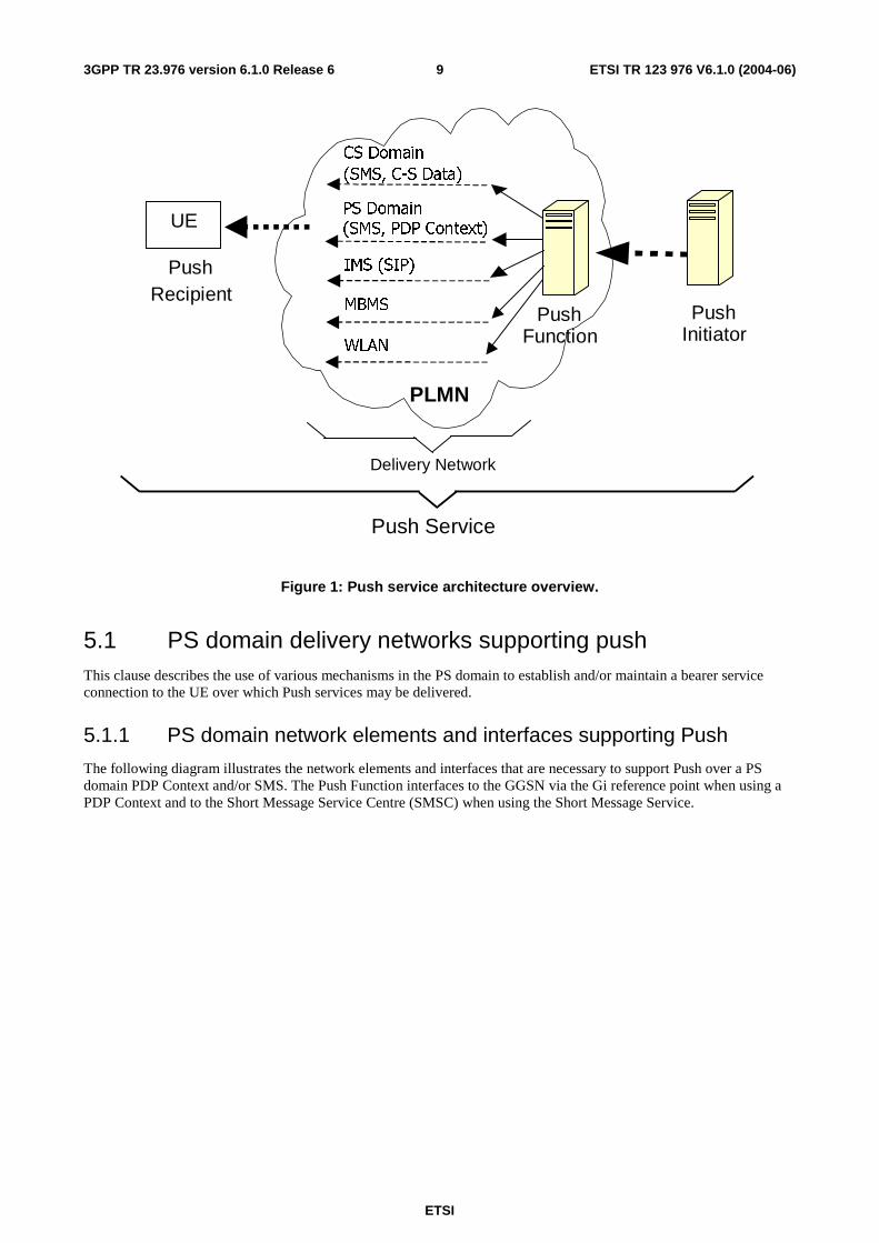
5 Push architecture overview The Push service architecture overview is shown in figure 1. This includes the push Application Servers, Push Function (or Push proxy) and Push Initiator as well as the delivery networks available and the Push Recipient or UE. The definition of functions in the Push Function (Push Proxy) and Push Initiator are outside the scope of this TR. Figure 1 also shows the Push Function performing delivery network selection; the definition of how this is performed and the criteria for delivery network selection are part of the definition of the Push Function and are outside the scope of this TR. Figure 1 depicts the Push Function being located within the PLMN: this is a logical representation of the Push service architecture and does not imply the physical collocation of a Push Function within the PLMN infrastructure.
The description of the delivery network used to support push services and how those delivery network services are established, maintained and withdrawn is the main focus of this clause.
ETSI
ETSI TR 123 976 V6.1.0 (2004-06) 9 3GPP TR 23.976 version 6.1.0 Release 6
PLMN
Push
Recipient
UE
Push Initiator
Push Service
Push Function
CS Domain (SMS, C-S Data)
PS Domain (SMS, PDP Context)
IMS (SIP)
Delivery Network
MBMS
WLAN
Figure 1: Push service architecture overview.
5.1 PS domain delivery networks supporting push This clause describes the use of various mechanisms in the PS domain to establish and/or maintain a bearer service connection to the UE over which Push services may be delivered.
5.1.1 PS domain network elements and interfaces supporting Push
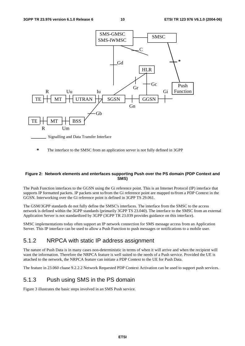
The following diagram illustrates the network elements and interfaces that are necessary to support Push over a PS domain PDP Context and/or SMS. The Push Function interfaces to the GGSN via the Gi reference point when using a PDP Context and to the Short Message Service Centre (SMSC) when using the Short Message Service.
ETSI
ETSI TR 123 976 V6.1.0 (2004-06) 103GPP TR 23.976 version 6.1.0 Release 6
Uu
Um
Gi
Gn
Iu Gc
Signalling and Data Transfer Interface
TE MT UTRAN
Push Function
Gr
HLR
SGSN
Gd
SMSC SMS - GMSC
SMS - IWMSC
GGSN
Gb
TE MT BSS
R
R
*
* The interface to the SMSC from an application server is not fully defined in 3GPP
C
Figure 2: Network elements and enterfaces supporting Push over the PS domain (PDP Context and SMS)
The Push Function interfaces to the GGSN using the Gi reference point. This is an Internet Protocol (IP) interface that supports IP formatted packets. IP packets sent to/from the Gi reference point are mapped to/from a PDP Context in the GGSN. Interworking over the Gi reference point is defined in 3GPP TS 29.061.
The GSM/3GPP standards do not fully define the SMSC's interfaces. The interface from the SMSC to the access network is defined within the 3GPP standards (primarily 3GPP TS 23.040). The interface to the SMSC from an external Application Server is not standardized by 3GPP (3GPP TR 23.039 provides guidance on this interface).
SMSC implementations today often support an IP network connection for SMS message access from an Application Server. This IP interface can be used to allow a Push Function to push messages or notifications to a mobile user.
5.1.2 NRPCA with static IP address assignment
The nature of Push Data is in many cases non-deterministic in terms of when it will arrive and when the recipient will want the information. Therefore the NRPCA feature is well suited to the needs of a Push service. Provided the UE is attached to the network, the NRPCA feature can initiate a PDP Context to the UE for Push Data.
The feature in 23.060 cluase 9.2.2.2 Network Requested PDP Context Activation can be used to support push services.
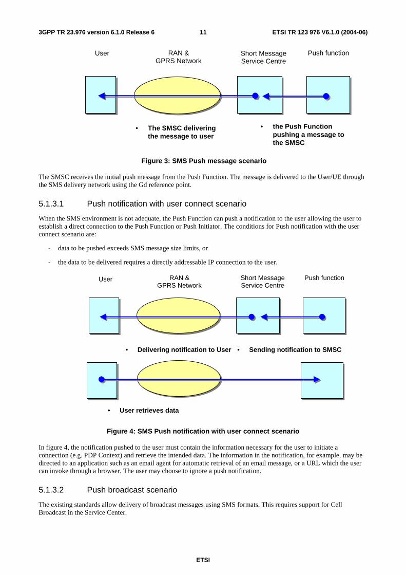
5.1.3 Push using SMS in the PS domain
Figure 3 illustrates the basic steps involved in an SMS Push service.
ETSI
ETSI TR 123 976 V6.1.0 (2004-06) 113GPP TR 23.976 version 6.1.0 Release 6
User RAN & GPRS Network
Push function
• the Push Function pushing a message to the SMSC
• The SMSC delivering the message to user
Short Message Service Centre
Figure 3: SMS Push message scenario
The SMSC receives the initial push message from the Push Function. The message is delivered to the User/UE through the SMS delivery network using the Gd reference point.
5.1.3.1 Push notification with user connect scenario
When the SMS environment is not adequate, the Push Function can push a notification to the user allowing the user to establish a direct connection to the Push Function or Push Initiator. The conditions for Push notification with the user connect scenario are:
- data to be pushed exceeds SMS message size limits, or
- the data to be delivered requires a directly addressable IP connection to the user.
User RAN & GPRS Network
Push function
• Sending notification to SMSC • Delivering notification to User
Short Message Service Centre
• User retrieves data
Figure 4: SMS Push notification with user connect scenario
In figure 4, the notification pushed to the user must contain the information necessary for the user to initiate a connection (e.g. PDP Context) and retrieve the intended data. The information in the notification, for example, may be directed to an application such as an email agent for automatic retrieval of an email message, or a URL which the user can invoke through a browser. The user may choose to ignore a push notification.
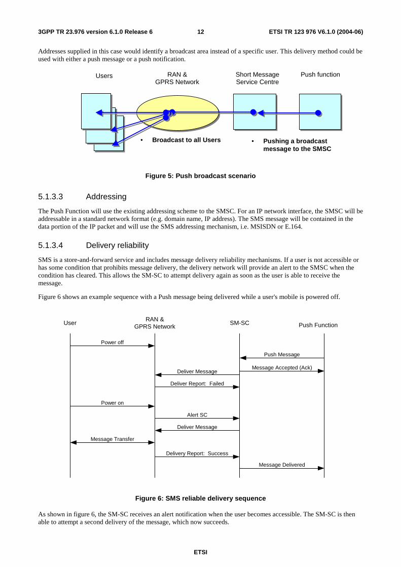
5.1.3.2 Push broadcast scenario
The existing standards allow delivery of broadcast messages using SMS formats. This requires support for Cell Broadcast in the Service Center.
ETSI
ETSI TR 123 976 V6.1.0 (2004-06) 123GPP TR 23.976 version 6.1.0 Release 6
Addresses supplied in this case would identify a broadcast area instead of a specific user. This delivery method could be used with either a push message or a push notification.
Users RAN & GPRS Network
Push function
• Pushing a broadcast message to the SMSC
• Broadcast to all Users
Short Message Service Centre
Figure 5: Push broadcast scenario
5.1.3.3 Addressing
The Push Function will use the existing addressing scheme to the SMSC. For an IP network interface, the SMSC will be addressable in a standard network format (e.g. domain name, IP address). The SMS message will be contained in the data portion of the IP packet and will use the SMS addressing mechanism, i.e. MSISDN or E.164.
5.1.3.4 Delivery reliability
SMS is a store-and-forward service and includes message delivery reliability mechanisms. If a user is not accessible or has some condition that prohibits message delivery, the delivery network will provide an alert to the SMSC when the condition has cleared. This allows the SM-SC to attempt delivery again as soon as the user is able to receive the message.
Figure 6 shows an example sequence with a Push message being delivered while a user's mobile is powered off.
UserRAN &
GPRS Network Push Function
Power on
Message Transfer
Push Message
SM-SC
Deliver Message
Deliver Report: Failed
Power off
Alert SC
Deliver Message
Delivery Report: Success
Message Accepted (Ack)
Message Delivered
Figure 6: SMS reliable delivery sequence
As shown in figure 6, the SM-SC receives an alert notification when the user becomes accessible. The SM-SC is then able to attempt a second delivery of the message, which now succeeds.
ETSI
ETSI TR 123 976 V6.1.0 (2004-06) 133GPP TR 23.976 version 6.1.0 Release 6
The Alert SMSC message is provided by the HLR/HSS per the existing SMS service definition TS 23.040.
The reliable delivery feature of SMS would also apply to the "Push notification with user connect scenario".
It is also possible for the SMSC to relay alert notices to the Push Function. In this case, the Push Function would be responsible for maintaining a copy of the message and re-transmitting when the user becomes available.
5.1.4 Push using Long-Lived PDP Context
A long-lived PDP Context is a good mechanism for timely delivery of Push Data, and where the user is receiving data on a frequent basis a long-lived PDP Context is also an efficient use of network resources. The existing definition of a PDP Context in TS 23.060 does not specify a maximum time limit for a PDP Context to be active before it must be deactivated. In theory, all PDP Contexts are long-lived (always-on) where their activation and deactivation are determined by the user and/or application.
In practice, networks may temporarily deactivate PDP Contexts for various reasons, such as network maintenance or after long periods where the PDP Context has not carried traffic. When a PDP Context is deactivated by the network, the Push Function needs to know the PDP Context is no longer available so it does not continue to use it for Push Data.
In the case where the PDP Context is deactivated by the network, there are different mechanisms that may be deployed to inform the Push Function of the PDP Context deactivation or to avoid the PDP context deactivation. These mechanisms are listed and discussed in the following subclauses.
5.1.4.1 Internet Control Message Protocol
The Internet Control Message Protocol (ICMP) is defined in IETF RFC 792. TS 23.060 clause 9.1.1 makes reference to the use of ICMP error notifications sent from the GGSN when a mobile-terminated IP packet is received in the INACTIVE state, indicating the PDP Context is deactivated.
ICMP error notification messages are sent from the GGSN when the GGSN is unable to forward an IP packet to its destination. Therefore the Push Function must generate an IP packet towards the UE before it will receive an ICMP message informing it that the packet is not deliverable. In this scenario the GGSN and Push Function may be unsynchronized for some period when the PDP Context is deactivated at the GGSN, and when the Push Function transmits an IP packet to the deactivated PDP Context and receives back an ICMP message.
When using ICMP as the mechanism to inform the Push Function that a PDP Context has been deactivated, the Push Function may need to send an IP packet to the UE before re-allocation of an IP address to another PDP Context. This is to guard against a Push Function transmitting an IP packet using an IP address that had been previously used by a PDP Context that has been deactivated and then re-assigned to a new PDP Context before the Push Function learned (via ICMP) of the deactivation of the first PDP Context. Sending Push Data to a wrong UE can only be avoided by sending an IP packet to each UE once in the time period that a GGSN is not using the IP addresses before allocation to another UE.
It is for further study whether ICMP support at the GGSN may apply to all APNs serviced by the GGSN, or on a per APN basis.
5.1.4.2 PDP Context State Notification message
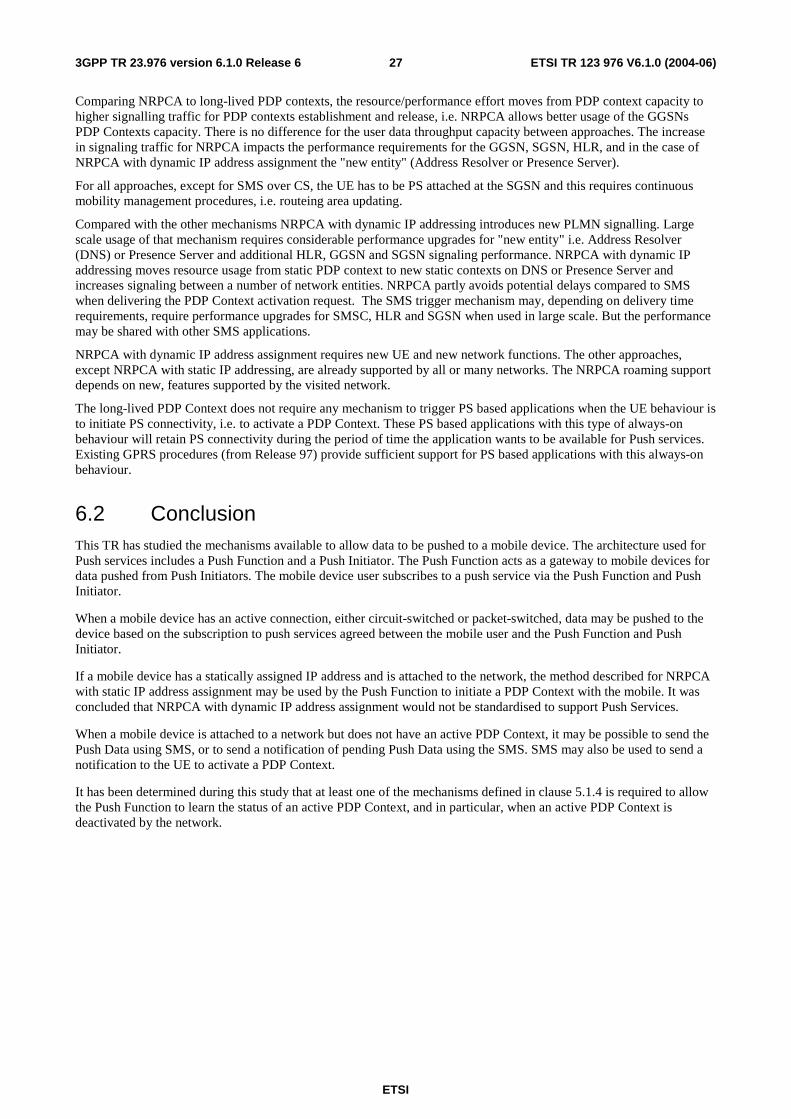
The GGSN, upon deactivation of a PDP Context, shall generate a PDP Context State Notification message towards the Push Function using an address configured in the GGSN PDP Context state information.
The support of this message by the GGSN shall be configurable on a per APN basis. The format of a PDP Context State Notification message shall include the deactivated PDP Context MSISDN, PDP Address, and APN.
By generating a PDP Context State Notification message when the PDP Context is deactivated the GGSN and Push Function are kept synchronized with respect to the state of the PDP Context. Given a Notification message will be generated for each PDP Context associated with a given APN configured to use this feature, this will generate extra traffic over the Gi Reference point. In addition, not all PDP Contexts associated with an APN are used for Push service, yet all PDP Contexts associated with an APN using this feature will have a Notification message generated when they are deactivated.
The PDP Context State Notification message is not currently defined in 3G/GSM specifications. Annex A provides an example mechanism for implementing this feature.
ETSI
ETSI TR 123 976 V6.1.0 (2004-06) 143GPP TR 23.976 version 6.1.0 Release 6
5.1.4.3 Radius Accounting START/STOP messages
Although the use of Radius is not mandatory in 3GPP networks it is widely deployed. Radius is an Authorization, Authentication, and Accounting service that may also take on the function of IP address allocation (like DHCP), see TS 29.061. The Radius Accounting START/STOP messages have a side effect of indicating when a PDP Context is activated and deactivated. A Radius server by using the information collected as a result of Accounting START/STOP messages can inform the Push Function on the state of a PDP Context.
The interworking of a Push Function to a Radius server is outside the scope of the present document.
5.1.4.4 COPS DRQ operation
The COPS protocol operates between the GGSN and the PDF over the Go reference point. TS 23.207 clause 5.3 describes the Go interface and the COPS messages exchanged over it, including the Delete Request State (DRQ) message. TS 23.207 clause 6.3.2 describes how the COPS DRQ message is used to indicate the release of a PDP Context to the PDF. In TR 23.917 section 8.10 shows when a PDP Context is deactivated at the GGSN a COPS DRQ message is sent to the PDF. The PDF upon receipt of the COPS DRQ message may forward an indication to an application function over the Gq reference point indicating that network resources have been removed. This mechanism could be used to indicate to a Push Function that a PDP Context has been deactivated. Gq is being defined as part of Release 6.
5.1.4.5 Keep alive messages
Most networks set a maximum time for a PDP Context to be open and idle, after which the PDP Context is dropped. But upon deactivation no message is sent to the Application Server to inform it that a PDP Context is unavailable. To prevent this from happening an Application Server may simulate network traffic by periodically sending a keep alive message over the PDP Context to ensure the idle timer in the network is reset and the PDP Context remains open.
The use of keep alive messages consumes network resources and counters the operators' attempts to properly manage its network resources e.g. the number of available PDP Contexts. This TR explores mechanisms where the network can report the state of a PDP Context to the Application Server, particularly when a PDP Context is deactivated. These mechanisms use substantially less network resources than those required for keep alive messages, and provide the same information to the Push Function.
The use of keep alive messages is not encouraged and instead one or more of the methods described in this clause should be used to maintain synchronization of the Push Function with the state of the PDP Context in the network.
5.1.4.6 PDP context re-establishment
When the network deactivates the PDP context the UE re-establishes a PDP context as long as a push user agent is active on the UE. This is performed when the deactivation cause allows it, e.g. if the PDP context is not deactivated because of "operator determined barring". It may be useful to introduce a specific release cause that clearly indicates that PDP context re-establishment is allowed, or it may be recommended that networks indicate the exiting release cause "re-establishment context required" when PDP contexts are released and re-establishment is allowed.
5.1.4.7 Presence information
The GGSN informs a presence server when PDP contexts are activated or deactivated. The Push Function derives status information from the presence server before data push or the presence server informs the Push Function when status information changes, i.e. when the PDP context is deactivated.
5.1.4.8 Comparison
The mechanisms described above for the long-lived PDP context have different impact on availability of UEs to receive Push Data and require different functionality.
The ICMP approach may be used similarly to keep alive messages, enabling the Push Function to discover when the PDP context is no longer allocated. This polling of the UE causes some waste of resources as a packet is sent to the UE if the IP address is allocated to a PDP context. As an alternative to polling ICMP may be used to indicate only that an IP address is no longer allocated to a UE. In this case there the risk that the Push Function sends Push Data to a wrong UE.
ETSI
ETSI TR 123 976 V6.1.0 (2004-06) 153GPP TR 23.976 version 6.1.0 Release 6
Four different approaches inform the Push Function when a PDP context is deactivated. The Radius, the COPS and the Presence approach are already specified or under specification and all these are for wider use by various applications. The PDP Context State Notification approach identified no commonly used protocol yet. Under the assumption that this is a specific interface and protocol for the Push Function and not an already introduced protocol one of the already specified approaches are preferable.
From a user point of view it may be preferable to maintain the UE's ability to receive Push Data. In this case the re-establishment of a PDP context is the preferred approach to react on network requested PDP context deactivation.
5.1.5 NRPCA with dynamic IP address assignment
The use of NRPCA with dynamic IP address assignment is currently not defined in 3G specifications. What follows are two possible technical solutions to this issue.
5.1.5.1 NRPCA with one GGSN per Push service APN
This solution assumes the OMA/WAP Push architecture and protocols are in use where the Push client on the UE has previously subscribed to a Push service offered via the Push Function. Therefore the Push Data arriving over the PDP Context (created as a result of the NRPCA) can be directed to the appropriate client application on the UE. It is assumed the UE is willing to accept all incoming Request PDP Context Activations.
One of the issues with defining a mechanism to support NRPCA is the complexity required to support the establishment of a PDP Context where the selection of a GGSN results in a different GGSN from that which originated the NRPCA request. The complexity of the NRPCA solution is greatly reduced if the Create PDP Context Request always resolves back to the home (originating) GGSN. The solution proposed in this section restricts the support of an APN for Push services to being serviced by only one GGSN. This ensures the PDP Context is created at the originating GGSN and thus simplifies the solution for NRPCA. In this solution there is only one GGSN that can serve an APN supporting the Push Function.
The Address Resolver (AR) is implemented using DNS and the User-ID is a unique name in the format user@realm and therefore any query to any Address Resolver in the network will always end up at the home AR for the User-ID.
This proposal requires one change to the SGSN. In step 4 the PDU Notification Request will contain a null PDP Address. The SGSN must be modified to accept this field as null and forward the Request PDP Context Activation message to the UE with a null PDP Address field. The UE upon receiving a Request PDP Context Activation with a null PDP Address field will use this as an indicator to establish a PDP Context back to the APN contained in the Request PDP Context Activation.
Since the APN for the Push Function is only served by one GGSN this will remove the ability to share the load (load balancing) of Push traffic across a number of GGSNs using the GGSN selection mechanism defined in 3G specifications. But it should be noted there is no limitation on allowing multiple APNs, each supporting the Push Function, where each APN is served by a different GGSN. Configuring these GGSN/APN pairs would be a way of achieving load balancing by assigning APNs for Push such as Push1.operator.com, Push2.operator.com etc. A Push Function that selects a GGSN for NRPCA would use only the APN supported by that GGSN in its request. If multiple GGSN/APN pairs are available to serve a Push Function, the Push Function would use some algorithm (i.e. round robin) to select a GGSN to initiate a NRPCA. This would allow the load of Push traffic to be shared across multiple GGSNs achieving the effect of load balancing. A mechanism to ensure that multiple PDP Contexts to the same UE are not established is for further study.
ETSI
ETSI TR 123 976 V6.1.0 (2004-06) 163GPP TR 23.976 version 6.1.0 Release 6
Visited or Home Network Home Network
12. Push Confirm
13. push data transfer Push
Data
SGSN
4. PDU Notification Request
5. PDU Notification Response
8. Create PDP Context Request
9. Create PDP Context Response
HLR GGSN AddrRes PF
1. Push-Message
2. Push Request
3. Query AR
3a. Push Confirm
3b. Send Routeing Info
11. Update AR 10. Activate PDP Context Accept
6. Request PDP Context Activation
7. Activate PDP Context Request
PI UE
Note1: Solid arrow means Message type currently defined in 3G specifications Note2: Square arrow means Message type not currently defined in 3G specifications Note3: Long dash dot arrow means Message type defined in OMA Push specifications Push Access Protocol
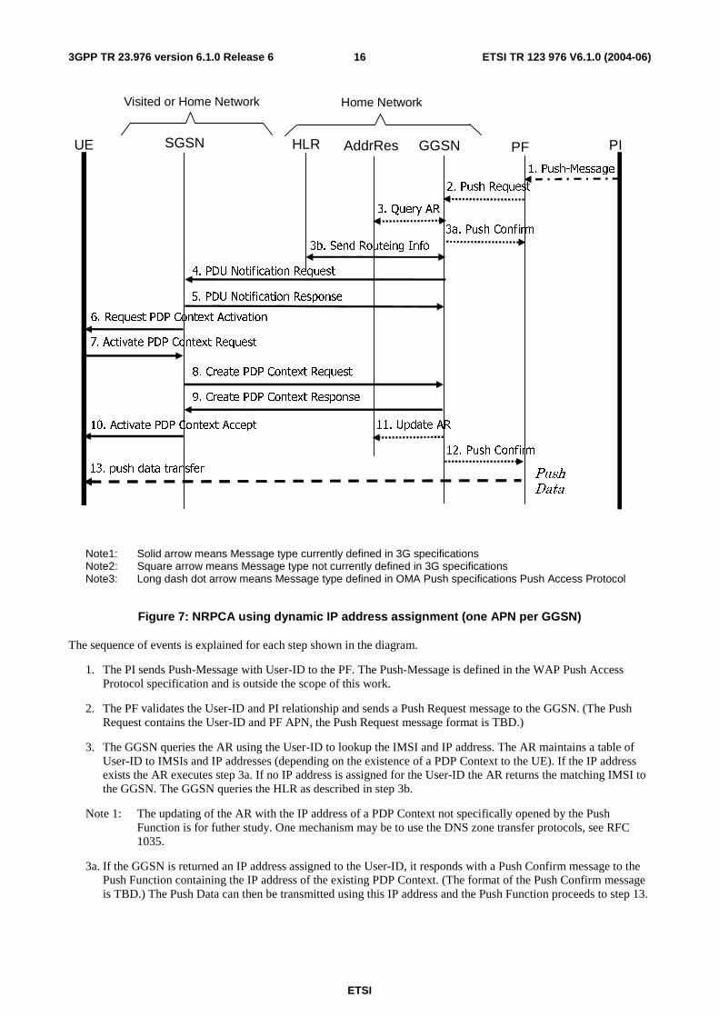
Figure 7: NRPCA using dynamic IP address assignment (one APN per GGSN)
The sequence of events is explained for each step shown in the diagram.
1. The PI sends Push-Message with User-ID to the PF. The Push-Message is defined in the WAP Push Access Protocol specification and is outside the scope of this work.
2. The PF validates the User-ID and PI relationship and sends a Push Request message to the GGSN. (The Push Request contains the User-ID and PF APN, the Push Request message format is TBD.)
3. The GGSN queries the AR using the User-ID to lookup the IMSI and IP address. The AR maintains a table of User-ID to IMSIs and IP addresses (depending on the existence of a PDP Context to the UE). If the IP address exists the AR executes step 3a. If no IP address is assigned for the User-ID the AR returns the matching IMSI to the GGSN. The GGSN queries the HLR as described in step 3b.
Note 1: The updating of the AR with the IP address of a PDP Context not specifically opened by the Push Function is for futher study. One mechanism may be to use the DNS zone transfer protocols, see RFC 1035.
3a. If the GGSN is returned an IP address assigned to the User-ID, it responds with a Push Confirm message to the Push Function containing the IP address of the existing PDP Context. (The format of the Push Confirm message is TBD.) The Push Data can then be transmitted using this IP address and the Push Function proceeds to step 13.
ETSI
ETSI TR 123 976 V6.1.0 (2004-06) 173GPP TR 23.976 version 6.1.0 Release 6
Note 2: The presence of an IP address in the AR table does not necessarily imply an existing PDP Context. If the UE uses static IP addressing the AR would have a permanent entry in its table for that UEs User-ID, but the UE may not have an active PDP Context at the time the Push Data is sent to the UE. In this case NRPCA using static IP addressing procedures as defined in TS 23.060 clause 9.2.2.2 would be executed at step 13.
3b. Using the IMSI matching the User-ID, the GGSN obtains routeing information for the UE by issuing Send Routeing Information request to the HLR. The HLR returns the address of the SGSN to which the UE is currently attached.
4. The GGSN sends a PDU Notification Request to the SGSN identified in step 3b with a null IP Address. The PDP Notification Request contains the fields; IMSI, Tunnel Endpoint Identifier Control Plane, End User Address, APN, GGSN Address for Control Plane, and Private Extension. An extension to TS 29.060 is required to allow the End User Address (PDP Address) to be null, indicating the UE is to request a dynamically assigned IP address.
Note 3: An alternative to sending the null PDP Address may be to send a PDU Notification Request to the SGSN using a reserved IP address in the PDP Address field to avoid changes needed at the SGSN to implement the NRPCA feature.
5. The GGSN receives a successful PDU Notification Response from the SGSN.
6. The SGSN sends Request PDP Context Activation (TI, PDP Type, PDP Address, APN) to UE, with a null PDP Address.
7. The UE sends Activate PDP Context Request to the SGSN with the null IP address and APN obtained from the Request PDP Context Activation.
8. The SGSN sends the GGSN (in the home network) a Create PDP Context Request. Since the APN used for the Push Function is only served by the home GGSN, the SGSN will always select the home GGSN to create the PDP Context. The GGSN obtains a dynamically assigned IP address (eg from a DHCP server, Radius server or address pool).
9. The GGSN sends the SGSN a Create PDP Context Response which may contain the parameters; Cause, Reordering required, Recovery, Tunnel Endpoint Identifier Data I, Tunnel Endpoint Identifier Control Plane, Charging ID, End User Address, Protocol Configuration Options, GGSN Address for Control Plane, GGSN Address for user traffic, Quality of Service Profile, Charging Gateway Address.
10. After successful PDP Context creation the SGSN sends Activate PDP Context Accept to the UE with the assigned IP address.
11. After the GGSN sends the Create PDP Context Response in step 9 it will update the AR with an Update AR message, updating the entry for the IMSI and User-Id with the IP address for the activated PDP Context.
12. The GGSN sends a Push Confirm message to the PF with the newly assigned IP Address.
13. The Push Function sends the Push Data in IP packets using the IP address from the Push Confirm.
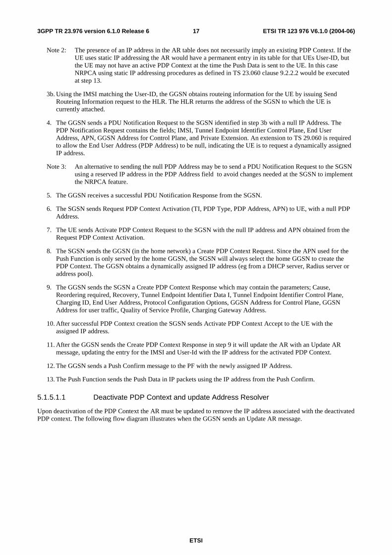
5.1.5.1.1 Deactivate PDP Context and update Address Resolver
Upon deactivation of the PDP Context the AR must be updated to remove the IP address associated with the deactivated PDP context. The following flow diagram illustrates when the GGSN sends an Update AR message.
ETSI
ETSI TR 123 976 V6.1.0 (2004-06) 183GPP TR 23.976 version 6.1.0 Release 6
GGSN
1 ) Update AR
Delete PDP Context Request
Address Resolver
SGSN
Delete PDP Context Response
Figure 8: Deactivate PDP Context and update Address Resolver (at home GGSN)
1) After the GGSN issues a Delete PDP Context Response message it will generate an Update AR message towards the AR containing an indication the IP address of the deleted PDP context must be removed from the AR tables.
5.1.5.1.2 Address Resolver and User-ID
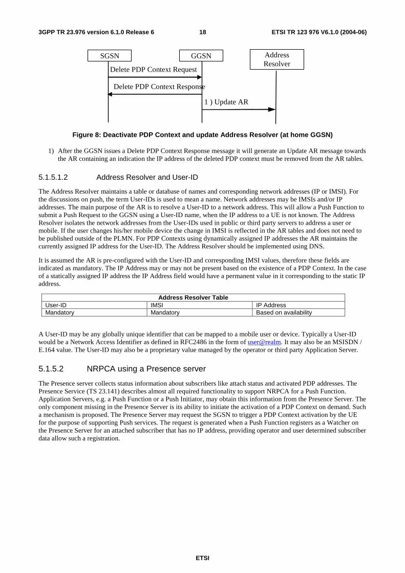
The Address Resolver maintains a table or database of names and corresponding network addresses (IP or IMSI). For the discussions on push, the term User-IDs is used to mean a name. Network addresses may be IMSIs and/or IP addresses. The main purpose of the AR is to resolve a User-ID to a network address. This will allow a Push Function to submit a Push Request to the GGSN using a User-ID name, when the IP address to a UE is not known. The Address Resolver isolates the network addresses from the User-IDs used in public or third party servers to address a user or mobile. If the user changes his/her mobile device the change in IMSI is reflected in the AR tables and does not need to be published outside of the PLMN. For PDP Contexts using dynamically assigned IP addresses the AR maintains the currently assigned IP address for the User-ID. The Address Resolver should be implemented using DNS.
It is assumed the AR is pre-configured with the User-ID and corresponding IMSI values, therefore these fields are indicated as mandatory. The IP Address may or may not be present based on the existence of a PDP Context. In the case of a statically assigned IP address the IP Address field would have a permanent value in it corresponding to the static IP address.
Address Resolver Table User-ID IMSI IP Address Mandatory Mandatory Based on availability
A User-ID may be any globally unique identifier that can be mapped to a mobile user or device. Typically a User-ID would be a Network Access Identifier as defined in RFC2486 in the form of user@realm. It may also be an MSISDN / E.164 value. The User-ID may also be a proprietary value managed by the operator or third party Application Server.
5.1.5.2 NRPCA using a Presence server
The Presence server collects status information about subscribers like attach status and activated PDP addresses. The Presence Service (TS 23.141) describes almost all required functionality to support NRPCA for a Push Function. Application Servers, e.g. a Push Function or a Push Initiator, may obtain this information from the Presence Server. The only component missing in the Presence Server is its ability to initiate the activation of a PDP Context on demand. Such a mechanism is proposed. The Presence Server may request the SGSN to trigger a PDP Context activation by the UE for the purpose of supporting Push services. The request is generated when a Push Function registers as a Watcher on the Presence Server for an attached subscriber that has no IP address, providing operator and user determined subscriber data allow such a registration.
ETSI
ETSI TR 123 976 V6.1.0 (2004-06) 193GPP TR 23.976 version 6.1.0 Release 6
2. Subscribe
PF
5. PDP Context Activation Procedure
No IP address known
PS GGSN SGSN UE
3. Request PDP Context Activation
4. Request PDP Context Activation
6. Notification
7. Notification
8. push data
1. Push-Message
PI
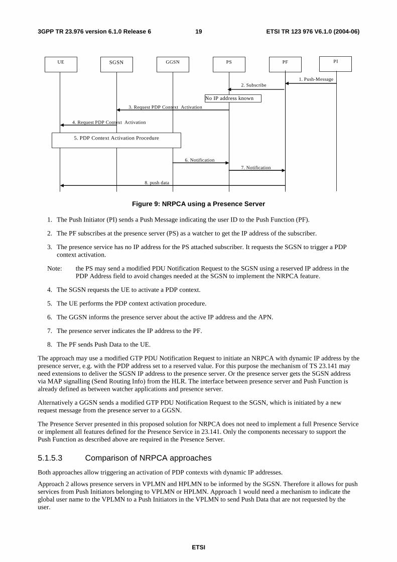
Figure 9: NRPCA using a Presence Server
1. The Push Initiator (PI) sends a Push Message indicating the user ID to the Push Function (PF).
2. The PF subscribes at the presence server (PS) as a watcher to get the IP address of the subscriber.
3. The presence service has no IP address for the PS attached subscriber. It requests the SGSN to trigger a PDP context activation.
Note: the PS may send a modified PDU Notification Request to the SGSN using a reserved IP address in the PDP Address field to avoid changes needed at the SGSN to implement the NRPCA feature.
4. The SGSN requests the UE to activate a PDP context.
5. The UE performs the PDP context activation procedure.
6. The GGSN informs the presence server about the active IP address and the APN.
7. The presence server indicates the IP address to the PF.
8. The PF sends Push Data to the UE.
The approach may use a modified GTP PDU Notification Request to initiate an NRPCA with dynamic IP address by the presence server, e.g. with the PDP address set to a reserved value. For this purpose the mechanism of TS 23.141 may need extensions to deliver the SGSN IP address to the presence server. Or the presence server gets the SGSN address via MAP signalling (Send Routing Info) from the HLR. The interface between presence server and Push Function is already defined as between watcher applications and presence server.
Alternatively a GGSN sends a modified GTP PDU Notification Request to the SGSN, which is initiated by a new request message from the presence server to a GGSN.
The Presence Server presented in this proposed solution for NRPCA does not need to implement a full Presence Service or implement all features defined for the Presence Service in 23.141. Only the components necessary to support the Push Function as described above are required in the Presence Server.
5.1.5.3 Comparison of NRPCA approaches
Both approaches allow triggering an activation of PDP contexts with dynamic IP addresses.
Approach 2 allows presence servers in VPLMN and HPLMN to be informed by the SGSN. Therefore it allows for push services from Push Initiators belonging to VPLMN or HPLMN. Approach 1 would need a mechanism to indicate the global user name to the VPLMN to a Push Initiators in the VPLMN to send Push Data that are not requested by the user.
ETSI
ETSI TR 123 976 V6.1.0 (2004-06) 203GPP TR 23.976 version 6.1.0 Release 6
Approach 2 informs the Push Function when a subscriber may be reached, e.g. when PDP context activation or PS attach are performed. Approach 1 would periodically request the IP address or a PDP establishment when Push Data should be delivered but the UE is not reachable.
Approach 1 introduces new interfaces and protocols between Push Function and GGSN and between GGSN and Address Resolver. The only new element of approach 2 is a request from the Presence Server to the SGSN to initiate a PDP context activation.
In comparison to approach 1 approach 2 can Push Data also via PDP contexts established on GGSNs in visited networks.
Approach 2 may use service control defined for presence service to allow subscriber controlling which push services may send data or initiate PDP context activation.
In comparison to the simplified approach 1 approach 2 is not limited to only one GGSN for one APN. A variant of Approach 1 in Annex B describes an approach 1, which may use multiple GGSNs per APN. This requires additional functionality on SGSN and GGSN.
Each approach relies on a new network entity. It is an implementation option whether the Address Resolver or the presence server are implemented on the already introduced entities Domain Name Service or Presence Server.
5.2 CS domain delivery networks supporting Push This clause describes the use of various mechanisms in the CS domain to establish and/or maintain a bearer service connection to the UE over which Push services may be delivered.
5.2.1 CS domain network elements and interfaces supporting Push
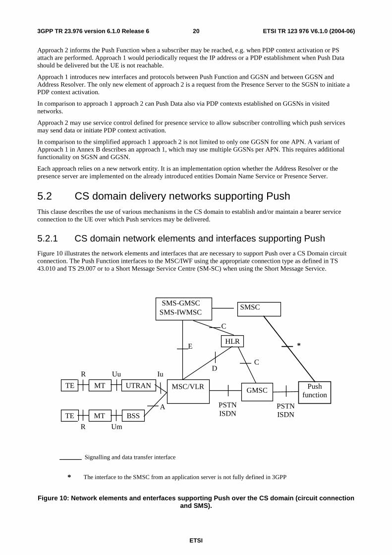
Figure 10 illustrates the network elements and interfaces that are necessary to support Push over a CS Domain circuit connection. The Push Function interfaces to the MSC/IWF using the appropriate connection type as defined in TS 43.010 and TS 29.007 or to a Short Message Service Centre (SM-SC) when using the Short Message Service.
Uu
Um
Iu
Signalling and data transfer interface
TE MT UTRAN Push function
D
HLR
MSC/VLR
E
SMSC SMS - GMSC SMS - IWMSC
A TE MT BSS
R
R
*
* The interface to the SMSC from an application server is not fully defined in 3GPP
C
PSTN ISDN
GMSC
C
PSTN ISDN
Figure 10: Network elements and enterfaces supporting Push over the CS domain (circuit connection and SMS).
ETSI
ETSI TR 123 976 V6.1.0 (2004-06) 213GPP TR 23.976 version 6.1.0 Release 6
The Push Function interfaces to the MSC/IWF to transmit and receive circuit-switched data traffic. This interface may operate over a PSTN, ISDN or PDN. The MSC/IWF will perform the appropriate conversion for the connection type operating between the MSC/IWF and the Push Function to support data traffic over a GSM/3G PLMN circuit connection to the UE.
The interface between the Push Function and the SMSC is the same as that described in clause 5.1.1 above.
5.2.2 Push using SMS in the CS domain
Push using SMS in the CS domain operates as described in clause 5.1.3, SMS messages are delivered to the UE using the A or Iu reference point.
5.3 IMS delivery networks supporting Push This clause describes methods using the SIP protocol in IMS to carry Push services to a UE.
5.3.1 IMS network elements and interfaces supporting Push
The IMS architecture is described in TS 23.228. The multimedia call control protocol in IMS is described in TS 24.229.
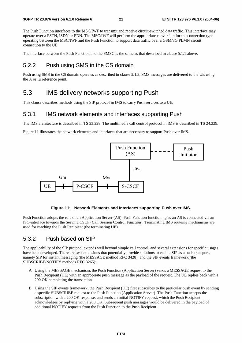
Figure 11 illustrates the network elements and interfaces that are necessary to support Push over IMS.
UE P-CSCF S-CSCF
Push Function (AS)
Push Initiator
ISC
Gm Mw
Figure 11: Network Elements and Interfaces supporting Push over IMS.
Push Function adopts the role of an Application Server (AS). Push Function functioning as an AS is connected via an ISC-interface towards the Serving CSCF (Call Session Control Function). Terminating IMS routeing mechanisms are used for reaching the Push Recipient (the terminating UE).
5.3.2 Push based on SIP
The applicability of the SIP protocol extends well beyond simple call control, and several extensions for specific usages have been developed. There are two extensions that potentially provide solutions to enable SIP as a push transport, namely SIP for instant messaging (the MESSAGE method RFC 3428), and the SIP events framework (the SUBSCRIBE/NOTIFY methods RFC 3265):
A Using the MESSAGE mechanism, the Push Function (Application Server) sends a MESSAGE request to the Push Recipient (UE) with an appropriate push message as the payload of the request. The UE replies back with a 200 OK completing the transaction.
B Using the SIP events framework, the Push Recipient (UE) first subscribes to the particular push event by sending a specific SUBSCRIBE request to the Push Function (Application Server). The Push Function accepts the subscription with a 200 OK response, and sends an initial NOTIFY request, which the Push Recipient acknowledges by replying with a 200 OK. Subsequent push messages would be delivered in the payload of additional NOTIFY requests from the Push Function to the Push Recipient.
ETSI
ETSI TR 123 976 V6.1.0 (2004-06) 223GPP TR 23.976 version 6.1.0 Release 6
5.4 MBMS delivery networks supporting Push There are no stage 1 requirements defined at this time and therefore no stage 2 analysis has been done.
5.5 WLAN delivery networks supporting Push There are no stage 1 requirements defined at this time and therefore no stage 2 analysis has been done.
6 Analysis and conclusion
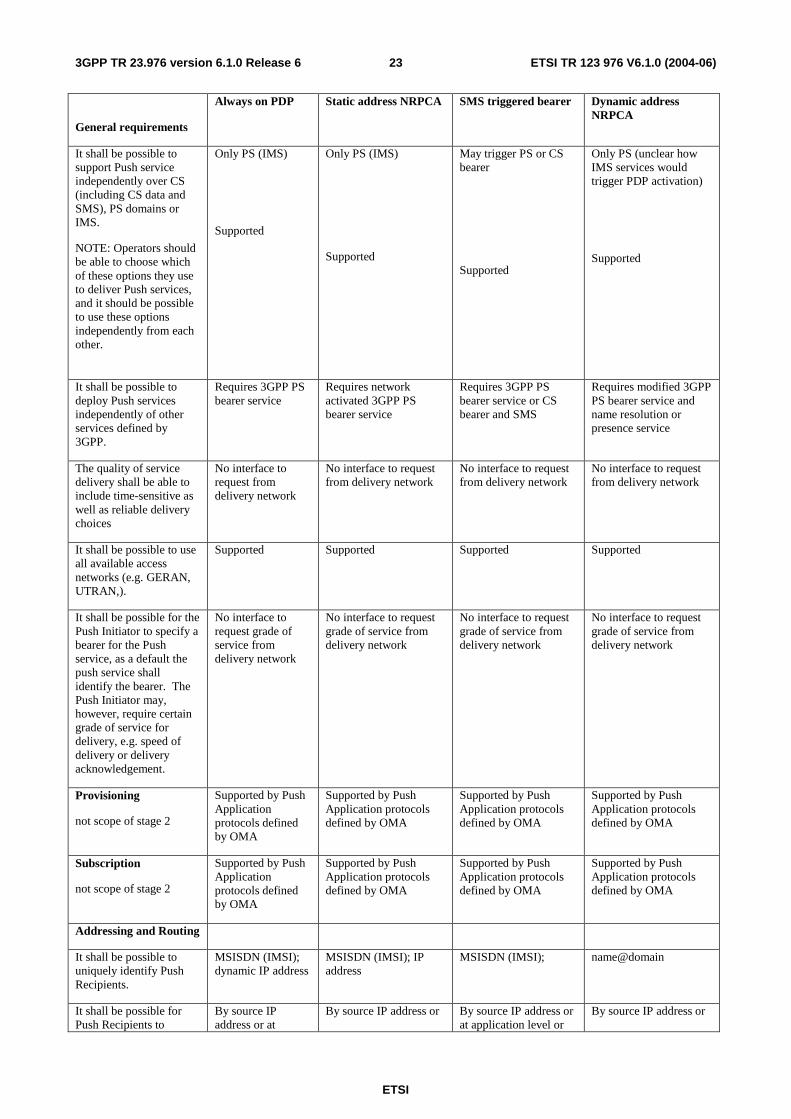
6.1 Comparison summary of Push requirements to Push mechanisms
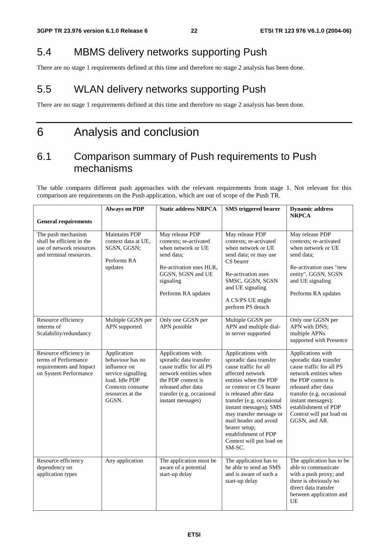
The table compares different push approaches with the relevant requirements from stage 1. Not relevant for this comparison are requirements on the Push application, which are out of scope of the Push TR.
General requirements
Always on PDP Static address NRPCA SMS triggered bearer Dynamic address NRPCA
The push mechanism shall be efficient in the use of network resources and terminal resources.
Maintains PDP context data at UE, SGSN, GGSN;
Performs RA updates
May release PDP contexts; re-activated when network or UE send data;
Re-activation uses HLR, GGSN, SGSN and UE signaling
Performs RA updates
May release PDP contexts; re-activated when network or UE send data; or may use CS bearer
Re-activation uses SMSC, GGSN, SGSN and UE signaling
A CS/PS UE might perform PS detach
May release PDP contexts; re-activated when network or UE send data;
Re-activation uses "new entity", GGSN, SGSN and UE signaling
Performs RA updates
Resource efficiency interms of Scalability/redundancy
Multiple GGSN per APN supported
Only one GGSN per APN possible
Multiple GGSN per APN and multiple dial-in server supported
Only one GGSN per APN with DNS; multiple APNs supported with Presence
Resource efficiency in terms of Performance requirements and Impact on System Performance
Application behaviour has no influence on service signalling load. Idle PDP Contexts consume resources at the GGSN.
Applications with sporadic data transfer cause traffic for all PS network entities when the PDP context is released after data transfer (e.g. occasional instant messages)
Applications with sporadic data transfer cause traffic for all affected network entities when the PDP or context or CS bearer is released after data transfer (e.g. occasional instant messages); SMS may transfer message or mail header and avoid bearer setup; establishment of PDP Context will put load on SM-SC.
Applications with sporadic data transfer cause traffic for all PS network entities when the PDP context is released after data transfer (e.g. occasional instant messages); establishment of PDP Context will put load on GGSN, and AR.
Resource efficiency dependency on application types
Any application The application must be aware of a potential start-up delay
The application has to be able to send an SMS and is aware of such a start-up delay
The application has to be able to communicate with a push proxy; and there is obviously no direct data transfer between application and UE
ETSI
ETSI TR 123 976 V6.1.0 (2004-06) 233GPP TR 23.976 version 6.1.0 Release 6
General requirements
Always on PDP Static address NRPCA SMS triggered bearer Dynamic address NRPCA
It shall be possible to support Push service independently over CS (including CS data and SMS), PS domains or IMS.
NOTE: Operators should be able to choose which of these options they use to deliver Push services, and it should be possible to use these options independently from each other.
Only PS (IMS)
Supported
Only PS (IMS)
Supported
May trigger PS or CS bearer
Supported
Only PS (unclear how IMS services would trigger PDP activation)
Supported
It shall be possible to deploy Push services independently of other services defined by 3GPP.
Requires 3GPP PS bearer service
Requires network activated 3GPP PS bearer service
Requires 3GPP PS bearer service or CS bearer and SMS
Requires modified 3GPP PS bearer service and name resolution or presence service
The quality of service delivery shall be able to include time-sensitive as well as reliable delivery choices
No interface to request from delivery network
No interface to request from delivery network
No interface to request from delivery network
No interface to request from delivery network
It shall be possible to use all available access networks (e.g. GERAN, UTRAN,).
Supported Supported Supported Supported
It shall be possible for the Push Initiator to specify a bearer for the Push service, as a default the push service shall identify the bearer. The Push Initiator may, however, require certain grade of service for delivery, e.g. speed of delivery or delivery acknowledgement.
No interface to request grade of service from delivery network
No interface to request grade of service from delivery network
No interface to request grade of service from delivery network
No interface to request grade of service from delivery network
Provisioning
not scope of stage 2
Supported by Push Application protocols defined by OMA
Supported by Push Application protocols defined by OMA
Supported by Push Application protocols defined by OMA
Supported by Push Application protocols defined by OMA
Subscription
not scope of stage 2
Supported by Push Application protocols defined by OMA
Supported by Push Application protocols defined by OMA
Supported by Push Application protocols defined by OMA
Supported by Push Application protocols defined by OMA
Addressing and Routing
It shall be possible to uniquely identify Push Recipients.
MSISDN (IMSI); dynamic IP address
MSISDN (IMSI); IP address
MSISDN (IMSI); name@domain
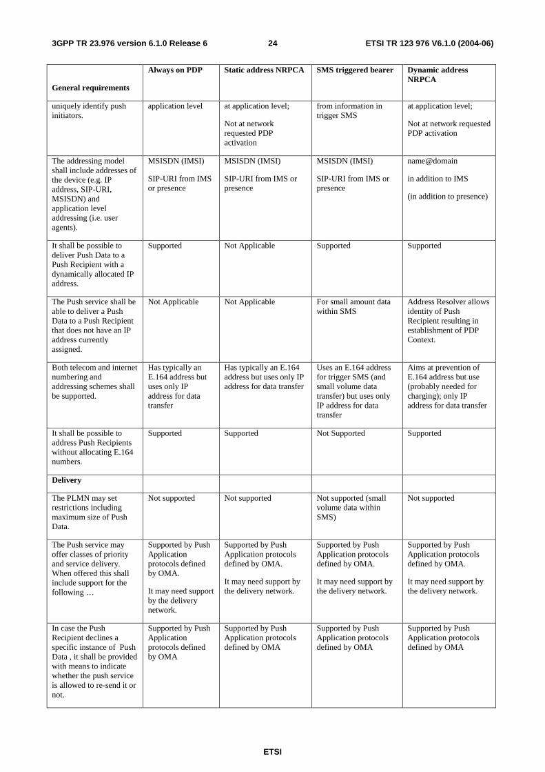
It shall be possible for Push Recipients to
By source IP address or at
By source IP address or By source IP address or at application level or
By source IP address or
ETSI
ETSI TR 123 976 V6.1.0 (2004-06) 243GPP TR 23.976 version 6.1.0 Release 6
General requirements
Always on PDP Static address NRPCA SMS triggered bearer Dynamic address NRPCA
uniquely identify push initiators.
application level at application level;
Not at network requested PDP activation
from information in trigger SMS
at application level;
Not at network requested PDP activation
The addressing model shall include addresses of the device (e.g. IP address, SIP-URI, MSISDN) and application level addressing (i.e. user agents).
MSISDN (IMSI)
SIP-URI from IMS or presence
MSISDN (IMSI)
SIP-URI from IMS or presence
MSISDN (IMSI)
SIP-URI from IMS or presence
name@domain
in addition to IMS
(in addition to presence)
It shall be possible to deliver Push Data to a Push Recipient with a dynamically allocated IP address.
Supported Not Applicable Supported Supported
The Push service shall be able to deliver a Push Data to a Push Recipient that does not have an IP address currently assigned.
Not Applicable Not Applicable For small amount data within SMS
Address Resolver allows identity of Push Recipient resulting in establishment of PDP Context.
Both telecom and internet numbering and addressing schemes shall be supported.
Has typically an E.164 address but uses only IP address for data transfer
Has typically an E.164 address but uses only IP address for data transfer
Uses an E.164 address for trigger SMS (and small volume data transfer) but uses only IP address for data transfer
Aims at prevention of E.164 address but use (probably needed for charging); only IP address for data transfer
It shall be possible to address Push Recipients without allocating E.164 numbers.
Supported Supported Not Supported Supported
Delivery
The PLMN may set restrictions including maximum size of Push Data.
Not supported Not supported Not supported (small volume data within SMS)
Not supported
The Push service may offer classes of priority and service delivery. When offered this shall include support for the following …
Supported by Push Application protocols defined by OMA.
It may need support by the delivery network.
Supported by Push Application protocols defined by OMA.
It may need support by the delivery network.
Supported by Push Application protocols defined by OMA.
It may need support by the delivery network.
Supported by Push Application protocols defined by OMA.
It may need support by the delivery network.
In case the Push Recipient declines a specific instance of Push Data , it shall be provided with means to indicate whether the push service is allowed to re-send it or not.
Supported by Push Application protocols defined by OMA
Supported by Push Application protocols defined by OMA
Supported by Push Application protocols defined by OMA
Supported by Push Application protocols defined by OMA
ETSI
ETSI TR 123 976 V6.1.0 (2004-06) 253GPP TR 23.976 version 6.1.0 Release 6
General requirements
Always on PDP Static address NRPCA SMS triggered bearer Dynamic address NRPCA
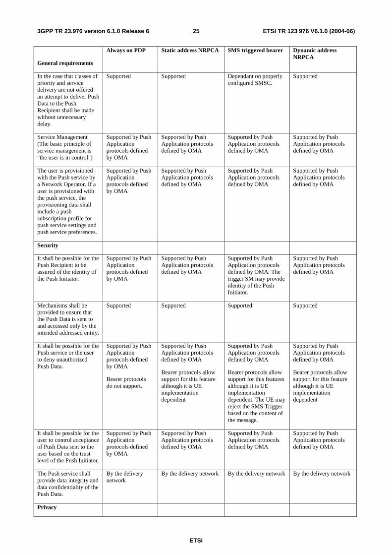
In the case that classes of priority and service delivery are not offered an attempt to deliver Push Data to the Push Recipient shall be made without unnecessary delay.
Supported Supported Dependant on properly configured SMSC.
Supported
Service Management (The basic principle of service management is "the user is in control")
Supported by Push Application protocols defined by OMA
Supported by Push Application protocols defined by OMA
Supported by Push Application protocols defined by OMA
Supported by Push Application protocols defined by OMA
The user is provisioned with the Push service by a Network Operator. If a user is provisioned with the push service, the provisioning data shall include a push subscription profile for push service settings and push service preferences.
Supported by Push Application protocols defined by OMA
Supported by Push Application protocols defined by OMA
Supported by Push Application protocols defined by OMA
Supported by Push Application protocols defined by OMA
Security
It shall be possible for the Push Recipient to be assured of the identity of the Push Initiator.
Supported by Push Application protocols defined by OMA
Supported by Push Application protocols defined by OMA
Supported by Push Application protocols defined by OMA. The trigger SM may provide identity of the Push Initiator.
Supported by Push Application protocols defined by OMA
Mechanisms shall be provided to ensure that the Push Data is sent to and accessed only by the intended addressed entity.
Supported Supported Supported Supported
It shall be possible for the Push service or the user to deny unauthorized Push Data.
Supported by Push Application protocols defined by OMA
Bearer protocols do not support.
Supported by Push Application protocols defined by OMA
Bearer protocols allow support for this feature although it is UE implementation dependent
Supported by Push Application protocols defined by OMA
Bearer protocols allow support for this features although it is UE implementation dependent. The UE may reject the SMS Trigger based on the content of the message.
Supported by Push Application protocols defined by OMA
Bearer protocols allow support for this feature although it is UE implementation dependent
It shall be possible for the user to control acceptance of Push Data sent to the user based on the trust level of the Push Initiator.
Supported by Push Application protocols defined by OMA
Supported by Push Application protocols defined by OMA
Supported by Push Application protocols defined by OMA
Supported by Push Application protocols defined by OMA
The Push service shall provide data integrity and data confidentiality of the Push Data.
By the delivery network
By the delivery network By the delivery network By the delivery network
Privacy
ETSI
ETSI TR 123 976 V6.1.0 (2004-06) 263GPP TR 23.976 version 6.1.0 Release 6
General requirements
Always on PDP Static address NRPCA SMS triggered bearer Dynamic address NRPCA
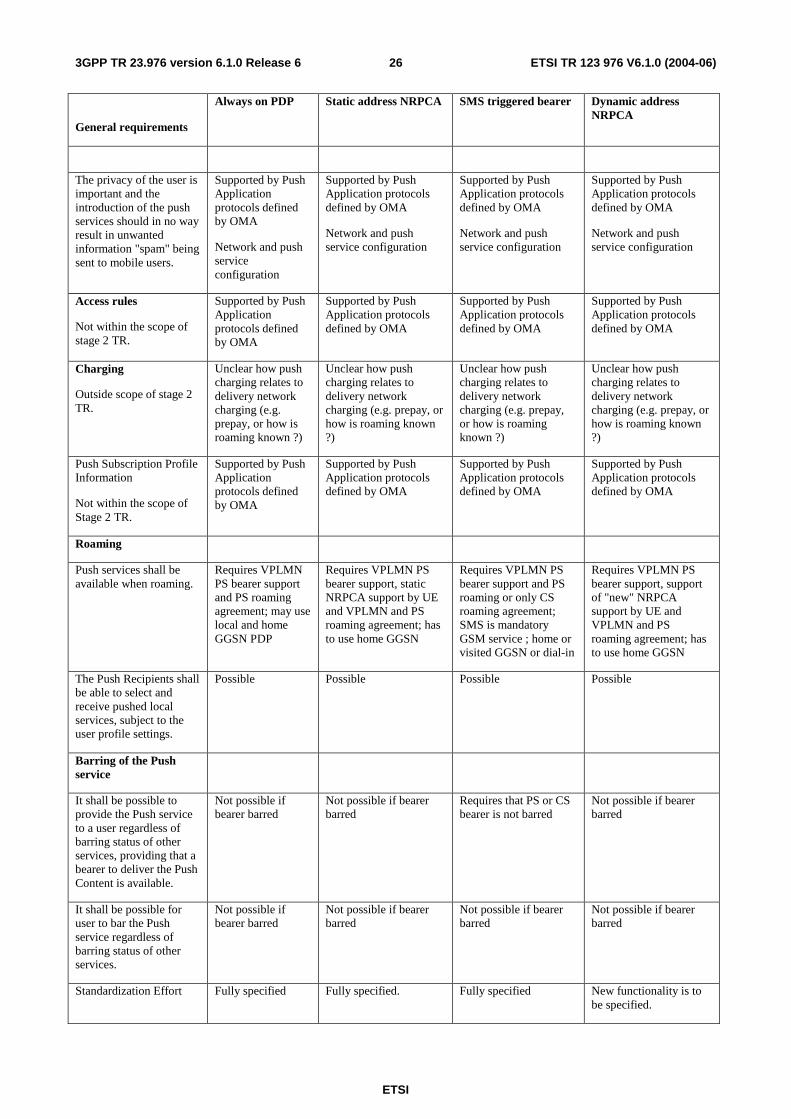
The privacy of the user is important and the introduction of the push services should in no way result in unwanted information "spam" being sent to mobile users.
Supported by Push Application protocols defined by OMA
Network and push service configuration
Supported by Push Application protocols defined by OMA
Network and push service configuration
Supported by Push Application protocols defined by OMA
Network and push service configuration
Supported by Push Application protocols defined by OMA
Network and push service configuration
Access rules
Not within the scope of stage 2 TR.
Supported by Push Application protocols defined by OMA
Supported by Push Application protocols defined by OMA
Supported by Push Application protocols defined by OMA
Supported by Push Application protocols defined by OMA
Charging
Outside scope of stage 2 TR.
Unclear how push charging relates to delivery network charging (e.g. prepay, or how is roaming known ?)
Unclear how push charging relates to delivery network charging (e.g. prepay, or how is roaming known ?)
Unclear how push charging relates to delivery network charging (e.g. prepay, or how is roaming known ?)
Unclear how push charging relates to delivery network charging (e.g. prepay, or how is roaming known ?)
Push Subscription Profile Information
Not within the scope of Stage 2 TR.
Supported by Push Application protocols defined by OMA
Supported by Push Application protocols defined by OMA
Supported by Push Application protocols defined by OMA
Supported by Push Application protocols defined by OMA
Roaming
Push services shall be available when roaming.
Requires VPLMN PS bearer support and PS roaming agreement; may use local and home GGSN PDP
Requires VPLMN PS bearer support, static NRPCA support by UE and VPLMN and PS roaming agreement; has to use home GGSN
Requires VPLMN PS bearer support and PS roaming or only CS roaming agreement; SMS is mandatory GSM service ; home or visited GGSN or dial-in
Requires VPLMN PS bearer support, support of "new" NRPCA support by UE and VPLMN and PS roaming agreement; has to use home GGSN
The Push Recipients shall be able to select and receive pushed local services, subject to the user profile settings.
Possible
Possible Possible Possible
Barring of the Push service
It shall be possible to provide the Push service to a user regardless of barring status of other services, providing that a bearer to deliver the Push Content is available.
Not possible if bearer barred
Not possible if bearer barred
Requires that PS or CS bearer is not barred
Not possible if bearer barred
It shall be possible for user to bar the Push service regardless of barring status of other services.
Not possible if bearer barred
Not possible if bearer barred
Not possible if bearer barred
Not possible if bearer barred
Standardization Effort Fully specified Fully specified. Fully specified New functionality is to be specified.
ETSI
ETSI TR 123 976 V6.1.0 (2004-06) 273GPP TR 23.976 version 6.1.0 Release 6
Comparing NRPCA to long-lived PDP contexts, the resource/performance effort moves from PDP context capacity to higher signalling traffic for PDP contexts establishment and release, i.e. NRPCA allows better usage of the GGSNs PDP Contexts capacity. There is no difference for the user data throughput capacity between approaches. The increase in signaling traffic for NRPCA impacts the performance requirements for the GGSN, SGSN, HLR, and in the case of NRPCA with dynamic IP address assignment the "new entity" (Address Resolver or Presence Server).
For all approaches, except for SMS over CS, the UE has to be PS attached at the SGSN and this requires continuous mobility management procedures, i.e. routeing area updating.
Compared with the other mechanisms NRPCA with dynamic IP addressing introduces new PLMN signalling. Large scale usage of that mechanism requires considerable performance upgrades for "new entity" i.e. Address Resolver (DNS) or Presence Server and additional HLR, GGSN and SGSN signaling performance. NRPCA with dynamic IP addressing moves resource usage from static PDP context to new static contexts on DNS or Presence Server and increases signaling between a number of network entities. NRPCA partly avoids potential delays compared to SMS when delivering the PDP Context activation request. The SMS trigger mechanism may, depending on delivery time requirements, require performance upgrades for SMSC, HLR and SGSN when used in large scale. But the performance may be shared with other SMS applications.
NRPCA with dynamic IP address assignment requires new UE and new network functions. The other approaches, except NRPCA with static IP addressing, are already supported by all or many networks. The NRPCA roaming support depends on new, features supported by the visited network.
The long-lived PDP Context does not require any mechanism to trigger PS based applications when the UE behaviour is to initiate PS connectivity, i.e. to activate a PDP Context. These PS based applications with this type of always-on behaviour will retain PS connectivity during the period of time the application wants to be available for Push services. Existing GPRS procedures (from Release 97) provide sufficient support for PS based applications with this always-on behaviour.
6.2 Conclusion This TR has studied the mechanisms available to allow data to be pushed to a mobile device. The architecture used for Push services includes a Push Function and a Push Initiator. The Push Function acts as a gateway to mobile devices for data pushed from Push Initiators. The mobile device user subscribes to a push service via the Push Function and Push Initiator.
When a mobile device has an active connection, either circuit-switched or packet-switched, data may be pushed to the device based on the subscription to push services agreed between the mobile user and the Push Function and Push Initiator.
If a mobile device has a statically assigned IP address and is attached to the network, the method described for NRPCA with static IP address assignment may be used by the Push Function to initiate a PDP Context with the mobile. It was concluded that NRPCA with dynamic IP address assignment would not be standardised to support Push Services.
When a mobile device is attached to a network but does not have an active PDP Context, it may be possible to send the Push Data using SMS, or to send a notification of pending Push Data using the SMS. SMS may also be used to send a notification to the UE to activate a PDP Context.
It has been determined during this study that at least one of the mechanisms defined in clause 5.1.4 is required to allow the Push Function to learn the status of an active PDP Context, and in particular, when an active PDP Context is deactivated by the network.
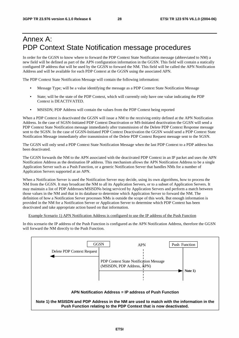
ETSI
ETSI TR 123 976 V6.1.0 (2004-06) 283GPP TR 23.976 version 6.1.0 Release 6
Annex A: PDP Context State Notification message procedures In order for the GGSN to know where to forward the PDP Context State Notification message (abbreviated to NM) a new field will be defined as part of the APN configuration information in the GGSN. This field will contain a statically configured IP address that will be used by the GGSN to forward the NM. This field will be called the APN Notification Address and will be available for each PDP Context at the GGSN using the associated APN.
The PDP Context State Notification Message will contain the following information:
• Message Type; will be a value identifying the message as a PDP Context State Notification Message
• State; will be the state of the PDP Context, which will currently only have one value indicating the PDP Context is DEACTIVATED.
• MSISDN; PDP Address will contain the values from the PDP Context being reported
When a PDP Context is deactivated the GGSN will issue a NM to the receiving entity defined at the APN Notification Address. In the case of SGSN-Initiated PDP Context Deactivation or MS-Initiated deactivation the GGSN will send a PDP Context State Notification message immediately after transmission of the Delete PDP Context Response message sent to the SGSN. In the case of GGSN-Initiated PDP Context Deactivation the GGSN would send a PDP Context State Notification Message immediately after transmission of the Delete PDP Context Request message sent to the SGSN.
The GGSN will only send a PDP Context State Notification Message when the last PDP Context to a PDP address has been deactivated.
The GGSN forwards the NM to the APN associated with the deactivated PDP Context in an IP packet and uses the APN Notification Address as the destination IP address. This mechanism allows the APN Notification Address to be a single Application Server such as a Push Function, or a generic Notification Server that handles NMs for a number of Application Servers supported at an APN.
When a Notification Server is used the Notification Server may decide, using its own algorithms, how to process the NM from the GGSN. It may broadcast the NM to all its Application Servers, or to a subset of Application Servers. It may maintain a list of PDP Addresses/MSISDNs being serviced by Application Servers and perform a match between those values in the NM and that in its database to determine which Application Server to forward the NM. The definition of how a Notification Server processes NMs is outside the scope of this work. But enough information is provided in the NM for a Notification Server or Application Server to determine which PDP Context has been deactivated and take appropriate action based on that information.
Example Scenario 1) APN Notification Address is configured to use the IP address of the Push Function
In this scenario the IP address of the Push Function is configured as the APN Notification Address, therefore the GGSN will forward the NM directly to the Push Function.
GGSN
PDP Context State Notification Message (MSISDN, PDP Address, APN)
Delete PDP Context Request
Push Function APN
Note 1)
APN Notification Address = IP address of Push Function
Note 1) the MSISDN and PDP Address in the NM are used to match with the information in the Push Function relating to the PDP Context that is now deactivated.
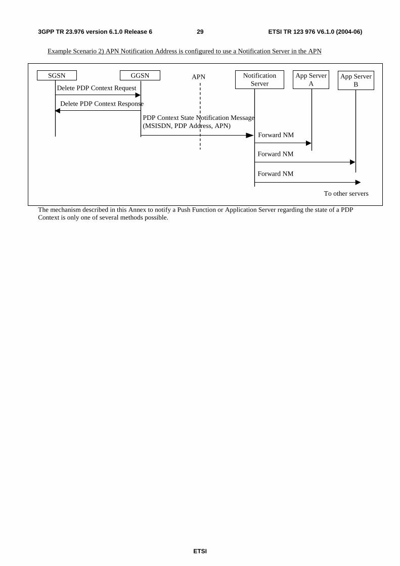
ETSI
ETSI TR 123 976 V6.1.0 (2004-06) 293GPP TR 23.976 version 6.1.0 Release 6
Example Scenario 2) APN Notification Address is configured to use a Notification Server in the APN
The mechanism described in this Annex to notify a Push Function or Application Server regarding the state of a PDP Context is only one of several methods possible.
GGSN
PDP Context State Notification Message (MSISDN, PDP Address, APN)
Delete PDP Context Request
Notification Server
APN App Server A
App Server B
Forward NM
Forward NM
Forward NM
To other servers
SGSN
Delete PDP Context Response
ETSI
ETSI TR 123 976 V6.1.0 (2004-06) 303GPP TR 23.976 version 6.1.0 Release 6
Annex B: NRPCA with no restrictions on APN and GPRS configuration The solution for NRPCA differs from the solution in clause 5.1.5.1 in the following ways:
• There is no restriction on the number of GGSNs that can serve an APN. Therefore the proposal addresses how a NRPCA can begin at one GGSN and then the PDP Context can be Activated at another GGSN.
• In step 9 the SGSN must retain a copy of the GGSN Address for Control Plane that is received in step 4 PDU Notification Request (the home GGSN address), as well as the more recent value for the GGSN Address for Control Plane received from the GGSN' (the GGSN selected by the SGSN), unless the GGSN' is the same as the home GGSN.
• In step 11 the SGSN must use the GGSN Address for Control Plane of the home GGSN to send an Update Address Resolver message to the home GGSN (and subsequently the home AR).
Specific
PDN
Internet Packet
Domain
UE
Gi
Operator Push Function
(PF)
Address Resolver
Network
Push Initiator
(PI) GGSN
Push data flow
HLR
Gc
Figure B1: Architecture for NRPCA with dynamic IP addressing supporting Push
Assumptions
The Address Resolver is implemented using DNS and the User-ID is a unique name in the format user@realm and therefore any query to any Address Resolver in the network will always end up at the home AR for the User-ID.
Notes/Limitations
This proposal requires three changes to the SGSN. In step 4 the PDU Notification Request will contain a null PDP Address. The SGSN must be modified to accept this field as null and forward the Request PDP Context Activation message to the UE with a null PDP Address field. The UE upon receiving a Request PDP Context Activation with a null PDP Address field will use this as an indicator to establish a PDP Context back to the APN contained in the Request PDP Context Activation.
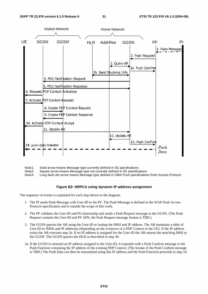
ETSI
ETSI TR 123 976 V6.1.0 (2004-06) 313GPP TR 23.976 version 6.1.0 Release 6
Visited Network Home Network
13. Push Confirm 14. push data transfer
Push
Data
GGSN AddrRes
2. Push Request
3b. Send Routeing Info
12. Update AR
HLR
3. Query AR
PF
3a. Push Confirm
PI
5. PDU Notification Response
4. PDU Notification Request
1. Push-Message
6. Request PDP Context Activation
7. Activate PDP Context Request
8. Create PDP Context Request
9. Create PDP Context Response
10. Activate PDP Context Accept
11. Update AR
UE SGSN GGSN’
Note1: Solid arrow means Message type currently defined in 3G specifications Note2: Square arrow means Message type not currently defined in 3G specifications Note3: Long dash dot arrow means Message type defined in OMA Push specifications Push Access Protocol
Figure B2: NRPCA using dynamic IP address assignment
The sequence of events is explained for each step shown in the diagram.
1. The PI sends Push-Message with User-ID to the PF. The Push-Message is defined in the WAP Push Access Protocol specification and is outside the scope of this work.
2. The PF validates the User-ID and PI relationship and sends a Push Request message to the GGSN. (The Push Request contains the User-ID and PF APN, the Push Request message format is TBD.)
3. The GGSN queries the AR using the User-ID to lookup the IMSI and IP address. The AR maintains a table of User-ID to IMSIs and IP addresses (depending on the existence of a PDP Context to the UE). If the IP address exists the AR executes step 3a. If no IP address is assigned for the User-ID the AR returns the matching IMSI to the GGSN. The GGSN queries the HLR as described in step 3b.
3a. If the GGSN is returned an IP address assigned to the User-ID, it responds with a Push Confirm message to the Push Function containing the IP address of the existing PDP Context. (The format of the Push Confirm message is TBD.) The Push Data can then be transmitted using this IP address and the Push Function proceeds to step 14.
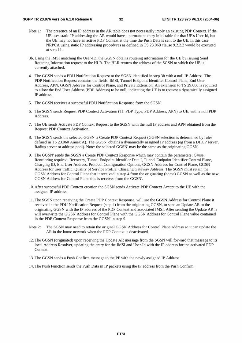
ETSI
ETSI TR 123 976 V6.1.0 (2004-06) 323GPP TR 23.976 version 6.1.0 Release 6
Note 1: The presence of an IP address in the AR table does not necessarily imply an existing PDP Context. If the UE uses static IP addressing the AR would have a permanent entry in its table for that UE's User-Id, but the UE may not have an active PDP Context at the time the Push Data is sent to the UE. In this case NRPCA using static IP addressing procedures as defined in TS 23.060 clause 9.2.2.2 would be executed at step 11.
3b. Using the IMSI matching the User-ID, the GGSN obtains routeing information for the UE by issuing Send Routeing Information request to the HLR. The HLR returns the address of the SGSN to which the UE is currently attached.
4. The GGSN sends a PDU Notification Request to the SGSN identified in step 3b with a null IP Address. The PDP Notification Request contains the fields; IMSI, Tunnel Endpoint Identifier Control Plane, End User Address, APN, GGSN Address for Control Plane, and Private Extension. An extension to TS 29.060 is required to allow the End User Address (PDP Address) to be null, indicating the UE is to request a dynamically assigned IP address.
5. The GGSN receives a successful PDU Notification Response from the SGSN.
6. The SGSN sends Request PDP Context Activation (TI, PDP Type, PDP Address, APN) to UE, with a null PDP Address.
7. The UE sends Activate PDP Context Request to the SGSN with the null IP address and APN obtained from the Request PDP Context Activation.
8. The SGSN sends the selected GGSN' a Create PDP Context Request (GGSN selection is determined by rules defined in TS 23.060 Annex A). The GGSN' obtains a dynamically assigned IP address (eg from a DHCP server, Radius server or address pool). Note: the selected GGSN' may be the same as the originating GGSN.
9. The GGSN' sends the SGSN a Create PDP Context Response which may contain the parameters; Cause, Reordering required, Recovery, Tunnel Endpoint Identifier Data I, Tunnel Endpoint Identifier Control Plane, Charging ID, End User Address, Protocol Configuration Options, GGSN Address for Control Plane, GGSN Address for user traffic, Quality of Service Profile, Charging Gateway Address. The SGSN must retain the GGSN Address for Control Plane that it received in step 4 from the originating (home) GGSN as well as the new GGSN Address for Control Plane this is receives from the GGSN'.
10. After successful PDP Context creation the SGSN sends Activate PDP Context Accept to the UE with the assigned IP address.
11. The SGSN upon receiving the Create PDP Context Response, will use the GGSN Address for Control Plane it received in the PDU Notification Request (step 4) from the originating GGSN, to send an Update AR to the originating GGSN with the IP address of the PDP Context and associated IMSI. After sending the Update AR is will overwrite the GGSN Address for Control Plane with the GGSN Address for Control Plane value contained in the PDP Context Response from the GGSN' in step 9.
Note 2: The SGSN may need to retain the original GGSN Address for Control Plane address so it can update the AR in the home network when the PDP Context is deactivated.
12. The GGSN (originated) upon receiving the Update AR message from the SGSN will forward that message to its local Address Resolver, updating the entry for the IMSI and User-Id with the IP address for the activated PDP Context.
13. The GGSN sends a Push Confirm message to the PF with the newly assigned IP Address.
14. The Push Function sends the Push Data in IP packets using the IP address from the Push Confirm.
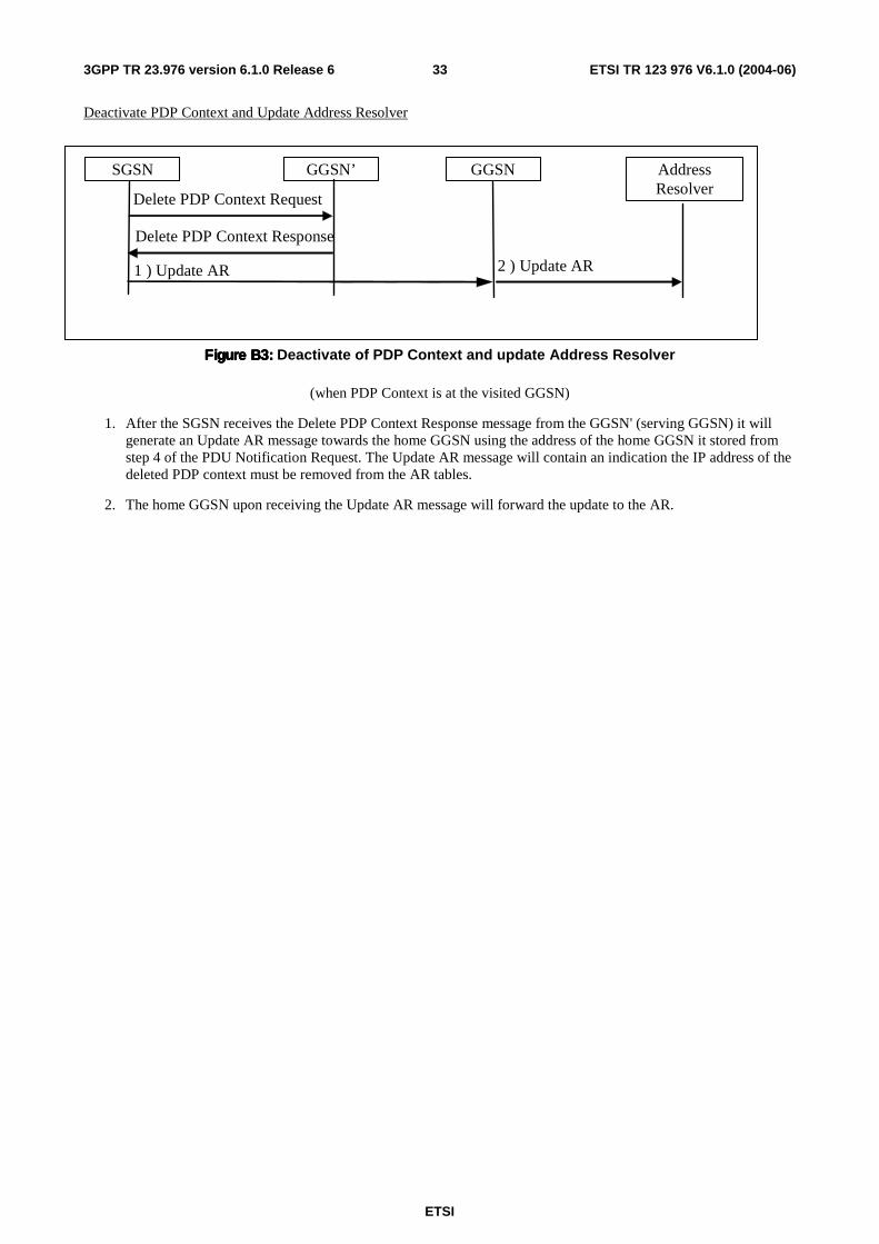
ETSI
ETSI TR 123 976 V6.1.0 (2004-06) 333GPP TR 23.976 version 6.1.0 Release 6
Deactivate PDP Context and Update Address Resolver
Figure B3:Figure B3:Figure B3:Figure B3: Deactivate of PDP Context and update Address Resolver
(when PDP Context is at the visited GGSN)
1. After the SGSN receives the Delete PDP Context Response message from the GGSN' (serving GGSN) it will generate an Update AR message towards the home GGSN using the address of the home GGSN it stored from step 4 of the PDU Notification Request. The Update AR message will contain an indication the IP address of the deleted PDP context must be removed from the AR tables.
2. The home GGSN upon receiving the Update AR message will forward the update to the AR.
GGSN’
1 ) Update AR
Delete PDP Context Request
Address Resolver
SGSN
Delete PDP Context Response
GGSN
2 ) Update AR
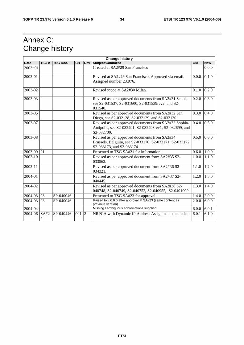
ETSI
ETSI TR 123 976 V6.1.0 (2004-06) 343GPP TR 23.976 version 6.1.0 Release 6
Annex C: Change history
Change history Date TSG # TSG Doc. CR Rev Subject/Comment Old New
2003−01 Created at SA2#29 San Francisco 0.0.0
2003-01 Revised at SA2#29 San Francisco. Approved via email. Assigned number 23.976.
0.0.0 0.1.0
2003-02 Revised scope at SA2#30 Milan. 0.1.0 0.2.0
2003-03 Revised as per approved documents from SA2#31 Seoul, see S2-031537, S2-031600, S2-031539rev2, and S2-031540.
0.2.0 0.3.0
2003-05 Revised as per approved documents from SA2#32 San Diego, see S2-032128, S2-032129, and S2-032130.
0.3.0 0.4.0
2003-07 Revised as per approved documents from SA2#33 Sophia-Antipolis, see S2-032491, S2-032493rev1, S2-032699, and S2-032700.
0.4.0 0.5.0
2003-08 Revised as per approved documents from SA2#34 Brussels, Belgium, see S2-033170, S2-033171, S2-033172, S2-033173, and S2-033174.
0.5.0 0.6.0
2003-09 21 Presented to TSG SA#21 for information. 0.6.0 1.0.0 2003-10 Revised as per approved document from SA2#35 S2-
033562. 1.0.0 1.1.0
2003-11 Revised as per approved document from SA2#36 S2-034321.
1.1.0 1.2.0
2004-01 Revised as per approved document from SA2#37 S2-040445.
1.2.0 1.3.0
2004-02 Revised as per approved documents from SA2#38 S2-040748, S2-040749, S2-040752, S2-040955, S2-0401009
1.3.0 1.4.0
2004-03 23 SP-040046 Presented to TSG SA#23 for approval. 1.4.0 2.0.0 2004-03 23 SP-040046 Raised to v.6.0.0 after approval at SA#23 (same content as
previous version) 2.0.0 6.0.0
2004-04 Missing / ambiguous abbreviations supplied 6.0.0 6.0.1 2004-06 SA#2
4 SP-040446 001 2 NRPCA with Dynamic IP Address Assignment conclusion 6.0.1 6.1.0

ETSI
ETSI TR 123 976 V6.1.0 (2004-06) 353GPP TR 23.976 version 6.1.0 Release 6
History
Document history
V6.1.0 June 2004 Publication