Embed Size (px)
Citation preview
3GPP TS 25.402 V8.1.0 (2009-06) Technical Specification
3rd Generation Partnership Project; Technical Specification Group Radio Access Network;
Synchronisation in UTRAN Stage 2 (Release 8)
The present document has been developed within the 3rd Generation Partnership Project (3GPP TM) and may be further elaborated for the purposes of 3GPP. The present document has not been subject to any approval process by the 3GPP Organisational Partners and shall not be implemented. This Specification is provided for future development work within 3GPP only. The Organisational Partners accept no liability for any use of this Specification. Specifications and reports for implementation of the 3GPP TM system should be obtained via the 3GPP Organisational Partners' Publications Offices.
3GPP
2 Release 8 3GPP TS 25.402 V8.1.0 (2009-06)
Keywords UMTS, radio, stage 2, synchronization
3GPP
Postal address
3GPP support office address 650 Route des Lucioles - Sophia Antipolis
Valbonne - FRANCE Tel.: +33 4 92 94 42 00 Fax: +33 4 93 65 47 16
Internet http://www.3gpp.org
Copyright Notification
No part may be reproduced except as authorized by written permission. The copyright and the foregoing restriction extend to reproduction in all media.
© 2008, 3GPP Organizational Partners (ARIB, ATIS, CCSA, ETSI, TTA, TTC).
All rights reserved.
UMTS™ is a Trade Mark of ETSI registered for the benefit of its members 3GPP™ is a Trade Mark of ETSI registered for the benefit of its Members and of the 3GPP Organizational Partners LTE™ is a Trade Mark of ETSI currently being registered for the benefit of its Members and of the 3GPP Organizational Partners GSM® and the GSM logo are registered and owned by the GSM Association
3GPP
3 Release 8 3GPP TS 25.402 V8.1.0 (2009-06)
Contents Foreword ......................................................................................................................................................5 1 Scope..................................................................................................................................................6 2 References ..........................................................................................................................................6 3 Definitions, symbols and abbreviations ...............................................................................................7 3.1 Definitions...................................................................................................................................................7 3.2 Symbols.......................................................................................................................................................7 3.3 Abbreviations...............................................................................................................................................7 3.4 Specification Notations ................................................................................................................................8 4 Synchronisation Issues ........................................................................................................................9 4.1 General ........................................................................................................................................................9 4.2 Network Synchronisation ...........................................................................................................................11 4.3 Node Synchronisation ................................................................................................................................11 4.4 Transport Channel Synchronisation ............................................................................................................11 4.5 Radio Interface Synchronisation .................................................................................................................11 4.6 Time Alignment Handling..........................................................................................................................12 4.7 Uplink Synchronisation..............................................................................................................................12 5 Synchronisation Counters and Parameters .........................................................................................12 6 Node Synchronisation .......................................................................................................................16 6.1 General ......................................................................................................................................................16 6.1.1 RNC-Node B Node Synchronisation .....................................................................................................16 6.1.2 Inter Node B Node Synchronisation ......................................................................................................18 6.1.2.1 TDD Node B Synchronisation Ports.................................................................................................18 6.1.2.2 TDD Inter Node B Node Synchronisation procedure [3.84Mcps TDD].............................................21 6.1.2.2.1 Preliminary Phase ......................................................................................................................21 6.1.2.2.1A Frequency Acquisition Phase......................................................................................................22 6.1.2.2.1B Initial Phase ...............................................................................................................................22 6.1.2.2.2 Steady-State Phase .....................................................................................................................23 6.1.2.2.3 Late-Entrant Cells ......................................................................................................................23 6.1.2.3 TDD Inter Node B Node Synchronisation procedure [1.28Mcps TDD].............................................23 6.1.2.3.1 Preliminary Phase ......................................................................................................................24 6.1.2.3.2 Initial Phase ...............................................................................................................................24 6.1.2.3.3 Steady-State Phase .....................................................................................................................25 6.1.2.3.3.1 Basic method........................................................................................................................25 6.1.2.3.3.2 Extended method..................................................................................................................25 6.1.2.3.4 Late-Entrant Cells ......................................................................................................................26 6.1.2.4 Node B synchronisation for 3.84Mcps TDD MBSFN IMB...............................................................27 7 Transport Channel Synchronisation...................................................................................................27 7.1 General ......................................................................................................................................................27 7.2 Timing adjustment and Time of Arrival monitoring on Iub/Iur interfaces ....................................................28 8 Radio Interface Synchronisation........................................................................................................31 8.1 General ......................................................................................................................................................31 8.2 FDD Radio Interface Synchronisation ........................................................................................................31 8.2.1 General.................................................................................................................................................31 8.2.2 Neighbour cell list timing information...................................................................................................33 8.3 TDD Radio Interface Synchronisation ........................................................................................................33 8.3.1 General.................................................................................................................................................33 8.3.2 Intercell Synchronisation ......................................................................................................................33 8.3.3 Multi Frame Synchronisation ................................................................................................................34 8.3.4 Timing Advance for 3.84Mcps and 7.68Mcps TDD...............................................................................34 8.3.4.1 Measurement of the timing deviation on the physical channels .........................................................35 8.3.4.2 Assignment of correct timing advance value when establishing new channels...................................35 8.3.4.2.1 Transition to CELL_DCH State..................................................................................................35
3GPP
4 Release 8 3GPP TS 25.402 V8.1.0 (2009-06)
8.3.4.2.2 When establishing an USCH in CELL_FACH state ....................................................................35 8.3.4.2.3 When establishing E-DCH in CELL_DCH state (E-DCH/HS-DSCH operation with no UL
DPCH).......................................................................................................................................36 8.3.4.3 Update of timing advance value for channels in operation ................................................................36 8.3.4.3.1 UE in CELL_DCH state.............................................................................................................36 8.3.4.3.2 UE with USCH Traffic in CELL_FACH state ............................................................................36 8.3.4.4 Setting of timing advance value for target cell at handover ...............................................................37 8.3.4.4.1 General......................................................................................................................................37 8.3.4.4.2 Handover from TDD to TDD with synchronised cells.................................................................37 8.3.4.4.3 Handover from FDD to TDD, Handover from other systems to TDD, or Handover from TDD
to TDD with unsynchronised cells..............................................................................................37 8.3.5 UL Synchronisation for 1.28Mcps TDD................................................................................................37 8.3.5.1 The establishment of uplink synchronisation ...................................................................................37 8.3.5.1.1 Preparation of uplink synchronisation by downlink synchronisation............................................37 8.3.5.1.2 Establishment of uplink synchronisation.....................................................................................37 8.3.5.2. Maintenance of uplink synchronisation ............................................................................................38 9 Usage of Synchronisation Counters and Parameters to support Transport Channel and Radio
Interface Synchronisation..................................................................................................................38 9.1 General ......................................................................................................................................................38 9.2 Calculations performed in the UTRAN.......................................................................................................41 9.2.1 UE in CELL_FACH/PCH state .............................................................................................................41 9.2.2 UE changes from CELL_FACH/PCH state to CELL_DCH state: 1 RL..................................................41 9.2.3 [FDD - UE changes from CELL_FACH/PCH state to CELL_DCH state: several RL's] .........................41 9.2.4 UE in CELL_DCH state: addition of a new RL or handover to a new cell ..............................................41 9.2.5 Handover from other RAN to UMTS ....................................................................................................42 9.3 Calculations performed in the UE...............................................................................................................42 9.3.A UE in CELL_FACH/PCH state .............................................................................................................42 9.3.1 UE changes from CELL_FACH/PCH state to CELL_DCH state: 1 RL..................................................42 9.3.1A [FDD - UE changes from CELL_FACH/PCH to CELL_DCH state: several RL's] .................................42 9.3.2 UE in CELL_DCH state: addition of a new RL or handover to a new cell ..............................................42 9.4 Synchronisation of L1 configuration changes..............................................................................................43 9.5 Examples of synchronisation counters during state transitions.....................................................................43 10 Time Alignment Handling.................................................................................................................47 11 MBMS related Transport Channel Synchronisation ...........................................................................48 11.1 General ......................................................................................................................................................48 11.2 FDD MBMS related Transport Channel Synchronisation ............................................................................48 11.3 TDD MBMS related Transport Channel Synchronisation............................................................................49 11.4 Inter-Node B Synchronisation of MTCH Transmissions for IP Multicast.....................................................49 11.5 3.84Mcps TDD MBSFN IMB Transport Channel Synchronisation..............................................................50
Annex A (informative): Change history ...........................................................................................51
3GPP
5 Release 8 3GPP TS 25.402 V8.1.0 (2009-06)
Foreword This Technical Specification (TS) has been produced by the 3rd Generation Partnership Project (3GPP).
The contents of the present document are subject to continuing work within the TSG and may change following formal TSG approval. Should the TSG modify the contents of the present document, it will be re-released by the TSG with an identifying change of release date and an increase in version number as follows:
Version x.y.z
where:
x the first digit:
1 presented to TSG for information;
2 presented to TSG for approval;
3 or greater indicates TSG approved document under change control.
y the second digit is incremented for all changes of substance, i.e. technical enhancements, corrections, updates, etc.
z the third digit is incremented when editorial only changes have been incorporated in the document.
3GPP
6 Release 8 3GPP TS 25.402 V8.1.0 (2009-06)
1 Scope The present document constitutes the stage 2 specification of different synchronisation mechanisms in UTRAN and on Uu.
2 References The following documents contain provisions which, through reference in this text, constitute provisions of the present document.
References are either specific (identified by date of publication, edition number, version number, etc.) or non-specific.
For a specific reference, subsequent revisions do not apply.
For a non-specific reference, the latest version applies. In the case of a reference to a 3GPP document (including a GSM document), a non-specific reference implicitly refers to the latest version of that document in the same Release as the present document.
[1] 3GPP TS 25.401: "UTRAN Overall Description".
[2] 3GPP TS 25.423: "UTRAN Iur Interface RNSAP Signalling".
[3] 3GPP TS 25.433: "UTRAN Iub Interface NBAP Signalling".
[4] 3GPP TS 25.435: "UTRAN Iub Interface User Plane Protocols for COMMON TRANSPORT CHANNEL Data Streams".
[5] 3GPP TS 25.427: "Iub/Iur Interface User Plane Protocol for DCH Data Streams".
[6] TIA/EIA 422 B: "Electrical characteristics of balanced voltage digital interface circuits".
[7] 3GPP TS 25.411: "UTRAN Iu Interface Layer 1".
[8] 3GPP TS 25.421: "UTRAN Iur Interface Layer 1".
[9] 3GPP TS 25.431: "UTRAN Iub Interface Layer 1".
[10] 3GPP TS 25.104: "UTRA (BS) FDD; Radio transmission and Reception".
[11] 3GPP TS 25.211: "Physical channels and mapping of transport channels onto physical channels (FDD)".
[12] 3GPP TS 25.223: "Spreading and modulation (TDD)".
[13] 3GPP TS 25.215: "Physical layer - Measurements (FDD)".
[14] 3GPP TS 25.225: "Physical layer - Measurements (TDD)".
[15] 3GPP TS 25.123: "Requirements for Support of Radio Resource Management (TDD)".
[16] 3GPP TS 25.224: "Physical Layer Procedures (TDD)".
[17] 3GPP TS 25.105: "UTRA (BS) TDD, Radio transmission and Reception".
[18] ITU-T Recommendation G.811 (09/1997): "Timing Characteristics of Primary Reference Clocks".
[19] ITU-T Recommendation G.812 (06/1998): "Timing Requirements of Slave Clocks suitable for use as Node Clocks in Synchronization Network".
[20] ITU-T Recommendation G.813 (08/1996): "Timing Characteristics of SDH equipment slave clocks (SEC)".
3GPP
7 Release 8 3GPP TS 25.402 V8.1.0 (2009-06)
[21] ETSI EN 300 462-4-1(03/1998): "Transmission and Multiplexing (TM); Generic requirements for synchronization networks; Part 4-1: Timing characteristics of slave clocks suitable for synchronization supply to Synchronous Digital Hierarchy (SDH) and Plesiochronous Digital Hierarchy (PDH) equipment".
[22] ETSI EN 300 462-5-1 (09/1996):"Transmission and Multiplexing (TM); Generic requirements for synchronization networks; Part 5-1: Timing characteristics of slave clocks suitable for operation in Synchronous Digital Hierarchy (SDH) equipment".
[23] ETSI EN 300 462-7-1 (04/2001): "Transmission and Multiplexing (TM); Generic requirements for synchronization networks; Part 7-1: Timing characteristics of slave clocks suitable for synchronisation supply to equipment in local node applications".
[24] 3GPP TS 25.212: "Multiplexing and channel coding (FDD)".
[25] 3GPP TS 25.222: "Multiplexing and channel coding (TDD)".
[26] 3GPP TS 25.321: "Medium Access Control (MAC) protocol specification".
3 Definitions, symbols and abbreviations
3.1 Definitions Network Synchronisation: generic concept that depicts the way of distributing a common frequency to all elements in a network
Reference Timing Signal: timing signal of specified performance that can be used as a timing source for a slave clock
Holdover mode: operating condition of a clock which has lost its controlling reference input and is using stored data, acquired while in locked operation (that is while controlled by an external input reference), to control its output. The stored data are used to control phase and frequency variations, allowing the locked condition to be reproduced within specifications.
3.2 Symbols No special symbols are defined in this document.
3.3 Abbreviations For the purposes of the present document, the following abbreviations apply:
ACK (time alignment) acknowledgement BFN Node B Frame Number (counter) CFN Connection Frame Number (counter) CH Channel CN Core Network CPICH Common Pilot Channel CRNC Controlling RNC DL Down Link DCH Dedicated Channel DOFFFDD FDD Default DPCH Offset value DOFFTDD TDD Default DPCH Offset value DPCH Dedicated Physical Channel DPCCH Dedicated Physical Control Channel DRNC Drift RNC DSCH Downlink Shared Channel FACH Forward Access Channel FDD Frequency Division Duplex F-DPCH Fractional DPCH
3GPP
8 Release 8 3GPP TS 25.402 V8.1.0 (2009-06)
GPS Global Positioning System HO Handover IMB Integrated Mobile Broadcast LTOA Latest Time of Arrival L1 Layer 1 L2 Layer 2 MAC Medium Access Control MBMS Multimedia Broadcast Multicast Service MBSFN Multicast/Broadcast over a Single Frequency Network MCCH MBMS point-to-multipoint Control Channel MFN Multicast Frame Number (counter) MTCH MBMS point-to-multipoint Traffic Channel NACK (time alignment) negative acknowledgement PCCPCH Primary Common Control Physical Channel PCH Paging Channel PDU Packet Data Unit PTP Point-to-Point PTM Point-to-Multipoint PUSCH Physical Uplink Shared Channel RAB Radio Access Bearer RACH Random Access Channel RAN Radio Access Network RFN RNC Frame Number (counter) RL Radio Link RNC Radio Network Controller RNS Radio Network Subsystem RRC Radio Resource Control SAP Service Access Point SCH Synchronisation Channel SFN Cell System Frame Number (counter) SRNC Serving RNC SRNS Serving RNS TBS Transport Block Set TDD Time Division Duplex TOA Time Of Arrival TOAWE Time Of Arrival Window Endpoint TOAWS Time Of Arrival Window Startpoint TTI Time Transmission Interval UE User Equipment UL Up Link UMTS Universal Mobile Telecommunications System USCH Uplink Shared CHannel UTRAN UMTS Terrestrial Radio Access Network
3.4 Specification Notations For the purposes of the present document, the following notations apply:
[FDD] This tagging of a word indicates that the word preceding the tag "[FDD]" applies only to FDD. This tagging of a heading indicates that the heading preceding the tag "[FDD]" and the section following the heading applies only to FDD.
[TDD] This tagging of a word indicates that the word preceding the tag "[TDD]" applies only to TDD,
including 3.84Mcps TDD, 7.68Mcps TDD and 1.28Mcps TDD. This tagging of a heading indicates that the heading preceding the tag "[TDD]" and the section following the heading applies only to TDD, including 3.84Mcps TDD, 7.68Mcps TDD and 1.28Mcps TDD.
[3.84Mcps TDD] This tagging of a word indicates that the word preceding the tag "[3.84Mcps TDD]" applies only
to 3.84Mcps TDD. This tagging of a heading indicates that the heading preceding the tag "[3.84Mcps TDD]" and the section following the heading applies only to 3.84Mcps TDD.
3GPP
9 Release 8 3GPP TS 25.402 V8.1.0 (2009-06)
[1.28Mcps TDD] This tagging of a word indicates that the word preceding the tag "[1.28Mcps TDD]" applies only to 1.28Mcps TDD. This tagging of a heading indicates that the heading preceding the tag "[1.28Mcps TDD]" and the section following the heading applies only to 1.28Mcps TDD.
[7.68Mcps TDD] This tagging of a word indicates that the word preceding the tag "[7.68Mcps TDD]" applies only
to 7.68Mcps TDD. This tagging of a heading indicates that the heading preceding the tag "[7.68Mcps TDD]" and the section following the heading applies only to 7.68Mcps TDD.
[FDD - …] This tagging indicates that the enclosed text following the "[FDD - " applies only to FDD.
Multiple sequential paragraphs applying only to FDD are enclosed separately to enable insertion of TDD specific (or common) paragraphs between the FDD specific paragraphs.
[TDD - …] This tagging indicates that the enclosed text following the "[TDD - " applies only to TDD
including 3.84Mcps TDD, 7.68Mcps TDD and 1.28Mcps TDD. Multiple sequential paragraphs applying only to TDD are enclosed separately to enable insertion of FDD specific (or common) paragraphs between the TDD specific paragraphs.
[3.84Mcps TDD - …] This tagging indicates that the enclosed text following the "[3.84Mcps TDD - " applies only
to 3.84Mcps TDD. Multiple sequential paragraphs applying only to 3.84Mcps TDD are enclosed separately to enable insertion of FDD and TDD specific (or common) paragraphs between the 3.84Mcps TDD specific paragraphs.
[1.28Mcps TDD - …] This tagging indicates that the enclosed text following the "[1.28Mcps TDD - " applies only
to 1.28Mcps TDD. Multiple sequential paragraphs applying only to 1.28Mcps TDD are enclosed separately to enable insertion of FDD and TDD specific (or common) paragraphs between the 1.28Mcps TDD specific paragraphs.
[7.68Mcps TDD - …] This tagging indicates that the enclosed text following the "[7.68Mcps TDD - " applies only
to 7.68Mcps TDD. Multiple sequential paragraphs applying only to 7.68Mcps TDD are enclosed separately to enable insertion of FDD and TDD specific (or common) paragraphs between the 7.68Mcps TDD specific paragraphs.
Procedure When referring to an elementary procedure in the specification, the Procedure Name is written
with the first letters in each word in upper case characters followed by the word "procedure", e.g. Radio Link Setup procedure.
Message When referring to a message in the specification, the MESSAGE NAME is written with all letters
in upper case characters followed by the word "message", e.g. RADIO LINK SETUP REQUEST message.
IE When referring to an information element (IE) in the specification, the Information Element Name
is written with the first letters in each word in upper case characters and all letters in Italic font followed by the abbreviation "IE", e.g. Transport Format Set IE.
Value of an IE When referring to the value of an information element (IE) in the specification, the "Value" is
enclosed by quotation marks, e.g. "Abstract Syntax Error (Reject)". Frame When referring to a control or data frame in the specification, the CONTROL/DATA FRAME
NAME is written with all letters in upper case characters followed by the words "control/data frame", e.g. FACH FLOW CONTROL control frame.
4 Synchronisation Issues
4.1 General This clause identifies the different UTRAN synchronisation issues, i.e.:
- Network Synchronisation;
- Node Synchronization;
3GPP
10 Release 8 3GPP TS 25.402 V8.1.0 (2009-06)
- Transport Channel Synchronisation;
- Radio Interface Synchronisation;
- Time Alignment Handling;
- Uplink Synchronisation.
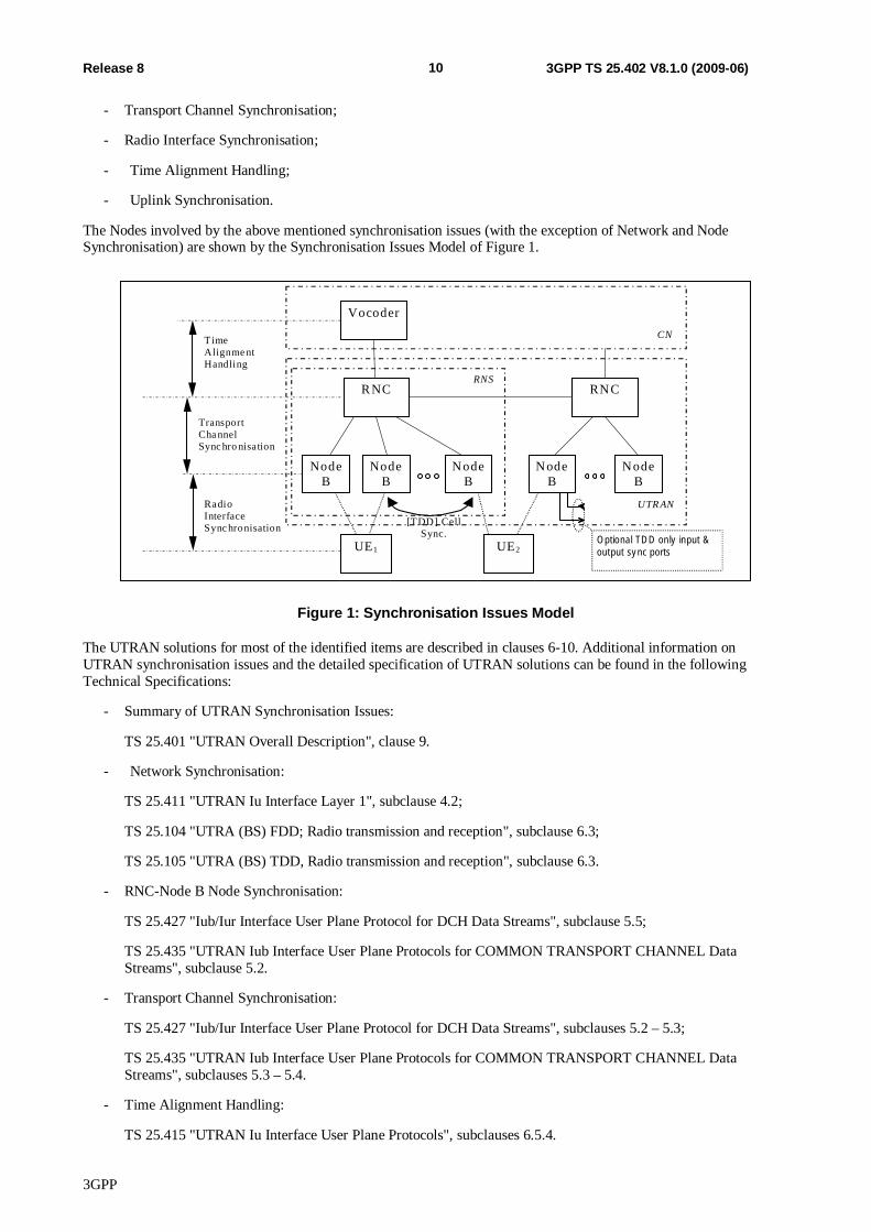
The Nodes involved by the above mentioned synchronisation issues (with the exception of Network and Node Synchronisation) are shown by the Synchronisation Issues Model of Figure 1.
TimeAlignme ntHandling
TransportCha nnelSync hro nisation
RadioInterfaceSync hronisation
NodeB
RNC
Vocoder
NodeB
NodeB
NodeB
NodeB
RNS
UTR AN
CN
UE1 UE2
RNC
Optional TD D only input &output sy nc ports
[TDD] CellSync.
Figure 1: Synchronisation Issues Model
The UTRAN solutions for most of the identified items are described in clauses 6-10. Additional information on UTRAN synchronisation issues and the detailed specification of UTRAN solutions can be found in the following Technical Specifications:
- Summary of UTRAN Synchronisation Issues:
TS 25.401 "UTRAN Overall Description", clause 9.
- Network Synchronisation:
TS 25.411 "UTRAN Iu Interface Layer 1", subclause 4.2;
TS 25.104 "UTRA (BS) FDD; Radio transmission and reception", subclause 6.3;
TS 25.105 "UTRA (BS) TDD, Radio transmission and reception", subclause 6.3.
- RNC-Node B Node Synchronisation:
TS 25.427 "Iub/Iur Interface User Plane Protocol for DCH Data Streams", subclause 5.5;
TS 25.435 "UTRAN Iub Interface User Plane Protocols for COMMON TRANSPORT CHANNEL Data Streams", subclause 5.2.
- Transport Channel Synchronisation:
TS 25.427 "Iub/Iur Interface User Plane Protocol for DCH Data Streams", subclauses 5.2 – 5.3;
TS 25.435 "UTRAN Iub Interface User Plane Protocols for COMMON TRANSPORT CHANNEL Data Streams", subclauses 5.3 – 5.4.
- Time Alignment Handling:
TS 25.415 "UTRAN Iu Interface User Plane Protocols", subclauses 6.5.4.
3GPP
11 Release 8 3GPP TS 25.402 V8.1.0 (2009-06)
4.2 Network Synchronisation Network Synchronisation relates to the distribution of synchronisation references to the UTRAN Nodes and the stability of the clocks in the UTRAN (and performance requirements on UTRAN internal interfaces).
The distribution of an accurate frequency reference to the network elements in the UTRAN is related to several aspects. One main issue is the possibility to provide a synchronisation reference with a frequency accuracy better than 0.05 ppm at the Node B in order to properly generate signals on the radio interface (see references [10] and [17]).
A general recommendation is to supply a traceable synchronisation reference according to reference [18].
The clock to be implemented in UTRAN Nodes shall be chosen with characteristics that depends on the L1 adopted (see reference [8] and [9]) and on the Network Synchronisation strategy adopted. Already standardized clocks may be used (see references [19], [20], [21], [22] and [23]).
For example in order to support STM-N interfaces at the RNC, the ITU-T Recommendation G.813 (see reference [20]) may be sufficient. The implementation in the UTRAN of a better performing clock (in terms of holdover) may be recommended for distribution of a 0.05 ppm during failures in the synchronisation network (EN 300 462-7-1, see reference [23], EN 300 462-4-1, see reference [21], or ITU-T Recommendation G.812 type 1, type 2 or type 3, see reference [19]).
4.3 Node Synchronisation Node Synchronisation relates to the estimation and compensation of timing differences among UTRAN nodes. FDD and TDD modes have different requirements on the accuracy of the timing difference estimation and on the necessity to compensate for these differences.
Two types of Node Synchronisation can be identified, "RNC-Node B" and "Inter Node B" Node Synchronisation. Their usage differs and the requirements differ between the FDD and TDD modes.
"RNC-Node B" Node Synchronisation allows to get knowledge of the timing differences between RNC and its Node Bs.
"Inter Node B" Node Synchronisation may be used in the TDD mode to compensate the timing differences among Node Bs in order to achieve a common timing reference. The purpose of having a common timing reference is to allow Intercell Synchronisation, which is used, within neighbouring cells to minimise cross-interference.
Positioning / Localisation functions may also set requirements on Node Synchronisation.
4.4 Transport Channel Synchronisation The Transport Channel Synchronisation mechanism defines synchronisation of the frame transport between RNC and Node B, considering radio interface timing.
DL TBS transmission is adjusted to fit receiver by adjusting the DL TBS timing in upper node.
4.5 Radio Interface Synchronisation The Radio Interface Synchronisation relates to the timing of the radio frame transmission (either in downlink [FDD] or in both directions [TDD]). FDD and TDD have different mechanisms to determine the exact timing of the radio frame transmission and also different requirements on the accuracy of this timing.
In FDD Radio Interface Synchronisation is necessary to assure that the UE receives radio frames synchronously from different cells, in order to minimise UE buffers.
In TDD Radio Interface Synchronisation refers to the following two aspects:
- Intercell Synchronisation that is used to synchronise radio frames within neighbouring cells in order to minimise cells cross-interference, to allow frame wise hopping mechanisms among cells (e.g. Cell Parameter Cycling according to reference [12]) and to make procedures involving more cells (e.g. handover) easier and more efficient;
3GPP
12 Release 8 3GPP TS 25.402 V8.1.0 (2009-06)
- Timing advance that is used between UE and UTRAN in order to minimise UE-cell interference. In the 1.28 Mcps TDD option, timing advance is provided by uplink synchronisation.
4.6 Time Alignment Handling The Time Alignment Handling procedure over Iu relates to the control of DL transmission timing in the CN nodes in order to minimise the buffer delay in SRNC. This procedure is controlled by SRNC.
4.7 Uplink Synchronisation In 1.28Mpcs TDD Uplink Synchronisation is performed at Layer 1 for PRACH and uplink DPCH. This procedure includes the establishment of UL synchronisation and maintenance of the UL synchronisation.
5 Synchronisation Counters and Parameters This clause defines counters and parameters used in the different UTRAN synchronisation procedures.
BFN Node B Frame Number counter. This is the Node B common frame number counter. [FDD -BFN is optionally frequency-locked to a Network synchronisation reference]. Range: 0 .. 4095 frames.
RFN RNC Frame Number counter. This is the RNC node common frame number counter. RFN is optionally frequency-locked to a Network synchronisation reference. Range: 0 .. 4095 frames.
SFN Cell System Frame Number counter. SFN is sent on BCH. SFN is used for paging groups and system information scheduling etc. In FDD SFN = BFN adjusted with T_cell. In TDD, if Inter Node B synchronisation port is used, SFN is locked to the BFN (i.e. SFN mod 256 = BFN mod 256). Range: 0 .. 4095 frames.
CFN Connection Frame Number (counter). CFN is the frame counter used for the L2/transport channel synchronisation between UE and UTRAN. A CFN value is associated to each TBS and it is passed together with it through the MAC-L1 SAP. CFN provides a common frame reference (at L2) to be used e.g. for synchronised transport channel reconfiguration (see [2] and [3]).
The duration of the CFN cycle is longer than the maximum allowed transport delay between MAC and L1 (in UTRAN side, between SRNC and Node B, because the L1 functions that handle the transport channel synchronisation are in the Node B). Range: 0 .. 255 frames. When used for PCH the range is 0 .. 4095 frames.
Frame Offset Frame Offset is a radio link specific L1 parameter used to map the CFN, used in the transport channel, into the SFN that defines the specific radio frame for the transmission on the air interface.
At the L1/L2 interaction, the mapping is performed as:
- SFN mod 256 = (CFN + Frame Offset) mod 256 (from L2 to L1) (5.1);
- CFN = (SFN - Frame Offset) mod 256 (from L1 to L2) (5.2).
The resolution of all three parameters is 1 frame. Frame Offset and CFN have the same range (0…255) and only the 8 least significant bits of the SFN are used. The operations above are modulo 256.
In the UTRAN, the Frame Offset parameter is calculated by the SRNC and provided to the Node B.
3GPP
13 Release 8 3GPP TS 25.402 V8.1.0 (2009-06)
OFF The parameter OFF is calculated by the UE and reported to the UTRAN only when the UTRAN has requested the UE to send this parameter. In the neighbouring cell list, the UTRAN indicates for each cell if the Frame Offset is already known by the UTRAN or shall be measured and reported by the UE.
OFF has a resolution of 1 frame and a range of 0 .. 255.
Five different cases are discerned related to the determination of the OFF value by the UE:
1. The UE changes from common channel state to dedicated channel state: 1 RL. In this case OFF is zero.
2. [FDD -The UE changes from common channel state to dedicated channel state: several RL's. OFF is in this case defined as being the difference between SFN of the candidate cells and the SFN of the camping cell. Again the UE sets OFF to zero for the cell to which the UE sends an UL RRC message (cell #1). For cells #2 to n, the UE sets OFF to the difference between the SFN of cell#2,n and the SFN of cell#1. This could be seen as if a virtual dedicated physical channel (DPCH) already is aligned with cell #1].
3. The UE adds another RL or moves to another cell in dedicated channel state. OFF is in this case defined as being the time difference between the CFN and the SFN of the cell in which the RL is to be added. In case this difference cannot be measured, a value as in [FDD - 13] [TDD - 14] shall be reported instead.
4. The UE is coming from another RAN and goes to dedicated channel state: 1 RL. This case is identical to case 1).
5. [FDD - The UE is coming from another RAN or another frequency in the same RAN and goes to dedicated channel state: several RL's. This case is identical to case 2], with one exception: OFF will not be zero for the cell to which the UE sends an UL RRC message (the measurement information will be received via the CN in this case) but for a reference cell selected by the UE. All other reported OFF values will be relative to the SFN of this selected reference cell].
[FDD – DOFFFDD] The DOFFFDD (FDD Default DPCH Offset value) is used to define Frame Offset and Chip
Offset at first RL setup. The DOFFFDD is used for both the DPCH and the F-DPCH. The resolution should be good enough to spread out load over Iub and load in Node B (based on certain load distributing algorithms). In addition it is used to spread out the location of Pilot Symbol in order to reduce the peak DL power since Pilot symbol is always transmitting at the fixed location within a slot (the largest number of chips for one symbol is 512 chips).
The SRNC sends a DOFFFDD parameter to the UE when the new RL will make the UE change its state (from Cell_FACH state or other when coming from another RAN) to Cell_DCH state.
Resolution: 512 chips; Range:0 .. 599 (< 80 ms).
[TDD – DOFFTDD] The DOFFTDD (TDD Default DPCH Offset value) is used to define Frame Offset at first RL setup, in order to spread out load over /Iur and load in Node B (based on certain load distributing algorithms).
The SRNC sends a DOFFTDD parameter to the UE when the new RL will make the UE change its state (from Cell_FACH state or other when coming from another RAN) to the Cell_DCH state.
Resolution: 1 frame; Range: 0 .. 7 frames.
3GPP
14 Release 8 3GPP TS 25.402 V8.1.0 (2009-06)
[FDD – Chip Offset] The Chip Offset is used as offset for the DL DPCH or the F-DPCH relative to the PCCPCH timing. The Chip Offset parameter has a resolution of 1 chip and a range of 0 .. 38399 (< 10 ms).
The Chip Offset parameter is calculated by the SRNC and provided to the Node B.
Frame Offset + Chip Offset (sent via NBAP) are in Node B rounded together to closest 256 chip boundary. The 256 chip boundary is used regardless of the used spreading factor, also when the spreading factor is 512. The rounded value (which is calculated in Node B) controls the DL DPCH air-interface timing or the F-DPCH air-interface timing.
The "Frame Offset + Chip Offset" 256 chip boundary rounding rules for Node B to consider for each DL DPCH and each F-DPCH are:
1. IF (Frame Offset x 38 400 + Chip Offset) modulo 256 [chips] = {1..127} THEN round (Frame Offset x 38 400 + Chip Offset) modulo 256 frames down to closest 256 chip boundary.
2. IF (Frame Offset x 38 400 + Chip Offset) modulo 256 [chips] = {128..255} THEN round (Frame Offset x 38 400 + Chip Offset) modulo 256 frames up to closest 256 chip boundary.
3. IF (Frame Offset x 38 400 + Chip Offset) modulo 256 [chips] = 0 THEN "Frame Offset x 38 400 + Chip Offset" is already on a 256 chip boundary.
[FDD – DPCH Frame Offset]
The DPCH Frame Offset is used as offset for the DL DPCH or the F-DPCH relative to the PCCPCH timing at both the Node B and the UE. The DPCH Frame Offset parameter has a resolution of 256 chips and a range of 0 .. 38144 chips (< 10 ms).
The DPCH Frame Offset is equivalent to Chip Offset rounded to the closest 256 chip boundary. It is calculated by the SRNC and sent to the UE by the SRNC for each radio link in the active set.
The DPCH Frame Offset controls the DL DPCH air-interface timing or the F-DPCH air-interface timing. It enables the DL DPCHs or the F-DPCH for radio links in the Active Set to be received at the UE at approximately the same time, which can then be soft combined during soft handover.
[FDD – S-CCPCH Frame Offset]
The S-CCPCH Frame Offset is used as offset for the S-CCPCH relative to the P-CCPCH timing of the same cell at the Node B. It may be applied to S-CCPCHs carrying MTCH. The purpose of S-CCPCH Frame Offset is enabling of soft combining of MBMS data at the UE, in particular for the case of long-lived MBMS sessions.
The S-CCPCH Frame Offset can take the values 0, 10, 20 or 40msecs.
[FDD –Tm] The reported Tm parameter has a resolution of 1 chip and a range of 0 .. 38399. The Tm shall always be sent by the UE.
Five different cases are discerned related to the determination of the Tm value by the UE:
1. The UE changes from common channel state to dedicated channel state: 1 RL. In this case the Tm will be zero.
2. The UE changes from common channel state to dedicated channel state: several RL's. Tm is in this case defined as being the time difference between the received PCCPCH path of the source cell and the received PCCPCH paths of the other target cells. Again the UE sets Tm to zero for the cell to which the UE sends an UL RRC message (cell #1). For cells #2 to n, the UE sets Tm to the time difference of the PCCPCH reception timing of cell#2,n from the PCCPCH reception timing of cell#1.
3GPP
15 Release 8 3GPP TS 25.402 V8.1.0 (2009-06)
3. The UE adds another RL in dedicated channel state (macro-diversity). Tm is in this case defined as being the time difference between "TUETX – To" and the earliest received PCCPCH path of the target cell. TUETX is the time when the UE transmits an uplink DPCCH frame, hence "TUETX – To" is the nominal arrival time for the first path of a received DPCH.
4. The UE is coming from another RAN and goes to dedicated channel state: 1 RL. This case is identical to case 1.
5. The UE is coming from another RAN or another frequency in the same RAN and goes to dedicated channel state: several RL's. This case is identical to case 2, with one exception: Tm will not be zero for the cell to which the UE sends an UL RRC message (the measurement information will be received via the CN in this case) but for a reference cell selected by the UE. All other reported Tm values will be relative to the timing of the PCCPCH in this cell.
[FDD – T_cell] T_cell represents the Timing delay used for defining the start of SCH, CPICH and the DL Scrambling Code(s) in a cell relative BFN. The main purpose is to avoid having overlapping SCHs in different cells belonging to the same Node B. A SCH burst is 256 chips long. SFN in a cell is delayed T_cell relative BFN.
Resolution: 256 chips. Range: 0 .. 9 x 256 chips.
T1 RNC specific frame number (RFN) that indicates the time when RNC sends the DL NODE SYNCHRONISATION control frame through the SAP to the transport layer.
Resolution: 0.125 ms; Range: 0 .. 40959.875 ms.
T2 Node B specific frame number (BFN) that indicates the time when Node B receives the correspondent DL NODE SYNCHRONISATION control frame through the SAP from the transport layer.
Resolution: 0.125 ms; Range: 0 .. 40959.875 ms.
T3 Node B specific frame number (BFN) that indicates the time when Node B sends the UL NODE SYNCHRONISATION control frame through the SAP to the transport layer.
Resolution: 0.125 ms; Range: 0 .. 40959.875 ms.
T4 RNC specific frame number (RFN) that indicates the time when RNC receives the UL NODE SYNCHRONISATION control frame. Used in RNC locally. Not standardised over Iub.
TOAWS TOAWS (Time of Arrival Window Startpoint) is the window startpoint. DL DATA FRAMES are expected to be received after this window startpoint. TOAWS is defined with a positive value relative Time of Arrival Window Endpoint (TOAWE) (see Figure 10). A data frame arriving before TOAWS gives a TIMING ADJUSTMENT control frame response. The resolution is 1 ms, the range is: {0 .. CFN length/2 –1 ms}.
TOAWE TOAWE (Time of Arrival Window Endpoint) is the window endpoint. DL DATA FRAMES are expected to be received before this window endpoint (see Figure 10). TOAWE is defined with a positive value relative Latest Time of Arrival (LTOA). A data frame arriving after TOAWE gives a TIMING ADJUSTMENT control frame response. The resolution is 1 ms, the range is: {0 .. CFN length –1 ms}.
LTOA LTOA (Latest Time of Arrival) is the latest time instant a Node B can receive a data frame and still be able to process it. Data frames received after LTOA can not be processed (discarded). LTOA is defined internally in Node B to be a processing time before the data frame is sent in air-interface. The processing time (Tproc) could be vendor and service dependent. LTOA is the reference for TOAWE (see Figure 14).
3GPP
16 Release 8 3GPP TS 25.402 V8.1.0 (2009-06)
TOA TOA (Time of Arrival) is the time difference between the TOAWE and when a data frame is received. A positive TOA means that data frames are received before TOAWE, a negative TOA means that data frames are received after TOAWE. Data frames that are received after TOAWE but before LTOA are processed by Node B. TOA has a resolution of 125 s. TOA is positive when data frames are received before TOAWE (see Figure 12). The range is: {0 .. +CFN length/2 –125 s}. TOA is negative when data frames are received after TOAWE. The range is: {–125 s .. –CFN length/2}.
6 Node Synchronisation
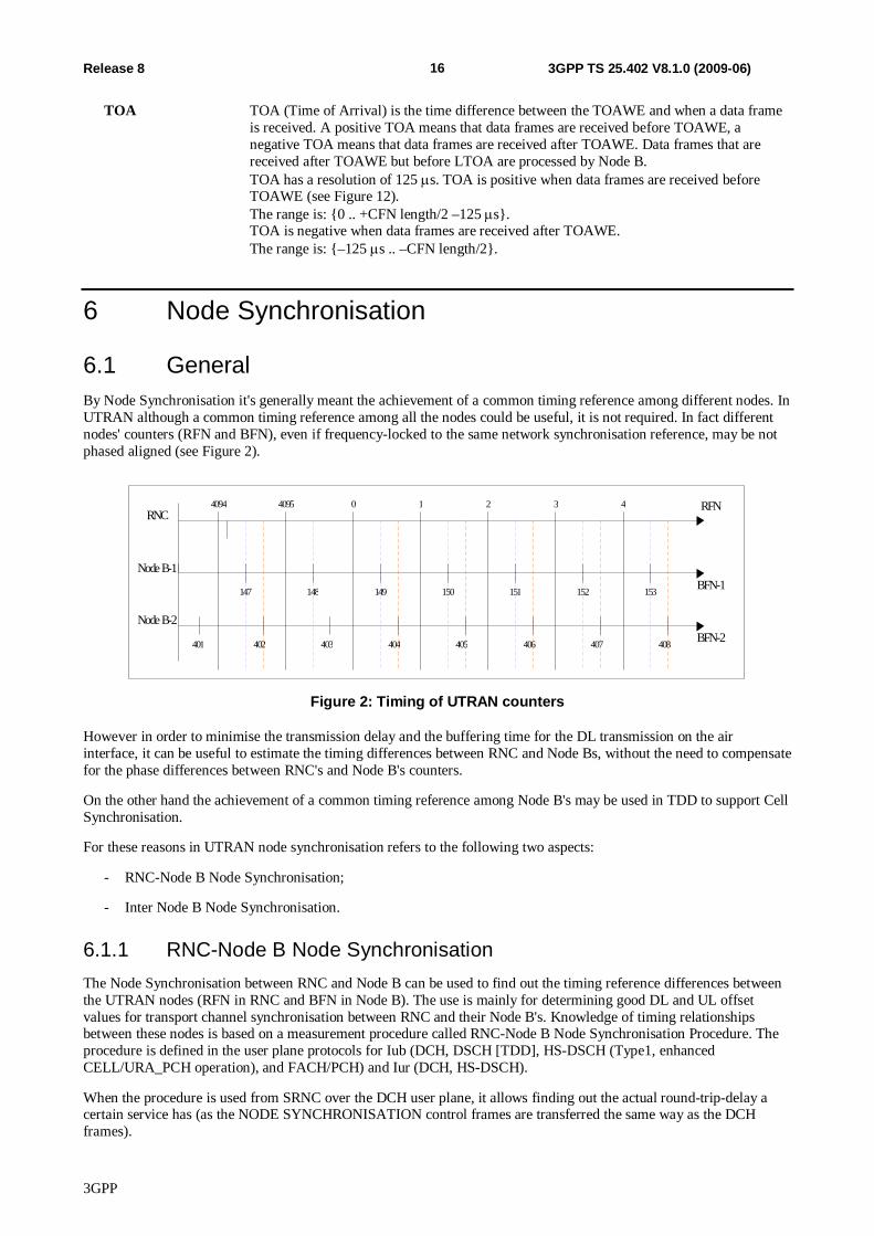
6.1 General By Node Synchronisation it's generally meant the achievement of a common timing reference among different nodes. In UTRAN although a common timing reference among all the nodes could be useful, it is not required. In fact different nodes' counters (RFN and BFN), even if frequency-locked to the same network synchronisation reference, may be not phased aligned (see Figure 2).
RNCRFN1 2 3 44094 4095 0
Node B-1BFN-1149 150 151 152 153147 148
Node B-2BFN-2404 405 406 407 408402 403401
Figure 2: Timing of UTRAN counters
However in order to minimise the transmission delay and the buffering time for the DL transmission on the air interface, it can be useful to estimate the timing differences between RNC and Node Bs, without the need to compensate for the phase differences between RNC's and Node B's counters.
On the other hand the achievement of a common timing reference among Node B's may be used in TDD to support Cell Synchronisation.
For these reasons in UTRAN node synchronisation refers to the following two aspects:
- RNC-Node B Node Synchronisation;
- Inter Node B Node Synchronisation.
6.1.1 RNC-Node B Node Synchronisation The Node Synchronisation between RNC and Node B can be used to find out the timing reference differences between the UTRAN nodes (RFN in RNC and BFN in Node B). The use is mainly for determining good DL and UL offset values for transport channel synchronisation between RNC and their Node B's. Knowledge of timing relationships between these nodes is based on a measurement procedure called RNC-Node B Node Synchronisation Procedure. The procedure is defined in the user plane protocols for Iub (DCH, DSCH [TDD], HS-DSCH (Type1, enhanced CELL/URA_PCH operation), and FACH/PCH) and Iur (DCH, HS-DSCH).
When the procedure is used from SRNC over the DCH user plane, it allows finding out the actual round-trip-delay a certain service has (as the NODE SYNCHRONISATION control frames are transferred the same way as the DCH frames).
3GPP
17 Release 8 3GPP TS 25.402 V8.1.0 (2009-06)
The procedure may also be carried out over a high priority transport bearer (beneficial when used between CRNC and Node Bs for the RNC-Node B Synchronisation purpose). Measurements of node offsets can be made at start or restart as well as during normal operation to supervise the stability of the nodes.
If an accurate Reference Timing Signal is used, the frequency deviation between nodes will be low, but could occur. If no accurate Reference Timing Signal is available, the local node reference oscillator must be relied upon. Then the RNC-Node B Node Synchronisation procedure can be used as a background process to find out the frequency deviation between nodes.
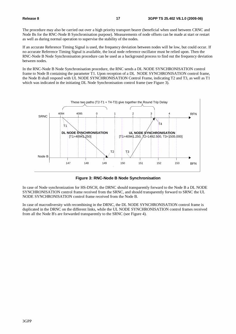
In the RNC-Node B Node Synchronisation procedure, the RNC sends a DL NODE SYNCHRONISATION control frame to Node B containing the parameter T1. Upon reception of a DL NODE SYNCHRONISATION control frame, the Node B shall respond with UL NODE SYNCHRONISATION Control Frame, indicating T2 and T3, as well as T1 which was indicated in the initiating DL Node Synchronisation control frame (see Figure 3).
SRNC
Node B BFN
RFN 1 2 3 4 4094 4095 0
149 150 151 152 153 147 148
DL NODE SYNCHRONISATION [T1=40941.250]
UL NODE SYNCHRONISATION [T1=40941.250, T2=1492.500, T3=1505.000]
T1
T2 T3
These two paths (T2-T1 + T4-T3) give together the Round Trip Delay (RTD)
T4
Figure 3: RNC-Node B Node Synchronisation
In case of Node synchronization for HS-DSCH, the DRNC should transparently forward to the Node B a DL NODE SYNCHRONISATION control frame received from the SRNC, and should transparently forward to SRNC the UL NODE SYNCHRONISATION control frame received from the Node B.
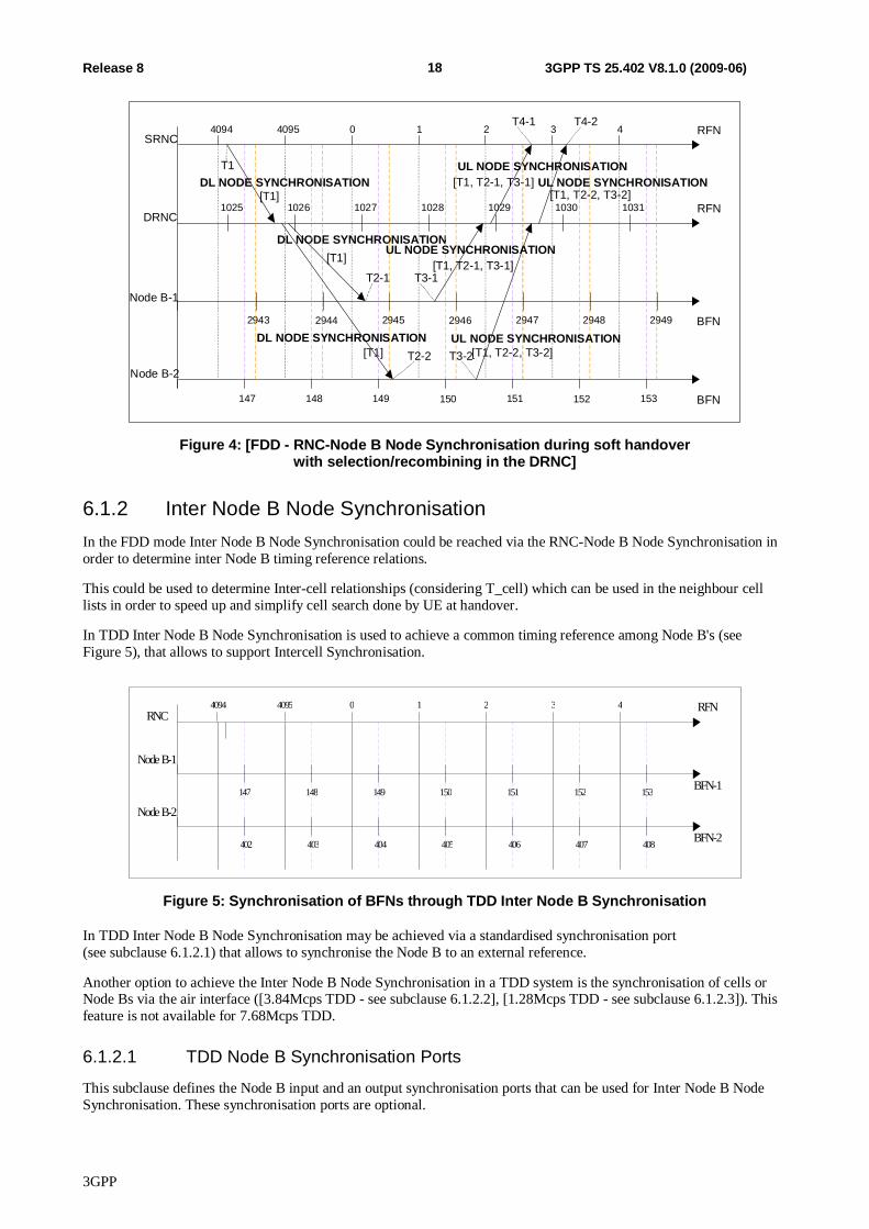
In case of macrodiversity with recombining in the DRNC, the DL NODE SYNCHRONISATION control frame is duplicated in the DRNC on the different links, while the UL NODE SYNCHRONISATION control frames received from all the Node B's are forwarded transparently to the SRNC (see Figure 4).
3GPP
18 Release 8 3GPP TS 25.402 V8.1.0 (2009-06)
DL NODE SYNCHRONISATION [T1]
SRNC
DL NODE SYNCHRONISATION [T1]
UL NODE SYNCHRONISATION [T1, T2-1, T3-1]
T2-2 T3-2
BFN 2945 2946 2947 2948 2949 2943 2944 Node B-1
RFN 1 2 3 4 4094 4095 0
T1
RFN 1028 1029 1030 1031 1025 1026 1027
BFN 149 150 151 152 153 147 148 Node B-2
DRNC
T2-1 T3-1
DL NODE SYNCHRONISATION [T1]
UL NODE SYNCHRONISATION [T1, T2-1, T3-1]
UL NODE SYNCHRONISATION [T1, T2-2, T3-2]
UL NODE SYNCHRONISATION [T1, T2-2, T3-2]
T4-1 T4-2
Figure 4: [FDD - RNC-Node B Node Synchronisation during soft handover with selection/recombining in the DRNC]
6.1.2 Inter Node B Node Synchronisation In the FDD mode Inter Node B Node Synchronisation could be reached via the RNC-Node B Node Synchronisation in order to determine inter Node B timing reference relations.
This could be used to determine Inter-cell relationships (considering T_cell) which can be used in the neighbour cell lists in order to speed up and simplify cell search done by UE at handover.
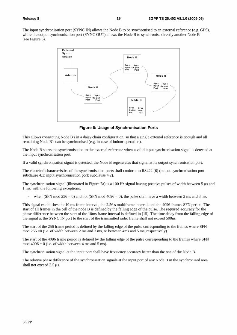
In TDD Inter Node B Node Synchronisation is used to achieve a common timing reference among Node B's (see Figure 5), that allows to support Intercell Synchronisation.
RNCRFN1 2 3 44094 4095 0
Node B-1
BFN-1149 150 151 152 153147 148
Node B-2
BFN-2404 405 406 407 408402 403
Figure 5: Synchronisation of BFNs through TDD Inter Node B Synchronisation
In TDD Inter Node B Node Synchronisation may be achieved via a standardised synchronisation port (see subclause 6.1.2.1) that allows to synchronise the Node B to an external reference.
Another option to achieve the Inter Node B Node Synchronisation in a TDD system is the synchronisation of cells or Node Bs via the air interface ([3.84Mcps TDD - see subclause 6.1.2.2], [1.28Mcps TDD - see subclause 6.1.2.3]). This feature is not available for 7.68Mcps TDD.
6.1.2.1 TDD Node B Synchronisation Ports
This subclause defines the Node B input and an output synchronisation ports that can be used for Inter Node B Node Synchronisation. These synchronisation ports are optional.
3GPP
19 Release 8 3GPP TS 25.402 V8.1.0 (2009-06)
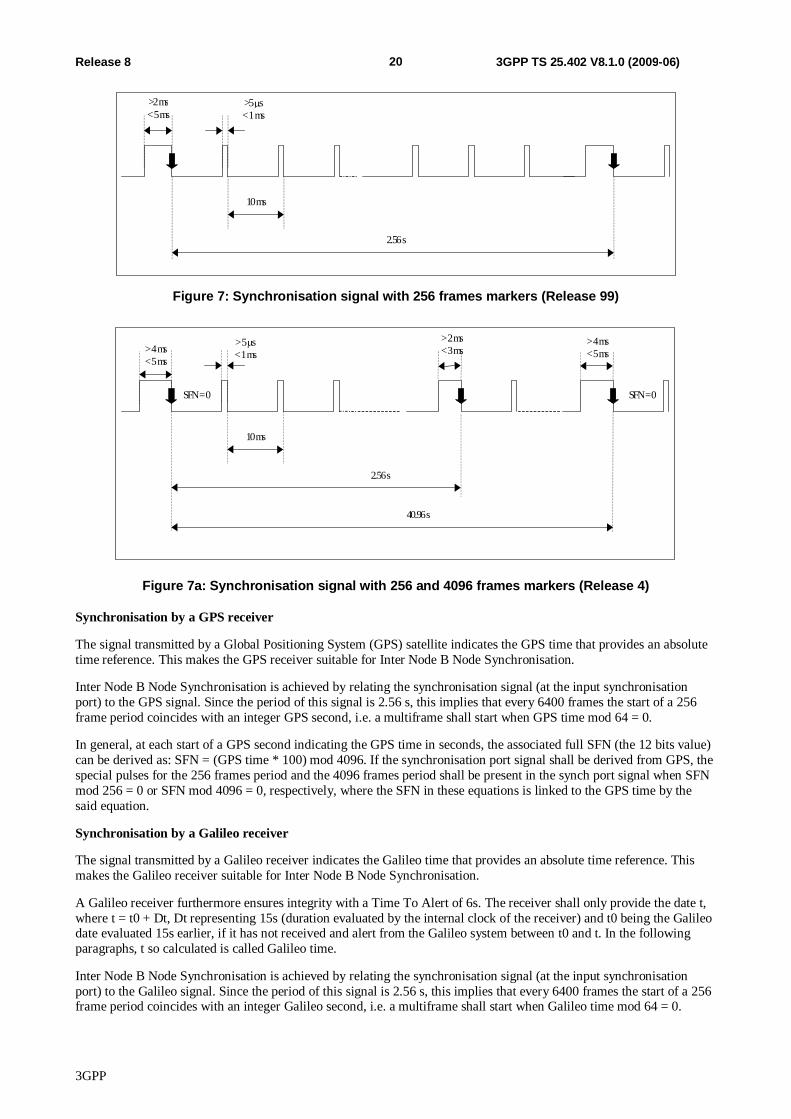
The input synchronisation port (SYNC IN) allows the Node B to be synchronised to an external reference (e.g. GPS), while the output synchronisation port (SYNC OUT) allows the Node B to synchronise directly another Node B (see Figure 6).
Syn cInp utPort
Syn cOu tput
Port
N ode B
Syn cInp utPort
Syn cOu tput
Por t
Node B
Syn cInp utPort
Syn cOu tput
Port
N ode B
Syn cOu tputPort
Syn cInp utPort
N ode B
A daptor
ExternalSync.Source
Figure 6: Usage of Synchronisation Ports
This allows connecting Node B's in a daisy chain configuration, so that a single external reference is enough and all remaining Node B's can be synchronised (e.g. in case of indoor operation).
The Node B starts the synchronisation to the external reference when a valid input synchronisation signal is detected at the input synchronisation port.
If a valid synchronisation signal is detected, the Node B regenerates that signal at its output synchronisation port.
The electrical characteristics of the synchronisation ports shall conform to RS422 [6] (output synchronisation port: subclause 4.1; input synchronisation port: subclause 4.2).
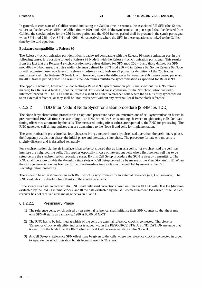
The synchronisation signal (illustrated in Figure 7a) is a 100 Hz signal having positive pulses of width between 5 s and 1 ms, with the following exceptions:
- when (SFN mod 256 = 0) and not (SFN mod 4096 = 0), the pulse shall have a width between 2 ms and 3 ms.
This signal establishes the 10 ms frame interval, the 2.56 s multiframe interval, and the 4096 frames SFN period. The start of all frames in the cell of the node B is defined by the falling edge of the pulse. The required accuracy for the phase difference between the start of the 10ms frame interval is defined in [15]. The time delay from the falling edge of the signal at the SYNC IN port to the start of the transmitted radio frame shall not exceed 500ns.
The start of the 256 frame period is defined by the falling edge of the pulse corresponding to the frames where SFN mod 256 =0 (i.e. of width between 2 ms and 3 ms, or between 4ms and 5 ms, respectively).
The start of the 4096 frame period is defined by the falling edge of the pulse corresponding to the frames where SFN mod 4096 = 0 (i.e. of width between 4 ms and 5 ms).
The synchronisation signal at the input port shall have frequency accuracy better than the one of the Node B.
The relative phase difference of the synchronisation signals at the input port of any Node B in the synchronised area shall not exceed 2.5 s.
3GPP
20 Release 8 3GPP TS 25.402 V8.1.0 (2009-06)
2.56 s
10 ms
>2 ms< 5 ms
>5 s< 1 ms
Figure 7: Synchronisation signal with 256 frames markers (Release 99)
2.56 s
10 ms
> 2 ms< 3 ms
> 5 s< 1 ms
40.96 s
> 4 ms< 5 ms
SFN = 0 SFN = 0
> 4 ms< 5 ms
Figure 7a: Synchronisation signal with 256 and 4096 frames markers (Release 4)
Synchronisation by a GPS receiver
The signal transmitted by a Global Positioning System (GPS) satellite indicates the GPS time that provides an absolute time reference. This makes the GPS receiver suitable for Inter Node B Node Synchronisation.
Inter Node B Node Synchronisation is achieved by relating the synchronisation signal (at the input synchronisation port) to the GPS signal. Since the period of this signal is 2.56 s, this implies that every 6400 frames the start of a 256 frame period coincides with an integer GPS second, i.e. a multiframe shall start when GPS time mod 64 = 0.
In general, at each start of a GPS second indicating the GPS time in seconds, the associated full SFN (the 12 bits value) can be derived as: SFN = (GPS time * 100) mod 4096. If the synchronisation port signal shall be derived from GPS, the special pulses for the 256 frames period and the 4096 frames period shall be present in the synch port signal when SFN mod 256 = 0 or SFN mod 4096 = 0, respectively, where the SFN in these equations is linked to the GPS time by the said equation.
Synchronisation by a Galileo receiver
The signal transmitted by a Galileo receiver indicates the Galileo time that provides an absolute time reference. This makes the Galileo receiver suitable for Inter Node B Node Synchronisation.
A Galileo receiver furthermore ensures integrity with a Time To Alert of 6s. The receiver shall only provide the date t, where t = t0 + Dt, Dt representing 15s (duration evaluated by the internal clock of the receiver) and t0 being the Galileo date evaluated 15s earlier, if it has not received and alert from the Galileo system between t0 and t. In the following paragraphs, t so calculated is called Galileo time.
Inter Node B Node Synchronisation is achieved by relating the synchronisation signal (at the input synchronisation port) to the Galileo signal. Since the period of this signal is 2.56 s, this implies that every 6400 frames the start of a 256 frame period coincides with an integer Galileo second, i.e. a multiframe shall start when Galileo time mod 64 = 0.
3GPP
21 Release 8 3GPP TS 25.402 V8.1.0 (2009-06)
In general, at each start of a Galileo second indicating the Galileo time in seconds, the associated full SFN (the 12 bits value) can be derived as: SFN = (Galileo time * 100) mod 4096. If the synchronisation port signal shall be derived from Galileo, the special pulses for the 256 frames period and the 4096 frames period shall be present in the synch port signal when SFN mod 256 = 0 or SFN mod 4096 = 0, respectively, where the SFN in these equations is linked to the Galileo time by the said equation.
Backward compatibility to Release 99
The Release 4 synchronisation port definition is backward compatible with the Release 99 synchronisation port in the following sense: It is possible to feed a Release 99 Node B with the Release 4 synchronisation port signal. This results from the fact that the Release 4 synchronisation port pulses defined for SFN mod 256 = 0 and those defined for SFN mod 4096 = 0 both meet the pulse width tolerance defined for SFN mod 256 = 0 in Release 99. So the Release 99 Node B will recognise these two classes of Release 4 pulses as valid Release 99 pulses for definition of the 256 frames multiframe start. The Release 99 Node B will, however, ignore the differences between the 256 frames period pulse and the 4096 frames period pulse: The result is the 256 frames multiframe synchronisation as specified for Release 99.
The opposite scenario, however, i.e. connecting a Release 99 synchronisation port signal (without the 4096 frames marker) to a Release 4 Node B, shall be excluded. This would cause confusion for the "synchronisation via radio interface" procedure. The TDD cells in Release 4 shall be either "reference" cells where the SFN is fully synchronised to an external reference, or they shall be "non-reference" without any external, local frame clock reference.
6.1.2.2 TDD Inter Node B Node Synchronisation procedure [3.84Mcps TDD]
The Node B synchronisation procedure is an optional procedure based on transmissions of cell synchronisation bursts in predetermined PRACH time slots according to an RNC schedule. Such soundings between neighbouring cells facilitate timing offset measurements by the cells. The measured timing offset values are reported to the RNC for processing. The RNC generates cell timing updates that are transmitted to the Node B and cells for implementation.
The synchronisation procedure has four phases to bring a network into a synchronised operation, the preliminary phase, the frequency acquisition phase, the initial phase and the steady-state phase. The procedure for late entrant cells is slightly different and is described separately.
For synchronisation via the air interface it has to be considered that as long as a cell is not synchronised the cell may interfere the neighbouring cells. This applies especially in case of late entrant cells where first the new cell has to be setup before the synchronisation procedure starts. By this Cell Setup procedure the SCH is already transmitting. The RNC shall therefore disable the downlink time slots on Cell Setup procedure by means of the Time Slot Status IE. When the cell synchronisation has been performed the downlink time slots shall be enabled by means of the Cell Reconfiguration procedure.
There should be at least one cell in each RNS which is synchronised by an external reference (e.g. GPS receiver). The RNC evaluates the absolute time thanks to these reference cells.
If the source is a Galileo receiver, the RNC shall only send corrections based on time t = t0 + Dt with Dt = 15s (duration evaluated by the RNC’s internal clock), and t0 the date evaluated by the Galileo measurement 15s earlier, if the Galileo receiver has not received alert message between t0 and t.
6.1.2.2.1 Preliminary Phase
1) The reference cells, synchronised by an external reference, shall initialise their SFN counter so that the frame with SFN=0 starts on January 6, 1980 at 00:00:00 GMT.
2) The RNC has to be informed at which of the cells the external reference clock is connected. Therefore, a 'Reference Clock availability' indicator is added within the RESOURCE STATUS INDICATION message that is sent from the Node B to the RNC when a Local Cell becomes existing at the Node B.
3) At Cell Setup a 'Reference SFN offset' may be given to the cells where the reference clock is connected in order to separate the synchronisation bursts from different RNC areas.
3GPP
22 Release 8 3GPP TS 25.402 V8.1.0 (2009-06)
4) The RNC has to retrieve the reference time from the cells with the reference clock. For the reference time retrieval the DL Transport Channels Synchronisation procedure or the Node Synchronisation procedure on the PCH frame protocol (see [4]) shall be used. The Node B shall consider the SFN derived from the synchronisation port and the Reference SFN offset given by the RNC.
5) Now the RNC proceeds by updating the timing of all the remaining cells in the RNS, instructing them to adjust their clocks. Therefore, first the DL Transport Channels Synchronisation procedure on the PCH frame protocol shall be performed in order to determine the deviation from the reference SFN. The RNC then sends a CELL SYNCHRONISATION ADJUSTMENT REQUEST message to all the cells for SFN update, apart from the one(s) containing the reference clock. The cells shall adjust their SFN and frame timing accordingly.
6.1.2.2.1A Frequency Acquisition Phase
The frequency acquisition phase is used to bring cells of an RNS area to within frequency limits prior to initial synchronisation. No traffic is supported during this phase.
1) The cell(s) identified as reference cell, i.e. external reference clock is connected to, shall transmit continuously cell synchronisation bursts in every time slot where possible according to the information's given in the CELL SYNCHRONISATION INITIATION REQUEST message.
2) All other cells are considered as unlocked (i.e. not in frequency lock) shall listen for transmission from other cells and perform frequency locking to any transmission received. For setting the parameters within the Node B to listen for transmission from other cells, the CELL SYNCHRONISATION INITIATION REQUEST message is used.
3) A cell shall signal completion of frequency acquisition to the RNC, as soon as it has locked its frequency to the received signal, fulfilling the Frequency Stability requirement set in [17].
4) If the cell(s) have received transmission request on instructing the frequency acquisition and the cell(s) have performed frequency locking, the cell(s) shall begin transmitting the specified code for frequency locking of other cells.
5) When the RNC has received completion of frequency acquisition signals from all cells the frequency acquisition phase is completed.
6.1.2.2.1B Initial Phase
The procedure for initial synchronisation is used to bring cells of an RNS area into synchronisation at network start up. No traffic is supported during this phase.
1) For the synchronisation procedure it is useful to know which cells can “hear” each other. Therefore, all cells are instructed to transmit their cell synchronisation bursts in turn one after the other. The same cell synchronisation burst code and code offset is used by all cells.
2) Each cell shall listen for transmissions from other cells. Each cell shall report the timing and received SIR of successfully detected cell sync bursts to the RNC.
3) Upon reception of a CELL SYNCHRONISATION ADJUSTMENT message the cell shall adjust its timing accordingly. The timing adjustment shall be completed before the CELL SYNCHRONISATION ADJUSTMENT RESPONSE message is sent. It shall be implemented by adjusting the timing and/or tuning the clock frequency.
4) Steps 1 to 3 are repeated as often as necessary in order to reach the minimum synchronisation accuracy defined in [16]. This serves the purpose to bring the network into tight synchronisation. The SIR value within the cell sync burst reports is used by the RNC to define the schedule for the steady-state phase. I.e. to define when which cells transmit a cell synchronisation burst and when which cell synchronisation bursts shall be received. Cells which are sufficiently separated can be allowed to send the same cell synchronisation burst at the same time. Cells which are not sufficiently separated have to use different cell synchronisation codes and code offsets for distinctions.
3GPP
23 Release 8 3GPP TS 25.402 V8.1.0 (2009-06)
6.1.2.2.2 Steady-State Phase
The steady-state phase allows cells to reach and/or maintain the required synchronisation accuracy. With the start of the steady-state phase traffic is supported in a cell. The steady-state phase starts with the Cell Synchronisation Reconfiguration procedure (see [3]) which defines the synchronisation schedule. I.e. each cell gets the information when to transmit a cell synchronisation burst and when the individual cell synchronisation bursts from the neighbouring cells shall be measured.
For definition of the SFN when the cell shall transmit or receive cell synchronisation bursts, the SFN period is divided into cycles that have the same schedule. Within each cycle the Frame numbers for the cell synchronisation bursts are calculated by the number of repetitions per cycle and by an offset. Code and code offset are used to identify the individual cell synchronisation bursts.
1) The cell shall transmit a cell synchronisation burst and measure cell synchronisation bursts from neighbouring cells according to the information's given in the CELL SYNCHRONISATION RECONFIGURATION REQUEST message. Reception times for all relevant codes and code offsets shall be reported to the RNC with the CELL SYNCHRONISATION REPORT message.
2) Upon determination of an error in timing, the RNC adjusts the cell timing by means of the CELL SYNCHRONISATION ADJUSTMENT message. The timing adjustment shall be started at the beginning of the frame with the SFN given in the command. It shall be completed by the next cell synchronisation slot. Timing adjustments shall be implemented via gradual steps at the beginning of a frame. The whole adjustment shall be implemented with maximum stepsize of one sample per frame.
3) Step 1 and 2 continue indefinitely
6.1.2.2.3 Late-Entrant Cells
The scheme for introducing new cells into a synchronised RNS is as follows:
1) Late entrant cells (new cells being added without reference clock ) or cells recovering from unavailability shall first be roughly synchronised. Therefore, first the DL Transport Channels Synchronisation procedure on the PCH frame protocol shall be performed in order to determine the deviation from the reference SFN. The RNC then sends a CELL SYNCHRONISATION ADJUSTMENT message to the late-entrant cells for SFN update.
2) Frequency acquisition of the late entrant cell is started by instructing the late entrant cell first to listen to the regular schedule of cell sync bursts of the surrounding cells. The transmission schedule of the surrounding cells shall be signalled to the late entrant cell within the CELL SYNCHRONISATION INITIATION REQUEST message. Frequency locking is reported using the CELL SYNCHRONISATION REPORT message.
3) In addition or instead of a regular schedule a single common cell synchronisation burst is transmitted in parallel by cells which are synchronised in the system and which are preferably the ones surrounding the late-entrant cell. The single cell synchronisation burst is initiated by means of the CELL SYNCHRONISATION INITIATION REQUEST message to the surrounding cells.
4) The late entrant cell shall correlate against the cell synchronisation burst according to the measurement information within the CELL SYNCHRONISATION INITIATION REQUEST message. The reception window shall be +/- 3 frames around the SFN frame given in the measurement information. The late entrant cell shall take the earliest reception as the timing of the system and adjusts its own timing and SFN number accordingly.
5) Thereafter, the late entrant cell shall start regular measurements after the reception of a CELL SYNCHRONISATION RECONFIGURATION REQUEST message and it shall report the timing of the measured cell synchronisation bursts to the RNC. In turn, the late entrant cell receives its own schedules for synchronisation transmissions and receptions and enters the steady-state phase.
6.1.2.3 TDD Inter Node B Node Synchronisation procedure [1.28Mcps TDD]
The Node B synchronization procedure for 1.28 Mcps TDD is an optional procedure based on the usage of the transmissions of the DwPCH to achieve Node B synchronisation over the air.
The main difference to the corresponding procedure for 3.84 Mcps TDD is the use of the DwPCH instead of the PRACH for synchronisation burst transmission and reception.
In addition, some extensions for the Steady State phase compared to the 3.84Mcps TDD solution have been specified:
3GPP
24 Release 8 3GPP TS 25.402 V8.1.0 (2009-06)
- The ability to perform averaging of correlation results of several received SYNC_DL codes within a Synchronisation Cycle;
- The ability of the cell to perform self-adjustment of the timing based on measurements, and to report the accumulated adjustments to the RNC.
The synchronization procedure has three phases to bring a network into a synchronized operation, the preliminary phase, the initial phase and the steady-state phase. In addition there is a procedure for late entrant cells.
For synchronisation via the air interface it has to be considered that as long as a cell is not synchronised the cell may interfere the neighbouring cells. This applies especially in case of late entrant cells where first the new cell has to be setup before the synchronisation procedure starts. The RNC shall therefore disable the downlink time slots on Cell Setup procedure by means of the Time Slot Status IE. When the cell synchronisation has been performed the downlink time slots shall be enabled by means of the Cell Reconfiguration procedure.
There should be at least one cell in each RNS which is synchronised by an external reference (e.g. GPS receiver). The RNC evaluates the absolute time thanks to these "master cells".
If the source is a Galileo receiver, the RNC shall only send corrections based on time t = t0 + Dt with Dt = 15s (duration evaluated by the RNC’s internal clock), and t0 the date evaluated by the Galileo measurement 15s earlier, if the Galileo receiver has not received alert message between t0 and t.
6.1.2.3.1 Preliminary Phase
1) The "master cells", synchronised by an external reference, shall initialise their SFN counter so that the frame with SFN=0 starts on January 6, 1980 at 00:00:00 GMT.
2) The RNC has to be informed which of the cells are master cells. Therefore, a "Reference Clock availability" indicator is added within the RESOURCE STATUS INDICATION message that is sent from the Node B to the RNC when a Local Cell becomes existing at the Node B.
3) At Cell Setup a "Reference SFN offset" may be given to the cells where the reference clock is connected in order to separate the synchronisation bursts from different RNC areas.
4) The RNC has to retrieve the reference time from the cells with reference clock. For the reference time retrieval the DL Transport Channels Synchronisation procedure or the Node Synchronisation procedure on the PCH frame protocol (see [4]) shall be used. The Node B shall consider the SFN derived from the synchronisation port and the Reference SFN offset given by the RNC.
5) Now the RNC proceeds by updating the timing of all the remaining cells in the RNS, instructing them to adjust their clocks. Therefore, first the DL Transport Channels Synchronisation procedure or the Node Synchronisation procedure on the PCH frame protocol shall be performed in order to determine the deviation from the reference SFN. The RNC then sends a CELL SYNCHRONISATION ADJUSTMENT REQUEST message to all the cells for SFN update, apart from the one(s) containing the reference clock. The cells shall adjust their SFN and frame timing accordingly.
6.1.2.3.2 Initial Phase
The procedure for initial synchronization is used to bring cells of an RNS area into synchronization at a network start up. No traffic is supported during this phase:
1) For the synchronisation procedure it is useful to know which cells can "hear" each other. Therefore, all cells are instructed to transmit their SYNC_DL Codes one-at-a-time.
2) Each cell shall listen to transmissions from other cells based on RNC schedule for initial synchronisation. The SYNC_DL sequence is transmitted continuously throughout each radio frame period. Each cell shall report the timing and received S/(N+I) of successfully detected SYNC_DL codes to the RNC.
3) Upon reception of a CELL SYNCHRONISATION ADJUSTMENT message the cell shall adjust its timing accordingly. The timing adjustment shall be completed before the CELL SYNCHRONISATION ADJUSTMENT RESPONSE message is sent. It shall be implemented by adjusting the timing and/or tuning the clock frequency.
3GPP
25 Release 8 3GPP TS 25.402 V8.1.0 (2009-06)
4) Steps 1 to 3 are repeated as often as necessary in order to reach the minimum synchronisation accuracy defined in [16]. This serves the purpose to bring the network into tight synchronisation. The rapid updates allow the correction of the clock frequencies as well as the clock timings to be adjusted in a short timeframe. This rapidly brings the network into tight synchronization. The S/(N+I) values are used to define the schedule for the steady-state phase. Cells which are sufficiently separated or use different frequency bands can be allowed to send the same SYNC_DL code at the same time. Cells which are not sufficiently separated have to use different SYNC_DL codes for distinctions.
6.1.2.3.3 Steady-State Phase
The steady-state phase allows the system to reach or maintain the required synchronization accuracy. There is a "basic method", and there are extensions which may be required under adverse circumstances, to achieve reliable measurements of SYNC_DL codes from neighbour cells, and to achieve immediate, fast timing corrections while reducing the Iub interface signalling load.
6.1.2.3.3.1 Basic method
With the start of the steady-state phase traffic is supported in a cell. The steady-state phase starts with the Cell Synchronisation Reconfiguration procedure (see [3]) which defines the synchronisation schedule. I.e. each cell gets the information when to transmit a SYNC_DL code and when the individual SYNC_DL codes from the neighbouring cells shall be measured.
For definition of the "Synchronisation Frames", i.e. the SFNs when the cell shall transmit or receive SYNC_DL codes, the SFN period is divided into Synchronisation Cycles that include the same number of Synchronisation Frames. The interval from one Synchronisation Frame to the next is called a Repetition Period. Each Synchronisation Cycle has the same transmit and receive schedule.
To be specific, the SFNs which are used as Synchronisation Frames are calculated from the "Number of cycles per SFN period" and the "Number of Repetitions per Cycle" as follows (where Repetition Period may be a non-integer number):
Cycle length: 4096 / value of the IE ‘Number of cycles per SFN period’
Repetition period: Cycle length / value of IE ‘Number of repetitions per cycle period’
Synchronisation Frame SFN = floor ((k-1) * Cycle length + (i-1)* Repetition period)
k = {1, 2, 3, .. Number of cycle per SFN period} = cycle counter
i = {1, 2, 3, .. Number of repetitions within cycle period} = Repetition counter
This provides the set of Synchronisation Frames SFN within the SFN period or 4096 frames. Then the procedure works as follows:
1) Each of the cells transmits its own predetermined SYNC_DL sequence on the DwPCH and receives the specific SYNC_DL code of neighbouring cells according to the information given in the CELL SYNCHRONISATION RECONFIGURATION REQUEST message. All cells shall report the reception timing for each specific SYNC_DL code to the RNC with the CELL SYNCHRONISATION REPORT message.
2) Upon determination of an error in timing, the RNC adjusts the cell timing by means of the CELL SYNCHRONISATION ADJUSTMENT message. The timing adjustment shall be started at the beginning of the frame with the SFN given in the command. It shall be completed by the next cell synchronisation slot. Timing adjustments shall be implemented via gradual steps at the beginning of a frame. The whole adjustment shall be implemented with maximum stepsize of one sample per frame.
3) Steps 1 and 2 continue indefinitely.
6.1.2.3.3.2 Extended method
The following extensions of the basic scheme are available: Averaging of measurements, and self-adjustment of the radio interface timing.
1) Averaging of measurements: For increasing the S/(N+I) values of measured SYNC_DL codes, it shall be possible for a cell to apply an averaging of SYNC_DL codes received from the same neighbouring cell, before deriving the receive timing from the correlation result. – During the averaging period, the timing in the neighbouring cells
3GPP
26 Release 8 3GPP TS 25.402 V8.1.0 (2009-06)
transmitting the SYNC_DL codes should be “frozen” in order to avoid “blurring” of the averaged measurements. – This optional averaging is supported by subdividing the Synchronisation Cycles into a number of "Subcycles" where in each Subcycle, a full set of SYNC_DL samples is received, and by averaging over the subcycles, such that at the end of a Synchronisation Cycle a full set of timing deviation measurements with improved S/(N+I) is available. The number of subcycles is configured by the CRNC.
This introduction of "Subcycles" implies a change in the equations how to calculate the Synchronisation Frames SFN: The Number of subcycles per cycle period IE is taken into account as follows:
Cycle length: 4096 / value of the IE ‘Number of cycles per SFN period’
Subcycle length: Cycle length / value of IE ‘Number of subcycles per cycle period’
Repetition period: Subcycle length / value of IE ‘Number of repetitions per subcycle period’
Synchronisation Frame SFN = floor ((k-1) * Cycle length + (I-1)* Repetition period)
k = {1, 2, 3, .. Number of cycle per SFN period} = cycle counter
j = {1, 2, 3, .. Number of subcycles per cycle} = subcycle counter
I = {1, 2, 3, .. Number of repetitions within cycle period} = Repetition counter
This provides the set of Synchronisation Frames SFN within the SFN period of 4096 frames.
NOTE 1: Subcycle length and Repetiton period can have non-integer values.
NOTE 2: If the number of subcycles per cycle is set to unity, the "subcycles" are identitical to the "cycles", and no averaging occurs.
At the end of each Cycle, a full set of Time of Arrival measurements is available, with or without averaging. So these measurements can be further processed as in the basic method.
2) Self-adjustment of the radio interface timing: It should be possible for the RNC to allow the Node B to perform a timing correction based on its own measurements autonomously without requiring the RNC to calculate the amount of timing correction. This reduces the amount of Iub interface signalling while allowing for fast corrections of timing deviations. – So the RNC shall indicate the possibility of self-adjustment, by including a Propagation Delay Compensation IE into the CELL SYNCHRONISATION RECONFIGURATION message, in addition to the SYNC_DL code to measure. Whenever this optional IE is present, the Node B should use the respective SYNC_DL measurement (after potential averaging) to perform the self-adjustment at the end of a Synchronisation Cycle. – Whenever this IE is not present, no self-adjustment shall be performed. – In each measurement report where the Node B reports the measured Time of Arrival values, the Node B shall also include the accumulated phase adjustments since the last measurement report to the RNC for surveillance purposes.
6.1.2.3.4 Late-Entrant Cells
The scheme for introducing new cells into a synchronized RNS is as follows:
1) Late-entrant cells (new cells being added without reference clock) or cells recovering from unavailability shall first be roughly synchronised via Iub interface messages. Therefore, first the DL Transport Channels Synchronisation procedure or the Node Synchronisation procedure on the PCH frame protocol shall be performed in order to determine the deviation from the reference SFN. The RNC then sends a CELL SYNCHRONISATION ADJUSTMENT message to the late-entrant cells for SFN update.
2) The RNC should tell the late-entrant which SYNC_DL codes and carrier frequencies to listen for, corresponding to its neighbour cells signalled within the CELL SYNCHRONISATION RECONFIGURATION REQUEST message.
3) The late entrant then reports the timing of the SYNC_DL codes using the CELL SYNCHRONISATION REPORT message. The RNC knows the location of all cells and therefore should be able to compute a timing adjustment for the late-entrant that takes into account the expected propagation delays between the late-entrant and its neighbouring cells The RNC adjusts the cell and the cycle is repeated until the RNC is satisfied that the cell’s timing accuracy fulfills the requirements to be allowed to enter the Steady State phase.
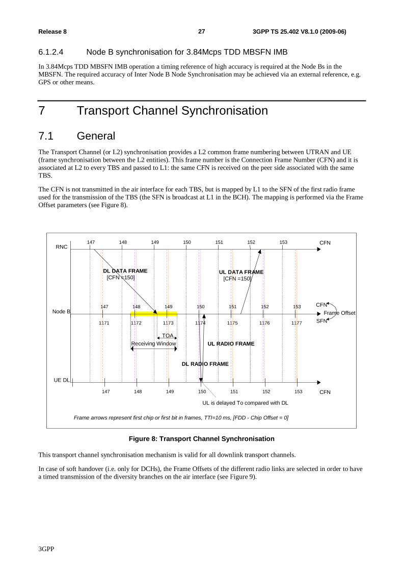
3GPP
27 Release 8 3GPP TS 25.402 V8.1.0 (2009-06)
6.1.2.4 Node B synchronisation for 3.84Mcps TDD MBSFN IMB
In 3.84Mcps TDD MBSFN IMB operation a timing reference of high accuracy is required at the Node Bs in the MBSFN. The required accuracy of Inter Node B Node Synchronisation may be achieved via an external reference, e.g. GPS or other means.
7 Transport Channel Synchronisation
7.1 General The Transport Channel (or L2) synchronisation provides a L2 common frame numbering between UTRAN and UE (frame synchronisation between the L2 entities). This frame number is the Connection Frame Number (CFN) and it is associated at L2 to every TBS and passed to L1: the same CFN is received on the peer side associated with the same TBS.
The CFN is not transmitted in the air interface for each TBS, but is mapped by L1 to the SFN of the first radio frame used for the transmission of the TBS (the SFN is broadcast at L1 in the BCH). The mapping is performed via the Frame Offset parameters (see Figure 8).
RNC
Node B
CFN 150 151 152 153 147 148 149
1173 1174 1175 1176 1177 1171 1172
DL DATA FRAME [CFN =150]
Receiving Window TOA
UE DL CFN 149 150 151 152 153 147 148
DL RADIO FRAME
UL RADIO FRAME
UL DATA FRAME [CFN =150]
149 150 151 152 153 147 148
SFN
CFN Frame Offset
Frame arrows represent first chip or first bit in frames, TTI=10 ms, [FDD - Chip Offset = 0]
UL is delayed To compared with DL
Figure 8: Transport Channel Synchronisation
This transport channel synchronisation mechanism is valid for all downlink transport channels.
In case of soft handover (i.e. only for DCHs), the Frame Offsets of the different radio links are selected in order to have a timed transmission of the diversity branches on the air interface (see Figure 9).
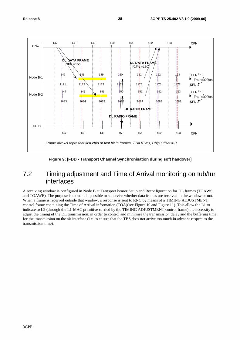
3GPP
28 Release 8 3GPP TS 25.402 V8.1.0 (2009-06)
Node B-2
SFN-2 1685 1686 1687 1688 1689 1683 1684
CFN 149 150 151 152 153 147 148
Node B-1
SFN-1 1173 1174 1175 1176 1177 1171 1172
CFN 149 150 151 152 153 147 148
RNC CFN 150 151 152 153 147 148 149
DL DATA FRAME [CFN =150]
DL RADIO FRAME UL RADIO FRAME
UL DATA FRAME [CFN =150]
UE DL
CFN 149 150 151 152 153 147 148
Frame Offset
Frame Offset
Frame arrows represent first chip or first bit in frames, TTI=10 ms, Chip Offset = 0
Figure 9: [FDD - Transport Channel Synchronisation during soft handover]
7.2 Timing adjustment and Time of Arrival monitoring on Iub/Iur interfaces
A receiving window is configured in Node B at Transport bearer Setup and Reconfiguration for DL frames (TOAWS and TOAWE). The purpose is to make it possible to supervise whether data frames are received in the window or not. When a frame is received outside that window, a response is sent to RNC by means of a TIMING ADJUSTMENT control frame containing the Time of Arrival information (TOA)(see Figure 10 and Figure 11). This allow the L1 to indicate to L2 (through the L1-MAC primitive carried by the TIMING ADJUSTMENT control frame) the necessity to adjust the timing of the DL transmission, in order to control and minimise the transmission delay and the buffering time for the transmission on the air interface (i.e. to ensure that the TBS does not arrive too much in advance respect to the transmission time).
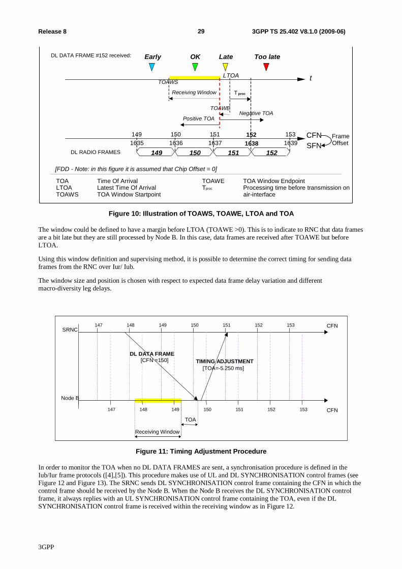
3GPP
29 Release 8 3GPP TS 25.402 V8.1.0 (2009-06)
T proc
150 149 DL RADIO FRAMES 151 152
Early
t
DL DATA FRAME #152 received: OK Too late
LTOA
Late
Receiving Window
TOAWS
TOAWE
Positive TOA Negative TOA
TOA Time Of Arrival LTOA Latest Time Of Arrival TOAWS TOA Window Startpoint
TOAWE TOA Window Endpoint T proc Processing time before transmission on
air-interface
CFN SFN
149 150 151 152 153 1635 1636 1637 1638 1639
FrameOffset
[FDD - Note: in this figure it is assumed that Chip Offset = 0]
Figure 10: Illustration of TOAWS, TOAWE, LTOA and TOA
The window could be defined to have a margin before LTOA (TOAWE >0). This is to indicate to RNC that data frames are a bit late but they are still processed by Node B. In this case, data frames are received after TOAWE but before LTOA.
Using this window definition and supervising method, it is possible to determine the correct timing for sending data frames from the RNC over Iur/ Iub.
The window size and position is chosen with respect to expected data frame delay variation and different macro-diversity leg delays.
SRNC
Node B CFN
CFN 150 151 152 153 147 148 149
149 150 151 152 153 147 148
DL DATA FRAME [CFN =150] TIMING ADJUSTMENT
[TOA=-5.250 ms]
Receiving Window TOA
Figure 11: Timing Adjustment Procedure
In order to monitor the TOA when no DL DATA FRAMES are sent, a synchronisation procedure is defined in the Iub/Iur frame protocols ([4],[5]). This procedure makes use of UL and DL SYNCHRONISATION control frames (see Figure 12 and Figure 13). The SRNC sends DL SYNCHRONISATION control frame containing the CFN in which the control frame should be received by the Node B. When the Node B receives the DL SYNCHRONISATION control frame, it always replies with an UL SYNCHRONISATION control frame containing the TOA, even if the DL SYNCHRONISATION control frame is received within the receiving window as in Figure 12.
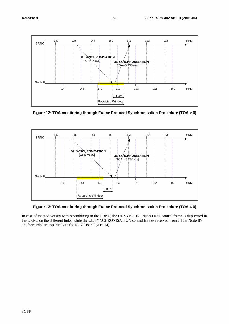
3GPP
30 Release 8 3GPP TS 25.402 V8.1.0 (2009-06)
SRNC
Node B CFN
CFN 150 151 152 153 147 148 149
149 150 151 152 153 147 148
DL SYNCHRONISATION [CFN =151] UL SYNCHRONISATION
[TOA=5.750 ms]
Receiving Window TOA
Figure 12: TOA monitoring through Frame Protocol Synchronisation Procedure (TOA > 0)
SRNC
Node B CFN
CFN 150 151 152 153 147 148 149
149 150 151 152 153 147 148
DL SYNCHRONISATION [CFN =150] UL SYNCHRONISATION
[TOA=-5.250 ms]
Receiving Window TOA
Figure 13: TOA monitoring through Frame Protocol Synchronisation Procedure (TOA < 0)
In case of macrodiversity with recombining in the DRNC, the DL SYNCHRONISATION control frame is duplicated in the DRNC on the different links, while the UL SYNCHRONISATION control frames received from all the Node B's are forwarded transparently to the SRNC (see Figure 14).
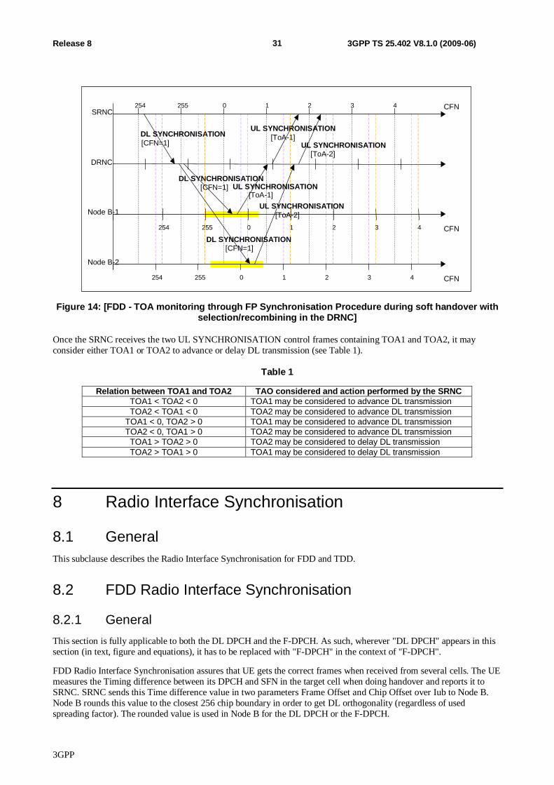
3GPP
31 Release 8 3GPP TS 25.402 V8.1.0 (2009-06)
DL SYNCHRONISATION [CFN=1]
SRNC
DL SYNCHRONISATION [CFN=1]
UL SYNCHRONISATION [ToA-1]
CFN 0 1 2 3 4 254 255 Node B-1
CFN 1 2 3 4 254 255 0
CFN 0 1 2 3 4 254 255 Node B-2
DRNC
DL SYNCHRONISATION [CFN=1]
UL SYNCHRONISATION [ToA-1]
UL SYNCHRONISATION [ToA-2]
UL SYNCHRONISATION [ToA-2]
Figure 14: [FDD - TOA monitoring through FP Synchronisation Procedure during soft handover with selection/recombining in the DRNC]
Once the SRNC receives the two UL SYNCHRONISATION control frames containing TOA1 and TOA2, it may consider either TOA1 or TOA2 to advance or delay DL transmission (see Table 1).
Table 1
Relation between TOA1 and TOA2 TAO considered and action performed by the SRNC TOA1 < TOA2 < 0 TOA1 may be considered to advance DL transmission TOA2 < TOA1 < 0 TOA2 may be considered to advance DL transmission
TOA1 < 0, TOA2 > 0 TOA1 may be considered to advance DL transmission TOA2 < 0, TOA1 > 0 TOA2 may be considered to advance DL transmission TOA1 > TOA2 > 0 TOA2 may be considered to delay DL transmission TOA2 > TOA1 > 0 TOA1 may be considered to delay DL transmission
8 Radio Interface Synchronisation
8.1 General This subclause describes the Radio Interface Synchronisation for FDD and TDD.
8.2 FDD Radio Interface Synchronisation
8.2.1 General This section is fully applicable to both the DL DPCH and the F-DPCH. As such, wherever "DL DPCH" appears in this section (in text, figure and equations), it has to be replaced with "F-DPCH" in the context of "F-DPCH".
FDD Radio Interface Synchronisation assures that UE gets the correct frames when received from several cells. The UE measures the Timing difference between its DPCH and SFN in the target cell when doing handover and reports it to SRNC. SRNC sends this Time difference value in two parameters Frame Offset and Chip Offset over Iub to Node B. Node B rounds this value to the closest 256 chip boundary in order to get DL orthogonality (regardless of used spreading factor). The rounded value is used in Node B for the DL DPCH or the F-DPCH.
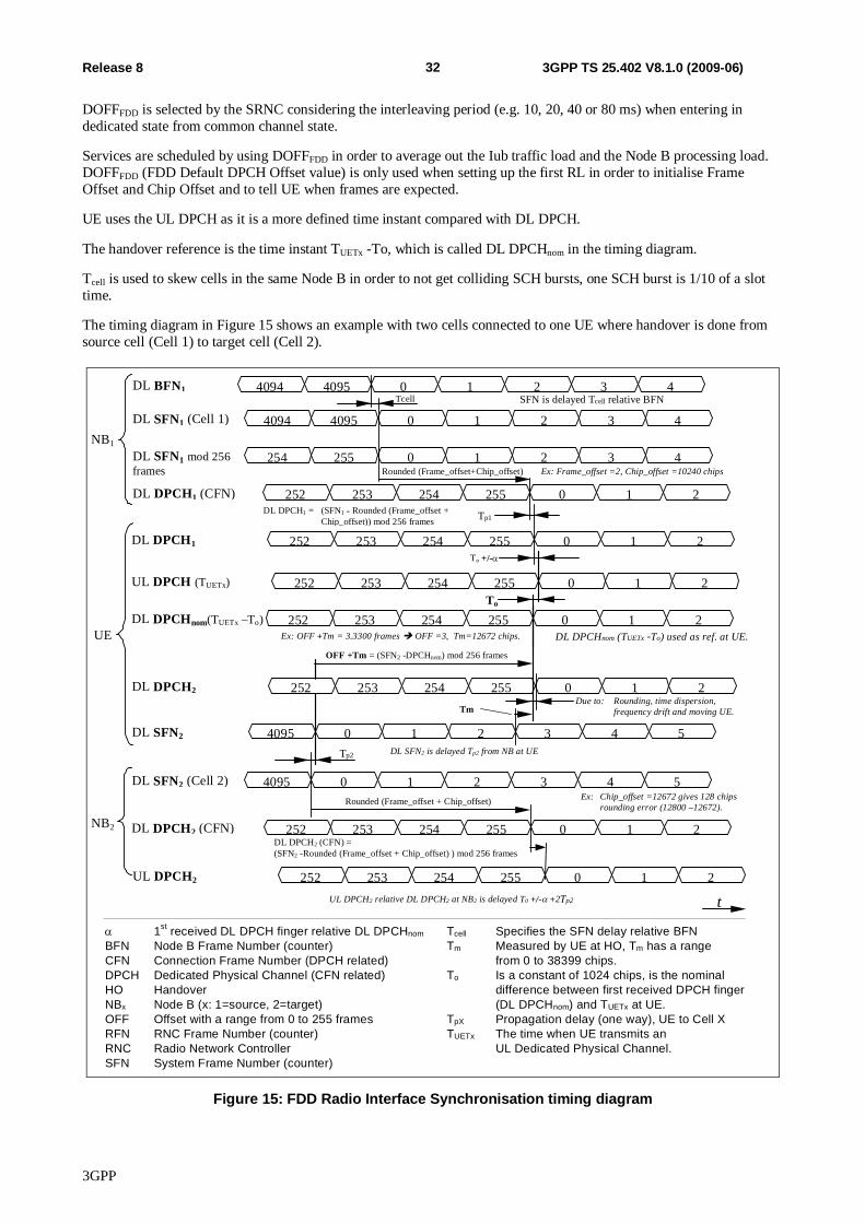
3GPP
32 Release 8 3GPP TS 25.402 V8.1.0 (2009-06)
DOFFFDD is selected by the SRNC considering the interleaving period (e.g. 10, 20, 40 or 80 ms) when entering in dedicated state from common channel state.
Services are scheduled by using DOFFFDD in order to average out the Iub traffic load and the Node B processing load. DOFFFDD (FDD Default DPCH Offset value) is only used when setting up the first RL in order to initialise Frame Offset and Chip Offset and to tell UE when frames are expected.
UE uses the UL DPCH as it is a more defined time instant compared with DL DPCH.
The handover reference is the time instant TUETx -To, which is called DL DPCHnom in the timing diagram.
Tcell is used to skew cells in the same Node B in order to not get colliding SCH bursts, one SCH burst is 1/10 of a slot time.
The timing diagram in Figure 15 shows an example with two cells connected to one UE where handover is done from source cell (Cell 1) to target cell (Cell 2).
OFF +Tm = (SFN2 -DPCHnom) mod 256 frames
To
1
Rounded (Frame_offset + Chip_offset)
0
Tp2
t
Tp1
1st received DL DPCH finger relative DL DPCHnom
BFN Node B Frame Number (counter)CFN Connection Frame Number (DPCH related)DPCH Dedicated Physical Channel (CFN related)HO HandoverNBx Node B (x: 1=source, 2=target)OFF Offset with a range from 0 to 255 framesRFN RNC Frame Number (counter)RNC Radio Network ControllerSFN System Frame Number (counter)
Tcell Specifies the SFN delay relative BFNTm Measured by UE at HO, Tm has a range
from 0 to 38399 chips.To Is a constant of 1024 chips, is the nominal
difference between first received DPCH finger(DL DPCHnom) and TUETx at UE.
TpX Propagation delay (one way), UE to Cell XTUETx The time when UE transmits an
UL Dedicated Physical Channel.
Ex: OFF +Tm = 3.3300 frames OFF =3, Tm=12672 chips.
Tcell
Rounded (Frame_offset+Chip_offset)
DL BFN1 4094 4095 0 1 2 3 4SFN is delayed Tcell relative BFN
DL DPCH1 (CFN) 252 253 254 255 0 1 2DL DPCH1 = (SFN1 - Rounded (Frame_offset +
Chip_offset)) mod 256 frames
Ex: Frame_offset =2, Chip_offset =10240 chips
NB1
UE
DL DPCH1 252 253 254 255 0 1 2
UL DPCH (TUETx) 252 253 254 255 0 1 2
To +/-
DL DPCHnom(TUETx –To) 252 253 254 255 0 1 2
DL SFN2 4095 0 2 3 4 5
DL SFN2 (Cell 2) 4095 0 1 2 3 4 5
NB2 DL DPCH2 (CFN) 252 253 254 255 0 1 2
Ex: Chip_offset =12672 gives 128 chipsrounding error (12800 –12672).
UL DPCH2 252 253 254 255 0 1 2UL DPCH2 relative DL DPCH2 at NB2 is delayed T0 +/- +2Tp2
DL DPCH2 252 254 255 1 2Due to: Rounding, time dispersion,
frequency drift and moving UE.
DL DPCHnom (TUETx -To) used as ref. at UE.
DL SFN2 is delayed Tp2 from NB at UE
DL SFN1 mod 256frames
254 255 0 1 2 3 4
DL SFN1 (Cell 1) 4094 4095 0 1 2 3 4
Tm
253
DL DPCH2 (CFN) =(SFN2 -Rounded (Frame_offset + Chip_offset) ) mod 256 frames
Figure 15: FDD Radio Interface Synchronisation timing diagram
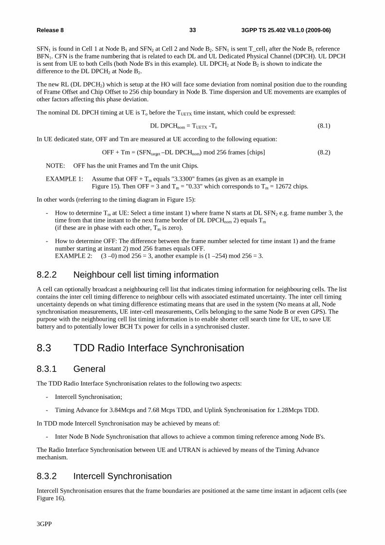
3GPP
33 Release 8 3GPP TS 25.402 V8.1.0 (2009-06)
SFN1 is found in Cell 1 at Node B1 and SFN2 at Cell 2 and Node B2. SFN1 is sent T_cell1 after the Node B1 reference BFN1. CFN is the frame numbering that is related to each DL and UL Dedicated Physical Channel (DPCH). UL DPCH is sent from UE to both Cells (both Node B's in this example). UL DPCH2 at Node B2 is shown to indicate the difference to the DL DPCH2 at Node B2.
The new RL (DL DPCH2) which is setup at the HO will face some deviation from nominal position due to the rounding of Frame Offset and Chip Offset to 256 chip boundary in Node B. Time dispersion and UE movements are examples of other factors affecting this phase deviation.
The nominal DL DPCH timing at UE is To before the TUETX time instant, which could be expressed:
DL DPCHnom = TUETX -To (8.1)
In UE dedicated state, OFF and Tm are measured at UE according to the following equation:
OFF + Tm = (SFNtarget –DL DPCHnom) mod 256 frames [chips] (8.2)
NOTE: OFF has the unit Frames and Tm the unit Chips.
EXAMPLE 1: Assume that OFF + Tm equals "3.3300" frames (as given as an example in Figure 15). Then OFF = 3 and Tm = "0.33" which corresponds to Tm = 12672 chips.
In other words (referring to the timing diagram in Figure 15):
- How to determine Tm at UE: Select a time instant 1) where frame N starts at DL SFN2 e.g. frame number 3, the time from that time instant to the next frame border of DL DPCHnom 2) equals Tm (if these are in phase with each other, Tm is zero).
- How to determine OFF: The difference between the frame number selected for time instant 1) and the frame number starting at instant 2) mod 256 frames equals OFF. EXAMPLE 2: (3 –0) mod 256 = 3, another example is (1 –254) mod 256 = 3.
8.2.2 Neighbour cell list timing information A cell can optionally broadcast a neighbouring cell list that indicates timing information for neighbouring cells. The list contains the inter cell timing difference to neighbour cells with associated estimated uncertainty. The inter cell timing uncertainty depends on what timing difference estimating means that are used in the system (No means at all, Node synchronisation measurements, UE inter-cell measurements, Cells belonging to the same Node B or even GPS). The purpose with the neighbouring cell list timing information is to enable shorter cell search time for UE, to save UE battery and to potentially lower BCH Tx power for cells in a synchronised cluster.
8.3 TDD Radio Interface Synchronisation
8.3.1 General The TDD Radio Interface Synchronisation relates to the following two aspects:
- Intercell Synchronisation;
- Timing Advance for 3.84Mcps and 7.68 Mcps TDD, and Uplink Synchronisation for 1.28Mcps TDD.
In TDD mode Intercell Synchronisation may be achieved by means of:
- Inter Node B Node Synchronisation that allows to achieve a common timing reference among Node B's.
The Radio Interface Synchronisation between UE and UTRAN is achieved by means of the Timing Advance mechanism.
8.3.2 Intercell Synchronisation Intercell Synchronisation ensures that the frame boundaries are positioned at the same time instant in adjacent cells (see Figure 16).
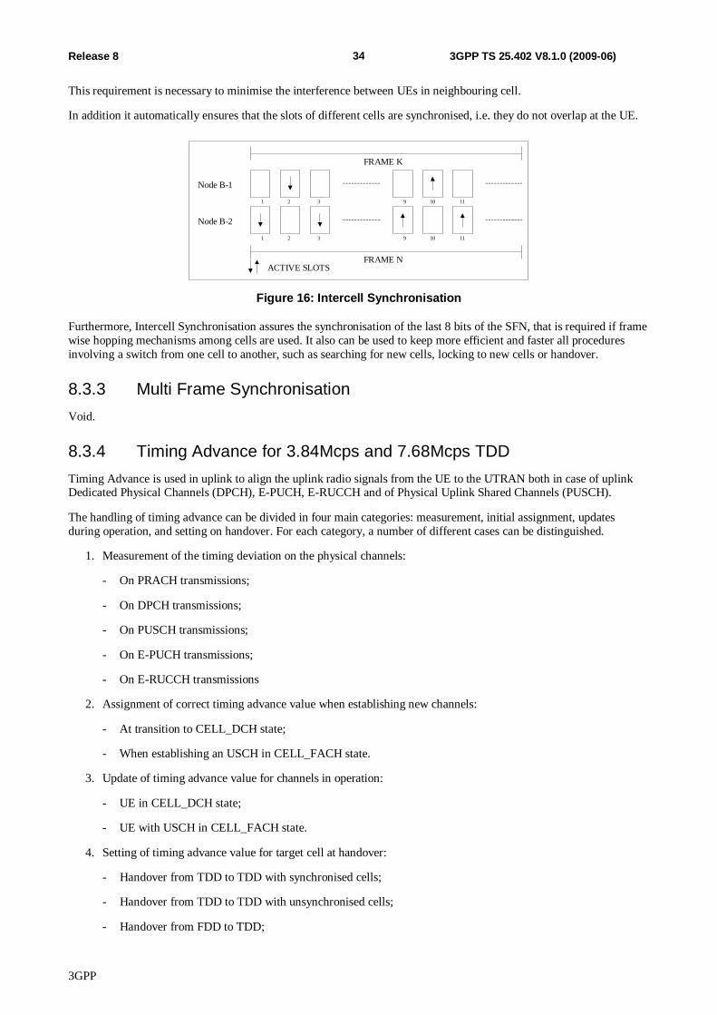
3GPP
34 Release 8 3GPP TS 25.402 V8.1.0 (2009-06)
This requirement is necessary to minimise the interference between UEs in neighbouring cell.
In addition it automatically ensures that the slots of different cells are synchronised, i.e. they do not overlap at the UE.
ACTIVE SLOTS
Node B-1
Node B-2
1 2 3 9 10 11
1 2 3 9 10 11
FRAME K
FRAME N
Figure 16: Intercell Synchronisation
Furthermore, Intercell Synchronisation assures the synchronisation of the last 8 bits of the SFN, that is required if frame wise hopping mechanisms among cells are used. It also can be used to keep more efficient and faster all procedures involving a switch from one cell to another, such as searching for new cells, locking to new cells or handover.
8.3.3 Multi Frame Synchronisation Void.
8.3.4 Timing Advance for 3.84Mcps and 7.68Mcps TDD Timing Advance is used in uplink to align the uplink radio signals from the UE to the UTRAN both in case of uplink Dedicated Physical Channels (DPCH), E-PUCH, E-RUCCH and of Physical Uplink Shared Channels (PUSCH).
The handling of timing advance can be divided in four main categories: measurement, initial assignment, updates during operation, and setting on handover. For each category, a number of different cases can be distinguished.
1. Measurement of the timing deviation on the physical channels:
- On PRACH transmissions;
- On DPCH transmissions;
- On PUSCH transmissions;
- On E-PUCH transmissions;
- On E-RUCCH transmissions
2. Assignment of correct timing advance value when establishing new channels:
- At transition to CELL_DCH state;
- When establishing an USCH in CELL_FACH state.
3. Update of timing advance value for channels in operation:
- UE in CELL_DCH state;
- UE with USCH in CELL_FACH state.
4. Setting of timing advance value for target cell at handover:
- Handover from TDD to TDD with synchronised cells;
- Handover from TDD to TDD with unsynchronised cells;
- Handover from FDD to TDD;
3GPP
35 Release 8 3GPP TS 25.402 V8.1.0 (2009-06)
- Handover from other systems to TDD.
8.3.4.1 Measurement of the timing deviation on the physical channels
Timing deviation measurements are always performed in the physical layer in Node B. These measurements have to be reported to the higher layers, where timing advance values are calculated and signalled to the UE. For this reporting, a number of different ways are foreseen, depending on the used physical channels.
PRACH: The Node B physical layer measures the timing deviation of the received PRACH signal (RX Timing Deviation) and passes this together with the transport block to the CRNC (by means of the Iub RACH Frame Protocol). In case the RACH carries a DDCH or DTCH, the measured timing deviation may be passed from DRNC to the SRNC over Iur interface (by means of the Iur RACH Frame Protocol).
NOTE: PRACH transmissions themselves are transmitted with a large guard period so they do not require timing advance.
PUSCH: The Node B physical layer measures the timing deviation of the received PUSCH signal (RX Timing Deviation) and passes this together with the transport block to the CRNC (by means of the Iub USCH Frame Protocol).
DPCH: The Node B physical layer measures the timing deviation of the received DPCH signal (RX Timing Deviation) and passes this value, if the conditions for reporting the measurement are met, to the SRNC (by means of the Iub & Iur DCH Frame Protocols – Rx Timing Deviation Frame Protocol).
E-PUCH: The Node B physical layer measures the timing deviation of the received E-PUCH signal (RX Timing Deviation) and passes this value, if conditions for reporting the measurement are met, to the SRNC (by means of the Iub & Iur DCH Frame Protocols – Rx Timing Deviation Frame Protocol).
E-RUCH: The Node B physical layer measures the timing deviation of the received E-RUCCH signal (RX Timing Deviation) and passes this value, if conditions for reporting the measurement are met, to the SRNC (by means of the Iub & Iur DCH Frame Protocols – Rx Timing Deviation Frame Protocol). When the E-RUCCH represents a Timing Advance Request message [26] the Node B calculates the timing advance and responds with a Timing Advance Response message [26].
8.3.4.2 Assignment of correct timing advance value when establishing new channels
8.3.4.2.1 Transition to CELL_DCH State
The transition to CELL_DCH state from CELL_FACH state or Idle Mode operates in the following manner:
- The SRNC checks whether an up to date timing deviation measurement is available. Such a measurement can be available from a recent RACH access (e.g. from initial access) or from a recent USCH transmission. If no up to date timing deviation measurement is available, e.g. because of lack of uplink transmissions, or during USCH over Iur, the SRNC is not informed about RX Timing Deviations, and has to trigger an uplink transmission from the UE before it can assign a DCH (for example, a RRC procedure requiring a response from the UE). The SRNC calculates the required timing advance value and saves it in the UE context in the SRNC for later use in dedicated or shared channel activation.
- The SRNC attaches the timing advance value to the channel allocation message that it signals to the UE via FACH (RRC message CONNECTION SETUP or RRC message RADIO BEARER SETUP).
- When the UE receives the channel allocation message it configures its physical layer with the given absolute timing advance value. When a timing advance command is signalled to the UE, the CFN that the new timing advance is to be applied is always signalled.
8.3.4.2.2 When establishing an USCH in CELL_FACH state
For uplink traffic using the USCH, short time allocations are sent to the UE regularly. Therefore establishing an USCH in CELL_FACH state is very similar to handling of timing advance updates during USCH operation. The UTRAN shall
3GPP
36 Release 8 3GPP TS 25.402 V8.1.0 (2009-06)
use a recent timing deviation measurement. Such a measurement shall be available from a recent USCH burst or a recent RACH access (e.g. from the RRC message PUSCH CAPACITY REQUEST).
8.3.4.2.3 When establishing E-DCH in CELL_DCH state (E-DCH/HS-DSCH operation with no UL DPCH)
The UTRAN shall use timing deviation. Such measurements shall be available in relation to recent transmissions on E-RUCCH and/or E-PUCH.
8.3.4.3 Update of timing advance value for channels in operation
8.3.4.3.1 UE in CELL_DCH state
An UE that is operating a dedicated channel (CELL_DCH state) has to update the timing advance from time to time to keep the received signal at the Node B within the required time window. Under reasonable assumptions the worst case update frequency is in the order of 8 seconds.
The timing advance update procedure operates in the following manner:
1. The SRNC determines whether a new timing advance value has to be transmitted to the UE taking into account the timing deviation measurements. The new timing advance value is calculated taking into account the UE's current timing advance value.
2. The new timing advance value and the CFN in which it is to take effect are signalled to the UE via RRC signalling on FACH or DCH (PHYSICAL CHANNEL RECONFIGURATION, TRANSPORT CHANNEL RECONFIGURATION, RADIO BEARER RECONFIGURATION or UPLINK PHYSICAL CHANNEL CONTROL are examples of possible messages on the DCCH).
3. The SRNC shall also send the updated timing advance value and the CFN in which it is to take effect to the Node B, using a user plan control message. The Node B may adjust its physical layer to take the change in uplink transmission into account.
4. When the UE receives a new timing advance value, it shall configure its physical layer so that the updated timing advance value takes effect on the given CFN specified within the RRC message. The timing advance value shall be applied to all DPCHs and, if present, to all PUSCHs.
There is no need for the UE to acknowledge the timing advance update: the Node B continually measures and reports the UE timing deviation and the UE reports the received timing advance value as part of its measurement reporting. The SRNC is thus able to detect if a timing advance update has not been received and needs to be resent.
8.3.4.3.2 UE with USCH Traffic in CELL_FACH state
If the UE uses an USCH in CELL_FACH state (no DCH), the timing advance update procedure operates in the following manner:
1. The CRNC determines whether a new timing advance value has to be transmitted to the UE taking into account when the last timing advance update was signalled. Two cases are possible:
- If the data transfer is uplink after a longer idle period then the UE has to transmit a capacity request on the RACH. The CRNC is therefore informed of any timing deviation on this RACH.
- If a new allocation follows an USCH transmission, the timing deviation is already known to the CRNC from measurements of the last uplink transmission.
2. If a Timing Advance update is needed, the CRNC includes a new timing advance value and the CFN in which it will take effect in the next USCH allocation message to the UE (PHYSICAL SHARED CHANNEL ALLOCATION).
3. The CRNC shall also send a user plane control message indicating the CFN and the updated timing advance value to the Node B so the Node B can adjust its physical layer averaging to take the change in uplink transmission into account.
3GPP
37 Release 8 3GPP TS 25.402 V8.1.0 (2009-06)
4. When the UE receives a new timing advance value, the UE shall configure its physical layer, so that the updated timing advance value takes effect on the given CFN specified within the PHYSICAL SHARED CHANNEL ALLOCATION message. The timing advance value shall be applied to all present PUSCHs.
8.3.4.4 Setting of timing advance value for target cell at handover
8.3.4.4.1 General
Since the uplink radio signals need to be adjusted only because of large enough distances between the UE and the cell transmission, certain cells will have a small enough radius that timing advance needs to not be used. In those cells the timing advance value in the UE is set to zero and UE autonomous adjustment of timing advance upon handover is disabled in the handover messages to the UE.
In these cells, where TA is not applied, the “RX Timing Deviation” measurement can be omitted if no other procedure (e.g. LCS) requires it.
8.3.4.4.2 Handover from TDD to TDD with synchronised cells
When two TDD cells are involved in handover and the two cells are sufficiently synchronised, a UE is able to measure the time offset between P-CCPCH reception of the two cells and, consequently, is able to autonomously correct its timing on handover without UTRAN assistance. However to improve the accuracy for the UE calculated timing advance, the SRNC can include an updated timing advance based on the timing deviation measured by the old cell in the messages triggering the handover in the UE. Note that this update shall apply in the old cell at the specified CFN if handover is performed on a later CFN or if the handover fails and falls back to the old cell. The UE shall use this new value as the basis for the UE autonomous update.
After a successful handover, a response message is transmitted in the new cell. In this message, if the UE autonomously updated its timing advance it shall report the calculated timing advance value, which it is using for access to the new cell. By this way, the SRNC is informed as fast as possible about the absolute timing advance value in the UE, and it can correct the timing advance immediately or in the future based on this value, if necessary.
8.3.4.4.3 Handover from FDD to TDD, Handover from other systems to TDD, or Handover from TDD to TDD with unsynchronised cells
In these cases, synchronisation between the handover cells is not possible. In the case where DPCH(s) are assigned, the new TDD cell must use a burst type with a large enough transmission window to allow the immediate transmission of data without the need of timing advance adjustment in the new cell, since timing adjustment can only be performed in these cells after the first uplink transmission. In the case where E-DCH/HS-DSCH operation is configured without a DPCH then the UE obtains timing advance in the new cell (using TA Request, see [26]) before transmitting data.
8.3.5 UL Synchronisation for 1.28Mcps TDD This section describes the details of the UL synchronisation including the establishment of UL synchronisation and maintenance of the UL synchronisation.
8.3.5.1 The establishment of uplink synchronisation
8.3.5.1.1 Preparation of uplink synchronisation by downlink synchronisation
When a UE is powered on, it first needs to establish the downlink synchronisation with the cell. Only after the UE can establish and maintain the downlink synchronisation, it can start the uplink synchronisation procedure.
8.3.5.1.2 Establishment of uplink synchronisation
Although the UE can receive the downlink synchronisation signal from the Node B, the distance to Node B is still uncertain which would lead to unsynchronised uplink transmission. Therefore, the first transmission in uplink direction is performed in Uplink Pilot Channel (UpPCH), to avoid interference in traffic time-slots.
The timing used for the SYNC_UL code are set e.g. according to the received power level of DwPCH and/or P-CCPCH.
3GPP
38 Release 8 3GPP TS 25.402 V8.1.0 (2009-06)
At the detection of the SYNC_UL sequence in the searching window, the Node B will evaluate the received power levels and timing, and reply by sending the adjustment information to UE to modify its timing and power level for next transmission and for establishment of the uplink synchronisation procedure. Within the next 4 sub-frames, the Node B will send the adjustment information to the UE (in a single subframe message in the FPACH). The uplink synchronisation procedure, normally used for a random access to the system, can also be used for the re-establishment of the uplink synchronisation when uplink is out of synchronisation.
8.3.5.2. Maintenance of uplink synchronisation
For the maintenance of the uplink synchronisation, the midamble field of each uplink burst can be used.
In each uplink time slot the midamble in each UE is different. The Node B can estimate the power level and timing shift by measuring the midamble field of each UE in the same time slot. Then, in the next available downlink time slot, the Node B will signal the Synchronisation Shift (SS) and the Power Control (PC) commands to enable the UE to properly adjust respectively its Tx timing and Tx power level.
These procedures guarantee the reliability of the uplink synchronisation. The uplink synchronisation can be checked once per 1.28Mcps TDD subframe. The step size in uplink synchronisation is configurable and re-configurable and can be adapted from 1/8 chip to 1 chip duration. The following updates for UL synchronisation are possible: 1 step up; 1 step down; no update.
For 3.84Mcps and 7.68Mcps TDD option, uplink synchronisation is mentioned in 4.3 of [16]. But the implementation method is a little different with the 1.28Mcps TDD option. For 1.28Mcps TDD option, the establishment of the UL synchronisation is done by using the UpPCH and the FPACH.
UE will select one of the set of SYNC_UL codes which can be used in the cell to establish uplink synchronisation in the access procedure. The benefit of this method is when the UE wants to do random access, the PRACH will have minimum interference to other traffic channel. Vice versa, it will also reduce the interference from traffic channels to PRACH.
9 Usage of Synchronisation Counters and Parameters to support Transport Channel and Radio Interface Synchronisation
9.1 General This subclause describes how the different synchronisation parameters and counters are computed and used in order to obtain Transport Channel (L2) and Radio Interface (L1) Synchronisation.
The parameters that need to be determined by the UE are CFN, OFF [FDD – and Tm].
The parameter that need to be determined by the UTRAN are [FDD – DOFFFDD], [TDD – DOFFTDD], Frame Offset and [FDD – Chip Offset].
Figure 17 summarises how these parameters are computed. A detailed description of the actions in each state is given in the sections 9.2 – 9.4, while some examples of corrections applied to synchronisation counters during UE state transitions are shown in section 9.5.
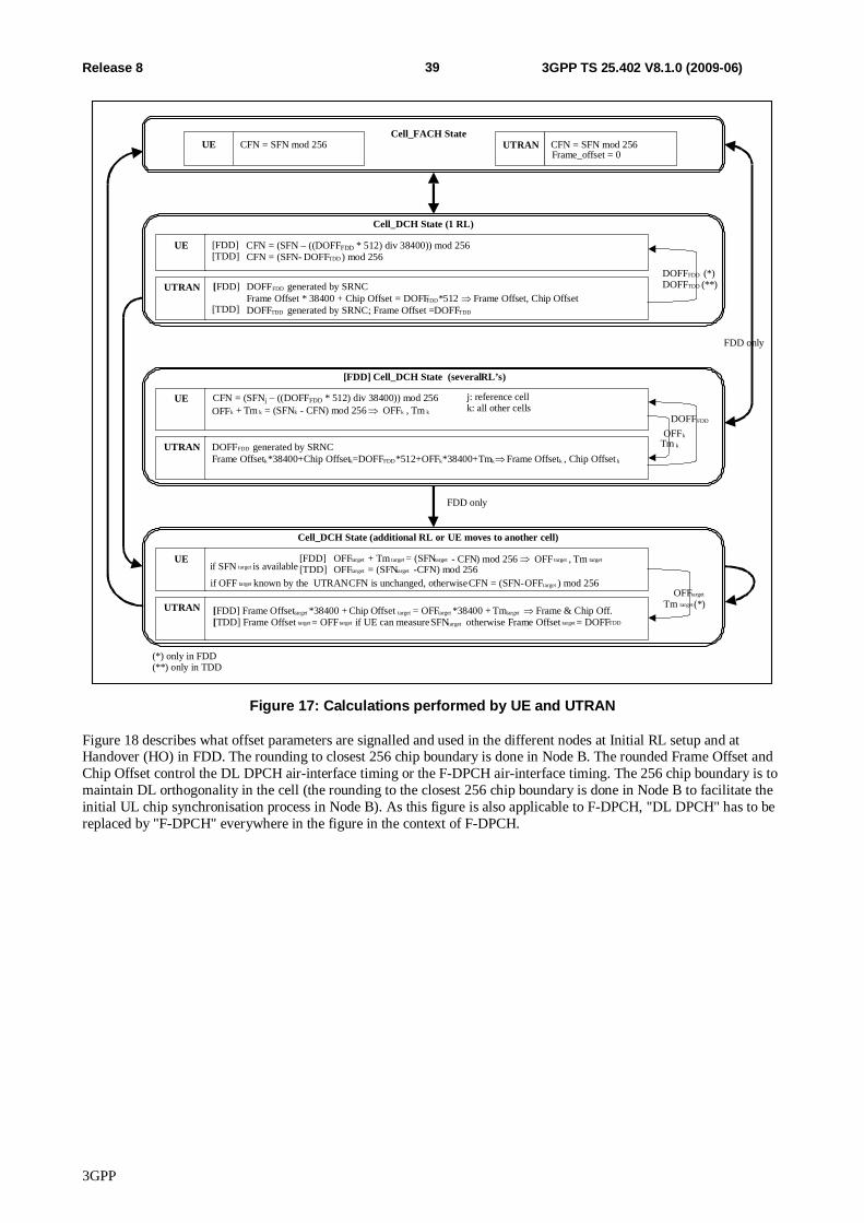
3GPP
39 Release 8 3GPP TS 25.402 V8.1.0 (2009-06)
Cell_FACH State
UE CFN = SFN mod 256 UTRAN Frame_offset = 0
Cell_DCH State (1 RL) UE [FDD]
[TDD] CFN = (SFN- DOFF TDD ) mod 256
UTRAN [ FDD] DOFF FDD generated by SRNC Frame Offset * 38400 + Chip Offset = DOFF FDD *512 Frame Offset, Chip Offset
[TDD]
[FDD] Cell_DCH State (several RL’s) UE
OFF k + Tm k = ( SFN k - CFN ) mod 256 OFF k , Tm k
UTRAN DOFF FDD generated by SRNC Frame Offset k *38400+Chip Offset k =DOFF FDD *512+OFF k *38400+Tm k Frame Offset k , Chip Offset k
FDD only
OFF k Tm k
DOFF FDD (*) DOFF TDD (**)
Cell_DCH State (additional RL or UE moves to another cell) UE [FDD] OFF target + Tm target = (SFN target - CFN ) mod 256 OFF target , Tm
target [TDD] OFF target = (SFN target -CFN) mod 256
UTRAN
(*) only in FDD (**) only in TDD
OFF target Tm target (*)
DOFF FDD
FDD only
CFN = SFN mod 256
DOFF TDD generated by SRNC; Frame Offset = DOFF TDD
[ FDD] Frame O ffset target *38400 + Chip O ffset target = OFF target *38400 + Tm target Frame & Chip Off. [ TDD] Frame Offset target = OFF target if UE can measure SFN target otherwise Frame Offset target = DOFF TDD
j: reference cell k: all other cells
if SFN target is available if OFF target known by the UTRAN CFN is unchanged, otherwise CFN = (SFN- OFF target ) mod 256
CFN = (SFN – ((DOFFFDD * 512) div 38400)) mod 256
CFN = (SFNj – ((DOFFFDD * 512) div 38400)) mod 256
Figure 17: Calculations performed by UE and UTRAN
Figure 18 describes what offset parameters are signalled and used in the different nodes at Initial RL setup and at Handover (HO) in FDD. The rounding to closest 256 chip boundary is done in Node B. The rounded Frame Offset and Chip Offset control the DL DPCH air-interface timing or the F-DPCH air-interface timing. The 256 chip boundary is to maintain DL orthogonality in the cell (the rounding to the closest 256 chip boundary is done in Node B to facilitate the initial UL chip synchronisation process in Node B). As this figure is also applicable to F-DPCH, "DL DPCH" has to be replaced by "F-DPCH" everywhere in the figure in the context of F-DPCH.
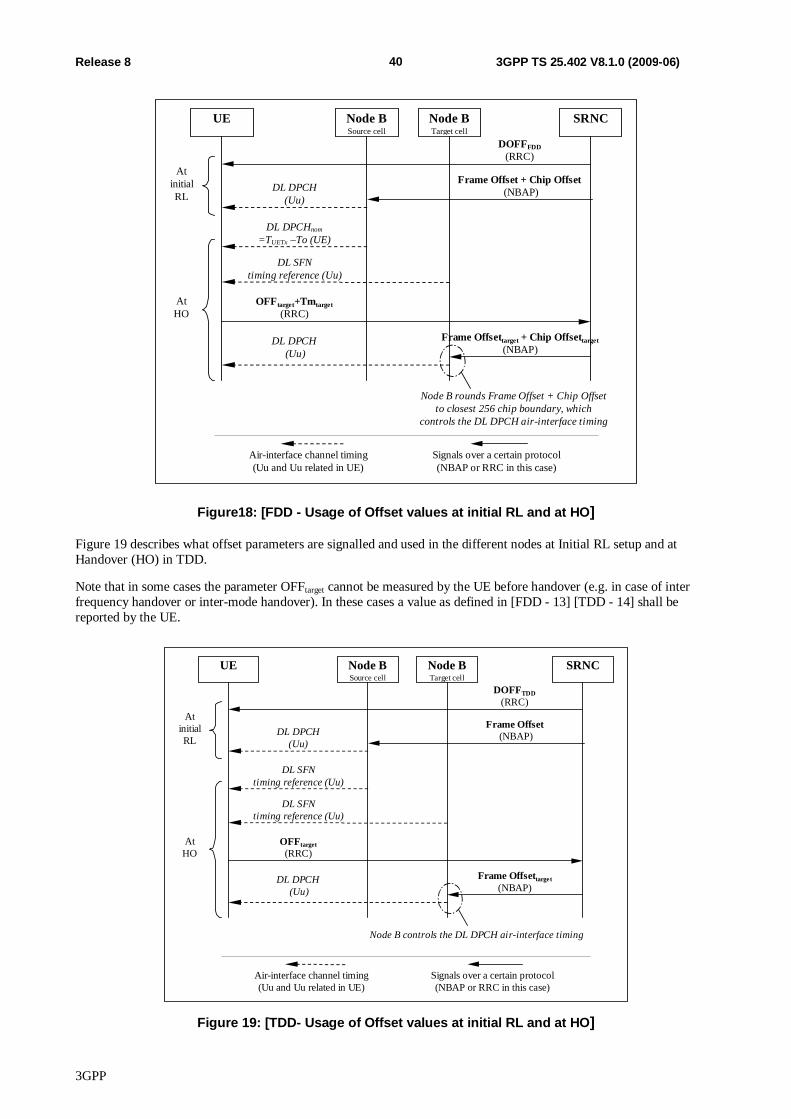
3GPP
40 Release 8 3GPP TS 25.402 V8.1.0 (2009-06)
AtHO
Frame Offset + Chip Offset (NBAP)
Node B rounds Frame Offset + Chip Offsetto closest 256 chip boundary, which
controls the DL DPCH air-interface timing
OFFtarget+Tmtarget(RRC)
Frame Offsettarget + Chip Offsettarget(NBAP)
DOFFFDD(RRC)
SRNCUE Node BSource cell
Node BTarget cell
DL DPCH(Uu)
DL SFNtiming reference (Uu)
DL DPCH (Uu)
AtinitialRL
Air-interface channel timing(Uu and Uu related in UE)
Signals over a certain protocol(NBAP or RRC in this case)
DL DPCHnom
=TUETx –To (UE)
Figure18: [FDD - Usage of Offset values at initial RL and at HO]
Figure 19 describes what offset parameters are signalled and used in the different nodes at Initial RL setup and at Handover (HO) in TDD.
Note that in some cases the parameter OFFtarget cannot be measured by the UE before handover (e.g. in case of inter frequency handover or inter-mode handover). In these cases a value as defined in [FDD - 13] [TDD - 14] shall be reported by the UE.
AtHO
Frame Offset (NBAP)
Node B controls the DL DPCH air-interface timing
OFFtarget(RRC)
Frame Offsettarget(NBAP)
SRNCUE Node BSource cell
Node BTarget cell
DL DPCH(Uu)
DL SFNtiming reference (Uu)
DL DPCH (Uu)
AtinitialRL
Air-interface channel timing(Uu and Uu related in UE)
Signals over a certain protocol(NBAP or RRC in this case)
DL SFNtiming reference (Uu)
DOFFTDD(RRC)
Figure 19: [TDD- Usage of Offset values at initial RL and at HO]
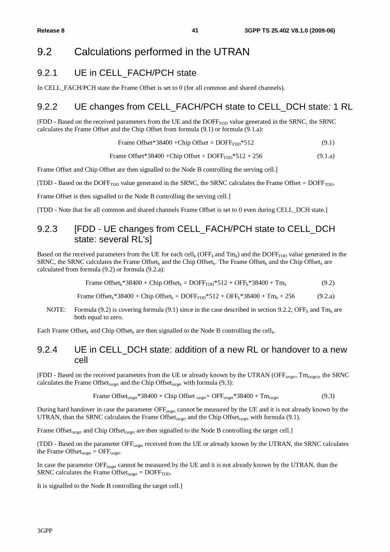
3GPP
41 Release 8 3GPP TS 25.402 V8.1.0 (2009-06)
9.2 Calculations performed in the UTRAN
9.2.1 UE in CELL_FACH/PCH state In CELL_FACH/PCH state the Frame Offset is set to 0 (for all common and shared channels).
9.2.2 UE changes from CELL_FACH/PCH state to CELL_DCH state: 1 RL [FDD - Based on the received parameters from the UE and the DOFFFDD value generated in the SRNC, the SRNC calculates the Frame Offset and the Chip Offset from formula (9.1) or formula (9.1.a):
Frame Offset*38400 +Chip Offset = DOFFFDD*512 (9.1)
Frame Offset*38400 +Chip Offset = DOFFFDD*512 + 256 (9.1.a)
Frame Offset and Chip Offset are then signalled to the Node B controlling the serving cell.]
[TDD - Based on the DOFFTDD value generated in the SRNC, the SRNC calculates the Frame Offset = DOFFTDD.
Frame Offset is then signalled to the Node B controlling the serving cell.]
[TDD - Note that for all common and shared channels Frame Offset is set to 0 even during CELL_DCH state.]
9.2.3 [FDD - UE changes from CELL_FACH/PCH state to CELL_DCH state: several RL's]
Based on the received parameters from the UE for each cellk (OFFk and Tmk) and the DOFFFDD value generated in the SRNC, the SRNC calculates the Frame Offsetk and the Chip Offsetk. The Frame Offsetk and the Chip Offsetk are calculated from formula (9.2) or formula (9.2.a):
Frame Offsetk*38400 + Chip Offsetk = DOFFFDD*512 + OFFk*38400 + Tmk (9.2)
Frame Offsetk*38400 + Chip Offsetk = DOFFFDD*512 + OFFk*38400 + Tmk + 256 (9.2.a)
NOTE: Formula (9.2) is covering formula (9.1) since in the case described in section 9.2.2, OFFk and Tmk are both equal to zero.
Each Frame Offsetk and Chip Offsetk are then signalled to the Node B controlling the cellk.
9.2.4 UE in CELL_DCH state: addition of a new RL or handover to a new cell
[FDD - Based on the received parameters from the UE or already known by the UTRAN (OFFtarget, Tmtarget), the SRNC calculates the Frame Offsettarget and the Chip Offsettarget with formula (9.3):
Frame Offsettarget*38400 + Chip Offset target= OFFtarget*38400 + Tmtarget (9.3)
During hard handover in case the parameter OFFtarget cannot be measured by the UE and it is not already known by the UTRAN, than the SRNC calculates the Frame Offsettarget and the Chip Offsettarget with formula (9.1).
Frame Offsettarget and Chip Offsettarget are then signalled to the Node B controlling the target cell.]
[TDD - Based on the parameter OFFtarget received from the UE or already known by the UTRAN, the SRNC calculates the Frame Offsettarget = OFFtarget.
In case the parameter OFFtarget cannot be measured by the UE and it is not already known by the UTRAN, than the SRNC calculates the Frame Offsettarget = DOFFTDD.
It is signalled to the Node B controlling the target cell.]
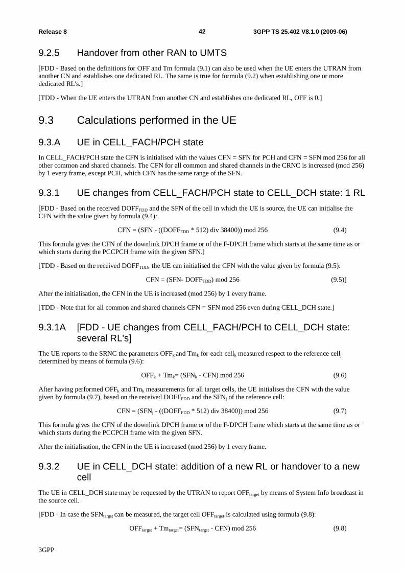
3GPP
42 Release 8 3GPP TS 25.402 V8.1.0 (2009-06)
9.2.5 Handover from other RAN to UMTS [FDD - Based on the definitions for OFF and Tm formula (9.1) can also be used when the UE enters the UTRAN from another CN and establishes one dedicated RL. The same is true for formula (9.2) when establishing one or more dedicated RL's.]
[TDD - When the UE enters the UTRAN from another CN and establishes one dedicated RL, OFF is 0.]
9.3 Calculations performed in the UE
9.3.A UE in CELL_FACH/PCH state In CELL_FACH/PCH state the CFN is initialised with the values CFN = SFN for PCH and CFN = SFN mod 256 for all other common and shared channels. The CFN for all common and shared channels in the CRNC is increased (mod 256) by 1 every frame, except PCH, which CFN has the same range of the SFN.
9.3.1 UE changes from CELL_FACH/PCH state to CELL_DCH state: 1 RL [FDD - Based on the received DOFFFDD and the SFN of the cell in which the UE is source, the UE can initialise the CFN with the value given by formula (9.4):
CFN = (SFN - ((DOFFFDD * 512) div 38400)) mod 256 (9.4)
This formula gives the CFN of the downlink DPCH frame or of the F-DPCH frame which starts at the same time as or which starts during the PCCPCH frame with the given SFN.]
[TDD - Based on the received DOFFTDD, the UE can initialised the CFN with the value given by formula (9.5):
CFN = (SFN- DOFFTDD) mod 256 (9.5)]
After the initialisation, the CFN in the UE is increased (mod 256) by 1 every frame.
[TDD - Note that for all common and shared channels CFN = SFN mod 256 even during CELL_DCH state.]
9.3.1A [FDD - UE changes from CELL_FACH/PCH to CELL_DCH state: several RL's]
The UE reports to the SRNC the parameters OFFk and Tmk for each cellk measured respect to the reference cellj determined by means of formula (9.6):
OFFk + Tmk= (SFNk - CFN) mod 256 (9.6)
After having performed OFFk and Tmk measurements for all target cells, the UE initialises the CFN with the value given by formula (9.7), based on the received DOFFFDD and the SFNj of the reference cell:
CFN = (SFNj - ((DOFFFDD * 512) div 38400)) mod 256 (9.7)
This formula gives the CFN of the downlink DPCH frame or of the F-DPCH frame which starts at the same time as or which starts during the PCCPCH frame with the given SFN.
After the initialisation, the CFN in the UE is increased (mod 256) by 1 every frame.
9.3.2 UE in CELL_DCH state: addition of a new RL or handover to a new cell
The UE in CELL_DCH state may be requested by the UTRAN to report OFFtarget by means of System Info broadcast in the source cell.
[FDD - In case the SFNtarget can be measured, the target cell OFFtarget is calculated using formula (9.8):
OFFtarget + Tmtarget= (SFNtarget - CFN) mod 256 (9.8)
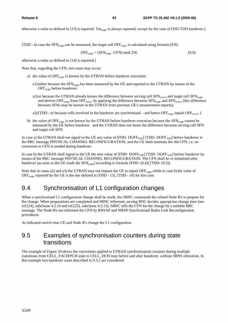
3GPP
43 Release 8 3GPP TS 25.402 V8.1.0 (2009-06)
otherwise a value as defined in [13] is reported. Tmtarget is always reported, except for the case of FDD-TDD handover.]
[TDD - In case the SFNtarget can be measured, the target cell OFFtarget is calculated using formula (9.9):
OFFtarget = (SFNtarget -CFN) mod 256 (9.9)
otherwise a value as defined in [14] is reported.]
Note that, regarding the CFN, two cases may occur:
a) the value of OFFtarget is known by the UTRAN before handover execution:
a1) either because the SFNtarget has been measured by the UE and reported to the UTRAN by means of the OFFtarget before handover;
a2) or because the UTRAN already knows the difference between serving cell SFNsource and target cell SFNtarget and derives OFFtarget from OFFsource by applying the difference between SFNtarget and SFNsource (this difference between SFNs may be known in the UTRAN from previous UE's measurement reports);
a3) [TDD - or because cells involved in the handover are synchronised – and hence OFFtarget equals OFFsource ].
b) the value of OFFtarget is not known by the UTRAN before handover execution because the SFNtarget cannot be measured by the UE before handover and the UTRAN does not know the difference between serving cell SFN and target cell SFN.
In case a) the UTRAN shall not signal to the UE any value of [FDD- DOFFFDD] [TDD- DOFFTDD] before handover in the RRC message PHYSICAL CHANNEL RECONFIGURATION, and the UE shall maintain the old CFN, i.e. no correction to CFN is needed during handover.
In case b) the UTRAN shall signal to the UE the new value of [FDD- DOFFFDD] [TDD- DOFFTDD] before handover by means of the RRC message PHYSICAL CHANNEL RECONFIGURATION. The CFN shall be re-initialised after handover (as soon as the UE reads the SFNtarget) according to formula [FDD- (9.4)] [TDD- (9.5)].
Note that in cases a2) and a3) the UTRAN may not request the UE to report OFFtarget,while in case b) the value of OFFtarget reported by the UE is the one defined in [FDD - 13], [TDD - 14] for this case.
9.4 Synchronisation of L1 configuration changes When a synchronised L1 configuration change shall be made, the SRNC commands the related Node B's to prepare for the change. When preparations are completed and SRNC informed, serving RNC decides appropriate change time (see ref.[24], subclause 4.2.14 and ref.[25], subclause 4.2.13). SRNC tells the CFN for the change by a suitable RRC message. The Node B's are informed the CFN by RNSAP and NBAP Synchronised Radio Link Reconfiguration procedures.
At indicated switch time UE and Node B's change the L1 configuration.
9.5 Examples of synchronisation counters during state transitions
The example of Figure 20 shows the corrections applied to UTRAN synchronisation counters during multiple transitions from CELL_FACH/PCH state to CELL_DCH state before and after handover, without SRNS relocation. In this example two handover cases described in 9.3.2 are considered.
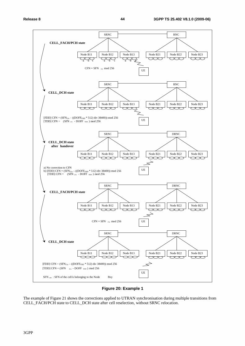
3GPP
44 Release 8 3GPP TS 25.402 V8.1.0 (2009-06)
SRNC
Node B11 Node B12 Node B13
RNC
Node B21 Node B22 Node B23
UE CFN = SFN 13c mod 256
CELL_FACH/PCH state
SRNC
Node B11 Node B12 Node B13
RNC
Node B21 Node B22 Node B23
UE [TDD] CFN = ( SFN 13c - DOFF TDD ) mod 256
CELL_DCH state
SRNC
Node B11 Node B12 Node B13
DRNC
Node B21 Node B22 Node B23
UE a) No correction to CFN [TDD] CFN = ( SFN 21a - DOFF TDD ) mod 256
CELL_DCH state after handover
SRNC
Node B11 Node B12 Node B13
DRNC
Node B21 Node B22 Node B23
UE
CELL_FACH/PCH state
SRNC
Node B11 Node B12 Node B13
DRNC
Node B21 Node B22 Node B23
CELL_DCH state
CFN = SFN 21a mod 256
[TDD] CFN = (SFN 21a - DOFF TDD ) mod 256
SFN xyk : SFN of the cell k belonging to the Node Bxy
a b c a b c a b c
[FDD] CFN = (SFN13c – ((DOFFFDD * 512) div 38400)) mod 256
b) [FDD] CFN = (SFN21a – ((DOFFFDD * 512) div 38400)) mod 256
[FDD] CFN = (SFN21a – ((DOFFFDD * 512) div 38400)) mod 256
UE
Figure 20: Example 1
The example of Figure 21 shows the corrections applied to UTRAN synchronisation during multiple transitions from CELL_FACH/PCH state to CELL_DCH state after cell reselection, without SRNC relocation.
3GPP
45 Release 8 3GPP TS 25.402 V8.1.0 (2009-06)
SRNC
Node B11 Node B12 Node B13
RNC
Node B21 Node B22 Node B23
UE CFN = SFN 13c mod 256
CELL_FACH/PCH state
SRNC
Node B11 Node B12 Node B13
CRNC
Node B21 Node B22 Node B23
UE
CELL_FACH/PCH state after cell
reselection
SRNC
Node B11 Node B12 Node B13
DRNC
Node B21 Node B22 Node B23
UE
CELL_DCH state
SRNC
Node B11 Node B12 Node B13
DRNC
Node B21 Node B22 Node B23
UE
CELL_FACH/PCH state
CFN = SFN 21a mod 256
CFN = SFN 21a mod 256
[TDD] CFN = SFN 21a mod 256
SFN xyk : SFN of the cell k belonging to the Node Bxy
[FDD] CFN = (SFN21a – ((DOFFFDD * 512) div 38400)) mod 256
Figure 21: Example 2
The example of Figure 22 shows the corrections applied to UTRAN synchronisation counters during multiple transitions from CELL_FACH/PCH state to CELL_DCH state before and after handover and SRNS relocation (without UE involvement). In this example two handover cases described in 9.3.2 are considered.
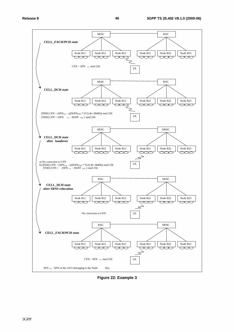
3GPP
46 Release 8 3GPP TS 25.402 V8.1.0 (2009-06)
SRNC
Node B11 Node B12 Node B13
RNC
Node B21 Node B22 Node B23
UE CFN = SFN 13c mod 256
CELL_FACH/PCH state
SRNC
Node B11 Node B12 Node B13
RNC
Node B21 Node B22 Node B23
UE [TDD] CFN = (SFN 13c - DOFF TDD ) mod 256
CELL_DCH state
SRNC
Node B11 Node B12 Node B13
DRNC
Node B21 Node B22 Node B23
UE
CELL_DCH state after handover
RNC
Node B11 Node B12 Node B13
SRNC
Node B21 Node B22 Node B23
UE
CELL_DCH state after SRNS relocation
RNC
Node B11 Node B12 Node B13
SRNC
Node B21 Node B22 Node B23
UE
CELL_FACH/PCH state
CFN = SFN 21a mod 256
SFN xyk : SFN of the cell k belonging to the Node Bxy
No correction to CFN
a) No correction to CFN [TDD] CFN = ( SFN 21a - DOFF TDD ) mod 256
[FDD] CFN = (SFN13c – ((DOFFFDD * 512) div 38400)) mod 256
b) [FDD] CFN = (SFN21a – ((DOFFFDD * 512) div 38400)) mod 256
Figure 22: Example 3
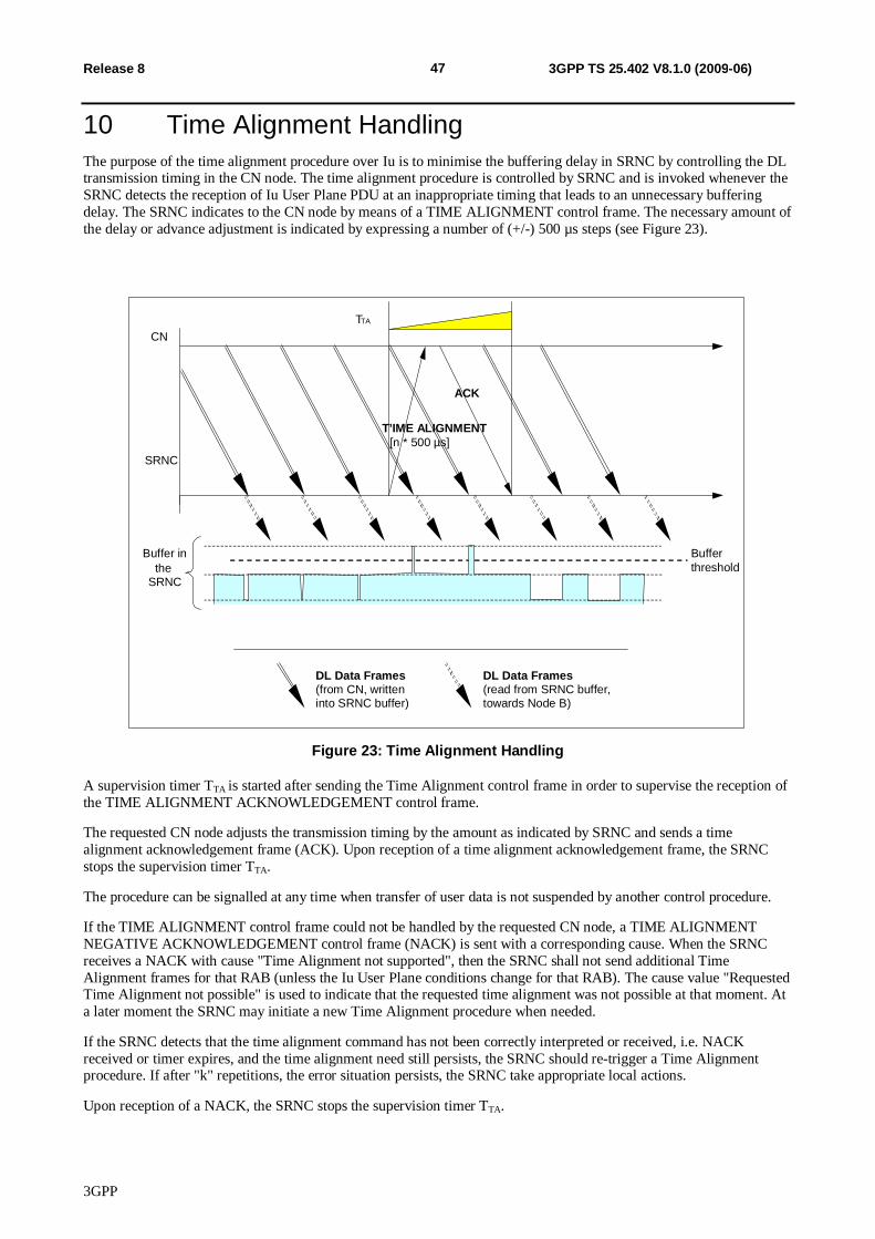
3GPP
47 Release 8 3GPP TS 25.402 V8.1.0 (2009-06)
10 Time Alignment Handling The purpose of the time alignment procedure over Iu is to minimise the buffering delay in SRNC by controlling the DL transmission timing in the CN node. The time alignment procedure is controlled by SRNC and is invoked whenever the SRNC detects the reception of Iu User Plane PDU at an inappropriate timing that leads to an unnecessary buffering delay. The SRNC indicates to the CN node by means of a TIME ALIGNMENT control frame. The necessary amount of the delay or advance adjustment is indicated by expressing a number of (+/-) 500 µs steps (see Figure 23).
T TA
CN
SRNC
DL Data Frames (from CN, written into SRNC buffer)
T’IME ALIGNMENT [n * 500 µs]
ACK
Buffer in the
SRNC
Buffer threshold
DL Data Frames (read from SRNC buffer, towards Node B)
Figure 23: Time Alignment Handling
A supervision timer TTA is started after sending the Time Alignment control frame in order to supervise the reception of the TIME ALIGNMENT ACKNOWLEDGEMENT control frame.
The requested CN node adjusts the transmission timing by the amount as indicated by SRNC and sends a time alignment acknowledgement frame (ACK). Upon reception of a time alignment acknowledgement frame, the SRNC stops the supervision timer TTA.
The procedure can be signalled at any time when transfer of user data is not suspended by another control procedure.
If the TIME ALIGNMENT control frame could not be handled by the requested CN node, a TIME ALIGNMENT NEGATIVE ACKNOWLEDGEMENT control frame (NACK) is sent with a corresponding cause. When the SRNC receives a NACK with cause "Time Alignment not supported", then the SRNC shall not send additional Time Alignment frames for that RAB (unless the Iu User Plane conditions change for that RAB). The cause value "Requested Time Alignment not possible" is used to indicate that the requested time alignment was not possible at that moment. At a later moment the SRNC may initiate a new Time Alignment procedure when needed.
If the SRNC detects that the time alignment command has not been correctly interpreted or received, i.e. NACK received or timer expires, and the time alignment need still persists, the SRNC should re-trigger a Time Alignment procedure. If after "k" repetitions, the error situation persists, the SRNC take appropriate local actions.
Upon reception of a NACK, the SRNC stops the supervision timer TTA.
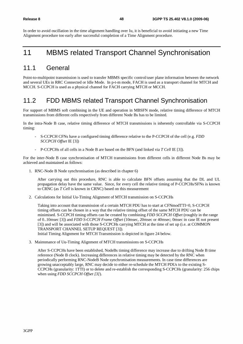
3GPP
48 Release 8 3GPP TS 25.402 V8.1.0 (2009-06)
In order to avoid oscillation in the time alignment handling over Iu, it is beneficial to avoid initiating a new Time Alignment procedure too early after successful completion of a Time Alignment procedure.
11 MBMS related Transport Channel Synchronisation
11.1 General Point-to-multipoint transmission is used to transfer MBMS specific control/user plane information between the network and several UEs in RRC Connected or Idle Mode. In p-t-m mode, FACH is used as a transport channel for MTCH and MCCH. S-CCPCH is used as a physical channel for FACH carrying MTCH or MCCH.
11.2 FDD MBMS related Transport Channel Synchronisation For support of MBMS soft combining in the UE and operation in MBSFN mode, relative timing difference of MTCH transmissions from different cells respectively from different Node Bs has to be limited.
In the intra-Node B case, relative timing difference of MTCH transmissions is inherently controllable via S-CCPCH timing:
- S-CCPCH CFNs have a configured timing difference relative to the P-CCPCH of the cell (e.g. FDD SCCPCH Offset IE [3])
- P-CCPCHs of all cells in a Node B are based on the BFN (and linked via T Cell IE [3]).
For the inter-Node B case synchronisation of MTCH transmissions from different cells in different Node Bs may be achieved and maintained as follows:
1. RNC-Node B Node synchronisation (as described in chapter 6)
After carrying out this procedure, RNC is able to calculate BFN offsets assuming that the DL and UL propagation delay have the same value. Since, for every cell the relative timing of P-CCPCHs/SFNs is known to CRNC (as T Cell is known in CRNC) based on this measurement
2. Calculations for Initial Uu-Timing Alignment of MTCH transmission on S-CCPCHs
Taking into account that transmission of a certain MTCH PDU has to start at CFNmodTTI=0, S-CCPCH timing offsets can be chosen in a way that the relative timing offset of the same MTCH PDU can be minimised. S-CCPCH timing offsets can be created by combining FDD SCCPCH Offset (roughly in the range of 0..10msec [3]) and FDD S-CCPCH Frame Offset (10msec, 20msec or 40msec; 0msec in case IE not present [3]) and will be associated with those S-CCPCHs carrying MTCH at the time of set up (i.e. at COMMON TRANSPORT CHANNEL SETUP REQUEST [3]). Initial Timing Alignment for MTCH Transmission is depicted in figure 24 below.
3. Maintenance of Uu-Timing Alignment of MTCH transmissions on S-CCPCHs
After S-CCPCHs have been established, NodeBs timing difference may increase due to drifting Node B time reference (Node B clock). Increasing differences in relative timing may be detected by the RNC when periodically performing RNC-NodeB Node synchronisation measurements. In case time differences are growing unacceptably large, RNC may decide to either re-schedule the MTCH PDUs to the existing S-CCPCHs (granularity: 1TTI) or to delete and re-establish the corresponding S-CCPCHs (granularity: 256 chips when using FDD SCCPCH Offset [3]).
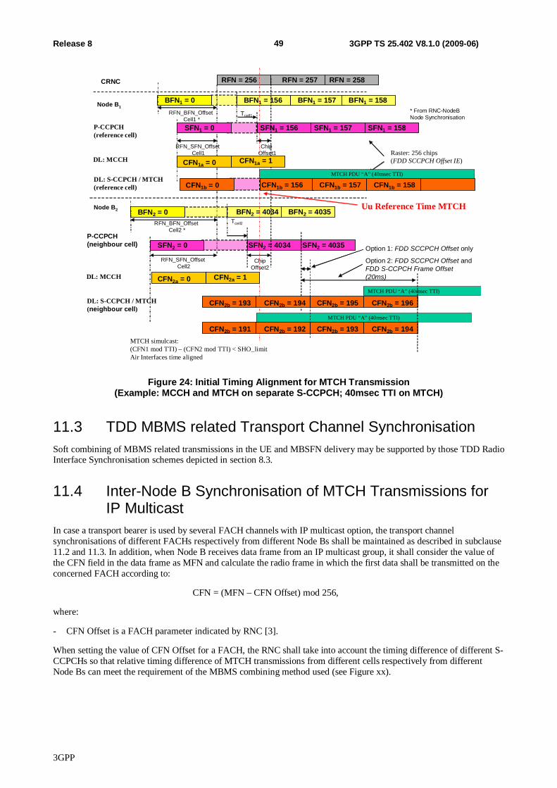
3GPP
49 Release 8 3GPP TS 25.402 V8.1.0 (2009-06)
Node B1
P-CCPCH (reference cell)
Node B2
P-CCPCH (neighbour cell)
BFN2 = 4034
SFN2 = 4034
Tcell2
BFN2 = 4035
SFN2 = 4035
DL: S-CCPCH / MTCH (reference cell)
DL: S-CCPCH / MTCH (neighbour cell)
BFN1 = 156
SFN1 = 156
Tcell1
BFN1 = 157
SFN1 = 157 SFN1 = 158
RFN = 256 RFN = 257 RFN = 258
BFN1 = 158
RFN_SFN_OffsetCell1
Chip Offset1
ChipOffset2
MTCH simulcast:(CFN1 mod TTI) – (CFN2 mod TTI) < SHO_limitAir Interfaces time aligned
CFN2b = 195 CFN2b = 196
Option 2: FDD SCCPCH Offset and FDD S-CCPCH Frame Offset(20ms)
CRNC
RFN_SFN_OffsetCell2
SFN1 = 0
SFN2 = 0
RFN_BFN_OffsetCell1 *
* From RNC-NodeBNode Synchronisation
BFN1 = 0
BFN2 = 0RFN_BFN_Offset
Cell2 *
Raster: 256 chips(FDD SCCPCH Offset IE)CFN1a = 0 CFN1a = 1DL: MCCH
CFN2a = 0 CFN2a = 1DL: MCCH
Uu Reference Time MTCH
CFN1b = 156CFN1b = 0 CFN1b = 157 CFN1b = 158
CFN2b = 193 CFN2b = 194
CFN2b = 193 CFN2b = 194CFN2b = 191 CFN2b = 192
Option 1: FDD SCCPCH Offset only
MTCH PDU “A” (40msec TTI)
MTCH PDU “A” (40msec TTI)
MTCH PDU “A” (40msec TTI)
Figure 24: Initial Timing Alignment for MTCH Transmission (Example: MCCH and MTCH on separate S-CCPCH; 40msec TTI on MTCH)
11.3 TDD MBMS related Transport Channel Synchronisation Soft combining of MBMS related transmissions in the UE and MBSFN delivery may be supported by those TDD Radio Interface Synchronisation schemes depicted in section 8.3.
11.4 Inter-Node B Synchronisation of MTCH Transmissions for IP Multicast
In case a transport bearer is used by several FACH channels with IP multicast option, the transport channel synchronisations of different FACHs respectively from different Node Bs shall be maintained as described in subclause 11.2 and 11.3. In addition, when Node B receives data frame from an IP multicast group, it shall consider the value of the CFN field in the data frame as MFN and calculate the radio frame in which the first data shall be transmitted on the concerned FACH according to:
CFN = (MFN – CFN Offset) mod 256,
where:
- CFN Offset is a FACH parameter indicated by RNC [3].
When setting the value of CFN Offset for a FACH, the RNC shall take into account the timing difference of different S-CCPCHs so that relative timing difference of MTCH transmissions from different cells respectively from different Node Bs can meet the requirement of the MBMS combining method used (see Figure xx).
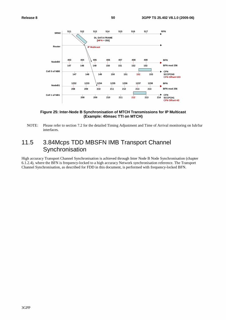
3GPP
50 Release 8 3GPP TS 25.402 V8.1.0 (2009-06)
SRNC
NodeB0
CFNSCCPCH0CFN Offset=103
RFN514 515 516 517511 512 513
149 150 151 152 153147 148
DL DATA FRAME[MFN = 255]
210 211 212 213 214208 209CFN SCCPCH1CFN Offset=43
BFN
BFN mod 256
Cell 0 of NB0
Cell 1 of NB1
405 406 407 408 409403 404
Router
NodeB11234 1235 1236 1237 12381232 1233 BFN
BFN mod 256
IP Multicast
149 150 151 152 153147 148
210 211 212 213 214208 209
Figure 25: Inter-Node B Synchronisation of MTCH Transmissions for IP Multicast (Example: 40msec TTI on MTCH)
NOTE: Please refer to section 7.2 for the detailed Timing Adjustment and Time of Arrival monitoring on Iub/Iur interfaces.
11.5 3.84Mcps TDD MBSFN IMB Transport Channel Synchronisation
High accuracy Transport Channel Synchronisation is achieved through Inter Node B Node Synchronisation (chapter 6.1.2.4), where the BFN is frequency-locked to a high accuracy Network synchronisation reference. The Transport Channel Synchronisation, as described for FDD in this document, is performed with frequency-locked BFN.
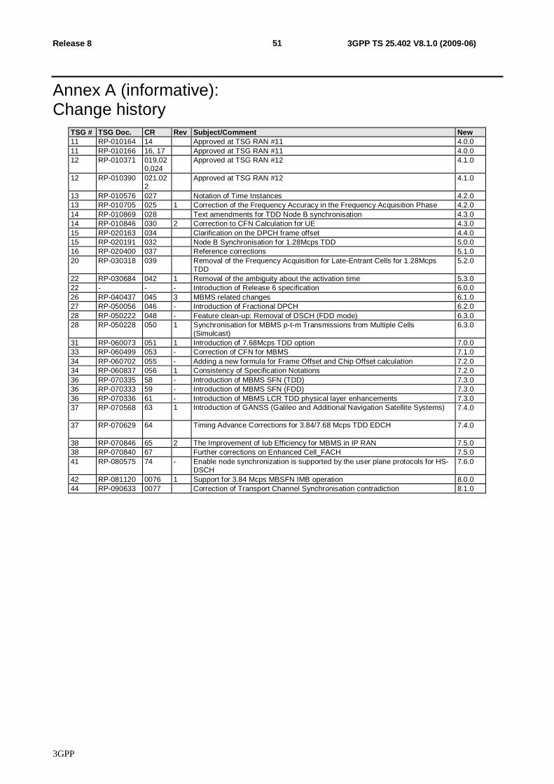
3GPP
51 Release 8 3GPP TS 25.402 V8.1.0 (2009-06)
Annex A (informative): Change history
TSG # TSG Doc. CR Rev Subject/Comment New 11 RP-010164 14 Approved at TSG RAN #11 4.0.0 11 RP-010166 16, 17 Approved at TSG RAN #11 4.0.0 12 RP-010371 019,02
0,024 Approved at TSG RAN #12 4.1.0
12 RP-010390 021.022
Approved at TSG RAN #12 4.1.0
13 RP-010576 027 Notation of Time Instances 4.2.0 13 RP-010705 025 1 Correction of the Frequency Accuracy in the Frequency Acquisition Phase 4.2.0 14 RP-010869 028 Text amendments for TDD Node B synchronisation 4.3.0 14 RP-010846 030 2 Correction to CFN Calculation for UE 4.3.0 15 RP-020163 034 Clarification on the DPCH frame offset 4.4.0 15 RP-020191 032 Node B Synchronisation for 1.28Mcps TDD 5.0.0 16 RP-020400 037 Reference corrections 5.1.0 20 RP-030318 039 Removal of the Frequency Acquisition for Late-Entrant Cells for 1.28Mcps
TDD 5.2.0
22 RP-030684 042 1 Removal of the ambiguity about the activation time 5.3.0 22 - - - Introduction of Release 6 specification 6.0.0 26 RP-040437 045 3 MBMS related changes 6.1.0 27 RP-050056 046 - Introduction of Fractional DPCH 6.2.0 28 RP-050222 048 - Feature clean-up: Removal of DSCH (FDD mode) 6.3.0 28 RP-050228 050 1 Synchronisation for MBMS p-t-m Transmissions from Multiple Cells
(Simulcast) 6.3.0
31 RP-060073 051 1 Introduction of 7.68Mcps TDD option 7.0.0 33 RP-060499 053 - Correction of CFN for MBMS 7.1.0 34 RP-060702 055 - Adding a new formula for Frame Offset and Chip Offset calculation 7.2.0 34 RP-060837 056 1 Consistency of Specification Notations 7.2.0 36 RP-070335 58 - Introduction of MBMS SFN (TDD) 7.3.0 36 RP-070333 59 - Introduction of MBMS SFN (FDD) 7.3.0 36 RP-070336 61 - Introduction of MBMS LCR TDD physical layer enhancements 7.3.0 37 RP-070568 63 1 Introduction of GANSS (Galileo and Additional Navigation Satellite Systems) 7.4.0
37 RP-070629 64 Timing Advance Corrections for 3.84/7.68 Mcps TDD EDCH 7.4.0
38 RP-070846 65 2 The Improvement of Iub Efficiency for MBMS in IP RAN 7.5.0 38 RP-070840 67 Further corrections on Enhanced Cell_FACH 7.5.0 41 RP-080575 74 - Enable node synchronization is supported by the user plane protocols for HS-
DSCH 7.6.0
42 RP-081120 0076 1 Support for 3.84 Mcps MBSFN IMB operation 8.0.0 44 RP-090633 0077 Correction of Transport Channel Synchronisation contradiction 8.1.0