Embed Size (px)
Citation preview
3GPP TS 26.193 V6.0.0 (2004-12)Technical Specification
3rd Generation Partnership Project;Technical Specification Group Services and System Aspects;
Speech codec speech processing functions;Adaptive Multi-Rate - Wideband (AMR-WB) speech codec;
Source controlled rate operation(Release 6)
GLOBAL SYSTEM FOR MOBILE COMMUNICATIONS
R
The present document has been developed within the 3rd Generation Partnership Project (3GPP TM) and may be further elaborated for the purposes of 3GPP. The present document has not been subject to any approval process by the 3GPP Organizational Partners and shall not be implemented. This Specification is provided for future development work within 3GPP only. The Organizational Partners accept no liability for any use of this Specification.Specifications and reports for implementation of the 3GPP TM system should be obtained via the 3GPP Organizational Partners' Publications Offices.

3GPP
3GPP TS 26.193 V6.0.0 (2004-12)2Release 6
Keywords UMTS, GSM, CODEC
3GPP
Postal address
3GPP support office address 650 Route des Lucioles - Sophia Antipolis
Valbonne - FRANCE Tel.: +33 4 92 94 42 00 Fax: +33 4 93 65 47 16
Internet http://www.3gpp.org
Copyright Notification
No part may be reproduced except as authorized by written permission. The copyright and the foregoing restriction extend to reproduction in all media.
© 2004, 3GPP Organizational Partners (ARIB, ATIS, CCSA, ETSI, TTA,TTC).
All rights reserved.

3GPP
3GPP TS 26.193 V6.0.0 (2004-12)3Release 6
Contents Foreword ............................................................................................................................................................4 1 Scope ........................................................................................................................................................5 2 Normative references ...............................................................................................................................5 3 Definitions, symbols and abbreviations ...................................................................................................5 3.1 Definitions................................................................................................................................................................... 5 3.2 Symbols....................................................................................................................................................................... 6 3.3 Abbreviations.............................................................................................................................................................. 6 4 General .....................................................................................................................................................6 4.1 General organisation ................................................................................................................................................... 6 5 AMR-WB SCR operation ........................................................................................................................7 5.1 Transmit (TX) side...................................................................................................................................................... 7 5.1.1 General operation .................................................................................................................................................. 7 5.1.2 Functions of the TX SCR handler ........................................................................................................................ 8 5.1.2.1 AMR-WB SCR Timing procedures.......................................................................................................................... 8 5.1.3 The TX part of the AN.......................................................................................................................................... 9 5.2 Receive (RX) side..................................................................................................................................................... 10 5.2.1 General operation ................................................................................................................................................ 10 5.2.3 Demands on the RX SCR handler ...................................................................................................................... 11 5.3 AMR-WB SID Information format .......................................................................................................................... 11
Annex A: (normative) AMR-WB DTX handler for the GSM system .......................................................12 A.1 Scope ......................................................................................................................................................12 A.2 References ..............................................................................................................................................12 A.3 Definitions, symbols and abbreviations .................................................................................................13 A.3.1 Definitions........................................................................................................................................................... 13 A.3.2 Symbols ............................................................................................................................................................... 13 A.3.3 Abbreviations ...................................................................................................................................................... 14 A.4 General ...................................................................................................................................................14 A.4.1 General organisation ........................................................................................................................................... 14 A.5 Transmit (TX) side .................................................................................................................................15 A.5.1 General operation ................................................................................................................................................ 15 A.5.1.1 Functions of the TX DTX handler...................................................................................................................... 16 A.5.1.2 Functions of the TX Radio Subsystem............................................................................................................... 17 A.5.1.2.1 Functions of the TX Radio Subsystem for TCH/WFS................................................................................. 17 A.5.1.2.2 Functions of the Downlink TX Radio Subsystem for TFO.......................................................................... 18 A.5.1.2.4 Functions of the TX Radio Subsystem for RATSCCH................................................................................ 18 A.6 Receive (RX) side ..................................................................................................................................19 A.6.1 General operation ................................................................................................................................................ 19 A.6.1.1 Functions of the RX radio subsystem................................................................................................................. 19 A.6.1.2 Functions of the RX DTX handler...................................................................................................................... 20
Annex B: (informative) Change history .......................................................................................................21

3GPP
3GPP TS 26.193 V6.0.0 (2004-12)4Release 6
Foreword This Technical Specification has been produced by the 3GPP.
The present document describes the operation of the Adaptive Multi Rate Wideband speech codec during Source Controlled Rate (SCR) operation within the 3GPP system.
The contents of the present document are subject to continuing work within the TSG and may change following formal TSG approval. Should the TSG modify the contents of this TS, it will be re-released by the TSG with an identifying change of release date and an increase in version number as follows:
Version x.y.z
where:
x the first digit:
1 presented to TSG for information;
2 presented to TSG for approval;
3 or greater indicates TSG approved document under change control.
y the second digit is incremented for all changes of substance, i.e. technical enhancements, corrections, updates, etc.
z the third digit is incremented when editorial only changes have been incorporated in the specification;
3GPP
3GPP TS 26.193 V6.0.0 (2004-12)5Release 6
1 Scope This document describes the Source Controlled Rate (SCR) operation of the Adaptive Multi-Rate Wideband speech Codec. The implementation of this SCR operation is mandatory in all UMTS equipment implementing the Adaptive Multi-Rate Wideband speech Codec.
The description is structured according to the block diagram in Figure 1. This structure of distributing the various functions between system entities is not mandatory for implementation, as long as the operation on the speech decoder output remains the same.
Annex A describes the Discontinuous Transmission (DTX) operation of the Adaptive Multi-Rate Wideband speech Codec in Codec Type FR_AMR-WB for the GSM system.
2 Normative references This document incorporates by dated and undated reference, provisions from other publications. These normative references are cited at the appropriate places in the text and the publications are listed hereafter. For dated references, subsequent amendments to or revisions of any of these publications apply to this document only when incorporated in it by amendment or revision. For undated references, the latest edition of the publication referred to applies.
[1] 3GPP TS 26.171 : "AMR Wideband Speech Codec; General description".
[2] 3GPP TS 26.173 : "AMR Wideband Speech Codec; ANSI-C code".
[3] 3GPP TS 26.174 : "AMR Wideband Speech Codec; Test sequences".
[4] 3GPP TS 26.190 : "AMR Wideband Speech Codec; Transcoding functions".
[5] 3GPP TS 26.191 : "AMR Wideband Speech Codec; Error concealment of lost frames".
[6] 3GPP TS 26.192 : "AMR Wideband Speech Codec; Comfort noise aspects".
[7] 3GPP TS 26.194 : "AMR Wideband Speech Codec; Voice Activity Detector (VAD)".
[8] 3GPP TS 26.201 : “AMR Wideband Speech Codec; Frame structure".
3 Definitions, symbols and abbreviations
3.1 Definitions For the purpose of this document, the following definitions apply.
frame: Time interval of 20 ms, corresponding to the time segmentation of the Adaptive Multi-Rate Wideband speech Codec, also used as a short term for a traffic frame.
traffic frame: Block of 132..477 information bits transmitted on the speech traffic channels.
SID frame: Frame that conveys information about the acoustic background noise.
speech frame: Traffic frame that has been classified as SPEECH_GOOD, SPEECH_BAD or SPEECH_LOST frame.
VAD flag: Boolean flag, generated by the VAD algorithm indicating the presence ("1") or the absence ("0") of a speech frame.
RX_TYPE: classifies the received frame.
TX_TYPE: classifies the frame to be transmitted.
3GPP
3GPP TS 26.193 V6.0.0 (2004-12)6Release 6
hangover period: A period of frames added at the end of a speech burst in which VAD flag ="0" and TX_TYPE is ="SPEECH_GOOD", this period provides the encoder with an extra window to derive the Comfort Noise parameters .
3.2 Symbols For the purpose of this document, the following symbols apply.
Nelapsed Number of elapsed frames since the last updated SID frame.
3.3 Abbreviations For the purpose of this document , the following abbreviations apply.
AN Access Network SCR Source Controlled Rate operation TS Telecommunication Standard, Technical Specification GSM Global System for Mobile Telecommunication UE User Equipment RAN Radio Access Network RX Receive SID Silence Descriptor TX Transmit VAD Voice Activity Detector
4 General Source Controlled Rate operation (SCR) is a mechanism for the AMR Wideband Speech Codec, which allows to encode the input signal at a lower average rate by taking speech inactivity into account. The SCR scheme may be used for the following purposes:
-to save power in the User Equipment;
-to reduce the overall interference and load in the networks.
SCR in the transmitting path (uplink) shall be in operation in UEs, if commanded so by the network. The UE shall handle SCR in the receiving path (downlink) at any time, regardless, whether SCR in the transmitting path is commanded or not.
4.1 General organisation The default SCR mechanism described in this document requires the following functions:
-a Voice Activity Detector (VAD) on the transmit (TX) side;
-evaluation of the background acoustic noise on the transmit (TX) side, in order to transmit characteristic parameters to the receive (RX) side;
-generation on the receive (RX) side of a similar noise, called comfort noise, during periods where the transmission is switched off.
The Voice Activity Detector (VAD) is defined in [7] and the comfort noise functions in [6]. Both are based partly on the speech Codec and its internal variables, defined in [4].
In addition to these functions, if the parameters arriving at the RX side are detected to be seriously corrupted by errors, the speech or comfort noise must be generated from substituted data in order to avoid seriously annoying effects for the listener. These functions are defined in [5].
An overall description of the speech processing parts can be found in [1]. An overview of one link SCR operation is shown in Figure 1.

3GPP
3GPP TS 26.193 V6.0.0 (2004-12)7Release 6
RX_TYPE
Mode Indication
Information bits
TX SCR handler
SpeechEncoder
VoiceActivityDetector
Comfort NoiseParameter
Computation
“Network”
Informationpacketing,
transport andclassification
Information bits
Mode Indication
TX_TYPE
RX SCR handler
SpeechDecoder
ErrorConcealment
ComfortNoise
Generation
Figure 1: Block diagram of one link SCR operation
5 AMR-WB SCR operation
5.1 Transmit (TX) side A block diagram of the transmit side SCR functions is shown in Figure 2.
TX SCR handler
SpeechEncoder
VoiceActivity
Detector
Comfort NoiseParameter
Computation
TX Access Network
TX ofinformation
Information bits
Mode Indication
TX_TYPE
TS26.201
Information bits
Frame Type
FQI
Framing
Figure 2: Block diagram of SCR functions at the TX side
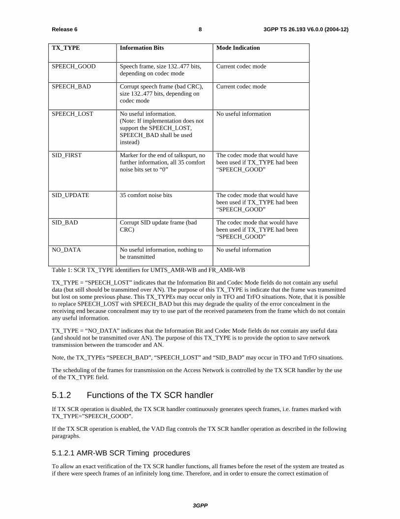
5.1.1 General operation The TX SCR handler passes traffic frames, individually marked by TX_TYPE, to the Framing unit. Each frame consists of bit fields containing the information bits, the codec mode indication, and the TX_TYPE. TX_TYPE shall be used to specify the contents of the frame. The table below provides an overview of the different TX_TYPEs used and explains the required contents in the information bit and the mode indication bit fields.
3GPP
3GPP TS 26.193 V6.0.0 (2004-12)8Release 6
TX_TYPE Information Bits Mode Indication
SPEECH_GOOD Speech frame, size 132..477 bits, depending on codec mode
Current codec mode
SPEECH_BAD Corrupt speech frame (bad CRC), size 132..477 bits, depending on codec mode
Current codec mode
SPEECH_LOST No useful information. (Note: If implementation does not support the SPEECH_LOST, SPEECH_BAD shall be used instead)
No useful information
SID_FIRST
Marker for the end of talkspurt, no further information, all 35 comfort noise bits set to “0”
The codec mode that would have been used if TX_TYPE had been “SPEECH_GOOD”
SID_UPDATE
35 comfort noise bits The codec mode that would have been used if TX_TYPE had been “SPEECH_GOOD”
SID_BAD Corrupt SID update frame (bad CRC)
The codec mode that would have been used if TX_TYPE had been “SPEECH_GOOD”
NO_DATA No useful information, nothing to be transmitted
No useful information
Table 1: SCR TX_TYPE identifiers for UMTS_AMR-WB and FR_AMR-WB
TX_TYPE = “SPEECH_LOST” indicates that the Information Bit and Codec Mode fields do not contain any useful data (but still should be transmitted over AN). The purpose of this TX_TYPE is indicate that the frame was transmitted but lost on some previous phase. This TX_TYPEs may occur only in TFO and TrFO situations. Note, that it is possible to replace SPEECH_LOST with SPEECH_BAD but this may degrade the quality of the error concealment in the receiving end because concealment may try to use part of the received parameters from the frame which do not contain any useful information.
TX_TYPE = “NO_DATA” indicates that the Information Bit and Codec Mode fields do not contain any useful data (and should not be transmitted over AN). The purpose of this TX_TYPE is to provide the option to save network transmission between the transcoder and AN.
Note, the TX_TYPEs “SPEECH_BAD”, “SPEECH_LOST” and “SID_BAD” may occur in TFO and TrFO situations.
The scheduling of the frames for transmission on the Access Network is controlled by the TX SCR handler by the use of the TX_TYPE field.
5.1.2 Functions of the TX SCR handler If TX SCR operation is disabled, the TX SCR handler continuously generates speech frames, i.e. frames marked with TX_TYPE=”SPEECH_GOOD”.
If the TX SCR operation is enabled, the VAD flag controls the TX SCR handler operation as described in the following paragraphs.
5.1.2.1 AMR-WB SCR Timing procedures
To allow an exact verification of the TX SCR handler functions, all frames before the reset of the system are treated as if there were speech frames of an infinitely long time. Therefore, and in order to ensure the correct estimation of
3GPP
3GPP TS 26.193 V6.0.0 (2004-12)9Release 6
comfort noise parameters at RX SCR side, the first 7 frames after the reset or after enabling the SCR operation shall always be marked with TX_TYPE= "SPEECH_GOOD", even if VAD flag ="0" (hangover period, see figure 3).
The Voice Activity Detector (VAD) shall operate all the time in order to assess whether the input signal contains speech or not. The output is a binary flag (VAD flag ="1" or VAD flag ="0", respectively) on a frame by frame basis (see [7]).
The VAD flag controls indirectly, via the TX SCR handler operations described below, the overall SCR operation on the transmit side.
Whenever VAD flag ="1", the speech encoder output frame along with mode information shall be passed directly to the AN, marked with TX_TYPE =" SPEECH_GOOD "
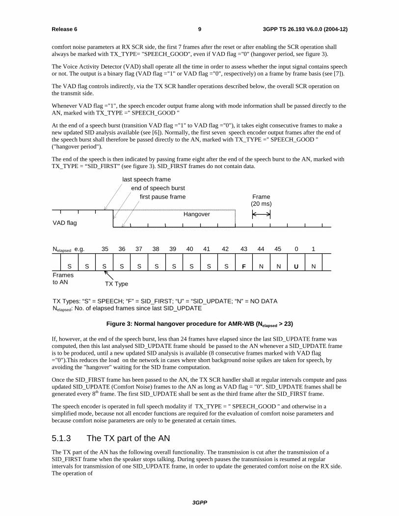
At the end of a speech burst (transition VAD flag ="1" to VAD flag ="0"), it takes eight consecutive frames to make a new updated SID analysis available (see [6]). Normally, the first seven speech encoder output frames after the end of the speech burst shall therefore be passed directly to the AN, marked with TX_TYPE =" SPEECH_GOOD " ("hangover period").
The end of the speech is then indicated by passing frame eight after the end of the speech burst to the AN, marked with TX_TYPE = “SID_FIRST” (see figure 3). SID_FIRST frames do not contain data.
S S S S S S S S S S F N N U N
VAD flag
last speech frameend of speech burst
first pause frame
Hangover
Nelapsed e.g. 35 36 37 38 39 40 41 42 43 44 45 0 1
Framesto AN TX Type
TX Types: “S” = SPEECH; “F” = SID_FIRST; “U” = “SID_UPDATE; “N” = NO DATANelapsed: No. of elapsed frames since last SID_UPDATE
Frame(20 ms)
Figure 3: Normal hangover procedure for AMR-WB (Nelapsed > 23)
If, however, at the end of the speech burst, less than 24 frames have elapsed since the last SID_UPDATE frame was computed, then this last analysed SID_UPDATE frame should be passed to the AN whenever a SID_UPDATE frame is to be produced, until a new updated SID analysis is available (8 consecutive frames marked with VAD flag ="0").This reduces the load on the network in cases where short background noise spikes are taken for speech, by avoiding the "hangover" waiting for the SID frame computation.
Once the SID_FIRST frame has been passed to the AN, the TX SCR handler shall at regular intervals compute and pass updated SID_UPDATE (Comfort Noise) frames to the AN as long as VAD flag = "0". SID_UPDATE frames shall be generated every 8th frame. The first SID_UPDATE shall be sent as the third frame after the SID_FIRST frame.
The speech encoder is operated in full speech modality if TX_TYPE = " SPEECH_GOOD " and otherwise in a simplified mode, because not all encoder functions are required for the evaluation of comfort noise parameters and because comfort noise parameters are only to be generated at certain times.
5.1.3 The TX part of the AN The TX part of the AN has the following overall functionality. The transmission is cut after the transmission of a SID_FIRST frame when the speaker stops talking. During speech pauses the transmission is resumed at regular intervals for transmission of one SID_UPDATE frame, in order to update the generated comfort noise on the RX side. The operation of

3GPP
3GPP TS 26.193 V6.0.0 (2004-12)10Release 6
the TX part of the AN is controlled by the TX SCR handler via the TX_TYPE.
All frames, marked with SPEECH_GOOD, SID_FIRST or SID_UPDATE shall be transmitted by the TX part of the AN.
5.2 Receive (RX) side A block diagram of the receive side SCR functions is shown in Figure 3 below.
ErrorCorrection &
Detection
RX SCR handler RX Access Network
Information bits
Mode Indication
RX_TYPE
SpeechDecoder
ComfortNoise
Generation
ErrorConcealment
AMR-WBFrame Type
Detection
TS26.201
Information bits
Frame Type
FQI
De-framing
Figure 4: Block diagram of the receive side SCR functions
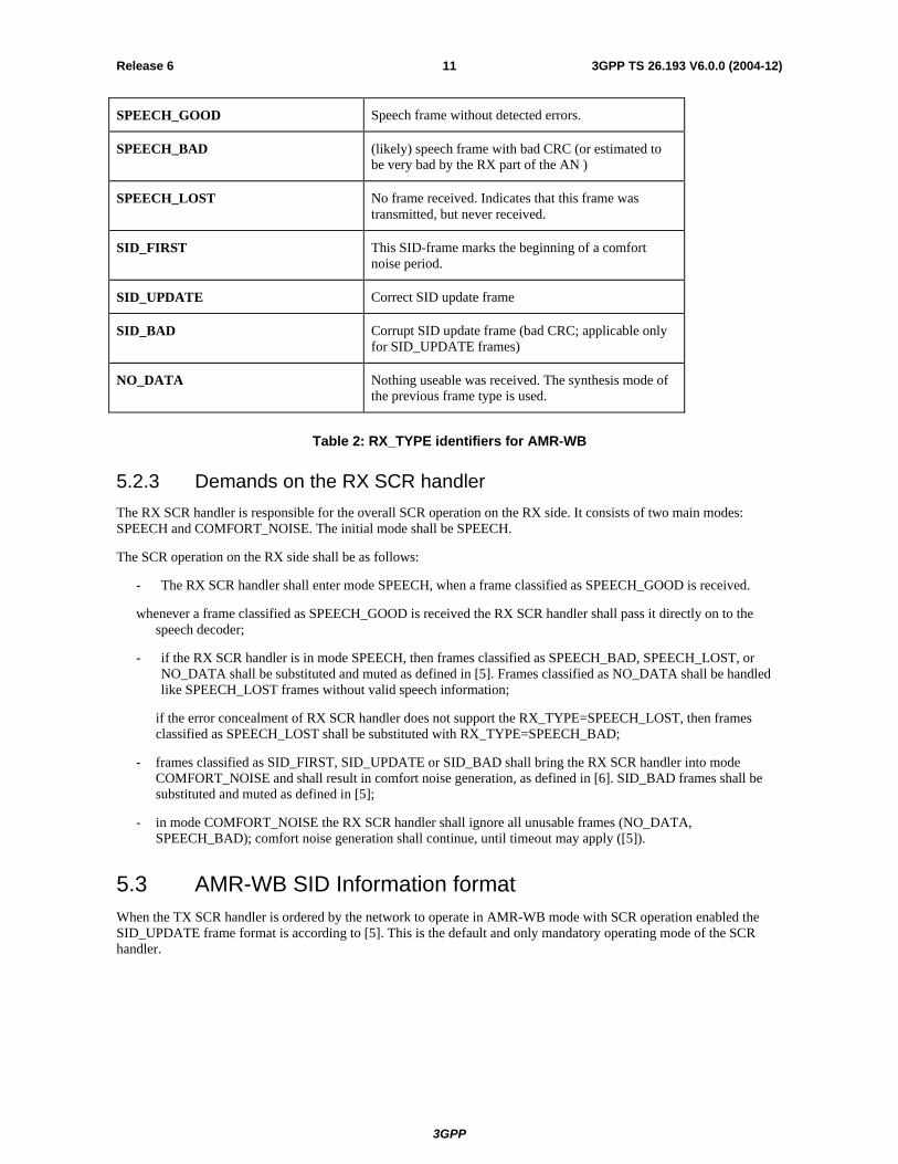
5.2.1 General operation The AN passes all the received traffic frames to the RX SCR handler, classified with RX_TYPE, as described in Table 2 (see TS 26.201). The RX SCR handles the frame accordingly.
RX_TYPE Information Bits
3GPP
3GPP TS 26.193 V6.0.0 (2004-12)11Release 6
SPEECH_GOOD Speech frame without detected errors.
SPEECH_BAD (likely) speech frame with bad CRC (or estimated to be very bad by the RX part of the AN )
SPEECH_LOST No frame received. Indicates that this frame was transmitted, but never received.
SID_FIRST This SID-frame marks the beginning of a comfort noise period.
SID_UPDATE Correct SID update frame
SID_BAD Corrupt SID update frame (bad CRC; applicable only for SID_UPDATE frames)
NO_DATA Nothing useable was received. The synthesis mode of the previous frame type is used.
Table 2: RX_TYPE identifiers for AMR-WB
5.2.3 Demands on the RX SCR handler The RX SCR handler is responsible for the overall SCR operation on the RX side. It consists of two main modes: SPEECH and COMFORT_NOISE. The initial mode shall be SPEECH.
The SCR operation on the RX side shall be as follows:
- The RX SCR handler shall enter mode SPEECH, when a frame classified as SPEECH_GOOD is received.
whenever a frame classified as SPEECH_GOOD is received the RX SCR handler shall pass it directly on to the speech decoder;
- if the RX SCR handler is in mode SPEECH, then frames classified as SPEECH_BAD, SPEECH_LOST, or NO_DATA shall be substituted and muted as defined in [5]. Frames classified as NO_DATA shall be handled like SPEECH_LOST frames without valid speech information;
if the error concealment of RX SCR handler does not support the RX_TYPE=SPEECH_LOST, then frames classified as SPEECH_LOST shall be substituted with RX_TYPE=SPEECH_BAD;
- frames classified as SID_FIRST, SID_UPDATE or SID_BAD shall bring the RX SCR handler into mode COMFORT_NOISE and shall result in comfort noise generation, as defined in [6]. SID_BAD frames shall be substituted and muted as defined in [5];
- in mode COMFORT_NOISE the RX SCR handler shall ignore all unusable frames (NO_DATA, SPEECH_BAD); comfort noise generation shall continue, until timeout may apply ([5]).
5.3 AMR-WB SID Information format When the TX SCR handler is ordered by the network to operate in AMR-WB mode with SCR operation enabled the SID_UPDATE frame format is according to [5]. This is the default and only mandatory operating mode of the SCR handler.

3GPP
3GPP TS 26.193 V6.0.0 (2004-12)12Release 6
Annex A: (normative) AMR-WB DTX handler for the GSM system
A.1 Scope The present document gives a description of the general baseband operation of Adaptive Multi-Rate Wideband speech traffic channels in the transmitter and in the receiver of GSM Mobile Stations (MS)s and Base Station Systems (BSS)s during Discontinuous Transmission (DTX).
For clarity, the description is structured according to the block diagrams in Figures 1 and 3. Except in the case described next, this structure of distributing the various functions between system entities is not mandatory for implementation, as long as the operation on the air interface and on the speech decoder output remains the same.
In the case of BSSs where the speech transcoder is located remote from the Base Transceiver Station (BTS), the implementation of the interfaces between the DTX handlers and the Radio Sub System (RSS) as described in the present document together with all their flags is mandatory, being part of the A-bis interface as described in GSM 08.60 and GSM 08.61.
The DTX functions described in this technical specification are mandatory for implementation in the GSM MSs implementing the AMR-WB speech codec. The receiver requirements are mandatory for implementation in all GSM BSSs implementing the AMR-WB speech codec, the transmitter requirements only for those BSSs where downlink DTX or Tandem Free Operation will be used.
A.2 References The following documents contain provisions which, through reference in this text, constitute provisions of the present document.
• References are either specific (identified by date of publication, edition number, version number, etc.) or non-specific.
• For a specific reference, subsequent revisions do not apply.
• For a non-specific reference, the latest version applies.
• A non-specific reference to an ETS shall also be taken to refer to later versions published as an EN with the same number.
• For this Release 1999 document, references to GSM documents are for Release 1999 versions (version 7.x.y).
[1] 3GPP TS 21.004: "Digital cellular telecommunication system (Phase 2+); Abbreviations and acronyms".
[2] 3GPP TS 24.008: "Digital cellular telecommunication system (Phase 2+); Mobile radio interface layer 3 specification".
[3] 3GPP TS 25.003: "Digital cellular telecommunication system (Phase 2+); Channel coding".
[4] 3GPP TS 25.005: "Digital cellular telecommunication system (Phase 2+); Radio transmission and reception".
[5] 3GPP TS 25.008: "Digital cellular telecommunication system (Phase 2+); Radio subsystem link control".
[6] 3GPP TS 25.009: "Digital cellular telecommunication system (Phase 2+); Link adaptation".
[7] 3GPP TS 26.171: "Digital cellular telecommunications system (Phase 2+); Adaptive Multi-Rate Wideband (AMR-WB) speech processing functions; General description".
3GPP
3GPP TS 26.193 V6.0.0 (2004-12)13Release 6
[8] 3GPP TS 26.173: "Digital cellular telecommunications system (Phase 2+); ANSI-C code for the GSM Adaptive Multi-Rate Wideband speech codec".
[9] 3GPP TS 26.174: "Digital cellular telecommunications system (Phase 2); Test vectors for the GSM Adaptive Multi-Rate Wideband speech codec".
[10] 3GPP TS 26.190: "Digital cellular telecommunications system (Phase 2+); Adaptive Multi-Rate Wideband speech transcoding".
[11] 3GPP TS 26.191: "Digital cellular telecommunications system (Phase 2+); Substitution and muting of lost frame for Adaptive Multi-Rate Wideband speech traffic channels".
[12] 3GPP TS 26.192: "Digital cellular telecommunications system (Phase 2+); Comfort noise aspects for Adaptive Multi-Rate Wideband speech traffic channels".
[13] 3GPP TS 26.194: "Digital cellular telecommunications system (Phase 2+); Voice Activity Detector (VAD) for Adaptive Multi-Rate Wideband speech traffic channels".
[14] 3GPP TS 28.060: "Digital cellular telecommunication system (Phase 2+); Inband control of remote transcoders and rate adaptors for Full Rate traffic channels".
[15] 3GPP TS 28.061: "Digital cellular telecommunication system (Phase 2+); Inband Control of Remote Transcoders and Rate Adaptors for Half Rate traffic channels".
[16] 3GPP TS 28.062: " Digital cellular telecommunications system; Inband Tandem Free Operation (TFO) of Speech Codecs".
A.3 Definitions, symbols and abbreviations
A.3.1 Definitions For the purpose of the present document, the following definitions apply.
frame: Time interval of 20 ms, corresponding to the time segmentation of the Adaptive Multi-Rate Wideband speech transcoder (3GPP TS 26.190 [9]), also used as a short term for a traffic frame.
traffic frame: Block of 132..397 information bits transmitted on the TCH/WFS or TCH/WHS speech traffic channels.
SID frame: Frame characterised by the SID (Silence Descriptor) gross bit patterns. It may convey information on the acoustic background noise.
speech frame: Traffic frame that has been classified as a SPEECH_GOOD, SPEECH_BAD or SPEECH_LOST frame.
VAD flag: Boolean flag, generated by the VAD algorithm defined in 3GPP TS 26.194 indicating the presence ("1") or the absence ("0") of a speech frame.
RX_TYPE: flag with eight values, generated by the RX radio subsystem, indicating to the RX DTX handler the type of data in the current frame. Refer to Table 2.
TX_TYPE: flag with eight values, generated by the TX DTX handler, indicating to the TX radio subsystem the type of data in the current frame. Refer to Table 1.
hangover period: A period of 7 frames added at the end of a speech burst in which VAD flag ="0" and TX_TYPE is "SPEECH".
A.3.2 Symbols For the purpose of the present document, the following symbols apply.
Nelapsed Number of elapsed frames since the last updated SID frame.

3GPP
3GPP TS 26.193 V6.0.0 (2004-12)14Release 6
A.3.3 Abbreviations For the purpose of the present document, the following abbreviations apply.
BSC Base Station Controller BSS Base Station System BTS Base Transceiver Station CHD Channel Decoder CHE Channel Encoder DTX Discontinuous Transmission ETS European Telecommunication Standard FACCH Fast Associated Control CHannel GSM Global System for Mobile Telecommunications MS Mobile Station RATSCCH Robust Amr Traffic Synchronised Control CHannel RSS Radio Sub System RX Receive SACCH Slow Associated Control CHannel SID SIlence Descriptor TX Transmit VAD Voice Activity Detector
For abbreviations not given in this subclause, see 3GPP TS 21.004.
A.4 General Discontinuous Transmission (DTX) is a mechanism, which allows the radio transmitter to be switched off most of the time during speech pauses for the following two purposes:
to save power in the Mobile Station (MS);
to reduce the overall interference level over the air interface.
DTX in uplink shall be in operation within the GSM MS, if commanded so by the network, see 3GPP TS 24.008. The MS shall handle DTX in downlink at any time, regardless, whether DTX in uplink is commanded or not.
A.4.1 General organisation The overall DTX mechanism described in the present document requires the following functions:
a Voice Activity Detector (VAD) on the transmit (TX) side;
evaluation of the background acoustic noise on the transmit (TX) side, in order to transmit characteristic parameters to the receive (RX) side;
generation on the receive (RX) side of a similar noise, called comfort noise, during periods where the radio transmission is switched off.
The Voice Activity Detector (VAD) is defined in 3GPP TS 26.194 and the comfort noise functions in 3GPP TS 26.192. Both are based partly on the speech transcoder and its internal variables, defined in 3GPP TS 26.190.
In addition to these functions, if the parameters arriving at the RX side are detected to be seriously corrupted by errors, the speech or comfort noise must be generated from substituted data in order to avoid seriously annoying effects for the listener. This function is defined in 3GPP TS 26.191.
An overall description of the speech processing parts can be found in 3GPP TS 26.171.
The description for Tandem Free Operation is given in 3GPP TS 28.062.
3GPP
3GPP TS 26.193 V6.0.0 (2004-12)15Release 6
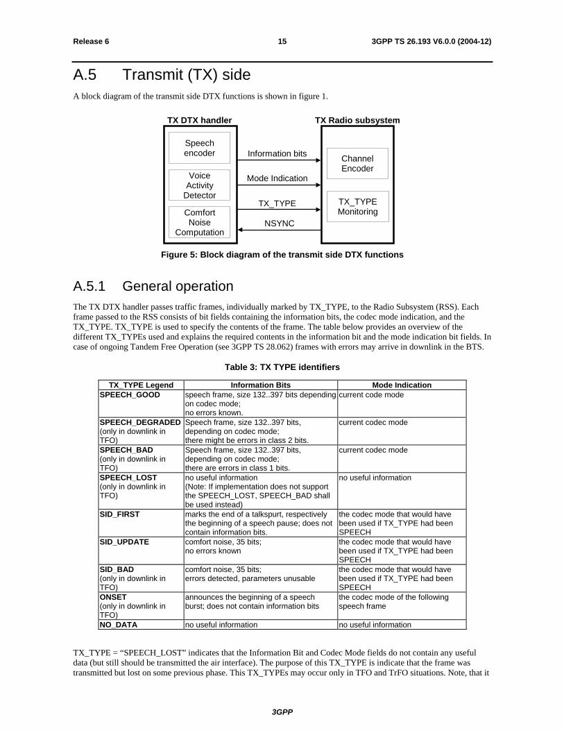
A.5 Transmit (TX) side A block diagram of the transmit side DTX functions is shown in figure 1.
TX DTX handler
Speechencoder
VoiceActivity
Detector
ComfortNoise
Computation
TX Radio subsystem
ChannelEncoder
TX_TYPEMonitoring
Information bits
Mode Indication
TX_TYPE
NSYNC
Figure 5: Block diagram of the transmit side DTX functions
A.5.1 General operation The TX DTX handler passes traffic frames, individually marked by TX_TYPE, to the Radio Subsystem (RSS). Each frame passed to the RSS consists of bit fields containing the information bits, the codec mode indication, and the TX_TYPE. TX_TYPE is used to specify the contents of the frame. The table below provides an overview of the different TX_TYPEs used and explains the required contents in the information bit and the mode indication bit fields. In case of ongoing Tandem Free Operation (see 3GPP TS 28.062) frames with errors may arrive in downlink in the BTS.
Table 3: TX TYPE identifiers
TX_TYPE Legend Information Bits Mode Indication SPEECH_GOOD
speech frame, size 132..397 bits depending on codec mode; no errors known.
current code mode
SPEECH_DEGRADED (only in downlink in TFO)
Speech frame, size 132..397 bits, depending on codec mode; there might be errors in class 2 bits.
current codec mode
SPEECH_BAD (only in downlink in TFO)
Speech frame, size 132..397 bits, depending on codec mode; there are errors in class 1 bits.
current codec mode
SPEECH_LOST (only in downlink in TFO)
no useful information (Note: If implementation does not support the SPEECH_LOST, SPEECH_BAD shall be used instead)
no useful information
SID_FIRST
marks the end of a talkspurt, respectively the beginning of a speech pause; does not contain information bits.
the codec mode that would have been used if TX_TYPE had been SPEECH
SID_UPDATE
comfort noise, 35 bits; no errors known
the codec mode that would have been used if TX_TYPE had been SPEECH
SID_BAD (only in downlink in TFO)
comfort noise, 35 bits; errors detected, parameters unusable
the codec mode that would have been used if TX_TYPE had been SPEECH
ONSET (only in downlink in TFO)
announces the beginning of a speech burst; does not contain information bits
the codec mode of the following speech frame
NO_DATA no useful information no useful information
TX_TYPE = “SPEECH_LOST” indicates that the Information Bit and Codec Mode fields do not contain any useful data (but still should be transmitted the air interface). The purpose of this TX_TYPE is indicate that the frame was transmitted but lost on some previous phase. This TX_TYPEs may occur only in TFO and TrFO situations. Note, that it
3GPP
3GPP TS 26.193 V6.0.0 (2004-12)16Release 6
is possible to replace SPEECH_LOST with SPEECH_BAD but this may degrade the quality of the error concealment in the receiving end because concealment may try to use part of the received parameters from the frame which do not contain any useful information.
TX_TYPE = “NO_DATA” indicates that the Information Bit and Codec Mode fields do not contain any useful data (and shall not be transmitted over the air interface). The purpose of this TX_TYPE is to provide the option to save transmission between the transcoder and the radio base station if a packet oriented transmission is used.
The scheduling of the frames for transmission on the air interface is controlled by the TX DTX handler by the use of the TX_TYPE field.
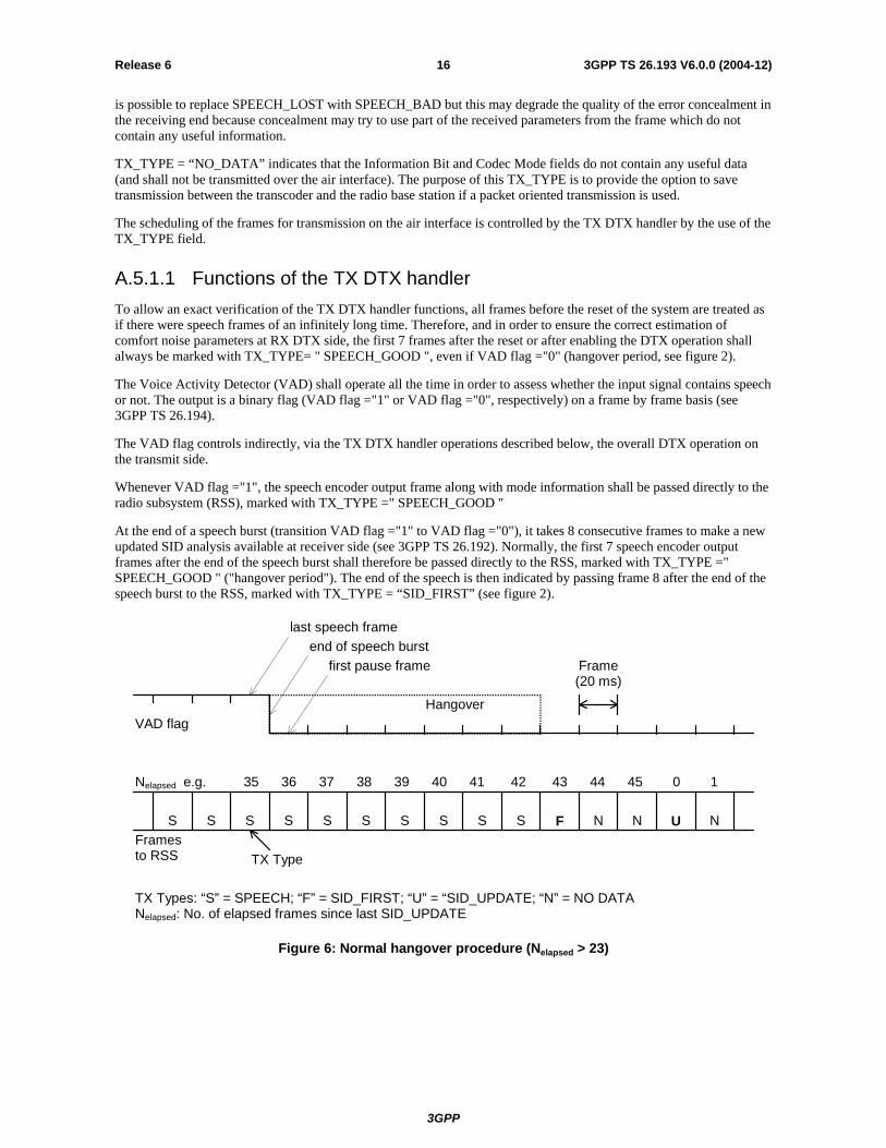
A.5.1.1 Functions of the TX DTX handler To allow an exact verification of the TX DTX handler functions, all frames before the reset of the system are treated as if there were speech frames of an infinitely long time. Therefore, and in order to ensure the correct estimation of comfort noise parameters at RX DTX side, the first 7 frames after the reset or after enabling the DTX operation shall always be marked with TX_TYPE= " SPEECH_GOOD ", even if VAD flag ="0" (hangover period, see figure 2).
The Voice Activity Detector (VAD) shall operate all the time in order to assess whether the input signal contains speech or not. The output is a binary flag (VAD flag ="1" or VAD flag ="0", respectively) on a frame by frame basis (see 3GPP TS 26.194).
The VAD flag controls indirectly, via the TX DTX handler operations described below, the overall DTX operation on the transmit side.
Whenever VAD flag ="1", the speech encoder output frame along with mode information shall be passed directly to the radio subsystem (RSS), marked with TX_TYPE =" SPEECH_GOOD "
At the end of a speech burst (transition VAD flag ="1" to VAD flag ="0"), it takes 8 consecutive frames to make a new updated SID analysis available at receiver side (see 3GPP TS 26.192). Normally, the first 7 speech encoder output frames after the end of the speech burst shall therefore be passed directly to the RSS, marked with TX_TYPE =" SPEECH_GOOD " ("hangover period"). The end of the speech is then indicated by passing frame 8 after the end of the speech burst to the RSS, marked with TX_TYPE = “SID_FIRST” (see figure 2).
S S S S S S S S S S F N N U N
VAD flag
last speech frameend of speech burst
first pause frame
Hangover
Nelapsed e.g. 35 36 37 38 39 40 41 42 43 44 45 0 1
Framesto RSS TX Type
TX Types: “S” = SPEECH; “F” = SID_FIRST; “U” = “SID_UPDATE; “N” = NO DATANelapsed: No. of elapsed frames since last SID_UPDATE
Frame(20 ms)
Figure 6: Normal hangover procedure (Nelapsed > 23)

3GPP
3GPP TS 26.193 V6.0.0 (2004-12)17Release 6
If, however, at the end of the speech burst, less than 24 frames have elapsed since the last SID_UPDATE frame was computed and passed to the RSS, then this last analysed SID_UPDATE frame shall repeatedly be passed to the RSS whenever a SID_UPDATE frame is to be produced, until a new updated SID analysis is available (8 consecutive frames marked with VAD flag ="0").This reduces the activity on the air in cases where short background noise spikes are taken for speech, by avoiding the "hangover" waiting for the SID frame computation.
Once the first SID analysis after the end of a speech burst has been computed and the SID_FIRST frame has been passed to the Radio Subsystem, the TX DTX handler shall at regular intervals compute and pass updated SID_UPDATE (Comfort Noise) frames to the Radio Subsystem (RSS) as long as VAD flag = "0". SID_UPDATE frames shall be generated every 8th frame. The first SID_UPDATE shall be sent as the third frame after the SID_FIRST frame.
The speech encoder is operated in full speech modality if TX_TYPE = " SPEECH_GOOD " and otherwise in a simplified mode, because not all encoder functions are required for the evaluation of comfort noise parameters and because comfort noise parameters are only to be generated at certain times.
In order to ensure TX/RX DTX handler synchronisation at handover, the uplink TX DTX handler in the MS shall accept messages from TX RSS with control parameter NSYNC, resulting in the following operation during a period of the next NSYNC frames:
• The TX DTX handler shall send SID_UPDATE instead of NO_DATA frames to the TX RSS.
• If, during this period of NSYNC frames, VAD flag is equal to 1 at least for one speech frame, TX DTX handler shall send SPEECH frames for the rest of the period of the NSYNC frames. Note the TX DTX handler shall send SPEECH frames at least for the duration of the hangover period.
A.5.1.2 Functions of the TX Radio Subsystem The TX Radio Subsystem has the following overall functionality. The radio transmission is cut after the transmission of a SID_FIRST frame when the speaker stops talking. During speech pauses the transmission is resumed at regular intervals for transmission of one SID_UPDATE frame, in order to update the generated comfort noise on the RX side (and to improve the measurement of the link quality by the RSS). Note that the transcoder knows what frames to send. In the case when nothing is to be transmitted it outputs frames marked with TX_TYPE = ”NO_DATA”.
Within the TX Radio Subsystem the TX_TYPE Monitoring unit controls the operation of the Channel Encoder (as specified in 3GPP TS 25.003) and the Transmission of the frame. Control input to the TX_TYPE Monitoring unit is the TX_TYPE. Control output and input to the Channel Encoder are indicators specifying the frame format. These frame format indicators are defined in 3GPP TS 25.003.
A.5.1.2.1 Functions of the TX Radio Subsystem for TCH/WFS
The TX Radio Subsystem operates in the following way regarding DTX (without TFO):
all frames marked with TX_TYPE = " SPEECH_GOOD " are scheduled for normal channel coding and transmission. The frame format for CHE operation shall be SPEECH. If, however, the previous frame was not of TX_TYPE = “SPEECH_GOOD”, an ONSET frame format followed by SPEECH_GOOD shall be signalled to the CHE;
for frames marked with TX_TYPE = “SID_FIRST” a SID_FIRST frame format is signalled to the CHE;
frames marked with TX_TYPE = “SID_UPDATE” are scheduled for SID_UPDATE frame channel coding and transmission. The frame format signalled to CHE is SID_UPDATE;
for frames marked with TX_TYPE = “NO_DATA” no processing or transmission is carried out.
If a SID_FIRST frame or a SID_UPDATE frame is stolen for Fast Associated Control Channel (FACCH) signalling purposes, then the subsequent frame shall be scheduled for transmission of the SID_FIRST or SID_UPDATE frame (whichever applies) instead.
SPEECH frames shall override possible SID_FIRST or SID_UPDATE frames in exceptional cases.
At handover, TX/RX DTX handler synchronisation shall be initiated. At the time instant before the MS starts sending to the new base station, a message shall be sent to the uplink TX DTX handler with the parameter NSYNC = 12.

3GPP
3GPP TS 26.193 V6.0.0 (2004-12)18Release 6
A.5.1.2.2 Functions of the Downlink TX Radio Subsystem for TFO
The TX Radio Subsystem in the BTS shall in addition operate in the following way regarding DTX, if TFO is ongoing (see 3GPP TS 28.062):
• Frames with TX_TYPE = SPEECH_GOOD, SID_FIRST and SID_UPDATE shall be handled as usual in DTX, regardless whether DTX in downlink is requested or not. Also NO_DATA shall be handled as usual, if DTX is requested.
• Frames with TX_TYPE = NO_DATA shall be replaced by SID_FILLER frames, if DTX in downlink is not requested. By this the radio transmission continues in downlink, although no parameters are transmitted in speech pauses on the Abis interface. The MS generates Comfort Noise in these speech pauses.
• Frames with TX_TYPE = SPEECH_DEGRADED shall be handled exactly like SPEECH_GOOD frames.
• For frame with TX_TYPE = SPEECH_BAD and SID_BAD the CHE shall perform its regular processing, but then shall invert CRC bits before convolutional encoding and transmitting the frames on the air interface. By this the error concealment mechanism in the MS is triggered to handle these corrupted frames.
• Frames with TX_TYPE = SPEECH_LOST shall be replaced by SPEECH_LOST_FILLER frames, if DTX in downlink is not requested. By this the radio transmission continues in downlink. The MS performs special lost frame handling operations for the frame.
• ONSET frames may be ignored by the TX Radio Subsystem and need not to be processed.
Definitions: SID_FILLER frames are like SID_BAD frames, but with all information bits set to “1”. The CRC bits shall artificially be inverted by the CHE before convolutional encoding and transmission. SPEECH_LOST_FILLER frames are like SPEECH_BAD frames, but with all information bits set to “1”. The CRC bits shall artificially be inverted by the CHE before convolutional encoding and transmission.
A.5.1.2.4 Functions of the TX Radio Subsystem for RATSCCH
During regular speech transmission (in the middle of a speech burst) RATSCCH replaces (steals) one speech frame (see 3GPP TS 25.009). Also in all non speech cases the RATSCCH shall be handled like speech. The respective RATSCCH frame formats shall be signalled to the CHE.
If RATSCCH has to be sent during a speech pause in DTX, then first an ONSET frame shall be signalled to the CHE, followed by the RATSCCH frame and finally by the respective SID_FIRST frame.
If a SID_UPDATE frame is affected by RATSCCH signalling, then the SID_UPDATE frame shall be re-scheduled for transmission immediately after the RATSCCH signalling.
FACCH should be handled in the same way as a RATSCCH, i.e. like a short speech burst.
3GPP
3GPP TS 26.193 V6.0.0 (2004-12)19Release 6
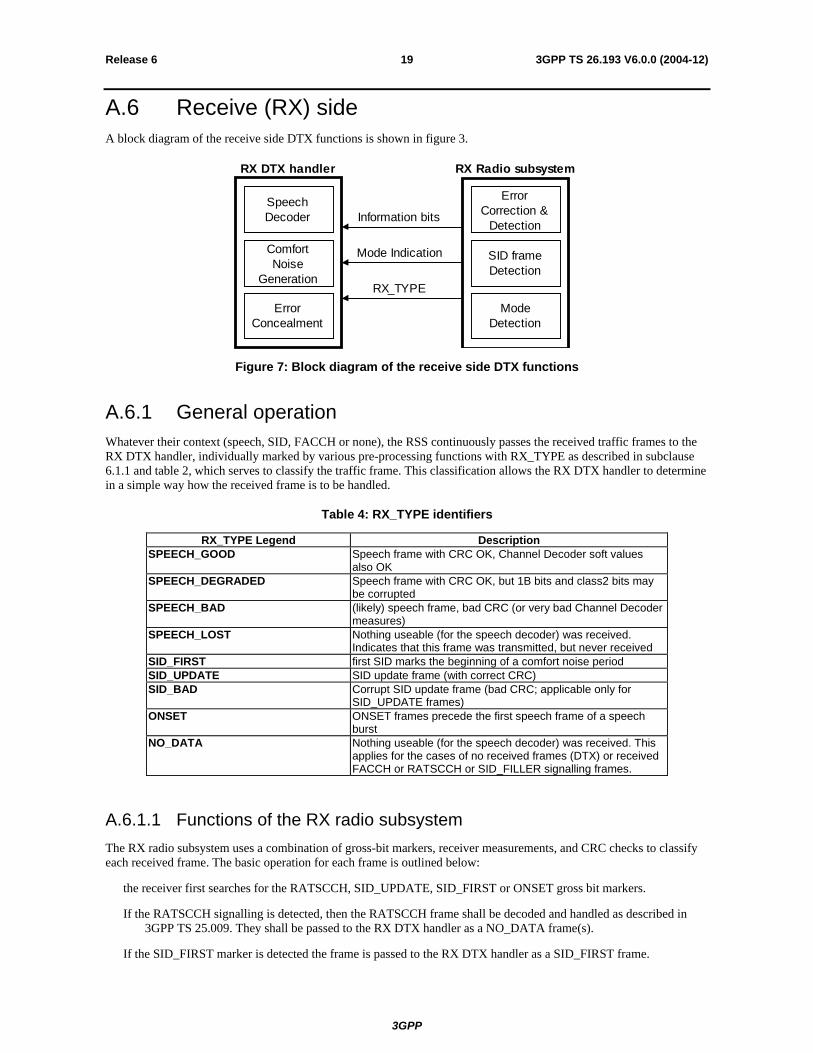
A.6 Receive (RX) side A block diagram of the receive side DTX functions is shown in figure 3.
RX DTX handler RX Radio subsystem
Information bits
Mode Indication
RX_TYPE
SpeechDecoder
ComfortNoise
Generation
ErrorConcealment
ModeDetection
ErrorCorrection &
Detection
SID frameDetection
Figure 7: Block diagram of the receive side DTX functions
A.6.1 General operation Whatever their context (speech, SID, FACCH or none), the RSS continuously passes the received traffic frames to the RX DTX handler, individually marked by various pre-processing functions with RX_TYPE as described in subclause 6.1.1 and table 2, which serves to classify the traffic frame. This classification allows the RX DTX handler to determine in a simple way how the received frame is to be handled.
Table 4: RX_TYPE identifiers
RX_TYPE Legend Description SPEECH_GOOD Speech frame with CRC OK, Channel Decoder soft values
also OK SPEECH_DEGRADED Speech frame with CRC OK, but 1B bits and class2 bits may
be corrupted SPEECH_BAD (likely) speech frame, bad CRC (or very bad Channel Decoder
measures) SPEECH_LOST Nothing useable (for the speech decoder) was received.
Indicates that this frame was transmitted, but never received SID_FIRST first SID marks the beginning of a comfort noise period SID_UPDATE SID update frame (with correct CRC) SID_BAD Corrupt SID update frame (bad CRC; applicable only for
SID_UPDATE frames) ONSET ONSET frames precede the first speech frame of a speech
burst NO_DATA Nothing useable (for the speech decoder) was received. This
applies for the cases of no received frames (DTX) or received FACCH or RATSCCH or SID_FILLER signalling frames.
A.6.1.1 Functions of the RX radio subsystem The RX radio subsystem uses a combination of gross-bit markers, receiver measurements, and CRC checks to classify each received frame. The basic operation for each frame is outlined below:
the receiver first searches for the RATSCCH, SID_UPDATE, SID_FIRST or ONSET gross bit markers.
If the RATSCCH signalling is detected, then the RATSCCH frame shall be decoded and handled as described in 3GPP TS 25.009. They shall be passed to the RX DTX handler as a NO_DATA frame(s).
If the SID_FIRST marker is detected the frame is passed to the RX DTX handler as a SID_FIRST frame.

3GPP
3GPP TS 26.193 V6.0.0 (2004-12)20Release 6
If the SID_UPDATE marker is detected, then the frame shall be decoded and passed to the RX DTX handler as a SID_UPDATE or a SID_BAD or a NO_DATA frame, depending on the CRC and the information bits, along with the comfort noise parameters, if applicable. A NO_DATA frame shall be passed on, if all information bits of a SID_UPDATE frame are set to “1” and the CRC is bad (see SID_FILLER in subclause 5.1.2.2).
- If the ONSET marker is detected, then an ONSET frame shall be passed to the RX DTX handler.
if neither SID_UPDATE nor SID_FIRST markers are detected, the frame shall be channel decoded assuming it to be a speech frame. A speech frame shall be passed on, if all information bits of speech frame are set to “1” and the CRC is bad (see SPEECH_LOST_FILLER in subclause 5.1.2.2). Depending on the CRC for speech frame channel decoding along with other receiver measurements the frame shall then be passed to the RX DTX handler marked as either SPEECH_GOOD, SPEECH_ DEGRADED, SPEECH_BAD, NO_DATA or SPEECH_LOST frame.
A.6.1.2 Functions of the RX DTX handler The RX DTX handler is responsible for the overall DTX operation on the RX side. It consists of two main modes: SPEECH and COMFORT_NOISE. The initial mode shall be SPEECH.
The DTX operation on the RX side shall be as follows:
The RX DTX handler shall enter mode SPEECH, when a frame classified as SPEECH_GOOD or SPEECH_DEGRADED is received. ONSET frames may be taken into account to identify the beginning of a speech burst;
whenever a frame classified as SPEECH_GOOD is received the RX DTX handler shall pass it directly on to the speech decoder;
if the RX DTX handler is in mode SPEECH, then frames classified as SPEECH_DEGRADED, SPEECH_BAD, SPEECH_LOST or NO_DATA shall be substituted and muted as defined in 3GPP TS 26.191. Frames classified as NO_DATA shall be handled like SPEECH_LOST frames without valid speech information;
if the error concealment of RX SCR handler does not support the RX_TYPE=SPEECH_LOST, then frames classified as SPEECH_LOST shall be substituted with RX_TYPE=SPEECH_BAD;
frames classified as SID_FIRST, SID_UPDATE or SID_BAD shall bring the RX DTX handler into mode COMFORT_NOISE and shall result in comfort noise generation, as defined in 3GPP TS 26.192. SID_BAD frames shall be substituted and muted as defined in 3GPP TS 26.191. In mode COMFORT_NOISE the RX DTX handler shall ignore all unusable frames (NO_DATA, SPEECH_BAD, SPEECH_LOST) delivered by the RSS; comfort noise generation shall continue, until timeout may apply (see 3GPP TS 26.191);
3GPP
3GPP TS 26.193 V6.0.0 (2004-12)21Release 6
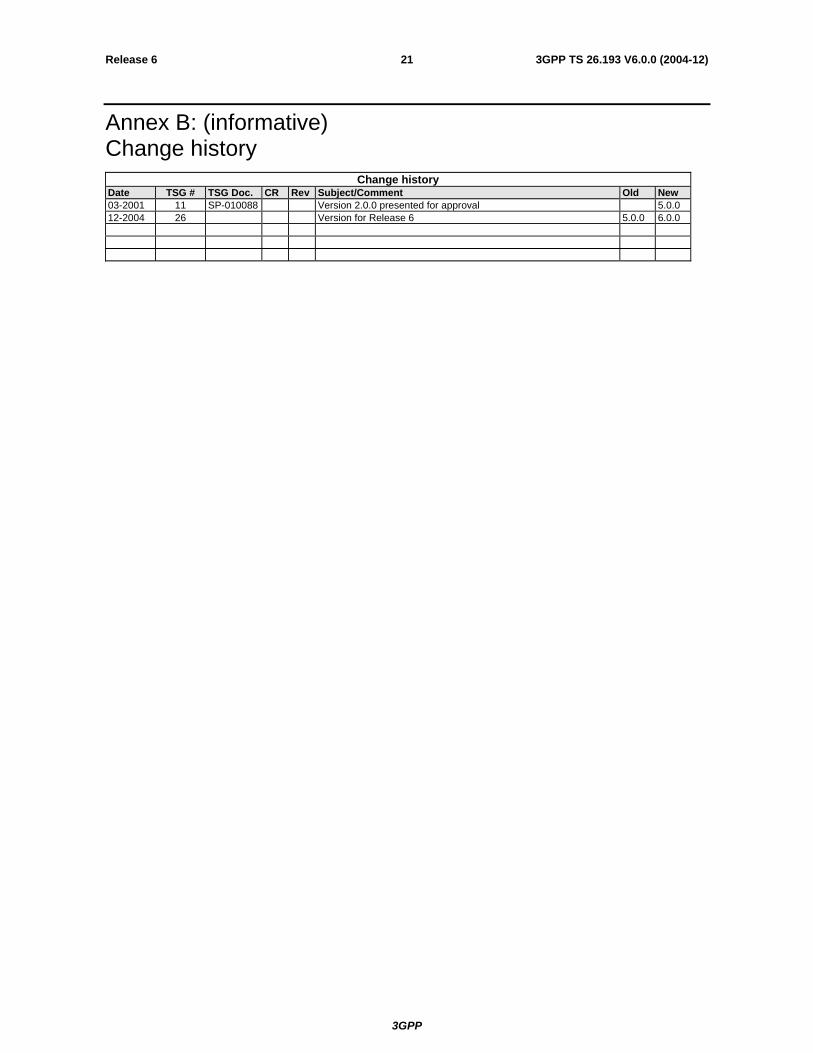
Annex B: (informative) Change history
Change history Date TSG # TSG Doc. CR Rev Subject/Comment Old New 03-2001 11 SP-010088 Version 2.0.0 presented for approval 5.0.0 12-2004 26 Version for Release 6 5.0.0 6.0.0