Embed Size (px)
Citation preview
ETSI TS 144 031 V7.6.0 (2007-10)Technical Specification
Digital cellular telecommunications system (Phase 2+);Location Services (LCS);
Mobile Station (MS) - Serving Mobile Location Centre (SMLC) Radio Resource LCS Protocol (RRLP)
(3GPP TS 44.031 version 7.6.0 Release 7)
GLOBAL SYSTEM FOR MOBILE COMMUNICATIONS
R
ETSI
ReferenceRTS/TSGG-0244031v760
KeywordsGSM
ETSI
650 Route des LuciolesF-06921 Sophia Antipolis Cedex - FRANCE
Tel.: +33 4 92 94 42 00 Fax: +33 4 93 65 47 16
Siret N° 348 623 562 00017 - NAF 742 CAssociation à but non lucratif enregistrée à laSous-Préfecture de Grasse (06) N° 7803/88
Important notice
Individual copies of the present document can be downloaded from:http://www.etsi.org
The present document may be made available in more than one electronic version or in print. In any case of existing or perceived difference in contents between such versions, the reference version is the Portable Document Format (PDF).
In case of dispute, the reference shall be the printing on ETSI printers of the PDF version kept on a specific network drive within ETSI Secretariat.
Users of the present document should be aware that the document may be subject to revision or change of status. Information on the current status of this and other ETSI documents is available at
http://portal.etsi.org/tb/status/status.asp
If you find errors in the present document, please send your comment to one of the following services:http://portal.etsi.org/chaircor/ETSI_support.asp
Copyright Notification
No part may be reproduced except as authorized by written permission.The copyright and the foregoing restriction extend to reproduction in all media.
© European Telecommunications Standards Institute 2007.All rights reserved.
DECTTM, PLUGTESTSTM and UMTSTM are Trade Marks of ETSI registered for the benefit of its Members.TIPHONTM and the TIPHON logo are Trade Marks currently being registered by ETSI for the benefit of its Members. 3GPPTM is a Trade Mark of ETSI registered for the benefit of its Members and of the 3GPP Organizational Partners.
ETSI TS 144 031 V7.6.0 (2007-10)13GPP TS 44.031 version 7.6.0 Release 7
Intellectual Property RightsIPRs essential or potentially essential to the present document may have been declared to ETSI. The information pertaining to these essential IPRs, if any, is publicly available for ETSI members and non-members, and can be found in ETSI SR 000 314: "Intellectual Property Rights (IPRs); Essential, or potentially Essential, IPRs notified to ETSI in respect of ETSI standards", which is available from the ETSI Secretariat. Latest updates are available on the ETSI Web server (http://webapp.etsi.org/IPR/home.asp).
Pursuant to the ETSI IPR Policy, no investigation, including IPR searches, has been carried out by ETSI. No guarantee can be given as to the existence of other IPRs not referenced in ETSI SR 000 314 (or the updates on the ETSI Web server) which are, or may be, or may become, essential to the present document.
ForewordThis Technical Specification (TS) has been produced by ETSI 3rd Generation Partnership Project (3GPP).
The present document may refer to technical specifications or reports using their 3GPP identities, UMTS identities or GSM identities. These should be interpreted as being references to the corresponding ETSI deliverables.
The cross reference between GSM, UMTS, 3GPP and ETSI identities can be found under http://webapp.etsi.org/key/queryform.asp.
ETSI
ETSI TS 144 031 V7.6.0 (2007-10)23GPP TS 44.031 version 7.6.0 Release 7
Contents
Intellectual Property Rights.........................................................................................................................2
Foreword.....................................................................................................................................................2
Foreword.....................................................................................................................................................5
1 Scope.................................................................................................................................................61.1 References...................................................................................................................................................61.2 Abbreviations..............................................................................................................................................6
2 Functionality of Protocol..................................................................................................................72.1 General........................................................................................................................................................72.2 Position Measurement Procedure................................................................................................................72.3 Assistance Data Delivery Procedure...........................................................................................................82.3a Positioning Capability Transfer Procedure.................................................................................................92.4 (void).........................................................................................................................................................102.5 Error Handling Procedures........................................................................................................................102.5.1 General................................................................................................................................................102.5.1a Message Too Short..............................................................................................................................102.5.2 Unknown Reference Number..............................................................................................................102.5.3 Missing Information Element or Component Element.......................................................................112.5.4 Incorrect Data......................................................................................................................................112.5.5 Repeated Component...........................................................................................................................112.5.6 (void)...................................................................................................................................................112.5.7 Missing Component.............................................................................................................................112.5.8 Unforeseen Component.......................................................................................................................122.5.8a RRLP Procedure..................................................................................................................................122.5.9 Pseudo-Segmentation..........................................................................................................................12
3 Message Structure...........................................................................................................................123.1 General Format of RRLP Message...........................................................................................................123.2 Reference Number IE................................................................................................................................133.3 Component IE...........................................................................................................................................14
4 Components....................................................................................................................................144.1 Measure Position Request.........................................................................................................................154.2 Measure Position Response.......................................................................................................................154.3 Assistance Data.........................................................................................................................................164.4 Assistance Data Acknowledgement..........................................................................................................164.5 Protocol Error............................................................................................................................................164.6 Positioning Capability Request.................................................................................................................174.7 Positioning Capability Response...............................................................................................................17
5 Elements of Components................................................................................................................175.1 ASN.1 Description....................................................................................................................................17
6 TOM Protocol Header for RRLP Transport...................................................................................386.1 General......................................................................................................................................................386.2 Remaining Octets of TOM Protocol Header for RRLP............................................................................38
Annex A (informative): Description of Components...................................................................40A.1 Introduction...............................................................................................................................................40A.2 Measure Position Request.........................................................................................................................40A.2.1 General................................................................................................................................................40A.2.2 Elements..............................................................................................................................................41A.2.2.1 Positioning Instructions Element...................................................................................................41A.2.2.1a GANSS Positioning Method Element...........................................................................................42A.2.2.2 E-OTD Reference BTS for Assistance Data Element...................................................................42A.2.2.3 E-OTD Measurement Assistance Data Element............................................................................43A.2.2.4 E-OTD Measurement Assistance Data for System Information List Element..............................45
ETSI
ETSI TS 144 031 V7.6.0 (2007-10)33GPP TS 44.031 version 7.6.0 Release 7
A.2.2.4a GPS Time Assistance Measurement Request element..................................................................47A.2.2.4b GPS Reference Time Uncertainty element....................................................................................48A.2.2.4c Velocity Request element..............................................................................................................48A.2.2.4d GANSS Carrier-Phase Measurement Request Element................................................................48A.2.2.4e GANSS TOD - GSM Time Association Request Element............................................................48A.2.2.4f Required Response Time...............................................................................................................48A.2.2.5 Extended Reference IE..................................................................................................................48A.3 Measure Position Response.......................................................................................................................49A.3.1 General................................................................................................................................................49A.3.2 Elements..............................................................................................................................................50A.3.2.1 Multiple Sets Element....................................................................................................................50A.3.2.2 Reference BTS Identity Element...................................................................................................50A.3.2.3 E-OTD Measurement Information Element..................................................................................51A.3.2.3a E-OTD Measurement Extended Information Element..................................................................55A.3.2.4 Location Information Element.......................................................................................................56A.3.2.5 GPS Measurement Information Element.......................................................................................57A.3.2.6 Location Information Error Element.............................................................................................61A.3.2.6a GPS Time Assistance Measurements Element..............................................................................61A.3.2.6b Velocity Estimate Element............................................................................................................62A.3.2.7 Extended Reference IE..................................................................................................................63A.3.2.8 Uplink RRLP Pseudo Segmentation Indication.............................................................................63A.3.2.9 GANSS Location Information Element.........................................................................................63A.3.2.10 GANSS Measurement Information Element.................................................................................66A.3.2.10.1 GANSS Generic Measurement Information Element...................................................................69A.4 Assistance Data.........................................................................................................................................72A.4.1 General................................................................................................................................................72A.4.2 Elements..............................................................................................................................................72A.4.2.1 E-OTD Reference BTS for Assistance Data Element...................................................................72A.4.2.2 E-OTD Measurement Assistance Data Element............................................................................72A.4.2.3 E-OTD Measurement Assistance Data for System Information List Element..............................72A.4.2.4 GPS Assistance Data Element.......................................................................................................73A.4.2.4a GPS Time Assistance Measurement Request Element..................................................................85A.4.2.4b GPS Reference Time Uncertainty Element...................................................................................85A.4.2.5 More Assistance Data To Be Sent Element...................................................................................85A.4.2.6 GANSS Assistance Data................................................................................................................85A.4.2.6.1 GANSS Common Assistance Data................................................................................................86A.4.2.6.2 GANSS Generic Assistance Data..................................................................................................88A.4.2.7 GANSS Carrier-Phase Measurement Request Element..............................................................102A.4.2.8 GANSS TOD - GSM Time Association Request Element..........................................................102A.5 Assistance Data Acknowledgement........................................................................................................102A.5.1 General..............................................................................................................................................102A.6 Protocol Error..........................................................................................................................................102A.6.1 General..............................................................................................................................................102A.6.2 Extended Reference IE......................................................................................................................102A.7 Positioning Capability Request...............................................................................................................103A.7.1 General..............................................................................................................................................103A.8 Positioning Capability Response.............................................................................................................103A.8.1 General..............................................................................................................................................103A.8.2 Elements............................................................................................................................................103A.8.2.1 Positioning Capabilities...............................................................................................................103A.8.2.2 Assistance Data Supported..........................................................................................................104A.8.2.3 Assistance Data Needed...............................................................................................................106
Annex B (informative): Change History.....................................................................................107
History.....................................................................................................................................................109
ETSI
ETSI TS 144 031 V7.6.0 (2007-10)43GPP TS 44.031 version 7.6.0 Release 7
ForewordThis Technical Specification has been produced by the 3rd Generation Partnership Project (3GPP).
The contents of the present document are subject to continuing work within the TSG and may change following formal TSG approval. Should the TSG modify the contents of the present document, it will be re-released by the TSG with an identifying change of release date and an increase in version number as follows:
Version x.y.z
where:
x the first digit:
1 presented to TSG for information;
2 presented to TSG for approval;
3 or greater indicates TSG approved document under change control.
y the second digit is incremented for all changes of substance, i.e. technical enhancements, corrections, updates, etc.
z the third digit is incremented when editorial only changes have been incorporated in the document.
ETSI
ETSI TS 144 031 V7.6.0 (2007-10)53GPP TS 44.031 version 7.6.0 Release 7
1 ScopeThe present document contains the definition of the Radio Resource LCS Protocol (RRLP) to be used between the Mobile Station (MS) and the Serving Mobile Location Centre (SMLC).
Clause 2 defines the functionality of the protocol. Clause 3 describes the message structure, and Clause 4 the structure of components. Clause 5 contains the ASN.1 description of the components.
1.1 ReferencesThe following documents contain provisions which, through reference in this text, constitute provisions of the present document.
References are either specific (identified by date of publication, edition number, version number, etc.) or non-specific.
For a specific reference, subsequent revisions do not apply.
For a non-specific reference, the latest version applies. In the case of a reference to a 3GPP document (including a GSM document), a non-specific reference implicitly refers to the latest version of that document in the same Release as the present document.
[1] 3GPP TR 21.905: "Vocabulary for 3GPP Specifications".
[2] 3GPP TS 43.059: "Functional Stage 2 Description of Location Services in GERAN".
[3] 3GPP TS 29.002: "Mobile Application Part (MAP) specification".
[4] ITU-T Recommendation X.691: "Information technology - ASN.1 encoding rules: Specification of Packed Encoding Rules (PER)".
[5] ITU-T Recommendation X.680: "Information technology - Abstract Syntax Notation One (ASN.1): Specification of basic notation".
[6] 3GPP TS 23.032: "Universal Geographical Area Description (GAD)".
[7] 3GPP TS 49.031: "Location Services (LCS); Base Station System Application Part LCS Extension (BSSAP-LE)".
[8] ICD-GPS-200, Navstar GPS Space Segment/Navigation User Interfaces.
[9] RTCM-SC104, RTCM Recommended Standards for Differential GNSS Service (v.2.2).
[10] 3GPP TS 44.064: "General Packet Radio Service (GPRS); Mobile Station - Serving GPRS Support Node (MS-SGSN); Logical Link Control (LLC) layer specification".
[11] Galileo OS Signal in Space ICD (OS SIS ICD), Draft 0, Galileo Joint Undertaking, May 23rd, 2006.
[12] IS-GPS-200, Revision D, Navstar GPS Space Segment/Navigation User Interfaces, December 7th, 2004.
1.2 AbbreviationsFor the purposes of the present document, the abbreviations given in 3GPP TR 21.905 or in 3GPP TS 43.059 apply.
ETSI
ETSI TS 144 031 V7.6.0 (2007-10)63GPP TS 44.031 version 7.6.0 Release 7
2 Functionality of Protocol
2.1 GeneralThe present document defines one generic RRLP message that is used to transfer Location Services (LCS) related information between the Mobile Station (MS) and the Serving Mobile Location Centre (SMLC). Usage of the RRLP protocol on a general level is described in 3GPP TS 43.059 that includes Stage 2 description of LCS.
One message includes one of the following components:
- Measure Position Request;
- Measure Position Response;
- Assistance Data;
- Assistance Data Acknowledgement;
- Protocol Error;
- Positioning Capability Request;
- Positioning Capability Response.
Next sub-clauses describe the usage of these components.
Delivery of components may be supported in the RRLP level using pseudo-segmentation by sending several shorter messages instead of one long message. Any assistance data that is successfully delivered to an MS and acknowledged prior to the interruption of the positioning procedure by an event like handover, or by any other event that causes an MS to terminate the positioning procedure or delivery of assistance data (see 3GPP TS 43.059), shall be retained by the MS and need not be resent by the SMLC when positioning or delivery of assistance data is again re-attempted.
The RRLP maximum PDU size is 242 octets. If the amount of data that needs to be sent is larger than RRLP maximum PDU size, the RRLP pseudo-segmentation shall be used. The RRLP pseudo-segmentation is the use of several RRLP components (one in each RRLP message) to deliver a large amount of information. For SMLC to MS messages, the Assistance Data component is the one that is sent several times in order to deliver the information. For MS to SMLC messages, the Measure Position Response component may be sent twice in order to deliver the information. Legacy MS and SMLC (3GPP Rel-4 or older) may send RRLP components that are larger than the RRLP maximum PDU size. In this case lower level segmentation will be used.
2.2 Position Measurement ProcedureThe purpose of this procedure is to enable the SMLC to request for position measurement data or location estimate from the MS, and the MS to respond to the request with measurements or location estimate.
ETSI
ETSI TS 144 031 V7.6.0 (2007-10)73GPP TS 44.031 version 7.6.0 Release 7
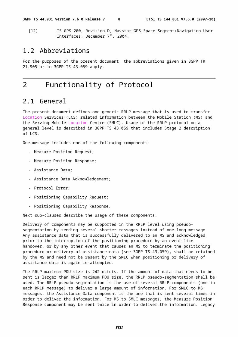
Figure 2.1: Position Measurement procedure
1. The Measure Position Request component and any Assistance Data Delivery Procedure may be preceded by a Positioning Capability Transfer procedure (see sub-clause 2.3a) to transfer the MS positioning capabilities to the SMLC.
2. The Measure Position Request component may be preceded by an Assistance Data Delivery Procedure (see sub-clause 2.3) to deliver some or all of the entire set of assistance data that is needed by the subsequent positioning procedure (steps 3-5).
3. The SMLC sends the Measure Position Request component in a RRLP message to the MS. The component includes QoS, other instructions, and possible assistance data to the MS. The RRLP message contains a reference number and an extended reference ID of the request.
4. The MS sends a RRLP message containing the Protocol Error component to the SMLC, if there is a problem that prevents the MS to receive a complete and understandable Measure Position Request component. The RRLP message contains the reference number and, if available, the extended reference ID included in the Measure Position Request received incomplete. The Protocol Error component includes a more specific reason. When the SMLC receives the Protocol Error component, it may try to resend the Measure Position Request (go back to the step 3), abort location, or start a new position measurement procedure (e.g. with updated assistance data).
5. The MS tries to perform the requested location measurements, and possibly calculates it own position. When the MS has location measurements, location estimate, or an error indication (measurements/location estimation not possible), it sends the results in the Measure Position Response component to the SMLC. The RRLP message contains the reference number and, if received, the extended reference ID of the request originally received in the step 3. The MS may optionally send one additional Measure Position Response component in a second RRLP message to the SMLC if the amount of information it needs to transfer to the SMLC is too large to fit into one single Measure Position Response component (uplink RRLP pseudo-segmentation). This RRLP message also contains the reference number and, if received, the extended reference ID of the request originally received in the step 3. If two components are sent, the MS shall indicate in the first component that it is the first of many components and in the second one that it is the second of many components. If there is a problem that prevents the SMLC to receive a complete and understandable Measure Position Response component, the SMLC may decide to abort location, or start a new position measurement procedure instead. If additional Measure Position Response components are received by the SMLC after the 1st and optional 2nd one, they shall be ignored.
2.3 Assistance Data Delivery ProcedureThe purpose of this procedure is to enable the SMLC to send assistance data to the MS related to position measurement and/or location calculation. Notice that RRLP protocol is not used by the MS to request assistance data, only to deliver it to the MS. The entire set of assistance data (i.e. the total amount of assistance data that the SMLC has decided to send in the current procedure) may be delivered in one or several Assistance Data components. In this case steps 1 and 3 below may be repeated several times by the SMLC. If several components are sent, the SMLC shall await the acknowledgement of each component before the next Assistance Data component is sent. If Assistance Data Delivery is
ETSI
ETSI TS 144 031 V7.6.0 (2007-10)83GPP TS 44.031 version 7.6.0 Release 7
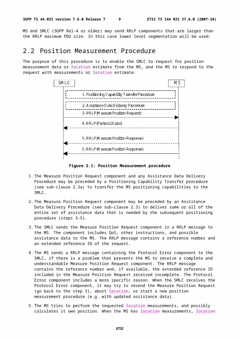
used as part of the Position Measurement Procedure, as described in sub-clause 2.2, then some assistance data may be delivered in the final RRLP Measure Position Request.
Figure 2.2: Assistance Data Delivery procedure
1. The SMLC sends the Assistance Data component to the MS. The component includes assistance data for location measurement and/or location calculation. The RRLP message contains a reference number and an extended reference ID of the delivery. The More Assistance Data To Be Sent Element in the Assistance Data component is used by the SMLC to indicate to the MS if either more Assistance Data components (in the current Assistance Data Delivery procedure) or a final RRLP Measure Position Request (if the Assistance Data Delivery Procedure forms part of a Position Measurement procedure as described in sub-clause 2.2) will be sent.
2. The MS sends a RRLP message containing the Protocol Error component to the SMLC, if there is a problem that prevents the MS to receive a complete and understandable Assistance Data component. The RRLP message contains the reference number and, if available, the extended reference ID included in the Assistance Data component received incomplete. The Protocol Error component includes a more specific reason. When the SMLC receives the Protocol Error component, it may try to resend the Assistance Data component (go back to the step 1), send a new measure Assistance Data set (e.g. with updated assistance data), or abort the delivery.
3. When the MS has received a complete Assistance Data component, it send the Assistance Data Acknowledgement component to the SMLC. The RRLP message contains the reference number of the Assistance Data originally received in step 1.
2.3a Positioning Capability Transfer ProcedureThe purpose of this procedure is to enable the SMLC to obtain the positioning capabilities of the MS, the types of assistance supported and the types of assistance data that may be needed from the SMLC. MS support for this procedure can be indicated to the SMLC using the MS Classmark 3 IE for GSM (see 3GPP TS 24.008), the PS LCS Capability IE for GERAN Gb mode (see 3GPP TS 24.008) and the MS Positioning Capability IE for GERAN Iu mode (see 3GPP TS 44.118).
Figure 2.3: Positioning Capability Transfer procedure
ETSI
ETSI TS 144 031 V7.6.0 (2007-10)93GPP TS 44.031 version 7.6.0 Release 7
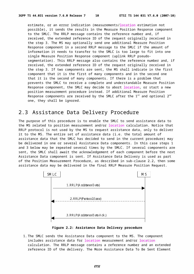
1. The SMLC sends the Positioning Capability Request component to the MS. The RRLP message contains a reference number and an extended reference ID of the request.
2. The MS sends a RRLP message containing the Protocol Error component to the SMLC, if there is a problem that prevents the MS to receive a complete and understandable Positioning Capability Request component. The RRLP message contains the reference number and the extended reference ID included in the Positioning Capability Request component. The Protocol Error component includes a more specific reason. When the SMLC receives the Protocol Error component, it may try to resend the Positioning Capability Request component (go back to the step 1) or abort the request.
3. When the MS has received a complete Positioning Capability Request component, it sends the Positioning Capability Response component to the SMLC. The component shall include the positioning capabilities of the MS and the types of supported assistance data. The component may include the types of assistance needed by the MS to obtain a location estimate or positioning measurements. The RRLP message also contains the reference number and extended Reference ID of the Positioning Capability Request originally received in step 1.
2.4 (void)
2.5 Error Handling Procedures
2.5.1 GeneralIn this sub-clause it is described how a receiving entity behaves in cases when it receives erroneous data or detects that certain data is missing.
2.5.1a Message Too ShortWhen MS receives a RRLP message, that is too short to contain all mandatory IEs, the MS sends a Protocol Error component with indication "Message Too Short". If the Reference Number can be found, it is included. If the Reference Number is not available, the Reference Number of the RRLP message carrying the Protocol Error component is set to '0'. If the Extended Reference IE can be found, it shall be included in the returned Protocol Error Component. If the Extended Reference IE is not available, an Extended Reference IE shall not be included. The original sending entity that receives the Protocol Error, may then resend the original message, or abort the procedure.
2.5.2 Unknown Reference NumberA SMLC detects that it has received a RRLP message with an unknown or invalid Reference Number, when one or more of the following conditions occur:
- a Measure Position Response, Assistance Data Acknowledgement, or Protocol Error component is received with a Reference Number that the SMLC has not sent in a Measure Position Request, or Assistance Data components during a pending Position Measurement or Assistance Data Delivery procedures.
- a Measure Position Response or Protocol Error component is received with an Extended Reference IE value that the SMLC has not sent in a Measure Position Request or Assistance Data component during a pending Position Measurement or Assistance Data Delivery procedures.
- a Measure Position Response or Protocol Error component is received with a Reference Number and an Extended Reference IE value that the SMLC has not sent together in the same Measure Position Request or the same Assistance data component during a pending Position Measurement or Assistance Data Delivery procedures.
The SMLC shall then discard the message. If the SMLC receives a Measure Position Response or a Protocol Error component containing no Extended Reference ID, then the SMLC shall assume that the target MS is for Release 4 or earlier and shall only verify the received Reference Number.
ETSI
ETSI TS 144 031 V7.6.0 (2007-10)103GPP TS 44.031 version 7.6.0 Release 7
2.5.3 Missing Information Element or Component ElementWhen MS receives a RRLP message, that does not contain IEs or component elements expected to be present, the MS sends a Protocol Error component with indication "Missing Information Element or Component Element". If the Reference Number can be found, it is included. If the Reference Number is not available, the Reference Number of the RRLP message carrying the Protocol Error component is set to '0'. If the Extended Reference IE can be found, it shall be included in the returned Protocol Error Component. If the Extended Reference IE is not available, an Extended Reference IE shall not be included. The SMLC that receives the Protocol Error, may then resend the original message, or abort the procedure.
2.5.4 Incorrect DataWhen MS receives a RRLP message, that is contains IEs or elements of components that are syntactically incorrect, the MS sends a Protocol Error component with indication "Incorrect Data". If the Reference Number can be found, it is included. If the Reference Number is not available, the Reference Number of the RRLP message carrying the Protocol Error component is set to '0'. If the Extended Reference IE can be found, it shall be included in the returned Protocol Error Component. If the Extended Reference IE is not available, an Extended Reference IE shall not be included. The SMLC that receives the Protocol Error, may then resend the original message, or abort the procedure.
2.5.5 Repeated ComponentWhen after the reception of a Measure Position Request component, but before responding with a Measure Position Response or a Protocol Error component, the MS receives a new RRLP message with the Measure Position Request component, it acts as follows:
- if the old and new Measure Position Request components have the same Reference Number and, if included, the same Extended Reference IE, the MS ignores the later component;
- if the old and new Measure Position Request components have different Reference Numbers or, if included, different Extended Reference IEs or if one Measure Position Request component (old or new) contains an Extended Reference IE but the other component does not, the MS aborts activity for the former component, and starts to acts according to the later component, and sends a response to that.
When after the reception of an Assistance Data component, but before responding with an Assistance Data Acknowledgement or a protocol Error component, the MS receives a new RRLP message with the Assistance Data component, it acts as follows:
- if the old and new an Assistance Data components have the same Reference Number and, if included, the same Extended Reference IE and if pseudo-segmentation does not apply (see sub-clause 2.5.9), the MS ignores the later component;
- if the old and new Assistance Data components have different Reference Numbers or, if included, different Extended Reference IEs or if one Assistance Data component (old or new) contains an Extended Reference IE but the other component does not, the MS ignores the former component and sends an acknowledgement to the latter component.
When after the reception of an Measure Position Response component, the SMLC receives a new RRLP message with the Measure Position Response component, it acts as follows:
- if the old and new Measure Position Response components have the same Reference Number and, if included, the same Extended Reference IE values, the SMLC may ignore the later component;
2.5.6 (void)
2.5.7 Missing ComponentWhen the SMLC sends a Measure Position Request component to the MS, it starts a timer. If the timer expires before the SMLC receives the last Measure Position Response component or a Protocol Error component from the MS with the same Reference Number and, if included, the same Extended Reference IE value as in the sent component, it may abort location attempt or send a new Measure Position Request.
ETSI
ETSI TS 144 031 V7.6.0 (2007-10)113GPP TS 44.031 version 7.6.0 Release 7
When the SMLC receives a Measure Position Response component with the same Reference Number and, if included, the same Extended Reference IE value as in the sent component indicating that it is the second of many segments, but the first of the many segments was never received by the SMLC, it may abort location attempt or send a new Measure Position Request.
When the SMLC sends a Assistance Data component to the MS, it starts a timer. If the timer expires before the SMLC receives a Assistance Data Acknowledgement or Protocol Error component from the MS with the same Reference Number as in the sent component and, in the case of a Protocol Error component, either the same extended reference ID as in the sent component or no extended reference ID, it may abort delivery attempt or send a new Assistance Data.
2.5.8 Unforeseen ComponentWhen the MS receives a complete Assistance Data pseudo-segmentation sequence or an Assistance Data component that was sent without pseudo-segmentation, that it is not expecting, MS may discard it.
2.5.8a RRLP ProcedureThe MS and SMLC shall only support one RRLP procedure at a time for either positioning or delivery of assistance data. The normal sequence of events for either procedure is defined in sub-clause 2.2 or sub-clause 2.3, respectively. If the MS is engaged in an RRLP procedure and receives a correctly encoded RRLP message from the SMLC that starts a new procedure, the MS shall abort the first procedure without sending a response and start the second.
2.5.9 Pseudo-SegmentationWhen the SMLC employs pseudo-segmentation to send an RRLP Measure Position Request message or an RRLP Assistance Data message, the SMLC shall send one or more RRLP Assistance Data components followed by:
- a final RRLP Measure Position Request component (see sub-clause 2.2) or
- a final RRLP Assistance Data component (see sub-clause 2.3).
The SMLC shall indicate in all but the final component (Measure Position Request or Assistance Data, respectively) that more components are on the way.
When an MS receives an Assistance Data component indicating that more components are on the way, the MS may store the contents of the component. If the MS receives a subsequent Assistance Data component or a final Measure Position Request component that is correctly encoded, the MS shall assume that the new component continues the pseudo-segmentation of the earlier component and may then store the contents of the new component. If the new component is an Assistance Data component indicating that no more components are on the way or if it is a Measure Position Request, the MS shall assume that pseudo-segmentation is complete. The MS may then employ the rules defined in sub-clause 2.5.5 to verify if the new message is a repeated duplicate of a previous message.
3 Message Structure
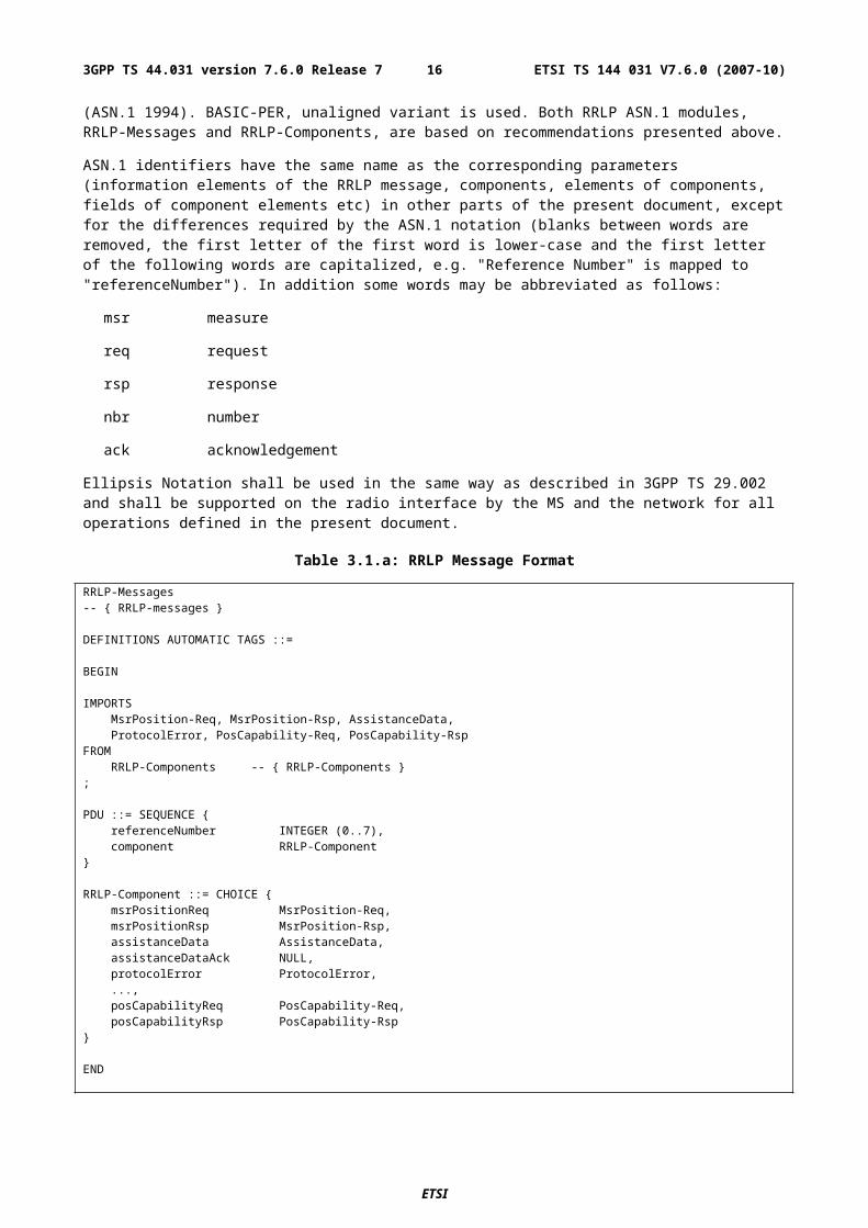
3.1 General Format of RRLP MessageThe general format of the RRLP message is given below, and based on:
- ITU-T Recommendation X.680;
- ITU-T Recommendation X.691;
and is consistent with these ITU-T recommendations. Also further definitions in the present document are based on ASN.1/94 defined in ITU-T Recommendation X.680 (ASN.1 1994). BASIC-PER, unaligned variant is used. Both RRLP ASN.1 modules, RRLP-Messages and RRLP-Components, are based on recommendations presented above.
ASN.1 identifiers have the same name as the corresponding parameters (information elements of the RRLP message, components, elements of components, fields of component elements etc) in other parts of the present document, except for the differences required by the ASN.1 notation (blanks between words are removed, the first letter of the first word
ETSI
ETSI TS 144 031 V7.6.0 (2007-10)123GPP TS 44.031 version 7.6.0 Release 7
is lower-case and the first letter of the following words are capitalized, e.g. "Reference Number" is mapped to "referenceNumber"). In addition some words may be abbreviated as follows:
msr measure
req request
rsp response
nbr number
ack acknowledgement
Ellipsis Notation shall be used in the same way as described in 3GPP TS 29.002 and shall be supported on the radio interface by the MS and the network for all operations defined in the present document.
Table 3.1.a: RRLP Message Format
RRLP-Messages-- { RRLP-messages }
DEFINITIONS AUTOMATIC TAGS ::=
BEGIN
IMPORTSMsrPosition-Req, MsrPosition-Rsp, AssistanceData,ProtocolError, PosCapability-Req, PosCapability-Rsp
FROMRRLP-Components -- { RRLP-Components }
;
PDU ::= SEQUENCE {referenceNumber INTEGER (0..7),component RRLP-Component
}
RRLP-Component ::= CHOICE {msrPositionReq MsrPosition-Req,msrPositionRsp MsrPosition-Rsp,assistanceData AssistanceData,assistanceDataAck NULL,protocolError ProtocolError,...,
posCapabilityReq PosCapability-Req, posCapabilityRsp PosCapability-Rsp}
END
The message consists of two information elements, that are further described in the following sub-clauses.
3.2 Reference Number IEThis element is mandatory, and appears only once per RRLP message. It has the range from 0 to 7. Value 0 is reserved for indicating unknown Reference Number. Its ASN.1 definition is in sub-clause 3.1. This element contains the Reference Number that shall be used as follows:
- in the Position Measurement procedure the SMLC shall select any number within the range 1- 7 that it is not already using with the particular MS. The Reference Number serves as an identification of the Measure Position request component that it sends to the MS. When the MS responds either with the Measure Position Response component, or the Protocol Error component, it shall use the same Reference Number value and, if an Extended Reference ID was included by the SMLC, the same Extended Reference ID to identify to which Measure Position Request it is responding, if the Reference Number has been obtained. If the MS has not been able to decode the Reference Number (e.g. IE missing), it shall use '0' as the Reference number in the response. This mechanism helps for example in the cases where the SMLC sends a Measure Position Request to the MS, and
ETSI
ETSI TS 144 031 V7.6.0 (2007-10)133GPP TS 44.031 version 7.6.0 Release 7
before it receives the Response, it needs to send another Request (e.g. assistance data changes). Then the SMLC can identify to which Request the Response is related to;
- in the Assistance Data Delivery procedure the SMLC shall select any number within the range 1 - 7 that it is not already using with the MS. The Reference Number serves as an identification of the Assistance Data component that it sends to the MS. When the MS responds either with the Assistance Data Acknowledgement component or the Protocol Error component, it shall use the same Reference Number value and, if an Extended Reference ID was included by the SMLC, the same Extended Reference ID to identify to which Assistance Data component it is responding, if the Reference Number has been obtained. If the MS has not been able to decode the Reference Number (e.g. IE missing), it shall use '0' as the Reference number in the response.
- the SMLC shall use the same Reference Number and same Extended Reference ID to resend any RRLP component for which a response was not received from the MS.
- the SMLC shall use a different Reference Number to that in any RRLP component for which a response was not received from the MS if the SMLC aborts an existing RRLP procedure and starts a new procedure.
- the SMLC may use the same Reference Number and same Extended Reference ID or different Reference Numbers and Extended Reference IDs for different RRLP components within the same pseudo-segmentation sequence.
In a Measure Position Request, Measure Position Response, Assistance Data and Protocol Error component, the Reference Number IE shall be supplemented by an Extended Reference IE in order to distinguish valid from invalid RRLP responses at the SMLC and duplicate from non-duplicate RRLP commands at the MS. In order to remain backward compatible, the receiving entity shall be able to receive messages without the Extended Reference IE. The ASN.1 definition of the Extended Reference IE is given in sub-clause 5.1 and the procedures associated with sending and receiving it are given in clause 2 and in Annex A, sub-clauses A.2.2.5, A.3.2.7 and A.6.6.
3.3 Component IEThis element is mandatory, and appears only once per RRLP message. It contains the actual component to be transferred.
Different components are described further in Chapter 4. This IE contains only one component, i.e. it is not possible to include two or more components.
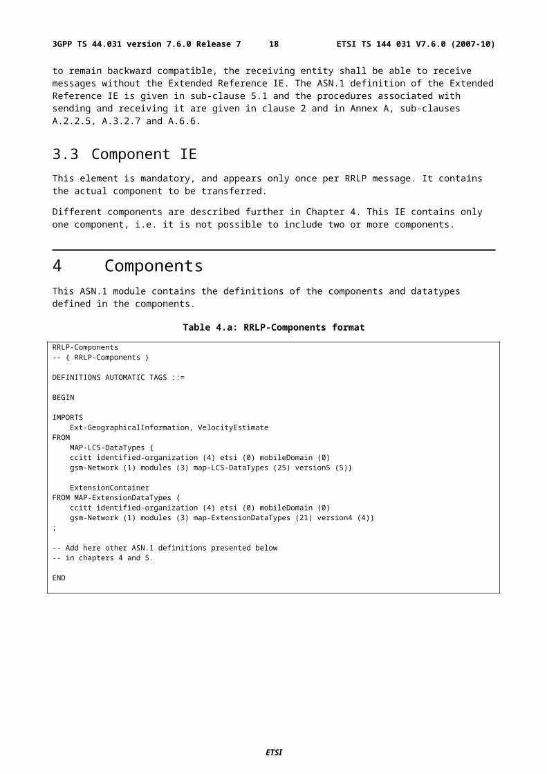
4 ComponentsThis ASN.1 module contains the definitions of the components and datatypes defined in the components.
Table 4.a: RRLP-Components format
RRLP-Components-- { RRLP-Components }
DEFINITIONS AUTOMATIC TAGS ::=
BEGIN
IMPORTSExt-GeographicalInformation, VelocityEstimate
FROMMAP-LCS-DataTypes {ccitt identified-organization (4) etsi (0) mobileDomain (0)gsm-Network (1) modules (3) map-LCS-DataTypes (25) version5 (5)}
ExtensionContainerFROM MAP-ExtensionDataTypes {
ccitt identified-organization (4) etsi (0) mobileDomain (0)gsm-Network (1) modules (3) map-ExtensionDataTypes (21) version4 (4)}
;
-- Add here other ASN.1 definitions presented below-- in chapters 4 and 5.
ETSI
ETSI TS 144 031 V7.6.0 (2007-10)143GPP TS 44.031 version 7.6.0 Release 7
END
4.1 Measure Position RequestThis component is used by the SMLC to request location measurements or a location estimate from the MS. It includes QoS, other instructions, and possible assistance data to the MS. This component is defined as follows:
Table 4.1.a: Measure Position Request
-- add this definition to RRLP-Components module
-- Measurement Position request componentMsrPosition-Req ::= SEQUENCE {
positionInstruct PositionInstruct,referenceAssistData ReferenceAssistData OPTIONAL,msrAssistData MsrAssistData OPTIONAL,systemInfoAssistData SystemInfoAssistData OPTIONAL,gps-AssistData GPS-AssistData OPTIONAL,extensionContainer ExtensionContainer OPTIONAL,...,-- Release 98 extension element
rel98-MsrPosition-Req-extension Rel98-MsrPosition-Req-Extension OPTIONAL,-- Release 5 extension element
rel5-MsrPosition-Req-extension Rel5-MsrPosition-Req-Extension OPTIONAL,-- Release 7 extension element
rel7-MsrPosition-Req-extension Rel7-MsrPosition-Req-Extension OPTIONAL}
The elements of this component are defined in clause 5.
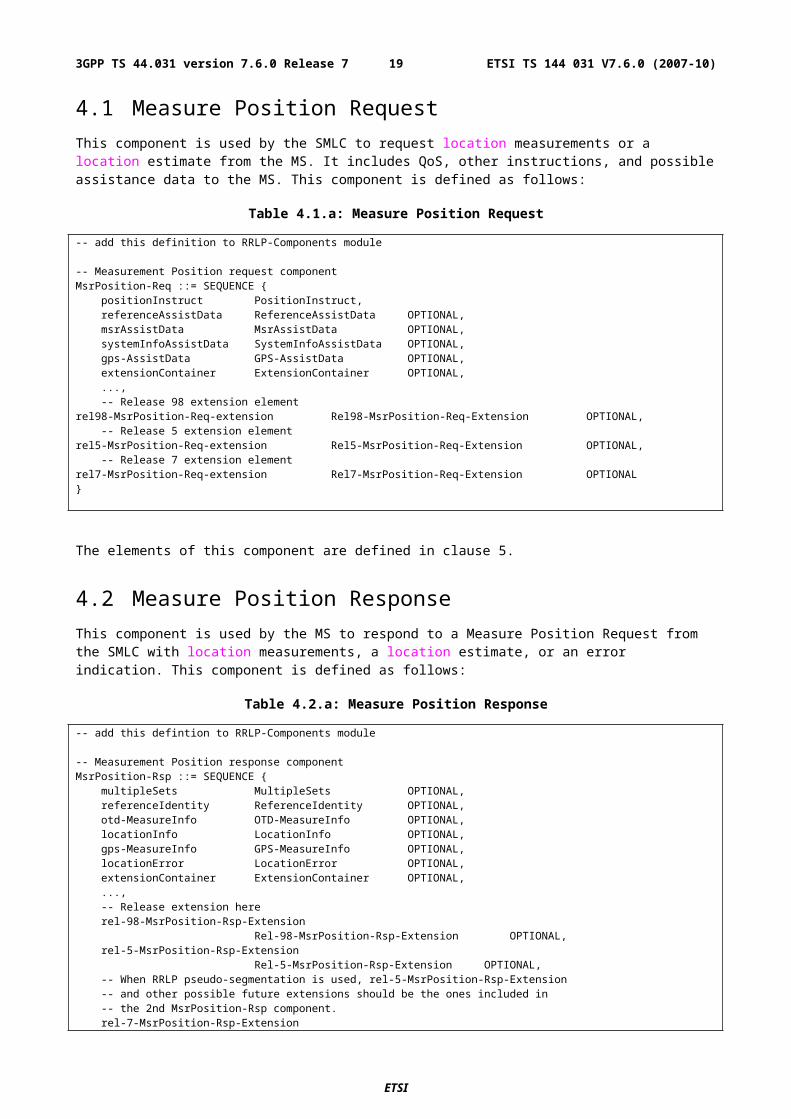
4.2 Measure Position ResponseThis component is used by the MS to respond to a Measure Position Request from the SMLC with location measurements, a location estimate, or an error indication. This component is defined as follows:
Table 4.2.a: Measure Position Response
-- add this defintion to RRLP-Components module
-- Measurement Position response componentMsrPosition-Rsp ::= SEQUENCE {
multipleSets MultipleSets OPTIONAL,referenceIdentity ReferenceIdentity OPTIONAL,otd-MeasureInfo OTD-MeasureInfo OPTIONAL,locationInfo LocationInfo OPTIONAL,gps-MeasureInfo GPS-MeasureInfo OPTIONAL,locationError LocationError OPTIONAL,extensionContainer ExtensionContainer OPTIONAL,...,-- Release extension hererel-98-MsrPosition-Rsp-Extension
Rel-98-MsrPosition-Rsp-Extension OPTIONAL,rel-5-MsrPosition-Rsp-Extension
Rel-5-MsrPosition-Rsp-Extension OPTIONAL,-- When RRLP pseudo-segmentation is used, rel-5-MsrPosition-Rsp-Extension -- and other possible future extensions should be the ones included in -- the 2nd MsrPosition-Rsp component.rel-7-MsrPosition-Rsp-Extension
Rel-7-MsrPosition-Rsp-Extension OPTIONAL}
The elements of this component are defined in clause 5.
ETSI
ETSI TS 144 031 V7.6.0 (2007-10)153GPP TS 44.031 version 7.6.0 Release 7
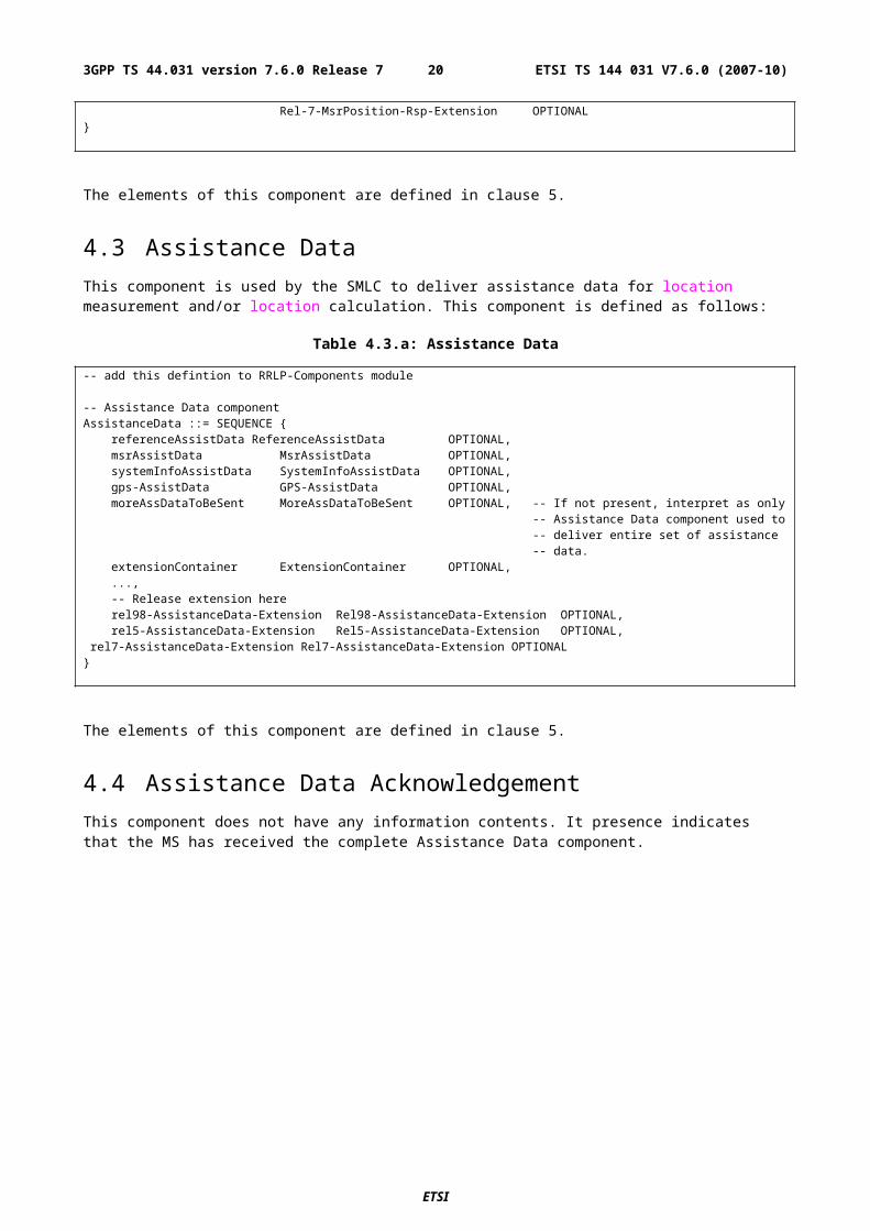
4.3 Assistance DataThis component is used by the SMLC to deliver assistance data for location measurement and/or location calculation. This component is defined as follows:
Table 4.3.a: Assistance Data
-- add this defintion to RRLP-Components module
-- Assistance Data componentAssistanceData ::= SEQUENCE {
referenceAssistData ReferenceAssistData OPTIONAL,msrAssistData MsrAssistData OPTIONAL,systemInfoAssistData SystemInfoAssistData OPTIONAL,gps-AssistData GPS-AssistData OPTIONAL,moreAssDataToBeSent MoreAssDataToBeSent OPTIONAL, -- If not present, interpret as only
-- Assistance Data component used to-- deliver entire set of assistance-- data.
extensionContainer ExtensionContainer OPTIONAL,...,-- Release extension hererel98-AssistanceData-Extension Rel98-AssistanceData-Extension OPTIONAL,rel5-AssistanceData-Extension Rel5-AssistanceData-Extension OPTIONAL,
rel7-AssistanceData-Extension Rel7-AssistanceData-Extension OPTIONAL}
The elements of this component are defined in clause 5.
4.4 Assistance Data AcknowledgementThis component does not have any information contents. It presence indicates that the MS has received the complete Assistance Data component.
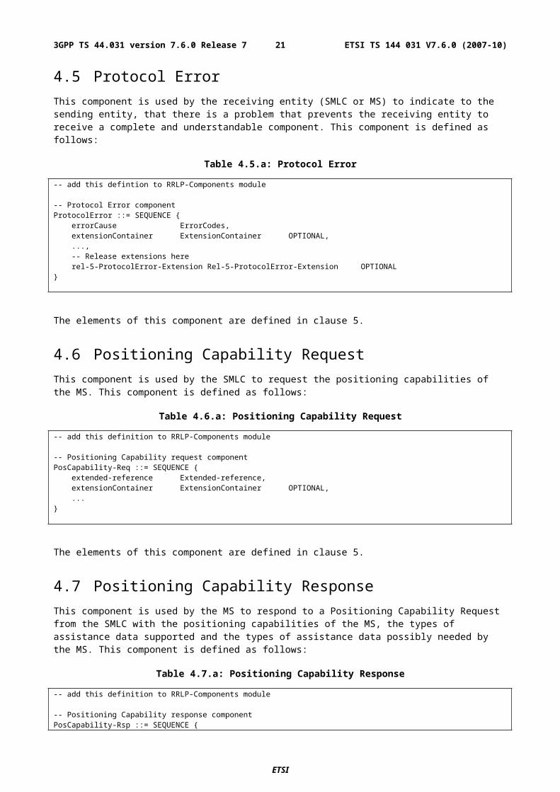
4.5 Protocol ErrorThis component is used by the receiving entity (SMLC or MS) to indicate to the sending entity, that there is a problem that prevents the receiving entity to receive a complete and understandable component. This component is defined as follows:
Table 4.5.a: Protocol Error
-- add this defintion to RRLP-Components module
-- Protocol Error componentProtocolError ::= SEQUENCE {
errorCause ErrorCodes,extensionContainer ExtensionContainer OPTIONAL,...,-- Release extensions hererel-5-ProtocolError-Extension Rel-5-ProtocolError-Extension OPTIONAL
}
The elements of this component are defined in clause 5.
ETSI
ETSI TS 144 031 V7.6.0 (2007-10)163GPP TS 44.031 version 7.6.0 Release 7
4.6 Positioning Capability Request This component is used by the SMLC to request the positioning capabilities of the MS. This component is defined as follows:
Table 4.6.a: Positioning Capability Request
-- add this definition to RRLP-Components module
-- Positioning Capability request componentPosCapability-Req ::= SEQUENCE {
extended-reference Extended-reference,extensionContainer ExtensionContainer OPTIONAL,...
}
The elements of this component are defined in clause 5.
4.7 Positioning Capability ResponseThis component is used by the MS to respond to a Positioning Capability Request from the SMLC with the positioning capabilities of the MS, the types of assistance data supported and the types of assistance data possibly needed by the MS. This component is defined as follows:
Table 4.7.a: Positioning Capability Response
-- add this definition to RRLP-Components module
-- Positioning Capability response componentPosCapability-Rsp ::= SEQUENCE {
extended-reference Extended-reference, posCapabilities PosCapabilities, assistanceSupported AssistanceSupported OPTIONAL, assistanceNeeded AssistanceNeeded OPTIONAL,
extensionContainer ExtensionContainer OPTIONAL,...
}
The elements of this component are defined in clause 5.
5 Elements of Components
5.1 ASN.1 DescriptionThe following ASN.1 code defines the elements of components. See the Annex A for further description of the contents of components and their elements.
Table 5.1.a: ASN.1 Description
-- add these defintions to RRLP-Components module-- Position instructionsPositionInstruct ::= SEQUENCE {
-- Method typemethodType MethodType,positionMethod PositionMethod,measureResponseTime MeasureResponseTime,useMultipleSets UseMultipleSets,environmentCharacter EnvironmentCharacter OPTIONAL
}
--
ETSI
ETSI TS 144 031 V7.6.0 (2007-10)173GPP TS 44.031 version 7.6.0 Release 7
MethodType ::= CHOICE {msAssisted AccuracyOpt, -- accuracy is optionalmsBased Accuracy, -- accuracy is mandatorymsBasedPref Accuracy, -- accuracy is mandatorymsAssistedPref Accuracy -- accuracy is mandatory
}
-- Accuracy of the location estimationAccuracyOpt ::= SEQUENCE {
accuracy Accuracy OPTIONAL}
-- The values of this field are defined in 3GPP TS 23.032 (Uncertainty code)Accuracy ::= INTEGER (0..127)
-- Position MethodPositionMethod ::= ENUMERATED {
eotd (0),gps (1),gpsOrEOTD (2)
}
-- Measurement request response timeMeasureResponseTime ::= INTEGER (0..7)
-- useMultiple Sets, FFS!UseMultipleSets ::= ENUMERATED {
multipleSets (0), -- multiple sets are allowedoneSet (1) -- sending of multiple is not allowed
}
-- Environment characterizationEnvironmentCharacter ::= ENUMERATED {
badArea (0), -- bad urban or suburban, heavy multipath and NLOSnotBadArea (1), -- light multipath and NLOSmixedArea (2), -- not defined or mixed environment...
}
-- E-OTD reference BTS for Assitance data IEReferenceAssistData ::= SEQUENCE {
bcchCarrier BCCHCarrier, -- BCCH carrierbsic BSIC, -- BSICtimeSlotScheme TimeSlotScheme, -- Timeslot schemebtsPosition BTSPosition OPTIONAL
}
-- ellipsoid point and-- ellipsoid point with altitude and uncertainty ellipsoid shapes are supportedBTSPosition ::= Ext-GeographicalInformation
-- RF channel number of BCCHBCCHCarrier ::= INTEGER (0..1023)
-- Base station Identity CodeBSIC ::= INTEGER (0..63)
-- Timeslot schemeTimeSlotScheme ::= ENUMERATED {
equalLength (0),variousLength (1)
}
-- Time slot (modulo)ModuloTimeSlot ::= INTEGER (0..3)
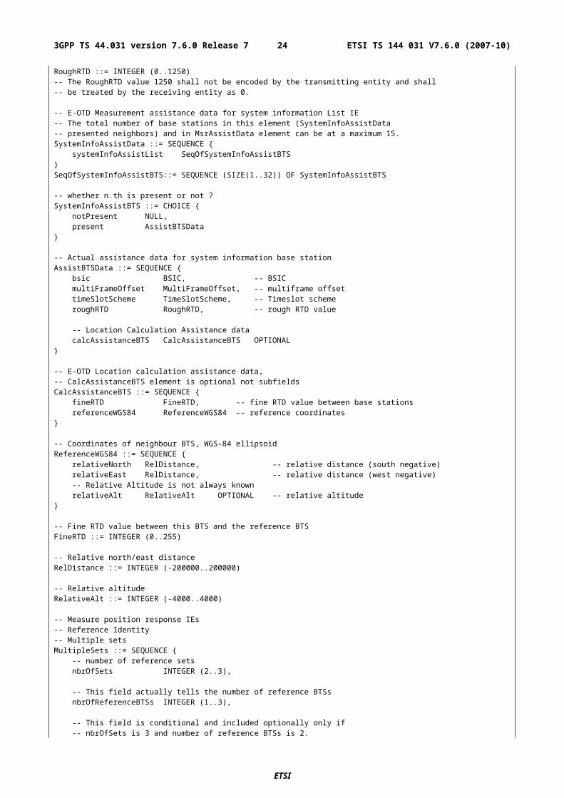
-- E-OTD measurement assistance data IE-- The total number of neighbors in this element (MsrAssistData)-- and in SystemInfoAssistData element (presented neighbors-- can be at a maximum 15!)MsrAssistData ::= SEQUENCE {
msrAssistList SeqOfMsrAssistBTS}SeqOfMsrAssistBTS ::= SEQUENCE (SIZE(1..15)) OF MsrAssistBTS
MsrAssistBTS ::= SEQUENCE {bcchCarrier BCCHCarrier, -- BCCH carrierbsic BSIC, -- BSIC
ETSI
ETSI TS 144 031 V7.6.0 (2007-10)183GPP TS 44.031 version 7.6.0 Release 7
multiFrameOffset MultiFrameOffset, -- multiframe offsettimeSlotScheme TimeSlotScheme, -- Timeslot schemeroughRTD RoughRTD, -- rough RTD value
-- Location Calculation Assistance data is moved herecalcAssistanceBTS CalcAssistanceBTS OPTIONAL
}
-- Multiframe offsetMultiFrameOffset ::= INTEGER (0..51)-- The Multiframe Offset value 51 shall not be encoded by the transmitting entity and-- shall be treated by the receiving entity as 0.
-- Rough RTD value between one base station and reference BTSRoughRTD ::= INTEGER (0..1250)-- The RoughRTD value 1250 shall not be encoded by the transmitting entity and shall-- be treated by the receiving entity as 0.
-- E-OTD Measurement assistance data for system information List IE-- The total number of base stations in this element (SystemInfoAssistData-- presented neighbors) and in MsrAssistData element can be at a maximum 15.SystemInfoAssistData ::= SEQUENCE {
systemInfoAssistList SeqOfSystemInfoAssistBTS}SeqOfSystemInfoAssistBTS::= SEQUENCE (SIZE(1..32)) OF SystemInfoAssistBTS
-- whether n.th is present or not ?SystemInfoAssistBTS ::= CHOICE {
notPresent NULL,present AssistBTSData
}
-- Actual assistance data for system information base stationAssistBTSData ::= SEQUENCE {
bsic BSIC, -- BSICmultiFrameOffset MultiFrameOffset, -- multiframe offsettimeSlotScheme TimeSlotScheme, -- Timeslot schemeroughRTD RoughRTD, -- rough RTD value
-- Location Calculation Assistance datacalcAssistanceBTS CalcAssistanceBTS OPTIONAL
}
-- E-OTD Location calculation assistance data,-- CalcAssistanceBTS element is optional not subfieldsCalcAssistanceBTS ::= SEQUENCE {
fineRTD FineRTD, -- fine RTD value between base stationsreferenceWGS84 ReferenceWGS84 -- reference coordinates
}
-- Coordinates of neighbour BTS, WGS-84 ellipsoidReferenceWGS84 ::= SEQUENCE {
relativeNorth RelDistance, -- relative distance (south negative)relativeEast RelDistance, -- relative distance (west negative)-- Relative Altitude is not always knownrelativeAlt RelativeAlt OPTIONAL -- relative altitude
}
-- Fine RTD value between this BTS and the reference BTSFineRTD ::= INTEGER (0..255)
-- Relative north/east distanceRelDistance ::= INTEGER (-200000..200000)
-- Relative altitudeRelativeAlt ::= INTEGER (-4000..4000)
-- Measure position response IEs-- Reference Identity-- Multiple setsMultipleSets ::= SEQUENCE {
-- number of reference setsnbrOfSets INTEGER (2..3),
-- This field actually tells the number of reference BTSsnbrOfReferenceBTSs INTEGER (1..3),
-- This field is conditional and included optionally only if
ETSI
ETSI TS 144 031 V7.6.0 (2007-10)193GPP TS 44.031 version 7.6.0 Release 7
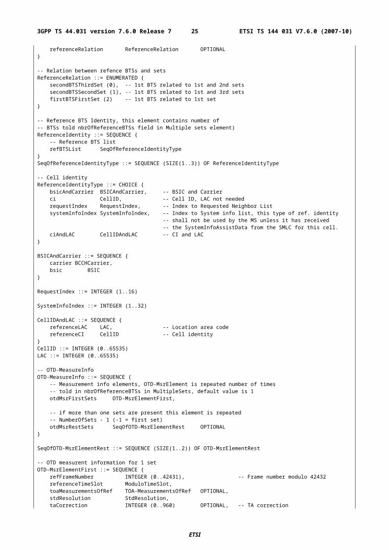
-- nbrOfSets is 3 and number of reference BTSs is 2.referenceRelation ReferenceRelation OPTIONAL
}
-- Relation between refence BTSs and setsReferenceRelation ::= ENUMERATED {
secondBTSThirdSet (0), -- 1st BTS related to 1st and 2nd setssecondBTSSecondSet (1), -- 1st BTS related to 1st and 3rd setsfirstBTSFirstSet (2) -- 1st BTS related to 1st set
}
-- Reference BTS Identity, this element contains number of-- BTSs told nbrOfReferenceBTSs field in Multiple sets element)ReferenceIdentity ::= SEQUENCE {
-- Reference BTS listrefBTSList SeqOfReferenceIdentityType
}SeqOfReferenceIdentityType ::= SEQUENCE (SIZE(1..3)) OF ReferenceIdentityType
-- Cell identityReferenceIdentityType ::= CHOICE {
bsicAndCarrier BSICAndCarrier, -- BSIC and Carrierci CellID, -- Cell ID, LAC not neededrequestIndex RequestIndex, -- Index to Requested Neighbor ListsystemInfoIndex SystemInfoIndex, -- Index to System info list, this type of ref. identity
-- shall not be used by the MS unless it has received-- the SystemInfoAssistData from the SMLC for this cell.
ciAndLAC CellIDAndLAC -- CI and LAC}
BSICAndCarrier ::= SEQUENCE {carrier BCCHCarrier,bsic BSIC
}
RequestIndex ::= INTEGER (1..16)
SystemInfoIndex ::= INTEGER (1..32)
CellIDAndLAC ::= SEQUENCE {referenceLAC LAC, -- Location area codereferenceCI CellID -- Cell identity
}CellID ::= INTEGER (0..65535)LAC ::= INTEGER (0..65535)
-- OTD-MeasureInfoOTD-MeasureInfo ::= SEQUENCE {
-- Measurement info elements, OTD-MsrElement is repeated number of times-- told in nbrOfReferenceBTSs in MultipleSets, default value is 1otdMsrFirstSets OTD-MsrElementFirst,
-- if more than one sets are present this element is repeated-- NumberOfSets - 1 (-1 = first set)otdMsrRestSets SeqOfOTD-MsrElementRest OPTIONAL
}
SeqOfOTD-MsrElementRest ::= SEQUENCE (SIZE(1..2)) OF OTD-MsrElementRest
-- OTD measurent information for 1 setOTD-MsrElementFirst ::= SEQUENCE {
refFrameNumber INTEGER (0..42431), -- Frame number modulo 42432referenceTimeSlot ModuloTimeSlot,toaMeasurementsOfRef TOA-MeasurementsOfRef OPTIONAL,stdResolution StdResolution,taCorrection INTEGER (0..960) OPTIONAL, -- TA correction
-- measured neighbors in OTD measurementsotd-FirstSetMsrs SeqOfOTD-FirstSetMsrs OPTIONAL
}SeqOfOTD-FirstSetMsrs ::= SEQUENCE (SIZE(1..10)) OF OTD-FirstSetMsrs
-- OTD measurent information 2 and 3 sets if existOTD-MsrElementRest ::= SEQUENCE {
refFrameNumber INTEGER (0..42431), -- Frame number modulo 42432referenceTimeSlot ModuloTimeSlot,toaMeasurementsOfRef TOA-MeasurementsOfRef OPTIONAL,stdResolution StdResolution,
ETSI
ETSI TS 144 031 V7.6.0 (2007-10)203GPP TS 44.031 version 7.6.0 Release 7
taCorrection INTEGER (0..960) OPTIONAL, -- TA correction
-- measured neighbors in OTD measurementsotd-MsrsOfOtherSets SeqOfOTD-MsrsOfOtherSets OPTIONAL
}SeqOfOTD-MsrsOfOtherSets ::= SEQUENCE (SIZE(1..10)) OF OTD-MsrsOfOtherSets
-- Standard deviation of the TOA measurements from the reference BTSTOA-MeasurementsOfRef ::= SEQUENCE {
refQuality RefQuality,numOfMeasurements NumOfMeasurements
}
RefQuality ::= INTEGER (0..31) -- St Dev of TOA of reference as defined in annexNumOfMeasurements ::= INTEGER (0..7) -- No. of measurements for RefQuality as defined in annexStdResolution ::= INTEGER (0..3) -- Values of resolution are defined in annex
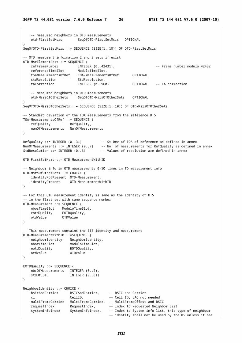
OTD-FirstSetMsrs ::= OTD-MeasurementWithID
-- Neighbour info in OTD measurements 0-10 times in TD measurement infoOTD-MsrsOfOtherSets ::= CHOICE {
identityNotPresent OTD-Measurement,identityPresent OTD-MeasurementWithID
}
-- For this OTD measurement identity is same as the identity of BTS-- in the first set with same sequence numberOTD-Measurement ::= SEQUENCE {
nborTimeSlot ModuloTimeSlot,eotdQuality EOTDQuality,otdValue OTDValue
}
-- This measurement contains the BTS identity and measurementOTD-MeasurementWithID ::=SEQUENCE {
neighborIdentity NeighborIdentity,nborTimeSlot ModuloTimeSlot,eotdQuality EOTDQuality,otdValue OTDValue
}
EOTDQuality ::= SEQUENCE {nbrOfMeasurements INTEGER (0..7),stdOfEOTD INTEGER (0..31)
}
NeighborIdentity ::= CHOICE {bsicAndCarrier BSICAndCarrier, -- BSIC and Carrierci CellID, -- Cell ID, LAC not neededmultiFrameCarrier MultiFrameCarrier, -- MultiFrameOffest and BSICrequestIndex RequestIndex, -- Index to Requested Neighbor ListsystemInfoIndex SystemInfoIndex, -- Index to System info list, this type of neighbour
-- identity shall not be used by the MS unless it has-- received the SystemInfoAssistData from the SMLC for-- this cell.
ciAndLAC CellIDAndLAC -- CI and LAC}
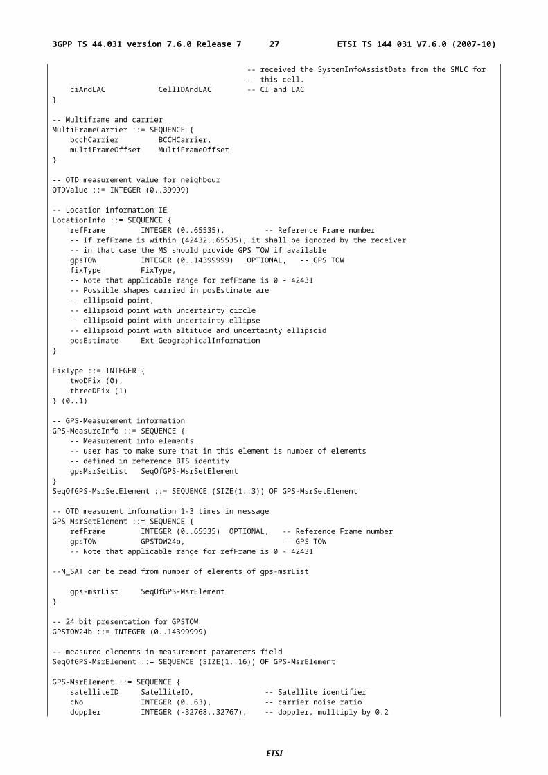
-- Multiframe and carrierMultiFrameCarrier ::= SEQUENCE {
bcchCarrier BCCHCarrier,multiFrameOffset MultiFrameOffset
}
-- OTD measurement value for neighbourOTDValue ::= INTEGER (0..39999)
-- Location information IELocationInfo ::= SEQUENCE {
refFrame INTEGER (0..65535), -- Reference Frame number-- If refFrame is within (42432..65535), it shall be ignored by the receiver-- in that case the MS should provide GPS TOW if availablegpsTOW INTEGER (0..14399999) OPTIONAL, -- GPS TOWfixType FixType,-- Note that applicable range for refFrame is 0 - 42431-- Possible shapes carried in posEstimate are-- ellipsoid point,-- ellipsoid point with uncertainty circle
ETSI
ETSI TS 144 031 V7.6.0 (2007-10)213GPP TS 44.031 version 7.6.0 Release 7
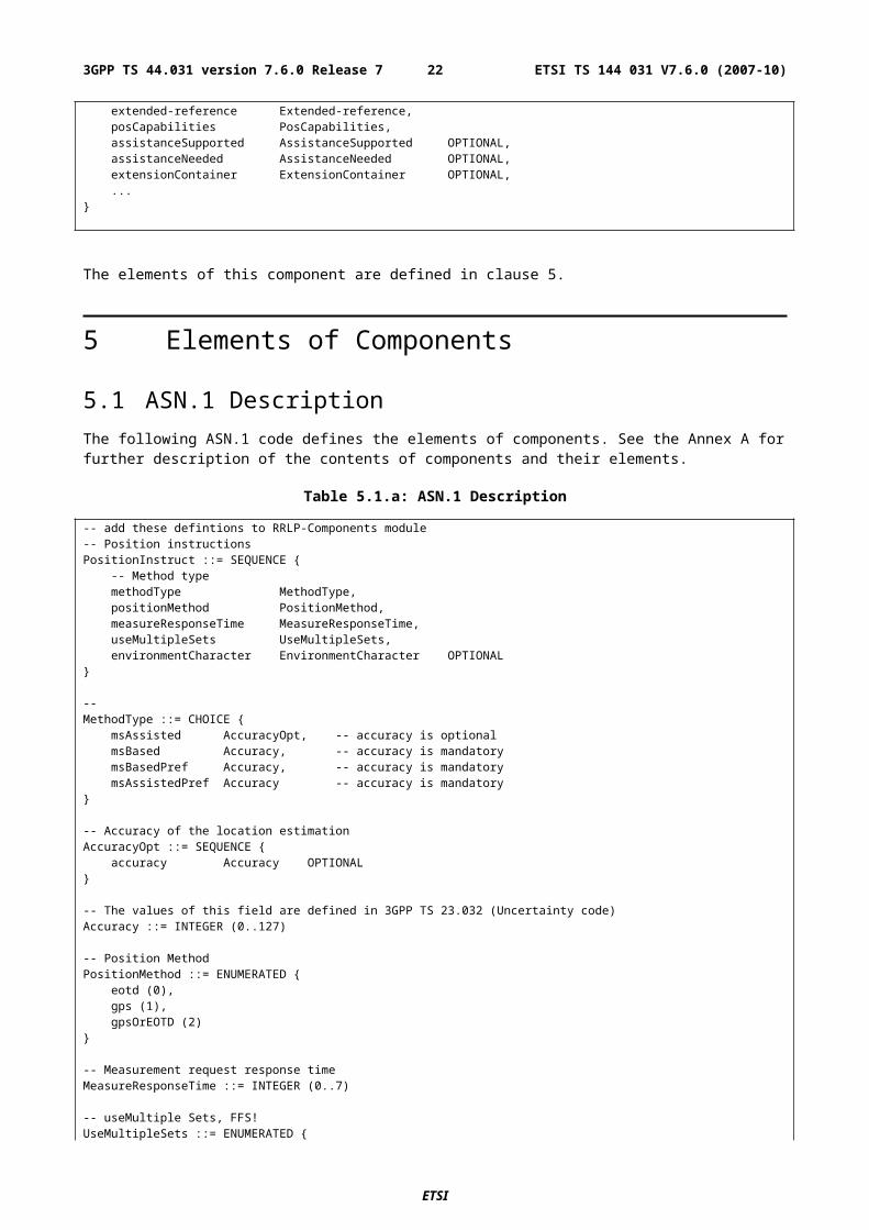
-- ellipsoid point with uncertainty ellipse-- ellipsoid point with altitude and uncertainty ellipsoidposEstimate Ext-GeographicalInformation
}
FixType ::= INTEGER {twoDFix (0),threeDFix (1)
} (0..1)
-- GPS-Measurement informationGPS-MeasureInfo ::= SEQUENCE {
-- Measurement info elements-- user has to make sure that in this element is number of elements-- defined in reference BTS identitygpsMsrSetList SeqOfGPS-MsrSetElement
}SeqOfGPS-MsrSetElement ::= SEQUENCE (SIZE(1..3)) OF GPS-MsrSetElement
-- OTD measurent information 1-3 times in messageGPS-MsrSetElement ::= SEQUENCE {
refFrame INTEGER (0..65535) OPTIONAL, -- Reference Frame numbergpsTOW GPSTOW24b, -- GPS TOW-- Note that applicable range for refFrame is 0 - 42431
--N_SAT can be read from number of elements of gps-msrList
gps-msrList SeqOfGPS-MsrElement}
-- 24 bit presentation for GPSTOWGPSTOW24b ::= INTEGER (0..14399999)
-- measured elements in measurement parameters fieldSeqOfGPS-MsrElement ::= SEQUENCE (SIZE(1..16)) OF GPS-MsrElement
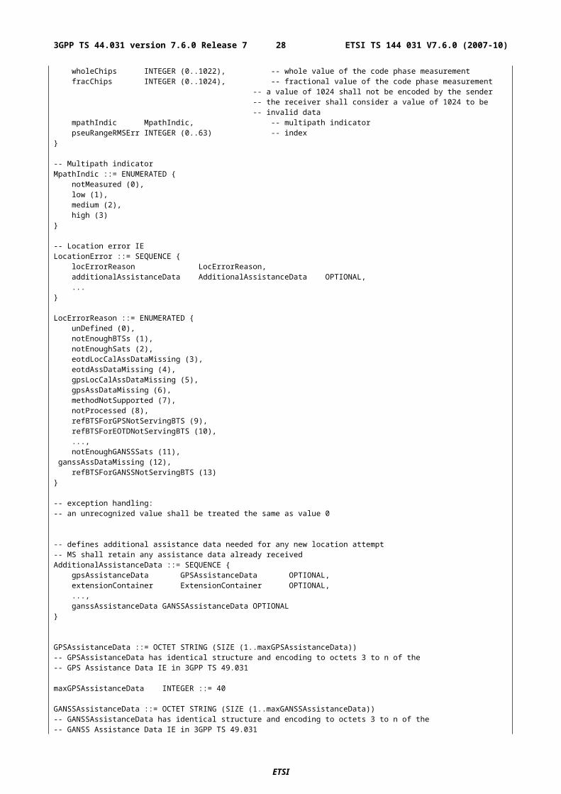
GPS-MsrElement ::= SEQUENCE {satelliteID SatelliteID, -- Satellite identifiercNo INTEGER (0..63), -- carrier noise ratiodoppler INTEGER (-32768..32767), -- doppler, mulltiply by 0.2wholeChips INTEGER (0..1022), -- whole value of the code phase measurementfracChips INTEGER (0..1024), -- fractional value of the code phase measurement
-- a value of 1024 shall not be encoded by the sender-- the receiver shall consider a value of 1024 to be-- invalid data
mpathIndic MpathIndic, -- multipath indicatorpseuRangeRMSErr INTEGER (0..63) -- index
}
-- Multipath indicatorMpathIndic ::= ENUMERATED {
notMeasured (0),low (1),medium (2),high (3)
}
-- Location error IELocationError ::= SEQUENCE {
locErrorReason LocErrorReason,additionalAssistanceData AdditionalAssistanceData OPTIONAL,...
}
LocErrorReason ::= ENUMERATED {unDefined (0),notEnoughBTSs (1),notEnoughSats (2),eotdLocCalAssDataMissing (3),eotdAssDataMissing (4),gpsLocCalAssDataMissing (5),gpsAssDataMissing (6),methodNotSupported (7),notProcessed (8),refBTSForGPSNotServingBTS (9),refBTSForEOTDNotServingBTS (10),...,notEnoughGANSSSats (11),
ETSI
ETSI TS 144 031 V7.6.0 (2007-10)223GPP TS 44.031 version 7.6.0 Release 7
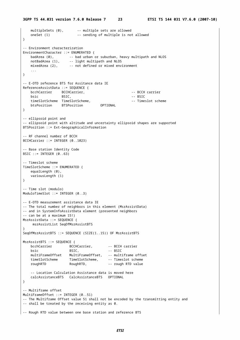
ganssAssDataMissing (12),refBTSForGANSSNotServingBTS (13)
}
-- exception handling:-- an unrecognized value shall be treated the same as value 0
-- defines additional assistance data needed for any new location attempt-- MS shall retain any assistance data already receivedAdditionalAssistanceData ::= SEQUENCE {
gpsAssistanceData GPSAssistanceData OPTIONAL,extensionContainer ExtensionContainer OPTIONAL,...,ganssAssistanceData GANSSAssistanceData OPTIONAL
}
GPSAssistanceData ::= OCTET STRING (SIZE (1..maxGPSAssistanceData))-- GPSAssistanceData has identical structure and encoding to octets 3 to n of the-- GPS Assistance Data IE in 3GPP TS 49.031
maxGPSAssistanceData INTEGER ::= 40
GANSSAssistanceData ::= OCTET STRING (SIZE (1..maxGANSSAssistanceData))-- GANSSAssistanceData has identical structure and encoding to octets 3 to n of the-- GANSS Assistance Data IE in 3GPP TS 49.031
maxGANSSAssistanceData INTEGER ::= 40
-- Protocol Error CausesErrorCodes ::= ENUMERATED {
unDefined (0),missingComponet (1),incorrectData (2),missingIEorComponentElement (3),messageTooShort (4),unknowReferenceNumber (5),...}
-- exception handling:-- an unrecognized value shall be treated the same as value 0
-- GPS assistance data IEGPS-AssistData ::= SEQUENCE {
controlHeader ControlHeader}
-- More Assistance Data To Be Sent IE-- More Assistance Data Components On the Way indication for delivery of an entire set of assistance-- data in multiple Assistance Data components.
MoreAssDataToBeSent ::= ENUMERATED {noMoreMessages (0), -- This is the only or last Assistance Data message used to deliver
-- the entire set of assistance data.moreMessagesOnTheWay (1) -- The SMLC will send more Assistance Data messages or a final RRLP
-- Measure Position Request message to deliver the-- the entire set of assistance data.
}
-- Control header of the GPS assistance dataControlHeader ::= SEQUENCE {
-- Field type Present informationreferenceTime ReferenceTime OPTIONAL,refLocation RefLocation OPTIONAL,dgpsCorrections DGPSCorrections OPTIONAL,navigationModel NavigationModel OPTIONAL,ionosphericModel IonosphericModel OPTIONAL,utcModel UTCModel OPTIONAL,almanac Almanac OPTIONAL,acquisAssist AcquisAssist OPTIONAL,realTimeIntegrity SeqOf-BadSatelliteSet OPTIONAL
}
ReferenceTime ::= SEQUENCE {gpsTime GPSTime,
ETSI
ETSI TS 144 031 V7.6.0 (2007-10)233GPP TS 44.031 version 7.6.0 Release 7
gsmTime GSMTime OPTIONAL,gpsTowAssist GPSTOWAssist OPTIONAL
}
-- GPS Time includes week number and time-of-week (TOW)GPSTime ::= SEQUENCE {
gpsTOW23b GPSTOW23b,gpsWeek GPSWeek
}
-- GPSTOW, range 0-604799.92, resolution 0.08 sec, 23-bit presentationGPSTOW23b ::= INTEGER (0..7559999)
-- GPS week numberGPSWeek ::= INTEGER (0..1023)
-- GPSTOWAssist consists of TLM message, Anti-spoof flag, Alert flag, and 2 reserved bits in TLM Word-- for each visible satellite.-- N_SAT can be read from number of elements in GPSTOWAssistGPSTOWAssist ::= SEQUENCE (SIZE(1..12)) OF GPSTOWAssistElement
GPSTOWAssistElement ::= SEQUENCE {satelliteID SatelliteID,tlmWord TLMWord,antiSpoof AntiSpoofFlag,alert AlertFlag,tlmRsvdBits TLMReservedBits
}
-- TLM Word, 14 bitsTLMWord ::= INTEGER (0..16383)
-- Anti-Spoof flagAntiSpoofFlag ::= INTEGER (0..1)
-- Alert flagAlertFlag ::= INTEGER (0..1)
-- Reserved bits in TLM word, MSB occurs earlier in TLM Word transmitted by satelliteTLMReservedBits ::= INTEGER (0..3)
GSMTime ::= SEQUENCE {bcchCarrier BCCHCarrier, -- BCCH carrierbsic BSIC, -- BSICframeNumber FrameNumber,timeSlot TimeSlot,bitNumber BitNumber
}
-- Frame numberFrameNumber ::= INTEGER (0..2097151)
-- Time slot numberTimeSlot ::= INTEGER (0..7)
-- Bit numberBitNumber ::= INTEGER (0..156)
-- Reference Location IERefLocation ::= SEQUENCE {
threeDLocation Ext-GeographicalInformation}
-- DGPS Corrections IEDGPSCorrections ::= SEQUENCE {
gpsTOW INTEGER (0..604799), -- DGPS reference timestatus INTEGER (0..7),-- N_SAT can be read from number of elements of satListsatList SeqOfSatElement
}SeqOfSatElement ::= SEQUENCE (SIZE (1..16)) OF SatElement
-- number of correction for satellitesSatElement ::= SEQUENCE {
satelliteID SatelliteID,
ETSI
ETSI TS 144 031 V7.6.0 (2007-10)243GPP TS 44.031 version 7.6.0 Release 7
--- Sequence number for ephemerisiode INTEGER (0..239),-- User Differential Range Errorudre INTEGER (0..3),
-- Pseudo Range Correction, range is-- -655.04 - +655.04,pseudoRangeCor INTEGER (-2047..2047),
-- Pseudo Range Rate Correction, range is-- -4.064 - +4.064,rangeRateCor INTEGER (-127..127),
-- Delta Pseudo Range Correction 2 deltaPseudoRangeCor2 INTEGER (-127..127), -- This IE shall be ignored by the receiver and
-- set to zero by the sender-- Delta Pseudo Range Correction 2deltaRangeRateCor2 INTEGER (-7..7), -- This IE shall be ignored by the receiver and
-- set to zero by the sender-- Delta Pseudo Range Correction 3deltaPseudoRangeCor3 INTEGER (-127..127), -- This IE shall be ignored by the receiver and
-- set to zero by the sender-- Delta Pseudo Range Correction 3deltaRangeRateCor3 INTEGER (-7..7) -- This IE shall be ignored by the receiver and
-- set to zero by the sender}
SatelliteID ::= INTEGER (0..63) -- identifies satellite
-- Navigation Model IENavigationModel ::= SEQUENCE {
navModelList SeqOfNavModelElement}
-- navigation model satellite listSeqOfNavModelElement ::= SEQUENCE (SIZE(1..16)) OF NavModelElement
NavModelElement ::= SEQUENCE {satelliteID SatelliteID,satStatus SatStatus -- satellite status
}
-- the Status of the navigation modelSatStatus ::= CHOICE {
-- New satellite, new Navigation ModelnewSatelliteAndModelUC UncompressedEphemeris,
-- Existing satellite, Existing Navigation ModeloldSatelliteAndModel NULL,
-- Existing satellite, new Navigation ModelnewNaviModelUC UncompressedEphemeris,...
}
-- Uncompressed satellite emhemeris and clock correctionsUncompressedEphemeris ::= SEQUENCE {
ephemCodeOnL2 INTEGER (0..3),ephemURA INTEGER (0..15),ephemSVhealth INTEGER (0..63),ephemIODC INTEGER (0..1023),ephemL2Pflag INTEGER (0..1),ephemSF1Rsvd EphemerisSubframe1Reserved,ephemTgd INTEGER (-128..127),ephemToc INTEGER (0..37799),ephemAF2 INTEGER (-128..127),ephemAF1 INTEGER (-32768..32767),ephemAF0 INTEGER (-2097152..2097151),ephemCrs INTEGER (-32768..32767),ephemDeltaN INTEGER (-32768..32767),ephemM0 INTEGER (-2147483648..2147483647),ephemCuc INTEGER (-32768..32767),ephemE INTEGER (0..4294967295),ephemCus INTEGER (-32768..32767),ephemAPowerHalf INTEGER (0..4294967295),ephemToe INTEGER (0..37799),ephemFitFlag INTEGER (0..1),
ETSI
ETSI TS 144 031 V7.6.0 (2007-10)253GPP TS 44.031 version 7.6.0 Release 7
ephemAODA INTEGER (0..31),ephemCic INTEGER (-32768..32767),ephemOmegaA0 INTEGER (-2147483648..2147483647),ephemCis INTEGER (-32768..32767),ephemI0 INTEGER (-2147483648..2147483647),ephemCrc INTEGER (-32768..32767),ephemW INTEGER (-2147483648..2147483647),ephemOmegaADot INTEGER (-8388608..8388607),ephemIDot INTEGER (-8192..8191)
}
-- Reserved bits in subframe 1 of navigation messageEphemerisSubframe1Reserved ::= SEQUENCE {
reserved1 INTEGER (0..8388607), -- 23-bit fieldreserved2 INTEGER (0..16777215), -- 24-bit fieldreserved3 INTEGER (0..16777215), -- 24-bit fieldreserved4 INTEGER (0..65535) -- 16-bit field
}
-- Ionospheric Model IEIonosphericModel ::= SEQUENCE {
alfa0 INTEGER (-128..127),alfa1 INTEGER (-128..127),alfa2 INTEGER (-128..127),alfa3 INTEGER (-128..127),beta0 INTEGER (-128..127),beta1 INTEGER (-128..127),beta2 INTEGER (-128..127),beta3 INTEGER (-128..127)
}
-- Universal Time Coordinate ModelUTCModel ::= SEQUENCE {
utcA1 INTEGER (-8388608..8388607),utcA0 INTEGER (-2147483648..2147483647),utcTot INTEGER (0..255),utcWNt INTEGER (0..255),utcDeltaTls INTEGER (-128..127),utcWNlsf INTEGER (0..255),utcDN INTEGER (-128..127),utcDeltaTlsf INTEGER (-128..127)
}
-- Almanac, Long term model-- NOTE: These are parameters are subset of the ephemeris-- NOTE: But with reduced resolution and accuracyAlmanac ::= SEQUENCE {
alamanacWNa INTEGER (0..255), -- Once per message
-- navigation model satellite list.-- The size of almanacList is actually Nums_Sats_Total fieldalmanacList SeqOfAlmanacElement
}SeqOfAlmanacElement ::= SEQUENCE (SIZE(1..64)) OF AlmanacElement
-- Almanac info once per satelliteAlmanacElement ::= SEQUENCE {
satelliteID SatelliteID,almanacE INTEGER (0..65535),alamanacToa INTEGER (0..255),almanacKsii INTEGER (-32768..32767),almanacOmegaDot INTEGER (-32768..32767),almanacSVhealth INTEGER (0..255),almanacAPowerHalf INTEGER (0..16777215),almanacOmega0 INTEGER (-8388608..8388607),almanacW INTEGER (-8388608..8388607),almanacM0 INTEGER (-8388608..8388607),almanacAF0 INTEGER (-1024..1023),almanacAF1 INTEGER (-1024..1023)
}
-- Acquisition AssistanceAcquisAssist ::= SEQUENCE {
-- Number of Satellites can be read from acquistListtimeRelation TimeRelation,
-- Acquisition assistance list
ETSI
ETSI TS 144 031 V7.6.0 (2007-10)263GPP TS 44.031 version 7.6.0 Release 7
-- The size of Number of Satellites is actually Number of Satellites fieldacquisList SeqOfAcquisElement
}SeqOfAcquisElement ::= SEQUENCE (SIZE(1..16)) OF AcquisElement
-- the relationship between GPS time and air-interface timingTimeRelation ::= SEQUENCE {
--gpsTOW GPSTOW23b, -- 23b presentationgsmTime GSMTime OPTIONAL
}
-- data occuring per number of satellitesAcquisElement ::= SEQUENCE {
svid SatelliteID,
-- Doppler 0th order term,-- -5120.0 - 5117.5 Hz (= -2048 - 2047 with 2.5 Hz resolution)doppler0 INTEGER (-2048..2047),addionalDoppler AddionalDopplerFields OPTIONAL,codePhase INTEGER (0..1022), -- Code PhaseintCodePhase INTEGER (0..19), -- Integer Code PhasegpsBitNumber INTEGER (0..3), -- GPS bit numbercodePhaseSearchWindow INTEGER (0..15), -- Code Phase Search WindowaddionalAngle AddionalAngleFields OPTIONAL
}
AddionalDopplerFields ::= SEQUENCE {-- Doppler 1st order term, -1.0 - +0.5 Hz/sec
-- (= -42 + (0 to 63) with 1/42 Hz/sec. resolution)doppler1 INTEGER (0..63),dopplerUncertainty INTEGER (0..7)
-- a sender shall not encode any DopplerUncertainty value in the range 5 to 7 -- a receiver shall ignore any value between 5 and 7.}
AddionalAngleFields ::= SEQUENCE {-- azimuth angle, 0 - 348.75 deg (= 0 - 31 with 11.25 deg resolution)azimuth INTEGER (0..31),-- elevation angle, 0 - 78.75 deg (= 0 - 7 with 11.25 deg resolution)elevation INTEGER (0..7)
}
-- Real-Time Integrity-- number of bad satellites can be read from this elementSeqOf-BadSatelliteSet ::= SEQUENCE (SIZE(1..16)) OF SatelliteID
-- Extension Elements
-- Release 98 Extensions hereRel98-MsrPosition-Req-Extension ::= SEQUENCE {
rel98-Ext-ExpOTD Rel98-Ext-ExpOTD OPTIONAL, -- ExpectedOTD extension...,
gpsTimeAssistanceMeasurementRequest NULL OPTIONAL, gpsReferenceTimeUncertainty GPSReferenceTimeUncertainty OPTIONAL
-- Further R98 extensions here}Rel98-AssistanceData-Extension ::= SEQUENCE {
rel98-Ext-ExpOTD Rel98-Ext-ExpOTD OPTIONAL, -- ExpectedOTD extension...,
gpsTimeAssistanceMeasurementRequest NULL OPTIONAL, gpsReferenceTimeUncertainty GPSReferenceTimeUncertainty OPTIONAL
-- Further R98 extensions here}
-- Release 98 ExpOTD extensionRel98-Ext-ExpOTD ::= SEQUENCE {-- If MsrAssistBTS is included in message, msrAssistData-R98-ExpOTD shall be included.
msrAssistData-R98-ExpOTD MsrAssistData-R98-ExpOTD OPTIONAL,
-- If SystemInfoAssistaData is included in message, systemInfoAssistData-R98-ExpOTD shall be-- included.
systemInfoAssistData-R98-ExpOTD SystemInfoAssistData-R98-ExpOTD OPTIONAL}
-- MsrAssistData R98 extension
ETSI
ETSI TS 144 031 V7.6.0 (2007-10)273GPP TS 44.031 version 7.6.0 Release 7
MsrAssistData-R98-ExpOTD ::= SEQUENCE { msrAssistList-R98-ExpOTD SeqOfMsrAssistBTS-R98-ExpOTD
}
-- Indexes in SeqOfMsrAssistBTS-R98-ExpOTD refer to SeqOfMsrAssistBTS-- If the index exceeds the SegOfMsrAssistBTS range or if there is other-- inconsistencies between the BTS indices, the MS shall apply protocol-- error cause incorrectDataSeqOfMsrAssistBTS-R98-ExpOTD ::= SEQUENCE (SIZE(1..15)) OF MsrAssistBTS-R98-ExpOTD
-- This element completes MsrAssistBTS IEMsrAssistBTS-R98-ExpOTD ::= SEQUENCE {
expectedOTD ExpectedOTD,expOTDUncertainty ExpOTDUncertainty
}
-- SystemInfoAssistData R98 extensionSystemInfoAssistData-R98-ExpOTD ::= SEQUENCE {
systemInfoAssistListR98-ExpOTD SeqOfSystemInfoAssistBTS-R98-ExpOTD}
-- SeqOfSystemInfoAssistBTS-R98-ExpOTD index refer to SeqOfSystemInfoAssistBTS-- If the index exceeds the SegOfSystemInfoAssistBTS range or if there is other-- inconsistencies between the BTS indices, the MS shall apply protocol-- error cause incorrectDataSeqOfSystemInfoAssistBTS-R98-ExpOTD ::= SEQUENCE (SIZE(1..32)) OF SystemInfoAssistBTS-R98-ExpOTD
-- whether n.th is present or not ?SystemInfoAssistBTS-R98-ExpOTD ::= CHOICE {
notPresent NULL,present AssistBTSData-R98-ExpOTD
}
-- This element completes AssistBTSData IEAssistBTSData-R98-ExpOTD ::= SEQUENCE {
expectedOTD ExpectedOTD,expOTDuncertainty ExpOTDUncertainty -- Uncertainty of expected OTD
}
-- Expected OTD value between nbor base station and reference BTS-- at MS's current estimated location.ExpectedOTD ::= INTEGER (0..1250)-- The ExpectedOTD value 1250 shall not be encoded by the transmitting entity and-- shall be treated by the receiving entity as 0.-- Uncertainty of Exptected OTD in bitsExpOTDUncertainty ::= INTEGER(0..7)
-- Release 98 extensions
GPSReferenceTimeUncertainty ::= INTEGER (0 .. 127) -- Coding according to Annex
GPSTimeAssistanceMeasurements ::= SEQUENCE { referenceFrameMSB INTEGER (0 .. 63) OPTIONAL, -- MSB of frame number gpsTowSubms INTEGER (0 .. 9999) OPTIONAL, -- in units of 100ns, for MS based AGPS deltaTow INTEGER (0 .. 127) OPTIONAL, -- for MS assisted AGPS gpsReferenceTimeUncertainty GPSReferenceTimeUncertainty OPTIONAL}
Rel-98-MsrPosition-Rsp-Extension ::= SEQUENCE {
-- First extension to Release 98rel-98-Ext-MeasureInfo SEQUENCE {
otd-MeasureInfo-R98-Ext OTD-MeasureInfo-R98-Ext OPTIONAL},...,
timeAssistanceMeasurements GPSTimeAssistanceMeasurements OPTIONAL -- Further R98 extensions here}
-- This is an addition to OTD-MeasureInfo element defined in original message,-- If OTD-MeasureInfo is absent, or if one or more OTD-MsrElementRest are present-- OTD-MeasureInfo-R98-Ext shall be absent.-- OTD-MeasureInfo-R98-ExtOTD-MeasureInfo-R98-Ext ::= SEQUENCE {
-- Measurement info elementsotdMsrFirstSets-R98-Ext OTD-MsrElementFirst-R98-Ext
}
ETSI
ETSI TS 144 031 V7.6.0 (2007-10)283GPP TS 44.031 version 7.6.0 Release 7
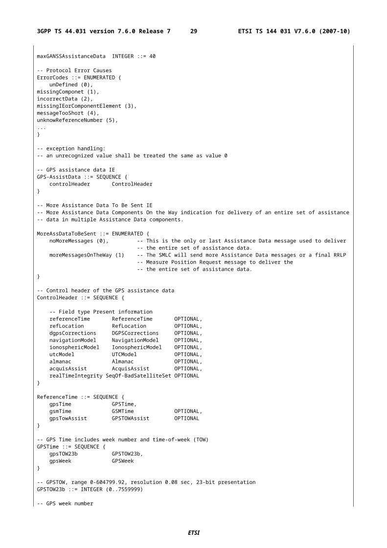
-- OTD measurement information Ext for the first set onlyOTD-MsrElementFirst-R98-Ext ::= SEQUENCE {
-- additional measured neighbors in OTD measurementsotd-FirstSetMsrs-R98-Ext SeqOfOTD-FirstSetMsrs-R98-Ext OPTIONAL
}SeqOfOTD-FirstSetMsrs-R98-Ext ::= SEQUENCE (SIZE(1..5)) OF OTD-FirstSetMsrs
Rel-5-MsrPosition-Rsp-Extension ::= SEQUENCE {
extended-reference Extended-reference OPTIONAL,-- The extended-reference shall be included by the MS if and only if previously-- received from the SMLC in a Measure Position Request. When included, the value sent-- by the MS shall equal the value received from the SMLC.
-- extension to Release 5, for RRLP pseudo-segmentation hereotd-MeasureInfo-5-Ext OTD-MeasureInfo-5-Ext OPTIONAL,ulPseudoSegInd UlPseudoSegInd OPTIONAL, -- Included when uplink RRLP-- Pseudo-segmentation is used, not included when no uplink pseudo-segmentation is used...
-- Possibly more extensions for Release 5 here later}
Extended-reference ::= SEQUENCE {smlc-code INTEGER (0..63),transaction-ID INTEGER (0..262143)
}
OTD-MeasureInfo-5-Ext ::= SeqOfOTD-MsrElementRest-- if more than one measurement sets are present this element is repeated-- NumberOfSets - 1 (-1 = first set) combined in OTD-MeasureInfo-5-Ext and-- OTD-MeasureInfo (e.g. if NumberOfSets is 3, then one otdMsrRestSets may-- be sent in OTD-MeasureInfo-5-Ext and one in OTD-MeasureInfo)
-- First part of Uplink RRLP Pseudo-segmentation indication, possibly more may be defined-- in the future for segmentation with more than two segments.UlPseudoSegInd ::= ENUMERATED {
firstOfMany (0),secondOfMany(1)
}
Rel5-MsrPosition-Req-Extension ::= SEQUENCE {extended-reference Extended-reference,...-- Possibly more extensions for Release 5 here later
}
Rel5-AssistanceData-Extension ::= SEQUENCE {extended-reference Extended-reference,...
-- Possibly more extensions for Release 5 here later}
Rel-5-ProtocolError-Extension::= SEQUENCE {extended-reference Extended-reference OPTIONAL,-- The extended-reference shall be included by the MS if and only if previously-- received from the SMLC.-- When included, the value sent by the MS shall equal the value received from the SMLC....
-- Possibly more extensions for Release 5 here later}
-- Release 7 Extensions here
Rel7-MsrPosition-Req-Extension ::= SEQUENCE {velocityRequested NULL OPTIONAL,
ganssPositionMethod GANSSPositioningMethod OPTIONAL, ganss-AssistData GANSS-AssistData OPTIONAL, ganssCarrierPhaseMeasurementRequest NULL OPTIONAL, ganssTODGSMTimeAssociationMeasurementRequest NULL OPTIONAL,
requiredResponseTime RequiredResponseTime OPTIONAL,...-- Further Release 7 extentions here
}
-- additional satellite systems may be added in future versions of the protocolGANSSPositioningMethod ::= BIT STRING {
ETSI
ETSI TS 144 031 V7.6.0 (2007-10)293GPP TS 44.031 version 7.6.0 Release 7
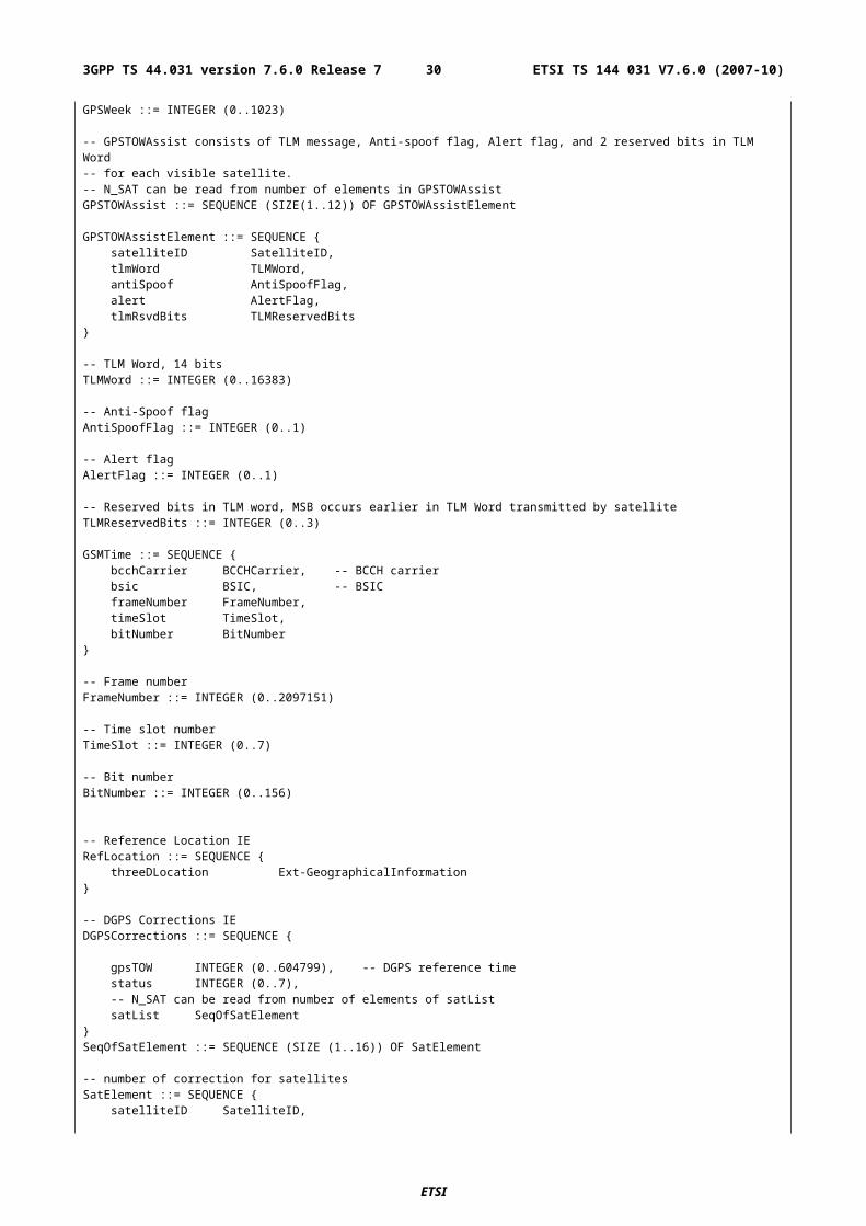
gps (0),galileo (1)} (SIZE (2..16))
GANSS-AssistData ::= SEQUENCE {ganss-controlHeader GANSS-ControlHeader
}GANSS-ControlHeader ::= SEQUENCE { ganssCommonAssistData GANSSCommonAssistData OPTIONAL, ganssGenericAssistDataList SeqOfGANSSGenericAssistDataElement OPTIONAL}
-- GANSS Common Assistance Data ElementsGANSSCommonAssistData ::= SEQUENCE {
ganssReferenceTime GANSSReferenceTime OPTIONAL,ganssRefLocation GANSSRefLocation OPTIONAL,ganssIonosphericModel GANSSIonosphericModel OPTIONAL,...
}
-- List of GANSS Generic Assistance Data Elements, up to 8 GANSSSeqOfGANSSGenericAssistDataElement ::= SEQUENCE (SIZE (1..8)) OF GANSSGenericAssistDataElement-- GANSS Generic Assistance Data ElementsGANSSGenericAssistDataElement ::= SEQUENCE {
ganssID INTEGER (0..7) OPTIONAL, -- Coding according to AnnexganssTimeModel SeqOfGANSSTimeModel OPTIONAL,ganssDiffCorrections GANSSDiffCorrections OPTIONAL,ganssNavigationModel GANSSNavModel OPTIONAL,ganssRealTimeIntegrity GANSSRealTimeIntegrity OPTIONAL,ganssDataBitAssist GANSSDataBitAssist OPTIONAL,ganssRefMeasurementAssist GANSSRefMeasurementAssist OPTIONAL,ganssAlmanacModel GANSSAlmanacModel OPTIONAL,ganssUTCModel GANSSUTCModel OPTIONAL,...
}
-- GANSS COMMON ASSISTANCE DATA ELEMENTS
-- GANSS Reference Time IEGANSSReferenceTime ::= SEQUENCE {
ganssRefTimeInfo GANSSRefTimeInfo,ganssTOD-GSMTimeAssociation GANSSTOD-GSMTimeAssociation OPTIONAL
}
-- GANSS Reference Time includes GANSS TOD, GANSS Day, uncertaintyGANSSRefTimeInfo ::= SEQUENCE {
ganssDay INTEGER(0 .. 8191) OPTIONAL, ganssTOD GANSSTOD,
ganssTODUncertainty GANSSTODUncertainty OPTIONAL, ganssTimeID INTEGER (0 .. 7) OPTIONAL}
-- GANSS TOD integer secondsGANSSTOD ::= INTEGER (0 .. 86399)
-- GANSS TOD uncertaintyGANSSTODUncertainty ::= INTEGER (0 .. 127) -- Coding according to Annex
-- GANSS TOD-GSM Time association GANSSTOD-GSMTimeAssociation ::= SEQUENCE {
bcchCarrier BCCHCarrier, -- BCCH carrierbsic BSIC, -- BSICframeNumber FrameNumber,timeSlot TimeSlot,bitNumber BitNumber,
frameDrift FrameDrift OPTIONAL}
-- Frame driftFrameDrift ::= INTEGER(-64 .. 63)
-- GANSS Reference Location IEGANSSRefLocation ::= SEQUENCE {
threeDLocation Ext-GeographicalInformation}
-- GANSS Ionospheric Model IE-- GANSS Ionospheric Model consists of NeQuick model parameters and storm flagsGANSSIonosphericModel ::= SEQUENCE {
ETSI
ETSI TS 144 031 V7.6.0 (2007-10)303GPP TS 44.031 version 7.6.0 Release 7
ganssIonoModel GANSSIonosphereModel, ganssIonoStormFlags GANSSIonoStormFlags OPTIONAL, ...}
-- GANSS ionosphere model. Coding according to Annex GANSSIonosphereModel ::= SEQUENCE { ai0 INTEGER (0 .. 4095), ai1 INTEGER (0 .. 4095), ai2 INTEGER (0 .. 4095)}
-- GANSS ionosphere storm flagsGANSSIonoStormFlags ::= SEQUENCE {
ionoStormFlag1 INTEGER (0 .. 1),ionoStormFlag2 INTEGER (0 .. 1),ionoStormFlag3 INTEGER (0 .. 1),ionoStormFlag4 INTEGER (0 .. 1),ionoStormFlag5 INTEGER (0 .. 1)
}
-- GANSS GENERIC ASSISTANCE DATA ELEMENTS
-- GANSS Time Model IE consists of time offset and first and second order parameters to relate GNSS-- specific system time to selected time referenceSeqOf GANSSTimeModel ::= SEQUENCE (SIZE(1..7)) OF GANSSTimeModelElement
GANSSTimeModelElement ::= SEQUENCE {ganssTimeModelRefTime INTEGER(0 .. 65535),tA0 TA0,tA1 TA1 OPTIONAL,tA2 TA2 OPTIONAL,
gnssTOID INTEGER (0 .. 7), weekNumber INTEGER (0 .. 8191) OPTIONAL }
-- GANSS time model parameter A0TA0 ::= INTEGER (-2147483648 .. 2147483647)
-- GANSS time model parameter A1TA1 ::= INTEGER (-8388608 .. 8388607)
-- GANSS time model parameter A2TA2 ::= INTEGER (-64 .. 63)
-- DGANSS Corrections IEGANSSDiffCorrections ::= SEQUENCE {
dganssRefTime INTEGER (0 .. 119), -- DGANSS reference time
-- N_SGN_TYPE can be read from number of elements of sgnTypeListsgnTypeList SeqOfSgnTypeElement
}
SeqOfSgnTypeElement ::= SEQUENCE (SIZE (1..3)) OF SgnTypeElement -- max three signals per GNSS
-- DGANSS signal type element, once per GNSS signal type included in DGANSSSgnTypeElement ::= SEQUENCE {
ganssSignalID GANSSSignalID OPTIONAL, -- signal type identity ganssStatusHealth INTEGER (0 .. 7),
-- N_SGN can be read from number of elements of dganssSgnList dganssSgnList SeqOfDGANSSSgnElement}
GANSSSignalID ::= INTEGER (0 .. 3) -- Coding according to AnnexSeqOfDGANSSSgnElement ::= SEQUENCE (SIZE (1..16)) OF DGANSSSgnElement
-- number of correction for signalsDGANSSSgnElement ::= SEQUENCE {
svID SVID, -- Satellite identity
--- Sequence number for GANSS Navigation Model that matches the DGANSS correction setiod INTEGER (0 .. 1023),
-- User Differential Range Errorudre INTEGER (0..3),
-- Pseudo Range Correction, range is-- -655.04 - +655.04,
ETSI
ETSI TS 144 031 V7.6.0 (2007-10)313GPP TS 44.031 version 7.6.0 Release 7
pseudoRangeCor INTEGER (-2047..2047),
-- Pseudo Range Rate Correction, range is-- -4.064 - +4.064,rangeRateCor INTEGER (-127..127)
}
SVID ::= INTEGER (0 .. 63) -- Coding according to Annex
-- GANSS Navigation Model IEGANSSNavModel ::= SEQUENCE { nonBroadcastIndFlag INTEGER (0 .. 1), toeMSB INTEGER (0 .. 31) OPTIONAL, -- 5 MSB of toe and toc eMSB INTEGER (0 .. 127) OPTIONAL, sqrtAMBS INTEGER (0 .. 63) OPTIONAL,
ganssSatelliteList SeqOfGANSSSatelliteElement}
SeqOfGANSSSatelliteElement ::= SEQUENCE (SIZE(1..32)) OF GANSSSatelliteElement
GANSSSatelliteElement ::= SEQUENCE {svID SVID,
svHealth INTEGER (-7 .. 13), -- Coding according to Annex iod INTEGER (0 .. 1023), -- Coding according to Annex ganssClockModel GANSSClockModel, ganssOrbitModel GANSSOrbitModel, ...}
-- GANSS orbit model for the GNSS satellite according to the choiceGANSSOrbitModel ::= CHOICE {
keplerianSet NavModel-KeplerianSet, ...}
-- Navigation model in Keplerian parametersNavModel-KeplerianSet ::= SEQUENCE { keplerToeLSB INTEGER (0 .. 511), -- 9LSB are given in GANSSNavigationModel
keplerW INTEGER (-2147483648..2147483647),keplerDeltaN INTEGER (-32768..32767),keplerM0 INTEGER (-2147483648..2147483647),keplerOmegaDot INTEGER (-8388608..8388607),keplerELSB INTEGER (0..33554431),keplerIDot INTEGER (-8192..8191),keplerAPowerHalfLSB INTEGER (0.. 67108863),keplerI0 INTEGER (-2147483648..2147483647),keplerOmega0 INTEGER (-2147483648..2147483647),keplerCrs INTEGER (-32768..32767),keplerCis INTEGER (-32768..32767),keplerCus INTEGER (-32768..32767),keplerCrc INTEGER (-32768..32767),keplerCic INTEGER (-32768..32767),keplerCuc INTEGER (-32768..32767)
}
-- GANSS clock model for the GNSS satellite according to the choiceGANSSClockModel ::= CHOICE {
standardClockModelList SeqOfStandardClockModelElement, ...}
SeqOfStandardClockModelElement ::= SEQUENCE (SIZE(1..2)) OF StandardClockModelElement
StandardClockModelElement ::= SEQUENCE { stanClockTocLSB INTEGER (0 .. 511), -- 9LSB of time of clock stanClockAF2 INTEGER (-2048 .. 2047), stanClockAF1 INTEGER (-131072 .. 131071), stanClockAF0 INTEGER (-134217728 .. 134217727), stanClockTgd INTEGER (-512 .. 511) OPTIONAL, stanModelID INTEGER (0 .. 1) OPTIONAL, ...}
-- GANSS Real-Time Integrity IEGANSSRealTimeIntegrity ::= SEQUENCE { -- list of satellites with bad signals -- NBS can be read from number of elements in SeqOf-BadSignalSet ganssBadSignalList SeqOfBadSignalElement
ETSI
ETSI TS 144 031 V7.6.0 (2007-10)323GPP TS 44.031 version 7.6.0 Release 7
}
SeqOfBadSignalElement ::= SEQUENCE (SIZE(1..16)) OF BadSignalElement
BadSignalElement ::= SEQUENCE { badSVID SVID, -- Coding according to Annex badSignalID GANSSSignals OPTIONAL -- Coding according to Annex}
-- GANSS Data Bit Assistance IEGANSSDataBitAssist ::= SEQUENCE {
ganssTOD INTEGER (0 .. 59),-- N_SAT can be read from number of elements in SeqOfGanssDataBitsElementganssDataBitsSatList SeqOfGanssDataBitsElement,...
}
SeqOfGanssDataBitsElement ::= SEQUENCE (SIZE(1 .. 32))OF GanssDataBitsElement
GanssDataBitsElement ::= SEQUENCE {svID SVID,-- N_SGN can be read from number of elements in Seq-OfGANSSDataBitsSgnganssDataBitsSgnList Seq-OfGANSSDataBitsSgn,...
}
Seq-OfGANSSDataBitsSgn ::= SEQUENCE (SIZE(1..8)) OF GANSSDataBitsSgnElement
GANSSDataBitsSgnElement ::= SEQUENCE {ganssSignalType GANSSSignals,-- N_BIT can be read from number of elements in SeqOf-DataBitsganssDataBits SeqOf-GANSSDataBits,...
}
SeqOf-GANSSDataBits ::= SEQUENCE (SIZE(1 .. 1024)) OF GANSSDataBitGANSSDataBit ::= INTEGER(0 .. 1)
-- GANSS Reference Measurement Assistance IE-- Code and Doppler assistance from the network. GANSSRefMeasurementAssist ::= SEQUENCE {
ganssSignalID INTEGER (0 .. 3) OPTIONAL, -- Coding according to AnnexganssRefMeasAssistList SeqOfGANSSRefMeasurementElement
}
SeqOfGANSSRefMeasurementElement ::= SEQUENCE (SIZE(1 .. 16)) OF GANSSRefMeasurementElement
GANSSRefMeasurementElement ::= SEQUENCE {svID SVID,-- Doppler 0th order term,-- -1024 m/s to 1023.5 m/s with 0.5 m/s resolution)doppler0 INTEGER (-2048 .. 2047), -- Coding according to AnnexadditionalDoppler AdditionalDopplerFields OPTIONAL,codePhase INTEGER (0 .. 1022), -- Code Phase in msintCodePhase INTEGER (0 .. 127), -- Integer Code Phase in mscodePhaseSearchWindow INTEGER (0 .. 31), -- Code Phase Search Window, see AnnexadditionalAngle AddionalAngleFields OPTIONAL,...
}
AdditionalDopplerFields ::= SEQUENCE {-- Doppler 1st order term, -0.2 - +0.1 m/s2-- ( = -42 + (0 to 63) with 1/210 m/s2 resolution)doppler1 INTEGER (0..63),dopplerUncertainty INTEGER (0..4)
}
-- GANSS Almanac Model IEGANSSAlmanacModel ::= SEQUENCE { weekNumber INTEGER (0 .. 255), svIDMask SVIDMASK, toa INTEGER (0 .. 255) OPTIONAL, ioda INTEGER (0 .. 3) OPTIONAL,
ganssAlmanacList SeqOfGANSSAlmanacElement}
-- SV ID Mask, LSB for ID 1 and MSB for ID 36SVIDMASK ::= BIT STRING (SIZE (1..36))
ETSI
ETSI TS 144 031 V7.6.0 (2007-10)333GPP TS 44.031 version 7.6.0 Release 7
SeqOfGANSSAlmanacElement ::= SEQUENCE (SIZE(1 .. 36)) OF GANSSAlmanacElement
-- GANSS Almanac Model GANSSAlmanacElement ::= CHOICE {
keplerianAlmanacSet Almanac-KeplerianSet, ...}
-- Almanac parameters according to Keplerian parametersAlmanac-KeplerianSet ::= SEQUENCE { kepAlmanacE INTEGER (0 .. 2047),
kepAlmanacDeltaI INTEGER (-1024 .. 1023),kepAlmanacOmegaDot INTEGER (-1024 .. 1023),
kepSVHealth INTEGER (0 .. 15), -- Coding according to AnnexkepAlmanacAPowerHalf INTEGER (-65536 .. 65535),kepAlmanacOmega0 INTEGER (-32768 .. 32767),kepAlmanacW INTEGER (-32768 .. 32767),kepAlmanacM0 INTEGER (-32768 .. 32767),kepAlmanacAF0 INTEGER (-8192 .. 8191),kepAlmanacAF1 INTEGER (-1024..1023)
}
-- GANSS Universal Time Coordinate ModelGANSSUTCModel ::= SEQUENCE {
ganssUtcA1 INTEGER (-8388608..8388607),ganssUtcA0 INTEGER (-2147483648..2147483647),ganssUtcTot INTEGER (0..255),ganssUtcWNt INTEGER (0..255),ganssUtcDeltaTls INTEGER (-128..127),ganssUtcWNlsf INTEGER (0..255),ganssUtcDN INTEGER (-128..127),ganssUtcDeltaTlsf INTEGER (-128..127)
}
--Required Measurement Request Response Time, range is 1 to 128 seconds. RequiredResponseTime ::= INTEGER (1..128)
Rel-7-MsrPosition-Rsp-Extension ::= SEQUENCE {
velEstimate VelocityEstimate OPTIONAL, -- Horizontal Velocity -- Horizontal with Vertical Velocity -- Horizontal Velocity with Uncertainty -- Horizontal with Vertical Velocity and Uncertainty ganssLocationInfo GANSSLocationInfo OPTIONAL, ganssMeasureInfo GANSSMeasureInfo OPTIONAL,
...-- Further Release 7 extensions here}
-- GANSS Location Information contains location estimate, time stamp with uncertainty -- and optionally Reference Frame fieldGANSSLocationInfo ::= SEQUENCE { referenceFrame ReferenceFrame OPTIONAL, -- Reference Frame Number ganssTODm GANSSTODm OPTIONAL, -- GNSS TOD modulo ganssTODFrac INTEGER (0 .. 16384) OPTIONAL, -- Coding according to Annex
ganssTODUncertainty GANSSTODUncertainty OPTIONAL, -- Coding according to Annex ganssTimeID INTEGER (0 .. 3) OPTIONAL, -- Coding according to Annex
fixType FixType, posData PositionData, stationaryIndication INTEGER(0 .. 1) OPTIONAL, -- "0" if moving or motion not known
-- Possible shapes carried in posEstimate are-- ellipsoid point,-- ellipsoid point with uncertainty circle-- ellipsoid point with uncertainty ellipse-- ellipsoid point with altitude and uncertainty ellipsoidposEstimate Ext-GeographicalInformation,
...}
PositionData ::= BIT STRING { e-otd(0),
gps (1),galileo (2) } (SIZE (3..16))
-- GANSS TOD modulo 1 hourGANSSTODm ::= INTEGER (0 .. 3599999)
ETSI
ETSI TS 144 031 V7.6.0 (2007-10)343GPP TS 44.031 version 7.6.0 Release 7
ReferenceFrame ::= SEQUENCE { referenceFN INTEGER (0 .. 65535),
-- Note that applicable range for referenceFN is 0 - 42431 referenceFNMSB INTEGER (0 .. 63) OPTIONAL -- MSB of Reference Frame Number}
-- GANSS Measurement Information GANSSMeasureInfo ::= SEQUENCE {
-- Measurement info elements-- user has to make sure that in this element is number of elements-- defined in reference BTS identity
ganssMsrSetList SeqOfGANSS-MsrSetElement}SeqOfGANSS-MsrSetElement ::= SEQUENCE (SIZE(1..3)) OF GANSS-MsrSetElement
-- GANSS measurement information 1-3 times in a messageGANSS-MsrSetElement ::= SEQUENCE { referenceFrame ReferenceFrame OPTIONAL, -- Reference Frame Number ganssTODm GANSSTODm OPTIONAL, -- GANSS TOD modulo deltaGNASSTOD INTEGER (0 .. 127) OPTIONAL,
ganssTODUncertainty GANSSTODUncertainty OPTIONAL, -- Coding accoring to Annex
--N_SGN_TYPE can be read from number of elements of SeqOfGANSS-SgnTypeElement ganss-SgnTypeList SeqOfGANSS-SgnTypeElement}
-- Measurements can be returned up to 6 different signal types SeqOfGANSS-SgnTypeElement ::= SEQUENCE (SIZE(1..6)) OF GANSS-SgnTypeElement
GANSS-SgnTypeElement ::= SEQUENCE {ganssSignalID INTEGER (0 .. 15) OPTIONAL, -- Coding accroding to AnnexganssCodePhaseAmbiguity INTEGER (0 .. 31) OPTIONAL,
--N_SGN can be read from number of elements of SeqOfGANSS-SgnElement ganss-SgnList SeqOfGANSS-SgnElement, ...}
-- Measurements can be returned up to 16 per signal types SeqOfGANSS-SgnElement ::= SEQUENCE (SIZE(1..16)) OF GANSS-SgnElement
GANSS-SgnElement ::= SEQUENCE { svID SVID, cNo INTEGER (0 .. 63), mpathDet MpathIndic, -- Coding according to Annex carrierQualityInd INTEGER (0 .. 3) OPTIONAL, -- Coding according to Annex codePhase INTEGER (0 .. 2097151), integerCodePhase INTEGER (0 .. 63) OPTIONAL, codePhaseRMSError INTEGER (0..63), -- Coding accoring to Annex doppler INTEGER (-32768 .. 32767) OPTIONAL, adr INTEGER (0 .. 33554431) OPTIONAL}
Rel7-AssistanceData-Extension ::= SEQUENCE { ganss-AssistData GANSS-AssistData OPTIONAL, ganssCarrierPhaseMeasurementRequest NULL OPTIONAL, ganssTODGSMTimeAssociationMeasurementRequest NULL OPTIONAL,
...-- Possibly more extensions for Release 7 here
}
-- Rel-7 Positioning Capability parameters here
PosCapabilities ::= SEQUENCE {nonGANSSpositionMethods NonGANSSPositionMethods OPTIONAL,gANSSPositionMethods GANSSPositionMethods OPTIONAL,multipleMeasurementSets MultipleMeasurementSets OPTIONAL,...
}
NonGANSSPositionMethods ::= BIT STRING {msAssistedEOTD (0),msBasedEOTD (1),msAssistedGPS (2),msBasedGPS (3),standaloneGPS (4) } (SIZE (1..16))
ETSI
ETSI TS 144 031 V7.6.0 (2007-10)353GPP TS 44.031 version 7.6.0 Release 7
GANSSPositionMethods ::= SEQUENCE (SIZE(1..16)) OF GANSSPositionMethod
GANSSPositionMethod ::= SEQUENCE {ganssID INTEGER (0..7) OPTIONAL, --Absence means GalileogANSSPositioningMethodTypes GANSSPositioningMethodTypes,gANSSSignals GANSSSignals,...
}
GANSSPositioningMethodTypes ::= BIT STRING {msAssisted (0),msBased (1),standalone (2) } (SIZE (1..8))
-- indicates MS support for particular GANSS signals and frequenciesGANSSSignals ::= BIT STRING {
signal1 (0),signal2 (1),signal3 (2),signal4 (3),signal5 (4),signal6 (5),signal7 (6),signal8 (7) } (SIZE (1..8))
-- indicates MS support of multiple measurement sets for MS assisted position methodsMultipleMeasurementSets ::= BIT STRING {
eotd (0),gps (1),ganss (2) } (SIZE (1..8))
-- indicates MS support of different types of assistance dataAssistanceSupported ::= SEQUENCE {
gpsAssistance GPSAssistance OPTIONAL,gANSSAssistanceSet GANSSAssistanceSet OPTIONAL,...
}
-- GPS assistance data supportedGPSAssistance ::= BIT STRING {
almanac (0),uTCmodel (1),ionosphericModel (2),navigationmodel (3),dGPScorrections (4),referenceLocation (5),referenceTime (6),acquisitionAssistance (7),realTimeIntegrity (8) } (SIZE (1..16))
-- GANSS assistance data supportedGANSSAssistanceSet ::= SEQUENCE {
commonGANSSAssistance CommonGANSSAssistance,specificGANSSAssistance SpecificGANSSAssistance,...
}
-- Common GANSS assistance data supportedCommonGANSSAssistance ::= BIT STRING {
referenceTime (0),referenceLocation (1),ionosphericModel (3) } (SIZE (1..8))
SpecificGANSSAssistance ::= SEQUENCE (SIZE(1..16)) OF GANSSAssistanceForOneGANSS
-- assistance data supported for a particular GANSS systemGANSSAssistanceForOneGANSS ::= SEQUENCE {
ganssID INTEGER (0..7) OPTIONAL, --Absence means GalileogANSSAssistance GANSSAssistance,...
}
-- specific GANSS assistance data supportedGANSSAssistance ::= BIT STRING {
realTimeIntegrity (0),differentialCorrections (1),almanac (2),referenceMeasurementInformation (3),
ETSI
ETSI TS 144 031 V7.6.0 (2007-10)363GPP TS 44.031 version 7.6.0 Release 7
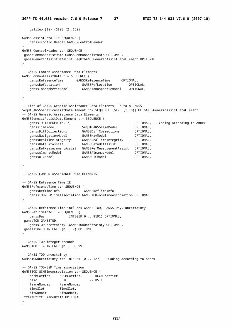
navigationModel (4),timeModelGNSS-UTC (5),timeModelGNSS-GNSS (6),databitassistance (7) } (SIZE (1..16))
-- indicates assistance data that may be needed by the MSAssistanceNeeded ::= SEQUENCE {
gpsAssistanceData GPSAssistanceData OPTIONAL,ganssAssistanceData GANSSAssistanceData OPTIONAL,...
}
6 TOM Protocol Header for RRLP Transport
6.1 GeneralFor the specification of the TOM protocol, see 3GPP TS 44.064.
6.2 Remaining Octets of TOM Protocol Header for RRLPThe number of remaining octet following the first octets of the TOM protocol header for RRLP is one. The encoding of this octet is defined in the figure 6.1 and the table 6.1.
Figure 6.1: Remaining Octets of TOM Protocol Header for RRLP
Table 6.1: C/R bit content
C/R UI frame information field0 Command (SMLC to MS) or Final Response (MS to
SMLC)1 Not Command or Final Response
The setting of the C/R flag is provided by the sending RRLP entity, for further details see 3GPP TS 43.059.
The Spare bits shall be ignored by the receiver and set to 0 by the sender. If a protocol header with more than one remaining octet of the TOM protocol header is received, the additional octets after the first remaining octet shall be ignored by the receiver.
ETSI
ETSI TS 144 031 V7.6.0 (2007-10)373GPP TS 44.031 version 7.6.0 Release 7
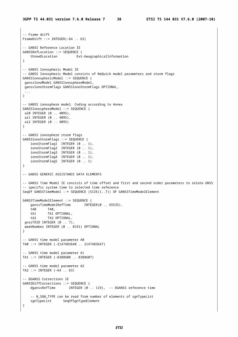
Annex A (informative):Description of Components
A.1 IntroductionThis annex describes the contents of components.
A.2 Measure Position Request
A.2.1 GeneralThe Measure Position Request is a RRLP component from the SMLC to the MS. This component is common to E-OTD,GPS and GANSS (Galileo and Additional Navigation Satellite Systems) location methods. As a response to this component, the MS performs E-OTD,GPS or GANSS measurements and possibly calculates its own position, if the MS and/or the network support these options. It contains the following elements.
Table A.1: Measure Position Request component content
Element Type/Reference PresencePositioning Instructions Positioning Instructions
2.2.1M
E-OTD Reference BTS for Assistance Data
E-OTD Reference BTS for Assistance Data 2.2.2
O
E-OTD Measurement Assistance Data
E-OTD Measurement Assistance Data 2.2.3
O
E-OTD Measurement Assistance Data for System Information List
E-OTD Measurement Assistance Data for System Information List 2.2.4
O
GPS Assistance Data GPS Assistance Data 4.2.4
O
GPS Time Assistance Measurement Request
GPS Time Assistance Measurement Request 2.2.4a
O
GPS Reference Time Uncertainty GPS Reference Time Uncertainty 2.2.4b
O
Velocity Request Velocity Request 2.2.4c OExtended Reference Extended Reference
2.2.5O
GANSS Positioning Method Element
GANSS Positioning Method Element 2.2.1a
O
GANSS Carrier-Phase Measurement Request
GANSS Carrier-Phase Measurement Request 2.2.4d
O
GANSS TOD - GSM Time Association Request
GANSS TOD - GSM Time Association Request 2.2.4e
O
GANSS Assistance Data GANSS Assistance Data 4.2.6
O
Required Response Time Required Response Time 2.2.4f
O
ETSI
ETSI TS 144 031 V7.6.0 (2007-10)383GPP TS 44.031 version 7.6.0 Release 7
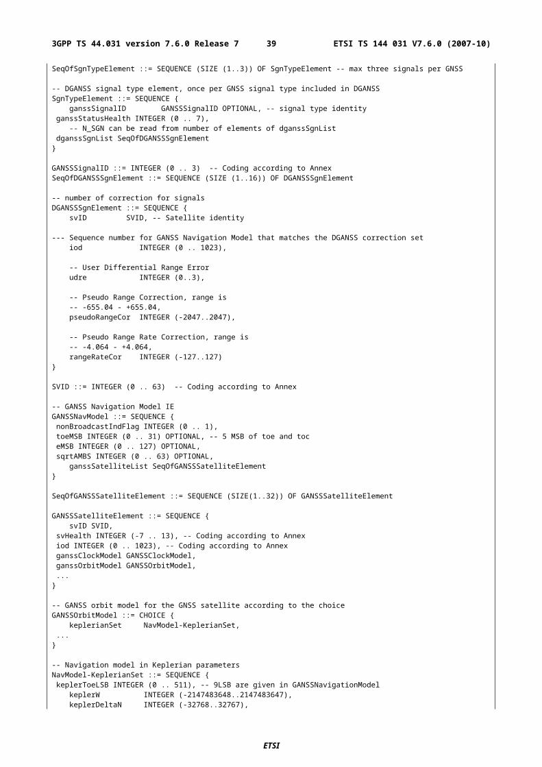
A.2.2 Elements
A.2.2.1 Positioning Instructions Element
The purpose of Positioning Instructions element is to express the allowed/required location method(s), and to provide information required QoS. This element is mandatory in the Measure Position Request message, and contains the following fields:
Method Type
This field indicates whether MS based or assisted version is allowed/requested. If the Methods field includes more than one method, the Method Type applies to all of them. This field is mandatory, and has the following values:
'0': MS assisted;
'1': MS based;
'2': MS based is preferred, but MS assisted is allowed;
'3': MS assisted is preferred, but MS based is allowed.
In GPS positioning methods, "MS based" may indicate either MS Based Assisted GPS method or Conventional GPS method. If "MS based is indicated with no GPS assistance data then the MS may interpret this as either Conventional GPS or MS based A-GPS without assistance data. The same interpretation applies also to the GANSS positioning method.
Positioning Methods
This field indicates which location method or methods should be used. This field is mandatory.
'0': E-OTD;
'1': GPS;
'2': E-OTD or GPS (i.e. both can be reported).
NOTE: If the selected positioning method is "GPS" or "E-OTD or GPS", the field GANSS Positioning Method, if present in a Measure Position Request component, indicates request of GANSS method and indicates the allowed satellite systems.
Response Time
This field indicates the desired response time. However, when performing measurements, the desired response time may be exceeded. This field is mandatory.
The response time is 2N seconds, where N is the value in this field. Thus the desired maximum response time can be 1, 2, 4, 8, 16, 32, 64, or 128 seconds.
Range: 0-7
Accuracy
This field indicates the required accuracy of the location estimate. This is field is mandatory when Method Type is '1', '2', or '3' and optional when Method Type is '0'.
This field is 7 bit Uncertainty Code as defined in 3GPP TS 23.032.
Multiple Sets
This field indicates whether MS is requested to send multiple E-OTD/GPS/GANSS Measurement Information Sets. The maximum number of measurement sets is three. This is field is mandatory. MS is expected to include the current measurement set. Additionally MS may include historical measurement sets, or measure new additional sets if the response time allows that.
In case of the GANSS Positioning Method, this field indicates if the MS is requested to send multiple GANSS Measurement Information sets for measurements performed on different or multiple GANSS frequencies, if the MS
ETSI
ETSI TS 144 031 V7.6.0 (2007-10)393GPP TS 44.031 version 7.6.0 Release 7
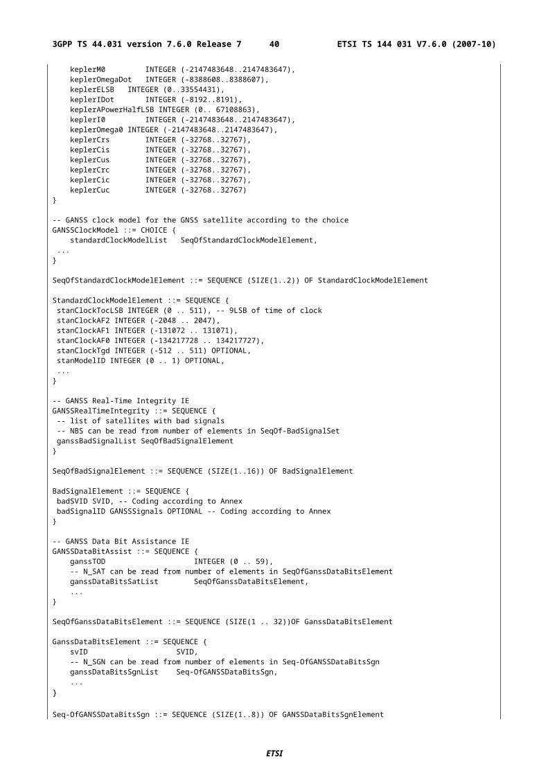
supports this capability. If the MS does not support multiple GANSS frequency measurements, the MS may include historical measurement sets, or measure new additional sets if the response time allows that:
'0': multiple IEs can be send;
'1': sending of multiple sets is not allowed.
Environment Characterization
Environment Characterization field provides the MS with information about expected multipath and NLOS in the current area. This field is optional.
'0': possibly heavy multipath and NLOS conditions (e.g. bad urban or urban).
'1': no or light multipath and usually LOS conditions (e.g. suburban or rural).
'2': not defined or mixed environment.
'3': reserved for future use.
A.2.2.1a GANSS Positioning Method Element
This bit map indicates the satellite systems allowed by the SMLC corresponding to allowance of "GPS" in the Positioning Methods field. Each bit is of type Boolean, where TRUE ("1") means the particular satellite system is allowed. For example EOTD + Galileo method can be indicated by setting "E-OTD or GPS" in PositioningMethod and setting only the "bit 1" to TRUE value in the GANSS Positioning Method element. The MS may not request assistance data or report measurements for the systems that are not indicated in the bit map.
'bit 0': GPS;
'bit 1': Galileo;
'bit 2-15': Reserved for future GNSSes.
A.2.2.2 E-OTD Reference BTS for Assistance Data Element
The RTD and 51 multiframe offset values in the E-OTD Measurement Assistance Data element and the E-OTD Measurement Assistance Data for System Information List element are calculated relative to the BTS indicated in this element. Also the E-OTD Measurement Assistance data for System Information List element, if present, refers to the System Information Neighbor List of this reference BTS.
Inclusion of this parameter is mandatory for E-OTD since it is not possible to reliably default to the current serving BTS for the target MS, as there is a small chance that the SMLC does not know this. If the E-OTD Measurement Assistance data for System Information List element is present, the current serving cell must be the same as reference BTS identified in this element.
BCCH Carrier
This field indicates the absolute RF channel number of BCCH of the reference BTS. This field is mandatory.
Range: 0 - 1023
BSIC
This field indicates the BSIC (Base Station Identity Code) of the reference BTS. This field is mandatory.
Range: 0 - 63
Time Slot Scheme
The Time Slot Scheme field indicates the type of transmission scheme the reference BTS is using. If the MS measures BTSs signals from time slots other than 0 or 4, and it is informed about the burst length schemes used by BTSs, then it can compensate for the possible error. (This is necessary if the MS averages bursts from different time slots, and the BTS uses varying lengths of bursts.) This field is mandatory.
ETSI
ETSI TS 144 031 V7.6.0 (2007-10)403GPP TS 44.031 version 7.6.0 Release 7
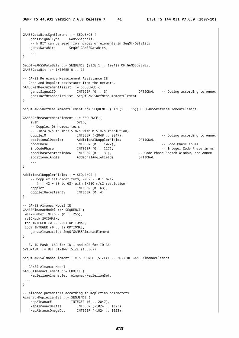
'0' = all time slots are 156.25 bits long.
'1' = time slots 0 and 4 are 157 bits long and other time slots are 156 bits long.
BTS Position
This field contains the BTS position in the format defined in 3GPP TS 23.032. This field is optional, but should be present for MS based E-OTD positioning. The allowed shapes are:
- ellipsoid point;
- ellipsoid point with altitude and uncertainty ellipsoid.
A.2.2.3 E-OTD Measurement Assistance Data Element
This element identifies BTSs that are used for E-OTD measurements. This element helps the MS to make measurements from neighbor BTS (even below decoding level). This element is optional in the Measure Position Request component. The presence of this element means that the MS should try to measure the E-OTD values between the reference BTS and the BTSs identified in this element.
This element is used to deliver E-OTD measurement assistance data for those BTSs, that are not included in the System Information Neighbor List of the reference BTS, if necessary.
The RTD and 51 multiframe offset values are calculated relative to the BTS indicated in the E-OTD Reference BTS for Assistance Data element. This element contains the following fields.
Number of BTSs
This field indicates how many BTSs are included in this IE. This field is mandatory. The maximum number of BTSs in this message for whom the assistance data can be given is 16 (reference BTS and 15 neigbour BTSs). Thus the sum of Number of BTSs field in this IE and total amount of E-OTD Neighbor present bits with value '1' in E-OTD Measurement Assistance Data for System Information List IE can be at a maximum 15.
Range: 1 to 15.
The following fields are repeated for the number of BTSs included in the Number of BTSs field.
BCCH Carrier
This field indicates the absolute RF channel number of BCCH of the particular BTS. This field is mandatory.
Range: 0 - 1023
BSIC
This field indicates the BSIC (Base Station Identity Code) of the particular BTS. This field is mandatory.
Range: 0 - 63
Multiframe Offset
This field indicates the frame difference between the start of the 51 multiframes frames being transmitted from this BTS and the reference BTS. The multiframe offset is defined as TBTS - TRef, where TBTS is the time of the start of the 51 multiframe in the BTS in question, and TRef is the time of the start of the 51 multiframe in the reference BTS. This field is mandatory. Multiframe Offset may be used to calculate the Expected Multiframe Offset (the Multiframe Offset value that MS is expected to measure between this BTS and reference BTS in its current estimated location).
Expected Multiframe Offset = (Multiframe Offset + Adjustment) modulo 51
Adjustment = 1 if Rough RTD - Expected OTD >= 850
Adjustment = -1 if Rough RTD - Expected OTD =< -850
Adjustment = 0 if -400 =< Rough RTD - Expected OTD =< 400
ETSI
ETSI TS 144 031 V7.6.0 (2007-10)413GPP TS 44.031 version 7.6.0 Release 7
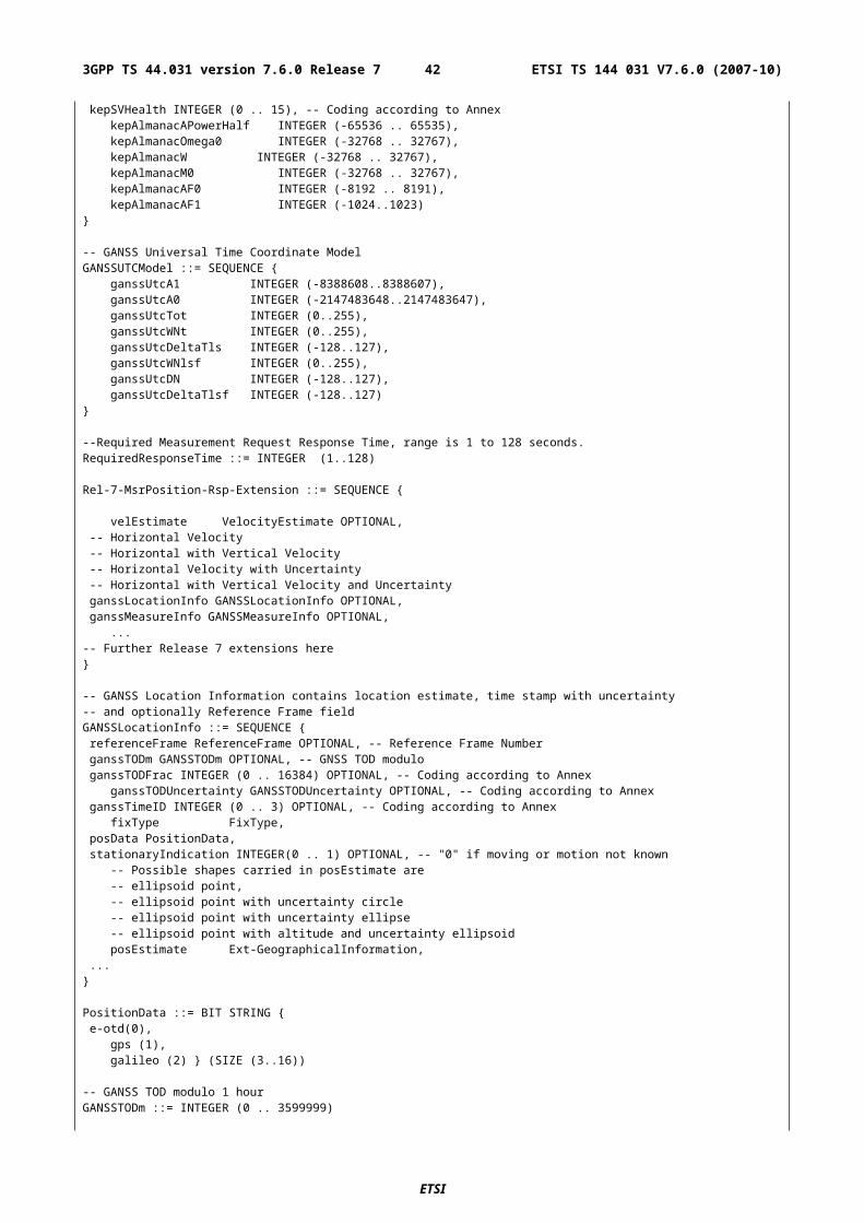
If the Rough RTD - Expected OTD is not within any of the ranges above, an error has occurred and the Expected OTD should be ignored and no Expected Multiframe Offset can be calculated.
Range: 0 - 51
Usable range of Multiframe Offset value is 0 - 50. The Multiframe Offset value 51 shall not be encoded by the transmitting entity and shall be treated by the receiving entity as 0.
Time Slot Scheme
The Time Slot Scheme field indicates the type of transmission scheme the particular BTS is using. If the MS measures BTSs signals from time slots other than 0 or 4, and it is informed about the burst length schemes used by BTSs, then it can compensate for the possible error. (This is necessary if the MS averages bursts from different time slots, and the BTS uses varying lengths of bursts.) This field is mandatory.
'0' = all time slots are 156.25 bits long.
'1' = time slots 0 and 4 are 157 bits long and other time slots are 156 bits long.
Rough RTD
This field indicates the rough RTD value between this BTS and reference BTS. The used resolution is 1 bits. This RTD value is the RTD value of TS0s (i.e. the difference in starting of TS0), not only the RTD between starts of bursts. The RTD is defined as TBTS - TRef, where TBTS is the time of the start of TS0 in the BTS in question, and TRef is the time of the start of the TS0 in the reference BTS. This field is mandatory.
Range: 0 - 1250
Usable range of Rough RTD value is 0 - 1249. The Rough RTD value 1250 shall not be encoded by the transmitting entity and shall be treated by the receiving entity as 0.
Accurate RTD values are needed for MS based E-OTD, i.e. when the MS calculates its own position.
Expected OTD
This field indicates the OTD value that MS is expected to measure between this BTS and reference BTS in its current estimated location. SMLC can estimate MS's location roughly e.g. based on serving BTS coordinates, TA, and possibly some other information. The used resolution is 1 bits. This OTD value is the OTD value of TS0s (i.e. the difference in starting of TS0), not only the OTD between starts of bursts. The OTD is defined as TBTS - TRef, where TBTS is the time of the start of TS0 in the BTS in question, and TRef is the time of the start of the TS0 in the reference BTS. This is element is Release 98 extension and it is an optional element included in Release98-Ext IE. SMLC shall send this element to MS supporting MS Assisted or MS Based E-OTD.
Range: 0 - 1250
Usable range of Expected OTD value is 0 - 1249. The Expected OTD value 1250 shall not be encoded by the transmitting entity and shall be treated by the receiving entity as 0.
Uncertainty Of Expected OTD
This field indicates the uncertainty in Expected OTD value. The uncertainty is related to SMLC"s estimation of MS"s location. The uncertainty defines following search window for MS, that it can use to speed up the OTD measurements:
Expected OTD - Uncertainty < measured OTD < Expected OTD + Uncertainty.
This is element is Release 98 extension and it is an optional element included in Release98-Ext IE. SMLC shall send this element to MS supporting MS Assisted or MS Based E-OTD.
Range is 0 - 7 with following encoding:
'0' 0 < uncertainty <= 2 bit;'1' 2 < uncertainty <= 4 bit;'2' 4 < uncertainty <= 8 bit;'3' 8 < uncertainty <= 12 bit;'4' 12 < uncertainty <= 16 bit;'5' 16 < uncertainty <= 22 bit;
ETSI
ETSI TS 144 031 V7.6.0 (2007-10)423GPP TS 44.031 version 7.6.0 Release 7
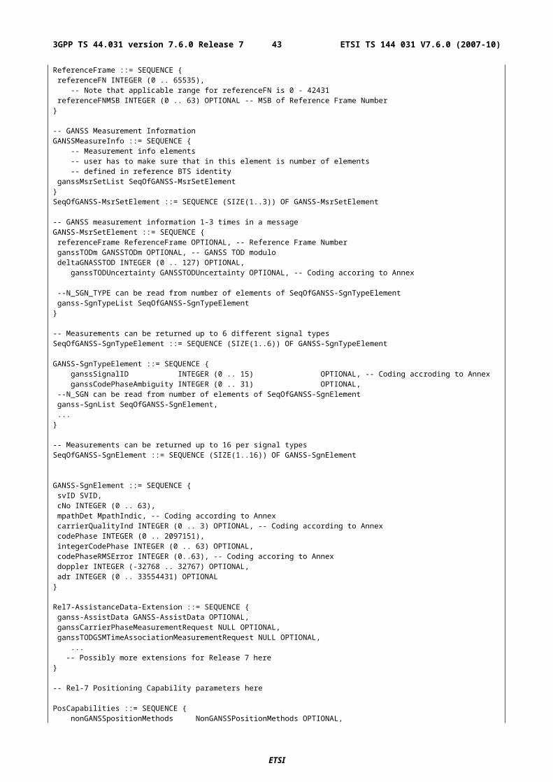
'6' 22 < uncertainty <= 30 bit;'7' uncertainty > 30 bit.
NOTE: If uncertainty in MS's location is x bits, uncertainty in Expected OTD is 2*x (in the worst case). When the uncertainty is given with value "7" no upper bound exist for the uncertainty.
The following fields tell the coordinates of neighbor BTSs that are used for E-OTD measurements, and also fine RTD values. This information allows the MS to calculate its own location. These fields (Fine RTD, Relative north, Relative east and Relative altitude) are optional. All of Fine RTD, Relative north, and Relative east fields must be present, if some of them is included.
Fine RTD
This field indicates the fine RTD value between this BTS and reference BTS. It provides the 1/256 bit duration resolution to the value expressed in the corresponding Rough RTD field. This RTD value is the RTD value of TS0s (i.e. the difference in starting of TS0), not only the RTD between starts of bursts. The RTD is defined as TBTS - TRef, where TBTS is the time of the start of TS0 in the BTS in question, and TRef is the time of the start of the TS0 in the reference BTS. This field is optional.
Range: 0 - 255
Relative North
This field indicates the distance of the neighbor BTS from the reference BTS in north- (negative values mean south) direction. This field is optional. The units are 0.03 seconds. The used reference ellipsoid is WGS 84 ellipsoid.
Range: -200000…200000
Relative East
This field indicates the distance of the neighbor BTS from the reference BTS in east (negative values mean west) direction. This field is optional. The units are 0.03 seconds. The used reference ellipsoid is WGS 84 ellipsoid.
Range: -200000 … 200000
Relative Altitude
This field indicates the altitude of the neighbor BTS relative to the reference BTS in meters. This field is optional.
Range: -4000 .. 4000 meters
A.2.2.4 E-OTD Measurement Assistance Data for System Information List Element
This element identifies those BTSs in the System Information Neighbor List that are used for E-OTD measurements. The System Information Neighbor Lists, to which this assistance data is given, are System Information Neighbor Lists that are sent in the dedicated mode, packet idle mode, packet transfer mode, or dual transfer mode. This element helps the MS to make measurements from those neighbor BTS (even below decoding level). This element is optional in the Measure Position Request component. The presence of this element means that the MS should use the BTSs identified here to the E-OTD measurements.
The RTD and 51 multiframe offset values are calculated relative to the reference BTS. This element contains the following fields.
Number of Neighbors
This field indicates how many neighbors are included in this IE.
Range: 1-32
The following fields are repeated for the number indicated in the Number of Neighbors field.
ETSI
ETSI TS 144 031 V7.6.0 (2007-10)433GPP TS 44.031 version 7.6.0 Release 7
E-OTD Neighbor present
This field indicates whether the information concerning a certain BTS in the Neighbor List is present. Altogether no more than 15 BTS can have the indication "Neighbor is included". The maximum number of BTSs in this message for whom the assistance data can be given is 16 (reference BTS and 15 neigbour BTSs). Thus the sum of total amount of E-OTD Neighbor present bits with value '1' in this IE and Number of BTSs field in E-OTD Measurement Assistance Data IE can be at a maximum 15.
'0' Neighbor not included;
'1' Neighbor is included.
The following fields (BSIC, Multiframe Offset, Time Slot Sscheme and Rough RTD) are included if E-OTD neighbor present field is set to '1'.
BSIC
This field indicates the BSIC (Base Station Identity Code) of the particular BTS. This field is mandatory.
Range: 0 - 63
Multiframe Offset
This field indicates the frame difference between the start of the 51 multiframes frames being transmitted from this BTS and the reference BTS. The multiframe offset is defined as TBTS - TRef, where TBTS is the time of the start of the 51 multiframe in the BTS in question, and TRef is the time of the start of the 51 multiframe in the reference BTS. This field is mandatory. Multiframe Offset may be used to calculate the Expected Multiframe Offset (the Multiframe Offset value that MS is expected to measure between this BTS and reference BTS in its current estimated location).
Expected Multiframe Offset = (Multiframe Offset + Adjustment) modulo 51
Adjustment = 1 if Rough RTD - Expected OTD >= 850
Adjustment = -1 if Rough RTD - Expected OTD =< -850
Adjustment = 0 if -400 =< Rough RTD - Expected OTD =< 400
Range: 0 - 51
Usable range of Multiframe Offset value is 0 - 50. The Multiframe Offset value 51 shall not be encoded by the transmitting entity and shall be treated by the receiving entity as 0.
Time Slot Scheme
The Time Slot Scheme field indicates the type of transmission scheme the particular BTS is using. If the MS measures BTSs signals from time slots other than 0 or 4, and it is informed about the burst length schemes used by BTSs, then it can compensate for the possible error. (This is necessary if the MS averages bursts from different time slots, and the BTS uses varying lengths of bursts.) This field is mandatory.
'0' = all time slots are 156.25 bits long;
'1' = time slots 0 and 4 are 157 bits long and other time slots are 156 bits long.
Rough RTD
This field indicates the RTD value between this BTS and the reference BTS. The used resolution is 1 bit. This RTD value is the RTD value of TS0s (i.e. the difference in starting of TS0), not only the RTD between starts of bursts. The RTD is defined as TBTS - TRef, where TBTS is the time of the start of TS0 in the BTS in question, and TRef is the time of the start of the TS0 in the reference BTS. This field is mandatory.
Range: 0 - 1250
Usable range of Rough RTD value is 0 - 1249. The RoughRTD value 1250 shall not be encoded by the transmitting entity and shall be treated by the receiving entity as 0.
Expected OTD
ETSI
ETSI TS 144 031 V7.6.0 (2007-10)443GPP TS 44.031 version 7.6.0 Release 7
This field indicates the OTD value that MS is expected to measure between this BTS and reference BTS in its current estimated location. SMLC can estimate MS's location roughly e.g. based on serving BTS coordinates, TA, and possibly some other information. The used resolution is 1 bits. This OTD value is the OTD value of TS0s (i.e. the difference in starting of TS0), not only the OTD between starts of bursts. The OTD is defined as TBTS - TRef, where TBTS is the time of the start of TS0 in the BTS in question, and TRef is the time of the start of the TS0 in the reference BTS. This element is Release 98 extension and it is an optional element included in Release98-Ext IE. SMLC shall send this element to MS supporting MS Assisted or MS Based E-OTD.
Range: 0 - 1250
Usable range of Expected OTD value is 0 - 1249. The Expected OTD value 1250 shall not be encoded by the transmitting entity and shall be treated by the receiving entity as 0.
Uncertainty Of Expected OTD
This field indicates the uncertainty in Expected OTD value. The uncertainty is related to SMLC"s estimation of MS"s location. The uncertainty defines following search window for MS, that it can use to speed up the OTD measurements:
Expected OTD - Uncertainty < measured OTD < Expected OTD + Uncertainty.
This element is Release 98 extension and it is an optional element included in Release98-Ext IE. SMLC shall send this element to MS supporting MS Assisted or MS Based E-OTD.
Range is 0 - 7 with following encoding:
'0' 0 < uncertainty <= 2 bit;'1' 2 < uncertainty <= 4 bit;'2' 4 < uncertainty <= 8 bit;'3' 8 < uncertainty <= 12 bit;'4' 12 < uncertainty <= 16 bit;'5' 16 < uncertainty <= 22 bit;'6' 22 < uncertainty <= 30 bit;'7' uncertainty > 30 bit.
NOTE: If uncertainty in MS's location is x bits, uncertainty in Expected OTD is 2*x (in the worst case). When the uncertainty is given with value "7" no upper bound exist for the uncertainty.
The following fields tell the coordinates of neighbor BTSs that are used for E-OTD measurements, and also fine RTD values. This information allows the MS to calculate its own location. These fields (Fine RTD, Relative north, Relative east and Relative altitude) are optional. All of Fine RTD, Relative north, and Relative east fields must be present, if some of them is included.
Fine RTD
This field indicates the fine RTD value between this BTS and reference BTS. It provides the 1/256 bit duration resolution to the value expressed in the corresponding Rough RTD field. This RTD value is the RTD value of TS0s (i.e. the difference in starting of TS0), not only the RTD between starts of bursts. The RTD is defined as TBTS - TRef, where TBTS is the time of the start of TS0 in the BTS in question, and TRef is the time of the start of the TS0 in the reference BTS. This field is optional.
Range: 0 - 255
Relative North
This field indicates the distance of the neighbor BTS from the reference BTS in north- (negative values mean south) direction. This field is optional. The units are 0.03 seconds. The used reference ellipsoid is WGS 84 ellipsoid.
Range: -200000…200000
Relative East
This field indicates the distance of the neighbor BTS from the reference BTS in east (negative values mean west) direction. This field is optional. The units are 0.03 seconds. The used reference ellipsoid is WGS 84 ellipsoid.
Range: -200000 … 200000
ETSI
ETSI TS 144 031 V7.6.0 (2007-10)453GPP TS 44.031 version 7.6.0 Release 7
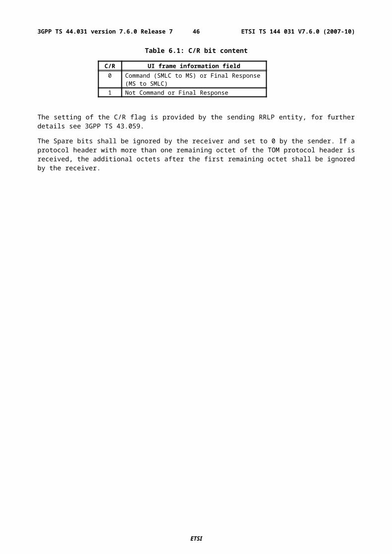
Relative Altitude
This field indicates the altitude of the neighbor BTS relative to the reference BTS in meters. This field is optional.
Range: -4000 .. 4000 meters
A.2.2.4a GPS Time Assistance Measurement Request element
This component does not have any information contents. If this component is present, the MS is requested to return GPS time assistance measurements.
A.2.2.4b GPS Reference Time Uncertainty element
This element provides the accuracy of the relation GPS and GSM time in the Reference Time field in GPS Assistance Data IE. If GPS TOW is the given GPS time, then the true GPS time, corresponding to the provided GSM time as observed at the MS location, lies in the interval (GPS TOW - GPS Reference Time Uncertainty, GPS TOW + GPS Reference Time Uncertainty). An entity that supports this element shall always include it when appropriate. This means that when the element is expected but is not received, lack of support at the sender can be assumed and some implementation dependent default interpretation can then be applied.
The uncertainty r, expressed in microseconds, is mapped to a number K, with the following formula:
r = C*(((1+x)K)-1)
with C = 0.0022 and x = 0.18. With 0 £ K £ 127, a suitably useful range between 0 and 3 second is achieved for the uncertainty, while still being able to code down to values as small as 0.3 nanoseconds. To encode any higher value of uncertainty than that corresponding in the above formula to K=127, the same value, K=127, shall also be used. The uncertainty is then coded on 7 bits, as the binary encoding of K.
Table A.1a: Example values for the GPS Reference Time Uncertainty Parameter Format
Value of K Value of uncertainty0 0 nanoseconds1 0.396 nanoseconds2 0.863 nanoseconds- -50 8.64 microseconds- -127 ≥ 2.96 seconds
A.2.2.4c Velocity Request element
If this element is present, the MS is requested to return a velocity estimate along with the location estimate. Requesting velocity does not guarantee its delivery, if conditions support its availability and it is requested it will be provided.
A.2.2.4d GANSS Carrier-Phase Measurement Request Element
This component does not have any information contents. If this component is present, the MS is requested to return carrier phase measurements in the GANSS Measurement Information IE.
A.2.2.4e GANSS TOD - GSM Time Association Request Element
This component does not have any information contents. If this component is present, the MS is requested to return GANSS TOD - GSM time association measurements. Only either GPS Timing Assistance Measurement Request Element or GANSS TOD - GSM Time Association Measurement Request should be present in Measure Position Request.
ETSI
ETSI TS 144 031 V7.6.0 (2007-10)463GPP TS 44.031 version 7.6.0 Release 7
A.2.2.4f Required Response Time
This element indicates the maximum response time that shall be allowed for the positioning request in the MS. When this element is received, the MS shall send an RRLP Measure Position Response before the required response time has elapsed.
When this element is received, the MS shall ignore the Response Time field in the Positioning Instructions element.
The Required Response Time has a value from 1 to 128 seconds.
A.2.2.5 Extended Reference IE
This element is mandatory in any RRLP Measure Position Request component, any RRLP Assistance Data component, any RRLP Positioning Capability Request component and any RRLP Positioning Capability response component.
NOTE: For reasons of backward compatibility, the IE is not defined for a Release 4 or earlier SMLC and would be ignored, when received, by a Release 4 or earlier MS. Additionally, other requirements associated with this IE would not be supported by a Release 4 or earlier MS or SMLC.
The Extended Reference IE contains the following elements:
SMLC code: an integer in the range 0-63 distinguishing any SMLC from other neighbour SMLCs in the same Routing Area. Each SMLC is assigned a specific SMLC ID value. The values assigned to neighbour SMLCs in the same Routing Area between which inter-NSE cell change is possible should be different.
Transaction ID: an integer in the range 0-262143 distinguishing different RRLP transactions in different MSs currently being served by the same SMLC. An SMLC shall assign a different transaction ID to each currently open RRLP transaction for positioning and assistance data delivery among all target MSs. When any RRLP transaction for any MS is completed in the SMLC (e.g. the MS has sent a correctly formatted RRLP Measure Position Response or Assistance Data Ack.) or if the transaction is aborted (e.g. SMLC timeout on an RRLP response), the associated transaction ID value shall become free and may be later assigned to a new RRLP transaction by the SMLC. When any transaction ID value becomes free, an SMLC should attempt to wait for at least 128 seconds (the maximum defined RRLP response time from an MS) before reassigning the same value.
ETSI
ETSI TS 144 031 V7.6.0 (2007-10)473GPP TS 44.031 version 7.6.0 Release 7
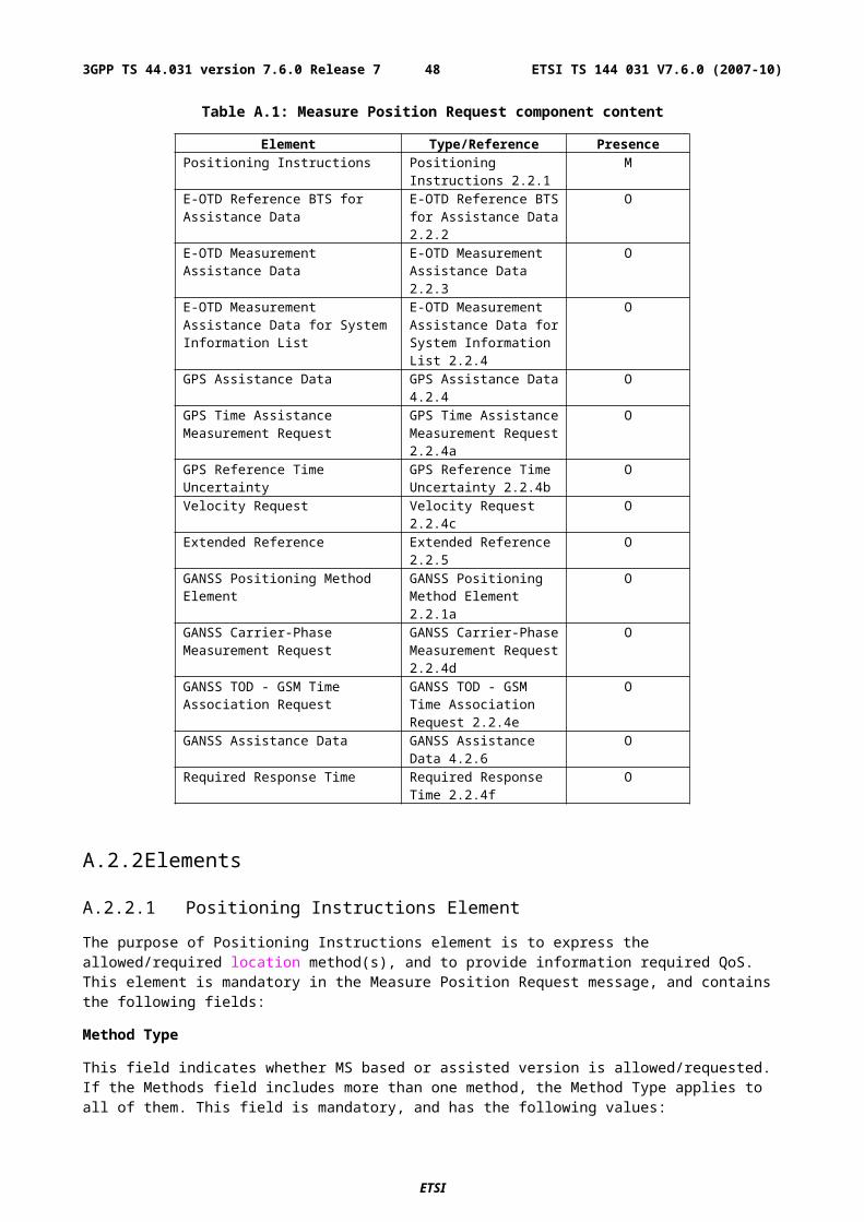
A.3 Measure Position Response
A.3.1 GeneralThe Measure Position Response is a RRLP component from the MS to the network. It is the response to the Measure Position Request. It contains the following elements. One of the five elements containing measurement data or location estimate (E-OTD Measurement Information, Location Information, GPS Measurement Information, GANSS Measurement Information or GANSS Location Information) or Location Information Error element must be included.
Table A.2: Measure Position Response component content
Element Type/Reference PresenceMultiple Sets Multiple Sets 3.2.1 OReference BTS Identity Reference BTS Identity
3.2.2O
E-OTD Measurement Information E-OTD Measurement Information 3.2.3
O
Location Information Location Information 3.2.4
O
GPS Measurement Information GPS Measurement Information 3.2.5
O
Location Information Error Location Information Error 3.2.6
C
GPS Time Assistance Measurements
GPS Time Assistance Measurements 3.2.6a
O
Velocity Estimate Velocity Estimate 3.2.6b OExtended Reference Extended Reference
3.2.7C
Uplink RRLP Pseudo Segmentation Indication
Uplink RRLP Pseudo Segmentation Indication 3.2.8
C
GANSS Location Information GANSS Location Information 3.2.9
O
GANSS Measurement Information GANSS Measurement Information 3.2.10
O
A.3.2 Elements
A.3.2.1 Multiple Sets Element
This element indicates how many E-OTD Measurement Information sets, GPS Measurement Information sets or GANSS Measurement Information sets, and Reference BTS Identities are included to this element. This element is optional. If this element is absent, a single measurement set is included.
Number of E-OTD/GPS/GANSS Measurement Information Sets
This field indicates the number of Number of E-OTD/GPS/GANSS Measurement Information sets included to this component. This field is mandatory. If two or more types of measurement elements are present, then there are the equal number of them, and each pair has the same reference BTS.
Range: 2 - 3
Number of Reference BTS
This field indicates the number of reference BTSs used in this component. This field is mandatory.
Range: 1-3
Reference BTS relation to Measurement Elements
ETSI
ETSI TS 144 031 V7.6.0 (2007-10)483GPP TS 44.031 version 7.6.0 Release 7
This field indicates how the reference BTSs listed in this element relate to measurement sets later in this component. This field is conditional and included only if Number of E-OTD/GPS/GANSS Measurement Information Sets is '3' and Number of Reference BTSs is '2'.
'0' = First reference BTS is related to first and second E-OTD/GPS/GANSS Measurement Information Sets, and second reference BTS is related to third E-OTD/GPS Measurement Information Sets.
'1' = First reference BTS is related to first and third E-OTD/GPS/GANSS Measurement Information Sets, and second reference BTS is related to second E-OTD/GPS/GANSS Measurement Information Sets.
'2' = First reference BTS is related to first E-OTD/GPS/GANSS Measurement Information Sets, and second reference BTS is related to second and third E-OTD/GPS/GANSS Measurement Information Sets.
If this field is not included, the relation between reference BTS and Number of E-OTD/GPS/GANSS Measurement Information Sets is as follows:
- if there are three sets and three reference BTSs -> First reference BTS relates to first set, second reference BTS relates to second set, and third reference BTS relates to third set;
- if there are two sets and two reference BTS -> First reference BTS relates to first set, and second reference BTS relates to second set;
- if there is only one reference BTS and 1-3 sets -> this reference BTS relates to all sets.
A.3.2.2 Reference BTS Identity Element
This element identifies the reference BTS(s). This element is conditional to the number of reference BTSs. It is mandatory, if there is more than one reference BTS, and optional otherwise. If this element is not included, the Reference BTS, used in other elements, is the current serving BTS of MS. If this element is included, the BTSs defined here are used as Reference BTSs in all other elements.
The following fields are repeated for the number of reference BTSs included in the Number of Reference BTS field.
CellIdType
This field indicates is the identity method of the Reference BTS. This field is mandatory within this element.
'0' = Cell identity is told using BSIC and BCCH carrier.
'1' = Cell identity is told using CI, and the LAC is the same as the current serving BTS.
'2' = Cell identity is told using an index referring to the BTS listed in the Measure Position Request component (the indicated reference BTS is 1)
'3' = Cell identity is told using an index referring to the BTS listed in the BCCH allocation list (System Information Neighbor Lists) of the serving BTS. This type of reference identity shall not be used by the MS unless it has received the "E-OTD Measurement Assistance Data for System Information List Element" from the SMLC for this cell.
'4' = Cell identity is told using CI, and the LAC.
Reference LAC
This field indicates the Location Area Code of the reference BTS. The purpose of the Location Area Code is to identify a location area. This field is conditional, and included, if CellIDType field is '4'.
Range: 0 - 65535
Reference CI
This field indicates the Cell Identity value of the reference BTS. The purpose of the Cell Identity value is to identify a cell within a location area. This field is conditional, and included, if CellIDType field is '1' or '4'.
Range: 0 - 65535
Reference BCCH Carrier
ETSI
ETSI TS 144 031 V7.6.0 (2007-10)493GPP TS 44.031 version 7.6.0 Release 7
This field indicates the absolute RF channel number of the BCCH of the reference base station. BCCH carrier field is conditional and is included only if CellIdType is set '0'.
Range: 0 - 1023
Reference BSIC
This field indicates the BSIC (Base Station Identity Code of the base station).
BSIC field is conditional and is included only if CellIdType is set '0' or '3'.
Range: 0 - 63
Request Index
This field indicates an index identifying the reference BTS by referring to the BTSs listed in the Measure Position Request component (the indicated reference BTS in the Measure Position Request component has the index value 1, and possible next BTS '2', and so on )
This field is conditional and included only if CellIdType is set to '2'.
Range: 1-16
System Info Index
This field indicates an index identifying the reference BTS by referring to the BCCH allocation list (System Information Neighbor List) of the serving BTS .
This field is conditional and included only if CellIdType is set to '3'.
Range: 1-32
A.3.2.3 E-OTD Measurement Information Element
The purpose of the E-OTD Measurement Information element is to provide OTD measurements of signals sent from the reference and neighbor based stations. The length of this element depends on the number of neighbor cells for which OTD measurements have been collected. This element is optional in the Measure Position Response component. It is included in the Measure Position Response component, if the network has requested the mobile to perform the MS assisted E-OTD method. BTSs which cannot be measured or whose measurements are excessively inaccurate need not be reported. The MS may include measurements for other BTSs not given in the assistance data by the SMLC.
The E-OTD and 51 multiframe offset values are reported relative to the reference BTS as defined in the previous sub-clauses.
The following fields are repeated for each measurement set.
Reference Frame Number
This field indicates the frame number of the last measured burst from the reference BTS modulo 42432. This information can be used as a time stamp for the measurements. This field is mandatory.
Range: 0 - 42431
Reference Time Slot
Reference Time Slot indicates the time slot modulo 4 relative to which the MS reports the reference BTS measurements. This field is mandatory.
Range: 0 to 3
NOTE 1: If MS does not know timeslot scheme, the MS reports the used timeslot. MS can only report results based on one time slot (N) or two time slots (N and N+4). If the MS knows the timeslot scheme, it can make measurements from several timeslots and reports that the used timeslot is zero (and makes correction).
Reference Quality
ETSI
ETSI TS 144 031 V7.6.0 (2007-10)503GPP TS 44.031 version 7.6.0 Release 7
Reference Quality field includes the standard deviation of the TOA measurements from the reference BTS with respect to TRef (where TRef is the time of arrival of signal from the reference BTS used to calculate the OTD values). This field is optional. The Reference Quality field can be used to evaluate the reliability of E-OTD measurements in the SMLC and in weighting of the E-OTD values in the location calculation.
Following linear 5 bit encoding is used:
'00000' 0 - (R*1-1) meters;'00001' R*1 - (R*2-1) meters;'00010' R*2 - (R*3-1) meters;…'11111' R*31 meters or more.
where R is the resolution defined by Std Resolution field. For example, if R=20 meters, corresponding values are 0 - 19 meters, 20 - 39 meters, 40 - 59 meters, …, 620+ meters.
Number of Measurements
Number of Measurements for the Reference Quality field is used together with Reference Quality to define quality of the reference base site TOA. The field indicates how many measurements have been used in the MS to define the standard deviation of the measurements. Following 3 bit encoding is used:
'000': 2-4;'001': 5-9;'010': 10-14;'011': 15-24;'100': 25-34;'101': 35-44;'110': 45-54;'111': 55 or more.
This field is optional.
Std Resolution
Std Resolution field includes the resolution used in Reference Quality field and Std of EOTD Measurements field. Encoding on 2 bits as follows:
'00' 10 meters;'01' 20 meters;'10' 30 meters;'11' Reserved.
This field is mandatory.
TA Correction
This field indicates the estimate of the time difference between the moment that the MS uses to adjust its internal timing for reception and transmission (e.g. corresponding to maximum energy) and the estimate of the reception of the first arriving component from the serving BTS. This value can be used as a correction by the SMLC to the Timing Advance (TA) value when the distance between the MS and the serving BTS is estimated based on TA.
The value TACor in this field corresponds to the TA Correction in bit periods as follows:
- TA Correction in bit periods = TACor/64 -8.
TA Correction has the resolution of 1/64 bit period, and the range - 8 … +7 bit periods. Negative TA Correction in bits indicates that the first signal component from the serving BTS is estimated to arrive before the moment used for communication. This field is optional.
Range: 0-960
Number of Measured Neighbors
This field indicates the number of different neighbor BTSs. This field is mandatory.
ETSI
ETSI TS 144 031 V7.6.0 (2007-10)513GPP TS 44.031 version 7.6.0 Release 7
Range: 0 - 10
NOTE 2: If the MS can not measure any neighbor BTSs, then this value is set to '0'.
The following fields are repeated for the number of BTSs included in the Number of Measured Neighbors field.
Neighbor Identity Present
The presence of this field is conditional, it shall not be present in the first set. It is mandatory for the other sets. This field indicates whether the identity information (i.e. CellIDType and possibly Neighbor CI / Neighbor BCCH Carrier / Neighbor BSIC / Neighbor Multiframe Offset / Request Index / System Info Index fields) concerning a certain BTS is present or whether the BTS identity is given as reference to the first measurement set.
'0' Identity information not included, and identity of this BTS is same as the identity of BTS in first set with same sequence number.
'1' Identity information is included.
CellIdType
This field indicates is the identity method of the cell. This field is conditional, and included if Neighbor Identity Present is '1'. If CellIdType field is not present, the following fields can not be present either: Neighbor CI, Neighbor BCCH Carrier, Neighbor BSIC, Neighbor Multiframe Offset, Request Index, System Info Index.
'0' = Cell identity is told using BSIC and BCCH carrier.
'1' = Cell identity is told using CI, and the LAC is the same as the current serving BTS.
'2' = Cell identity is told using 51 Multiframe offset and BCCH carrier.
'3' = Cell identity is told using an index referring to the BTS listed in the Measure Position Request component (the indicated reference BTS is 1).
'4' = Cell identity is told using an index referring to the BTS listed in the BCCH allocation list (System Information Neighbor Lists) of the serving BTS. This type of neighbor identity shall not be used by the MS unless it has received the "E-OTD Measurement Assistance Data for System Information List Element" from the SMLC for this cell.
'5' = Cell identity is told using CI and the LAC.
NOTE: The MS can decide which of these methods to use. The CellIdType '3' and '4' are preferred.
Neighbor LAC
This field indicates the Location Area Code of the neighbor BTS. The purpose of the Location Area Code is to identify a location area. This field is conditional, and included, if CellIDType field is '5'.
Range: 0 - 65535
Neighbor CI
This field indicates the Cell Identity of the particular neighbor cell. The purpose of the Cell Identity value is to identify a cell within a location area.
Neighbor CI field is conditional and is included only if CellIdType is set '1' or '5' and the CI value of the given cell is available.
Range: 0 - 65535
Neighbor BCCH Carrier
This field indicates the absolute RF channel number of the BCCH of the neighbor base station. BCCH carrier field is conditional and is included only if CellIdType is set '0' or '2'.
Range: 0 - 1023
Neighbor BSIC
ETSI
ETSI TS 144 031 V7.6.0 (2007-10)523GPP TS 44.031 version 7.6.0 Release 7
This field indicates the BSIC (Base Station Identity Code of the base station).
BSIC field is conditional and is included only if CellIdType is set '0' or '4'.
Range: 0 - 63
Neighbor Multiframe Offset
This field indicates the frame difference between the start of the 51 multiframes frames arriving from this BTS and the reference BTS. The multiframe offset is defined as TBTS - TRef, where TBTS is the time of the start of the 51 multiframe in the BTS in question, and TRef is the time of the start of the 51 multiframe in the reference BTS. This field is conditional and included only if CellIdType is set to '2'.
Range: 0 - 51
Request Index
This field indicates an index identifying the reference BTS by referring to the BTSs listed in the Measure Position Request component (the indicated reference BTS in the Measure Position Request component has the index value 1, and possible next BTS '2', and so on).
This field is conditional and included only if CellIdType is set to '3'.
Range: 1-16
System Info Index
This field indicates an index identifying the reference BTS by referring to the BCCH allocation list (System Information Neighbor List) of the serving BTS.
This field is conditional and included only if CellIdType is set to '4'.
Range: 1-32
Neighbor Time Slot
Neighbor Time Slot indicates the time slot modulo 4 relative to which the MS reports the neighbor BTS measurements. This field is mandatory.
Range: 0 to 3
NOTE 3: If the MS does not know the timeslot scheme, the MS reports the used timeslot. MS can only report a result based on one time slot (N) or two time slots (N and N+4). If the MS knows the timeslot scheme, the MS can make measurements from several timeslots and reports that the used timeslot is zero (and makes correction).
Number of EOTD Measurements
Number of Measurements field is used together with Std of EOTD Measurements field to define quality of a reported EOTD measurement. The field indicates how many EOTD measurements have been used in the MS to define the standard deviation of these measurements. Following 3 bit encoding is used.
'000': 2-4;'001': 5-9;'010': 10-14;'011': 15-24;'100': 25-34;'101': 35-44;'110': 45-54;'111': 55 or more.
This field is mandatory.
Std of EOTD Measurements
ETSI
ETSI TS 144 031 V7.6.0 (2007-10)533GPP TS 44.031 version 7.6.0 Release 7
Std of EOTD Measurements field includes standard deviation of EOTD measurements. This field is mandatory. It can be used to evaluate the reliability of EOTD measurements in the SMLC and in weighting of the OTD values in location calculation.
Following linear 5 bit encoding is used:
'00000' 0 - (R*1-1) meters;'00001' R*1 - (R*2-1) meters;'00010' R*2 - (R*3-1) meters;…'11111' R*31 meters or more.
where R is the resolution defined by Std Resolution field. For example, if R=20 meters, corresponding values are 0 - 19 meters, 20 - 39 meters, 40 - 59 meters, …, 620+ meters.
OTD
This field indicates the measured OTD value between the receptions of signals from the reference and the neighbor BTS. The OTD is defined as TNbor - TRef (modulo burst length) where TNbor is the time of arrival of signal from the neighbor BTS, and TRef is the time of arrival of signal from the reference BTS. The reporting resolution of the OTD value is 1/256 bit. This field is mandatory.
Range: 0 - 39999
A.3.2.3a E-OTD Measurement Extended Information Element
The purpose of the E-OTD Measurement Ext Information element is to provide OTD measurements of signals sent from the reference and neighbour base stations. The length of this element depends on the number of neighbour cells for which OTD measurements have been collected. This element is optional in the Measure Position Response component. It is included in the Measure Position Response component, if E-OTD measurements didn"t fit in the E-OTD Measurement Information Element.
The E-OTD and 51 multiframe offset values are reported relative to the reference BTS as defined in the previous sub-clauses.
The following fields are valid only for the first set of measurements
Number of Measured Neighbors
This field indicates the number of different neighbor BTSs. This field is mandatory.
Range: 0 - 5
NOTE: If the MS can not measure any neighbor BTSs, then this value is set to '0'.
ETSI
ETSI TS 144 031 V7.6.0 (2007-10)543GPP TS 44.031 version 7.6.0 Release 7
The following fields are repeated for the number of BTSs included in the Number of Measured Neighbors field. They are defined in the previous sub-clause :
- CellIdType,
- Neighbor LAC,
- Neighbor CI,
- Neighbor BCCH Carrier,
- Neighbor BSIC,
- Neighbor Multiframe Offset,
- Request Index,
- System Info Index,
- Neighbor Time Slot,
- Number of EOTD Measurements,
- Std of EOTD Measurements,
- OTD
A.3.2.4 Location Information Element
The purpose of Location Information element is to provide the location estimate from the MS to the network, if the MS is capable of determining its own position. Optionally, the element may contain the velocity parameters computed by the MS.
This element is optional. This element contains the following fields.
Reference Frame
This field specifies the reference BTS Reference Frame number during which the location estimate was measured. The time of the Reference Frame boundary is as observed by the MS, ie without Timing Advance compensation. This field is mandatory. However, if the Reference Frame number is within (42432..65535), the value of this field shall be ignored and in that case the MS should provide GPS TOW if available.
Table A.3: Reference Frame field contents
Parameter # of Bits Resolution Range UnitsReference Frame 16 --- 0 - 65535 frames
Note that expected values for Reference Frame are in range 0 - 42431.
GPS TOW
This field specifies the GPS TOW for which the location estimate is valid , rounded down to the nearest millisecond unit. This field is optional but shall be included if GPS Time Assistance Measurements are included. If GPS Time Assistance Measurements are included in the RRLP Measure Position Response, the MS shall align GPS System time (as defined by the GPS TOW and the GPS TOW Subms fields) with the reported GSM frame boundary observed by the MS at that time.
Table A.4: GPS TOW field contents
Parameter # of Bits Resolution Range UnitsGPS TOW 24 1 ms 0 - 14399999 ms
The 24 bits of GPS TOW are the least significant bits. The most significant bits shall be derived by the Serving Mobile Location Center to unambiguously derive the GPS TOW.
ETSI
ETSI TS 144 031 V7.6.0 (2007-10)553GPP TS 44.031 version 7.6.0 Release 7
Fix Type
This field contains an indication as to the type of measurements performed by the MS: 2D or 3D. This field is mandatory.
'0' = 2D fix.
'1' = 3D fix.
Position Estimate
This field contains the calculated position estimate in the format defined in 3GPP TS 23.032. The allowed shapes are:
- ellipsoid Point;
- ellipsoid point with uncertainty circle;
- ellipsoid point with uncertainty ellipse;
- ellipsoid point with altitude and uncertainty ellipsoid.
A.3.2.5 GPS Measurement Information Element
The purpose of the GPS Measurement Information element is to provide GPS measurement information from the MS to the SMLC. This information includes the measurements of code phase and Doppler, which enables the network-based GPS method where position is computed in the SMLC. The proposed contents are shown in table A.5, and the individual fields are described subsequently. See also Figure A.1 for an illustration of the relation between some of the fields.
ETSI
ETSI TS 144 031 V7.6.0 (2007-10)563GPP TS 44.031 version 7.6.0 Release 7
Figure A.1. Exemplary definitions of GPS measurement information fields.
ETSI
ETSI TS 144 031 V7.6.0 (2007-10)573GPP TS 44.031 version 7.6.0 Release 7
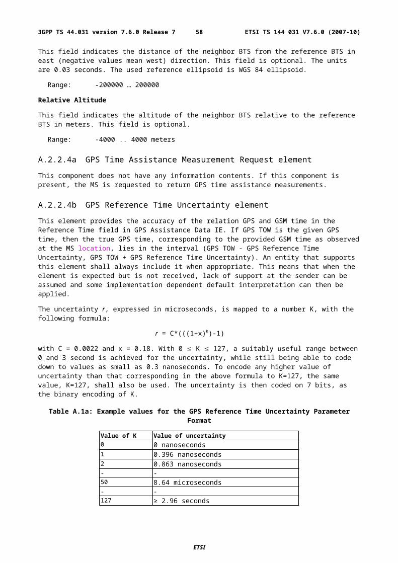
This element is included in the Measure Position Response component if the network has requested the mobile to perform mobile-assisted location measurements using a GPS location method.
Following fields are repeated a number of times told in Number of E-OTD/GPS Measurement Sets field if Multiple Sets element is included. If Multiple Sets element is not included, the default value for sets is one (i.e. the following fields are present only once).
Table A.5: GPS Measurement Information element content
Element fields Presence OccurrencesReference Frame O 1GPS TOW M 1# of Satellites (N_SAT) M 1Measurement Parameters M N_SAT
The following paragraphs describe the content of each information field of this element.
Reference Frame
This field is optional.
Table A.6: Reference Frame field contents
Parameter # of Bits Resolution Range UnitsReference Frame 16 --- 0 - 65535 frames
Note that expected values for Reference Frame are in range 0 - 42431. If Reference Frame and GPS Time Assistance Measurements both are included in the RRLP Measure Position Response, the code phase measurements shall be aligned with the reported GSM frame boundary observed by the MS at that time, as indicated in Figure A.1. The time of the Reference Frame boundary is as observed by the MS, ie without Timing Advance compensation.
GPS TOW
This field specifies the GPS TOW for which the location estimate is valid, rounded down to the nearest millisecond unit.This field is mandatory.
Table A.7: GPS TOW field contents
Parameter # of Bits Resolution Range UnitsGPS TOW 24 1 ms 0 - 14399999 ms
The 24 bits of GPS TOW are the least significant bits. The most significant bits shall be derived by the Serving Mobile Location Center to unambiguously derive the GPS TOW.
NOTE: The GPS Reference Time Uncertainty, if present, indicates the accuracy of GPSTOW, as described in sub-clause A.3.2.6.a.
# of Satellites (N_SAT)
Number of Measurements
This field specifies the number of measurements for which measurements satellites are provided in the component. This value represents the number of satellites that were measured by the MS. This value of N_SAT determines the length of the payload portion of the component. Typical range for N_SAT is four to a maximum of 12. This field is mandatory and occurs once per set.
Table A.7a: # of Satellites field contents
Parameter # of Bits Resolution Range UnitsN_SAT 4 --- 1 - 16 ---
ETSI
ETSI TS 144 031 V7.6.0 (2007-10)583GPP TS 44.031 version 7.6.0 Release 7
Measurement Parameters
This field contains information about the measurements of code phase and Doppler, which enables the network-based method where position is computed in the SMLC. This field is mandatory and occurs N_SAT times per message.
Table A.8: Measurement Parameters field contents
Parameter # of Bits Resolution Range UnitsSatellite ID 6 --- 0 - 63 ---C/No 6 1 0 - 63 dB-HzDoppler 16 0.2 6553.6 HzWhole Chips 10 1 0 - 1022 chipsFractional Chips 11 2-10 0 - (1-2-10) chipsMultipath Indicator 2 see Table A.9 TBD ---Pseudorange RMS Error
6 3 bit mantissa3 bit exp
0.5 - 112 m
Satellite ID
This field identifies the particular satellite for which the measurement data is valid. This values 0 - 63 represent satellite PRNs 1 - 64, respectively.
C/N0
This field contains the estimate of the carrier-to-noise ratio of the received signal from the particular satellite used in the measurement. It is given in whole dBs and has a range of 0 to 63. Typical levels observed by MS-based GPS units will be in the range of 20 dB to 50 dB.
Doppler
This field contains the Doppler measured by the MS for the particular satellite signal. This information can be used to compute the 3-D velocity of the MS. The Doppler range is sufficient to cover the potential range of values measured by the MS.
Whole Chips
This field contains the whole value of the code-phase measurement made by the MS for the particular satellite signal at the time of measurement, in units of 1 GPS chip in the range from 0 to 1022 chips, where increasing binary values of the field signify increasing measured pseudoranges. The code phase measurement is divided into two fields, "Whole Chips" and "Fractional Chips".
Fractional Chips
This field contains the fractional value of the code-phase measurement made by the MS for the particular satellite signal at the time of measurement. The resolution of the fractional portion is approximately 0,3 m.
NOTE: The actual ASN.1 coding of this field reserves 11 bits for legacy compatibility. Only the 10 least significant bits are actually required to code the values (0..1023)
Multipath Indicator
This field contains the Multipath Indicator value. This parameter is specified according to the representation described in table A.9.
Table A.9: Multipath Indicator values and associated indications
Value Multipath Indication00 Not measured01 Low, MP error < 5m10 Medium, 5m < MP error < 43m11 High, MP error > 43m
Range: 0 - 3
Pseudorange RMS Error
ETSI
ETSI TS 144 031 V7.6.0 (2007-10)593GPP TS 44.031 version 7.6.0 Release 7
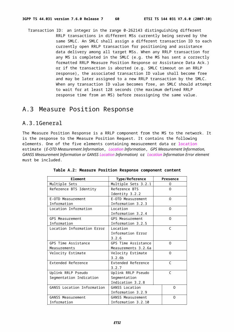
This field contains a Pseudorange RMS Error value.
Range: 0,5 m to 112 m
NOTE: This parameter is specified according to a floating-point representation as described in Table A.10.
Table A.10: Pseudorange RMS Error representation
Index Mantissa Exponent Floating-Point value, xi Pseudorange value, P
0 000 000 0.5 P < 0.51 001 000 0.5625 0.5 <= P < 0.5625I x y 0.5 * (1 + x/8) * 2y xi-1 <= P < xi
62 110 111 112 104 <= P < 11263 111 111 -- 112 <= P
A.3.2.6 Location Information Error Element
The purpose of Location Information Error element is to provide the indication of error and the reason for it, when the MS can not perform the required location or the network can not determine the position estimate. The element may also indicate what further assistance data may be needed by the target MS to produce a successful location estimate or location measurements. This element is optional. This element has the following fields.
Error Reason
This field indicates the reason for error. This field is mandatory.
'0': Undefined error.'1': There were not enough BTSs to be received when performing mobile based E-OTD.'2': There were not enough GPS satellites to be received, when performing GPS location.'3': E-OTD location calculation assistance data missing.'4': E-OTD assistance data missing.'5': GPS location calculation assistance data missing.'6': GPS assistance data missing.'7': Requested method not supported.'8': Location request not processed.'9': Reference BTS for GPS is not the serving BTS.'10': Reference BTS for E-OTD is not the serving BTS.'11': There were not enough GANSS satellites received, when performing GANSS location.'12': GANSS assistance data missing.'13': Reference BTS for GANSS is not the serving BTS.
Additional Assistance Data
This field is optional. Its presence indicates that the target MS will retain assistance data already sent by the SMLC. The SMLC may send further assistance data for any new location attempt but need not resend previous assistance data. The field may contain the following:
GPS Assistance Data: Necessary additional GPS assistance data (structure and encoding as for the GPS Assistance Data IE in 3GPP TS 49.031 excluding the IEI and length octets)
GANSS Assistance Data: Necessary additional GANSS assistance data (structure and encoding as for the GANSS Assistance Data IE in 3GPP TS 49.031 excluding the IEI and length octets)
A.3.2.6a GPS Time Assistance Measurements Element
This IE contains measurements that are used to define an accurate relation between GSM and GPS time or to provide additional GPS TOW information for MS Assisted A-GPS. The contents are shown in Table A.10a, and the individual fields are described subsequently.
ETSI
ETSI TS 144 031 V7.6.0 (2007-10)603GPP TS 44.031 version 7.6.0 Release 7
Table A.10a: GPS Time Assistance Measurements Information element content
Element fields PresenceReference Frame MSB OGPS TOW Subms ODelta TOW OGPS Reference Time Uncertainty O
Reference Frame MSB
This field shall be included when GPS-GSM time association is provided for either MS Based A-GPS or MS Assisted A-GPS. It indicates the Most Significant Bits (MSBs) of the frame number of the reference BTS corresponding to the GPS measurement or location estimate. Starting from the complete GSM frame number denoted FN, the MS calculates Reference Frame MSB as
Reference Frame MSB = floor(FN/42432)
The complete GSM frame number FN can then be reconstructed in the SMLC by combining the fields Reference Frame with Reference Frame MSB in the following way
FN = Reference Frame MSB*42432+Reference Frame
Range: 0-63
GPS TOW Subms
This field is only applicable for MS-Based A-GPS. This field indicates in units of 100ns the submillisecond part of the GPS time of measurement. This field together with the GPS TOW field in the Location Information Element provides a more accurate time stamp of the location estimate for MS based AGPS Expressed in units of microseconds. The precise GPS time of measurements in milliseconds is thus equal to
GPS TOW + 0.0001*GPS TOW Subms
The estimation of precise GPS time of measurement using AGPS is vulnerable to millisecond ambiguities. Therefore the MS shall only report this field when it is confident that any millisecond ambiguities have been avoided.
Range: 0-9999
Delta TOW
This field is only applicable for MS-Assisted A-GPS. This field specifies the difference in milliseconds between the GPS TOW reported in the GPS Measurement Information Element and the millisecond part of the SV time tsv_1 of the first SV in the list reported from the MS. Figure A.1 shows an example of Delta TOW calculation. The Delta TOW is defined as Delta TOW = GPS TOW - fix(tsv_1)
where fix() denotes rounding to the nearest integer towards zero. The estimation of tsv_1 which forms the basis for the calculation of Delta TOW is vulnerable to millisecond ambiguities. Therefore the MS shall only report this field when it is confident that the correct millisecond event has been recovered.
Range: 0-127
GPS Reference Time Uncertainty
This element is optional. It provides the accuracy of the relation GPS and GSM time in the Location Information or GPS Measurement Information Element when GPS-GSM time association is provided. For MS Assisted A-GPS when GPS-GSM time association is not provided, even if GPS Time Assistance Measurement Request is not included in the Measure Position Request, this element can be included to provide the accuracy of the reported GPS TOW. The interval, range and treatment is as described in sub-clause 2.2.4b.
A.3.2.6b Velocity Estimate Element
This field contains the calculated velocity estimate in the format defined in 3GPP TS 23.032. The allowed encodings are:
- Horizontal Velocity
ETSI
ETSI TS 144 031 V7.6.0 (2007-10)613GPP TS 44.031 version 7.6.0 Release 7
- Horizontal with Vertical Velocity
- Horizontal Velocity with uncertainty
- Horizontal with Vertical Velocity and uncertainty
A.3.2.7 Extended Reference IE
This IE shall be included in any Measure Position Response if and only if an Extended Reference IE was received in the corresponding previous Measure Position Request message.
NOTE: For reasons of backward compatibility, a Release 4 or earlier MS will not include this IE.
The Extended Reference IE contains the following elements.
SMLC code: an integer in the range 0-63. The value returned by a target MS in a Measure Position Response shall equal the value received from the SMLC in the earlier Measure Position Request.
Transaction ID: an integer in the range 0-262143 distinguishing different RRLP transactions in different MSs currently being served by the same SMLC. The value returned by a target MS in a Measure Position Response shall equal the value received from the SMLC in the earlier Measure Position Request.
When an MS employs pseudo-segmentation to return an RRLP response, the same Extended Reference IE shall be included in each RRLP Measure Position Response component.
A.3.2.8 Uplink RRLP Pseudo Segmentation Indication
This element is included by the MS when up-link RRLP pseudo-segmentation is used. In the first segment, "first of many" is indicated and in the second "second of many" is indicated. It is not included when up-link pseudo-segmentation is not used.
A.3.2.9 GANSS Location Information Element
The purpose of GANSS Location Information element is to provide the GANSS location estimate from the MS to the SMLC, if the MS is capable of determining its own position. Optionally, the element may contain Reference Frame element for including accurate relation between the cellular frame and GANSS Time of Day (TOD) for the serving cell if requested by the SMLC.
If GANSS Positioning Method was included in a Measure Position Request component, this field shall be used to report the location estimate from the MS to the network.
The time reference of GANSS TOD in GANSS Location Information Element can be any GNSS specific system time. The time reference is indicated by GANSS_TIME_ID.
The contents of GANSS Location Information are shown in Table A.10.1, and the individual fields are described subsequently.
Table A.10.1: GANSS Location Information Element Content
Element fields PresenceReference Frame O (note 1)GANSS TOD O (note 1)GANSS TOD Frac OGANSS TOD Uncertainty OGANSS_TIME_ID O (note 2)Fix Type MPosition Data MStationary Indication OLocation Estimate M NOTE 1: Either Reference Frame or GANSS Reference Time shall always be included.NOTE 2. Absence of this field means Galileo
ETSI
ETSI TS 144 031 V7.6.0 (2007-10)623GPP TS 44.031 version 7.6.0 Release 7
Reference Frame
This element contains Reference FN and Reference FN MSB fields. Reference FN field specifies the reference BTS reference frame number during which the location estimate was measured. The time of the reference frame boundary is as observed by the MS, i.e. without Timing Advance compensation.
Note that expected values for Reference FN are in range 0 - 42431.
Reference FN MSB field specifies the Most Significant Bits (MSB) of the frame number of the reference BTS corresponding to the GANSS Measurement Information or Location Estimate. Starting from the complete GSM frame number denoted FN, the MS calculates Reference FN MSB as
Reference FN MSB = floor(FN/42432)
The complete GSM frame number FN can then be reconstructed in the SMLC by combining the fields Reference Frame with Reference FN MSB in the following way
FN = Reference FN MSB*42432+Reference FN
Range: 0-63
Reference_FN and Reference FN MSB are optional and shall be included when GANSS TOD - GSM time association is provided.
Table A.10.2: Reference Frame field contents
Parameter # of Bits Resolution Range Unit Incl.Reference FN 16 --- 0 - 65535 frame OReference FN MSB 6 --- 0 - 63 frame O
GANSS TOD
This field specifies the time for which the location estimate is valid, rounded down to the nearest integer millisecond. This field is optional but shall be included if GANSS TOD - GSM time association is included in which case the MS shall align GANSS TOD with the reported GSM frame boundary observed by the MS at that time. The time reference of GANSS TOD is indicated by GANSS_TIME_ID.
Table A.10.3: GANSS TOD contents
Parameter # of Bits Resolution Range UnitGANSS TOD 22 1 0 - 3599999 ms
The 22 bits of GANSS TOD are the least significant bits. The most significant bits shall be derived by the SMLC to unambiguously derive the GANSS TOD.
GANSS TOD Frac
This field is the submillisecond part of the GANSS time of day. This field together with the GANSS TOD field provides a more accurate time stamp of the Location Estimate having resolution of ~61 ns. This field is optional but shall be included if GANSS TOD - GSM time association is included.
Table A.10.4: GANSS TOD Frac contents
Parameter # of Bits Resolution Range UnitGANSS_TOD_Frac 14 2-14 0 - (1-2-14) ms
.
GANSS TOD Uncertainty
This parameter provides the accuracy of the relation between GANSS TOD and GSM time if GANSS TOD- GSM time association is provided. When GANSS TOD-GSM time association is not provided, this element can be included to provide the accuracy of the reported GANSS TOD.
The uncertainty r, expressed in microseconds, is mapped to a number K, with the following formula:
ETSI
ETSI TS 144 031 V7.6.0 (2007-10)633GPP TS 44.031 version 7.6.0 Release 7
r = C*(((1+x)K)-1)
with C = 0.0022 and x = 0.18. With 0 £ K £ 127, a suitably useful range between 0 and 3 second is achieved for the uncertainty, while still being able to code down to values as small as 0.3 nanoseconds. To encode any higher value of uncertainty than that corresponding in the above formula to K=127, the same value, K=127, shall also be used. The uncertainty is then coded on 7 bits, as the binary encoding of K.
Table A.10.5: Example values for the GANSS TOD Uncertainty Parameter Format
Value of K Value of uncertainty0 0 nanoseconds1 0.396 nanoseconds2 0.863 nanoseconds- -50 8.64 microseconds- -127 ≥ 2.96 seconds
GANSS_TIME_ID
This field indicates which GNSS has been used as the time reference for GANSS Location Information. This field is optional and absence of this field means that Galileo system time is used as time reference.
Table A.10.6: GANSS_TIME_ID
GANSS_TIME_ID IndicationReserved for future use 0-7
Fix Type
This field contains an indication as to the type of measurements performed by the MS: 2D or 3D. This field is mandatory.
'0' = 2D fix.
'1' = 3D fix.
Position Data
This element provides a list of positioning methods and satellite systems used to calculate the Position Estimate. Each bit of this bitmap is of type Boolean, where TRUE ("1") means the particular positioning method or signal(s) from a satellite system has been used.
'bit 0': E-OTD;"bit 1" GPS;'bit 2': Galileo;'bit 3-15': Reserved.
Stationary Indication
ETSI
ETSI TS 144 031 V7.6.0 (2007-10)643GPP TS 44.031 version 7.6.0 Release 7
This field indicates whether the MS is stationary (horizontal and vertical speeds less than the resolution of the Velocity Estimate parameters as defined in 3GPP TS 23.032).
If Velocity Estimate is requested and the MS is stationary, then the Stationary Indication is set to "1" and Velocity Estimate may not be included in Measure Position Response Element.
Position Estimate
This field contains the calculated position estimate in the format defined in 3GPP TS 23.032. The allowed shapes are:
- ellipsoid Point;
- ellipsoid point with uncertainty circle;
- ellipsoid point with uncertainty ellipse;
- ellipsoid point with altitude and uncertainty ellipsoid.
A.3.2.10 GANSS Measurement Information Element
The purpose of the GANSS Measurement Information element is to provide GANSS measurement information from the MS to the SMLC and GANSS TOD - GSM time association if requested by the SMLC. This information includes the measurements of code phase, Doppler, C/No and optionally accumulated carrier phase, also called accumulated deltarange (ADR), which enable the network-based GANSS method where position is computed in the SMLC. The contents are shown in table A.10.7, and the individual fields are described subsequently. See also Figure A.1a for an illustration of the relation between some of the fields.
ETSI
ETSI TS 144 031 V7.6.0 (2007-10)653GPP TS 44.031 version 7.6.0 Release 7
Figure A.1a. Exemplary definitions of GANSS measurement information fields.
ETSI
ETSI TS 144 031 V7.6.0 (2007-10)663GPP TS 44.031 version 7.6.0 Release 7
GANSS Measurement Information element is included in the Measure Position Response component if the network has requested the mobile to perform mobile-assisted location measurements using GANSS Positioning Method. GANSS Measurement Information element will also optionally include carrier phase measurements if SMLC has requested the MS to perform carrier phase measurements.
The following fields are repeated the number of times indicated in Number of E-OTD/GPS/GANSS Measurement Sets field if Multiple Sets element is included. If Multiple Sets element is not included, the default value for sets is one (i.e. the following fields are present only once).
Table A.10.7: GANSS Measurement Information element content
Element fields Presence OccurrencesReference Frame O 1Reference Frame MSB O 1GANSS TOD O (note 1) 1DeltaTOD O 1GANSS TOD Uncertainty O 1GANSS Generic Measurement Element M NNote 1: If GPS Measurement Information element is not included in a Measure Position Response component, this field shall be present.
The following paragraphs describe the content of each information field of this element.
Reference Frame and Reference Frame MSB
These fields are optional and shall be included when GANSS TOD- GSM time association is provided.
Note that expected values for Reference FN are in range 0 - 42431. The time of the reference frame boundary is as observed by the MS, ie without Timing Advance compensation. However, if the reference frame number is within (42432..65535), the value of this field shall be ignored and in that case the MS should provide GANSS Reference Time.
Reference FN MSB field indicates the Most Significant Bits (MSB) of the frame number of the reference BTS corresponding to the GANSS Measurement Information.
Starting from the complete GSM frame number denoted FN, the MS calculates Reference FN MSB as
Reference FN MSB = floor(FN/42432)
The complete GSM frame number FN can then be reconstructed in the SMLC by combining the fields Reference Frame with Reference FN MSB in the following way
FN = Reference FN MSB*42432+Reference FN
Table A.10.8: Reference Frame and Reference Frame MSB field contents
Parameter # of Bits Resolution Range UnitReference FN 16 --- 0 - 65535 frameReference FN MSB 6 --- 0 - 63 frame
GANSS TOD
This field specifies the GANSS TOD for which the GANSS Measurement Parameters in GANSS Generic Measurement Information Element are valid. This field shall be included when GANSS TOD-GSM time association is provided or if GPS Measurement Information element is not present in a Measure Position Response component. If GPS Measurement Information element is present in a Measure Position Response component, and GANSS TOD field is absent in the GANSS Measurement Information element, the GPS TOW included in the GPS Measurement Information element specifies the reference time for which the GANSS Measurement Parameters are valid.
The 22 bits of GANSS TOD are the least significant bits. The most significant bits shall be derived by the Serving Mobile Location Centre to unambiguously derive the GANSS TOD.
The value for GANSS TOD is derived from the GNSS system time of the GNSS reported first in the GANSS Measurement IE rounded down to the nearest millisecond unit.
ETSI
ETSI TS 144 031 V7.6.0 (2007-10)673GPP TS 44.031 version 7.6.0 Release 7
Table A.10.9: GANSS TOD field contents
Parameter # of Bits Resolution Range UnitsGANSS TOD 22 1 ms 0 - 3599999 ms
DeltaTOD
This field specifies the difference in milliseconds between GANSS TOD reported in the GANSS Measurement Information Element and the millisecond part of the SV time tsv_1 of the first SV in the list reported from the MS. The DeltaTOD is defined as
DeltaTOD = GANSS TOD - fix(tsv_1)
where fix() denotes rounding to the nearest integer towards zero.
Range: 0-127
GANSS TOD Uncertainty
This element provides the accuracy of the relation GANSS TOD -GSM time when GANSS TOD-GSM time association is provided. When Galileo-GSM time association is not provided, even if GANSS TOD - GSM Time Association Measurement Request is not included in the Measure Position Request, this element can be included to provide the accuracy of the reported GANSS TOD.
GANSS TOD Uncertainty value as described in Table A.10.10.
Table A.10.10: Example values for the GANSS TOD-GSM Time Uncertainty Parameter Format
Value of K Value of uncertainty0 0 nanoseconds1 0.396 nanoseconds2 0.863 nanoseconds- -50 8.64 microseconds- -127 ≥ 2.96 seconds
A.3.2.10.1 GANSS Generic Measurement Information Element
This element contains measurement information for one GNSS signal type indicated by GANSS Signal ID.
Table A.10.11: GANSS Generic Measurement Information element contents
Element fields Presence OccurrencesGANSS Signal ID O (note 1) 1GANSS Code Phase Ambiguity O 1GANSS Measurement Parameters M N_SGNNote 1: Absence of this field means Galileo L1.
GANSS Signal ID
GANSS Signal ID field identifies the GNSS constellation and signal on which GANSS Measurement Parameters were measured. GANSS_Signal_ID will also indicate which satellite time is used as the time reference for GANSS_TOD.
Range: 0 - 15
ETSI
ETSI TS 144 031 V7.6.0 (2007-10)683GPP TS 44.031 version 7.6.0 Release 7
Table A.10.12: GANSS Signal ID
GANSS Signal ID Indication Time Reference for GANSS TOD (if GANSS TOD is included)
GALILEO_E5A 0 GalileoGALILEO_E5B 1 GalileoGALILEO_E5A+E5B 2 GalileoGALILEO_E6 3 GalileoReserved for future use 4-15 ---
GANSS Code Phase Ambiguity
The GANSS Code Phase Ambiguity field gives the ambiguity of the code phase measurement. It is given in ms and is an integer between 0 and 31.
The Total Code Phase for a satellite k (Satk) is given modulo this GANSS Code Phase Ambiguity and is reconstructed with :
Code_Phase_Tot(Satk) = Code_Phase (Satk)+ Integer Code Phase(Satk)
If there is no code phase ambiguity, the GANSS Code Phase Ambiguity shall be set to 0.
The field is optional. If GANSS Code Phase Amibuity is absent, the default value is 1ms .
N_SGN, Number of Signal Measurements
N_SGN specifies the number of GANSS Measurement Parameters element occurrence in GANSS Generic Measurement Information element. Typical range for N_SGN is 4 to a maximum of 16.
GANSS Measurement Parameters
This field contains information about the measurements of code phase and Doppler, which enables the network-based method where position is computed in the SMLC. This field is mandatory and occurs N_SGN times in GANSS Generic Measurement Information element.
Table A.10.13: GANSS Measurement Parameters field contents
Parameter # of Bits Resolution Range Units Incl.Signal Quality Parameters
SV ID 6 --- - --- MC/No 6 1 0 - 63 dB-Hz MMultipath Indicator 2 --- See Table A.9 --- MCarrier Quality Indication
2 --- --- --- O(1)
Code Phase MeasurementsCode Phase 21 2-21 0 - (1-2-21) ms MInteger Code Phase 6 1 0 - 63 ms OCode Phase RMS Error
6 3 bit mantissa3 bit exp
0.5 - 112 m M
Doppler Frequency MeasurementsDoppler 16 0.04 1310.7 m/s OADR 25 2-10 0 - 32767.5 m O(1)
NOTE 1: All of these fields shall be present together, or none of them shall be present.
SV ID
The SV ID is an index number for a satellite within a satellite system. The SV ID value range starts from 0 for each satellite system. Actual PRN number for the satellite can be obtained by adding a satellite system specific offset to the SV ID value. The offsets are defined in table A.10.14.
ETSI
ETSI TS 144 031 V7.6.0 (2007-10)693GPP TS 44.031 version 7.6.0 Release 7

Table A.10.14: SV ID Offset
System PRN OffsetGalileo TBD
C/N0
This field contains the estimate of the carrier-to-noise ratio of the received signal from the particular satellite as it is the antenna connector. It is given in whole dB-Hz and has a range of 0 to 63. Typical levels observed e.g. by GNSS receivers will be in the range of 16 dB-Hz to 50 dB-Hz.
Carrier Quality Indication
This field indicates the quality of a carrier phase measurement as a bit field. The LSB indicates the data polarity, that is. if the data from a specific satellite is received inverted, this is indicated by setting the LSB value to "1". In the case the data is not inverted, the LSB is set to "0". The MSB indicates if accumulation of the carrier phase has been continuous, that is, without cycle slips since the previous measurement report. If the carrier phase accumulation has been continuous, the MSB value is set to "1X". Otherwise, the MSB is set to "0X".
This field is optional and shall be included only when carrier phase measurements are requested.
Table A.10.16: Carrier Phase Quality Indication values and associated indications
Bit Polarity Indication"0" Data Direct"1" Data Inverted"0X" Carrier phase not continuous"1X" Carrier phase continuousX = do not care
Code Phase
This field contains the whole and fractional value of the code-phase measurement made by the MS for the particular satellite signal at the time of measurement in the units of ms. GNSS specific code phase measurements (e.g. chips) are converted into unit of ms by dividing the measurements by the nominal values of the measured signal chipping rate (e.g. Galileo L1 OS measurement is divided by 1023.0 chip/ms).
Integer Code Phase
This field indicates the integer millisecond part of the code phase that is expressed modulo the GANSS Code Phase Ambguity.
The value of the ambiguity is given in the GANSS Ambiguity field of the GANSS Generic Measurement Information element.
The Integer code phase is optional, when it is not reported whereas the GANSS Code Phase Ambiguity is set to a certain value. This means that the mobile phone has no information about the integer code phase of the related satellite measurement. In this case, the code phase is reported modulo 1ms even if the GANSS Ambiguity indicates another value.
Code Phase RMS Error
This field contains Code Phase RMS Error value. This parameter has the same range as described in Table A.10.
Doppler
This field contains the Doppler measured by the MS for the particular satellite signal. This information can be used to compute the 3-D velocity of the MS.
The Doppler range is sufficient to cover the potential range of values measured by the MS. Doppler measurements are converted into unit of m/s by multiplying the Doppler measurement in Hz by the nominal wavelength of the measured signal.
ETSI
ETSI TS 144 031 V7.6.0 (2007-10)703GPP TS 44.031 version 7.6.0 Release 7
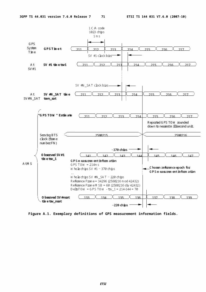
ADR
This field contains the ADR measurement measured by the MS for the particular satellite signal. This information can be used to compute the 3-D velocity or high-accuracy position of the MS. ADR measurements are converted into units of m by multiplying the ADR measurement by the nominal wavelength of the measured signal.
This field is optional and shall be included only when carrier phase measurements are requested-.
A.4 Assistance Data
A.4.1 GeneralThe Assistance Data is a RRLP component from the network to the MS. It is used by the network to provide assistance data to enable MS-based E-OTD or MS-based Assisted GPS capabilities in the MS and may be used to help support MS-assisted E-OTD and MS-assisted Assisted GPS. It contains the following elements.
Table A.11: Assistance Data component content
Element Type/Reference PresenceE-OTD Reference BTS for Assistance Data
E-OTD Reference BTS for Assistance Data 2.2.3
C
E-OTD Measurement Assistance Data
E-OTD Measurement Assistance Data 2.2.4
C
E-OTD Measurement Assistance Data for System Information List
E-OTD Measurement Assistance Data for System Information List 2.2.5
C
GPS Assistance Data GPS Assistance Data 4.2.4
C
GPS Time Assistance Measurement Request
GPS Time Assistance Measurement Request 4.2.4a
O
GPS Reference Time Uncertainty GPS Reference Time Uncertainty 4.2.4b
O
More Assistance Data To Be Sent More Assistance Data To Be Sent 4.2.5
C
Extended Reference Extended Reference 2.2.5
C
GANSS Assistance Data GANSS Assistance Data 4.2.6 CGANSS Carrier-Phase Measurement Request
GANSS Carrier-Phase Measurement Request 4.2.7
O
GANSS TOD - GSM Time Association Request
GANSS TOD - GSM Time Association Request 4.2.8
O
A.4.2 Elements
A.4.2.1 E-OTD Reference BTS for Assistance Data Element
This element is conditional. It is as described in sub-clause 2.2.3. If the network can provide assistance data, and data for E-OTD has been requested, this element is included.
A.4.2.2 E-OTD Measurement Assistance Data Element
This element is conditional. It is as described in sub-clause 2.2.4. If the network can provide assistance data, and data for E-OTD has been requested, this element is included.
A.4.2.3 E-OTD Measurement Assistance Data for System Information List Element
This element is conditional. It is as described in sub-clause 2.2.5. If the network can provide assistance data, and data for E-OTD has been requested, this element is included.
ETSI
ETSI TS 144 031 V7.6.0 (2007-10)713GPP TS 44.031 version 7.6.0 Release 7
A.4.2.4 GPS Assistance Data Element
The GPS Assistance Data element contains a single GPS assistance message that supports both MS-assisted and MS-based GPS methods. This element can contain one or more of the fields listed in table A.12 below, which support both MS-assisted and MS-based GPS methods. As table A.12 shows, all fields are optional.
Note that certain types of GPS Assistance data may be derived, wholly or partially, from other types of GPS Assistance data.
In addition, an Integrity Monitor (IM) shall detect unhealthy (e.g., failed/failing) satellites and also shall inform users of measurement quality in DGPS modes when satellites are healthy. Excessively large pseudo range errors, as evidenced by the magnitude of the corresponding DGPS correction, shall be used to detect failed satellites. Unhealthy satellites should be detected within 10 seconds of the occurrence of the satellite failure. When unhealthy (e.g., failed/failing) satellites are detected, the assistance and/or DGPS correction data shall not be supplied for these satellites. When the error in the IM computed position is excessive for solutions based upon healthy satellites only, DGPS users shall be informed of measurement quality through the supplied UDRE values. After bad satellites have been indicated in the Real Time Integrity field, if the satellites return to healthy condition for some period of time, the indications for them shall be removed from this field.
Table A.12: Fields in the GPS Assistance Data element
Parameter Presence RepetitionReference Time O YesReference Location O NoDGPS Corrections O YesNavigation Model O YesIonospheric Model O NoUTC Model O NoAlmanac O YesAcquisition Assistance O YesReal-Time Integrity O Yes
When RRLP pseudo-segmentation is used, Table A.12 indicates which parameters may be repeated in more than one RRLP segment in order to provide data for multiple satellites. When any such parameter appears in more than one segment, the following rules shall apply.
1. There shall be no repetition of data for the same satellite.
2. Optional and conditional elements in the parameter not associated with a particular satellite shall each appear in at most one RRLP segment.
3. Any mandatory element not associated with a particular satellite shall assume consistent values in the case of an element related to current GPS time and the same value otherwise.
4. The maximum number of satellites defined in sub-clause 5.1 for which data can be included for any parameter in one RRLP segment shall apply also when counted over all RRLP segments.
Reference Time
These fields specify the relationship between GPS time and air-interface timing of the BTS transmission in the reference cell. These fields occur once per message; some are mandatory and some are conditional, as shown in table A.14. Note that Reference Time may also be present within the Acquisition Assistance parameter. In such a case, the SMLC shall ensure consistency.
ETSI
ETSI TS 144 031 V7.6.0 (2007-10)723GPP TS 44.031 version 7.6.0 Release 7
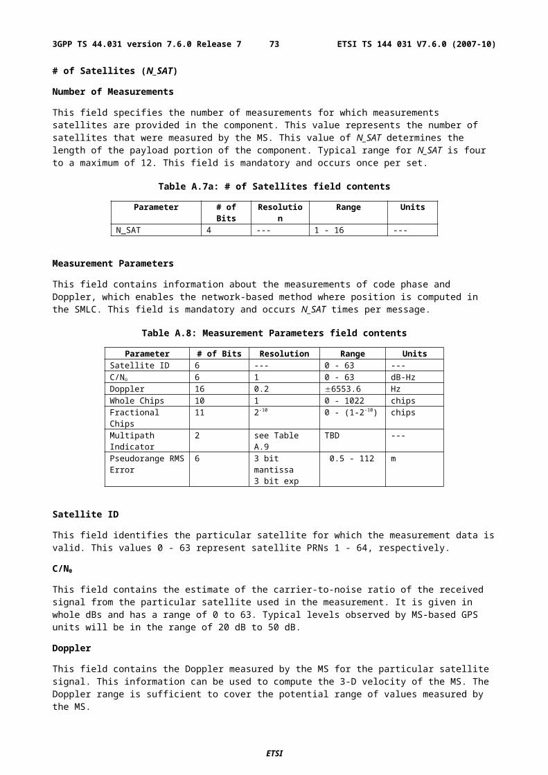
Table A.14: Reference Time (Fields occurring once per message)
Parameter # Bits Scale Factor
Range Units Incl.
GPS Week 10 1 0 - 1023 weeks MGPS TOW 23 0.08 0-604799.92 sec MBCCH Carrier 10 1 0 - 1023 --- O (note 1)BSIC 6 1 0 - 63 --- O (note 1)FNm 21 1 0 - (221-1) frames O (note 1)TN 3 1 0 - 7 timeslots O (note 1)BN 8 1 0 - 156 bits O (note 1)GPS TOW Assist 24*N_SAT --- ---- --- ONOTE 1: All of these fields shall be present together, or none of them shall be present.
GPS Week
This field specifies the GPS week number of the assistance being provided. GPS Week eliminates one-week ambiguities from the time of the GPS assistance. This field is mandatory.
GPS TOW
The GPS TOW (time-of-week) is a mandatory field and is specified with 80 msec resolution. When GSM Time Present is "1", GPS TOW and BCCH/BSIC/FNm/TN/BN IEs provide a valid relationship between GPS and GSM time, as seen at the approximate location of the MS, ie the propagation delay from BTS to MS shall be compensated for by the SMLC. Depending on implementation, the relation between GPS and GSM time may have varying accuracy. Therefore, the uncertainty of the timing relation may be provided in the optional field GPS Reference Time Uncertainty. If the propagation delay from BTS to MS is not accurately known, the SMLC shall use the best available approximation of the propagation delay and take the corresponding delay uncertainty into account in the calculation of the field GPS Reference Time Uncertainty. When GSM Time Present is "0", GPS TOW is an estimate of current GPS time of week at time of reception of the RRLP segment containing this data by the MS. The SMLC should achieve an accuracy of +/- 3 seconds for this estimate including allowing for the transmission delay between SMLC and MS of the RRLP segment containing GPS TOW. Note that the MS should further compensate GPS TOW for the time between the reception of the segment containing GPS TOW and the time when the GPS TOW field is used.
BCCH Carrier/BSIC/FNm/TN/BN
These fields specify the state of the GSM frame number, timeslot number, and bit number, respectively, of the reference BTS with the specified BCCH carrier and BSIC at the time that correspond to GPS TOW. The SMLC shall use the current serving BTS as the reference BTS. The frame number field is given modulo 221, i.e., the MSB of the GSM frame number is truncated. The MS shall interpret FNm as the most recent of the two possible frame numbers that FNm could represent. The target MS has the option of rejecting a GPS position request or GPS assistance data if the reference BTS is not the serving BTS.
GPS TOW Assist
This field contains several fields in the Telemetry (TLM) Word and Handover Word (HOW) that are currently being broadcast by the respective GPS satellites. Combining this information with GPS TOW enables the MS to know the entire 1.2-second (60-bit) pattern of TLM and HOW that is transmitted at the start of each six-second subframe by the particular GPS satellite. This field contains information for each of N_SAT satellites, and optional. The individual fields for each satellite in the message are shown in table A.15a.
Table A.15a: GPS TOW Assist (Fields occurring N_SAT times per message)
Parameter # Bits Scale Factor
Range Units Incl.
SatID 6 --- 0 - 63 --- MTLM Message 14 --- 0 - 16383 Bit field MAnti-Spoof 1 1 0 -1 Bit field MAlert 1 1 0 - 1 Bit field MTLM Reserved 2 --- 0 - 3 Bit field M
SatID
ETSI
ETSI TS 144 031 V7.6.0 (2007-10)733GPP TS 44.031 version 7.6.0 Release 7
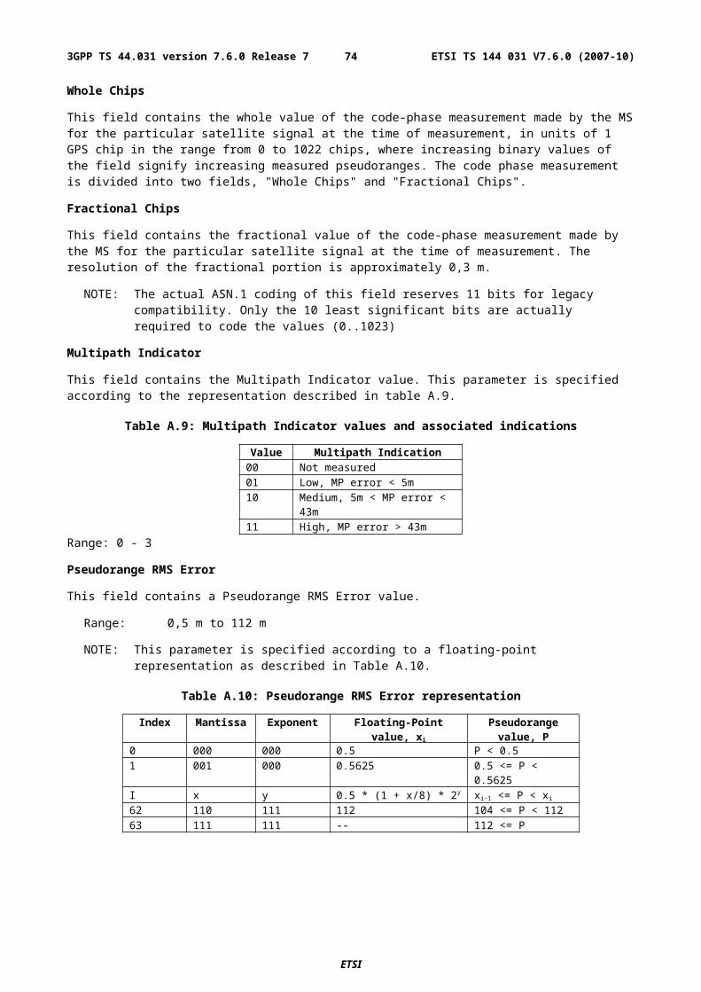
This field identifies the satellite for which the corrections are applicable. The values ranging from 0 to 63 represent satellite PRNs ranging from 1 to 64, respectively.
TLM Message
This field contains a 14-bit value representing the Telemetry Message (TLM) being broadcast by the GPS satellite identified by the particular SatID, with the MSB occurring first in the satellite transmission.
Anti-Spoof/Alert
These fields contain the Anti-Spoof and Alert flags that are being broadcast by the GPS satellite identified by SatID.
TLM Reserved
These fields contain the two reserved bits in the TLM Word being broadcast by the GPS satellite identified by SatID, with the MSB occurring first in the satellite transmission.
Reference Location
The Reference Location field contains a 3-D location (with uncertainty) specified as per 3GPP TS 23.032. The purpose of this field is to provide the MS with a priori knowledge of its location in order to improve GPS receiver performance. The allowed shape is 3-D location with uncertainty (ellipsoid point with altitude and uncertainty ellipsoid).
DGPS Corrections
These fields specify the DGPS corrections to be used by the MS. All fields are mandatory when DGPS Corrections are present in the GPS Assistance Data.
Table A.15: DGPS Corrections
Parameter # Bits Scale Factor Range Units Incl.The following fields occur once per message
GPS TOW 20 1 0 - 604799 sec MStatus/Health 3 1 0-7 --- MN_SAT 4 1 1-16 --- M
The following fields occur once per satellite (N_SAT times)SatID 6 --- 0 - 63 --- MIODE 8 --- 0 - 255 --- MUDRE 2 --- 0 - 3 --- MPRC 12 0.32 655.04 meters MRRC 8 0.032 4.064 meters/sec MDelta PRC2 8 --- --- --- MDelta RRC2 4 --- --- --- MDelta PRC3 8 --- --- --- MDelta RRC3 4 --- --- --- M
GPS TOW
This field indicates the baseline time for which the corrections are valid.
Status/Health
This field indicates the status of the differential corrections contained in the broadcast message. The values of this field and their respective meanings are shown below in table A.16.
ETSI
ETSI TS 144 031 V7.6.0 (2007-10)743GPP TS 44.031 version 7.6.0 Release 7
Table A.16: Values of Status/Health IE
Code Indication000 UDRE Scale Factor = 1.0001 UDRE Scale Factor = 0.75010 UDRE Scale Factor = 0.5011 UDRE Scale Factor = 0.3100 UDRE Scale Factor = 0.2101 UDRE Scale Factor = 0.1110 Reference Station Transmission Not
Monitored111 Data is invalid - disregard
The first six values in this field indicate valid differential corrections. When using the values described below, the "UDRE Scale Factor" value is applied to the UDRE values contained in the message. The purpose is to indicate an estimate in the amount of error in the corrections.
The value "110" indicates that the source of the differential corrections (e.g., reference station or external DGPS network) is currently not being monitored. The value "111" indicates that the corrections provided by the source are invalid, as judged by the source. In the later case, the message shall contain no corrections for individual satellites. Any MS that receives DGPS Corrections in a GPS Assistance Data IE shall contain the appropriate logic to properly interpret this condition and look for the next IE.
N_SAT
This field indicates the number of satellites for which differential corrections are available. Corrections for up to 16 satellites.
SatID
This field identifies the satellite for which the corrections are applicable. The values ranging from 0 to 63 represent satellite PRNs ranging from 1 to 64, respectively.
IODE
This IE is the sequence number for the ephemeris for the particular satellite. The MS can use this IE to determine if new ephemeris is used for calculating the corrections that are provided in the broadcast message. This eight-bit IE identifies a particular set of ephemeris data for a GPS satellite and may occupy the numerical range of [0, 255]. The transmitted IODE value will be different from any value transmitted by the GPS satellite during the preceding six hours. For more information about this field can be found from RTCM-SC104.
User Differential Range Error (UDRE)
This field provides an estimate of the uncertainty (1-) in the corrections for the particular satellite. The value in this field shall be multiplied by the UDRE Scale Factor in the common Corrections Status/Health field to determine the final UDRE estimate for the particular satellite. The meanings of the values for this field are described in table A.18.
Table A.18: Values of UDRE IE
Value Indication00 UDRE £ 1.0 m01 1.0 m < UDRE £ 4.0 m10 4.0 m < UDRE £ 8.0 m11 8.0 m < UDRE
Each UDRE value shall be adjusted based on the operation of an Integrity Monitor (IM) function which exists at the network (SMLC, GPS server, or reference GPS receiver itself). Positioning errors derived at the IM which are excessive relative to DGPS expected accuracy levels shall be used to scale the UDRE values to produce consistency.
Pseudo-Range Correction (PRC)
ETSI
ETSI TS 144 031 V7.6.0 (2007-10)753GPP TS 44.031 version 7.6.0 Release 7
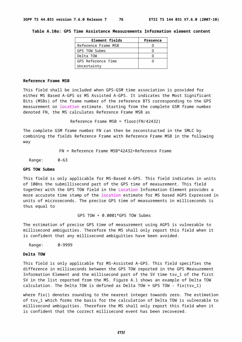
This field indicates the correction to the pseudorange for the particular satellite at the GPS Reference Time, t0. The value of this field is given in meters (m) and the resolution is 0.32, as shown in table A.15 above. The method of calculating this field is described in [9].
If the SMLC has received a request for GPS assistance data from an MS which included a request for the navigation models and DGPS (i.e., bit D and E are set to one in "Requested GPS Assistance Data, see 3GPP TS 49.031), the SMLC shall determine, for each satellite, if the navigation model stored by the MS is still suitable for use with DGPS corrections (also see navigation model update conditions right before Table A.19) and if so and if DGPS corrections are supported the SMLC should send DGPS corrections without including the navigation model.
The IODE value sent for a satellite shall always be the IODE value that corresponds to the navigation model for which the pseudo-range corrections are applicable.
The pseudo-range correction shall correspond to the available navigation model (the one already stored in and identified by the MS or the one included in the same procedure as the pseudo-range correction). The MS shall only use the PRC value when the IODE value received matches its available navigation model.
Pseudo-Range Rate Correction (RRC)
This field indicates the rate-of-change of the pseudorange correction for the particular satellite, using the satellite ephemeris identified by the IODE IE. The value of this field is given in meters per second (m/sec) and the resolution is 0.032, as shown in table A.15 above. For some time t1 > t0, the corrections for IODE are estimated by
PRC(t1, IODE) = PRC(t0, IODE) + RRC(t0, IODE)(t1 - t0) ,
and the MS uses this to correct the pseudorange it measures at t1, PRm(t1, IODE), by
PR(t1, IODE) = PRm(t1, IODE) + PRC(t1, IODE) .
The SMLC shall always send the RRC value that corresponds to the PRC value that it sends (see above for details). The MS shall only use the RRC value when the IODE value received matches its available navigation model.
Delta Pseudo-Range Correction 2 (Delta PRC2)
This IE is not used. The sender shall set it to zero and the receiver shall ignore it.
Delta Pseudo-Range Rate Correction 2 (Delta RRC2)
This IE is not used. The sender shall set it to zero and the receiver shall ignore it.
Delta Pseudo-Range Correction 3 (Delta PRC3)
This IE is not used. The sender shall set it to zero and the receiver shall ignore it.
Delta Pseudo-Range Rate Correction 3 (Delta RRC3)
This IE is not used. The sender shall set it to zero and the receiver shall ignore it.
Navigation Model
This set of fields contains information required to manage the transfer of precise navigation data to the GPS-capable MS. In response to a request from an MS for GPS assistance data, the SMLC shall determine whether to send the navigation model for a particular satellite to an MS based upon factors like the T-Toe limit specified by the MS and any request from the MS for DGPS (also see above). This information includes control bit fields as well as satellite ephemeris and clock corrections. The individual fields are given in Table A.19 below, and the conditions for their presence is discussed below.
ETSI
ETSI TS 144 031 V7.6.0 (2007-10)763GPP TS 44.031 version 7.6.0 Release 7
Table A.19: Navigation Model (per-satellite fields - (1) = Positive range only)
Parameter # Bits Scale Factor
Units Incl.
Navigation Model Flow Control (once per message)Num_Sats_Total 4(1) 1 --- M
Satellite and Format Identification (once per satellite)SatID 6(1) --- --- MSatellite Status 2 --- Boolean M
Satellite Navigation Model and Associated Bits (once per satellite)C/A or P on L2 2 --- Boolean CURA Index 4 --- Boolean CSV Health 6 --- Boolean CIODC 10(1) --- --- CL2 P Data Flag 1 --- Boolean CSF 1 Reserved 87 --- --- CTGD 8 2-31 sec Ctoc 16(1) 24 sec Caf2 8 2-55 sec/sec2 Caf1 16 2-43 sec/sec Caf0 22 2-31 sec CCrs 16 2-5 meters Cn 16 2-43 semi-circles/sec CM0 32 2-31 semi-circles CCuc 16 2-29 radians Ce 32(1) 2-33 --- CCus 16 2-29 radians C(A)1/2 32(1) 2-19 meters1/2 Ctoe 16(1) 24 sec CFit Interval Flag 1 --- Boolean CAODO 5 900 sec CCic 16 2-29 radians COMEGA0 32 2-31 semi-circles CCis 16 2-29 radians Ci0 32 2-31 semi-circles CCrc 16 2-5 meters C 32 2-31 semi-circles COMEGAdot 24 2-43 semi-circles/sec CIdot 14 2-43 semi-circles/sec C
Num_Sats_Total
This field specifies the number of satellites that are included in the provided Navigation Model. A range of 1-16 is available. This field is mandatory when the Navigation Model field is included in the message.
SatID
This field identifies the satellite for which the assistance is applicable. This value is the same as the PRN number provided in the navigation message transmitted by the particular satellite. The range is 0 to 63, with 0-31 indicating GPS satellites 1-32, respectively, and 32-63 indicating satellites in future augmentation systems (e.g., WAAS or EGNOS). This field is mandatory for each included satellite.
Satellite Status
This field is a two-bit value that indicates the status of the Navigation Model for the particular satellite specified by SatID. This field is mandatory for each included satellite. The MS shall interpret the combinations of the two bits as follows.
ETSI
ETSI TS 144 031 V7.6.0 (2007-10)773GPP TS 44.031 version 7.6.0 Release 7
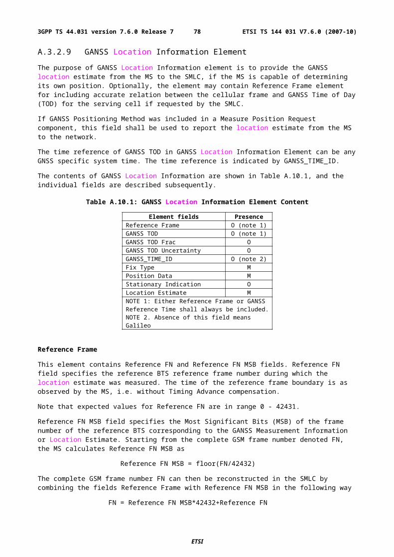
Table A.20: Satellite Status (per-satellite field)
MSB LSB Interpretation0 0 New satellite, new Navigation Model0 1 Existing satellite, same Navigation Model1 0 Existing satellite, new Navigation Model1 1 Reserved
This Satellite Navigation Model and associated bit fields include the parameters that accurately model the orbit and clock state of the particular satellite. For the particular satellite, these fields are conditional based on the value of Satellite Status for that satellite. The fields are absent when Satellite Status is "01", and present for all other values. The format for the ephemeris, clock corrections, and associate bits are specified in ICD-GPS-200.
Ionospheric Model
The Ionospheric Model contains fields needed to model the propagation delays of the GPS signals through the ionosphere. The information elements in this field are shown in table A.21. Proper use of these fields allows a single-frequency GPS receiver to remove approximately 50 % of the ionospheric delay from the range measurements. The Ionospheric Model is valid for the entire constellation and changes slowly relative to the Navigation Model. All of the fields must be included when Ionospheric Model is present.
Table A.21: Ionospheric Model (occurs once per message, when present)
Parameter # Bits Scale Factor Units Incl.0 8 2-30 seconds C1 8 2-27 sec/semi-circle C2 8 2-24 sec/(semi-circle)2 C3 8 2-24 sec/(semi-circle)3 C0 8 211 seconds C1 8 214 sec/semi-circle C2 8 216 sec/(semi-circle)2 C3 8 216 sec/(semi-circle)3 C
UTC Model
The UTC Model field contains a set of parameters needed to relate GPS time to Universal Time Coordinate (UTC). All of the fields in the UTC Model are mandatory when the field is present.
Table A.22: UTC Model (occurs once per message,when present per-satellite fields - (1) = Positive range only)
Parameter # Bits Scale Factor Units Incl.A1 24 2-50 sec/sec CA0 32 2-30 seconds Ctot
(1) 8 212 seconds CWNt
(1) 8 1 weeks CtLS 8 1 seconds CWNLSF
(1) 8 1 weeks CDN 8 1 days CtLSF 8 1 seconds C
ETSI
ETSI TS 144 031 V7.6.0 (2007-10)783GPP TS 44.031 version 7.6.0 Release 7
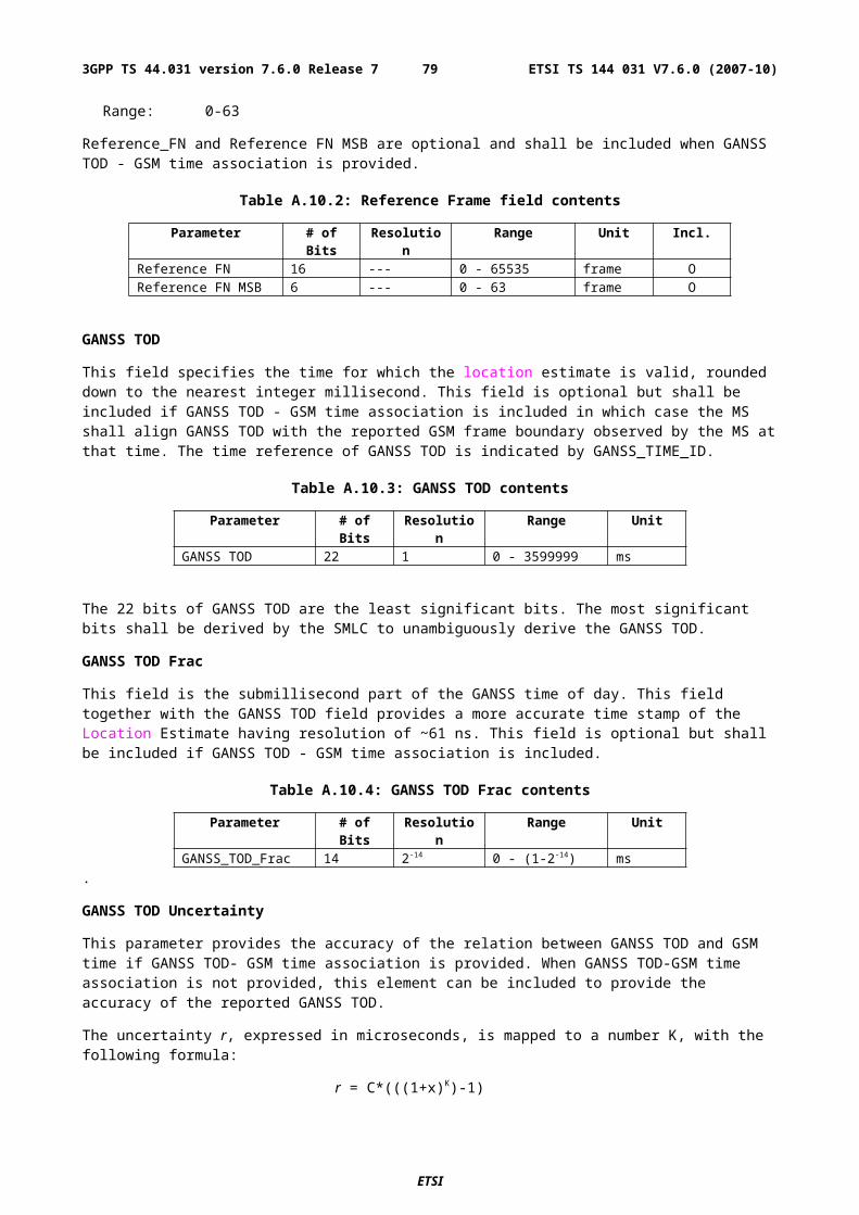
Almanac
These fields specify the coarse, long-term model of the satellite positions and clocks. These fields are given in table A.23. With one exception (i), these parameters are a subset of the ephemeris and clock correction parameters in the Navigation Model, although with reduced resolution and accuracy. The almanac model is useful for receiver tasks that require coarse accuracy, such as determining satellite visibility. The model is valid for up to one year, typically. Since it is a long-term model, the field should be provided for all satellites in the GPS constellation. All fields in the Almanac are mandatory when the Almanac is present. The fields toa and WNa specify the GPS time-of-week and week number, respectively, that are the reference points for the Almanac parameters.
The Almanac also is useful as an acquisition aid for network-based GPS methods. Given a recent Almanac (< 3-4 weeks old), the MS only needs Reference Time and Reference Location information to quickly acquire the signals and return measurements to the network.
The Almanac also contains information about the health of that satellite as described in ICD-GPS-200. If this Alamanc has been captured from the satellite signal, the SV Health field represents the predicted satellite health at the time the GPS control segment uploaded the Almanac to the satellite. According to ICD-GPS-200, this health information may differ from the SV Health field in the Navigation Model (table A.19) due to different upload times.
The parameters Num_Sats_Total and SatID shall be interpreted in the same manner as described under table A19.
Table A.23: Almanac (per-satellite fields - (1) = Positive range only)
Parameter # Bits Scale Factor Units Incl.The following fields occur once per message
Num_Sats_Total 6(1) 1 --- MWNa 8(1) 1 weeks M
The following fields occur once per satelliteSatID 6(1) --- --- Me(1) 16 2-21 dimensionless Mtoa
(1) 8 212 sec Mi 16 2-19 semi-circles MOMEGADOT 16 2-38 semi-circles/sec MSV Health 8 --- Boolean MA1/2(1) 24 2-11 meters1/2 MOMEGA0 24 2-23 semi-circles M 24 2-23 semi-circles MM0 24 2-23 semi-circles Maf0 11 2-20 seconds Maf1 11 2-38 sec/sec M
Acquisition Assistance
The Acquisition Assistance field of the GPS Assistance Data Information Element contains parameters that enable fast acquisition of the GPS signals in network-based GPS positioning. Essentially, these parameters describe the range and derivatives from respective satellites to the Reference Location at the Reference Time. Table A.24 illustrates the assistance data occurring once per message and table A.25 illustrates the assistance data occurring per number of satellites for which acquisition assistance is being provided. Figure A.2 illustrates the relation between some of the fields.
This field is optional. The field would probably appear when the Method Type field of the Positioning Instructions IE is set to 0 (MS-Assisted) and the Positioning Methods field of the Position Instructions IE is set to 1 (GPS) or 2 (GPS or E-OTD).
ETSI
ETSI TS 144 031 V7.6.0 (2007-10)793GPP TS 44.031 version 7.6.0 Release 7
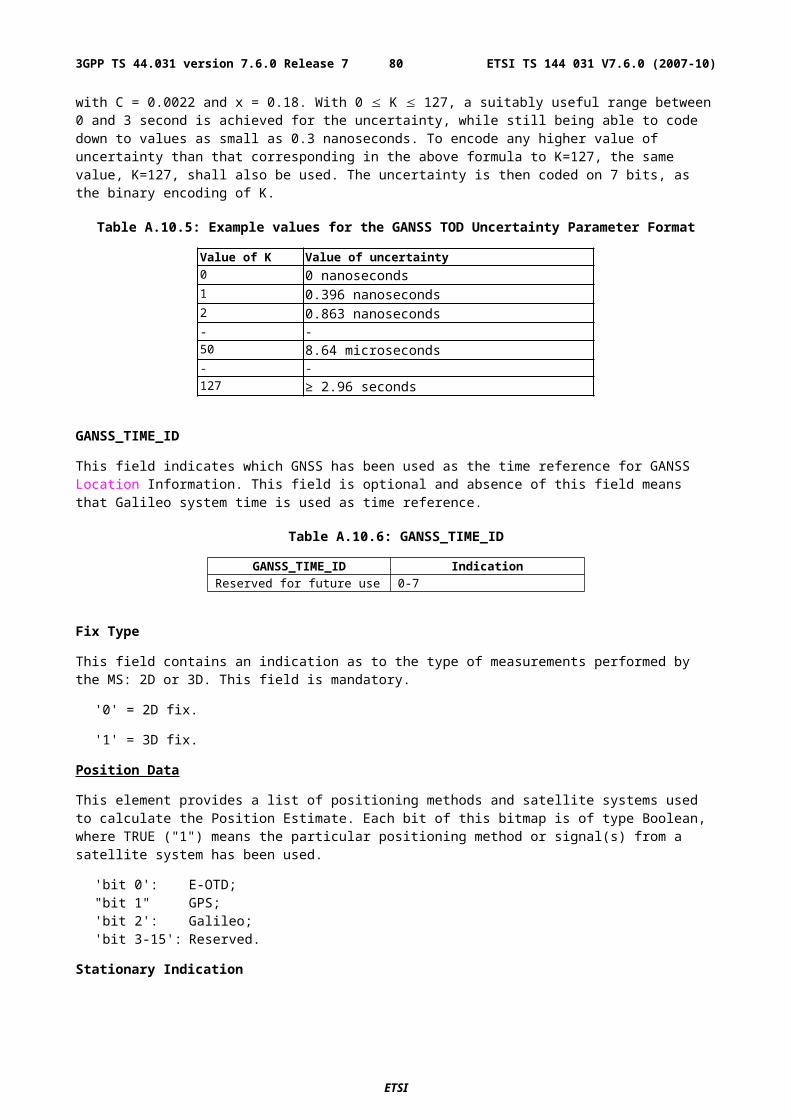
Table A.24: GPS Acquisition Assist - Parameters appearing once per message
Parameter Range Bits Resolution Incl. NotesNumber of Satellites 0 - 15 4 MReference Time GPS TOW 0 -604799.92 sec 23 0.08 sec M
BCCH Carrier 0 - 1023 10 O1
BSIC 0 - 63 6 O1
Frame # 0 - 2097151 21 O1
Timeslots # 0 - 7 3 O1
Bit # 0 - 156 8 O1
NOTE: All of these field shall be present together, or none of them shall be present.
Table A.25: GPS Acquisition Assist - Parameters appearing [number of satellites] times per message
Parameter Range Bits Resolution Incl. NotesSVID/PRNID 1 - 64 (0 - 63 ) 6 MDoppler (0th order term) -5,120 Hz to 5,117.5 Hz 12 2.5 Hz MDoppler (1st order term) -1.0 - 0.5 Hz/sec. 6 1/42 Hz/sec. O1
Doppler Uncertainty 12.5 Hz - 200 Hz [2-n(200) Hz, n = 0 - 4]
3 O1
Code Phase 0 - 1022 chips 10 1 chip MInteger Code Phase 0-19 5 1 C/A period MGPS Bit number 0 - 3 2 MCode Phase Search Window 1 - 192 chips 4 MAzimuth 0 - 348.75 deg 5 11.25 deg O2
Elevation 0 - 78.75 deg 3 11.25 deg O2
NOTE 1: Both of these fields shall be present together, or none of them shall be present.NOTE 2: Both of these fields shall be present together, or none of them shall be present.
ETSI
ETSI TS 144 031 V7.6.0 (2007-10)803GPP TS 44.031 version 7.6.0 Release 7
Figure A.2. Exemplary calculations of Acquisition Assistance fields.
This field indicates whether or not angle information is present in this message. The MS shall interpret a value of "1" to mean that angle (Azimuth and Elevation) information is present, and "0" to mean that it is not provided. This field is mandatory.
Number of Satellites
This field contains the number of satellites identified in this information element. This field is mandatory.
Range: 0 - 15
Reference Time
The Reference Time field of the GPS Acquisition Assistance Data IE specifies the relationship between GPS time and air-interface timing of the BTS transmission in the reference cell.
GPS TOW subfield specifies the GPS TOW for which the location estimate is valid. When the parameters BCCH Carrier/BSIC/Frame #/Timeslots #/Bit # are present, together with GPSTOW they provide a valid relationship between GPS and GSM time, as seen at the approximate location of the MS, ie the propagation delay from BTS to MS shall be compensated for by the SMLC. Depending on implementation, the relation between GPS and GSM time may have varying accuracy. The uncertainty of the timing relation may be provided in the optional field GPS Reference Time Uncertainty. If the propagation delay from BTS to MS is not accurately known, the SMLC shall use the best available approximation of the propagation delay and take the corresponding delay uncertainty into account in the calculation of the field GPS Reference Time Uncertainty. GPS TOW is mandatory when the GPS Acquisition Assistance Data
ETSI
ETSI TS 144 031 V7.6.0 (2007-10)813GPP TS 44.031 version 7.6.0 Release 7
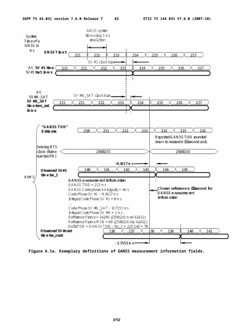
Information Element is included. When the GSM time parameters are not present the GPS TOW is an estimate of current GPS time of week at time of reception of the RRLP segment containing the GPS TOW by the MS. The SMLC should achieve an accuracy of +/- 3 seconds for this estimate including allowing for the transmission delay between SMLC and MS of the RRLP segment containing GPS TOW. Note that the MS should further compensate GPS TOW for the time between the reception of the segment containing GPS TOW and the time when the GPS TOW field is used.
Range: 0 - 604799.92 sec
The BCCH Carrier # and BSIC subfields specify the reference cell for which GSM timing is provided. These subfields are optional when the GPS Acquisition Assistance Data Information Element is included. If included, the SMLC shall set the reference cell to the current serving cell. A target MS has the option of rejecting a GPS position request or GPS assistance data if the reference cell is not the serving cell.
The Frame # subfield specifies the GSM frame number of the BTS transmissions for the reference cell that occur at the given GPS TOW. This subfield is optional when the GPS Acquisition Assistance Data Information Element is included.
Range: 0 - 2097151
The Timeslots # subfield specifies the GSM timeslot of the BTS transmissions for the reference cell that occur at the given GPS TOW. This subfield is optional when the GPS Acquisition Assistance Data Information Element is included.
Range: 0 - 7
The Bit # subfield specifies the GSM and bit number of the BTS transmissions for the reference cell that occur at the given GPS TOW. This subfield is optional when the GPS Acquisition Assistance Data Information Element is included.
Range: 0 - 156
SVID/PRNID
This field identifies the particular satellite for which the measurement data is supplied. This value is the same as the PRN number provided in the navigation message transmitted by the particular satellite.
The range is 0 to 63, where SVID = PRNID - 1
Doppler (0th order term)
This field contains the Doppler (0th order term) value. A positive value defines the increase in satellite signal frequency due to velocity towards the MS. A negative value defines the decrease in satellite signal frequency due to velocity away from the MS. This field is mandatory.
Range: 5,120 Hz to 5,117.5 Hz
Doppler (1st order term)
This field contains the Doppler (1st order term) value. A positive value defines the rate of increase in satellite signal frequency due to acceleration towards the MS. A negative value defines the rate of decrease in satellite signal frequency due to acceleration away from the MS. This field is optional.
Range: -1,0 Hz to 0,5 Hz / s
Doppler Uncertainty
This field contains the Doppler uncertainty value. It is defined such that the Doppler experienced by a stationary MS is in the range "Doppler Doppler Uncertainty" to "Doppler Doppler Uncertainty". This field is optional. If Doppler Uncertainty (together with Doppler 1st order term) is omitted, the terminal shall interpret Doppler Uncertainty as greater than +/-200 Hz.
Permitted Values: 12.5 Hz, 25 Hz, 50 Hz, 100 Hz, 200 Hz as encoded by an integer n in the range 0-4 according to the formula in Table A.25
Code Phase
This field contains code phase, in units of 1 GPS chip, in the range from 0 to 1022 GPS chips, where increasing binary values of the field signify increasing predicted pseudoranges, as seen by a receiver at the Reference Location at the time GPS TOW. The Reference Location would typically be an apriori estimate of the MS location. This field is mandatory.
ETSI
ETSI TS 144 031 V7.6.0 (2007-10)823GPP TS 44.031 version 7.6.0 Release 7
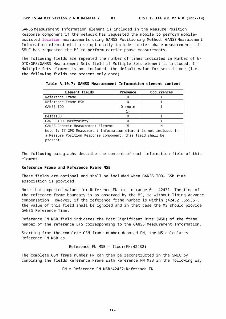
Range: 0-1022 chips
Integer Code Phase
This field contains integer code phase, i.e. the number of the code periods that have elapsed since the latest GPS bit boundary, in units of C/A code period, as seen by a receiver at the Reference Location at the time GPS TOW. This field is mandatory.
Range: 0-19
GPS Bit Number
This field contains GPS bit number (expressed modulo 4) currently being transmitted at the time GPS TOW, as seen by a receiver at the Reference Location. This field is mandatory.
Range: 0-3
Code Phase Search Window
This field contains the code phase search window. The code phase search window accounts for the uncertainty in the estimated MS location but not any uncertainty in GPS TOW. It is defined such that the expected code phase is in the range "Code Phase - Code Phase Search Window" to "Code Phase + Code Phase Search Window". This field is mandatory.
Range: 0-15 (i.e. 1-512 chips according to following table)
Table A.26: Code Phase Search Window Parameter Format
CODE_PHASE_WIN Code Phase Search Window (GPS chips)
'0000' 512'0001' 1'0010' 2'0011' 3'0100' 4'0101' 6'0110' 8'0111' 12'1000' 16'1001' 24'1010' 32'1011' 48'1100' 64'1101' 96'1110' 128'1111' 192
Azimuth
This field contains the azimuth angle. An angle of x degrees means the satellite azimuth a is in the range (x £ a < x+11.25) degrees. This field is optional.
Range: 0 - 348.75 degrees.
Elevation
This field contains the elevation angle. An angle of y degrees means the satellite elevation e is in the range (y £ e < y+11.25) degrees except for y = 78.75 where the range is extended to include 90 degrees. This field is optional.
Range: 0 - 78.75 degrees
Real-Time Integrity
The Real-Time Integrity field of the GPS Assistance Data Information Element contains parameters that describe the real-time status of the GPS constellation. Primarily intended for non-differential applications, the real-time integrity of
ETSI
ETSI TS 144 031 V7.6.0 (2007-10)833GPP TS 44.031 version 7.6.0 Release 7
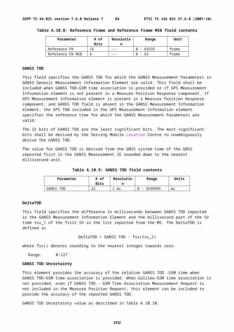
the satellite constellation is of importance as there is no differential correction data by which the mobile can determine the soundness of each satellite signal. The Real-Time GPS Satellite Integrity data communicates the health of the constellation to the mobile in real-time. The format is shown in table A.29. The SMLC shall always transmit the Real Time Integrity field with the current list of unhealthy satellites, for any A-GPS positioning attempt and whenever A-GPS assistance data is sent. If the number of bad satellites (NBS) is zero, then the Real Time Integrity field shall be omitted. When the Extended Reference IE is included in the RRLP Measure Position Request message or in the RRLP Assistance Data message, then the MS shall interpret the absence of a Real Time Integrity field in the assistance data provided by the SMLC to mean that NBS is zero. If the Extended Reference IE is not present, this interpretation applies when the assistance data is provided by the SMLC following a previous request of the MS for Real Time Integrity data.
Table A.29: Real-Time Integrity - Parameters appearing NBS times
Parameter # Bits Scale Factor Range Units Incl.Bad_SVID 6 1 0-63 --- C
NBS (Number of Bad Satellites)
The NBS value indicates the number of satellite ID's that follow that the user should not use at this time in a fix. This NBS value is determined from the Bad_SVID list.
Bad_SVID
This six bit field appears NBS times, and indicates the SVID of satellites that should not be used for fix by the user at this time. The values ranging from 0 to 63 represent satellite PRNs ranging from 1 to 64, respectively.
A.4.2.4a GPS Time Assistance Measurement Request Element
This element is optional and controls if the MS should return GPS time assistance measurements or not to the SMLC. The inclusion of this parameter implies use of measure Position Request The description is found in sub-chapter 2.2.4a.
A.4.2.4b GPS Reference Time Uncertainty Element
This element is conditional and provides the accuracy of the relation GPS and GSM time in the Acquisition Assistance in GPS Assistance Data Element. The interval, range and treatment is as described in sub-clause 2.2.4b.
A.4.2.5 More Assistance Data To Be Sent Element
This element is set by the SMLC to indicate to the MS if more Assistance Data components or a the final RRLP Measure Position Request component will be sent in the current procedure in order to deliver the entire set of assistance data.
A.4.2.6 GANSS Assistance Data
The GANSS Assistance Data consists of two or more data elements depending on the number of GNSS constellations included in the GANSS Assistance Data. GANSS Assistance Data elements are of two different types: GANSS Common Assistance Data and GANSS Generic Assistance Data. GANSS Common Assistance Data element is included at most only once and it contains Information Elements that can be used with any GNSS constellation. GANSS Generic Assistance data element can be included multiple times depending on the number of GNSS constellations supported in the GANSS Assistance Data. One GANSS Generic Assistance Data element contains Information Elements dedicated only for one specific GNSS constellation at a time. If two or more constellations are supported, GANSS Generic Assistance Data is given for each constellation separately.
The fields in GANSS Assistance Data are listed in Table A.30 below. As table A.30 shows, all fields are optional.
Table A.30: Fields in the GANSS Assistance Data element
Element Presence RepetitionGANSS Common Assistance Data O NoGANSS Generic Assistance Data O Yes
ETSI
ETSI TS 144 031 V7.6.0 (2007-10)843GPP TS 44.031 version 7.6.0 Release 7
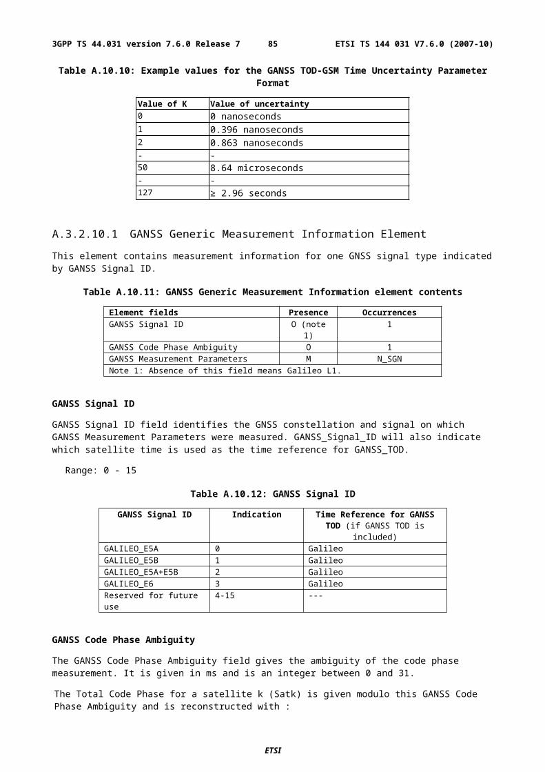
When RRLP pseudo-segmentation is used, Tables A.30, A.31 and A.39 indicate which parameters may be repeated in more than one RRLP segment in order to provide data for multiple constellations, satellites or signals. When any such parameter appears in more than one segment, the following rules shall apply.
1. There shall be no repetition of the same data for the same constellation, satellite or signal even though there might be multiple realizations of the IEs for the same constellation, satellite or signal. For example, DGANSS corrections may occur multiple times for the same satellite.
2. Optional and conditional elements in the parameter not associated with a particular constellation, satellite or signal shall each appear in at most one RRLP segment.
3. Any mandatory element not associated with a particular constellation, satellite or signal shall assume consistent values in the case of an element related to current reference time and the same value otherwise.
4. The maximum number of constellations, satellites or signals defined in sub-clause 5.1 for which data can be included for any parameter in one RRLP segment shall apply also when counted over all RRLP segments.
A.4.2.6.1 GANSS Common Assistance Data
GANSS Common Assistance Data element contains GNSS constellation independent information elements that can be applied on any specific GNSS or on a combination of GNSS. GANSS Common Assistance Data fields are included in GANSS Assistance Data only once. This element can contain one or more of the fields listed in table A.31 below. As Table A.31 shows, all fields are optional.
Table A.31: GANSS Common Assistance Data content
Field Presence RepetitionGANSS Reference Time O NoGANSS Reference Location O NoGANSS Ionospheric Model O No
GANSS Reference Time
This field specifies the GANSS Time Of Day (TOD) with uncertainty and relationship between GANSS Reference Time and air-interface timing of the BTS transmission in the reference cell. These fields occur once per message; some are mandatory and some are optional, as shown in Table A.33.
When GANSS TOD -GSM Time association is present, GANSS TOD and BCCH/BSIC/FNm/TN/BN IEs provide a valid relationship between GANSS TOD and GSM time, as seen at the approximate location of the MS, i.e. the propagation delay from BTS to MS shall be compensated for by the SMLC. Depending on implementation, the relation between GANSS TOD and GSM time may have varying accuracy. Therefore, the uncertainty of the timing relation is provided in GANSS TOD Uncertainty. If the propagation delay from BTS to MS is not accurately known, the SMLC shall use the best available approximation of the propagation delay and take the corresponding delay uncertainty into account in the calculation of the field GANSS TOD Uncertainty. When GANSS TOD -GSM Time association is not present, GANSS TOD is an estimate of current GANSS TOD at time of reception of the RRLP segment containing this data by the MS. The SMLC should achieve an accuracy of +/- 3 seconds for this estimate including allowing for the transmission delay between SMLC and MS of the RRLP segment containing GANSS TOD. Note that the MS should further compensate GANSS TOD for the time between the reception of the segment containing GANSS TOD and the time when the GANSS TOD field is used.
ETSI
ETSI TS 144 031 V7.6.0 (2007-10)853GPP TS 44.031 version 7.6.0 Release 7
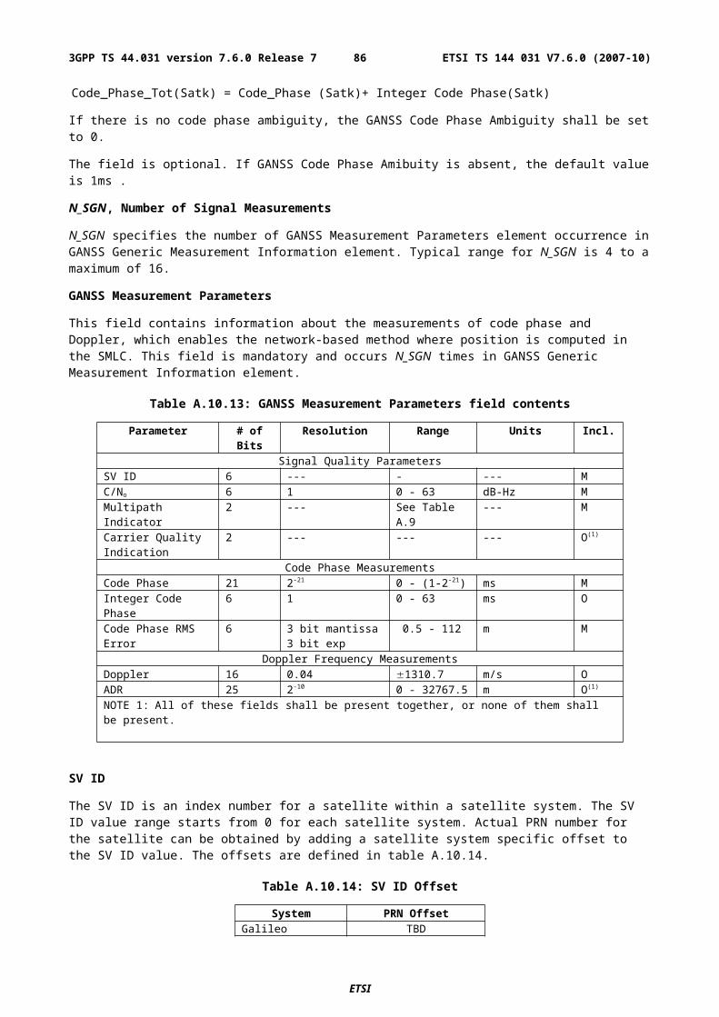
Table A.33: GANSS Reference Time
Parameter # Bits Scale Factor Range Units Incl.GANSS Reference Time Information (once per message)
GANSS Day 13 1 0 - 8191 day OGANSS TOD 17 1 0 - 86399 sec MGANSS TOD Uncertainty 7 - 0…127 - OGANSS_TIME_ID 3 --- --- --- O (note 3)
GANSS TOD - GSM Time Association (once per message)BCCH Carrier 10 1 0 - 1023 --- O (note 1)BSIC 6 1 0 - 63 --- O (note 1)FNm 21 1 0 - (221-1) frames O (note 1)TN 3 1 0 - 7 timeslots O (note 1)BN 8 1 0 - 156 bits O (note 1)FN1 7 2-30 -5.9605e-8 -
+5.8673e-8sec/sec O (note 2)
NOTE 1: All of these fields shall be present together, or none of them shall be present.NOTE 2: This field can be optionally included if GANSS TOD - GSM Time association is present.NOTE 3. Absence of this field means Galileo system time.
GANSS Day
This field specifies the sequential number of days from the origin of the GNSS system time indicated by GANSS_TIME_ID modulo 8192 days (about 22 years). This field is optional.
Range: 0 - 8191 days
GANSS TOD
Integer number of GANSS TOD seconds within the current day.
Range: 0 - 86399 s.
GANSS TOD Uncertainty
GANSS TOD uncertainty value as described in 3.2.9. This field is optional.
GANSS_TIME_ID
This field specifies the GNSS system time used in GANSS Reference Time.
Table A.34: GANSS_TIME_ID
GANSS_TIME_ID IndicationReserved for future use 0 - 7
BCCH Carrier/BSIC/FNm/TN/BN/FN1
These fields specify the state of the GSM frame number, respectively, of the reference BTS with the specified BCCH carrier and BSIC at the time that correspond to GANSS TOD. Also, the drift rate of the frame timing, FN1, with respect to the GANSS TOD is optionally given. The SMLC shall use the current serving BTS as the reference BTS. The target MS has the option of rejecting a GANSS position request or GANSS assistance data if the reference BTS is not the serving BTS. If FNm field is present in the assistance, cellular time parameters FNm/TN/BN shall be aligned with the integer GANSS TOD second given in GANSS TOD field.
GANSS Reference Location
The Reference Location field contains a 3-D location (with uncertainty) specified as per 3GPP TS 23.032. The purpose of this field is to provide the MS with a priori knowledge of its location in order to improve GNSS receiver performance. The allowed shape is 3-D location with uncertainty (ellipsoid point with altitude and uncertainty ellipsoid).
NOTE: If GPS Assistance Data component is present as well, the SMLC should include the Reference Location either in the GPS Assistance Data or GANSS Common Assistance Data element.
ETSI
ETSI TS 144 031 V7.6.0 (2007-10)863GPP TS 44.031 version 7.6.0 Release 7
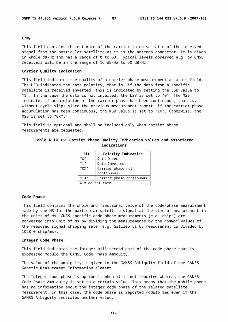
GANSS Ionospheric Model
GANSS Ionospheric Model contains parameters to model the propagation delay of the GNSS signals through the ionosphere. The information elements in this field are shown in Table A.35. Proper use of these fields allows a single-frequency GNSS receiver to remove the ionospheric delay from the pseudorange measurements.
Table A.35: GANSS Ionospheric Model
Parameter # Bits Scale Factor Units Incl.GANSS Ionosphere Model Parameters
ai0 12 --- --- Mai1 12 --- --- Mai2 12 --- --- M
GANSS Ionosphere Regional Storm FlagsStorm Flag 1 1 --- --- O (note 1)Storm Flag 2 1 --- --- O (note 1)Storm Flag 3 1 --- --- O (note 1)Storm Flag 4 1 --- --- O (note 1)Storm Flag 5 1 --- --- O (note 1)NOTE 1: All of these fields shall be present together, or none of them shall be present.
GANSS Ionosphere Parameters
The ionosphere model parameters are used to estimate the ionospheric distortions on pseudoranges as described in [11] on page 71.
GANSS Ionosphere Regional Storm Flags
Ionosphere storm flags (1,…,5) are optionally provided separately for five different regions as described in [11] on page 71.
A.4.2.6.2 GANSS Generic Assistance Data
GANSS Generic Assistance data elements contain Information Elements that are applied on one specific GNSS at a time indicated by GANSS_ID. The format of the IE"s remains the same regardless of the GANSS; only the values of the parameters and inclusion of certain optional fields will vary.
GANSS Generic Assistance Data is repeated for each GNSS included in GANSS Assistance Data. GANSS Generic Assistance Data can contain one or more of the elements listed in Table A.39 below. As Table A.39 shows, all fields are optional.
Table A.39: GANSS Generic Assistance Data content
Element Presence RepetitionGANSS ID O (note 1) NoGANSS Time Model O YesDGANSS Corrections O YesGANSS Navigation Model O YesGANSS Real-Time Integrity O YesGANSS Data Bit Assistance O YesGANSS Reference Measurement Information O YesGANSS Almanac Model O YesGANSS UTC Model O NoNote 1: Absence of this field means Galileo.
GANSS_ID
This field indicates the GNSS for which the following assistance data IE"s in GANSS Generic Assistance Data element are dedicated. The supported GANSS are listed in Table A.40. Absence of this field indicates Galileo.
Range: 0 - 7
ETSI
ETSI TS 144 031 V7.6.0 (2007-10)873GPP TS 44.031 version 7.6.0 Release 7
Table A.40: GANSS_ID
GANSS_ID IndicationReserved for future use 0-7
GANSS Time Model
This field specifies a model to relate GNSS system time to a selected time reference. GNSS Time Offset ID (GNSS_TO_ID) identifies the GNSS for which the relation is provided.
The SMLC may send multiple GANSS Time Models for a specific GNSS depending on the number of the allowed satellite systems in GANSS Position Method. For example, the SMLC may send two GANSS Time Models for Galileo to give the relations between Galileo and two GNSS system times.
Table A.41: GANSS Time Model
Parameter # Bits Scale Factor Range Units Incl.GANSS Time Model Reference Time
16 24 0 - 604784 s M
TA0 16 2-35 sec MTA1 13 2-51 sec/sec OTA2 7 2-68 sec/sec2 OGNSS_TO_ID 3 --- --- --- MWeek Number 13 1 0 - 8191 week O
GANSS Time Model Reference Time
This field specifies the reference time of week for GANSS Time Model and it is given in GNSS specific system time..
Range: 0 - 255 h
TA0/TA1/TA2
These fields specify the GANSS Time Model for a specific GNSS system by constant and first and second order terms of polynomial. The first and second order terms are optional.
GNSS_TO_ID
This field specifies GNSS Time Offset ID. GANSS Time Model contains parameters to convert GNSS System Time from the system indicated by GANSS_ID to GNSS System Time indicated by GNSS_TO_ID. The conversion is defined e.g. in [11].
Table A.42: GNSS_TO_ID
GNSS_TO_ID IndicationGPS 0GALILEO 1Reserved for future use 2-7
Week Number
This field specifies the reference week of GANSS Time Model given in GNSS specific system time. This field is optional.
DGANSS Corrections
These fields specify the DGANSS corrections to be used by the MS.
ETSI
ETSI TS 144 031 V7.6.0 (2007-10)883GPP TS 44.031 version 7.6.0 Release 7
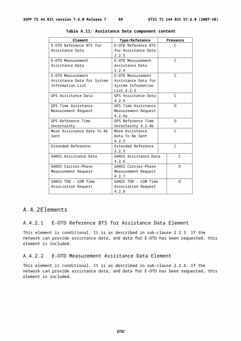
Table A.43: DGANSS Corrections
Parameter # Bits Scale Factor Range Units Incl.The following fields occur once per message
DGANSS Reference Time 7 30 0 - 3570 seconds MThe following fields occur once per GANSS signal type (N_SGN_TYPE times)
GANSS_Signal_ID 2 --- --- --- O (note 1)Status/Health 3 1 0 - 7 --- MN_SGN 4 1 1 - 16 --- M
The following fields occur once per GANSS Signal (N_SGN times)SV_ID 6 --- 0…63 --- MIOD 10 --- --- --- MUDRE 2 --- 0 - 3 --- MPRC 12 0.32 655.04 meters MRRC 8 0.032 4.064 meters/sec MNote 1: Absence of this field means Galileo L1 OS if GANSS_ID refers to Galileo.
DGANSS Reference Time
This field indicates the baseline time for which the DGANSS corrections are valid as modulo 3600 s. DGANSS Reference Time is given in GNSS system time.
Range: 0 - 3600 s
N_SGN_TYPE
This field indicates the number of GNSS signal types included in DGANSS IE.
GANSS_Signal_ID
DGANSS corrections are ordered per GNSS signal type identified by GANSS_Signal_ID. Absence of GANSS_Signal_ID indicates Galileo L1 OS signal in Galileo case. The supported signals for Galileo are listed in Table A.43.1.
Table A.43.1: GANSS Signal Ids for Galileo
GANSS Signal ID IndicationGALILEO_E5A 0GALILEO_E5B 1GALILEO E5A + E5B 2GALILEO_E6 3
Status/Health
This field indicates the status of the differential corrections contained in the broadcast message. The values of this field and their respective meanings are shown below in Table A.44.
Table A.44: Values of Status/Health IE
Code Indication000 UDRE Scale Factor = 1.0001 UDRE Scale Factor = 0.75010 UDRE Scale Factor = 0.5011 UDRE Scale Factor = 0.3100 UDRE Scale Factor = 0.2101 UDRE Scale Factor = 0.1110 Reference Station Transmission Not
Monitored111 Data is invalid - disregard
The first six values in this field indicate valid differential corrections. When using the values described below, the "UDRE Scale Factor" value is applied to the UDRE values contained in the message. The purpose is to indicate an estimate in the amount of error in the corrections.
ETSI
ETSI TS 144 031 V7.6.0 (2007-10)893GPP TS 44.031 version 7.6.0 Release 7
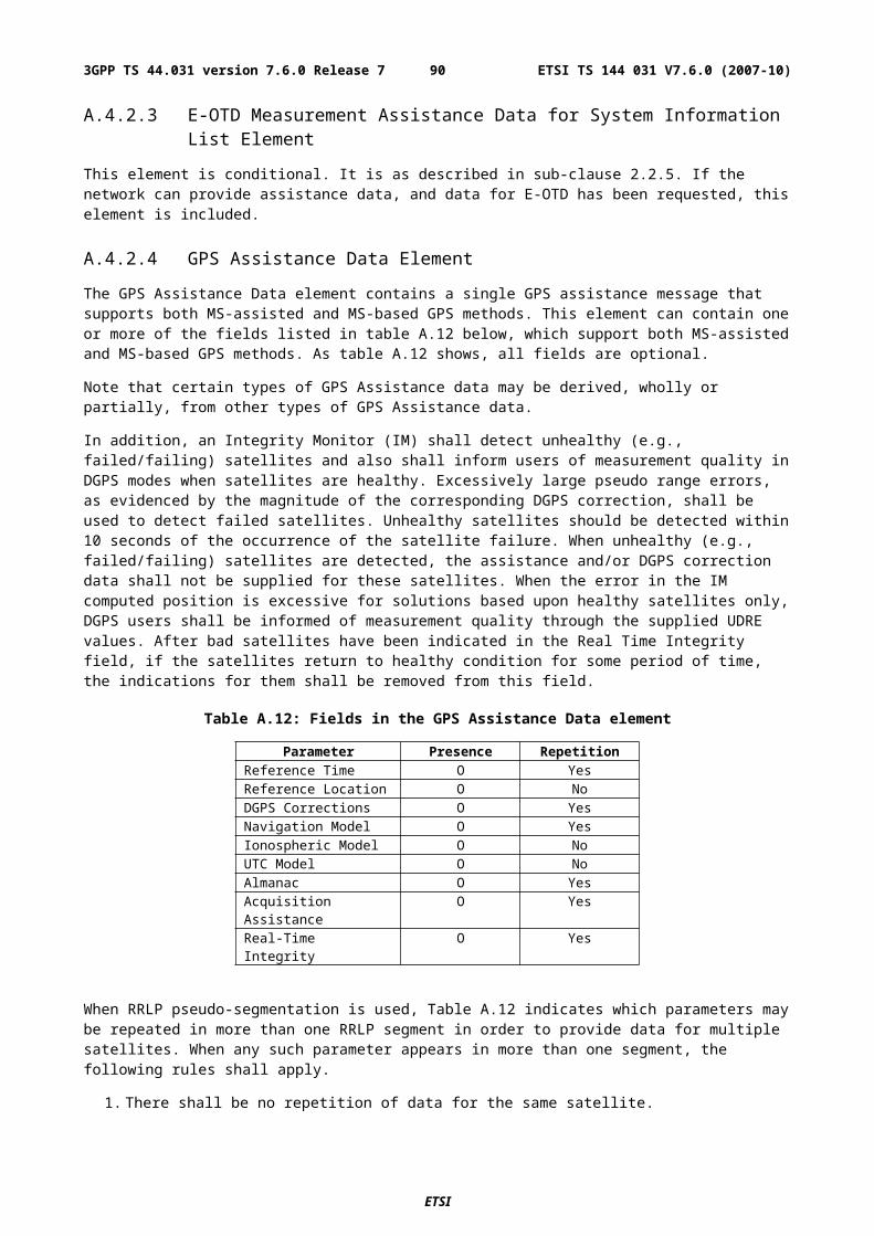
The value "110" indicates that the source of the differential corrections (e.g., reference station or external DGANSS network) is currently not being monitored. The value "111" indicates that the corrections provided by the source are invalid, as judged by the source. In the later case, the message shall contain no corrections for individual satellites. Any MS that receives DGANSS Corrections in a GANSS Assistance Data IE shall contain the appropriate logic to properly interpret this condition and look for the next IE.
N_SGN
This field indicates the number of signals per a specified GANSS_Signal_ID for which differential corrections are available. Corrections are possible for up to 16 signals.
SV_ID
The SV ID is an index number for a satellite.
Issue Of Data
Issue of Data field contains the identity for the GANSS Navigation Model.
User Differential Range Error (UDRE)
This field provides an estimate of the uncertainty (1-) in the corrections for the particular satellite. The value in this field shall be multiplied by the UDRE Scale Factor in the common Corrections Status/Health field to determine the final UDRE estimate for the particular satellite. The meanings of the values for this field are described in Table A.45.
Table A.45: Values of UDRE IE
Value Indication00 UDRE £ 1.0 m01 1.0 m < UDRE £ 4.0 m10 4.0 m < UDRE £ 8.0 m11 8.0 m < UDRE
Each UDRE value shall be adjusted based on the operation of an Integrity Monitor (IM) function which exists at the network (SMLC, GPS server, or reference GPS receiver itself). Positioning errors derived at the IM which are excessive relative to DGPS expected accuracy levels shall be used to scale the UDRE values to produce consistency.
Pseudo-Range Correction (PRC)
This field indicates the correction to the pseudorange for the particular satellite at t0. The value of this field is given in meters (m) and the resolution is 0.32, as shown in Table A.41 above. The method of calculating this field is described in [9].
If the SMLC has received a request for GANSS assistance data from an MS which included a request for the navigation models and DGANSS (i.e., bit D and E are set to one in "Requested GANSS Assistance Data, see 3GPP TS 49.031), the SMLC shall determine, for each satellite, if the navigation model stored by the MS is still suitable for use with DGANSS corrections (also see navigation model update conditions right before Table A.46) and if so and if DGANSS corrections are supported the SMLC should send DGANSS corrections without including the navigation model.
The IOD value sent for a satellite shall always be the IOD value that corresponds to the navigation model for which the pseudo-range corrections are applicable.
The pseudo-range correction shall correspond to the available navigation model (the one already stored in and identified by the MS or the one included in the same procedure as the pseudo-range correction). The MS shall only use the PRC value when the IOD value received matches its available navigation model.
Pseudo-Range Rate Correction (RRC)
This field indicates the rate-of-change of the pseudorange correction for the particular satellite, using the satellite ephemeris identified by the IOD IE. The value of this field is given in meters per second (m/sec) and the resolution is 0.032, as shown in table A.43 above. For some time t1 > t0, the corrections for IOD are estimated by
PRC(t1, IOD) = PRC(t0, IOD) + RRC(t0, IOD)(t1 - t0) ,
and the MS uses this to correct the pseudorange it measures at t1, PRm(t1, IOD), by
ETSI
ETSI TS 144 031 V7.6.0 (2007-10)903GPP TS 44.031 version 7.6.0 Release 7
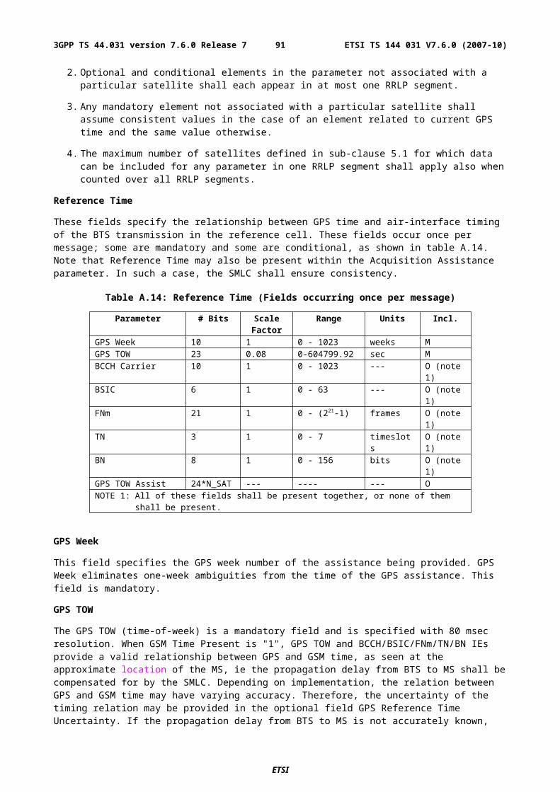
PR(t1, IOD) = PRm(t1, IOD) + PRC(t1, IODE) .
The SMLC shall always send the RRC value that corresponds to the PRC value that it sends (see above for details). The MS shall only use the RRC value when the IOD value received matches its available navigation model.
In order to extend the life-time of DGANSS corrections, SMLC can send an optional 2nd order rate-of-change of the pseudorange correction for the particular satellite using the satellite identified by the IOD IE. The value of this field is given in meters per second2 (m/sec2). In this case, the corrections for IOD are estimated by
PRC(t1, IOD) = PRC(t0, IOD) + RRC(t0, IOD)(t1 - t0) + RRC2(t0, IOD)(t1 - t0)2 ,
and the MS uses this to correct the pseudorange it measures at t1, PRm(t1, IOD), by
PR(t1, IOD) = PRm(t1, IOD) + PRC(t1, IODE) .
GANSS Navigation Model
This set of fields contains information required to manage the transfer of precise navigation data to the GANSS-capable MS. In response to a request from a MS for GANSS Assistance Data, the SMLC shall determine whether to send the navigation model for a particular satellite to an MS based upon factors like the T-Toe limit specified by the MS and any request from the MS for DGANSS (also see above). This information includes control bit fields as well as satellite ephemeris and clock corrections and clock and orbit accuracy models. GANSS Orbit Model can be given in Keplerian parameters.
GANSS Navigation Model element can contain data up to at most 32 satellites. The individual fields are given in Table A.46 and the conditions for their presence is discussed below.
Table A.46: GANSS Navigation Model contents
Parameter # Bits Scale Factor Units Incl.Navigation Model Flow Control (once per message)
Num_Sat 5 1 --- MNon-Broadcast Indication 1 --- --- Mtoe/c_MSB 5 21600 sec Ce_MSB 7 2-8 --- C
sqrtA_MSB 6 27 m1/2 C
The following fields occur once per satellite (Num_Sat times)SV ID 6 --- --- MSV Health 5 --- --- MIOD 10 --- --- MGANSS Clock Model See Table A.49.1 --- --- MGANSS Orbit Model See Table A.49.2 --- --- M
Num_Sat
This field specifies the number of satellites that are included in the provided GANSS Navigation Model element. A range of 1-32 is available. This field is mandatory when the GANSS Navigation Model field is included in the GANSS Assistanace Data message.
Non-Broadcast Indication
This field indicates if the GANSS Navigation Model Elements are not derived from satellite broadcast data or are given in a format not native to the GANSS.
Table A.47: Values of Non-Broadcast Indication Flag
Value Non-Broadcast Indication0 GANSS Navigation Data elements corresponding with broadcasted
data1 GANSS Navigation Data element not derived from satellite broadcast
toe/c_MSB
ETSI
ETSI TS 144 031 V7.6.0 (2007-10)913GPP TS 44.031 version 7.6.0 Release 7
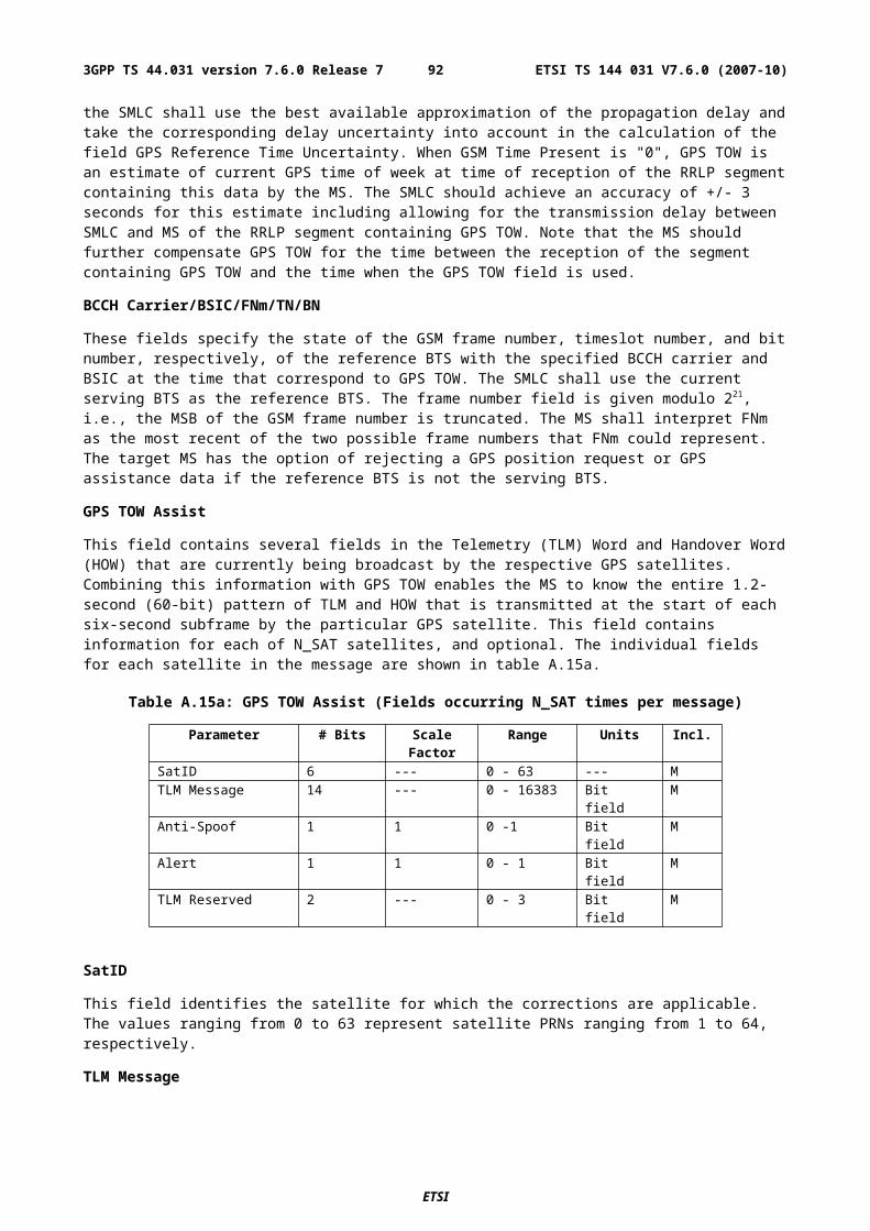
This field specifies the 12MSB of toe and toc.
The MS calculates e.g. toe [s] for the Satellite Navigation Model Using Keplerian Parameters by combining the field toe/c_MSB with toe_LSB in the following way
toe = toe/c_MSB*21600 + toe_LSB*60
toe and toc parameters are given in GNSS specific system times i.e. no conversions are needed on the combined toe or toc.
e_MSB
This field specifies the 12MSB of eccentricity parameter of the Keplerian GANSS Orbit Model.
The MS calculates eccentricity parameter for the Satellite Navigation Model Using Keplerian Parameters by combining the field e_MSB with e_LSB in the following way
e = e_MSB*2-8 + e_LSB*2-33
sqrtA_MSB
This field specifies the 12MSB of square root of semi-major axis parameter of the Keplerian GANSS Orbit Model.
The MS calculates square root of the semi-major axis parameter for the Satellite Navigation Model Using Keplerian Parameters by combining the field sqrtA_MSB with sqrtA_LSB in the following way
sqrtA = sqrtA _MSB*27 + sqrtA _LSB*2-19
SV_ID
The field specifies the SV/Slot ID for which the GANSS Navigation Model Elements is given.
Range: 0 - 63
SV Health
This parameter gives information about the satellite"s current health. The health values are GNSS system specific. In the case of Galileo, the SV Health bits have the encoding as in Table A.48.1.
Table A.48.1: Galileo SV Health Bits [11, pages 75-76]
Parameter # Bits Scale Factor
Range Units
E5a Data Validity Status 1 --- 0 - 1 Bit fieldE5b Data Validity Status 1 --- 0 - 1 Bit fieldE1-B Data Validity Status 1 --- 0 - 1 Bit fieldE5a Signal Health Status 2 --- See [11], Table 67 Bit field
Issue Of Data
Issue of Data field contains the identity for GANSS Navigation Model. In the case of broadcasted Galileo ephemeris, the IOD contains the IOD index as described in [11].
GANSS Clock Model
GANSS clock model contains one or two clock model elements depending on the GNSS. Clock model shall be included once or twice depending on the MS capability.
If the MS is supporting multiple Galileo signals, SMLC shall include both F/Nav and I/Nav clock models in GANSS Clock Model IE if the SMLC assumes the MS to perform Location Information calculation using multiple signals. The MS capabilities to support multiple GNSS frequencies are indicated in the MS Classmark 3. Otherwise, SMLC shall include only the model suitable for the GNSS.
ETSI
ETSI TS 144 031 V7.6.0 (2007-10)923GPP TS 44.031 version 7.6.0 Release 7
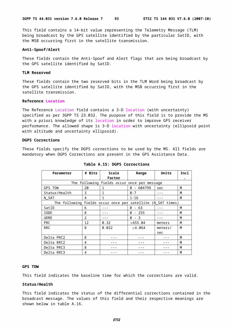
Table A.49.1: GANSS Clock Model
Parameter # Bits Scale Factor Units Incl.Standard Satellite Clock Model (can occur multiple times per model, N_CLOCK, if selected)
toc_LSB 9(u) 60 sec C(1)
af2 12 2-65, if GANSS_ID indicates Galileo
sec/sec2 C(1)
af1 18 2-45 sec/sec C(1)
af0 28 2-33 sec C(1)
TGD 10 2-32, if GANSS_ID indicates Galileo
sec O(1)
Model ID 1 --- --- O
Model ID
This field specifies the identity of the clock model according to Table A.49.1a. This field is optional.
Table A.49.1a: Galileo Clock Model Identity
Value Identity0 I/Nav1 F/Nav
toc_LSB
This field specifies the LSB of Time of Clock in different models.
GANSS Orbit Model
GANSS Orbit Model IE contains the following presentation: Satellite Navigation Model Using Keplerian Parameters as described in Table A.49.2.
Table A.49.2: GANSS Orbit Model
Parameter # Bits Scale Factor Units Incl.Satellite Navigation Model Using Keplerian Parameters
toe_LSB 9(u) 60 sec C 32 2-31 semi-circles Cn 16 2-43 semi-circles/sec CM0 32 2-31 semi-circles COMEGAdot 24 2-43 semi-circles/sec Ce_LSB 25(u) 2-33 --- CIdot 14 2-43 semi-circles/sec CsqrtA_LSB 26(u) 2-19 meters1/2 Ci0 32 2-31 semi-circles COMEGA0 32 2-31 semi-circles CCrs 16 2-5 meters CCis 16 2-29 radians CCus 16 2-29 radians CCrc 16 2-5 meters CCic 16 2-29 radians CCuc 16 2-29 radians CNOTE u: unsigned parameter
toe_LSB
This field specifies the LSB of Time of Ephemeris.
e_LSB
This field specifies the LSB of the eccentricity parameter.
ETSI
ETSI TS 144 031 V7.6.0 (2007-10)933GPP TS 44.031 version 7.6.0 Release 7
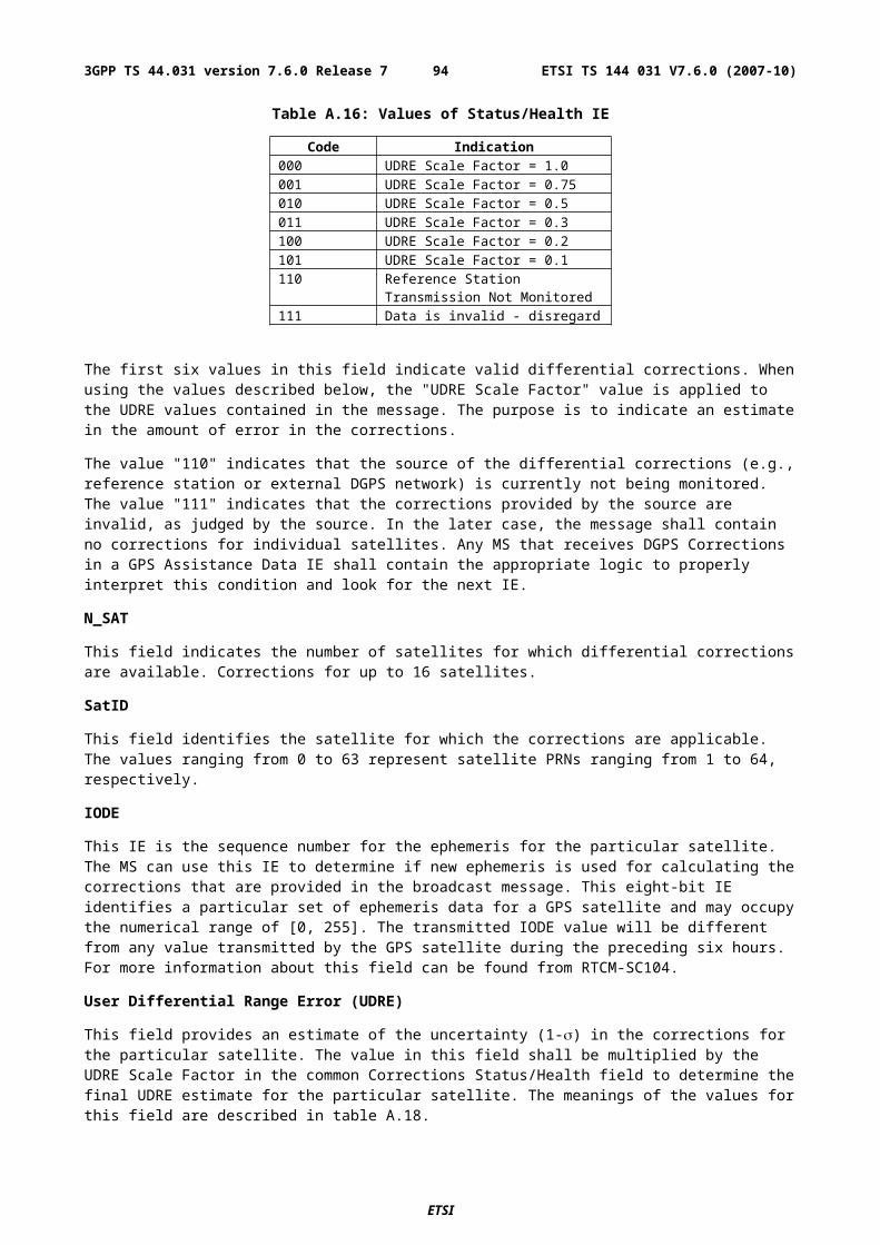
sqrtA_LSB
This field specifies the LSB of the square root of semi-major axis parameter.
GANSS Real-Time Integrity
Integrity Monitor (IM) shall detect unhealthy (e.g., failed/failing) satellite signals and also shall inform users of measurement quality in DGANSS modes when satellite signals are healthy. Excessively large pseudo range errors, as evidenced by the magnitude of the corresponding DGANSS correction, shall be used to detect failed satellite signals. Unhealthy satellite signals should be detected within 10 seconds of the occurrence of the satellite signal failure. When unhealthy (e.g., failed/failing) satellite signals are detected, the assistance and/or DGANSS correction data shall not be supplied for these satellite signals. When the error in the IM computed position is excessive for solutions based upon healthy satellite signals only, DGANSS users shall be informed of measurement quality through the supplied UDRE values. After bad satellite signals have been indicated in the Real Time Integrity field, if the satellite signals return to healthy condition for some period of time, the indications for them shall be removed from this field.
GANSS Real-Time Integrity field of the GANSS Assistance Data Information Element contains parameters that describe the real-time status of the GANSS constellations. Primarily intended for non-differential applications, the real-time integrity of the satellite constellation is of importance as there is no differential correction data by which the mobile can determine the soundness of each satellite signal. GANSS Real-Time Integrity data communicates the health of the GNSS signals to the mobile in real-time. The format is shown in Table A.50. The SMLC shall always transmit the GANSS Real Time Integrity field with the current list of unhealthy signals, for any GANSS positioning attempt and whenever GANSS Assistance Data is sent. If the number of bad signals (NBS) is zero, then the GANSS Real Time Integrity field shall be omitted.
Table A.50: GANSS Real-Time Integrity
Parameter # Bits Scale Factor Range Units Incl.The following fields occur once per SV with bad signal (NBS times)
Bad_GNSS_SV_ID 6 1 --- --- MBad_GNSS_Signal_ID 8 1 --- --- O
NBS (Number of satellites with bad signal)
The NBS value indicates the number of satellites with bad signal.
Bad_GNSS_SV_ID
This field specifies the SV ID of the satellite with bad signal or signals.
Bad_GNSS_Signal_ID
This field identifies the bad signal of a satellite. Absence of this field means that all signals on the specific SV are bad. The Bad_GNSS_Signal_ID for Galileo are listed in Table A.59.
GANSS Data Bit Assistance
This element provides data bit assistance data for specific satellite signals for data wipe-off. The data bits included in the assistance data depends on the GANSS and its signal.
Table A.51: GANSS Data Bit Assistance
Parameter Bits Resolution Range Incl.GANSS TOD 6 1 0 – 59 M
The following fields occur once per satellite (N_SAT times)SV ID 6 1 --- M
The following fields occur once per signal (N_SGN times)GANSS_Signals See Table
A.59--- --- M
N_BIT 10 1 1 – 1024 MData Bits N_BIT --- --- M
GANSS TOD
ETSI
ETSI TS 144 031 V7.6.0 (2007-10)943GPP TS 44.031 version 7.6.0 Release 7
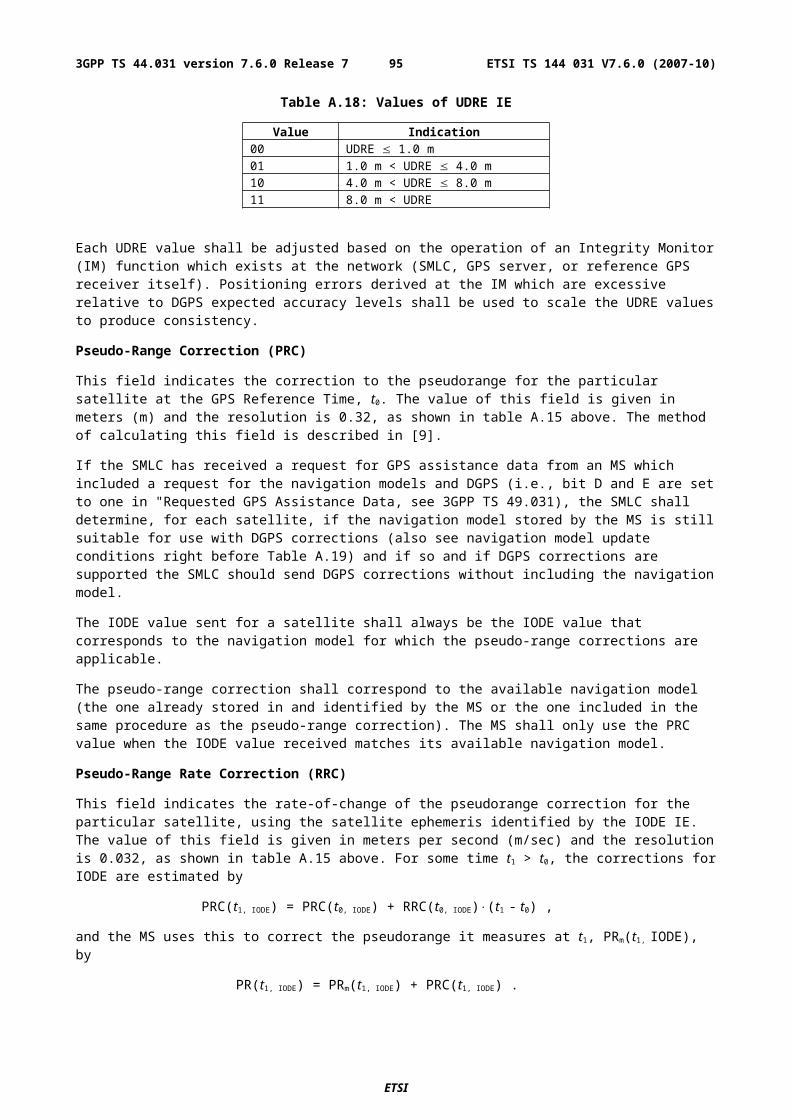
This field indicates the reference time of the first bit of the data in GANSS Data Bit Assistance in integer seconds in GNSS specific system time.
Data Bit Reference Time is given as modulo 60 s from GANSS TOD.
N_SAT
This field specifies the number of satellites in GANSS Data Bit Assistance element.
SV_ID
The field specifies the SV for which the GANSS Data Bit Assistance is given.
Range: 0 – 63
N_SGN
This field specifies the number of signals for which GANSS Data Bit Assistance is provided.
Range: 1 – 8
GANSS_Signals
This field specifies the GANSS signal type of the GANSS Data Bit Assistance as listed in Table A.59.
N_BIT
This field indicates the number of bits (or symbols) included in the IE.
Data Bits
Data bits are contained in GNSS system and data type specific format.
GANSS Reference Measurement Information
This field provides reference code and Doppler measurement information of visible satellites of a GANSS constellation. The information can be used as acquisition assistance to improve the sensitivity of the receiver.
These parameters describe the range and optionally the derivatives from respective satellites to the GANSS Reference Location at the GANSS Reference Time. The code phase and Doppler fields are aligned with the time provided in GANSS Reference Time. Figure A.4a illustrates the relation between some of the fields with respect to the GANSS TOD.
If GPS Acquisition Assistance is included the Reference Time included in the GPS Acquisition Assistance is also valid for the GANSS Reference Measurement fields and the parameters are referenced to GPS TOW. Figure A.4b illustrates the relation between some of the fields with respect to GPS TOW.
The parameters are given in units of ms and m/s which makes it possible to convert the values to any nominal frequency and chipping and code rate.
ETSI
ETSI TS 144 031 V7.6.0 (2007-10)953GPP TS 44.031 version 7.6.0 Release 7
Table A.52: GANSS Reference Measurement Information Contents
Parameter Range Bits Resolution Incl.GANSS_Signal_ID 0 - 3 2 --- O
The following fields occur once per satellite (Num_Sat times)SV_ID 0 - 63 6 MDoppler (0th order term) -1024 m/s to 1023.5 m/s 12 0.5 m/s MDoppler (1st order term) -0.2 - 0.1 m/s2. 6 1/210 m/s2. O(1)
Doppler Uncertainty 2.5 m/s - 40 m/s [2-n(40) m/s, n = 0 - 4]
3 --- O(1)
Code Phase 0 - (1-2-10) ms 10 2-10 ms MInteger Code Phase 0 - 127 ms 7 1 ms MCode Phase Search Window
See Table A.53 5 --- M
Azimuth 0 - 348.75 deg 5 11.25 deg O(2)
Elevation 0 - 78.75 deg 3 11.25 deg O(2)
NOTE 1,2:All of these fields shall be present together, or none of them shall be present.
Figure A.4a. Exemplary calculations of some GANSS Reference Measurement fields with respect to GANSS TOD.
ETSI
ETSI TS 144 031 V7.6.0 (2007-10)963GPP TS 44.031 version 7.6.0 Release 7
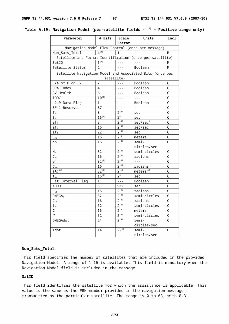
Figure A.4b. Exemplary calculations of some GANSS Reference Measurement fields with respect to GPS TOW.
GANSS_Signal_ID
This field specifies the GNSS signal type. Absence of GANSS_Signal_ID indicates Galileo L1 OS signal in Galileo case. The supported signals for Galileo are listed in Table A.43.1.
Num_Sat
This field specifies the number of satellites in GANSS Reference Measurement Information element.
Doppler (0th order term)
This field contains the Doppler (0th order term) value. A positive value in Doppler defines the increase in satellite signal frequency due to velocity towards the MS. A negative value in Doppler defines the decrease in satellite signal frequency due to velocity away from the MS.
Doppler is given in unit of m/s by multiplying the Doppler value in Hz by the nominal wavelength of the assisted signal.
This field is mandatory.
Doppler (1st order term)
This field contains the Doppler (1st order term) value. A positive value defines the rate of increase in satellite signal frequency due to acceleration towards the MS. A negative value defines the rate of decrease in satellite signal frequency due to acceleration away from the MS.
ETSI
ETSI TS 144 031 V7.6.0 (2007-10)973GPP TS 44.031 version 7.6.0 Release 7
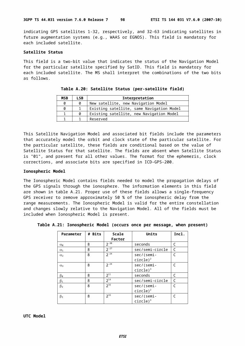
Doppler (1st order term) is given in unit of m/s by multiplying the Doppler value in Hz by the nominal wavelength of the assisted signal.
This field is optional.
Doppler Uncertainty
This field contains the Doppler uncertainty value. It is defined such that the Doppler experienced by a stationary MS is in the range "Doppler Doppler Uncertainty" to "Doppler Doppler Uncertainty". This field is optional. If Doppler Uncertainty (together with Doppler 1st order term) is omitted, the terminal shall interpret Doppler Uncertainty as greater than +/-40 m/s.
Doppler Uncertainty is given in unit of m/s by multiplying the Doppler Uncertainty value in Hz by the nominal wavelength of the assisted signal.
Permitted Values: 2.5 m/s, 5 m/s, 10 m/s, 20 m/s, 40 m/s as encoded by an integer n in the range 0-4 according to the formula in Table A.52.
Code Phase
This field contains code phase, in units of milliseconds, in the range from 0 to 1 millisecond scaled by the nominal chipping rate of the GNSS signal, where increasing values of the field signify increasing predicted signal code phases, as seen by a receiver at the Reference Location at the GANSS Reference Time. The Reference Location would typically be an apriori estimate of the MS location. This field is mandatory.
Range. 0 - (1-2-10) ms
Integer Code Phase
This field contains integer code phase (expressed modulo 128 ms) currently being transmitted at the GANSS Reference Time, as seen by a receiver at the Reference Location. This field is mandatory.
Range: 0-127 ms
Code Phase Search Window
This field contains the code phase search window. The code phase search window accounts for the uncertainty in the estimated MS location but not any uncertainty in GANSS Reference Time. It is defined such that the expected code phase is in the range "Code Phase - Code Phase Search Window" to "Code Phase + Code Phase Search Window" given in units of milliseconds. This field is mandatory.
Range: 0-31 (i.e. 0.002 - 2,000 ms according to following table)
ETSI
ETSI TS 144 031 V7.6.0 (2007-10)983GPP TS 44.031 version 7.6.0 Release 7
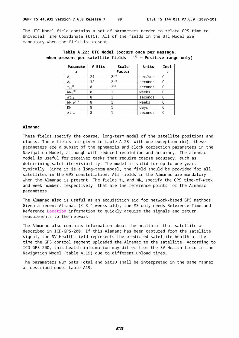
Table A.53: Code Phase Search Window Parameter Format
CODE_PHASE_SEARCH_WINDOW Code Phase Search Window [ms]'00000' No information'00001' 0,002'00010' 0,004'00011' 0,008'00100' 0,012'00101' 0,016'00110' 0,024'00111' 0,032'01000' 0,048'01001' 0,064'01010' 0,096'01011' 0,128'01100' 0,164'01101' 0,200'01110' 0,250'01111' 0,300'10000' 0,360'10001' 0,420'10010' 0,480'10011' 0,540'10100' 0,600'10101' 0,660'10110' 0,720'10111' 0,780'11000' 0,850'11001' 1,000'11010' 1,150'11011' 1,300'11100' 1,450'11101' 1,600'11110' 1,800'11111' 2,000
Azimuth
This field contains the azimuth angle. An angle of x degrees means the satellite azimuth a is in the range (x £ a < x+11.25) degrees. This field is optional.
Range: 0 - 348.75 degrees.
Elevation
This field contains the elevation angle. An angle of y degrees means the satellite elevation e is in the range (y £ e < y+11.25) degrees except for y = 78.75 where the range is extended to include 90 degrees. This field is optional.
Range: 0 - 78.75 degrees
GANSS Almanac Model
ETSI
ETSI TS 144 031 V7.6.0 (2007-10)993GPP TS 44.031 version 7.6.0 Release 7
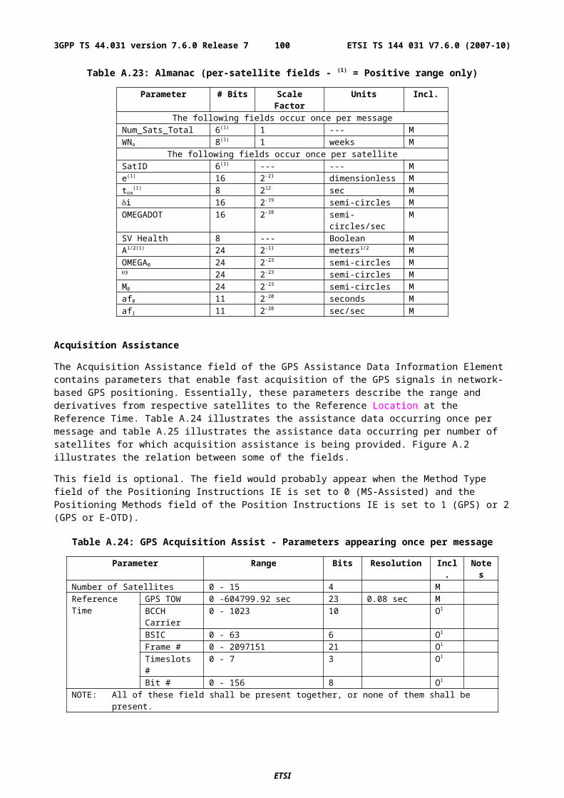
These fields specify the coarse, long-term model of the satellite positions and clocks. These fields are given in Table A.54. GANSS Almanac Model is useful for receiver tasks that require coarse accuracy, such as determining satellite visibility. The model is valid for up to few weeks, typically. Since it is a long-term model, the field should be provided for all satellites in the GNSS constellation.
Table A.54: GANSS Almanac Model (per-satellite fields - (1) = Positive range only)
Parameter # Bits Scale Factor Units Incl.The following fields occur once per message
Num_Sats_Total 6 1 --- MWeek Number 8 1 weeks MSV_ID_Mask 36 1 --- MToa 8 212 s O (note 1)IODa 2 --- --- O (note 1)
This model occurs once per satellite (Num_Sats_Total times)GANSS Almanac Model Using Keplerian Parameters
e 11 2-16 dimensionless M i 11 2-14 semi-circles M OMEGADOT 11 2-33 semi-circles/sec M SV Health_KP 4 --- dimensionless M delta_A1/2 17 2-9 meters1/2 M OMEGA0 16 2-15 semi-circles M 16 2-15 semi-circles M M0 16 2-15 semi-circles M af0 14 2-19 seconds M af1 11 2-38 sec/sec M NOTE 1: All of these field shall be present together, or none of them shall be present.
Num_Sats_Total
This field specifies the total number of satellites in GANSS Almanac Model.
Range: 1 - 36
Week Number
This field specifies the Almanac reference week number in GNSS specific system time to which the Almanac Reference Time Toa is referenced.
Range: 0 - 255
SV_ID_Mask
This field specifies a 36-bit bit field that defines the SV_ID"s of the satellites included in GANSS Almanac Model. The satellite specific almanacs are ordered in GANSS Almanac Model according to the SV_ID_Mask, starting from the smallest SV_ID first, the greatest SV_ID last.
Toa
This field specifies the Almanac Reference Time common to all satellites in GANSS Almanac Model Using Keplerian Parameters given in GNSS specific system time.
IODa
This field specifies the Issue-Of-Data common to all satellites in GANSS Almanac Model Using Keplerian Parameters.
SV Health_KP
This field specifies the SV Health status in GANSS Almanac Model Using Keplerian Parameters. In Galileo case this field shall contain the I/NAV health status bits.
GANSS UTC Model
The GANSS UTC Model field contains a set of parameters needed to relate GNSS system time to Universal Time Coordinate (UTC). All of the fields in the GANSS UTC Model are mandatory when the field is present.
ETSI
ETSI TS 144 031 V7.6.0 (2007-10)1003GPP TS 44.031 version 7.6.0 Release 7
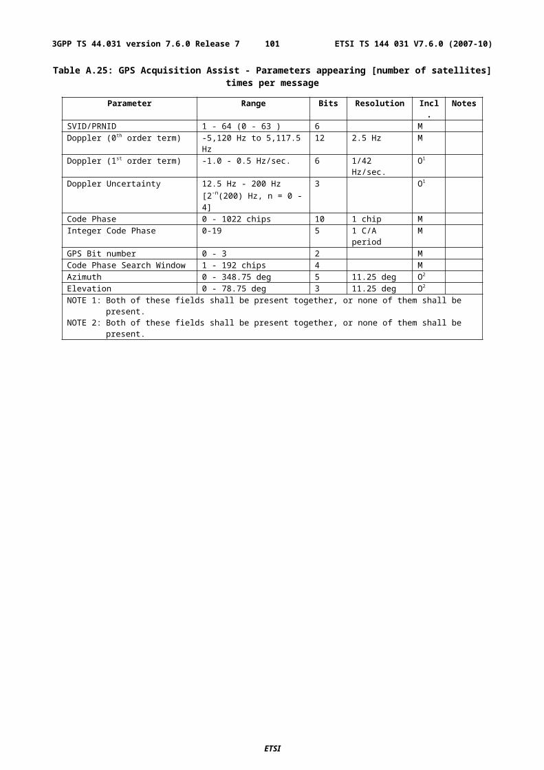
Table A.55: GANSS UTC Model
Parameter # Bits Scale Factor Units Incl.A1 24 2-50 sec/sec CA0 32 2-30 seconds Ctot 8 212 seconds CWNt 8 1 weeks CtLS 8 1 seconds CWNLSF 8 1 weeks CDN 8 1 days CtLSF 8 1 seconds C
A.4.2.7 GANSS Carrier-Phase Measurement Request Element
This element is optional and controls if the MS should return carrier-phase measurements in GANSS Measurement Information IE or not to the SMLC. The inclusion of this parameter implies use of measure Position Request. The description is found in sub-chapter 2.2.4d.
A.4.2.8 GANSS TOD - GSM Time Association Request Element
This element is optional and controls if the MS should return GANSS TOD - GSM Time Association Measurements or not to the SMLC. The inclusion of this parameter implies use of measure Position Request. The description is found in sub-chapter 2.2.4e.
A.5 Assistance Data Acknowledgement
A.5.1 GeneralThe MS sends the Assistance Data Acknowledgement component to the SMLC to indicate that it has received the whole Assistance Data component.
A.6 Protocol Error
A.6.1 GeneralThis component is used by the receiving entity (SMLC or MS) to indicate to the sending entity, that there is a problem that prevents the receiving entity to receive a complete and understandable component.
This component has the following values:
'0': Undefined;'1': Missing Component;'2': Incorrect Data;'3': Missing Information Element or Component Element;'4': Message Too Short;'5': Unknown Reference Number.
A.6.2 Extended Reference IEThis IE shall be included in any Protocol Error message if and only if an Extended Reference IE was received in the corresponding previous Measure Position Request or Assistance Data message.
NOTE: For reasons of backward compatibility, a Release 4 or earlier MS will not include this IE.
The Extended Reference IE contains the following elements.
ETSI
ETSI TS 144 031 V7.6.0 (2007-10)1013GPP TS 44.031 version 7.6.0 Release 7
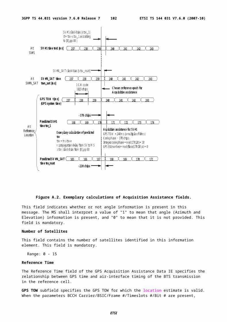
SMLC code: an integer in the range 0-63. The value returned by a target MS in a Protocol Error message shall equal the value received from the SMLC in the earlier Measure Position Request or Assistance Data message.
Transaction ID: an integer in the range 0-262143 distinguishing different RRLP transactions in different MSs currently being served by the same SMLC. The value returned by a target MS in a Protocol Error message shall equal the value received from the SMLC in the earlier Measure Position Request or Assistance Data message.
A.7 Positioning Capability Request
A.7.1 GeneralThe SMLC sends the Positioning Capability Request component to the MS to request the MS positioning capabilities, types of assistance data supported and any assistance data that may be needed. It contains the following elements.
Table A.56: Positioning Capability Request component content
Element Type/Reference PresenceExtended Reference Extended Reference
2.2.5M
A.8 Positioning Capability Response
A.8.1 GeneralThe Positioning Capability Response is a RRLP component from the MS to the network. It is the response to the Positioning Capability Request. It contains the following elements.
Table A.57: Positioning Capability Response component content
Element Type/Reference PresenceExtended Reference Extended Reference 2.2.5 MPositioning Capabilities Positioning Capabilities 8.2.1 MAssistance Data Supported Assistance Data Supported 8.2.2 OAssistance Data Needed Assistance Data Needed 8.2.3 O
A.8.2 Elements
A.8.2.1 Positioning Capabilities
This element indicates the positioning methods and other positioning capabilities supported by the MS. The inclusion of this element is mandatory.
The MS may indicate support for non-GANSS position methods and/or GANSS position methods. The MS indicates its support for non-GANSS position methods using a bit string with one bit representing each method, set to one if the method is supported and zero if it is not. The following Non-GANSS Position Methods can be identified:
- MS Assisted E-OTD;
- MS Based E-OTD;
- MS Assisted GPS;
- MS Based GPS;
- Standalone GPS.
ETSI
ETSI TS 144 031 V7.6.0 (2007-10)1023GPP TS 44.031 version 7.6.0 Release 7
The MS indicates its support for GANSS position methods by providing the parameters shown in Table A.58 for each GANSS system supported.
Table A.58: GANSS Position Method Support
GANSS Position Method ParametersGANSS_IDGANSS Position Method TypesGANSS Signals
GANSS_ID
Range: 0 - 7
This field indicates the GANSS. The supported GANSS are defined in sub-clause A.4.2.6.2. Absence of this field indicates Galileo.
GANSS Position Method Types
For each supported GANSS system, the MS shall indicate which method types are supported. This is represented using a bit string with one bit per method type where a one value indicates support and a zero value no support. The following GANSS Method Types can be identified:
- MS Assisted;
- MS Based;
- Standalone.
GANSS Signals
For each supported GANSS system, the MS shall indicate which signals are supported. This is represented using a bit string with one bit per signal where a one value indicates support and a zero value no support. The individual signals are denoted generically as signal1, signal2 etc. in the ASN.1 in clause 5.l. Table A.59 shows the signal correspondence for each defined GANSS system. Unfilled table entries indicate no assignment and shall either not be included or set to zero if included.
Table A.59: GANSS Signal Correspondence
GANSS System Signal 1 Signal 2 Signal 3 Signal 4 Signal 5 Signal 6 Signal 7 Signal 8Galileo E1 E5a E5b E6 E5a+E5b
The MS shall also indicate whether it supports multiple measurement sets for the MS Assisted position methods listed below. This is represented using a bit string with one bit representing each position method which is set to a one if multiple measurement sets are supported for that method and to a zero if not. The following MS Assisted Position Methods associated with Multiple Measurement Sets can be identified:
- E-OTD;
- GPS;
- GANSS.
A.8.2.2 Assistance Data Supported
This element indicates the types of assistance data that the MS supports for GPS and GANSS. In the case of GPS, support for each of the following types of assistance data can be individually indicated using a bit string in which a one value indicates support and a zero no support. The following GPS Assistance Indications can be identified:
- Almanac;
- UTC model;
ETSI
ETSI TS 144 031 V7.6.0 (2007-10)1033GPP TS 44.031 version 7.6.0 Release 7
- Ionospheric Model;
- Navigation Model;
- DGPS Corrections;
- Reference Location;
- Reference Time;
- Acquisition Assistance;
- Real Time Integrity.
In the case of GANSS, support for each of the following types of common assistance data is indicated using a bit string in which each bit represents one type of assistance data and is set to a one to indicate support and a zero to indicate no support. The following Common GANSS Assistance Indications can be identified:
- GANSS Reference Time;
- GANSS Reference Location;
- GANSS Ionospheric Model.
The MS indicates its support for assistance data specific to each GANSS system by providing the parameters shown in Table A.60 for each GANSS system supported.
Table A.60: GANSS Assistance Support
GANSS Assistance ParametersGANSS_IDGANSS Assistance
GANSS_ID
Range: 0 - 7
This field indicates the GANSS. The supported GANSS are defined in sub-clause A.4.2.6.2. Absence of this field indicates Galileo.
GANSS Assistance
Supported GANSS Assistance data is indicated using a bit string in which each bit represents one type of assistance data and is set to a one to indicate support and a zero to indicate no support. The following types of Specific GANSS Assistance Indications can be identified.
- GANSS Real Time Integrity;
- GANSS Differential Corrections;
- GANSS Almanac;
- GANSS Reference Measurement Information;
- GANSS Navigation Model;
- GANSS Time Model GNSS-UTC;
- GANSS Time Model GNSS-GNSS;
- GANSS Data Bit Assistance.
ETSI
ETSI TS 144 031 V7.6.0 (2007-10)1043GPP TS 44.031 version 7.6.0 Release 7
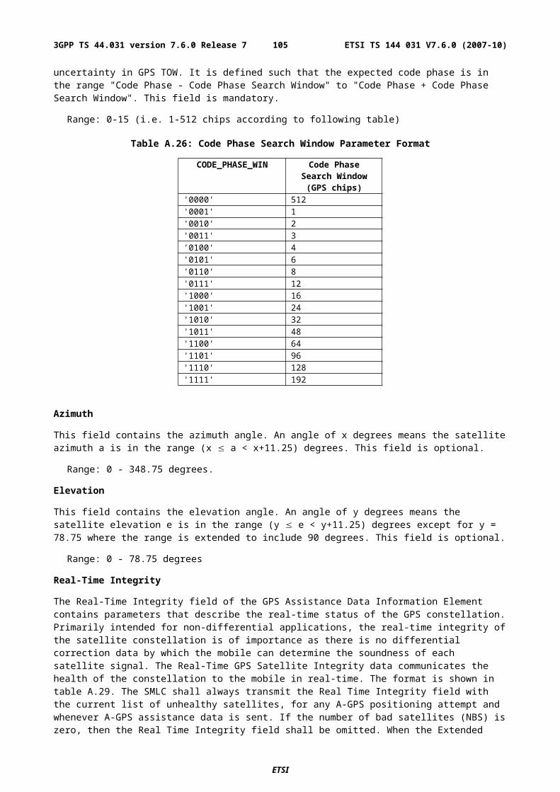
A.8.2.3 Assistance Data Needed
This element indicates the types of assistance data that the MS may need to obtain a location estimate or positioning measurements. The MS shall use this IE to indicate to the SMLC all the supported assistance data types for which the MS does not have current versions using the assistance data request IEs defined in 3GPP TS 49.031. The SMLC can then decide which subset of these assistance data types if any to download. The IE is encoded using the request for assistance data IEs defined for GPS and GANSS in 3GPP TS 49.031.
ETSI
ETSI TS 144 031 V7.6.0 (2007-10)1053GPP TS 44.031 version 7.6.0 Release 7
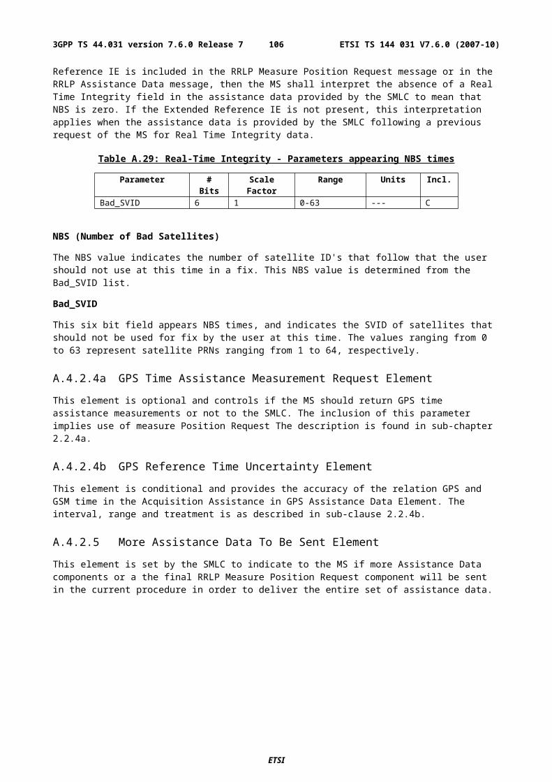
Annex B (informative):Change History
ETSI
ETSI TS 144 031 V7.6.0 (2007-10)1063GPP TS 44.031 version 7.6.0 Release 7
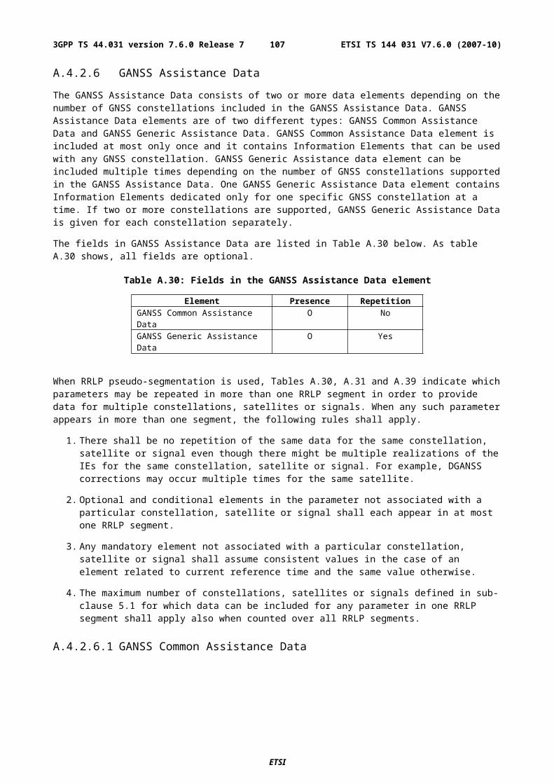
Meeting# Tdoc CR Rev Subject/Comment New Version
GP-06 GP-011880 008 1 Rel-5 version based on 4.2.0.Introduction of LCS for GPRS to RRLP (Rel-5)
5.0.0
GP-07 GP-012170 024 Editorial Corrections 5.1.0GP-07 GP-012309 028 "Expected" Multiframe Offset 5.1.0GP-07 GP-011983 014 1 Corrections to Rough RTD, Multiframe Offset and Expected OTD
ranges.5.1.0
GP-07 GP-012031 018 Correction to Toc and Toe ephemeris parameters 5.1.0GP-07 GP-012029 016 Addition of extension field to assistance data component and some
ASN.1 corrections.5.1.0
GP-07 GP-012220 026 RRLP - Remove references to NSS based SMLC 5.1.0GP-07 GP-012032 019 RRLP - Incomplete interpretation of Assistance Data 5.1.0GP-07 GP-012847 030 2 Correction of Reference Frame in Location Information Element 5.1.0GP-07 GP-012033 022 RRLP - Correction of Error Handling Procedures 5.1.0GP-07 - - Missing table headings included 5.1.0GP-08 GP-020071 031 1 TOM Protocol Header Definition for LCS for GPRS 5.2.0GP-08 GP-020434 033 3 Addition of an extended Reference ID to LCS RRLP Messages 5.2.0GP-08 GP-020490 047 4 Correction to OTD Measurement Response 5.2.0GP-09 GP-020547 057 Usage of "SystemInfoIndex" by the MS in E-OTD measurement
reporting5.3.0
GP-09 GP-020677 052 Removing condition to Control Header parameter 5.3.0GP-09 GP-020709 035 3 Clarification and Correction of DGPS Data Fields 5.3.0GP-09 GP-021224 032 3 Final Response Indication in RRLP for Uplink Pseudo-segmentation 5.3.0GP-09 GP-021266 055 2 Correction of syntax faults in the ASN.1 5.3.0GP-10 GP-021351 062 ASN.1 Faults in GPS Assistance Data 5.4.0GP-10 GP-021355 064 ASN.1 Faults in GPS Measurement Parameters 5.4.0GP-10 GP-021708 060 Correction to Extended Reference IE sub-clause 5.4.0GP-10 GP-021917 066 1 Clean up of downlink segmentation concept 5.4.0GP-10 GP-022107 055 6 Correction of syntax faults in the ASN.1 5.4.0GP-11 GP-022600 068 1 Correction of Pseudo Range Correction range 5.5.0GP-11 GP-022647 069 1 Corrections to GPS Assistance Data Element 5.5.0GP-15 GP-031160 072 1 Correction of the definition of the Real Time Integrity Field for A-GPS 6.0.0GP-16 GP-032272 075 3 Correction of RRLP Pseudo-Segmentation Description 6.1.0GP-18 GP-040424 083 1 Definition of code and Doppler search windows for MS assisted A-GPS 6.2.0GP-18 GP-040434 089 1 Clarification to signalling for conventional GPS location method 6.2.0GP-19 GP-040842 086 2 Definition of code and Doppler search windows for MS assisted A-GPS 6.3.0GP-19 GP-040821 094 Correction to encoding of A-GPS Doppler Uncertainty 6.3.0GP-19 GP-040822 095 Correction and Clarification of A-GPS Doppler Uncertainty 6.3.0GP-20 GP-041673 100 4 Clarification of GPSTOW in Reference Time 6.4.0GP-20 GP-041294 103 3 Correction of inconsistencies between RRLP and MAP specification 6.4.0GP-20 GP-041297 106 Correction of A-GPS Doppler0, Doppler1, Azimuth, Elevation 6.4.0GP-21 GP-042126 117 1 Define rules for pseudo-segmentation of A-GPS Assistance Data 6.5.0GP-22 GP-042578 120 3 Correction of relation between GSM Reference Frame and GPS TOW
to achieve high-accuracy timing assistance for AGPS6.6.0
GP-22 GP-042691 123 4 Correction of the Real-Time Integrity field 6.6.0GP-22 GP-042321 127 1 Correction of allowed RRLP GPS reference location shapes for
compatibility and consistent operation6.6.0
GP-23 GP-050414 131 1 Correction of the ASN.1 code 6.7.0GP-23 GP-050372 132 Corrections to units in Navigation Model 6.7.0GP-24 GP-051159 134 4 Enabling the Providing of Velocity 7.0.0GP-25 GP-051532 0138 1 Specification of MS Assisted A-GPS assistance data use when
Reference Location uncertainty is large7.1.0
GP-27 GP-052490 0142 Correction to the velocity request encoding 7.2.0GP-27 GP-052491 0143 Fractional Chips definition contradiction 7.2.0GP-32 GP-062407 0145 4 A-GNSS support to RRLP 7.3.0GP-33 GP-070123 0148 Addition of Mandatory Response Time element in Measure Position
Request7.4.0
GP-34 GP-070963 0152 Correction to GANSS Reference Time 7.5.0GP-34 GP-070962 0154 1 Correction to GANSS Reference Measurement Assistance 7.5.0GP-34 GP-070979 0162 1 Addition of Positioning Capability Transfer in RRLP 7.5.0GP-34 GP-070983 0163 1 Time ambiguity on GANSS resolution on GANSS measurements 7.5.0GP-34 GP-070839 0164 Clarification for RRLP pseudo-segmentation 7.5.0GP-34 GP-070844 0168 Correction to GPS Time Assistance Measurements IE 7.5.0
ETSI
ETSI TS 144 031 V7.6.0 (2007-10)1073GPP TS 44.031 version 7.6.0 Release 7
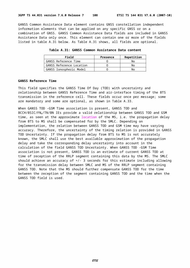
Meeting# Tdoc CR Rev Subject/Comment New Version
GP-35 GP-071299 0173 Correction to GANSS Data Bit Assistance 7.6.0GP-35 GP-071369 0169 1 Additional Description of GPSTOW 7.6.0GP-35 GP-071366 0172 1 Correction to 44.031 Bad Signal Identifier 7.6.0
ETSI
ETSI TS 144 031 V7.6.0 (2007-10)1083GPP TS 44.031 version 7.6.0 Release 7
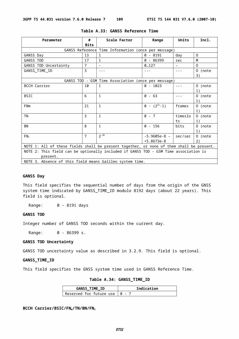
HistoryDocument history
V7.5.0 June 2007 Publication
V7.6.0 October 2007 Publication
ETSI
ETSI TS 144 031 V7.6.0 (2007-10)1093GPP TS 44.031 version 7.6.0 Release 7


![UserPlane Location Protocol - Open Mobile · PDF file[3GPP RRLP] 3GPP TS 44.031, “Location Services (LCS); Mobile Station (MS) – Serving Mobile Location](https://img.pdfslide.net/doc/110x75/5aa2788a7f8b9a80378d0a83/userplane-location-protocol-open-mobile-3gpp-rrlp-3gpp-ts-44031-location.jpg)