Embed Size (px)
Citation preview
3M™ Cold Shrink QT-III Silicone Rubber Termination 7673-S-10(S)-Tape/LCFor Tape Shield or Longitudinally Corrugated (LC) Shielded Cable
InstructionsIEEE Std. No. 48-1996Class 1 Termination69 kV Class, 350 kV BILIEC 6084072,5 kV
F CAUTION Working around energized systems may cause serious injury or death. Installation should
be performed by personnel familiar with good safety practice in handling electrical equipment. De-energize and ground all electrical systems before installing product.
June 201478-8141-7025-0 Rev A 3
2 78-8141-7025-0 Rev A
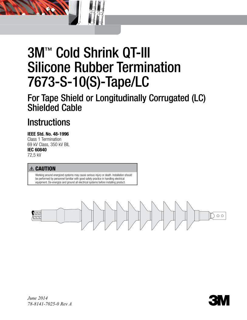
Kit Contents1 Silicone Rubber Lug Seal Insulator Assembly1 Hi-K Stress Control Assembly1 Silicone Rubber Ground Seal Assembly1 Silicone Rubber Skirted Insulator Assembly1 Preformed Ground Braid Assembly3 Constant Force Springs1 Roll Scotch® Electrical Shielding Tape 244 Tubes 3M™ Red Compound P55/R. (Non-Silicone Grease)1 Roll 3M™ Scotch-Seal™ Mastic Tape 2229, 1" (25 mm) wide1 Roll Scotch® Self-fusing Silicone Rubber Electrical Tape 701 Roll Scotch® Vinyl Electrical Tape Super 88, 3/4" × 66'2 Roll Scotch® Rubber Mastic Tape 2228, 2" x 6.5'2 3M™ Cable Cleaning Pads CC-31 3M™ EMI Copper Foil Shielding Tape Strip 1181, 15" long3 Instruction SheetsNote: Utility Colth (Aluminum Oxide) abrasive materials are required for cable preparation, but are NOT INCLUDED IN KIT. Required grits are P180, P240 and P320. Available 3M™ Utility Colth (Aluminum Oxide) Rolls UPC Codes are: P180: 51115-19788 P240: 51115-19786 P320: 51115-19784
Note: Do not use knives to open plastic bags.
Kit Selection Chart
Note: Final determining factor is cable insulation diameter.
Kit Number Primary Insulation O.D. Range
Jacket O.D. Range
Conductor Size Range* AWG (mm2)
7673-S-10(S)2.01"-2.87"
(51,1-72,9 mm)2.25"-3.45"
(57,2-87,6 mm)350-1500 (175-725)
*Based on 650 mil insulation thickness
Table 1
78-8141-7025-0 Rev A 3
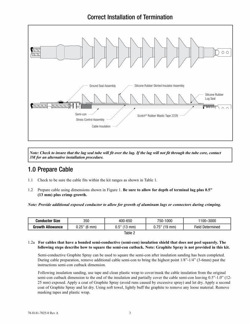
Correct Installation of Termination
Silicone Rubber Skirted Insulator Assembly
Silicone RubberLug Seal
Ground Seal Assembly
Scotch® Rubber Mastic Tape 2228Stress Control Assembly
Cable Insulation
Semi-con
Note: Check to insure that the lug seal tube will fit over the lug. If the lug will not fit through the tube core, contact 3M for an alternative installation procedure.
1.0 Prepare Cable
1.1 Check to be sure the cable fits within the kit ranges as shown in Table 1.
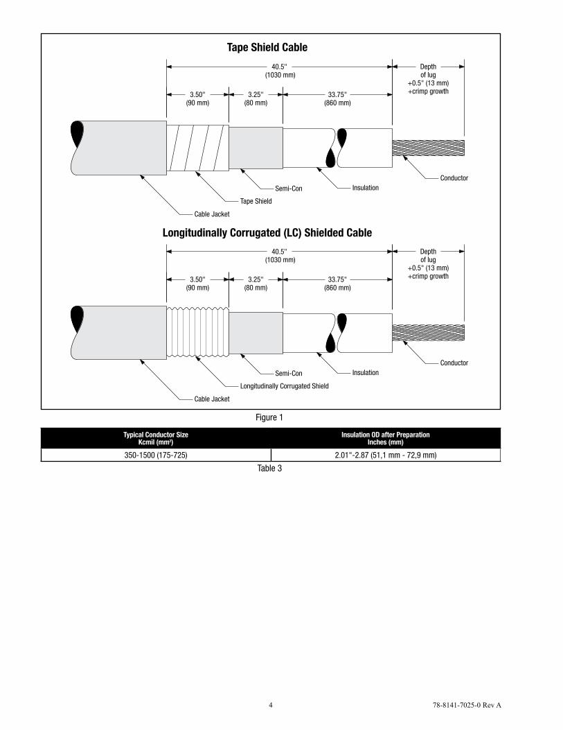
1.2 Prepare cable using dimensions shown in Figure 1. Be sure to allow for depth of terminal lug plus 0.5" (13 mm) plus crimp growth.
Note: Provide additional exposed conductor to allow for growth of aluminum lugs or connectors during crimping.
Conductor Size 350 400-650 750-1000 1100–3000
Growth Allowance 0.25" (6 mm) 0.5" (13 mm) 0.75" (19 mm) Field Determined
Table 2
1.2a For cables that have a bonded semi-conductive (semi-con) insulation shield that does not peel squarely. The following steps describe how to square the semi-con cutback. Note: Graphite Spray is not provided in this kit.
Semi-conductive Graphite Spray can be used to square the semi-con after insulation sanding has been completed. During cable preparation, remove additional cable semi-con to bring the highest point 1/8”-1/4” (3-6mm) past the instructions semi-con cutback dimension.
Following insulation sanding, use tape and clean plastic wrap to cover/mask the cable insulation from the original semi-con cutback dimension to the end of the insulation and partially cover the cable semi-con leaving 0.5”-1.0” (12-25 mm) exposed. Apply a coat of Graphite Spray (avoid runs caused by excessive spray) and let dry. Apply a second coat of Graphite Spray and let dry. Using soft towel, lightly buff the graphite to remove any loose material. Remove masking tapes and plastic wrap.
4 78-8141-7025-0 Rev A
33.75"(860 mm)
40.5" (1030 mm)
Tape Shield
Depthof lug
+0.5" (13 mm)+crimp growth
InsulationConductor
Cable Jacket
Semi-Con
3.25"(80 mm)
3.50"(90 mm)
33.75"(860 mm)
40.5" (1030 mm)
Longitudinally Corrugated Shield
Depthof lug
+0.5" (13 mm)+crimp growth
InsulationConductor
Cable Jacket
Semi-Con
3.25"(80 mm)
3.50"(90 mm)
Tape Shield Cable
Longitudinally Corrugated (LC) Shielded Cable
Figure 1
Typical Conductor SizeKcmil (mm2)
Insulation OD after PreparationInches (mm)
350-1500 (175-725) 2.01"-2.87 (51,1 mm - 72,9 mm)
Table 3
78-8141-7025-0 Rev A 5
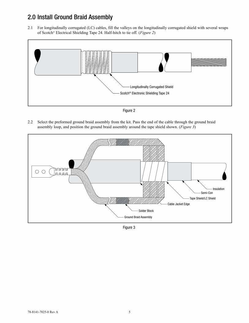
2.0 Install Ground Braid Assembly
2.1 For longitudinally corrugated (LC) cables, fill the valleys on the longitudinally corrugated shield with several wraps of Scotch® Electrical Shielding Tape 24. Half-hitch to tie off. (Figure 2)
Longitudinally Corrugated Shield
Scotch® Electronic Shielding Tape 24
Figure 2
2.2 Select the preformed ground braid assembly from the kit. Pass the end of the cable through the ground braid assembly loop, and position the ground braid assembly around the tape shield shown. (Figure 3)
Tape Shield/LC Shield
Insulation
Cable Jacket Edge
Solder Block
Ground Braid Assembly
Semi-Con
Figure 3
6 78-8141-7025-0 Rev A
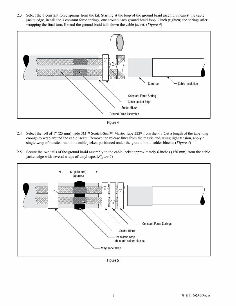
2.3 Select the 3 constant force springs from the kit. Starting at the loop of the ground braid assembly nearest the cable jacket edge, install the 3 constant force springs, one around each ground braid loop. Cinch (tighten) the springs after wrapping the final turn. Extend the ground braid tails down the cable jacket. (Figure 4)
Constant Force Spring
Cable Jacket Edge
Solder Block
Ground Braid Assembly
Cable InsulationSemi-con
Figure 4
2.4 Select the roll of 1" (25 mm) wide 3M™ Scotch-Seal™ Mastic Tape 2229 from the kit. Cut a length of the tape long enough to wrap around the cable jacket. Remove the release liner from the mastic and, using light tension, apply a single wrap of mastic around the cable jacket, positioned under the ground braid solder blocks. (Figure 5)
2.5 Secure the two tails of the ground braid assembly to the cable jacket approximately 6 inches (150 mm) from the cable jacket edge with several wraps of vinyl tape. (Figure 5)
Constant Force Springs
Vinyl Tape Wrap
Solder Block
1st Mastic Strip(beneath solder blocks)
6" (150 mm)(approx.)
Figure 5
78-8141-7025-0 Rev A 7
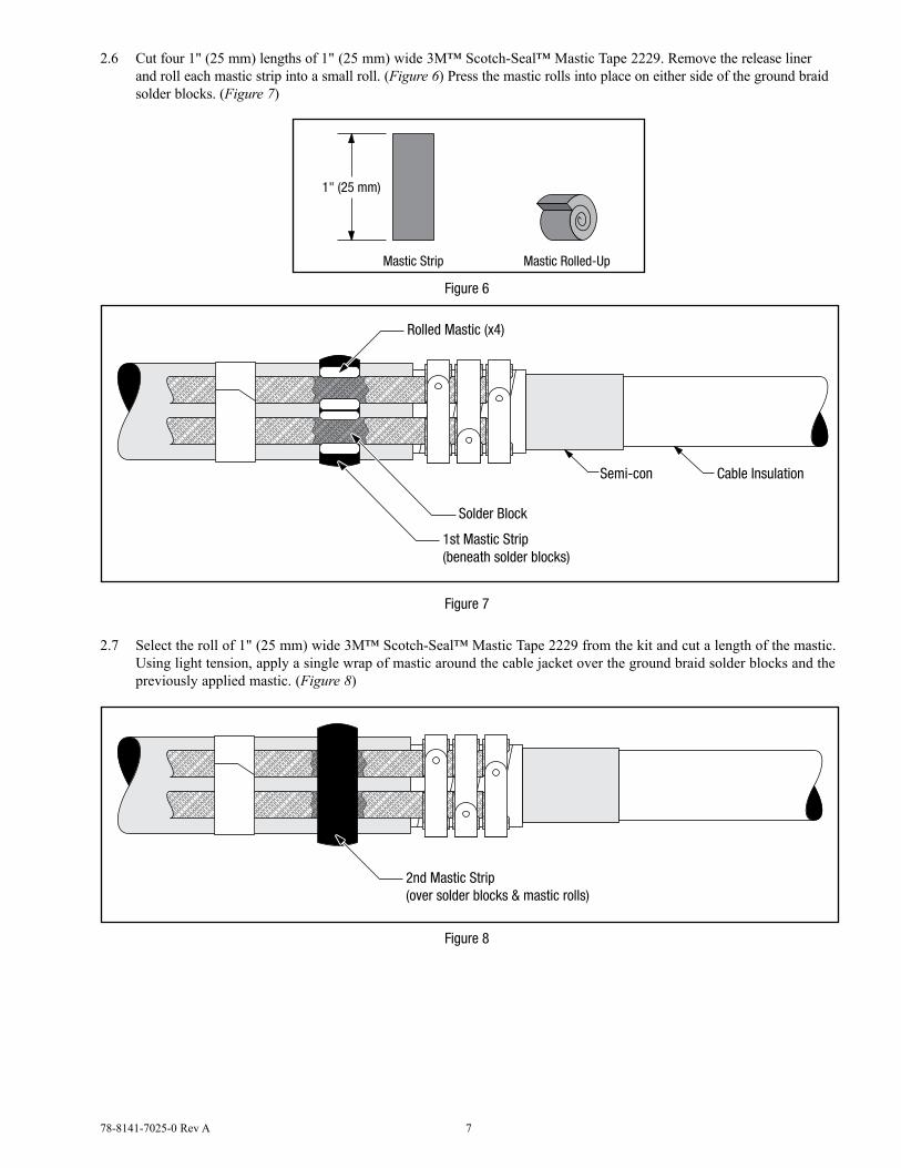
2.6 Cut four 1" (25 mm) lengths of 1" (25 mm) wide 3M™ Scotch-Seal™ Mastic Tape 2229. Remove the release liner and roll each mastic strip into a small roll. (Figure 6) Press the mastic rolls into place on either side of the ground braid solder blocks. (Figure 7)
Mastic Strip Mastic Rolled-Up
1" (25 mm)
Figure 6
Solder Block
1st Mastic Strip(beneath solder blocks)
Rolled Mastic (x4)
Cable InsulationSemi-con
Figure 7
2.7 Select the roll of 1" (25 mm) wide 3M™ Scotch-Seal™ Mastic Tape 2229 from the kit and cut a length of the mastic. Using light tension, apply a single wrap of mastic around the cable jacket over the ground braid solder blocks and the previously applied mastic. (Figure 8)
2nd Mastic Strip(over solder blocks & mastic rolls)
Figure 8
8 78-8141-7025-0 Rev A
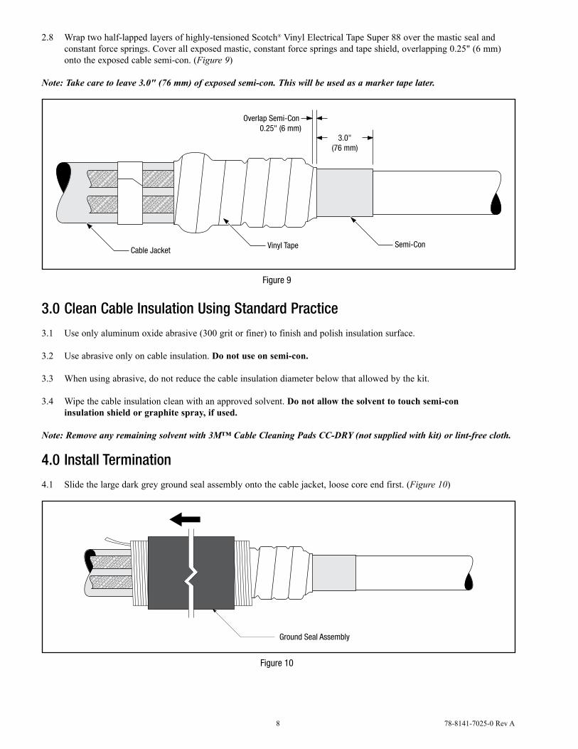
2.8 Wrap two half-lapped layers of highly-tensioned Scotch® Vinyl Electrical Tape Super 88 over the mastic seal and constant force springs. Cover all exposed mastic, constant force springs and tape shield, overlapping 0.25" (6 mm) onto the exposed cable semi-con. (Figure 9)
Note: Take care to leave 3.0" (76 mm) of exposed semi-con. This will be used as a marker tape later.
Cable Jacket
Overlap Semi-Con 0.25" (6 mm)
Vinyl Tape Semi-Con
3.0"(76 mm)
Figure 9
3.0 Clean Cable Insulation Using Standard Practice
3.1 Use only aluminum oxide abrasive (300 grit or finer) to finish and polish insulation surface.
3.2 Use abrasive only on cable insulation. Do not use on semi-con.
3.3 When using abrasive, do not reduce the cable insulation diameter below that allowed by the kit.
3.4 Wipe the cable insulation clean with an approved solvent. Do not allow the solvent to touch semi-con insulation shield or graphite spray, if used.
Note: Remove any remaining solvent with 3M™ Cable Cleaning Pads CC-DRY (not supplied with kit) or lint-free cloth.
4.0 Install Termination
4.1 Slide the large dark grey ground seal assembly onto the cable jacket, loose core end first. (Figure 10)
Ground Seal Assembly
Figure 10
78-8141-7025-0 Rev A 9
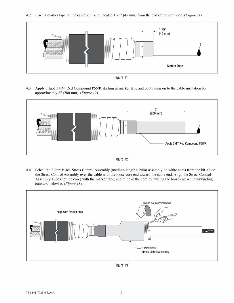
4.2 Place a marker tape on the cable semi-con located 1.75” (45 mm) from the end of the semi-con. (Figure 11)
Marker Tape
1.75"(45 mm)
Figure 11
4.3 Apply 1 tube 3M™ Red Compound P55/R starting at marker tape and continuing on to the cable insulation for approximately 8" (200 mm). (Figure 12)
Apply 3M™ Red Compound P55/R
8"(200 mm)
Figure 12
4.4 Select the 2-Part Black Stress Control Assembly (medium length tubular assembly on white core) from the kit. Slide the Stress Control Assembly over the cable with the loose core end toward the cable end. Align the Stress Control Assembly Tube (not the core) with the marker tape, and remove the core by pulling the loose end while unwinding counterclockwise. (Figure 13)
Unwind counterclockwise
2-Part BlackStress Control Assembly
Align with marker tape
Figure 13
10 78-8141-7025-0 Rev A
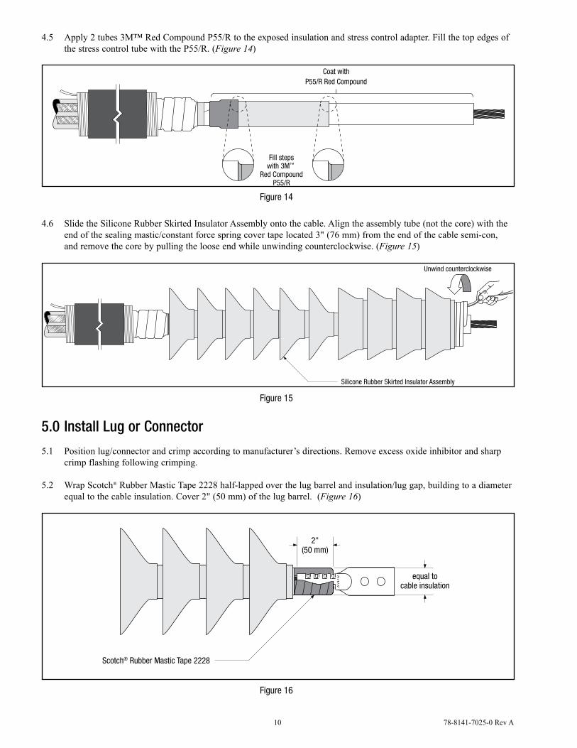
4.5 Apply 2 tubes 3M™ Red Compound P55/R to the exposed insulation and stress control adapter. Fill the top edges of the stress control tube with the P55/R. (Figure 14)
Coat withP55/R Red Compound
Fill stepswith 3M™
Red CompoundP55/R
Figure 14
4.6 Slide the Silicone Rubber Skirted Insulator Assembly onto the cable. Align the assembly tube (not the core) with the end of the sealing mastic/constant force spring cover tape located 3" (76 mm) from the end of the cable semi-con, and remove the core by pulling the loose end while unwinding counterclockwise. (Figure 15)
Unwind counterclockwise
Silicone Rubber Skirted Insulator Assembly
Figure 15
5.0 Install Lug or Connector
5.1 Position lug/connector and crimp according to manufacturer’s directions. Remove excess oxide inhibitor and sharp crimp flashing following crimping.
5.2 Wrap Scotch® Rubber Mastic Tape 2228 half-lapped over the lug barrel and insulation/lug gap, building to a diameter equal to the cable insulation. Cover 2" (50 mm) of the lug barrel. (Figure 16)
Scotch® Rubber Mastic Tape 2228
2"(50 mm)
equal tocable insulation
Figure 16
78-8141-7025-0 Rev A 11
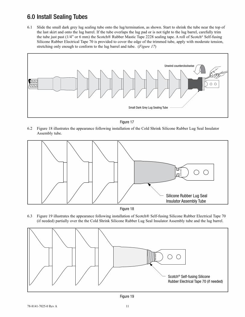
6.0 Install Sealing Tubes
6.1 Slide the small dark grey lug sealing tube onto the lug/termination, as shown. Start to shrink the tube near the top of the last skirt and onto the lug barrel. If the tube overlaps the lug pad or is not tight to the lug barrel, carefully trim the tube just past (1/4” or 6 mm) the Scotch® Rubber Mastic Tape 2228 sealing tape. A roll of Scotch® Self-fusing Silicone Rubber Electrical Tape 70 is provided to cover the edge of the trimmed tube, apply with moderate tension, stretching only enough to conform to the lug barrel and tube. (Figure 17)
Unwind counterclockwise
Small Dark Grey Lug Sealing Tube
Figure 17
6.2 Figure 18 illustrates the appearance following installation of the Cold Shrink Silicone Rubber Lug Seal Insulator Assembly tube.
Silicone Rubber Lug SealInsulator Assembly Tube
Figure 18
6.3 Figure 19 illustrates the appearance following installation of Scotch® Self-fusing Silicone Rubber Electrical Tape 70 (if needed) partially over the the Cold Shrink Silicone Rubber Lug Seal Insulator Assembly tube and the lug barrel.
Scotch® Self-fusing SiliconeRubber Electrical Tape 70 (if needed)
Figure 19
12 78-8141-7025-0 Rev A
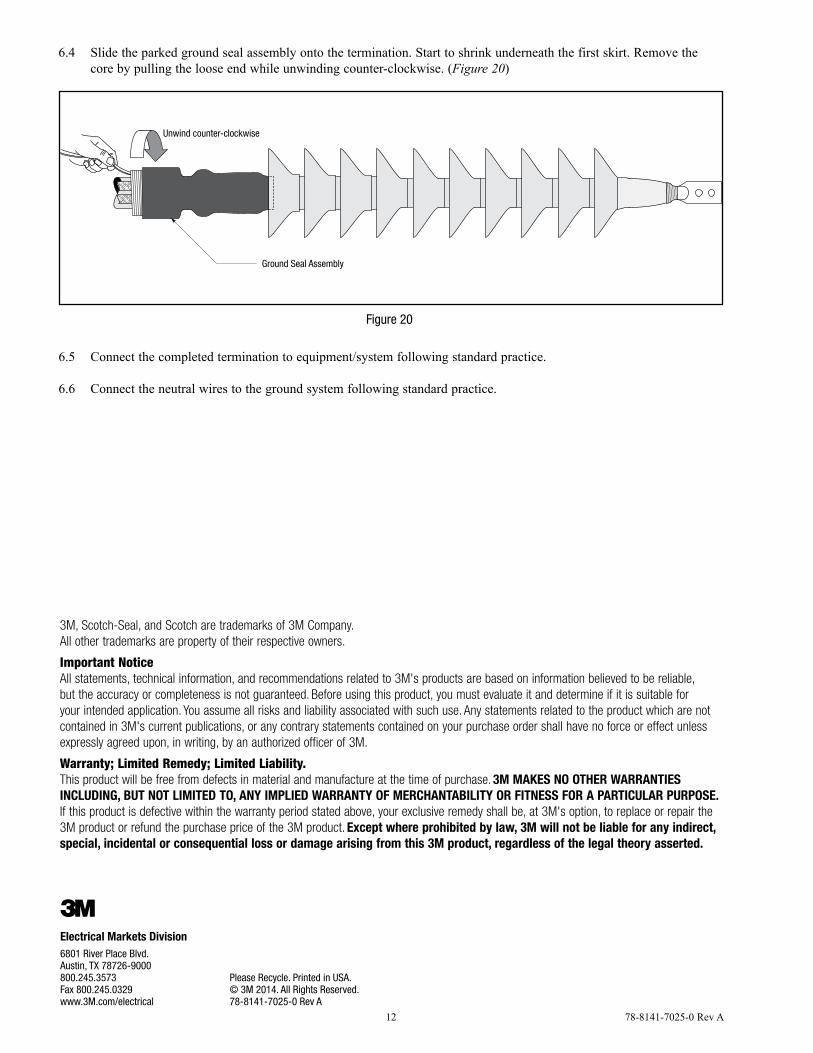
6.4 Slide the parked ground seal assembly onto the termination. Start to shrink underneath the first skirt. Remove the core by pulling the loose end while unwinding counter-clockwise. (Figure 20)
Unwind counter-clockwise
Ground Seal Assembly
Figure 20
6.5 Connect the completed termination to equipment/system following standard practice.
6.6 Connect the neutral wires to the ground system following standard practice.
3M, Scotch-Seal, and Scotch are trademarks of 3M Company. All other trademarks are property of their respective owners.
Important NoticeAll statements, technical information, and recommendations related to 3M's products are based on information believed to be reliable, but the accuracy or completeness is not guaranteed. Before using this product, you must evaluate it and determine if it is suitable for your intended application. You assume all risks and liability associated with such use. Any statements related to the product which are not contained in 3M's current publications, or any contrary statements contained on your purchase order shall have no force or effect unless expressly agreed upon, in writing, by an authorized officer of 3M.
Warranty; Limited Remedy; Limited Liability. This product will be free from defects in material and manufacture at the time of purchase. 3M MAKES NO OTHER WARRANTIES INCLUDING, BUT NOT LIMITED TO, ANY IMPLIED WARRANTY OF MERCHANTABILITY OR FITNESS FOR A PARTICULAR PURPOSE.
If this product is defective within the warranty period stated above, your exclusive remedy shall be, at 3M's option, to replace or repair the 3M product or refund the purchase price of the 3M product. Except where prohibited by law, 3M will not be liable for any indirect, special, incidental or consequential loss or damage arising from this 3M product, regardless of the legal theory asserted.
3Electrical Markets Division6801 River Place Blvd. Austin, TX 78726-9000 800.245.3573Fax 800.245.0329www.3M.com/electrical
Please Recycle. Printed in USA.© 3M 2014. All Rights Reserved.78-8141-7025-0 Rev A