Embed Size (px)
Citation preview
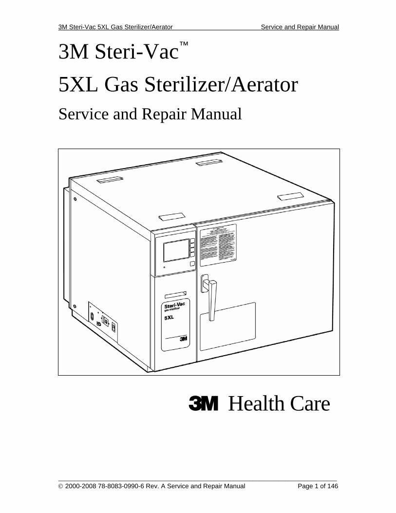
3M Steri-Vac 5XL Gas Sterilizer/Aerator Service and Repair Manual
______________________________________________________________________________________ © 2000-2008 78-8083-0990-6 Rev. A Service and Repair Manual Page 1 of 146
3M Steri-Vac™
5XL Gas Sterilizer/Aerator
Service and Repair Manual
3 Health Care
3M Steri-Vac 5XL Gas Sterilizer/Aerator Service and Repair Manual
______________________________________________________________________________________ © 2000-2008 78-8083-0990-6 Rev. A Service and Repair Manual Page 2 of 146
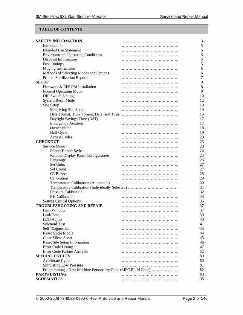
TABLE OF CONTENTS
SAFETY INFORMATION ……………………………………. 3
Introduction ……………………………………. 5 Intended Use Statement ……………………………………. 5 Environmental Operating Conditions ……………………………………. 5 Disposal Information ……………………………………. 5 Fuse Ratings ……………………………………. 5 Moving Instructions ……………………………………. 5 Methods of Selecting Modes and Options ……………………………………. 6 Printed Sterilization Reports ……………………………………. 7
SETUP ……………………………………. 8 Firmware & EPROM Installation ……………………………………. 8 Normal Operating Mode ……………………………………. 9 DIP Switch Settings ……………………………………. 10 System Reset Mode ……………………………………. 12 Site Setup ……………………………………. 13
Modifying Site Setup ……………………………………. 14 Date Format, Time Format, Date, and Time ……………………………………. 15 Daylight Savings Time (DST) ……………………………………. 17 Emergency Aeration ……………………………………. 17 Owner Name ……………………………………. 18 Half Cycle ……………………………………. 19 Access Codes ……………………………………. 20
CHECKOUT ……………………………………. 23 Service Menu ……………………………………. 23
Printer Report Style ……………………………………. 24 Remote Display Panel Configuration ……………………………………. 25 Language ……………………………………. 26 Set Units ……………………………………. 27 Set Count ……………………………………. 27 C3 Buzzer ……………………………………. 28 Calibration ……………………………………. 29 Temperature Calibration (Automatic) ……………………………………. 30 Temperature Calibration (Individually Selected) ………………………..………. 31 Pressure Calibration ……………………………………. 32 RH Calibration ……………………………………. 34
Setting Critical Options ……………………………………. 35 TROUBLESHOOTING AND REPAIR ……………………………………. 37
Help Window ……………………………………. 37 Leak Test ……………………………………. 39 H2O Adjust ……………………………………. 40 Solenoid Test ……………………………………. 41 Self Diagnostics ……………………………………. 43 Reset Cycle to Idle ……………………………………. 44 Clear Silent Abort ……………………………………. 45 Reset Site Setup Information ……………………………………. 46 Error Code Listing ……………………………………. 47 Error Code Failure Analysis ……………………………………. 52
SPECIAL CYCLES ……………………………………. 80 Accelerate Cycle ……………………………………. 80 Simulating Low Pressure ……………………………………. 81 Programming a New Machine Personality Code (MPC Build Code) ……………..…. 82
PARTS LISTING ……………………………………. 83 SCHEMATICS ……………………………………. 135
3M Steri-Vac 5XL Gas Sterilizer/Aerator Service and Repair Manual
______________________________________________________________________________________ © 2000-2008 78-8083-0990-6 Rev. A Service and Repair Manual Page 3 of 146
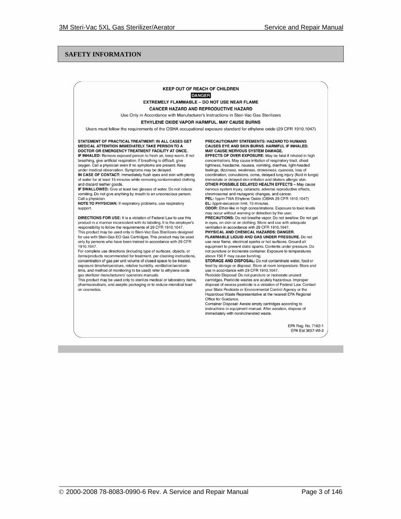
SAFETY INFORMATION
3M Steri-Vac 5XL Gas Sterilizer/Aerator Service and Repair Manual
______________________________________________________________________________________ © 2000-2008 78-8083-0990-6 Rev. A Service and Repair Manual Page 4 of 146
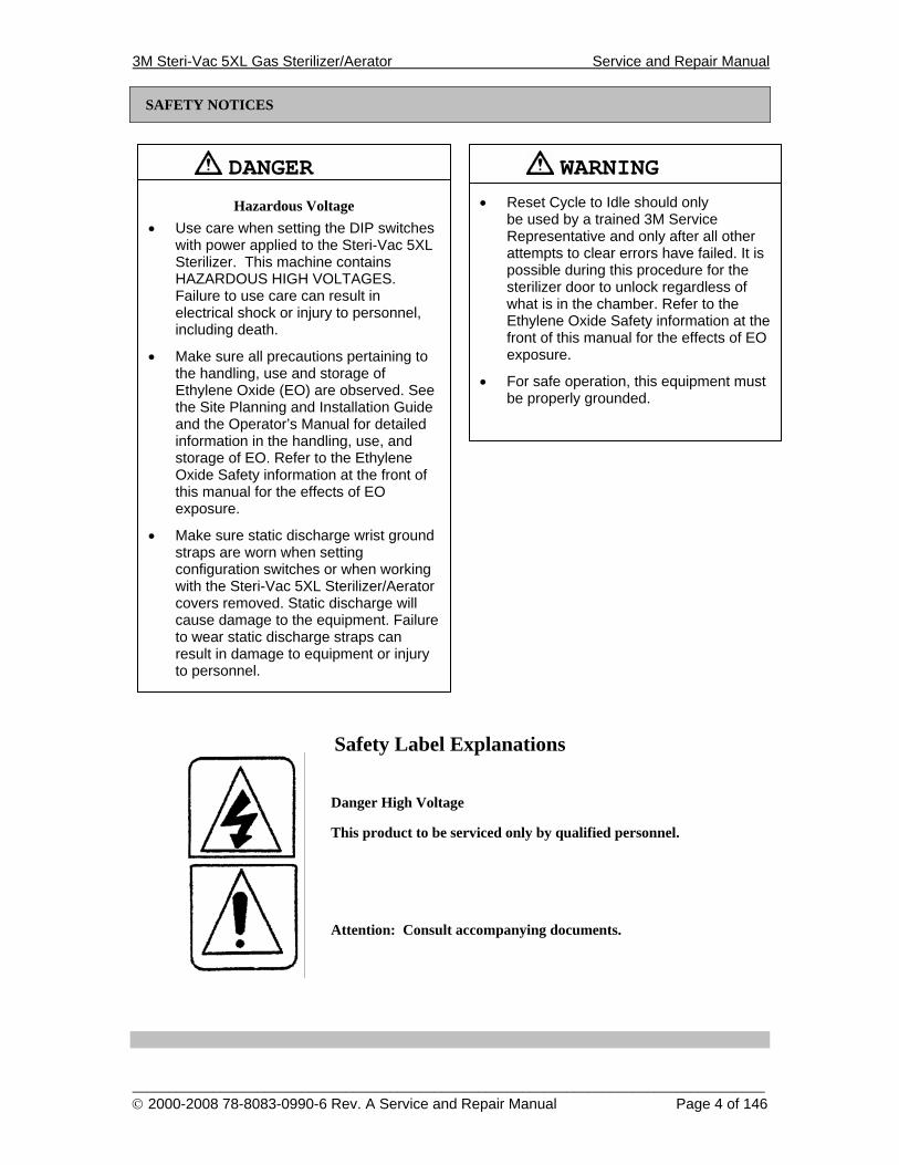
SAFETY NOTICES
Safety Label Explanations
Danger High Voltage
This product to be serviced only by qualified personnel.
Attention: Consult accompanying documents.
DANGER
Hazardous Voltage • Use care when setting the DIP switches
with power applied to the Steri-Vac 5XL Sterilizer. This machine contains HAZARDOUS HIGH VOLTAGES. Failure to use care can result in electrical shock or injury to personnel, including death.
• Make sure all precautions pertaining to the handling, use and storage of Ethylene Oxide (EO) are observed. See the Site Planning and Installation Guide and the Operator’s Manual for detailed information in the handling, use, and storage of EO. Refer to the Ethylene Oxide Safety information at the front of this manual for the effects of EO exposure.
• Make sure static discharge wrist ground straps are worn when setting configuration switches or when working with the Steri-Vac 5XL Sterilizer/Aerator covers removed. Static discharge will cause damage to the equipment. Failure to wear static discharge straps can result in damage to equipment or injury to personnel.
WARNING
• Reset Cycle to Idle should only be used by a trained 3M Service Representative and only after all other attempts to clear errors have failed. It is possible during this procedure for the sterilizer door to unlock regardless of what is in the chamber. Refer to the Ethylene Oxide Safety information at the front of this manual for the effects of EO exposure.
• For safe operation, this equipment must be properly grounded.
3M Steri-Vac 5XL Gas Sterilizer/Aerator Service and Repair Manual
______________________________________________________________________________________ © 2000-2008 78-8083-0990-6 Rev. A Service and Repair Manual Page 5 of 146
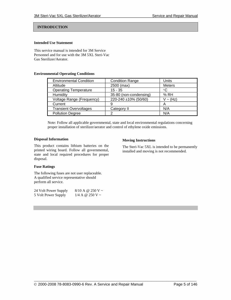
INTRODUCTION
Intended Use Statement
This service manual is intended for 3M Service Personnel and for use with the 3M 5XL Steri-Vac Gas Sterilizer/Aerator.
Environmental Operating Conditions
Environmental Condition Condition Range Units Altitude 2500 (max) Meters Operating Temperature 15 - 35 °C Humidity 35-80 (non-condensing) % RH Voltage Range (Frequency) 220-240 ±10% (50/60) V ~ (Hz) Current 9 A Transient Overvoltages Category II N/A Pollution Degree 2 N/A
Note: Follow all applicable governmental, state and local environmental regulations concerning proper installation of sterilizer/aerator and control of ethylene oxide emissions.
Disposal Information
This product contains lithium batteries on the printed wiring board. Follow all governmental, state and local required procedures for proper disposal.
Fuse Ratings
The following fuses are not user replaceable. A qualified service representative should perform all service. 24 Volt Power Supply 8/10 A @ 250 V ~ 5 Volt Power Supply 1/4 A @ 250 V ~
Moving Instructions
The Steri-Vac 5XL is intended to be permanently installed and moving is not recommended.
3M Steri-Vac 5XL Gas Sterilizer/Aerator Service and Repair Manual
______________________________________________________________________________________ © 2000-2008 78-8083-0990-6 Rev. A Service and Repair Manual Page 6 of 146
INTRODUCTION
Note: The service representative access code (the “Master Code”) is encoded in the software to prevent unauthorized access to some options.
This access code is provided to the service representative upon request.
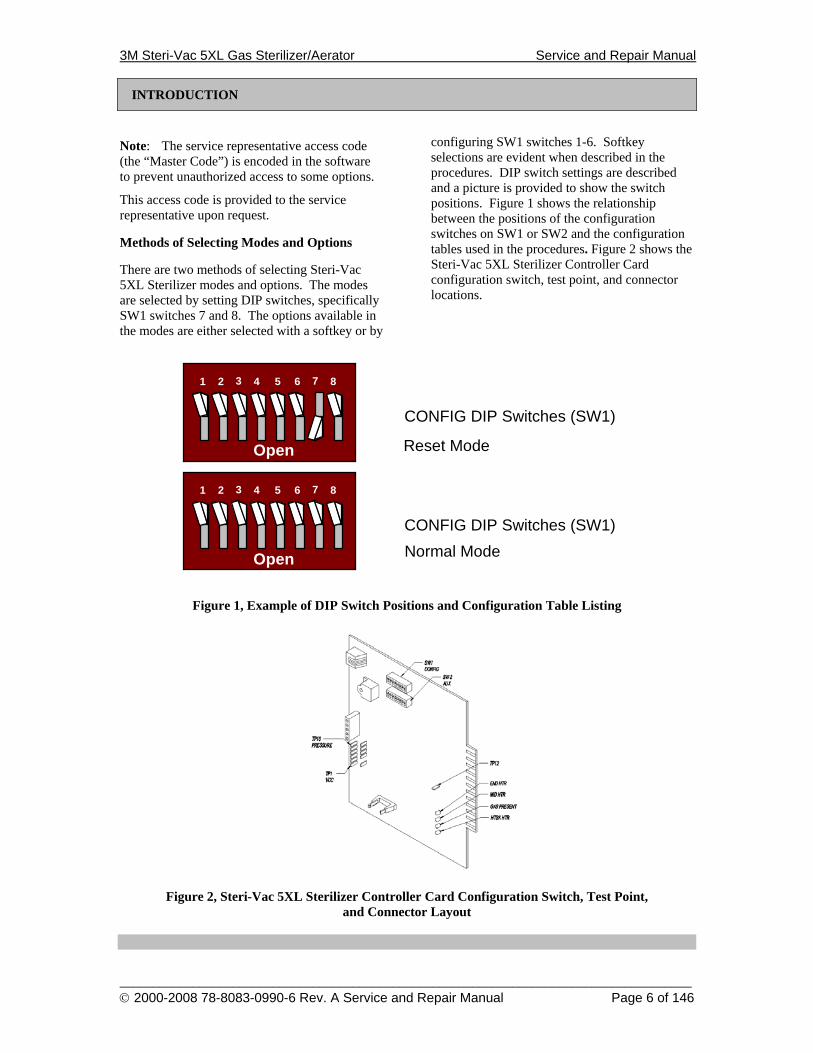
Methods of Selecting Modes and Options
There are two methods of selecting Steri-Vac 5XL Sterilizer modes and options. The modes are selected by setting DIP switches, specifically SW1 switches 7 and 8. The options available in the modes are either selected with a softkey or by
configuring SW1 switches 1-6. Softkey selections are evident when described in the procedures. DIP switch settings are described and a picture is provided to show the switch positions. Figure 1 shows the relationship between the positions of the configuration switches on SW1 or SW2 and the configuration tables used in the procedures. Figure 2 shows the Steri-Vac 5XL Sterilizer Controller Card configuration switch, test point, and connector locations.
Open
1 2 3 4
CONFIG DIP Switches (SW1)
5 6 7 8
Open
1 2 3 4
CONFIG DIP Switches (SW1)
5 6 7 8
Reset Mode
Normal Mode
Figure 1, Example of DIP Switch Positions and Configuration Table Listing
Figure 2, Steri-Vac 5XL Sterilizer Controller Card Configuration Switch, Test Point,
and Connector Layout
3M Steri-Vac 5XL Gas Sterilizer/Aerator Service and Repair Manual
______________________________________________________________________________________ © 2000-2008 78-8083-0990-6 Rev. A Service and Repair Manual Page 7 of 146
INTRODUCTION
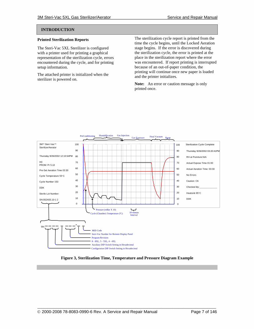
Printed Sterilization Reports
The Steri-Vac 5XL Sterilizer is configured with a printer used for printing a graphical representation of the sterilization cycle, errors encountered during the cycle, and for printing setup information.
The attached printer is initialized when the sterilizer is powered on.
The sterilization cycle report is printed from the time the cycle begins, until the Locked Aeration stage begins. If the error is discovered during the sterilization cycle, the error is printed at the place in the sterilization report where the error was encountered. If report printing is interrupted because of an out-of-paper condition, the printing will continue once new paper is loaded and the printer initializes.
Note: An error or caution message is only printed once.
Figure 3, Sterilization Time, Temperature and Pressure Diagram Example
Gas InjectionGas Exposure
PreConditioning
0 10 20 30 40 50 60 70 80 90 100
Purge
SN:002A55.10-1 2 Sterile Lot Number: DDK
Pre-Set Aeration Time 03:30
PROM: Pr 5.10
Thursday 9/26/2002 12:10:54PM
Sterilizer/Aerator 3M™ Steri-Vac™
Cycle Temperature 55°C Cycle Number 153
DDK Heatsink 95°C Checked By:______________
Caution: C6 No Errors
Actual Expose Time 01:00
Actual Aeration Time: 03:30
RH at Puncture:N/A
Thursday 9/26/2002 03:20:41PM
Sterilization Cycle Complete
Final Vacuum
HC
10-minuteInterval
Pressure (mBar X 10)
Cycle (Chamber) Temperature ( C)
Humidification
SN: MID Code Steri-Vac Number for Remote Display PanelProgram Revision8 - 8XL, 5 - 5XL, 4 - 4XLAuxiliary DIP Switch Setting in HexadecimalConfiguration DIP Switch Setting in Hexadecimal
0 10 20 30 40 50 60 70 80 90 100
3M Steri-Vac 5XL Gas Sterilizer/Aerator Service and Repair Manual
______________________________________________________________________________________ © 2000-2008 78-8083-0990-6 Rev. A Service and Repair Manual Page 8 of 146
SETUP
Setup
Firmware Installation
This procedure upgrades the sterilizer software to version Pr 5.11 from any previous version. This procedure must not be used to stop a sterilization cycle.
WARNING
To reduce the risks associated with the use of ethylene oxide gas, which, if not avoided, could result in death or serious injury (and/or property damage), do not perform this Firmware Installation procedure with either ethylene oxide gas or a Steri-Gas™ cartridge in the chamber.
Follow these seven steps in this order:
1. EPROM Installation 2. Reset Site Setup Information 3. Reset Cycle To Idle 4. Program New Machine Personality
Code 5. Reset Site Setup Information 6. Reset Cycle To Idle 7. Normal Operating Mode
For the purpose of this Firmware Installation procedure, when performing the Reset Site Setup Information and Reset Cycle To Idle procedures, turn off the sterilizer power after the copyright screen appears and continue with the next step of this Firmware Installation procedure. Note: This Firmware Installation procedure must also be followed if, for some reason, it is necessary to switch back to a previous sterilizer software version.
EPROM Installation 1. Turn the power off to the sterilizer and
remove the left side service panel. Attach your wrist-grounding strap to the sterilizer chassis ground.
2. Remove the existing EPROM and install the replacement EPROM.
!
3M Steri-Vac 5XL Gas Sterilizer/Aerator Service and Repair Manual
______________________________________________________________________________________ © 2000-2008 78-8083-0990-6 Rev. A Service and Repair Manual Page 9 of 146
SETUP
Setup
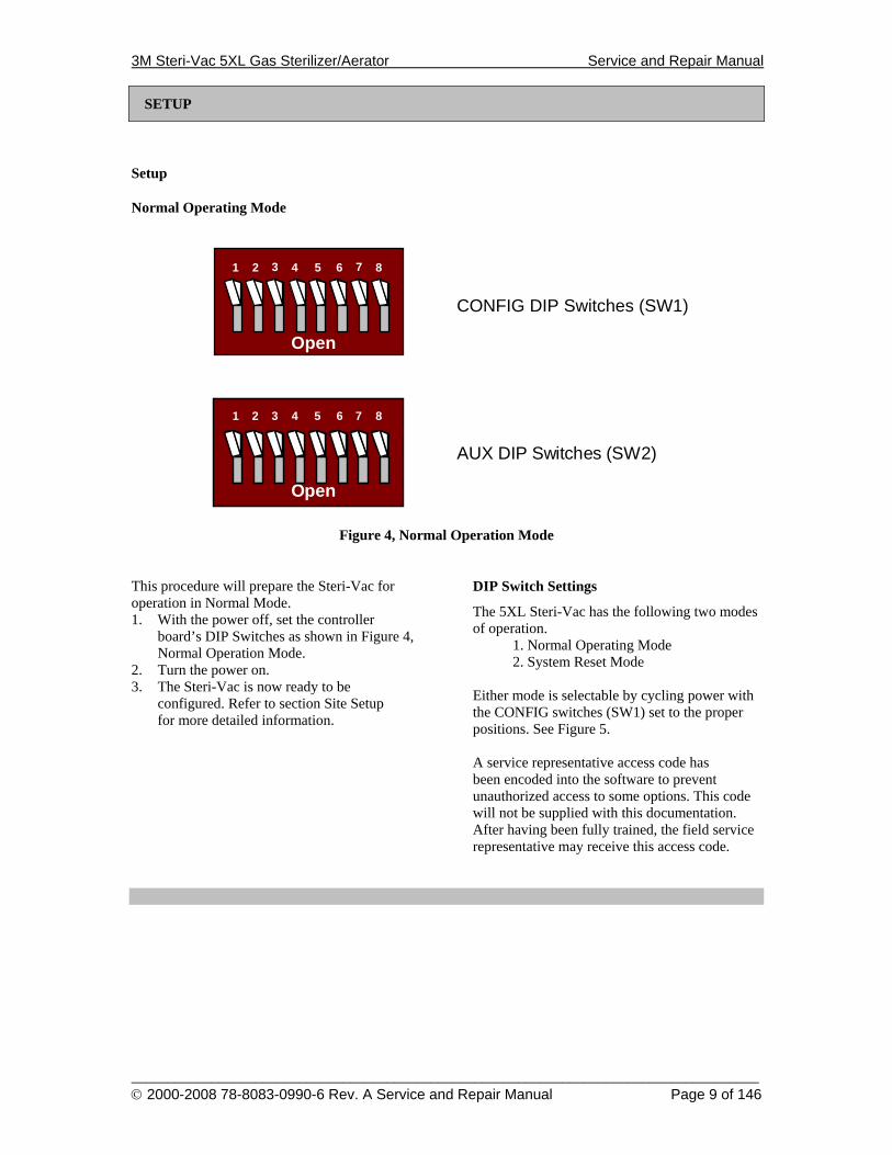
Normal Operating Mode
Open
1 2 3 4
CONFIG DIP Switches (SW1)
5 6 7 8
Open
1 2 3 4
AUX DIP Switches (SW2)
5 6 7 8
Figure 4, Normal Operation Mode
This procedure will prepare the Steri-Vac for operation in Normal Mode. 1. With the power off, set the controller
board’s DIP Switches as shown in Figure 4, Normal Operation Mode.
2. Turn the power on. 3. The Steri-Vac is now ready to be
configured. Refer to section Site Setup for more detailed information.
DIP Switch Settings
The 5XL Steri-Vac has the following two modes of operation.
1. Normal Operating Mode 2. System Reset Mode
Either mode is selectable by cycling power with the CONFIG switches (SW1) set to the proper positions. See Figure 5. A service representative access code has been encoded into the software to prevent unauthorized access to some options. This code will not be supplied with this documentation. After having been fully trained, the field service representative may receive this access code.
3M Steri-Vac 5XL Gas Sterilizer/Aerator Service and Repair Manual
______________________________________________________________________________________ © 2000-2008 78-8083-0990-6 Rev. A Service and Repair Manual Page 10 of 146
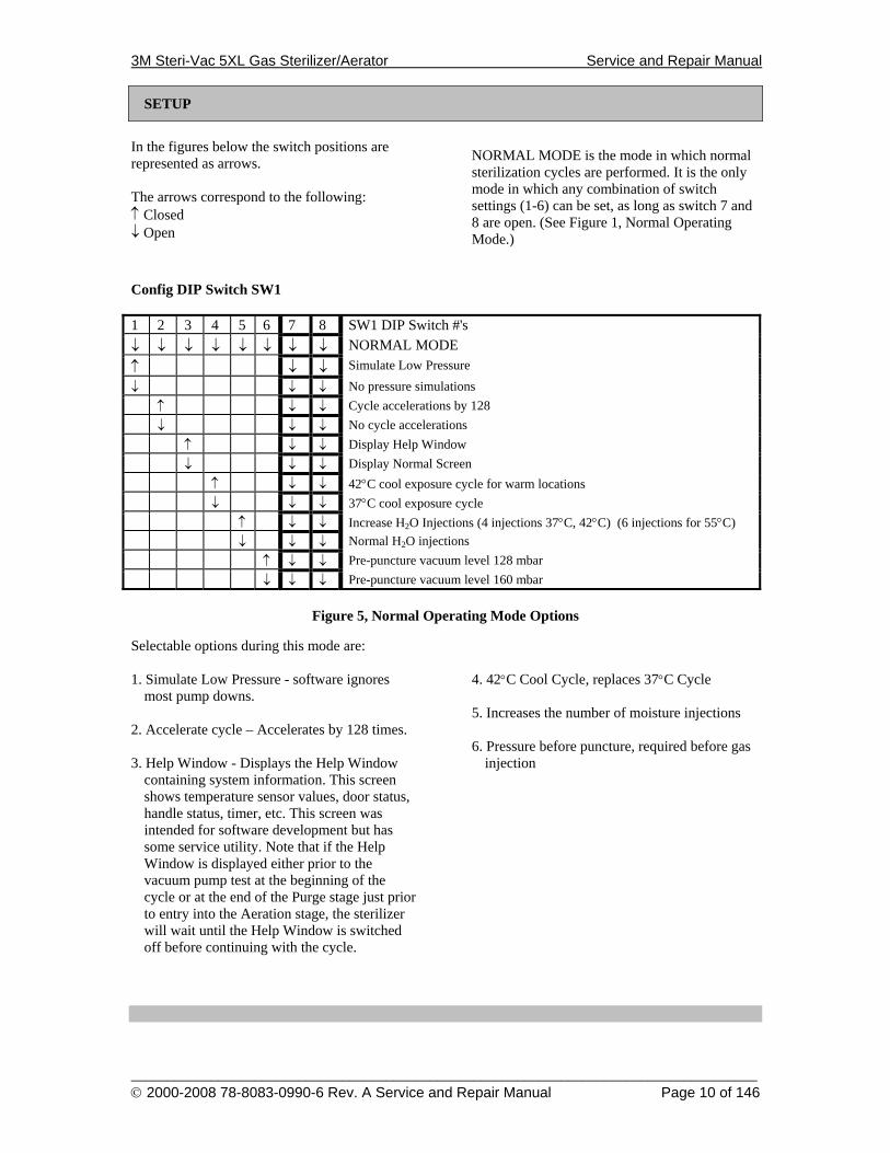
SETUP
In the figures below the switch positions are represented as arrows. The arrows correspond to the following: ↑ Closed ↓ Open
NORMAL MODE is the mode in which normal sterilization cycles are performed. It is the only mode in which any combination of switch settings (1-6) can be set, as long as switch 7 and 8 are open. (See Figure 1, Normal Operating Mode.)
Config DIP Switch SW1 1 2 3 4 5 6 7 8 SW1 DIP Switch #'s ↓ ↓ ↓ ↓ ↓ ↓ ↓ ↓ NORMAL MODE ↑ ↓ ↓ Simulate Low Pressure
↓ ↓ ↓ No pressure simulations ↑ ↓ ↓ Cycle accelerations by 128 ↓ ↓ ↓ No cycle accelerations ↑ ↓ ↓ Display Help Window ↓ ↓ ↓ Display Normal Screen ↑ ↓ ↓ 42°C cool exposure cycle for warm locations ↓ ↓ ↓ 37°C cool exposure cycle ↑ ↓ ↓ Increase H2O Injections (4 injections 37°C, 42°C) (6 injections for 55°C) ↓ ↓ ↓ Normal H2O injections ↑ ↓ ↓ Pre-puncture vacuum level 128 mbar ↓ ↓ ↓ Pre-puncture vacuum level 160 mbar
Figure 5, Normal Operating Mode Options
Selectable options during this mode are: 1. Simulate Low Pressure - software ignores
most pump downs. 2. Accelerate cycle – Accelerates by 128 times. 3. Help Window - Displays the Help Window
containing system information. This screen shows temperature sensor values, door status, handle status, timer, etc. This screen was intended for software development but has some service utility. Note that if the Help Window is displayed either prior to the vacuum pump test at the beginning of the cycle or at the end of the Purge stage just prior to entry into the Aeration stage, the sterilizer will wait until the Help Window is switched off before continuing with the cycle.
4. 42°C Cool Cycle, replaces 37°C Cycle 5. Increases the number of moisture injections 6. Pressure before puncture, required before gas
injection
3M Steri-Vac 5XL Gas Sterilizer/Aerator Service and Repair Manual
______________________________________________________________________________________ © 2000-2008 78-8083-0990-6 Rev. A Service and Repair Manual Page 11 of 146
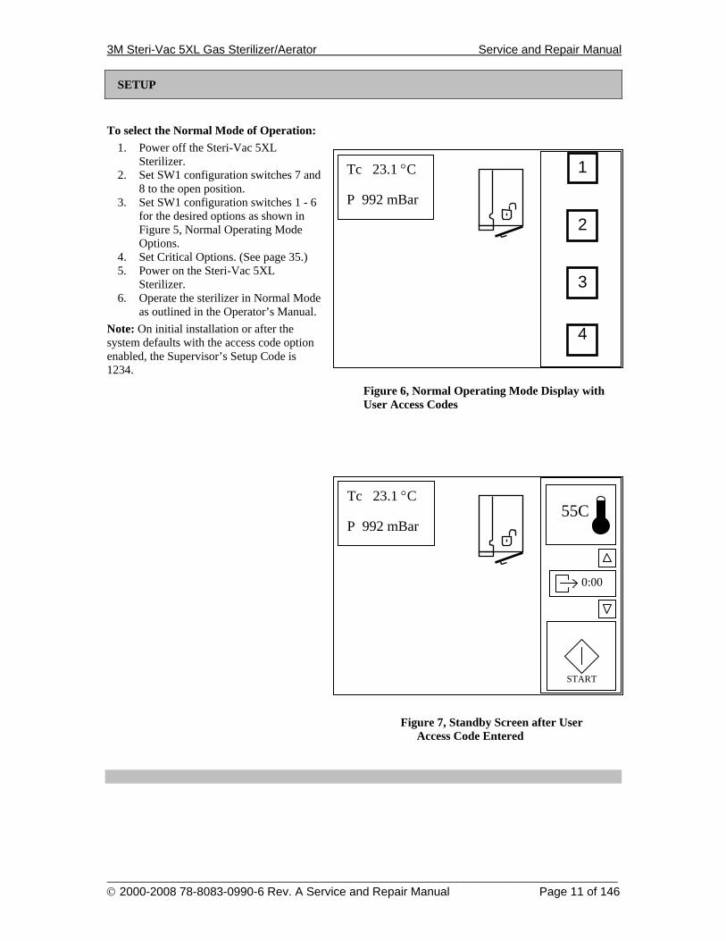
SETUP
To select the Normal Mode of Operation: 1. Power off the Steri-Vac 5XL
Sterilizer. 2. Set SW1 configuration switches 7 and
8 to the open position. 3. Set SW1 configuration switches 1 - 6
for the desired options as shown in Figure 5, Normal Operating Mode Options.
4. Set Critical Options. (See page 35.) 5. Power on the Steri-Vac 5XL
Sterilizer. 6. Operate the sterilizer in Normal Mode
as outlined in the Operator’s Manual. Note: On initial installation or after the system defaults with the access code option enabled, the Supervisor’s Setup Code is 1234.
Figure 6, Normal Operating Mode Display with User Access Codes
Figure 7, Standby Screen after User Access Code Entered
START
55C
0:00
Tc 23.1 °C P 992 mBar
1
2
3
4
Tc 23.1 °C P 992 mBar

3M Steri-Vac 5XL Gas Sterilizer/Aerator Service and Repair Manual
______________________________________________________________________________________ © 2000-2008 78-8083-0990-6 Rev. A Service and Repair Manual Page 12 of 146
SETUP
System Reset Mode
Reset Cycle to Idle This switch setting is for development purposes only. After cycling power, the software will ask for the Master Code. If the correct code is given, the Door will UNLOCK, and the chamber will equalize. All cycle information will be reset (except cycle count). Clear Analog Sensor Offsets This setting, after cycling power, will clear the analog sensor offsets to zero. These offsets are the calibration adjustments determined at the time of manufacturing. After calibrating the sensors, these new offsets are restored. Clear Silent Abort If an Abator Lockout error (E9 or E78) or a Silent Abort error (E73 or E75) occurs, place CONFIG Dip Switch settings to Clear Silent
Abort shown in Figure 8, System Reset Mode. (The Master Code may also be required.) The software will automatically clear the error(s) and restart the last stage of the cycle. This Dip Switch setting will also clear E1, and E2. However these errors indicate memory communications problems and may be unrecoverable until U24 is replaced, Reset Site Setup and Reset Cycle to Idle are performed. Reset Site Setup This setting clears all memory and resets the program parameters to their default settings. After this reset the default setting for the stage of the cycle is Final Vacuum. After the Steri-Vac performs the final vacuum, flushing, and aeration, the door will unlock. This setting is intended for manufacturing purposes but allows the service representative to completely default all variable settings.
1 2 3 4 5 6 7 8 SW1 DIP Switch #'s ↓ ↓ ↓ ↓ ↓ ↓ ↑ ↓ Reset Cycle to Idle ↓ ↓ ↓ ↓ ↓ ↑ ↑ ↓ Unused ↓ ↓ ↓ ↓ ↑ ↓ ↑ ↓ Unused ↓ ↓ ↓ ↑ ↓ ↓ ↑ ↓ Clear Analog Sensor Offsets ↓ ↓ ↑ ↓ ↓ ↓ ↑ ↓ Clear Silent Abort ↓ ↑ ↓ ↓ ↓ ↓ ↑ ↓ Reset Site Setup ↑ ↓ ↓ ↓ ↓ ↓ ↑ ↓ Unused
Figure 8, System Reset Mode
3M Steri-Vac 5XL Gas Sterilizer/Aerator Service and Repair Manual
______________________________________________________________________________________ © 2000-2008 78-8083-0990-6 Rev. A Service and Repair Manual Page 13 of 146
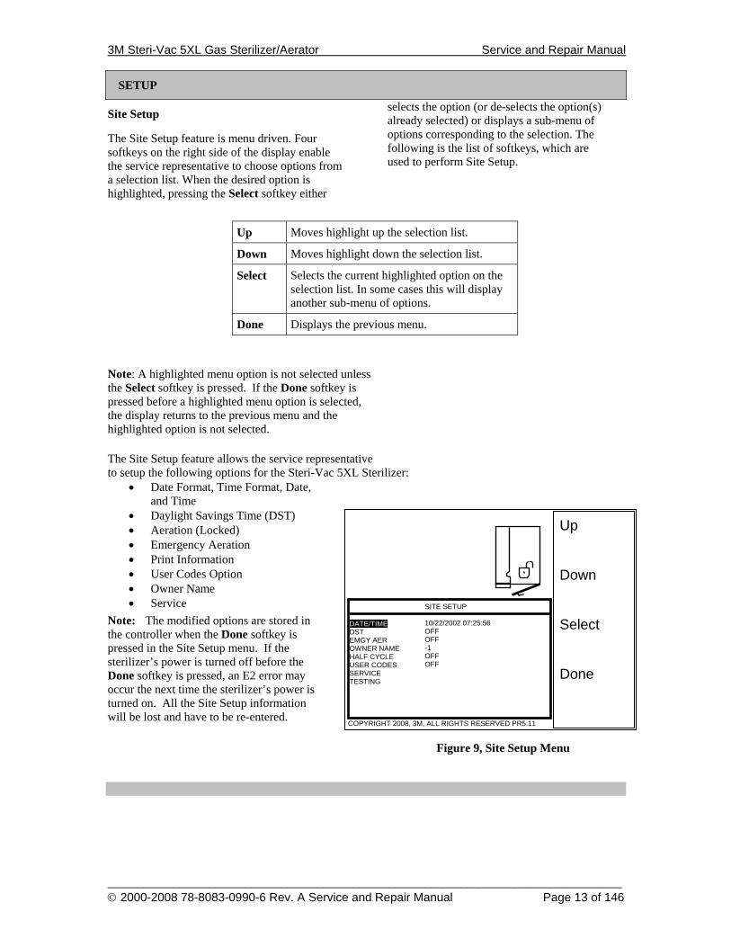
Up Down Select Done
DATE/TIME DST EMGY AER OWNER NAME HALF CYCLE USER CODES SERVICE TESTING
COPYRIGHT 2008, 3M, ALL RIGHTS RESERVED PR5.11
SITE SETUP 10/22/2002 07:25:56 OFF OFF -1 OFF OFF
SETUP
Site Setup
The Site Setup feature is menu driven. Four softkeys on the right side of the display enable the service representative to choose options from a selection list. When the desired option is highlighted, pressing the Select softkey either
selects the option (or de-selects the option(s) already selected) or displays a sub-menu of options corresponding to the selection. The following is the list of softkeys, which are used to perform Site Setup.
Up Moves highlight up the selection list.
Down Moves highlight down the selection list.
Select Selects the current highlighted option on the selection list. In some cases this will display another sub-menu of options.
Done Displays the previous menu.
Note: A highlighted menu option is not selected unless the Select softkey is pressed. If the Done softkey is pressed before a highlighted menu option is selected, the display returns to the previous menu and the highlighted option is not selected. The Site Setup feature allows the service representative to setup the following options for the Steri-Vac 5XL Sterilizer:
• Date Format, Time Format, Date, and Time
• Daylight Savings Time (DST) • Aeration (Locked) • Emergency Aeration • Print Information • User Codes Option • Owner Name • Service
Note: The modified options are stored in the controller when the Done softkey is pressed in the Site Setup menu. If the sterilizer’s power is turned off before the Done softkey is pressed, an E2 error may occur the next time the sterilizer’s power is turned on. All the Site Setup information will be lost and have to be re-entered.
Figure 9, Site Setup Menu
3M Steri-Vac 5XL Gas Sterilizer/Aerator Service and Repair Manual
______________________________________________________________________________________ © 2000-2008 78-8083-0990-6 Rev. A Service and Repair Manual Page 14 of 146
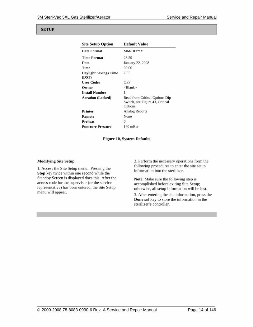
SETUP
Site Setup Option Default Value Date Format MM/DD/YY
Time Format 23:59 Date January 22, 2008 Time 00:00 Daylight Savings Time (DST)
OFF
User Codes OFF Owner <Blank> Install Number 1 Aeration (Locked) Read from Critical Options Dip
Switch, see Figure 43, Critical Options
Printer Analog Reports Remote None Preheat 0 Puncture Pressure 160 mBar
Figure 10, System Defaults
Modifying Site Setup
1. Access the Site Setup menu. Pressing the Stop key twice within one second while the Standby Screen is displayed does this. After the access code for the supervisor (or the service representative) has been entered, the Site Setup menu will appear.
2. Perform the necessary operations from the following procedures to enter the site setup information into the sterilizer.
Note: Make sure the following step is accomplished before exiting Site Setup; otherwise, all setup information will be lost. 3. After entering the site information, press the Done softkey to store the information in the sterilizer’s controller.
3M Steri-Vac 5XL Gas Sterilizer/Aerator Service and Repair Manual
______________________________________________________________________________________ © 2000-2008 78-8083-0990-6 Rev. A Service and Repair Manual Page 15 of 146
Up Down Select Done
DATE FORMAT
COPYRIGHT 2008, 3M, ALL RIGHTS RESERVED PR5.11
MM/DD/YYMM-DD-YY DD/MM/YY DD-MM-YY YY/MM/DD
Up Down Select Done
DATE/TIME DST EMGY AER OWNER NAME HALF CYCLE USER CODES SERVICE TESTING
COPYRIGHT 2008, 3M, ALL RIGHTS RESERVED PR5.11
SITE SETUP 10/22/2002 07:25:56 OFF OFF -1 OFF
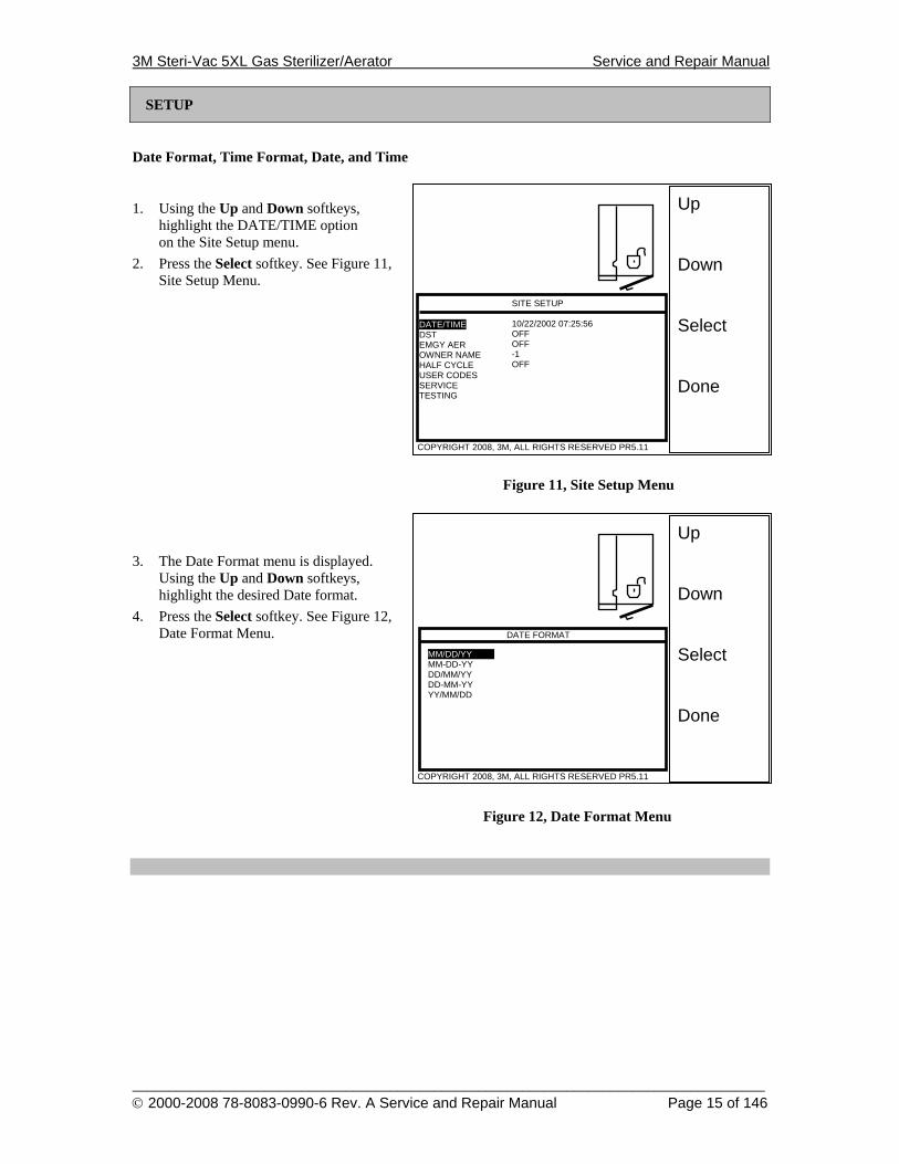
SETUP
Date Format, Time Format, Date, and Time
1. Using the Up and Down softkeys, highlight the DATE/TIME option on the Site Setup menu.
2. Press the Select softkey. See Figure 11, Site Setup Menu.
Figure 11, Site Setup Menu 3. The Date Format menu is displayed.
Using the Up and Down softkeys, highlight the desired Date format.
4. Press the Select softkey. See Figure 12, Date Format Menu.
Figure 12, Date Format Menu
3M Steri-Vac 5XL Gas Sterilizer/Aerator Service and Repair Manual
______________________________________________________________________________________ © 2000-2008 78-8083-0990-6 Rev. A Service and Repair Manual Page 16 of 146
Up Down Select Done
TIME FORMAT
COPYRIGHT 2008, 3M, ALL RIGHTS RESERVED PR5.11
24:0024.00 12:00 12.00
Hours Up Minutes Up Minutes Down Save Time
SET TIME
COPYRIGHT 2008, 3M, ALL RIGHTS RESERVED PR5.11
07:25
SETUP
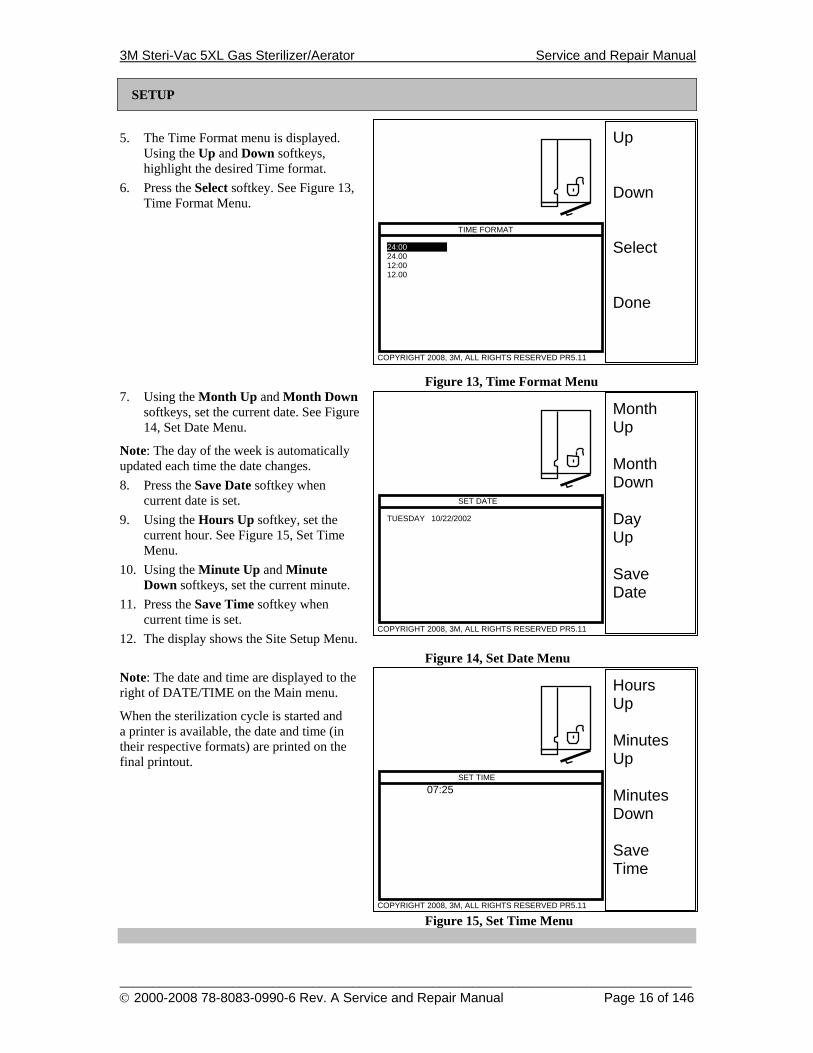
5. The Time Format menu is displayed.
Using the Up and Down softkeys, highlight the desired Time format.
6. Press the Select softkey. See Figure 13, Time Format Menu.
Figure 13, Time Format Menu 7. Using the Month Up and Month Down
softkeys, set the current date. See Figure 14, Set Date Menu.
Note: The day of the week is automatically updated each time the date changes. 8. Press the Save Date softkey when
current date is set. 9. Using the Hours Up softkey, set the
current hour. See Figure 15, Set Time Menu.
10. Using the Minute Up and Minute Down softkeys, set the current minute.
11. Press the Save Time softkey when current time is set.
12. The display shows the Site Setup Menu. Figure 14, Set Date Menu
Note: The date and time are displayed to the right of DATE/TIME on the Main menu.
When the sterilization cycle is started and a printer is available, the date and time (in their respective formats) are printed on the final printout.
Figure 15, Set Time Menu
SET DATE
TUESDAY 10/22/2002
Month Up Month Down Day Up Save Date
COPYRIGHT 2008, 3M, ALL RIGHTS RESERVED PR5.11
3M Steri-Vac 5XL Gas Sterilizer/Aerator Service and Repair Manual
______________________________________________________________________________________ © 2000-2008 78-8083-0990-6 Rev. A Service and Repair Manual Page 17 of 146
Up Down Select Done
DATE/TIME DST EMGY AER OWNER NAME HALF CYCLE USER CODES SERVICE TESTING
COPYRIGHT 2008, 3M, ALL RIGHTS RESERVED PR5.11
SITE SETUP 10/22/2002 07:25:56 OFF OFF -1 OFF
SETUP
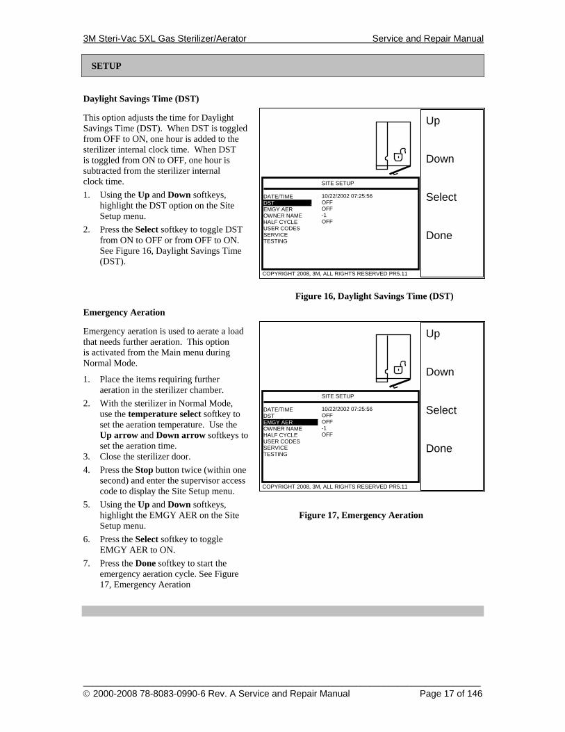
Daylight Savings Time (DST)
This option adjusts the time for Daylight Savings Time (DST). When DST is toggled from OFF to ON, one hour is added to the sterilizer internal clock time. When DST is toggled from ON to OFF, one hour is subtracted from the sterilizer internal clock time. 1. Using the Up and Down softkeys,
highlight the DST option on the Site Setup menu.
2. Press the Select softkey to toggle DST from ON to OFF or from OFF to ON. See Figure 16, Daylight Savings Time (DST).
Figure 16, Daylight Savings Time (DST)
Emergency Aeration
Emergency aeration is used to aerate a load that needs further aeration. This option is activated from the Main menu during Normal Mode.
1. Place the items requiring further aeration in the sterilizer chamber.
2. With the sterilizer in Normal Mode, use the temperature select softkey to set the aeration temperature. Use the Up arrow and Down arrow softkeys to set the aeration time.
3. Close the sterilizer door. 4. Press the Stop button twice (within one
second) and enter the supervisor access code to display the Site Setup menu.
5. Using the Up and Down softkeys, highlight the EMGY AER on the Site Figure 17, Emergency Aeration Setup menu.
6. Press the Select softkey to toggle EMGY AER to ON.
7. Press the Done softkey to start the emergency aeration cycle. See Figure 17, Emergency Aeration
Up Down Select Done
DATE/TIME DST . EMGY AER OWNER NAME HALF CYCLE USER CODES SERVICE TESTING
COPYRIGHT 2008, 3M, ALL RIGHTS RESERVED PR5.11
SITE SETUP 10/22/2002 07:25:56 OFF OFF -1 OFF
3M Steri-Vac 5XL Gas Sterilizer/Aerator Service and Repair Manual
______________________________________________________________________________________ © 2000-2008 78-8083-0990-6 Rev. A Service and Repair Manual Page 18 of 146
Up Down Select Done
DATE/TIME DST EMGY AER OWNER NAME HALF CYCLE USER CODES SERVICE TESTING
COPYRIGHT 2008, 3M, ALL RIGHTS RESERVED PR5.11
SITE SETUP 10/22/2002 07:25:56 OFF OFF -1 OFF
SETUP
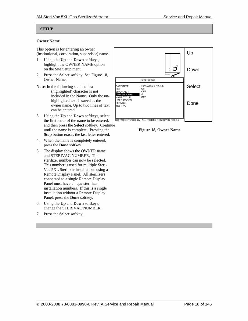
Owner Name
This option is for entering an owner (institutional, corporation, supervisor) name. 1. Using the Up and Down softkeys,
highlight the OWNER NAME option on the Site Setup menu.
2. Press the Select softkey. See Figure 18, Owner Name.
Note: In the following step the last (highlighted) character is not included in the Name. Only the un-highlighted text is saved as the owner name. Up to two lines of text can be entered.
3. Using the Up and Down softkeys, select the first letter of the name to be entered, and then press the Select softkey. Continue until the name is complete. Pressing the Figure 18, Owner Name Stop button erases the last letter entered.
4. When the name is completely entered, press the Done softkey.
5. The display shows the OWNER name and STERIVAC NUMBER. The sterilizer number can now be selected. This number is used for multiple Steri-Vac 5XL Sterilizer installations using a Remote Display Panel. All sterilizers connected to a single Remote Display Panel must have unique sterilizer installation numbers. If this is a single installation without a Remote Display Panel, press the Done softkey.
6. Using the Up and Down softkeys, change the STERIVAC NUMBER.
7. Press the Select softkey.
3M Steri-Vac 5XL Gas Sterilizer/Aerator Service and Repair Manual
______________________________________________________________________________________ © 2000-2008 78-8083-0990-6 Rev. A Service and Repair Manual Page 19 of 146
Up Down Select Done
DATE/TIME DST EMGY AER OWNER NAME HALF CYCLE USER CODES SERVICE TESTING
COPYRIGHT 2008, 3M, ALL RIGHTS RESERVED PR5.11
SITE SETUP 10/22/2002 07:25:56 OFF OFF -1 ON
SETUP
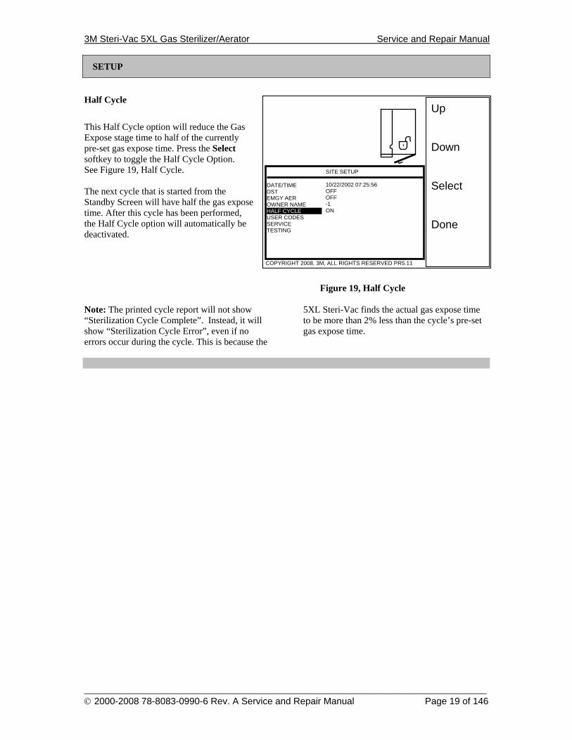
Half Cycle
This Half Cycle option will reduce the Gas Expose stage time to half of the currently pre-set gas expose time. Press the Select softkey to toggle the Half Cycle Option. See Figure 19, Half Cycle. The next cycle that is started from the Standby Screen will have half the gas expose time. After this cycle has been performed, the Half Cycle option will automatically be deactivated.
Figure 19, Half Cycle Note: The printed cycle report will not show “Sterilization Cycle Complete”. Instead, it will show “Sterilization Cycle Error”, even if no errors occur during the cycle. This is because the
5XL Steri-Vac finds the actual gas expose time to be more than 2% less than the cycle’s pre-set gas expose time.

3M Steri-Vac 5XL Gas Sterilizer/Aerator Service and Repair Manual
______________________________________________________________________________________ © 2000-2008 78-8083-0990-6 Rev. A Service and Repair Manual Page 20 of 146
Up Down Select Done
DATE/TIME DST EMGY AER OWNER NAME HALF CYCLE USER CODES SERVICE TESTING
COPYRIGHT 2008, 3M, ALL RIGHTS RESERVED PR5.11
SITE SETUP 10/22/2002 07:25:56 OFF OFF -1 OFF OFF
Up Down Select Done
Ο SETUP - USER#1 - USER#2 - USER#3 - USER#4 - USER#5 - USER#6 - USER#7
COPYRIGHT 2008, 3M, ALL RIGHTS RESERVED PR5.11
ACCESS CODES :1234: :: :: :: :: :: :: ::
SETUP
Access Codes
A. Introduction The use of access codes is optional on the 5XL sterilizer. When this option is enabled, an access code is required to gain access to the Standby Screen of the sterilizer, for starting a cycle, for ending a cycle in which an error occurs, and for altering the site setup information. For each
access code, an ID is assigned. This ID will be printed on the report header when a sterilization cycle is started. The ID of the user who stops the cycle will be printed on the trailer of the printed report. The Supervisor user will have access to the Site Setup menu and is allowed to end a cycle in which an error occurs.
B. Assigning Access Codes and IDs The access codes and corresponding IDs can be created, changed, or deleted, by either the service representative or the supervisor user. Seven normal user codes and one supervisor code can be entered. The default supervisor code is "1234". 1. Service Representative The service representative can setup access codes using normal Site Setup, in the same manner in which the supervisor does. The service representative would use the Master Code, not the supervisor access code, to reach the Site Setup menu. 2. Supervisor
a) Double Stop The supervisor can setup access codes by pressing Stop twice at the main menu and then entering the supervisor access code. The site setup menu selection list will allow USER CODES selection.
Figure 20, Accessing User Codes Menu b) Supervisor Setup
(1) Supervisor Code After selecting USER CODES from the site setup selection list, another selection list titled "ACCESS CODES" will appear. The actual access code for each user will be displayed between the two colons. Selecting SETUP will allow changes in the supervisor access code.
Figure 21, Programming User Codes
3M Steri-Vac 5XL Gas Sterilizer/Aerator Service and Repair Manual
______________________________________________________________________________________ © 2000-2008 78-8083-0990-6 Rev. A Service and Repair Manual Page 21 of 146
SETUP
The default supervisor access code is "1234". The prompt “ENTER ACCESS CODE” will request a new code. Enter the new supervisor code by pressing any combination of the numbers 1, 2, 3, or 4. The prompt "RE-ENTER ACCESS CODE" will request the new code for confirmation. If the same code is entered the message "ACCESS CODE ACCEPTED" will flash on the display. Otherwise the message "ACCESS CODE IGNORED" will flash. The new code will be required for future changes of the supervisor code. (2) Supervisor ID Immediately after the supervisor access code is accepted, an ID will be required. Enter the ID by selecting each character highlighted on the display. The character can be changed by pressing the Up or Down softkeys. The previous character can be deleted by pressing Stop. After the ID is entered, press the Done softkey to save the ID. This ID will appear on the Access Codes selection List. In order to prevent confusion, the Setup ID will be the top displayed code. The ID will appear on the printed reports.
c) Normal User Setup (1) Normal User Code After selecting USER CODES from the site setup selection list, the selection list titled "ACCESS CODES " will appear. Selecting a USER will allow changes in that normal user access code. After selecting a USER, the message "ENTER ACCESS CODE" will appear. Enter the new normal user code by pressing any combination of the numbers 1, 2, 3, or 4. The prompt "RE-ENTER ACCESS CODE" will request the new code for confirmation. If the same code is entered the message "ACCESS CODE ACCEPTED" will flash on the display. Otherwise the message "ACCESS CODE IGNORED" will flash.
(2) Normal User ID Immediately after the normal user access code is accepted, an ID will be required. Enter the ID by selecting each character highlighted on the display. The character can be changed by pressing the Up or Down softkeys. The previous character can be deleted by pressing Stop. After the ID is entered, press the Done softkey to save the ID. This ID will appear on the Access Codes selection List and on the printed reports. It will be the responsibility of the Supervisor to enter the Normal User access codes. Do not allow identical access codes or user IDs.
3M Steri-Vac 5XL Gas Sterilizer/Aerator Service and Repair Manual
______________________________________________________________________________________ © 2000-2008 78-8083-0990-6 Rev. A Service and Repair Manual Page 22 of 146
SETUP
C. Operation 1. Introduction An access code will be required to start and stop sterilization cycles when the access codes option is enabled. 2. Service Representative The service representative can start or stop a cycle by entering the Master Code. 3. Normal User Operation
a) Starting a Cycle A Steri-Vac user can start a cycle by entering his or her 4-digit access code. After a valid code is entered, the Standby Screen will appear allowing cycle temperature and aeration time changes. After pressing the Start softkey, the cycle can't be stopped by a user until another valid code is entered. b) Clearing Errors If a self-test error occurs, no access code will clear the cycle. See the section Troubleshooting and Repair (page 37). c) Stopping a Cycle During Precondition If the Stop key is pressed during the precondition stage, the user must enter a valid access code to end the cycle. After a valid code is entered, the chamber will equalize and the door will open. Pressing Stop with the door open will end the cycle.
d) Stopping a Cycle During Gas Expose If the Stop key is pressed during the gas expose stage, the supervisor access code (or Master Code) must be entered. After a valid code is entered, the final vacuum, purge, and locked aeration stages will automatically be performed. After the cycle enters the unlocked aeration stage, turn the handle. Enter the supervisor access code (or Master Code). The chamber will equalize and the door will open. If an invalid code is entered, the unlocked aeration stage will continue. When the door is open pressing Stop will end the cycle. Otherwise if the door is closed, the unlocked aeration stage will continue. e) Stopping a Cycle During Unlocked Aeration After a cycle enters the unlocked aeration stage, goods can be removed from the sterilizer by turning the handle. The chamber will equalize and the door will open. When the door is open pressing Stop will end the cycle. Otherwise if Stop is not pressed and the door is closed, the unlocked aeration stage will continue.
4. Supervisor Operation The supervisor can start and stop a cycle in exactly the same way as a normal user. The supervisor access code is the only code (other than the Master Code) that will end a cycle with an error.
3M Steri-Vac 5XL Gas Sterilizer/Aerator Service and Repair Manual
______________________________________________________________________________________ © 2000-2008 78-8083-0990-6 Rev. A Service and Repair Manual Page 23 of 146
Up Down Select Done
DATE/TIME DST EMGY AER OWNER NAME HALF CYCLE USER CODES SERVICE TESTING
COPYRIGHT 2008, 3M, ALL RIGHTS RESERVED PR5.11
SITE SETUP 10/22/2002 07:25:56 OFF OFF -1 OFF OFF
Up Down Select Done
SET CYCLES PRINTER REMOTE LANGUAGE CALIBRATE SET UNITS SET COUNT C3 BUZZER
COPYRIGHT 2008, 3M, ALL RIGHTS RESERVED PR5.11
MISC. SERVICE OFF REPORT BOTH OFF ENGLISH METRIC ON
CHECKOUT
Checkout
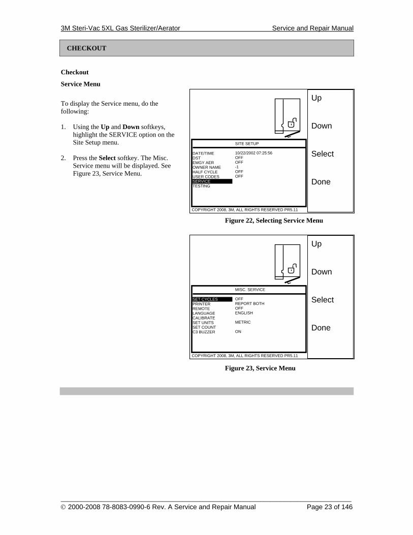
Service Menu
To display the Service menu, do the following: 1. Using the Up and Down softkeys,
highlight the SERVICE option on the Site Setup menu.
2. Press the Select softkey. The Misc.
Service menu will be displayed. See Figure 23, Service Menu.
Figure 22, Selecting Service Menu
Figure 23, Service Menu
3M Steri-Vac 5XL Gas Sterilizer/Aerator Service and Repair Manual
______________________________________________________________________________________ © 2000-2008 78-8083-0990-6 Rev. A Service and Repair Manual Page 24 of 146
Up Down Select Done
BOTH ANALOG DIGITAL REPRINT OPTIONS
COPYRIGHT 2008, 3M, ALL RIGHTS RESERVED PR5.11
PRINTER
CHECKOUT
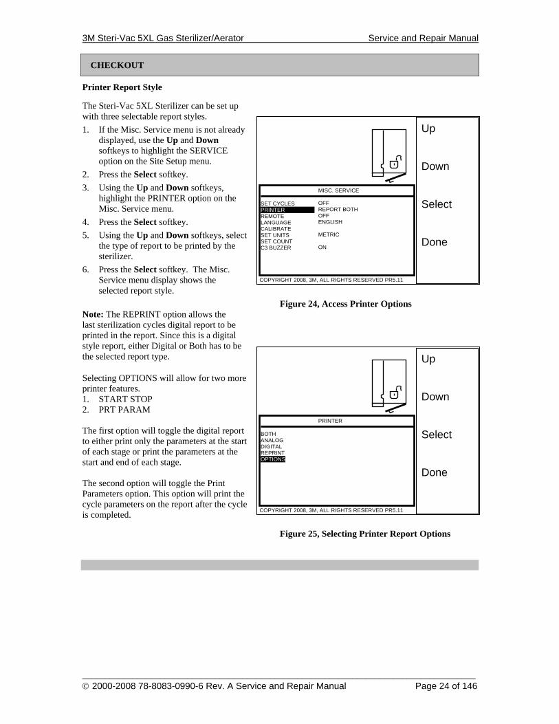
Printer Report Style
The Steri-Vac 5XL Sterilizer can be set up with three selectable report styles. 1. If the Misc. Service menu is not already
displayed, use the Up and Down softkeys to highlight the SERVICE option on the Site Setup menu.
2. Press the Select softkey. 3. Using the Up and Down softkeys,
highlight the PRINTER option on the Misc. Service menu.
4. Press the Select softkey. 5. Using the Up and Down softkeys, select
the type of report to be printed by the sterilizer.
6. Press the Select softkey. The Misc. Service menu display shows the selected report style.
Figure 24, Access Printer Options Note: The REPRINT option allows the last sterilization cycles digital report to be printed in the report. Since this is a digital style report, either Digital or Both has to be the selected report type.
Selecting OPTIONS will allow for two more printer features. 1. START STOP 2. PRT PARAM The first option will toggle the digital report to either print only the parameters at the start of each stage or print the parameters at the start and end of each stage. The second option will toggle the Print Parameters option. This option will print the cycle parameters on the report after the cycle is completed.
Figure 25, Selecting Printer Report Options
Up Down Select Done
SET CYCLES PRINTER REMOTE LANGUAGE CALIBRATE SET UNITS SET COUNT C3 BUZZER
COPYRIGHT 2008, 3M, ALL RIGHTS RESERVED PR5.11
MISC. SERVICE OFF REPORT BOTH OFF ENGLISH METRIC ON
3M Steri-Vac 5XL Gas Sterilizer/Aerator Service and Repair Manual
______________________________________________________________________________________ © 2000-2008 78-8083-0990-6 Rev. A Service and Repair Manual Page 25 of 146
Up Down Select Done
SET CYCLES PRINTER REMOTE LANGUAGE CALIBRATE SET UNITS SET COUNT C3 BUZZER
COPYRIGHT 2008, 3M, ALL RIGHTS RESERVED PR5.11
MISC. SERVICE ON REPORT BOTH OFF ENGLISH METRIC ON
CHECKOUT
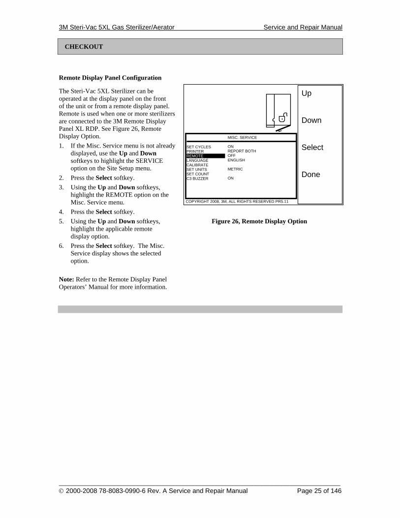
Remote Display Panel Configuration
The Steri-Vac 5XL Sterilizer can be operated at the display panel on the front of the unit or from a remote display panel. Remote is used when one or more sterilizers are connected to the 3M Remote Display Panel XL RDP. See Figure 26, Remote Display Option. 1. If the Misc. Service menu is not already
displayed, use the Up and Down softkeys to highlight the SERVICE option on the Site Setup menu.
2. Press the Select softkey. 3. Using the Up and Down softkeys,
highlight the REMOTE option on the Misc. Service menu.
4. Press the Select softkey. 5. Using the Up and Down softkeys, Figure 26, Remote Display Option
highlight the applicable remote display option.
6. Press the Select softkey. The Misc. Service display shows the selected option.
Note: Refer to the Remote Display Panel Operators’ Manual for more information.
3M Steri-Vac 5XL Gas Sterilizer/Aerator Service and Repair Manual
______________________________________________________________________________________ © 2000-2008 78-8083-0990-6 Rev. A Service and Repair Manual Page 26 of 146
Up Down Select Done
SET CYCLES PRINTER REMOTE LANGUAGE CALIBRATE SET UNITS SET COUNT C3 BUZZER
COPYRIGHT 2008, 3M, ALL RIGHTS RESERVED PR5.11
SITE SETUP ON REPORT BOTH OFF ENGLISH METRIC ON
CHECKOUT
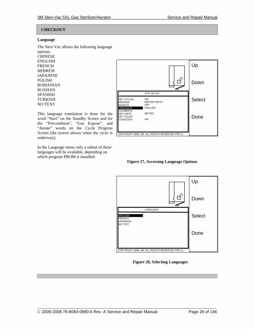
Language
The Steri-Vac allows the following language options: CHINESE ENGLISH FRENCH HEBREW JAPANESE POLISH ROMANIAN RUSSIAN SPANISH TURKISH NO TEXT This language translation is done for the word “Start” on the Standby Screen and for the “Precondition”, “Gas Expose”, and “Aerate” words on the Cycle Progress Screen (the screen shown when the cycle is underway). In the Language menu only a subset of these languages will be available, depending on which program PROM is installed.
Figure 27, Accessing Language Options
Figure 28, Selecting Languages
Up Down Select Done
ENGLISH FRENCH JAPANESE NO TEXT
COPYRIGHT 2008, 3M, ALL RIGHTS RESERVED PR5.11
LANGUAGE
3M Steri-Vac 5XL Gas Sterilizer/Aerator Service and Repair Manual
______________________________________________________________________________________ © 2000-2008 78-8083-0990-6 Rev. A Service and Repair Manual Page 27 of 146
Up Down Select Done
SET CYCLES PRINTER REMOTE LANGUAGE CALIBRATE SET UNITS SET COUNT C3 BUZZER
COPYRIGHT 2008, 3M, ALL RIGHTS RESERVED PR5.11
MISC SERVICE ON REPORT BOTH OFF ENGLISH METRIC ON
Up Down Select Done
SET CYCLES PRINTER REMOTE LANGUAGE CALIBRATE SET UNITS SET COUNT C3 BUZZER
COPYRIGHT 2008, 3M, ALL RIGHTS RESERVED PR5.11
MISC SERVICE ON REPORT BOTH OFF ENGLISH METRIC ON
CHECKOUT
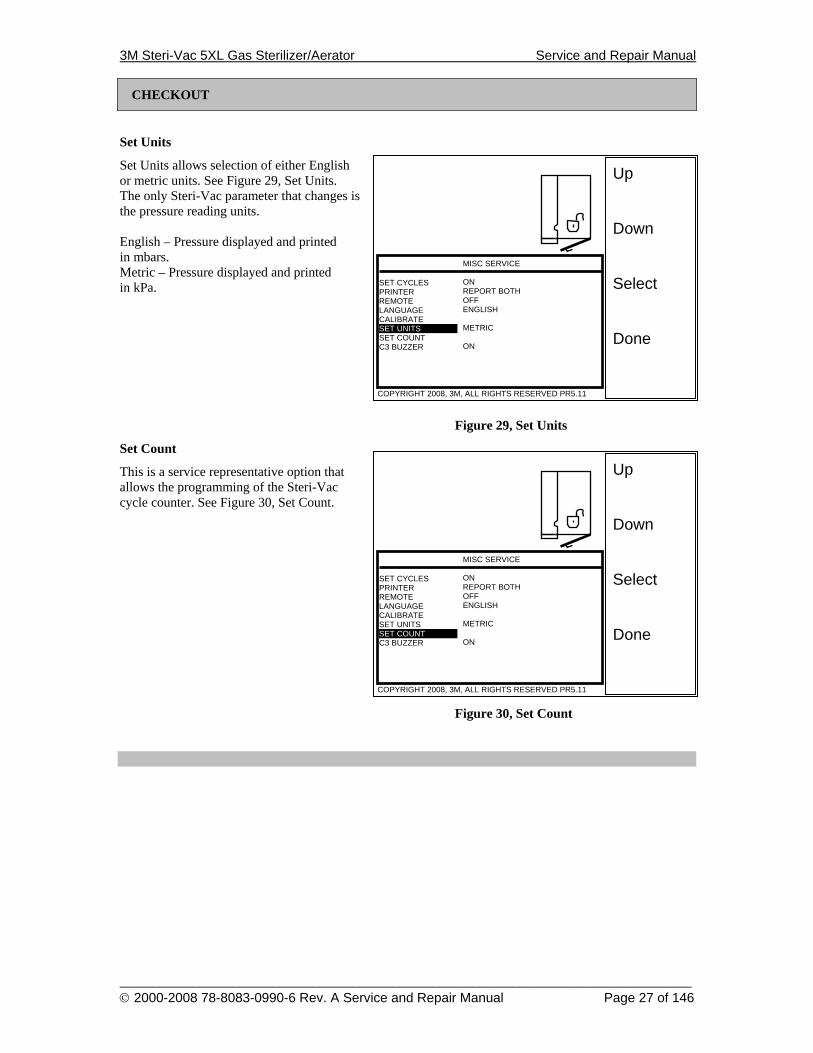
Set Units
Set Units allows selection of either English or metric units. See Figure 29, Set Units. The only Steri-Vac parameter that changes is the pressure reading units. English – Pressure displayed and printed in mbars. Metric – Pressure displayed and printed in kPa.
Figure 29, Set Units
Set Count
This is a service representative option that allows the programming of the Steri-Vac cycle counter. See Figure 30, Set Count.
Figure 30, Set Count
3M Steri-Vac 5XL Gas Sterilizer/Aerator Service and Repair Manual
______________________________________________________________________________________ © 2000-2008 78-8083-0990-6 Rev. A Service and Repair Manual Page 28 of 146
Up Down Select Done
SET CYCLES PRINTER REMOTE LANGUAGE CALIBRATE SET UNITS SET COUNT C3 BUZZER
COPYRIGHT 2008, 3M, ALL RIGHTS RESERVED PR5.11
MISC. SERVICE ON REPORT BOTH OFF ENGLISH METRIC ON
CHECKOUT
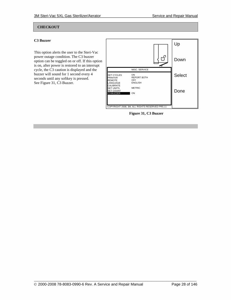
C3 Buzzer
This option alerts the user to the Steri-Vac power outage condition. The C3 buzzer option can be toggled on or off. If this option is on, after power is restored to an interrupt cycle, the C3 caution is displayed and the buzzer will sound for 1 second every 4 seconds until any softkey is pressed. See Figure 31, C3 Buzzer.
Figure 31, C3 Buzzer
3M Steri-Vac 5XL Gas Sterilizer/Aerator Service and Repair Manual
______________________________________________________________________________________ © 2000-2008 78-8083-0990-6 Rev. A Service and Repair Manual Page 29 of 146
Up Down Select Done
SET CYCLES PRINTER REMOTE LANGUAGE CALIBRATE SET UNITS SET COUNT C3 BUZZER
COPYRIGHT 2008, 3M, ALL RIGHTS RESERVED PR5.11
MISC. SERVICE ON REPORT BOTH OFF ENGLISH METRIC ON
1
2
3
4
CHECKOUT
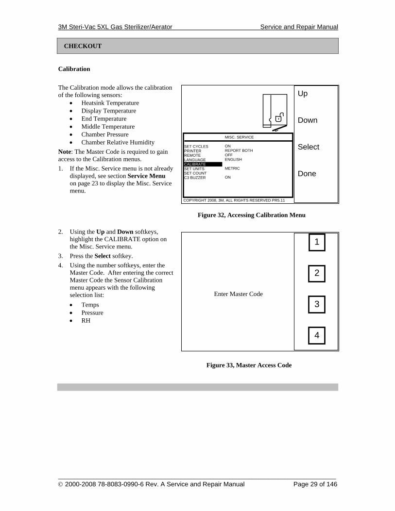
Calibration
The Calibration mode allows the calibration of the following sensors:
• Heatsink Temperature • Display Temperature • End Temperature • Middle Temperature • Chamber Pressure • Chamber Relative Humidity
Note: The Master Code is required to gain access to the Calibration menus. 1. If the Misc. Service menu is not already
displayed, see section Service Menu on page 23 to display the Misc. Service menu.
Figure 32, Accessing Calibration Menu 2. Using the Up and Down softkeys,
highlight the CALIBRATE option on the Misc. Service menu.
3. Press the Select softkey. 4. Using the number softkeys, enter the
Master Code. After entering the correct Master Code the Sensor Calibration menu appears with the following selection list: • Temps • Pressure • RH
Figure 33, Master Access Code
Enter Master Code
3M Steri-Vac 5XL Gas Sterilizer/Aerator Service and Repair Manual
______________________________________________________________________________________ © 2000-2008 78-8083-0990-6 Rev. A Service and Repair Manual Page 30 of 146
Up Down Select Done
TEMPS PRESSURE RH
COPYRIGHT 2008, 3M, ALL RIGHTS RESERVED PR5.11
SENSOR CALIB.
Up Down Select Done
COPYRIGHT 2008, 3M, ALL RIGHTS RESERVED PR5.11
DISPLAY MID END RECORDER AUTO CAL HEATSINK
TEMP CALIBRATION 12/11/02 07:05
CHECKOUT
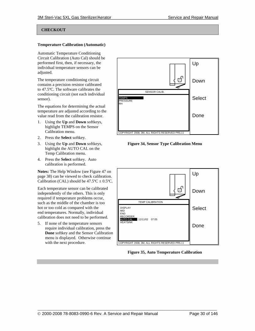
Temperature Calibration (Automatic)
Automatic Temperature Conditioning Circuit Calibration (Auto Cal) should be performed first, then, if necessary, the individual temperature sensors can be adjusted.
The temperature conditioning circuit contains a precision resistor calibrated to 47.5ºC. The software calibrates the conditioning circuit (not each individual sensor).
The equations for determining the actual temperature are adjusted according to the value read from the calibration resistor. 1. Using the Up and Down softkeys,
highlight TEMPS on the Sensor Calibration menu.
2. Press the Select softkey. 3. Using the Up and Down softkeys, Figure 34, Sensor Type Calibration Menu
highlight the AUTO CAL on the Temp Calibration menu.
4. Press the Select softkey. Auto calibration is performed.
Notes: The Help Window (see Figure 47 on page 38) can be viewed to check calibration. Calibration (CAL) should be 47.5ºC ± 0.5ºC.
Each temperature sensor can be calibrated independently of the others. This is only required if temperature problems occur, such as the middle of the chamber is too hot or too cold as compared with the end temperatures. Normally, individual calibration does not need to be performed. 5. If none of the temperature sensors
require individual calibration, press the Done softkey and the Sensor Calibration menu is displayed. Otherwise continue with the next procedure.
Figure 35, Auto Temperature Calibration
3M Steri-Vac 5XL Gas Sterilizer/Aerator Service and Repair Manual
______________________________________________________________________________________ © 2000-2008 78-8083-0990-6 Rev. A Service and Repair Manual Page 31 of 146
CHECKOUT
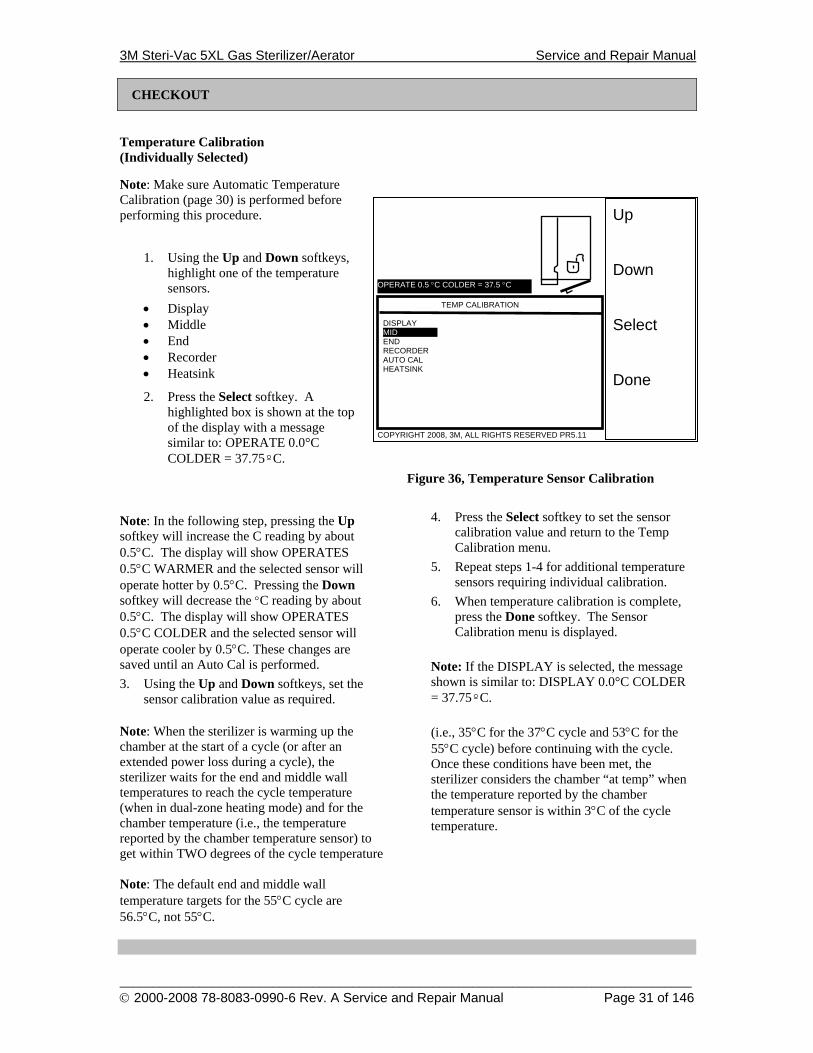
Temperature Calibration (Individually Selected)
Note: Make sure Automatic Temperature Calibration (page 30) is performed before performing this procedure.
1. Using the Up and Down softkeys,
highlight one of the temperature sensors.
• Display • Middle • End • Recorder • Heatsink
2. Press the Select softkey. A highlighted box is shown at the top of the display with a message similar to: OPERATE 0.0°C COLDER = 37.75ºC.
Figure 36, Temperature Sensor Calibration
Note: In the following step, pressing the Up softkey will increase the C reading by about 0.5°C. The display will show OPERATES 0.5°C WARMER and the selected sensor will operate hotter by 0.5°C. Pressing the Down softkey will decrease the °C reading by about 0.5°C. The display will show OPERATES 0.5°C COLDER and the selected sensor will operate cooler by 0.5°C. These changes are saved until an Auto Cal is performed. 3. Using the Up and Down softkeys, set the
sensor calibration value as required.
4. Press the Select softkey to set the sensor calibration value and return to the Temp Calibration menu.
5. Repeat steps 1-4 for additional temperature sensors requiring individual calibration.
6. When temperature calibration is complete, press the Done softkey. The Sensor Calibration menu is displayed.
Note: If the DISPLAY is selected, the message shown is similar to: DISPLAY 0.0°C COLDER = 37.75ºC.
Note: When the sterilizer is warming up the chamber at the start of a cycle (or after an extended power loss during a cycle), the sterilizer waits for the end and middle wall temperatures to reach the cycle temperature (when in dual-zone heating mode) and for the chamber temperature (i.e., the temperature reported by the chamber temperature sensor) to get within TWO degrees of the cycle temperature
(i.e., 35°C for the 37°C cycle and 53°C for the 55°C cycle) before continuing with the cycle. Once these conditions have been met, the sterilizer considers the chamber “at temp” when the temperature reported by the chamber temperature sensor is within 3°C of the cycle temperature.
Note: The default end and middle wall temperature targets for the 55°C cycle are 56.5°C, not 55°C.
Up Down Select Done
COPYRIGHT 2008, 3M, ALL RIGHTS RESERVED PR5.11
DISPLAY MID END RECORDER AUTO CAL HEATSINK
TEMP CALIBRATION
OPERATE 0.5 °C COLDER = 37.5 °C
3M Steri-Vac 5XL Gas Sterilizer/Aerator Service and Repair Manual
______________________________________________________________________________________ © 2000-2008 78-8083-0990-6 Rev. A Service and Repair Manual Page 32 of 146
Up Down Select Done
COPYRIGHT 2008, 3M, ALL RIGHTS RESERVED PR5.11
TEMPS PRESSURE RH
SENSOR CALIB.
CHECKOUT
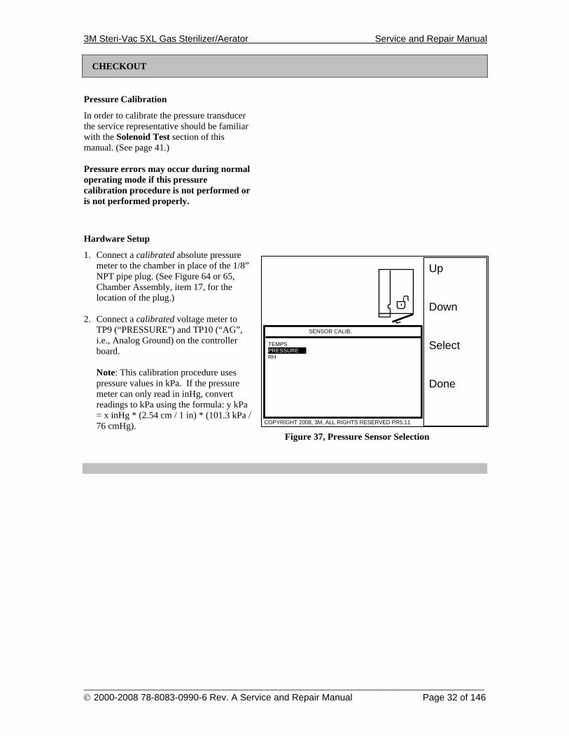
Pressure Calibration
In order to calibrate the pressure transducer the service representative should be familiar with the Solenoid Test section of this manual. (See page 41.) Pressure errors may occur during normal operating mode if this pressure calibration procedure is not performed or is not performed properly.
Hardware Setup
1. Connect a calibrated absolute pressure meter to the chamber in place of the 1/8” NPT pipe plug. (See Figure 64 or 65, Chamber Assembly, item 17, for the location of the plug.)
2. Connect a calibrated voltage meter to
TP9 (“PRESSURE”) and TP10 (“AG”, i.e., Analog Ground) on the controller board.
Note: This calibration procedure uses pressure values in kPa. If the pressure meter can only read in inHg, convert readings to kPa using the formula: y kPa = x inHg * (2.54 cm / 1 in) * (101.3 kPa / 76 cmHg).
Figure 37, Pressure Sensor Selection
3M Steri-Vac 5XL Gas Sterilizer/Aerator Service and Repair Manual
______________________________________________________________________________________ © 2000-2008 78-8083-0990-6 Rev. A Service and Repair Manual Page 33 of 146
CHECKOUT
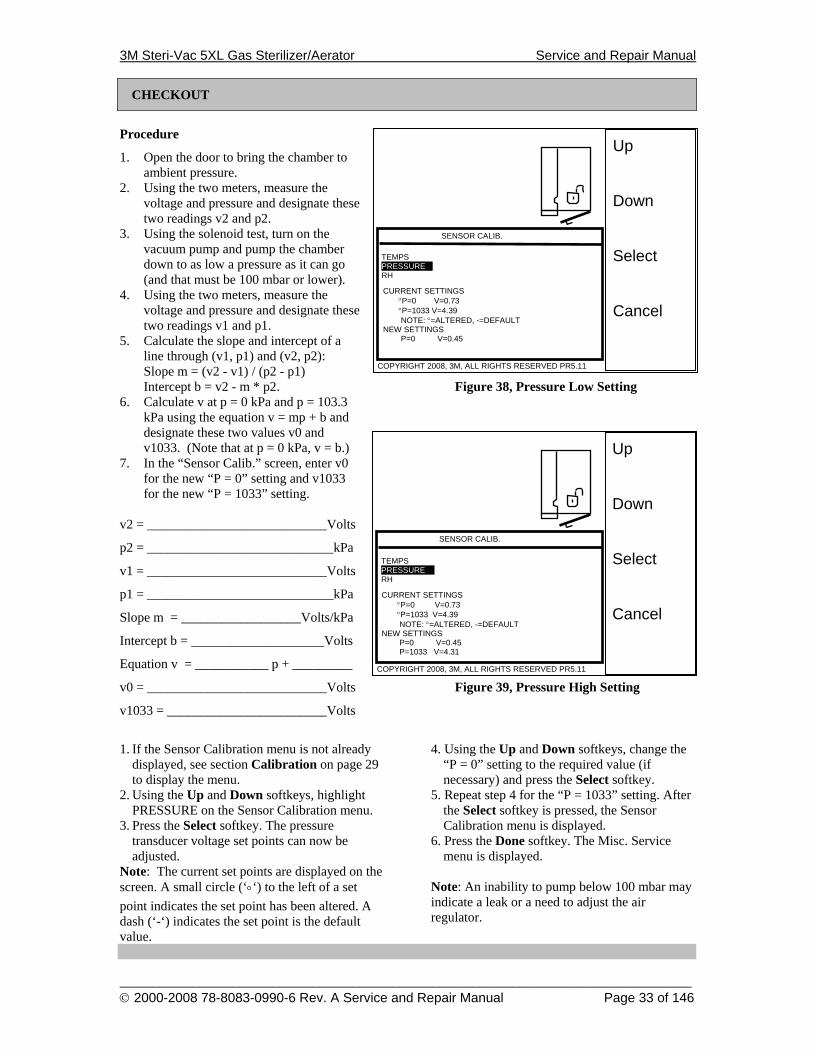
Procedure
1. Open the door to bring the chamber to ambient pressure.
2. Using the two meters, measure the voltage and pressure and designate these two readings v2 and p2.
3. Using the solenoid test, turn on the vacuum pump and pump the chamber down to as low a pressure as it can go (and that must be 100 mbar or lower).
4. Using the two meters, measure the voltage and pressure and designate these two readings v1 and p1.
5. Calculate the slope and intercept of a line through (v1, p1) and (v2, p2): Slope m = (v2 - v1) / (p2 - p1) Intercept b = v2 - m * p2. Figure 38, Pressure Low Setting
6. Calculate v at p = 0 kPa and p = 103.3 kPa using the equation v = mp + b and designate these two values v0 and v1033. (Note that at p = 0 kPa, v = b.)
7. In the “Sensor Calib.” screen, enter v0 for the new “P = 0” setting and v1033 for the new “P = 1033” setting.
v2 = ___________________________Volts
p2 = ____________________________kPa
v1 = ___________________________Volts
p1 = ____________________________kPa
Slope m = __________________Volts/kPa
Intercept b = ____________________Volts
Equation v = ___________ p + _________
v0 = ___________________________Volts Figure 39, Pressure High Setting
v1033 = ________________________Volts
1. If the Sensor Calibration menu is not already displayed, see section Calibration on page 29 to display the menu.
2. Using the Up and Down softkeys, highlight PRESSURE on the Sensor Calibration menu.
3. Press the Select softkey. The pressure transducer voltage set points can now be adjusted.
Note: The current set points are displayed on the screen. A small circle (‘°‘) to the left of a set point indicates the set point has been altered. A dash (‘-‘) indicates the set point is the default value.
4. Using the Up and Down softkeys, change the “P = 0” setting to the required value (if necessary) and press the Select softkey.
5. Repeat step 4 for the “P = 1033” setting. After the Select softkey is pressed, the Sensor Calibration menu is displayed.
6. Press the Done softkey. The Misc. Service menu is displayed.
Note: An inability to pump below 100 mbar may indicate a leak or a need to adjust the air regulator.
Up Down Select Cancel
COPYRIGHT 2008, 3M, ALL RIGHTS RESERVED PR5.11
CURRENT SETTINGS °P=0 V=0.73 °P=1033 V=4.39 NOTE: °=ALTERED, -=DEFAULT NEW SETTINGS P=0 V=0.45
SENSOR CALIB. TEMPS PRESSURE RH
Up Down Select Cancel
COPYRIGHT 2008, 3M, ALL RIGHTS RESERVED PR5.11
CURRENT SETTINGS °P=0 V=0.73 °P=1033 V=4.39 NOTE: °=ALTERED, -=DEFAULT NEW SETTINGS P=0 V=0.45 P=1033 V=4.31
TEMPS PRESSURE RH
SENSOR CALIB.
3M Steri-Vac 5XL Gas Sterilizer/Aerator Service and Repair Manual
______________________________________________________________________________________ © 2000-2008 78-8083-0990-6 Rev. A Service and Repair Manual Page 34 of 146
Up Down Select Cancel
COPYRIGHT 2008, 3M, ALL RIGHTS RESERVED PR5.11
CURRENT SETTINGS ° RH = 0 V = 0.45 ° RH =75.3 V = 2.65 NOTE: °=ALTERED, -=DEAFULT NEW SETTINGS RH = 0 V = 0.45
SENSOR CALIB.
TEMPS PRESSURE RH
CURRENT SETTINGS ° RH = 0 V = 0.45 ° RH=75.3 V = 2.65 NOTE: °=ALTERED, -=DEAFULT NEW SETTINGS RH = 0 V = 0.45 RH = 75.3 V = 2.65
TEMPS PRESSURE RH
Up Down Select Cancel
COPYRIGHT 2008, 3M, ALL RIGHTS RESERVED PR5.11
SENSOR CALIB.
Up Down Select Done
COPYRIGHT 2008, 3M, ALL RIGHTS RESERVED PR5.11
TEMPS PRESSURE RH
SENSOR CALIB.
CHECKOUT
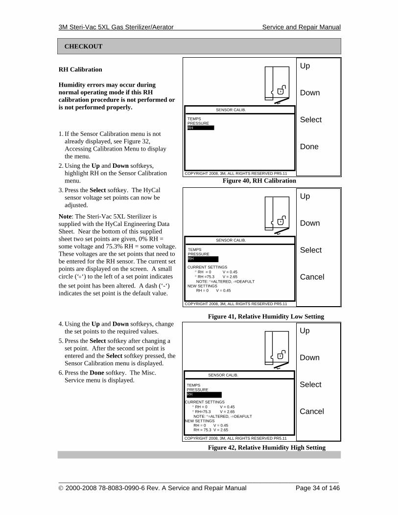
RH Calibration
Humidity errors may occur during normal operating mode if this RH calibration procedure is not performed or is not performed properly.
1. If the Sensor Calibration menu is not already displayed, see Figure 32, Accessing Calibration Menu to display the menu.
2. Using the Up and Down softkeys, highlight RH on the Sensor Calibration menu. Figure 40, RH Calibration
3. Press the Select softkey. The HyCal sensor voltage set points can now be adjusted.
Note: The Steri-Vac 5XL Sterilizer is supplied with the HyCal Engineering Data Sheet. Near the bottom of this supplied sheet two set points are given, 0% RH = some voltage and 75.3% RH = some voltage. These voltages are the set points that need to be entered for the RH sensor. The current set points are displayed on the screen. A small circle (‘°‘) to the left of a set point indicates the set point has been altered. A dash (‘-‘) indicates the set point is the default value.
Figure 41, Relative Humidity Low Setting 4. Using the Up and Down softkeys, change
the set points to the required values. 5. Press the Select softkey after changing a
set point. After the second set point is entered and the Select softkey pressed, the Sensor Calibration menu is displayed.
6. Press the Done softkey. The Misc. Service menu is displayed.
Figure 42, Relative Humidity High Setting
3M Steri-Vac 5XL Gas Sterilizer/Aerator Service and Repair Manual
______________________________________________________________________________________ © 2000-2008 78-8083-0990-6 Rev. A Service and Repair Manual Page 35 of 146
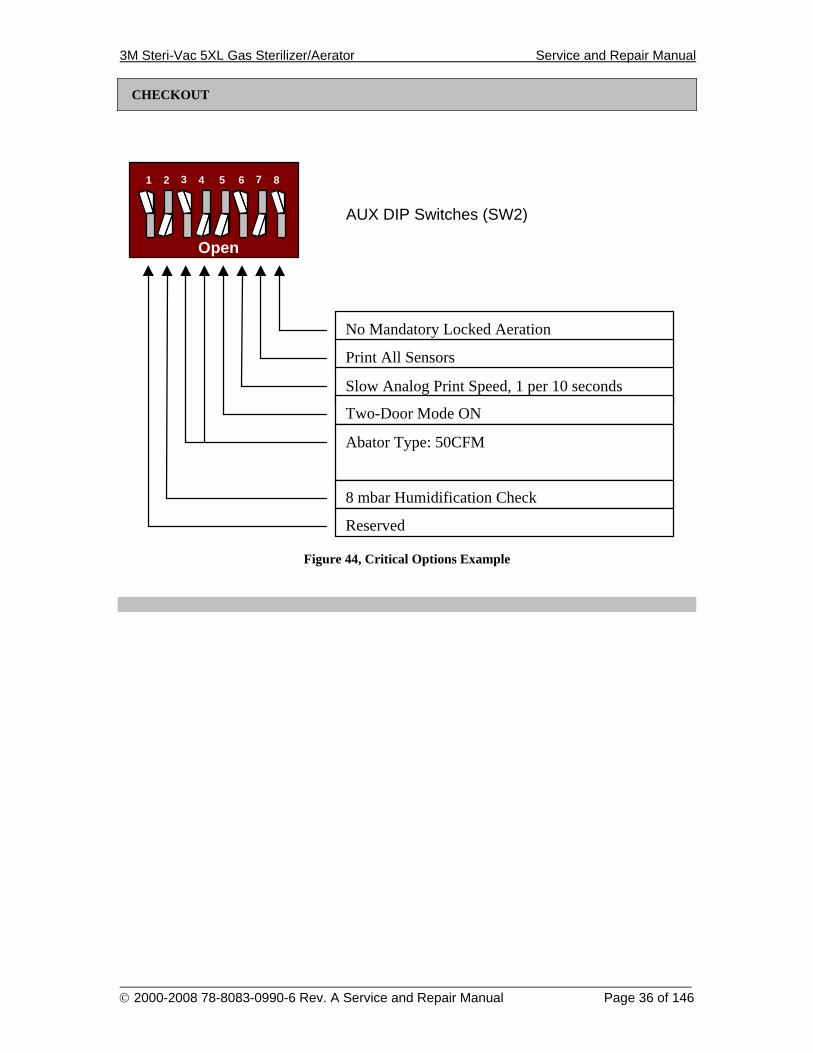
CHECKOUT
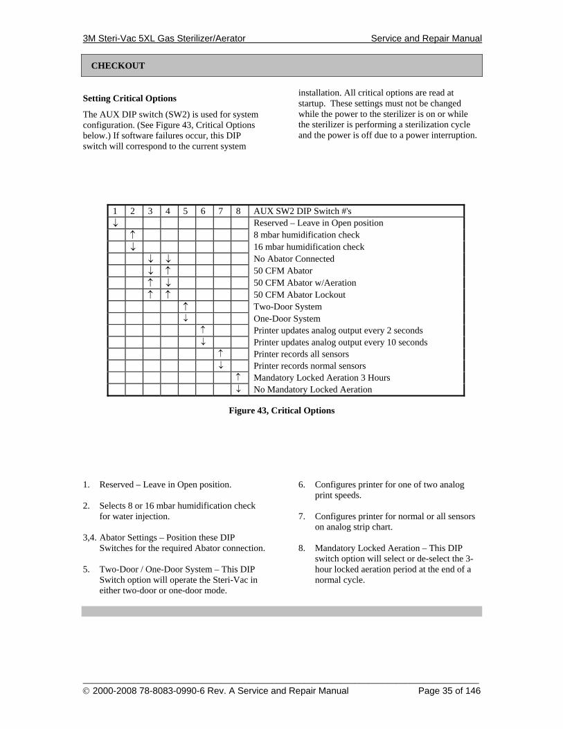
Setting Critical Options
The AUX DIP switch (SW2) is used for system configuration. (See Figure 43, Critical Options below.) If software failures occur, this DIP switch will correspond to the current system
installation. All critical options are read at startup. These settings must not be changed while the power to the sterilizer is on or while the sterilizer is performing a sterilization cycle and the power is off due to a power interruption.
1 2 3 4 5 6 7 8 AUX SW2 DIP Switch #'s ↓ Reserved – Leave in Open position ↑ 8 mbar humidification check ↓ 16 mbar humidification check ↓ ↓ No Abator Connected ↓ ↑ 50 CFM Abator ↑ ↓ 50 CFM Abator w/Aeration ↑ ↑ 50 CFM Abator Lockout ↑ Two-Door System ↓ One-Door System ↑ Printer updates analog output every 2 seconds ↓ Printer updates analog output every 10 seconds ↑ Printer records all sensors ↓ Printer records normal sensors ↑ Mandatory Locked Aeration 3 Hours ↓ No Mandatory Locked Aeration
Figure 43, Critical Options
1. Reserved – Leave in Open position. 2. Selects 8 or 16 mbar humidification check
for water injection. 3,4. Abator Settings – Position these DIP
Switches for the required Abator connection. 5. Two-Door / One-Door System – This DIP
Switch option will operate the Steri-Vac in either two-door or one-door mode.
6. Configures printer for one of two analog print speeds.
7. Configures printer for normal or all sensors
on analog strip chart. 8. Mandatory Locked Aeration – This DIP
switch option will select or de-select the 3-hour locked aeration period at the end of a normal cycle.
3M Steri-Vac 5XL Gas Sterilizer/Aerator Service and Repair Manual
______________________________________________________________________________________ © 2000-2008 78-8083-0990-6 Rev. A Service and Repair Manual Page 36 of 146
CHECKOUT
Open
1 2 3 4
AUX DIP Switches (SW2)
5 6 7 8
No Mandatory Locked Aeration
Print All Sensors
Slow Analog Print Speed, 1 per 10 seconds
Two-Door Mode ON
Abator Type: 50CFM
8 mbar Humidification Check
Reserved
Figure 44, Critical Options Example
3M Steri-Vac 5XL Gas Sterilizer/Aerator Service and Repair Manual
______________________________________________________________________________________ © 2000-2008 78-8083-0990-6 Rev. A Service and Repair Manual Page 37 of 146
TROUBLESHOOTING AND REPAIR
Troubleshooting and Repair
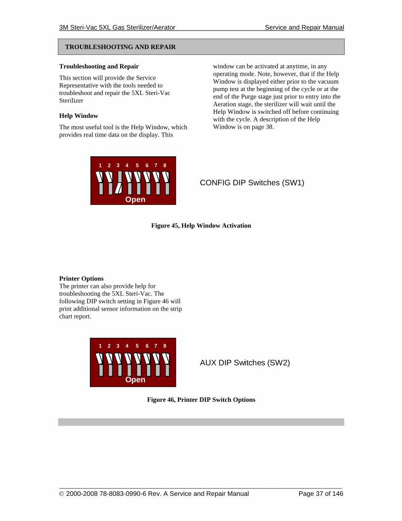
This section will provide the Service Representative with the tools needed to troubleshoot and repair the 5XL Steri-Vac Sterilizer Help Window
The most useful tool is the Help Window, which provides real time data on the display. This
window can be activated at anytime, in any operating mode. Note, however, that if the Help Window is displayed either prior to the vacuum pump test at the beginning of the cycle or at the end of the Purge stage just prior to entry into the Aeration stage, the sterilizer will wait until the Help Window is switched off before continuing with the cycle. A description of the Help Window is on page 38.
Open
1 2 3 4
CONFIG DIP Switches (SW1)
5 6 7 8
Figure 45, Help Window Activation Printer Options The printer can also provide help for troubleshooting the 5XL Steri-Vac. The following DIP switch setting in Figure 46 will print additional sensor information on the strip chart report.
Open
1 2 3 4
AUX DIP Switches (SW2)
5 6 7 8
Figure 46, Printer DIP Switch Options
3M Steri-Vac 5XL Gas Sterilizer/Aerator Service and Repair Manual
______________________________________________________________________________________ © 2000-2008 78-8083-0990-6 Rev. A Service and Repair Manual Page 38 of 146
TROUBLESHOOTING AND REPAIR
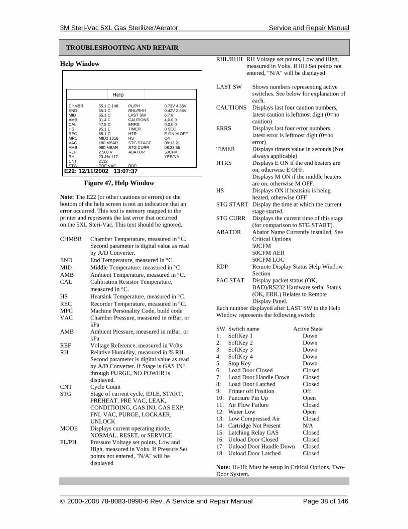
Help Window
Figure 47, Help Window
Note: The E22 (or other cautions or errors) on the bottom of the help screen is not an indication that an error occurred. This text is memory mapped to the printer and represents the last error that occurred on the 5XL Steri-Vac. This text should be ignored. CHMBR Chamber Temperature, measured in °C.
Second parameter is digital value as read by A/D Converter.
END End Temperature, measured in °C. MID Middle Temperature, measured in °C. AMB Ambient Temperature, measured in °C. CAL Calibration Resistor Temperature,
measured in °C. HS Heatsink Temperature, measured in °C. REC Recorder Temperature, measured in °C. MPC Machine Personality Code, build code VAC Chamber Pressure, measured in mBar, or
kPa AMB Ambient Pressure, measured in mBar, or
kPa REF Voltage Reference, measured in Volts RH Relative Humidity, measured in % RH.
Second parameter is digital value as read by A/D Converter. If Stage is GAS INJ through PURGE, NO POWER is displayed.
CNT Cycle Count STG Stage of current cycle, IDLE, START,
PREHEAT, PRE VAC, LEAK, CONDITIOING, GAS INJ, GAS EXP, FNL VAC, PURGE, LOCKAER, UNLOCK
MODE Displays current operating mode, NORMAL, RESET, or SERVICE.
PL/PH Pressure Voltage set points, Low and High, measured in Volts. If Pressure Set points not entered, "N/A" will be displayed
RHL/RHH RH Voltage set points, Low and High, measured in Volts. If RH Set points not entered, "N/A" will be displayed
LAST SW Shows numbers representing active
switches. See below for explanation of each.
CAUTIONS Displays last four caution numbers, latest caution is leftmost digit (0=no caution)
ERRS Displays last four error numbers, latest error is leftmost digit (0=no error)
TIMER Displays timers value in seconds (Not always applicable)
HTRS Displays E ON if the end heaters are on, otherwise E OFF.
Displays M ON if the middle heaters are on, otherwise M OFF.
HS Displays ON if heatsink is being heated, otherwise OFF
STG START Display the time at which the current stage started.
STG CURR Displays the current time of this stage (for comparison to STG START).
ABATOR Abator Name Currently installed, See Critical Options
50CFM 50CFM AER 50CFM LOC RDP Remote Display Status Help Window
Section PAC STAT Display packet status (OK,
BAD)/RS232 Hardware serial Status (OK, ERR.) Relates to Remote Display Panel.
Each number displayed after LAST SW in the Help Window represents the following switch: SW Switch name Active State 1: SoftKey 1 Down 2: SoftKey 2 Down 3: SoftKey 3 Down 4: SoftKey 4 Down 5: Stop Key Down 6: Load Door Closed Closed 7: Load Door Handle Down Closed 8: Load Door Latched Closed 9: Printer off Position Off 10: Puncture Pin Up Open 11: Air Flow Failure Closed 12: Water Low Open 13: Low Compressed Air Closed 14: Cartridge Not Present N/A 15: Latching Relay GAS Closed 16: Unload Door Closed Closed 17: Unload Door Handle Down Closed 18: Unload Door Latched Closed Note: 16-18: Must be setup in Critical Options, Two-Door System.
CHMBR 55.1 C 148 END 55.1 C MID 55.1 C AMB 31.4 C CAL 47.5 C HS 95.1 C REC 55.1 C MPC MID2 1316 VAC 180 MBAR AMB 980 MBAR REF 2.500 V RH 23.4% 117 CNT 2112 STG PRE VAC
E22: 12/11/2002 13:07:37
PL/PH 0.73V 4.36V RHL/RHH 0.42V 2.55V LAST SW 6:7:8: CAUTIONS 4,0,0,0 ERRS 0,0,0,0 TIMER 0 SEC HTR E ON M OFF HS ON STG STAGE 08:13:21 STG CURR 08:33:55 ABATOR 50CFM YES/NA RDP
Help
3M Steri-Vac 5XL Gas Sterilizer/Aerator Service and Repair Manual
______________________________________________________________________________________ © 2000-2008 78-8083-0990-6 Rev. A Service and Repair Manual Page 39 of 146
Up Down Select Done
DATE/TIME DST EMGY AER OWNER NAME HALF CYCLE USER CODES SERVICE TESTING
COPYRIGHT 2008, 3M, ALL RIGHTS RESERVED PR5.11
SITE SETUP 10/22/2002 07:25:56 OFF OFF -1 OFF
Up Down Select Done
SOL TEST H2O ADJUST LEAK TEST
COPYRIGHT 2008 3M, ALL RIGHTS RESERVED PR5.11
TEST MENU
TROUBLESHOOTING AND REPAIR
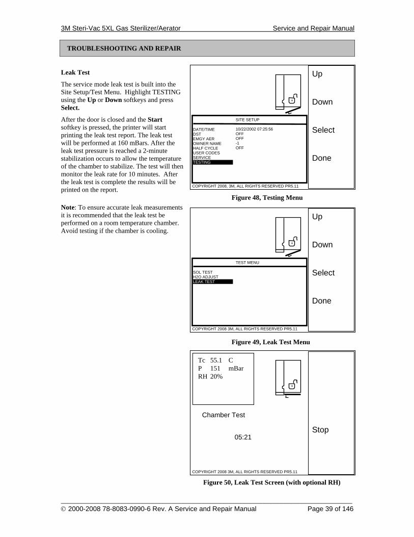
Leak Test
The service mode leak test is built into the Site Setup/Test Menu. Highlight TESTING using the Up or Down softkeys and press Select.
After the door is closed and the Start softkey is pressed, the printer will start printing the leak test report. The leak test will be performed at 160 mBars. After the leak test pressure is reached a 2-minute stabilization occurs to allow the temperature of the chamber to stabilize. The test will then monitor the leak rate for 10 minutes. After the leak test is complete the results will be printed on the report.
Figure 48, Testing Menu Note: To ensure accurate leak measurements it is recommended that the leak test be performed on a room temperature chamber. Avoid testing if the chamber is cooling.
Figure 49, Leak Test Menu
Figure 50, Leak Test Screen (with optional RH)
Stop
COPYRIGHT 2008 3M, ALL RIGHTS RESERVED PR5.11
Chamber Test
Tc 55.1 C P 151 mBar RH 20%
05:21
3M Steri-Vac 5XL Gas Sterilizer/Aerator Service and Repair Manual
______________________________________________________________________________________ © 2000-2008 78-8083-0990-6 Rev. A Service and Repair Manual Page 40 of 146
Up Down Select
SOL TEST H2O ADJUST LEAK TEST
COPYRIGHT 2008 3M, ALL RIGHTS RESERVED PR5.11
TEST MENU
Up Down Select
SOL TEST H2O ADJUST LEAK TEST
COPYRIGHT 2008 3M, ALL RIGHTS RESERVED PR5.11
TEST MENU
Up Down Select Done
DATE/TIME DST EMGY AER OWNER NAME HALF CYCLE USER CODES SERVICE TESTING
COPYRIGHT 2008, 3M, ALL RIGHTS RESERVED PR5.11
SITE SETUP 10/22/2002 07:25:56 OFF OFF -1 OFF
TROUBLESHOOTING AND REPAIR
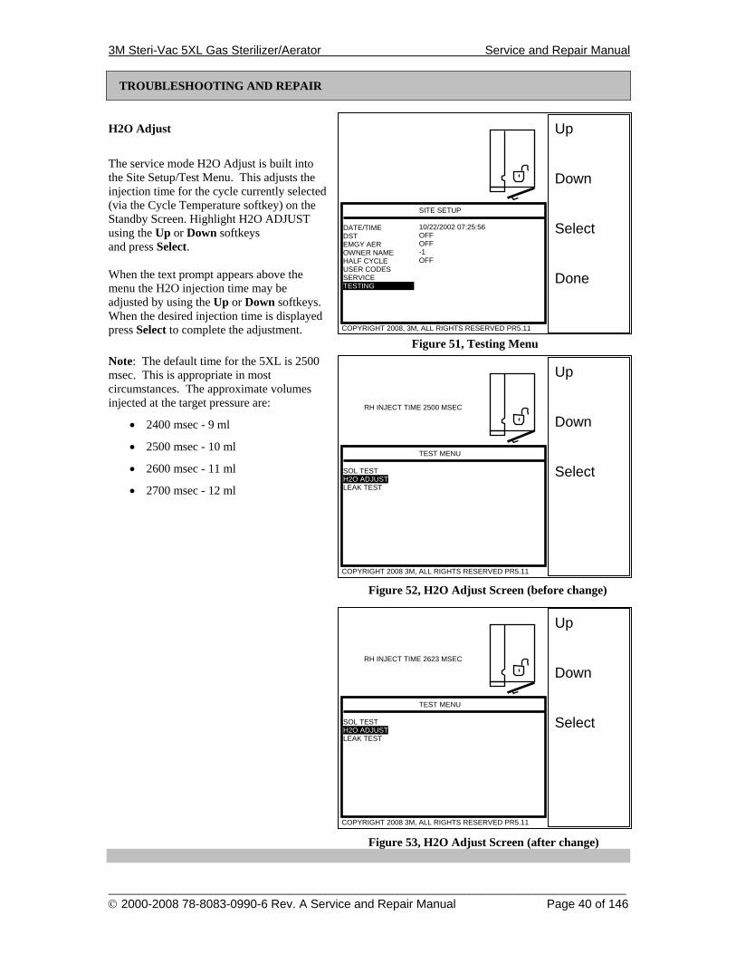
H2O Adjust
The service mode H2O Adjust is built into the Site Setup/Test Menu. This adjusts the injection time for the cycle currently selected (via the Cycle Temperature softkey) on the Standby Screen. Highlight H2O ADJUST using the Up or Down softkeys and press Select. When the text prompt appears above the menu the H2O injection time may be adjusted by using the Up or Down softkeys. When the desired injection time is displayed press Select to complete the adjustment.
Figure 51, Testing Menu Note: The default time for the 5XL is 2500 msec. This is appropriate in most circumstances. The approximate volumes injected at the target pressure are:
• 2400 msec - 9 ml
• 2500 msec - 10 ml
• 2600 msec - 11 ml
• 2700 msec - 12 ml
Figure 52, H2O Adjust Screen (before change)
Figure 53, H2O Adjust Screen (after change)
RH INJECT TIME 2500 MSEC
RH INJECT TIME 2623 MSEC
3M Steri-Vac 5XL Gas Sterilizer/Aerator Service and Repair Manual
______________________________________________________________________________________ © 2000-2008 78-8083-0990-6 Rev. A Service and Repair Manual Page 41 of 146
Up Down Select Done
VACUUM RH H2O VENT DOORS CHMBR HEAT HEATSINK REPORT
COPYRIGHT 2008, 3M, ALL RIGHTS RESERVED PR5.11
SOLENOID TEST ON CLOSED CLOSED CLOSED LOCKED ON ON ON
Tc 55.1 C P 640 mBar RH 20%
Up Down Select Done
SOL TEST H2O ADJUST LEAK TEST
COPYRIGHT 2008 3M, ALL RIGHTS RESERVED PR5.11
SITE SETUP
Up Down Select Done
DATE/TIME DST EMGY AER OWNER NAME HALF CYCLE USER CODES SERVICE TESTING
COPYRIGHT 2008, 3M, ALL RIGHTS RESERVED PR5.11
SITE SETUP 10/22/2002 07:25:56 OFF OFF -1 OFF
TROUBLESHOOTING AND REPAIR
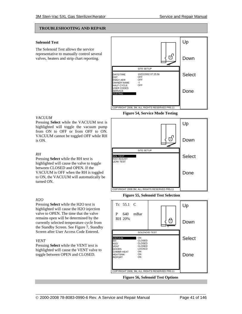
Solenoid Test
The Solenoid Test allows the service representative to manually control several valves, heaters and strip chart reporting.
Figure 54, Service Mode Testing VACUUM Pressing Select while the VACUUM text is highlighted will toggle the vacuum pump from ON to OFF or from OFF to ON. VACUUM cannot be toggled OFF while RH is ON. RH Pressing Select while the RH text is highlighted will cause the valve to toggle between CLOSED and OPEN. If the VACUUM is OFF when the RH is toggled to ON, the VACUUM will automatically be turned ON.
Figure 55, Solenoid Test Selection H2O Pressing Select while the H2O text is highlighted will cause the H2O injection valve to OPEN. The time that the valve remains open will be determined by the currently selected temperature cycle from the Standby Screen. See Figure 7, Standby Screen after User Access Code Entered. VENT Pressing Select while the VENT text is highlighted will cause the VENT valve to toggle between OPEN and CLOSED.
Figure 56, Solenoid Test Options
3M Steri-Vac 5XL Gas Sterilizer/Aerator Service and Repair Manual
______________________________________________________________________________________ © 2000-2008 78-8083-0990-6 Rev. A Service and Repair Manual Page 42 of 146
TROUBLESHOOTING AND REPAIR
Solenoid Test (Continued)
DOORS Pressing Select while the DOORS text is highlighted will cause the door latches to be toggled between LOCKED and UNLOCKED. Note: The DOORS control will allow both doors to be unlocked at the same time for Two-Door systems. CHAMBER HEATERS Pressing Select while the CHMBR HEAT text is highlighted will cause the heaters to toggle between ON and OFF. The target temperature is
determined by the currently selected cycle from the Standby Screen. See Figure 7, Standby Screen after User Access Code Entered. HEATSINK HEATER Pressing Select while the HEATSINK text is highlighted will cause the HEATSINK to toggle between ON and OFF. REPORT Pressing Select while the REPORT text is highlighted will cause the REPORT to toggle between ON and OFF.
3M Steri-Vac 5XL Gas Sterilizer/Aerator Service and Repair Manual
______________________________________________________________________________________ © 2000-2008 78-8083-0990-6 Rev. A Service and Repair Manual Page 43 of 146
TROUBLESHOOTING AND REPAIR
Self-Diagnostics
Overview This outline will summarize the micro controller’s self-diagnostic procedure. Self-diagnostics are performed at startup of the Steri-Vac and before each cycle is started.
Theory of Operation
Steri-Vac Startup Diagnostics - The following are checked every time the power is turned on: Micro Controller Configuration - Checks
MCU configuration and re-programs if necessary.
RAM Test - Reads and writes to each RAM address location.
New RAM Module Detection - Reads designated address for pre-defined value. If value disagrees, Reset Site Setup Information and Reset Cycle Information will automatically be performed.
Printer Detection and Initialization - Detects if printer is installed and if it initialized properly, C8 or C9 may be displayed.
Site Setup Checksum - Detects corrupted memory and software failures. If calculated and stored checksums disagree, E2 is displayed and Reset Site Setup Information is performed automatically.
Cycle Information Checksum - Detects corrupted memory and software failures. If calculated and stored checksums disagree, E1 is displayed and Reset Cycle Information is performed automatically.
Real-time Clock Detection - Detects if Real-time clock is operating properly. If clock fails, E3 will be displayed.
EEPROM Checksum Test - Detects if EEPROM program memory is corrupted. If an error is detected, 3 beeps will be heard and depending on the severity of the error, E3 may be displayed.
Temperature Sensors Connected - Detects if temperature sensors are disconnected.
Relative Humidity Sensor Connected - Detects if Relative Humidity sensor is disconnected.
Pressure Sensor Check - Detects if pressure sensor is connected and pressure within ambient limits.
Pre Cycle - The following are checked every time a cycle is started. Compressed Air Detection - Detects if
compressed air is available and at least 35 psi.
Water Level Detection - Detects if water is in the container.
Temperature Sensors Connected - Detects if temperature sensors are disconnected.
Relative Humidity Sensor Connected - Detects if Relative Humidity sensor is disconnected.
Pressure Sensor Check - Detects if pressure sensor is connected and pressure within ambient limits.
Temperature Range - Verifies temperatures are within normal ranges (5°C and 65°C).
Pressure Range - Verifies pressure is within a normal range (Door open: 600 to 1100 mBar; Door closed: 0 to 1100 mBar).
Analog Circuit Calibration - Checks Calibration resistor. If value exceeds 47.5°C +/- 1°C, C6 is displayed.
Chamber Temperature - Detects if chamber is +3°C warmer than cycle selected.
Abator Error - Detects if abator malfunction during last cycle.
3M Steri-Vac 5XL Gas Sterilizer/Aerator Service and Repair Manual
______________________________________________________________________________________ © 2000-2008 78-8083-0990-6 Rev. A Service and Repair Manual Page 44 of 146
TROUBLESHOOTING AND REPAIR
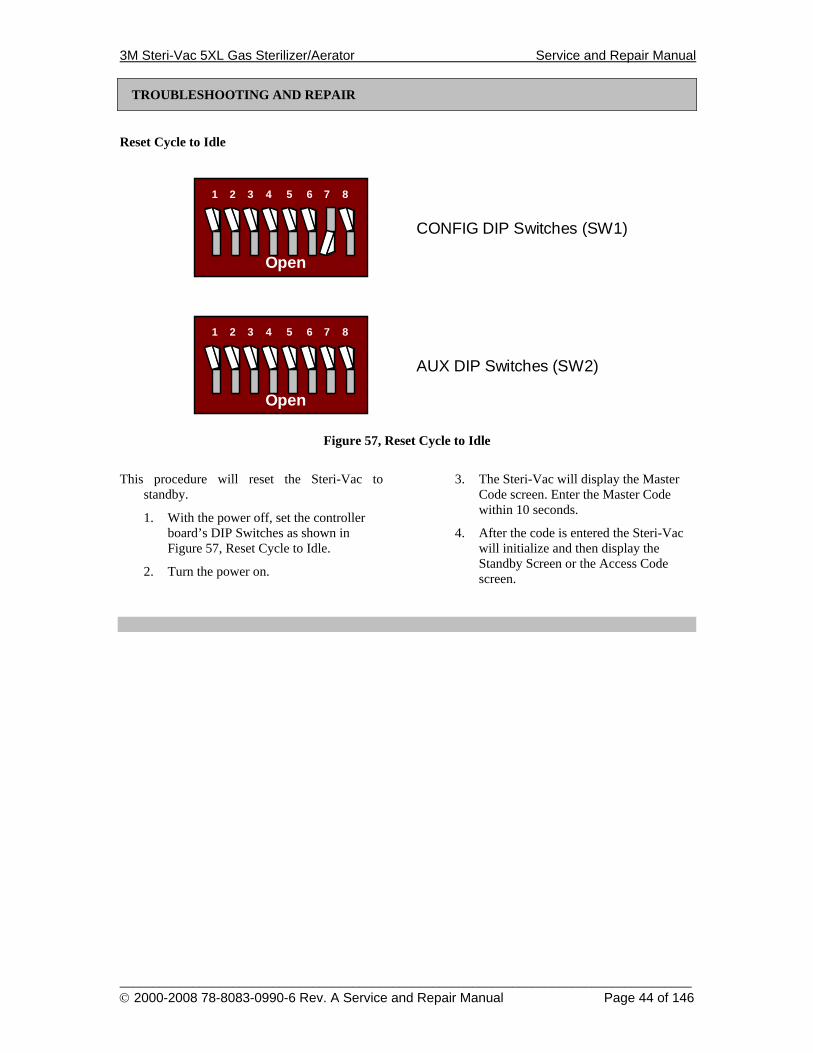
Reset Cycle to Idle
Open
1 2 3 4
CONFIG DIP Switches (SW1)
5 6 7 8
Open
1 2 3 4
AUX DIP Switches (SW2)
5 6 7 8
Figure 57, Reset Cycle to Idle
This procedure will reset the Steri-Vac to standby.
1. With the power off, set the controller board’s DIP Switches as shown in Figure 57, Reset Cycle to Idle.
2. Turn the power on.
3. The Steri-Vac will display the Master Code screen. Enter the Master Code within 10 seconds.
4. After the code is entered the Steri-Vac will initialize and then display the Standby Screen or the Access Code screen.
3M Steri-Vac 5XL Gas Sterilizer/Aerator Service and Repair Manual
______________________________________________________________________________________ © 2000-2008 78-8083-0990-6 Rev. A Service and Repair Manual Page 45 of 146
TROUBLESHOOTING AND REPAIR
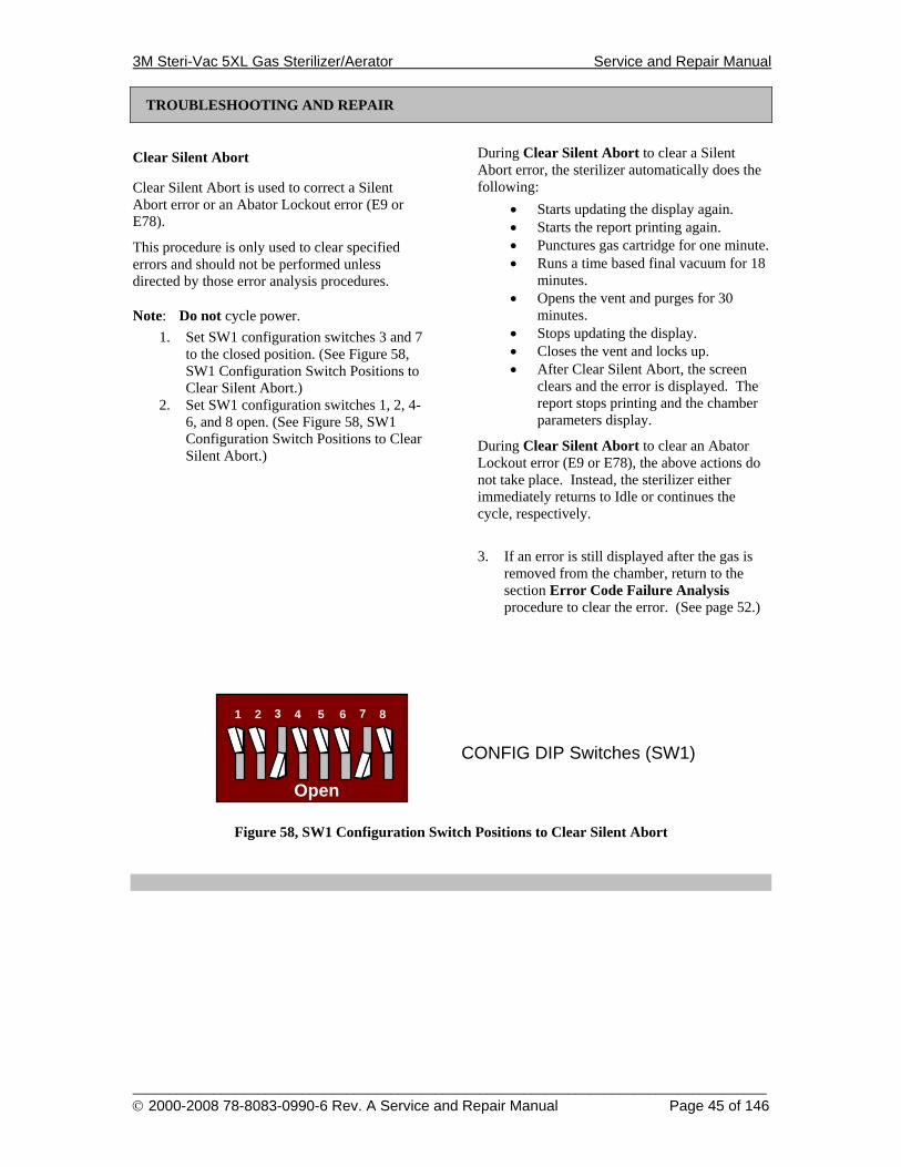
Clear Silent Abort
Clear Silent Abort is used to correct a Silent Abort error or an Abator Lockout error (E9 or E78).
This procedure is only used to clear specified errors and should not be performed unless directed by those error analysis procedures.
Note: Do not cycle power. 1. Set SW1 configuration switches 3 and 7
to the closed position. (See Figure 58, SW1 Configuration Switch Positions to Clear Silent Abort.)
2. Set SW1 configuration switches 1, 2, 4-6, and 8 open. (See Figure 58, SW1 Configuration Switch Positions to Clear Silent Abort.)
During Clear Silent Abort to clear a Silent Abort error, the sterilizer automatically does the following:
• Starts updating the display again. • Starts the report printing again. • Punctures gas cartridge for one minute. • Runs a time based final vacuum for 18
minutes. • Opens the vent and purges for 30
minutes. • Stops updating the display. • Closes the vent and locks up. • After Clear Silent Abort, the screen
clears and the error is displayed. The report stops printing and the chamber parameters display.
During Clear Silent Abort to clear an Abator Lockout error (E9 or E78), the above actions do not take place. Instead, the sterilizer either immediately returns to Idle or continues the cycle, respectively.
3. If an error is still displayed after the gas is
removed from the chamber, return to the section Error Code Failure Analysis procedure to clear the error. (See page 52.)
Open
1 2 3 4
CONFIG DIP Switches (SW1)
5 6 7 8
Figure 58, SW1 Configuration Switch Positions to Clear Silent Abort
3M Steri-Vac 5XL Gas Sterilizer/Aerator Service and Repair Manual
______________________________________________________________________________________ © 2000-2008 78-8083-0990-6 Rev. A Service and Repair Manual Page 46 of 146
TROUBLESHOOTING AND REPAIR
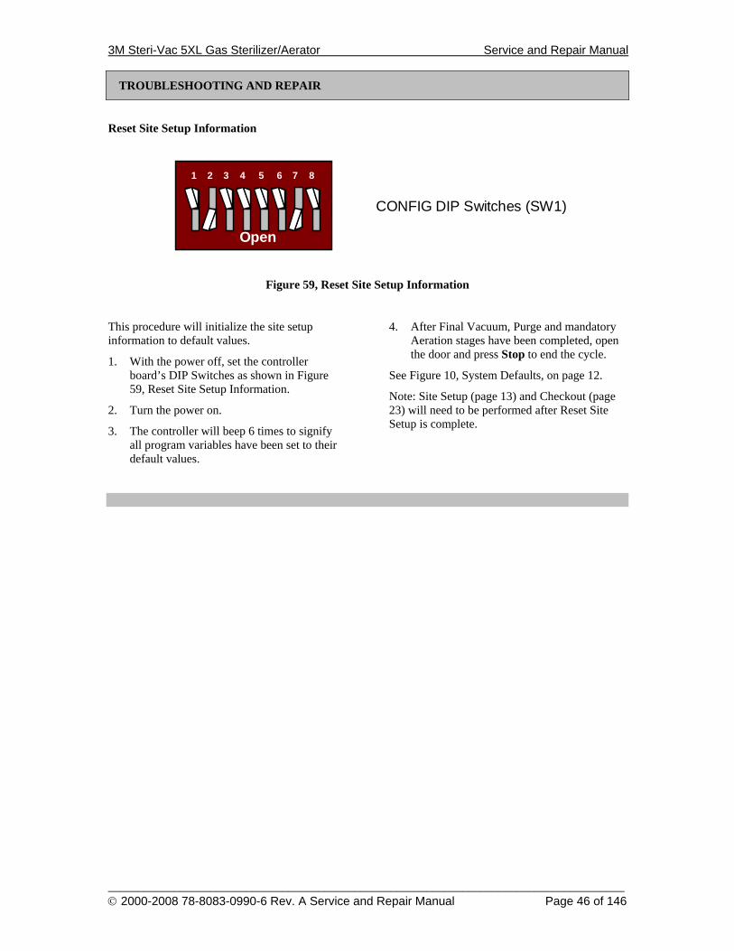
Reset Site Setup Information
Open
1 2 3 4
CONFIG DIP Switches (SW1)
5 6 7 8
Figure 59, Reset Site Setup Information
This procedure will initialize the site setup information to default values.
1. With the power off, set the controller board’s DIP Switches as shown in Figure 59, Reset Site Setup Information.
2. Turn the power on.
3. The controller will beep 6 times to signify all program variables have been set to their default values.
4. After Final Vacuum, Purge and mandatory Aeration stages have been completed, open the door and press Stop to end the cycle.
See Figure 10, System Defaults, on page 12.
Note: Site Setup (page 13) and Checkout (page 23) will need to be performed after Reset Site Setup is complete.
3M Steri-Vac 5XL Gas Sterilizer/Aerator Service and Repair Manual
______________________________________________________________________________________ © 2000-2008 78-8083-0990-6 Rev. A Service and Repair Manual Page 47 of 146
TROUBLESHOOTING AND REPAIR
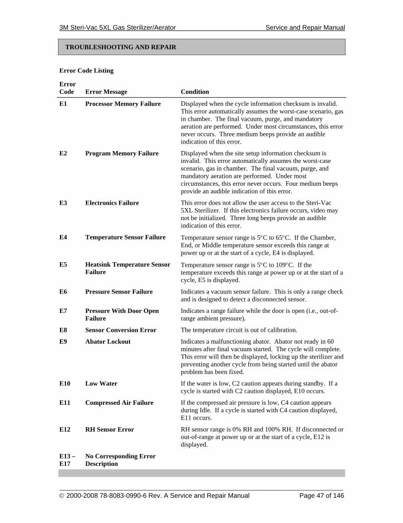
Error Code Listing
Error Code
Error Message
Condition
E1 Processor Memory Failure Displayed when the cycle information checksum is invalid. This error automatically assumes the worst-case scenario, gas in chamber. The final vacuum, purge, and mandatory aeration are performed. Under most circumstances, this error never occurs. Three medium beeps provide an audible indication of this error.
E2 Program Memory Failure Displayed when the site setup information checksum is invalid. This error automatically assumes the worst-case scenario, gas in chamber. The final vacuum, purge, and mandatory aeration are performed. Under most circumstances, this error never occurs. Four medium beeps provide an audible indication of this error.
E3 Electronics Failure This error does not allow the user access to the Steri-Vac 5XL Sterilizer. If this electronics failure occurs, video may not be initialized. Three long beeps provide an audible indication of this error.
E4 Temperature Sensor Failure Temperature sensor range is 5°C to 65°C. If the Chamber, End, or Middle temperature sensor exceeds this range at power up or at the start of a cycle, E4 is displayed.
E5 Heatsink Temperature Sensor Failure
Temperature sensor range is 5°C to 109°C. If the temperature exceeds this range at power up or at the start of a cycle, E5 is displayed.
E6 Pressure Sensor Failure Indicates a vacuum sensor failure. This is only a range check and is designed to detect a disconnected sensor.
E7 Pressure With Door Open Failure
Indicates a range failure while the door is open (i.e., out-of-range ambient pressure).
E8 Sensor Conversion Error The temperature circuit is out of calibration.
E9 Abator Lockout Indicates a malfunctioning abator. Abator not ready in 60 minutes after final vacuum started. The cycle will complete. This error will then be displayed, locking up the sterilizer and preventing another cycle from being started until the abator problem has been fixed.
E10 Low Water If the water is low, C2 caution appears during standby. If a cycle is started with C2 caution displayed, E10 occurs.
E11 Compressed Air Failure If the compressed air pressure is low, C4 caution appears during Idle. If a cycle is started with C4 caution displayed, E11 occurs.
E12 RH Sensor Error RH sensor range is 0% RH and 100% RH. If disconnected or out-of-range at power up or at the start of a cycle, E12 is displayed.
E13 – E17
No Corresponding Error Description
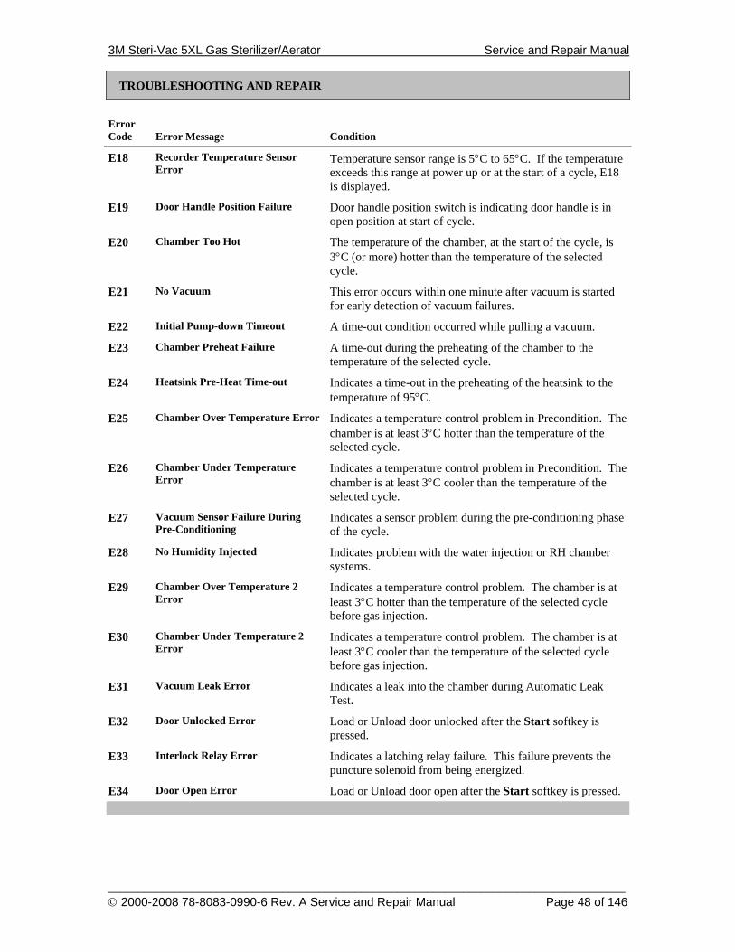
3M Steri-Vac 5XL Gas Sterilizer/Aerator Service and Repair Manual
______________________________________________________________________________________ © 2000-2008 78-8083-0990-6 Rev. A Service and Repair Manual Page 48 of 146
TROUBLESHOOTING AND REPAIR
Error Code
Error Message
Condition
E18 Recorder Temperature Sensor Error
Temperature sensor range is 5°C to 65°C. If the temperature exceeds this range at power up or at the start of a cycle, E18 is displayed.
E19 Door Handle Position Failure Door handle position switch is indicating door handle is in open position at start of cycle.
E20 Chamber Too Hot The temperature of the chamber, at the start of the cycle, is 3°C (or more) hotter than the temperature of the selected cycle.
E21 No Vacuum This error occurs within one minute after vacuum is started for early detection of vacuum failures.
E22 Initial Pump-down Timeout A time-out condition occurred while pulling a vacuum.
E23 Chamber Preheat Failure A time-out during the preheating of the chamber to the temperature of the selected cycle.
E24 Heatsink Pre-Heat Time-out Indicates a time-out in the preheating of the heatsink to the temperature of 95°C.
E25 Chamber Over Temperature Error Indicates a temperature control problem in Precondition. The chamber is at least 3°C hotter than the temperature of the selected cycle.
E26 Chamber Under Temperature Error
Indicates a temperature control problem in Precondition. The chamber is at least 3°C cooler than the temperature of the selected cycle.
E27 Vacuum Sensor Failure During Pre-Conditioning
Indicates a sensor problem during the pre-conditioning phase of the cycle.
E28 No Humidity Injected Indicates problem with the water injection or RH chamber systems.
E29 Chamber Over Temperature 2 Error
Indicates a temperature control problem. The chamber is at least 3°C hotter than the temperature of the selected cycle before gas injection.
E30 Chamber Under Temperature 2 Error
Indicates a temperature control problem. The chamber is at least 3°C cooler than the temperature of the selected cycle before gas injection.
E31 Vacuum Leak Error Indicates a leak into the chamber during Automatic Leak Test.
E32 Door Unlocked Error Load or Unload door unlocked after the Start softkey is pressed.
E33 Interlock Relay Error Indicates a latching relay failure. This failure prevents the puncture solenoid from being energized.
E34 Door Open Error Load or Unload door open after the Start softkey is pressed.
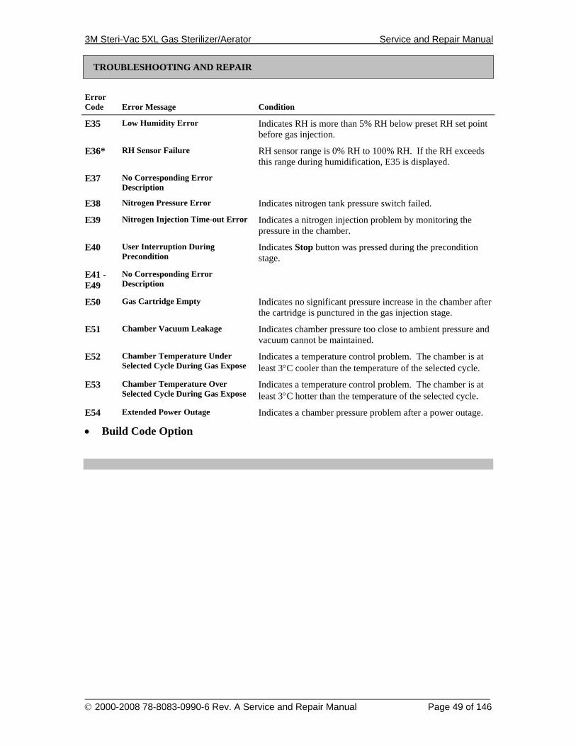
3M Steri-Vac 5XL Gas Sterilizer/Aerator Service and Repair Manual
______________________________________________________________________________________ © 2000-2008 78-8083-0990-6 Rev. A Service and Repair Manual Page 49 of 146
TROUBLESHOOTING AND REPAIR
Error Code
Error Message
Condition
E35 Low Humidity Error Indicates RH is more than 5% RH below preset RH set point before gas injection.
E36* RH Sensor Failure RH sensor range is 0% RH to 100% RH. If the RH exceeds this range during humidification, E35 is displayed.
E37 No Corresponding Error Description
E38 Nitrogen Pressure Error Indicates nitrogen tank pressure switch failed.
E39 Nitrogen Injection Time-out Error Indicates a nitrogen injection problem by monitoring the pressure in the chamber.
E40 User Interruption During Precondition
Indicates Stop button was pressed during the precondition stage.
E41 - E49
No Corresponding Error Description
E50 Gas Cartridge Empty Indicates no significant pressure increase in the chamber after the cartridge is punctured in the gas injection stage.
E51 Chamber Vacuum Leakage Indicates chamber pressure too close to ambient pressure and vacuum cannot be maintained.
E52 Chamber Temperature Under Selected Cycle During Gas Expose
Indicates a temperature control problem. The chamber is at least 3°C cooler than the temperature of the selected cycle.
E53 Chamber Temperature Over Selected Cycle During Gas Expose
Indicates a temperature control problem. The chamber is at least 3°C hotter than the temperature of the selected cycle.
E54 Extended Power Outage Indicates a chamber pressure problem after a power outage.
• Build Code Option
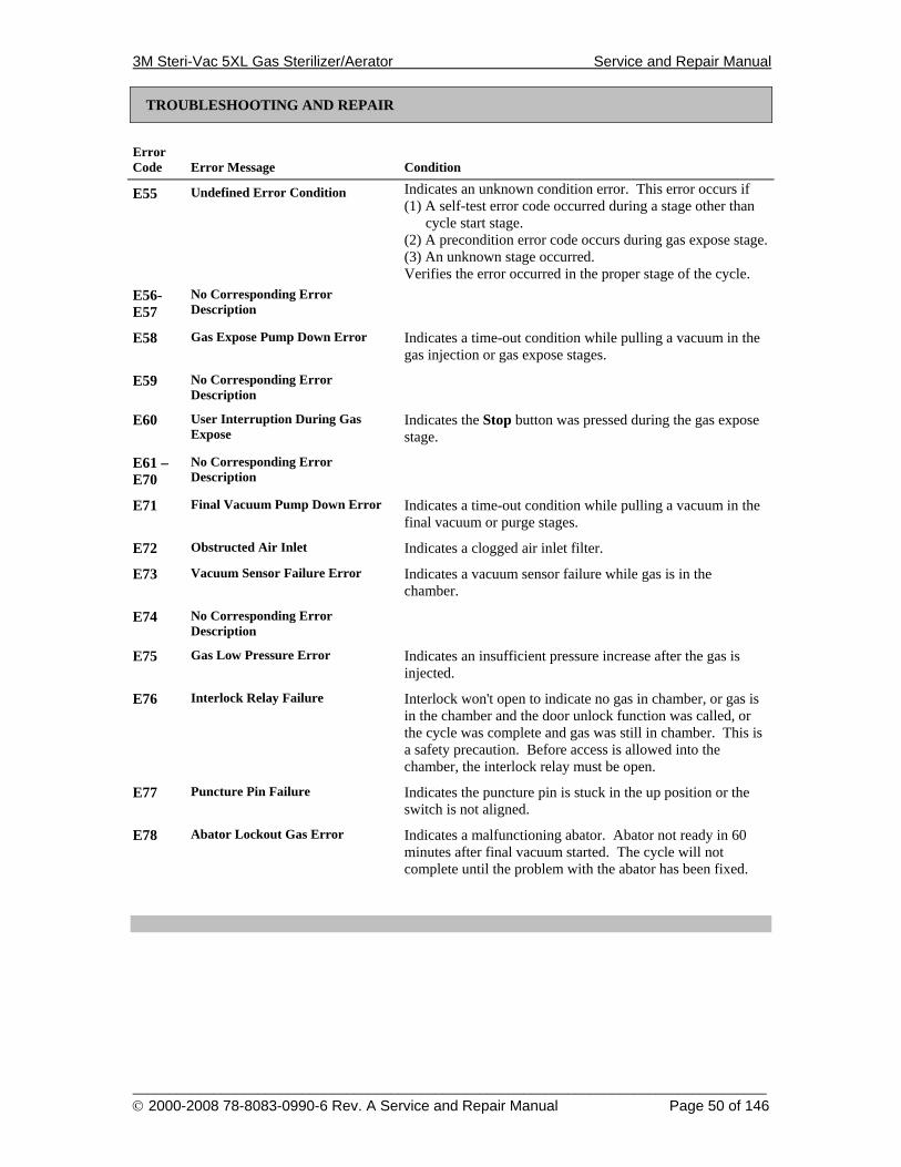
3M Steri-Vac 5XL Gas Sterilizer/Aerator Service and Repair Manual
______________________________________________________________________________________ © 2000-2008 78-8083-0990-6 Rev. A Service and Repair Manual Page 50 of 146
TROUBLESHOOTING AND REPAIR
Error Code
Error Message
Condition
E55 Undefined Error Condition Indicates an unknown condition error. This error occurs if (1) A self-test error code occurred during a stage other than
cycle start stage. (2) A precondition error code occurs during gas expose stage. (3) An unknown stage occurred. Verifies the error occurred in the proper stage of the cycle.
E56-E57
No Corresponding Error Description
E58 Gas Expose Pump Down Error Indicates a time-out condition while pulling a vacuum in the gas injection or gas expose stages.
E59 No Corresponding Error Description
E60 User Interruption During Gas Expose
Indicates the Stop button was pressed during the gas expose stage.
E61 – E70
No Corresponding Error Description
E71 Final Vacuum Pump Down Error Indicates a time-out condition while pulling a vacuum in the final vacuum or purge stages.
E72 Obstructed Air Inlet Indicates a clogged air inlet filter.
E73 Vacuum Sensor Failure Error Indicates a vacuum sensor failure while gas is in the chamber.
E74 No Corresponding Error Description
E75 Gas Low Pressure Error Indicates an insufficient pressure increase after the gas is injected.
E76 Interlock Relay Failure Interlock won't open to indicate no gas in chamber, or gas is in the chamber and the door unlock function was called, or the cycle was complete and gas was still in chamber. This is a safety precaution. Before access is allowed into the chamber, the interlock relay must be open.
E77 Puncture Pin Failure Indicates the puncture pin is stuck in the up position or the switch is not aligned.
E78 Abator Lockout Gas Error Indicates a malfunctioning abator. Abator not ready in 60 minutes after final vacuum started. The cycle will not complete until the problem with the abator has been fixed.
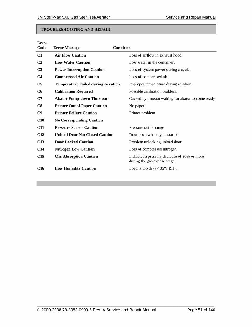
3M Steri-Vac 5XL Gas Sterilizer/Aerator Service and Repair Manual
______________________________________________________________________________________ © 2000-2008 78-8083-0990-6 Rev. A Service and Repair Manual Page 51 of 146
TROUBLESHOOTING AND REPAIR
Error Code
Error Message
Condition
C1 Air Flow Caution Loss of airflow in exhaust hood.
C2 Low Water Caution Low water in the container.
C3 Power Interruption Caution Loss of system power during a cycle.
C4 Compressed Air Caution Loss of compressed air.
C5 Temperature Failed during Aeration Improper temperature during aeration.
C6 Calibration Required Possible calibration problem.
C7 Abator Pump-down Time-out Caused by timeout waiting for abator to come ready
C8 Printer Out of Paper Caution No paper.
C9 Printer Failure Caution Printer problem.
C10 No Corresponding Caution
C11 Pressure Sensor Caution Pressure out of range
C12 Unload Door Not Closed Caution Door open when cycle started
C13 Door Locked Caution Problem unlocking unload door
C14 Nitrogen Low Caution Loss of compressed nitrogen
C15 Gas Absorption Caution Indicates a pressure decrease of 20% or more during the gas expose stage.
C16 Low Humidity Caution Load is too dry (< 35% RH).
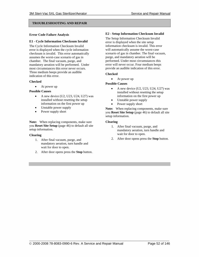
3M Steri-Vac 5XL Gas Sterilizer/Aerator Service and Repair Manual
______________________________________________________________________________________ © 2000-2008 78-8083-0990-6 Rev. A Service and Repair Manual Page 52 of 146
TROUBLESHOOTING AND REPAIR
Error Code Failure Analysis
E1 - Cycle Information Checksum Invalid The Cycle Information Checksum Invalid error is displayed when the cycle information checksum is invalid. This error automatically assumes the worst-case scenario of gas in chamber. The final vacuum, purge, and mandatory aeration will be performed. Under most circumstances this error never occurs. Three medium beeps provide an audible indication of this error.
Checked • At power up
Possible Causes • A new device (U2, U23, U24, U27) was
installed without resetting the setup information on the first power up
• Unstable power supply • Power supply short
Note: When replacing components, make sure you Reset Site Setup (page 46) to default all site setup information.
Clearing 1. After final vacuum, purge, and
mandatory aeration, turn handle and wait for door to open.
2. After door opens press the Stop button.
E2 - Setup Information Checksum Invalid The Setup Information Checksum Invalid error is displayed when the site setup information checksum is invalid. This error will automatically assume the worst-case scenario of gas in chamber. The final vacuum, purge, and mandatory aeration will be performed. Under most circumstances this error will never occur. Four medium beeps provide an audible indication of this error.
Checked • At power up
Possible Causes • A new device (U2, U23, U24, U27) was
installed without resetting the setup information on the first power up
• Unstable power supply • Power supply short
Note: When replacing components, make sure you Reset Site Setup (page 46) to default all site setup information.
Clearing 1. After final vacuum, purge, and
mandatory aeration, turn handle and wait for door to open.
2. After door opens press the Stop button.
3M Steri-Vac 5XL Gas Sterilizer/Aerator Service and Repair Manual
______________________________________________________________________________________ © 2000-2008 78-8083-0990-6 Rev. A Service and Repair Manual Page 53 of 146
TROUBLESHOOTING AND REPAIR
E3 - Electronics Failure The Electronics Failure error will not allow the user access to the sterilizer.
Note: If this error occurs during power up, the video display may not be initialized. Three long beeps provide an audible indication of this error.
If this error occurs during precondition or purge, the sterilizer will lock up until the service representative manually clears the error. See Reset Cycle to Idle (page 44) for clearing procedure.
Checked • At power up • During precondition • During purge
Possible Causes • EPROM checksum failure U23 • RH set point saved failure • RAM failure U24
Clearing The sterilizer stops and ignores all softkeys until power is cycled.
E4 - Temperature Sensor Error The valid range for a temperature sensor (End, Middle or Chamber) is 5°C to 65°C. If the temperature exceeds this range E4 will be displayed.
Checked • At power up • At the start of each cycle
Possible Causes • Disconnected sensor, faulty connection • Chamber too hot
Clearing The sterilizer stops and ignores all softkeys until power is cycled.
3M Steri-Vac 5XL Gas Sterilizer/Aerator Service and Repair Manual
______________________________________________________________________________________ © 2000-2008 78-8083-0990-6 Rev. A Service and Repair Manual Page 54 of 146
TROUBLESHOOTING AND REPAIR
E5 - Heatsink Temperature Sensor The valid range for this temperature sensor is 5°C to 109°C. If the temperature exceeds this range, E5 will be displayed.
Checked • At power up, when in standby • At the start of each cycle
Possible Causes: • Disconnected sensor, faulty connection • Chamber too hot
Clearing The sterilizer stops and ignores all softkeys until power is cycled.
E6 - Pressure Sensor Failure The Vacuum Sensor Failure error indicates a vacuum sensor failure. This is only a range check and is designed to detect a disconnected sensor.
Checked • At power up, when in standby • At the start of each cycle
Possible Causes: • Disconnected sensor, faulty connection
Clearing The sterilizer stops and ignores all softkeys until power is cycled.
3M Steri-Vac 5XL Gas Sterilizer/Aerator Service and Repair Manual
______________________________________________________________________________________ © 2000-2008 78-8083-0990-6 Rev. A Service and Repair Manual Page 55 of 146
TROUBLESHOOTING AND REPAIR
E7 - Pressure Sensor with Door Open Failure The Pressure Sensor with Door Open Failure error indicates a sensor range error while the door is open (i.e., out-of-range ambient pressure).
Checked • At power up, with door open • At the start of each cycle, if door is
open Possible Causes:
• Disconnected sensor, faulty connection • Sensor failure
Clearing The sterilizer stops and ignores all softkeys until power is cycled.
E8 - Sensor Conversion Error The valid range for the controller’s reference voltage is 2.54 V to 2.46 V. (See Help Window on page 37.) If the reference voltage exceeds this range, E8 will be displayed.
Checked • At power up, when in standby • At the start of each cycle
Possible Causes: • Disconnected sensor, faulty connection • Sensor failure
Clearing The sterilizer stops and ignores all softkeys until power is cycled.
3M Steri-Vac 5XL Gas Sterilizer/Aerator Service and Repair Manual
______________________________________________________________________________________ © 2000-2008 78-8083-0990-6 Rev. A Service and Repair Manual Page 56 of 146
TROUBLESHOOTING AND REPAIR
E9 – Abator Lockout The Abator Lockout error indicates the Abator Ready signal was not received within 60 minutes after the final vacuum stage started. This error will be displayed only after the cycle has completed. While the sterilizer was waiting for the abator, the message “Waiting for Abator” will have been displayed on the screen. When the sterilizer continued with the cycle, caution code C7 will have been displayed and printed. This error locks up the sterilizer and prevents the start of another cycle until the problem with the abator is fixed. This error can occur only if the sterilizer has been configured for “50 CFM Abator” or “50 CFM Abator w/Aeration”.
Checked • At the start of final vacuum stage
Possible Causes: • Abator failure • Disconnected or faulty Abator Ready
line Clearing This error locks up the sterilizer after the cycle is complete. Note: Do not cycle power. To clear the error:
1. Fix the problem with the abator. 2. Perform Clear Silent Abort. (See page
45.) 3. Place SW1 configuration switches into
Normal mode. (See Normal Operating Mode on page 9.)
4. The sterilizer will return to Idle.
E10 - Low Water Error If the water is low, caution C2 will appear during Idle. If a cycle is started with this caution displayed, E10 will occur.
Checked • At the start of each cycle
Possible Causes: • Water low • Disconnected sensor, faulty connection • Sensor failure
Clearing 1. Enter the Supervisor Access Code (if
active). 2. Raise the door handle. 3. After door opens, press Stop. 4. Added distilled water as required.
3M Steri-Vac 5XL Gas Sterilizer/Aerator Service and Repair Manual
______________________________________________________________________________________ © 2000-2008 78-8083-0990-6 Rev. A Service and Repair Manual Page 57 of 146
TROUBLESHOOTING AND REPAIR
E11 - Compressed Air Failure The Compressed Air Failure error indicates the compressor air pressure is low. Caution C4 will appear during Idle. If a cycle is started with this caution displayed, E11 will occur.
Checked • At the start of each cycle
Possible Causes: • Compressed air disconnected • Compressed air pressure insufficient • Disconnected sensor, faulty connection
Clearing 1. Enter the Supervisor Access Code
(if active). 2. Raise the door handle. 3. After door opens, press Stop. 4. Fix the compressed air problem before
proceeding.
E12 – RH Sensor Error This error indicates a RH sensor failure. This is only a range check and is designed to detect a disconnected sensor. Requires proper Build Code Option.
Checked • At power up, when in standby • At the start of each cycle
Possible Causes: • Disconnected sensor, faulty connection
Clearing The sterilizer stops and ignores all softkeys until power is cycled.
3M Steri-Vac 5XL Gas Sterilizer/Aerator Service and Repair Manual
______________________________________________________________________________________ © 2000-2008 78-8083-0990-6 Rev. A Service and Repair Manual Page 58 of 146
TROUBLESHOOTING AND REPAIR
E13 – E17 No Corresponding Error Description
E18 – Recorder Temperature Sensor Failure The valid range for this temperature sensor is 5°C to 65°C. If the temperature exceeds this range at either power up or at the start of a cycle, E18 will be displayed. Requires proper Build Code Option.
Checked • At power up • At the start of each cycle
Possible Causes: • Disconnected sensor, faulty connection • Sensor failure
Clearing The sterilizer stops and ignores all softkeys until power is cycled.

3M Steri-Vac 5XL Gas Sterilizer/Aerator Service and Repair Manual
______________________________________________________________________________________ © 2000-2008 78-8083-0990-6 Rev. A Service and Repair Manual Page 59 of 146
TROUBLESHOOTING AND REPAIR
E19 – Door Handle Position Failure The Door Handle Position Failure error indicates the door handle is in the “open” position at the start of the cycle.
Checked • At start of cycle after door is locked
Possible Causes: • Disconnected switch, faulty connection • Switch failure
Clearing
1. Enter the Supervisor Access Code (if active).
2. Raise door handle.
3. After the door opens, press Stop.
E20 - Chamber Too Hot The Chamber Too Hot error indicates the temperature of the chamber is 3°C (or more) hotter than the temperature of the selected cycle.
Checked • At the start of precondition
Possible Causes: • Chamber needs to cool down
Clearing 1. Enter the Supervisor Access Code
(if active). 2. Raise door handle. 3. After the door opens, press Stop. 4. After chamber cools, restart cycle.
3M Steri-Vac 5XL Gas Sterilizer/Aerator Service and Repair Manual
______________________________________________________________________________________ © 2000-2008 78-8083-0990-6 Rev. A Service and Repair Manual Page 60 of 146
TROUBLESHOOTING AND REPAIR
E21 - No Vacuum The No Vacuum error occurs within one minute after vacuum is started for early detection of vacuum failures.
Checked • At the start of precondition (pressure
must decrease 52 mBar in 60 seconds) Possible Causes:
• No compressed air • Chamber leak • Faulty vacuum sensor
Clearing 1. Enter the Supervisor Access Code
(if active). 2. Raise door handle. 3. After door opens, press Stop. 4. Fix the vacuum failure and restart cycle.
E22 - Initial Pump-down Timeout The Initial Pump-down Timeout error indicates a time-out condition occurred while pulling vacuum.
Checked During preconditioning, pressure must decrease to puncture pressure within:
• 20 minutes from the start of air removal • 45 minutes from the start of
preconditioning • 45 minutes from the start of each
nitrogen injection • 15 minutes from the last water injection
and dwell Possible Causes:
• Chamber leak • Faulty vacuum sensor • Defective vacuum pump • Low compressor air pressure • Restricted vent line
Clearing 1. Enter the Supervisor Access Code
(if active). 2. Raise door handle. 3. After door opens, press Stop. 4. Fix the vacuum failure and restart cycle.
3M Steri-Vac 5XL Gas Sterilizer/Aerator Service and Repair Manual
______________________________________________________________________________________ © 2000-2008 78-8083-0990-6 Rev. A Service and Repair Manual Page 61 of 146
TROUBLESHOOTING AND REPAIR
E23 - Chamber Preheat Time-out The Chamber Preheat Time-out error indicates a time-out condition occurred while preheating the chamber to the temperature of the selected cycle.
Checked • During precondition, time-out of 45
minutes Possible Causes:
• Chamber High Limit thermostat • Solid state relay failure, SSR1 or SSR2,
always open circuited • Calibration of end or middle
temperature sensors • Disconnected heater blanket
Clearing 1. Enter the Supervisor Access Code
(if active). 2. Raise door handle. 3. After door opens, press Stop. 4. Fix the heater problem and restart cycle.
E24 - Heatsink Preheat Time-out The Heatsink Preheat Time-out error indicates a time-out condition occurred while preheating the heatsink to the temperature of 95°C.
Checked • During precondition, after initial pump
down, time-out of 45 minutes • During precondition, just prior to
humidification, time-out of 15 minutes Possible Causes:
• Heatsink high limit thermostat opened • Solid state relay failure, SSR3
Clearing 1. Enter the Supervisor Access Code
(if active). 2. Raise door handle. 3. After door opens, press Stop. 4. Fix the heatsink problem and restart
cycle.
3M Steri-Vac 5XL Gas Sterilizer/Aerator Service and Repair Manual
______________________________________________________________________________________ © 2000-2008 78-8083-0990-6 Rev. A Service and Repair Manual Page 62 of 146
TROUBLESHOOTING AND REPAIR
E25 - Chamber Over Temperature The Chamber Over Temperature error indicates a temperature control problem. The chamber temperature is at least 3°C hotter than the temperature of the selected cycle.
Checked • During precondition, humidification
Possible Causes: • Chamber high limit thermostat opened • Solid state relay failure, SSR1 or SSR2
shorted Clearing
1. Enter the Supervisor Access Code (if active).
2. Raise door handle. 3. After door opens, press Stop. 4. Fix the problem and restart cycle.
E26 - Chamber Under Temperature The Chamber Under Temperature error indicates a temperature control problem. The chamber temperature is at least 3°C cooler than the temperature of the selected cycle.
Checked • During precondition, humidification
Possible Causes: • Chamber high limit thermostat opened • Solid state relay failure, SSR1 or SSR2
always open circuited Clearing
1. Enter the Supervisor Access Code (if active).
2. Raise door handle. 3. After door opens, press Stop. 4. Fix the problem and restart cycle.
3M Steri-Vac 5XL Gas Sterilizer/Aerator Service and Repair Manual
______________________________________________________________________________________ © 2000-2008 78-8083-0990-6 Rev. A Service and Repair Manual Page 63 of 146
TROUBLESHOOTING AND REPAIR
E27 – Vacuum Sensor This error indicates a problem with the vacuum sensor during the precondition phase of the cycle.
Checked • During preheat, air removal, leak test
and conditioning stages Possible Causes:
• Disconnected pressure transducer, faulty connection
• Pressure transducer failure • Leak into chamber
Clearing 1. Enter the Supervisor Access Code
(if active). 2. Raise door handle. 3. After door opens, press Stop. 4. Fix the problem and restart cycle.
E28 - No Humidity Injected This indicates a problem with water injection or RH chamber systems. If the preset RH set point cannot be reached in 30 minutes, or if the pressure does not rise by 16 mbar (or 8 mbar, depending upon SW2 switch 2) after the first water injection, or RH < 30% RH at the end of the conditioning stage, then this error occurs.
Checked • During precondition, conditioning
Possible Causes: • Disconnected heatsink temperature
sensor, faulty connection • Heatsink temperature sensor failure • Heatsink heater failure or TCO. • Clogged water line • Leak in RH chamber
Clearing 1. Enter the Supervisor Access Code
(if active). 2. Raise door handle. 3. After door opens, press Stop. 4. Fix the problem and restart cycle.
3M Steri-Vac 5XL Gas Sterilizer/Aerator Service and Repair Manual
______________________________________________________________________________________ © 2000-2008 78-8083-0990-6 Rev. A Service and Repair Manual Page 64 of 146
TROUBLESHOOTING AND REPAIR
E29 - Chamber Over Temperature 2 The Chamber Over Temperature error indicates a temperature control problem. The chamber is at least 3°C hotter than the temperature of the selected cycle before gas injection.
Checked • At the end of precondition,
humidification Possible Causes:
• Chamber high limit thermostat opened • Solid state relay failure, SSR1 or SSR2
shorted Clearing
1. Enter the Supervisor Access Code (if active).
2. Raise door handle. 3. After door opens press Stop. 4. Fix the problem and restart cycle.
E30 - Chamber Under Temperature 2 The Chamber Under Temperature error indicates a temperature control problem. The chamber is at least 3°C cooler than the temperature of the selected cycle.
Checked • At the end of precondition,
humidification Possible Causes:
• Chamber high limit thermostat opened • Solid state relay failure, SSR1 or SSR2
always open circuited Clearing
1. Enter the Supervisor Access Code (if active).
2. Raise door handle. 3. After door opens press Stop. 4. Fix the problem and restart cycle.
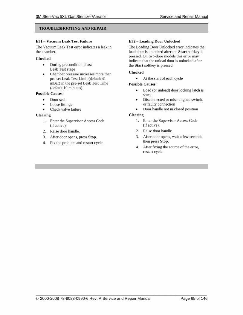
3M Steri-Vac 5XL Gas Sterilizer/Aerator Service and Repair Manual
______________________________________________________________________________________ © 2000-2008 78-8083-0990-6 Rev. A Service and Repair Manual Page 65 of 146
TROUBLESHOOTING AND REPAIR
E31 – Vacuum Leak Test Failure The Vacuum Leak Test error indicates a leak in the chamber.
Checked • During precondition phase,
Leak Test stage • Chamber pressure increases more than
pre-set Leak Test Limit (default 41 mBar) in the pre-set Leak Test Time (default 10 minutes).
Possible Causes: • Door seal • Loose fittings • Check valve failure
Clearing 1. Enter the Supervisor Access Code
(if active). 2. Raise door handle. 3. After door opens, press Stop. 4. Fix the problem and restart cycle.
E32 – Loading Door Unlocked The Loading Door Unlocked error indicates the load door is unlocked after the Start softkey is pressed. On two-door models this error may indicate that the unload door is unlocked after the Start softkey is pressed.
Checked • At the start of each cycle
Possible Causes: • Load (or unload) door locking latch is
stuck • Disconnected or miss-aligned switch,
or faulty connection • Door handle not in closed position
Clearing 1. Enter the Supervisor Access Code
(if active). 2. Raise door handle. 3. After door opens, wait a few seconds
then press Stop. 4. After fixing the source of the error,
restart cycle.
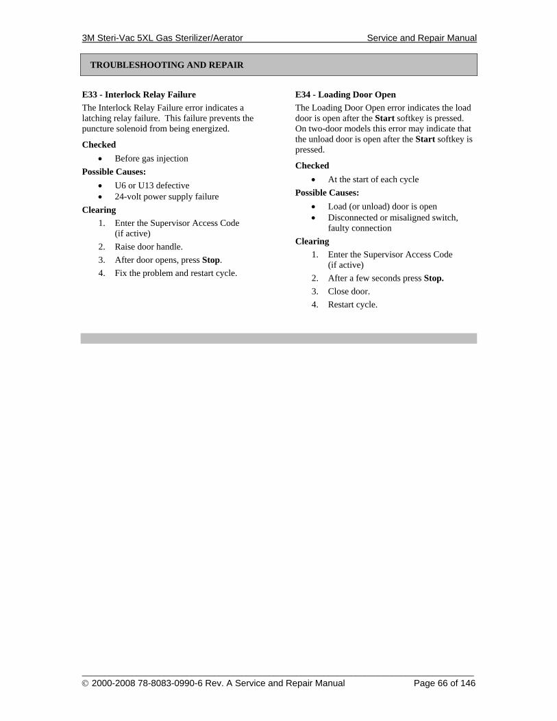
3M Steri-Vac 5XL Gas Sterilizer/Aerator Service and Repair Manual
______________________________________________________________________________________ © 2000-2008 78-8083-0990-6 Rev. A Service and Repair Manual Page 66 of 146
TROUBLESHOOTING AND REPAIR
E33 - Interlock Relay Failure The Interlock Relay Failure error indicates a latching relay failure. This failure prevents the puncture solenoid from being energized.
Checked • Before gas injection
Possible Causes: • U6 or U13 defective • 24-volt power supply failure
Clearing 1. Enter the Supervisor Access Code
(if active) 2. Raise door handle. 3. After door opens, press Stop. 4. Fix the problem and restart cycle.
E34 - Loading Door Open The Loading Door Open error indicates the load door is open after the Start softkey is pressed. On two-door models this error may indicate that the unload door is open after the Start softkey is pressed.
Checked • At the start of each cycle
Possible Causes: • Load (or unload) door is open • Disconnected or misaligned switch,
faulty connection Clearing
1. Enter the Supervisor Access Code (if active)
2. After a few seconds press Stop. 3. Close door. 4. Restart cycle.

3M Steri-Vac 5XL Gas Sterilizer/Aerator Service and Repair Manual
______________________________________________________________________________________ © 2000-2008 78-8083-0990-6 Rev. A Service and Repair Manual Page 67 of 146
TROUBLESHOOTING AND REPAIR
E35 - Low Humidity The Low Humidity error indicates RH is more than 5% RH below preset RH set point.
Checked • During precondition, conditioning
Possible Causes: • Water low • RH chamber leak • RH sensor disconnected, faulty
connection, or sensor failure • Water solenoid failure
Clearing 1. Enter the Supervisor Access Code
(if active) 2. Raise door handle. 3. After door opens, press Stop. 4. Fix the problem and restart cycle.
E36 – RH Sensor Failure Error This indicates a problem with the RH sensor. This error occurs if the measured RH < 0% RH or RH > 100% RH after humidification of the chamber.
Checked • During precondition, conditioning
Possible Causes: • Disconnected heatsink temperature
sensor, faulty connection • RH Sensor Disconnected • Leak in RH chamber
Clearing 1. Enter the Supervisor Access Code
(if active). 2. Raise door handle. 3. After door opens, press Stop.
4. Fix the problem and restart cycle.

3M Steri-Vac 5XL Gas Sterilizer/Aerator Service and Repair Manual
______________________________________________________________________________________ © 2000-2008 78-8083-0990-6 Rev. A Service and Repair Manual Page 68 of 146
TROUBLESHOOTING AND REPAIR
E37 - No Corresponding Error Description E38 - Nitrogen Pressure
The Nitrogen pressure is low. The Nitrogen option must be activated using the proper Build Code Option for this error to occur.
Checked • During precondition
Possible Causes: • Nitrogen tank is empty • Faulty pressure transducer or switch
Clearing 1. Enter the Supervisor Access Code
(if active). 2. Raise door handle. 3. After door opens, press Stop. 4. Fix the problem and restart cycle.
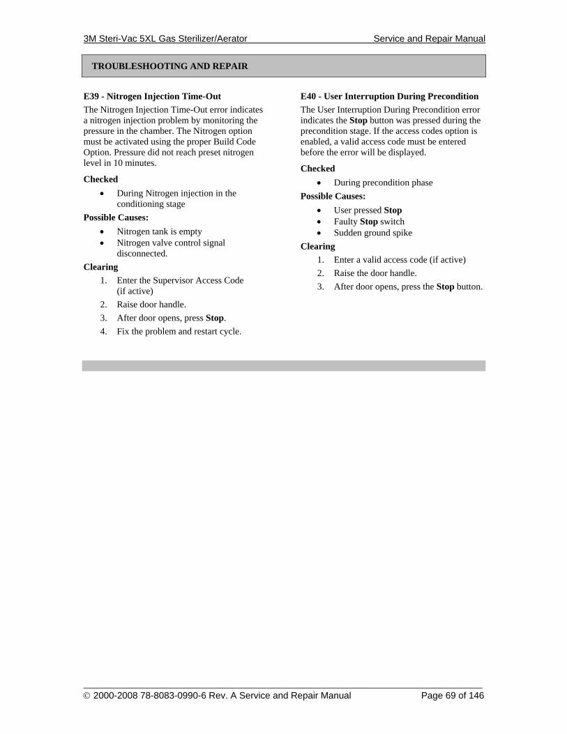
3M Steri-Vac 5XL Gas Sterilizer/Aerator Service and Repair Manual
______________________________________________________________________________________ © 2000-2008 78-8083-0990-6 Rev. A Service and Repair Manual Page 69 of 146
TROUBLESHOOTING AND REPAIR
E39 - Nitrogen Injection Time-Out The Nitrogen Injection Time-Out error indicates a nitrogen injection problem by monitoring the pressure in the chamber. The Nitrogen option must be activated using the proper Build Code Option. Pressure did not reach preset nitrogen level in 10 minutes.
Checked • During Nitrogen injection in the
conditioning stage Possible Causes:
• Nitrogen tank is empty • Nitrogen valve control signal
disconnected. Clearing
1. Enter the Supervisor Access Code (if active)
2. Raise door handle. 3. After door opens, press Stop. 4. Fix the problem and restart cycle.
E40 - User Interruption During Precondition The User Interruption During Precondition error indicates the Stop button was pressed during the precondition stage. If the access codes option is enabled, a valid access code must be entered before the error will be displayed.
Checked • During precondition phase
Possible Causes: • User pressed Stop • Faulty Stop switch • Sudden ground spike
Clearing 1. Enter a valid access code (if active) 2. Raise the door handle. 3. After door opens, press the Stop button.
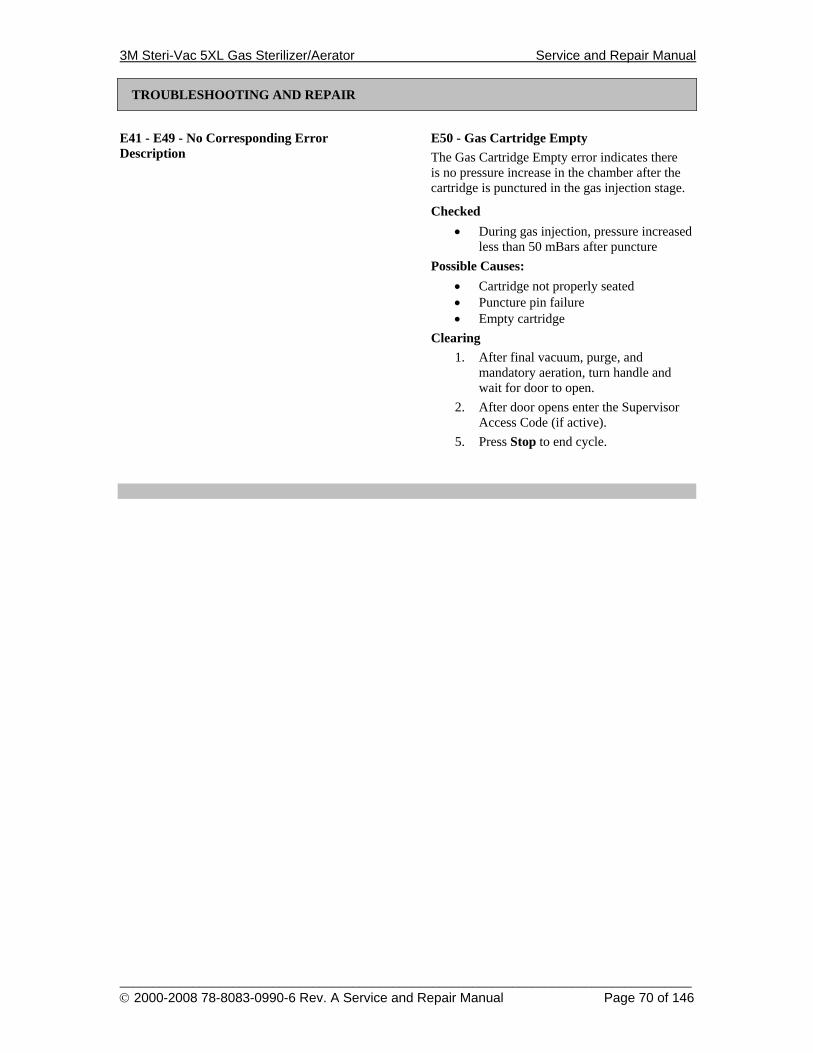
3M Steri-Vac 5XL Gas Sterilizer/Aerator Service and Repair Manual
______________________________________________________________________________________ © 2000-2008 78-8083-0990-6 Rev. A Service and Repair Manual Page 70 of 146
TROUBLESHOOTING AND REPAIR
E41 - E49 - No Corresponding Error Description
E50 - Gas Cartridge Empty The Gas Cartridge Empty error indicates there is no pressure increase in the chamber after the cartridge is punctured in the gas injection stage.
Checked • During gas injection, pressure increased
less than 50 mBars after puncture Possible Causes:
• Cartridge not properly seated • Puncture pin failure • Empty cartridge
Clearing 1. After final vacuum, purge, and
mandatory aeration, turn handle and wait for door to open.
2. After door opens enter the Supervisor Access Code (if active).
5. Press Stop to end cycle.
3M Steri-Vac 5XL Gas Sterilizer/Aerator Service and Repair Manual
______________________________________________________________________________________ © 2000-2008 78-8083-0990-6 Rev. A Service and Repair Manual Page 71 of 146
TROUBLESHOOTING AND REPAIR
E51 - Chamber Vacuum Leakage The Chamber Vacuum Leakage error occurs when the chamber pressure approaches within 80 mBar of ambient pressure three times.
Checked • During the gas injection and gas
exposure stages Possible Causes:
• Door seal • Loose fittings
Clearing 1. After final vacuum, purge, and
mandatory aeration, turn handle and wait for door to open.
2. After door opens enter the Supervisor Access Code (if active).
3. Press Stop to end cycle.
E52 - Chamber Temperature Under Selected Cycle During Gas Expose The Chamber Temperature Under Selected Cycle During Gas Expose error indicates a temperature control problem. The chamber is at least 3°C cooler than the temperature of the selected cycle.
Checked • During gas injection and gas exposure
stages Possible Causes:
• Chamber High Limit thermostat • Solid state relay failure, SSR1 or SSR2 • Improper calibration of end and/or
middle temperature sensors Clearing
1. After final vacuum, purge, and mandatory aeration, turn handle and wait for door to open.
2. After door opens enter the Supervisor Access Code (if active).
3. Press Stop to end cycle.
3M Steri-Vac 5XL Gas Sterilizer/Aerator Service and Repair Manual
______________________________________________________________________________________ © 2000-2008 78-8083-0990-6 Rev. A Service and Repair Manual Page 72 of 146
TROUBLESHOOTING AND REPAIR
E53 - Chamber Temperature Over Selected Cycle During Gas Expose The Chamber Temperature Over Selected Cycle During Gas Expose error indicates a temperature control problem. The chamber is at least 3°C hotter than the temperature of the selected cycle.
Checked • During gas injection and gas exposure
stages Possible Causes:
• Solid state relay failure, SSR1 or SSR2 • Improper calibration of end and/or
middle temperature sensors Clearing
1. After final vacuum, purge, and mandatory aeration, turn handle and wait for door to open.
2. After door opens enter the Supervisor Access Code (if active).
3. Press Stop to end cycle.
E54 - Extended Power Outage The Extended Power Outage error indicates a chamber pressure problem after a power outage. The pressure inside the chamber is too close to ambient.
Checked • During recovery of gas injection or gas
exposure stages, after a power outage Possible Causes:
• Air leak into chamber Clearing
1. After final vacuum, purge, and mandatory aeration, turn handle and wait for door to open.
2. After door opens enter the Supervisor Access Code (if active).
3. Press Stop to end cycle.
3M Steri-Vac 5XL Gas Sterilizer/Aerator Service and Repair Manual
______________________________________________________________________________________ © 2000-2008 78-8083-0990-6 Rev. A Service and Repair Manual Page 73 of 146
TROUBLESHOOTING AND REPAIR
E55 - Undefined Error Condition The Undefined Error Condition error is an unknown error condition and occurs if:
• A self test error code occurred during a stage other than cycle start stage
• A precondition error code occurs during gas expose stage
• An unknown stage occurred This verifies the error occurred in the proper stage of the cycle.
Checked • Error manager, after another error
occurs Possible Causes:
• See E2 and E3 Clearing
1. After final vacuum, purge, and mandatory aeration, turn handle and wait for door to open.
2. After door opens enter the Supervisor Access Code (if active).
3. Press Stop to end cycle.
E56 – E57 No Corresponding Error Description

3M Steri-Vac 5XL Gas Sterilizer/Aerator Service and Repair Manual
______________________________________________________________________________________ © 2000-2008 78-8083-0990-6 Rev. A Service and Repair Manual Page 74 of 146
TROUBLESHOOTING AND REPAIR
E58 - Gas Expose Pump Down Error The Gas Expose Pump Down error indicates a time-out condition occurred while pulling vacuum in the gas injection or gas expose stages. If the chamber pressure rises to within 80 mbar of ambient, the sterilizer will turn on the vacuum pump to lower the pressure. If the pressure cannot be brought 180 mbar below ambient within two minutes, an E58 will occur.
Checked • During gas injection • During gas expose
Possible Causes: • Compressed air disconnected • Compressed air pressure insufficient • Disconnected pressure transducer or
faulty connection • Vacuum pump failure • Restricted vent line • Air leak into chamber
Clearing 1. After final vacuum, purge, and
mandatory aeration, turn handle and wait for door to open.
2. After door opens enter the Supervisor Access Code (if active).
3. Press Stop to end cycle.
E59 - No Corresponding Error Description

3M Steri-Vac 5XL Gas Sterilizer/Aerator Service and Repair Manual
______________________________________________________________________________________ © 2000-2008 78-8083-0990-6 Rev. A Service and Repair Manual Page 75 of 146
TROUBLESHOOTING AND REPAIR
E60 - User Interruption During Gas Expose The User Interruption During Gas Expose error indicates the Stop button was pressed during the gas injection or gas expose stage and the supervisor’s access code was entered.
Checked • During gas injection or gas exposure
stages Possible Causes:
• User pressed Stop • Stop switch failure • Sudden ground spike
Clearing 1. After final vacuum, purge, and
mandatory aeration, turn handle and wait for door to open.
2. After door opens enter the Supervisor Access Code (if active).
3. Press Stop to end cycle.
E61 - E70 - No Corresponding Error Description
3M Steri-Vac 5XL Gas Sterilizer/Aerator Service and Repair Manual
______________________________________________________________________________________ © 2000-2008 78-8083-0990-6 Rev. A Service and Repair Manual Page 76 of 146
TROUBLESHOOTING AND REPAIR
E71 - Final Vacuum Pump Down The Final Vacuum Pump Down error indicates a time-out condition occurred while pulling vacuum in the final vacuum or purge stages. If an abator is installed a time-out occurs if the pressure does not reach 250 mBars within 60 minutes, and does not reach 160 mBars within an additional 30 minutes. If an abator is not installed, a time-out will occur if the pressure does not reach 160 mBars within 90 minutes. This error may also occur during the purge stage if the chamber pressure is within 12 mBars of ambient and there is a loss of compressed air (i.e., a C4 caution).
Checked • During final vacuum • During gas expose • During purge
Possible Causes: • Compressed air disconnected • Compressed air pressure insufficient • Disconnected pressure transducer or
faulty connection • Vacuum pump failure • Restricted vent line • Air leak into chamber
Clearing 1. After fixing the source of the error,
press the Start softkey. 2. After final vacuum, purge, and
mandatory aeration, turn handle and wait for door to open.
3. After the door opens press the Stop button.
E72 - Obstructed Air Inlet The Obstructed Air Inlet error indicates a clogged air inlet filter. When the purge stage starts, the vent is opened and the vacuum remains on. If the pressure does not reach ambient pressure minus 400 mBars within six minutes, then this error is displayed.
Checked • At the start of the purge stage
Possible Causes: • Clogged air inlet filter • Vent solenoid failure • 24-volt power supply failure
Clearing 1. After fixing the source of the error,
press the Start softkey. 2. After final vacuum, purge, and
mandatory aeration, turn handle and wait for door to open.
3. After the door opens press the Stop button.
3M Steri-Vac 5XL Gas Sterilizer/Aerator Service and Repair Manual
______________________________________________________________________________________ © 2000-2008 78-8083-0990-6 Rev. A Service and Repair Manual Page 77 of 146
TROUBLESHOOTING AND REPAIR
E73 - Vacuum Sensor Failure The Vacuum Sensor Failure error indicates a vacuum sensor failure while gas is in the chamber.
Clearing This error locks the system with the vacuum running. 1. When the error occurs, the sterilizer
automatically does the following: a. Stops the timer. b. Closes the vent and pulls the puncture
pin down. c. Turns off the chamber heaters (but
maintains the heatsink at the cycle temp) and turns on the vacuum for 18 minutes.
d. Stops updating temps and pressure on the display.
Note: Do not cycle power. 2. Fix the source of the problem. 3. Place SW1 switches to Clear Silent Abort.
(See page 45.) (The vacuum will stay on until you do this.)
Note: During Clear Silent Abort the sterilizer automatically does the following: • Starts updating the display again. • Starts the report printing again. • Punctures gas cartridge for one
minute. • Runs a time-based final vacuum for
18 minutes. • Opens the vent and purges for
30 minutes. • Stops updating the display. • Closes the vent and locks up.
a. After Clear Silent Abort starts, place SW1 configuration switches into Normal Mode. (See page 9.)
b. When Clear Silent Abort is complete the screen clears and displays the error, the report stops printing and the chamber parameters display.
4. To clear the error (after the gas is removed from the chamber): a. Turn the sterilizer power off. b. Perform Reset Cycle to Idle.
(See page 44.)
E74 - No Corresponding Error Description
3M Steri-Vac 5XL Gas Sterilizer/Aerator Service and Repair Manual
______________________________________________________________________________________ © 2000-2008 78-8083-0990-6 Rev. A Service and Repair Manual Page 78 of 146
TROUBLESHOOTING AND REPAIR
E75 - Gas Low Pressure The Gas Low Pressure error indicates an insufficient pressure increase after the gas is injected. If the pressure increase is less than 200 mBar after gas injection, this error will occur and a time-base final vacuum and purge will be performed.
Checked • During gas injection
Possible Causes: • Partial puncture of a gas cartridge • Partially filled gas cartridge • Disconnected or defective pressure
transducer • Faulty pressure transducer connection • 24-volt power supply failure
Clearing This error locks the system with the vacuum running. 1. When the error occurs, the sterilizer
automatically does the following: a. Stops the timer. b. Closes the vent and pulls the puncture
pin down. c. Turns off the heaters (but maintains the
heatsink at the cycle temp) and turns on the vacuum for 18 minutes.
d. Stops updating temps and pressure on the display.
Note: Do not cycle power. 2. Fix the source of the problem. 3. Place SW1 switches to Clear Silent Abort.
(See page 45.) (The vacuum will stay on until you do this.)
Note: During Clear Silent Abort the sterilizer automatically does the following: • Starts updating the display gain. • Starts the report printing again. • Punctures gas cartridge for one
minute. • Runs a time-based final vacuum for
18 minutes.
• Opens the vent and purges for 30 minutes.
• Stops updating the display. • Closes the vent and locks up.
a. After Clear Silent Abort starts, place SW1 configuration switches into Normal Mode. (See page 9.)
b. When Clear Silent Abort is complete, the screen clears and displays the error, the report stops printing and the chamber parameters display.
4. To clear the error (after the gas is removed from the chamber): a. Turn the sterilizer power off. b. Perform Reset Cycle to Idle. (See page
44.) E76 - Interlock Relay Failure The Interlock Relay Failure error indicates the interlock will not open to indicate no gas in chamber, or gas is in the chamber and the door unlock function was called, or the cycle was complete and gas was still in the chamber. This is a safety precaution. Before access is allowed into the chamber, the interlock relay must be open.
Checked • During aeration, if gas is in chamber • While unlocking doors
Possible Causes: • U13 defective • Invalid stage - software failure • 24-volt power supply failure
Clearing 1. After fixing the source of the error,
press the Start softkey. 2. After final vacuum, purge, and
mandatory aeration, turn handle and wait for door to open.
3. After the door opens press the Stop button.
3M Steri-Vac 5XL Gas Sterilizer/Aerator Service and Repair Manual
______________________________________________________________________________________ © 2000-2008 78-8083-0990-6 Rev. A Service and Repair Manual Page 79 of 146
TROUBLESHOOTING AND REPAIR
E77 - Puncture Pin Failure The Puncture Pin Failure error indicates the puncture pin is stuck in the up position or the puncture pin switch has failed.
Checked • At end of gas injection and at end of
purge Possible Causes:
• Defective puncture pin mechanism • Disconnected or faulty puncture pin
position switch Note: If E77 is printed on the report after gas
injection, this indicates a puncture pin switch problem.
If E77 is printed on the report after purge, this indicates a stuck puncture pin.
Clearing 1. After fixing the source of the error,
press the Start softkey. If Start is not displayed, cycle power.
2. A puncture pin switch test is automatically performed.
3. After final vacuum, purge, and mandatory aeration, turn handle and wait for door to open.
4. After the door opens press the Stop button.
E78 – Abator Lockout Gas Error The Abator Lockout Gas error indicates the Abator Ready signal was not received within 60 minutes after the final vacuum stage started. While the sterilizer waits for the abator, the message “Waiting for Abator” will be displayed on the screen. This error locks up the sterilizer and prevents the cycle from completing until the problem with the abator is fixed. This error can occur only if the sterilizer has been configured for “50 CFM Abator Lockout”.
Checked • At the start of final vacuum stage
Possible Causes: • Abator failure • Disconnected or faulty Abator Ready
line Clearing This error locks up the sterilizer until the problem with the abator is fixed. Note: Do not cycle power. To clear the error:
1. Fix the problem with the abator. 2. Perform Clear Silent Abort. (See page
45.) 3. Place SW1 configuration switches into
Normal mode. (See Normal Operating Mode on page 9.)
4. The cycle will complete.
3M Steri-Vac 5XL Gas Sterilizer/Aerator Service and Repair Manual
______________________________________________________________________________________ © 2000-2008 78-8083-0990-6 Rev. A Service and Repair Manual Page 80 of 146
SPECIAL CYCLES
Special Cycles
Accelerate Cycle
This SW1 DIP switch controllable option allows the service representative to accelerate the time of selected stages of a cycle by 128 during a sterilization cycle, in the normal operating mode. One hour will equal about 30 seconds. See table at right for specific elements of the cycle that are accelerated.
WARNING
To reduce the risks associated with the use of ethylene oxide gas, which, if not avoided, could result in death or serious injury (and/or property damage), do not accelerate a cycle with either ethylene oxide gas or a Steri-Gas™ cartridge in the chamber.
The acceleration DIP switch can be actuated anytime during the sterilization cycle, usually before the cycle starts. If the DIP switch is set to accelerate during a cycle, the time for the current stage will not be accelerated. During a cycle, times are first calculated then the stages are performed. After a stage has started, the only way to accelerate that stage is to cycle the power. When the sterilization cycle restarts, the acceleration option is detected and the new time is calculated. If the accelerated option is changed to non-accelerated during an accelerated cycle, the accelerated time continues until the next stage starts.
Notes: Do not consider items loaded in the sterilizer chamber during accelerated times sterilized.
Accelerate Cycle is a Normal Mode service operation. The sterilizer must be set to operate or be operating in the Normal Mode to activate this option.
1. Make sure the sterilizer is in Normal Mode.
2. Close SW1 configuration switch 2. (See Figure 60, Accelerate Cycle Time SW1 Switch Positions.)
3. If no additional cycles are to be run with accelerated time, set SW1 configuration switch 2 to open.
Precondition
Vacuum Test Not accelerated, approximately 1 minute Warm up Not accelerated, time depends on cycle
temperature selected Pump down Not accelerated, time depends on
puncture pressure selected and vacuum system installed
Leak Test Accelerated, approximately 5 seconds Humidification Only one injection. Dwell times and RH
read times are accelerated. Gas Injection Not accelerated, approximately 75
seconds. Gas Expose Accelerated. The printed cycle report
will show “Sterilization Cycle Error” if the actual gas expose time is more than 2% less than the pre-set gas expose time.
Final Vacuum Not accelerated, time depends on puncture pressure selected and vacuum system installed
Purge Accelerated Locked Aeration Accelerated Unlocked Aeration Accelerated
Open
1 2 3 4
CONFIG DIP Switches (SW1)
5 6 7 8
Figure 60, Accelerate Cycle Time SW1 Switch Positions
!
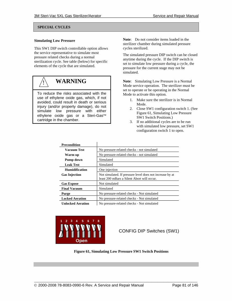
3M Steri-Vac 5XL Gas Sterilizer/Aerator Service and Repair Manual
______________________________________________________________________________________ © 2000-2008 78-8083-0990-6 Rev. A Service and Repair Manual Page 81 of 146
SPECIAL CYCLES
Simulating Low Pressure
This SW1 DIP switch controllable option allows the service representative to simulate most pressure related checks during a normal sterilization cycle. See table (below) for specific elements of the cycle that are simulated.
WARNING
To reduce the risks associated with the use of ethylene oxide gas, which, if not avoided, could result in death or serious injury (and/or property damage), do not simulate low pressure with either ethylene oxide gas or a Steri-Gas™ cartridge in the chamber.
Note: Do not consider items loaded in the sterilizer chamber during simulated pressure cycles sterilized.
The simulated pressure DIP switch can be closed anytime during the cycle. If the DIP switch is set to simulate low pressure during a cycle, the pressure for the current stage may not be simulated.
Note: Simulating Low Pressure is a Normal Mode service operation. The sterilizer must be set to operate or be operating in the Normal Mode to activate this option.
1. Make sure the sterilizer is in Normal Mode.
2. Close SW1 configuration switch 1. (See Figure 61, Simulating Low Pressure SW1 Switch Positions.)
3. If no additional cycles are to be run with simulated low pressure, set SW1 configuration switch 1 to open.
Precondition Vacuum Test No pressure-related checks - not simulated Warm up No pressure-related checks - not simulated Pump down Simulated Leak Test Simulated Humidification One injection
Gas Injection Not simulated. If pressure level does not increase by at least 200 mBars a Silent Abort will occur.
Gas Expose Not simulated Final Vacuum Simulated Purge No pressure-related checks - Not simulated Locked Aeration No pressure-related checks - Not simulated Unlocked Aeration No pressure-related checks - Not simulated
Open
1 2 3 4
CONFIG DIP Switches (SW1)
5 6 7 8
Figure 61, Simulating Low Pressure SW1 Switch Positions
!
3M Steri-Vac 5XL Gas Sterilizer/Aerator Service and Repair Manual
______________________________________________________________________________________ © 2000-2008 78-8083-0990-6 Rev. A Service and Repair Manual Page 82 of 146
SPECIAL CYCLES
Programming a New Machine Personality Code (MPC Build Code)
This programming procedure is intended for authorized Service Personnel only. It is critical that the correct Machine Personality Code (MPC) is used to match the intended use of the Sterilizer. If there is any question on programming or use of the MPC, contact your certified 3M Service Representative. Before performing this procedure, record any non-default Site Setup Information that must be retained. This procedure sets all Site Setup Information to default values.
1. Place the sterilizer in Standby Mode. 2. Cycle Power off. 3. Set SW1 Positions 1,7,8 to the ON
position. 4. Cycle Power on. 5. Enter the Master Code. 6. The Change Machine Code Screen will
now be visible. Using the Up and Down softkeys, to display the desired characters, press Select to enter the code character. Enter two letter keys followed by number key followed by 3 common letter keys. There is no need to select the Done softkey.
7. If a valid code was entered, 'MID = # will be displayed. (Otherwise, the machine defaults to MID = 11.)
8. Set SW1 Positions 1,7,8 back to the off position; otherwise, when power is cycled you will need to reprogram.
9. Perform the Reset Site Setup Information and Reset Cycle To Idle procedures.
10. If necessary, using the Site Setup menu reenter any Site Setup Information that had to be retained from the previous Machine Personality.
3M Steri-Vac 5XL Gas Sterilizer/Aerator Service and Repair Manual
______________________________________________________________________________________ © 2000-2008 78-8083-0990-6 Rev. A Service and Repair Manual Page 83 of 146
ILLUSTRATED PARTS BREAKDOWN
Parts Listing Table of Contents
Title Page Final Assembly, One Door 85 Final Assembly, Two Door 88 Chamber Assembly, One Door 91 Chamber Assembly, Two Door 94 Services-In Assembly, One Door 97 Services-In Assembly, Two Door 99 Manifold Assembly, One Door 101 Manifold Assembly, Two Door 103 Display Panel Assembly 105 Water Reservoir Assembly 107 Chamber Heater Assembly 109 Heat Sink Assembly 111 Door Assembly (Load Side) 113 Door Assembly (Unload Side) 115 Controller Bracket Assembly 117 Printer Assembly 119 Base Assembly, One Door 121 Base Assembly, Two Door 123 Back Plate Assembly 125 Door Interlock Assembly (Load Side) 127 Door Interlock Assembly (Unload Side) 129 Exhaust Hood Assembly (Load Side) 131 Exhaust Hood Assembly (Unload Side) 133
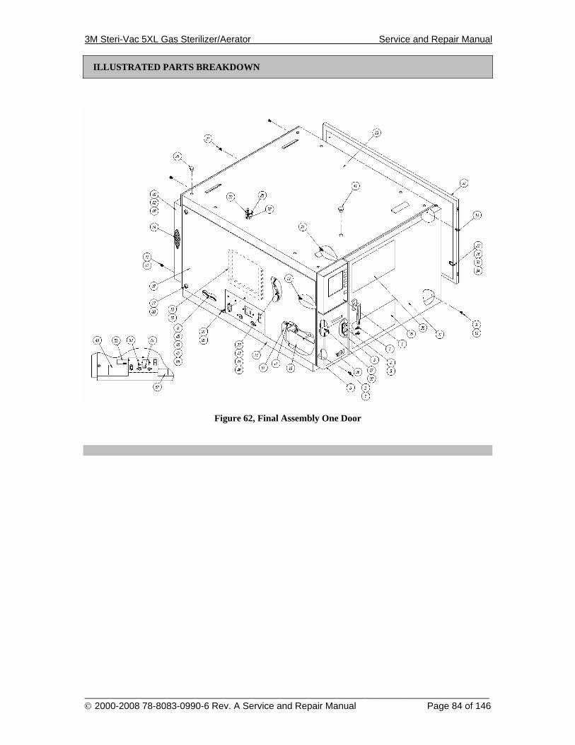
3M Steri-Vac 5XL Gas Sterilizer/Aerator Service and Repair Manual
______________________________________________________________________________________ © 2000-2008 78-8083-0990-6 Rev. A Service and Repair Manual Page 84 of 146
ILLUSTRATED PARTS BREAKDOWN
Figure 62, Final Assembly One Door
3M Steri-Vac 5XL Gas Sterilizer/Aerator Service and Repair Manual
______________________________________________________________________________________ © 2000-2008 78-8083-0990-6 Rev. A Service and Repair Manual Page 85 of 146
ILLUSTRATED PARTS BREAKDOWN
Final Assembly One Door
Item No. Part Number Description Qty 0 .....................78-8078-8396-8..... FINAL ASSEMBLY ONE DOOR.....................................................................REF 1 .....................78-8078-7596-4..... DISPLAY PANEL ASSEMBLY ....................................................................... 1 2 .....................26-1001-8627-4..... SCREW, 6-32 X .250, BUTTON HEAD ........................................................... 8 3 .....................26-1001-7983-2..... NUT, 6-32, KEPS............................................................................................... 2 4 .....................12-2376-9326-7..... BRACKET, MAGNETIC CATCH .................................................................... 1 5 .....................78-8005-4273-6..... CATCH, MAGNETIC........................................................................................ 1 6 .....................78-8078-7582-4..... WELDMENT, DOOR PRINTER/WATER ....................................................... 1 7 .....................12-2376-9330-9..... HINGE, PRINTER/WATER DOOR.................................................................. 1 8 .....................78-8078-4611-4..... WIRING HARNESS, HIGH VOLTAGE...........................................................REF 9 .....................26-1005-0964-0..... SCREW, 10-32 X .750, FLAT HEAD ............................................................... 2 10 ...................12-2376-9163-4..... ASSEMBLY, WATER RESERVOIR................................................................ 1 11 ...................26-1002-5224-1..... SCREW, 8-32 X .250, PAN HEAD ................................................................... 2 12 ...................26-1002-8892-2..... NUT, 10-32, KEPS............................................................................................. 4 13 ...................26-1002-5319-9..... SCREW, 8-32 X .500, FLAT HEAD ................................................................. 4 14 ...................78-8078-8399-2..... BASE ASSEMBLY............................................................................................ 1 15 ...................12-2376-9162-6..... POCKET RECORDS ......................................................................................... 1 16 ...................70-0024-8105-2..... TAPE .................................................................................................................AR 17 ...................26-1006-9926-8..... CAPTIVE WASHER ......................................................................................... 4 18 ...................78-8055-6030-3..... LEFT SIDE PANEL........................................................................................... 1 19 ...................78-8055-6037-8..... BACK PANEL ................................................................................................... 1 20 ...................26-1006-9927-6..... FASTENER, CAPTIVE SCREW ...................................................................... 4 21 ...................26-1002-5278-7..... SCREW, 8-32 X .500, PAN HEAD ................................................................... 6 22 ...................26-1004-2053-3..... WASHER, LOCK, #8 ....................................................................................... 3 23 ...................78-8078-6725-0..... WIRING HARNESS, LOW VOLTAGE............................................................ 1 24 ...................12-2376-3865-0..... INSULATION.................................................................................................... 1 25 ...................78-8033-1233-5..... CAPLUG............................................................................................................ 8 26 ...................26-1003-4963-3..... TERMINAL, AMP............................................................................................. 2 27 ...................78-8078-8339-8..... PRINTER ASSEMBLY ..................................................................................... 1 28 ...................26-1002-5266-2..... SCREW, 6-32 X .250, PAN HEAD ................................................................... 3 29 ...................78-8055-6032-9..... TOP PANEL....................................................................................................... 1 30 ...................78-8078-8441-2..... DECAL, OPERATING INSTRUCTIONS......................................................... 1 31 ...................78-8078-8393-5..... ASSEMBLY, CHAMBER, SINGLE DOOR ..................................................... 1 32 ...................78-8055-6031-1..... RIGHT SIDE PANEL ........................................................................................ 1 33 ...................26-1000-6654-2..... NUT, 8-32, KEPS............................................................................................... 2 34 ...................26-1004-3600-0..... SCREW, 8-32 X .375, BUTTON HEAD ........................................................... 1 35 ...................78-8078-7181-5..... DECAL, HEALTH AND SAFETY ................................................................... 1 35A ................78-8055-5721-8..... DECAL, DANGER (FRENCH/ENGLISH) ....................................................... REF 36 ...................78-8055-6054-3..... DECAL, 5XL DOOR LOGO ............................................................................. 1 37 ...................78-8078-8442-0..... SCHEMATIC, PNEUMATIC/WATER............................................................. REF 38 ...................12-2376-8585-9..... FIELD KIT & TOOL TABULATION ...............................................................REF 39 ...................78-8078-8443-8..... SCHEMATIC, 5XL............................................................................................REF 40 ...................12-2376-9802-7..... KIT, TUV VAC & TEMP TEST........................................................................REF 41 ...................26-1004-8899-3..... SCREW, 10-32 X .750, PAN HEAD ................................................................. 2 43 ...................26-1007-2093-2..... TERMINAL, AMP, .187 ................................................................................. 3 44 ...................78-8005-0588-1..... CAPLUG............................................................................................................ 1 45 ...................78-8011-2621-6..... BASE-MOUNTING, CABLE TIE, ................................................................... 5 46 ...................78-8005-8561-0..... TIE WRAP ......................................................................................................... 10
3M Steri-Vac 5XL Gas Sterilizer/Aerator Service and Repair Manual
______________________________________________________________________________________ © 2000-2008 78-8083-0990-6 Rev. A Service and Repair Manual Page 86 of 146
ILLUSTRATED PARTS BREAKDOWN
Item No. Part Number Description Qty 47 ...................78-8033-1354-9..... CLAMP, SCOTCHFLEX................................................................................... 2 48 ...................26-1007-2190-6..... HOLE PLUG, . 875 X 0.770 .............................................................................. 1 49 ...................12-2376-9835-7..... LABEL, INSTALLATION REQUIREMENTS................................................. 1 51 ...................78-8078-8444-6..... SERIAL PLATE-5XL ........................................................................................ 1 52 ...................78-8121-0858-3..... DECAL, FCC ..................................................................................................... 1 53 ...................12-2376-9836-5..... DECAL, POISON .............................................................................................. 1 55 ...................78-8000-7621-4..... CONNECTOR.................................................................................................... 14
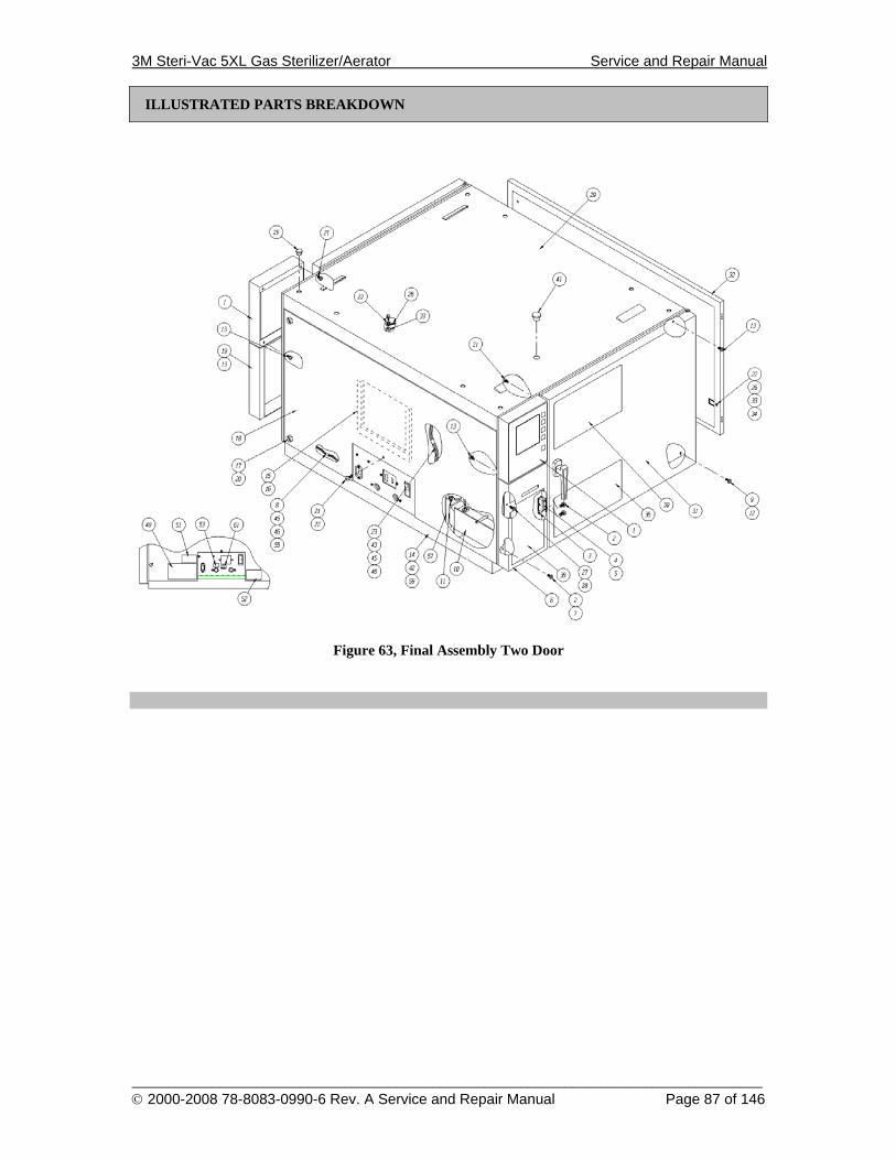
3M Steri-Vac 5XL Gas Sterilizer/Aerator Service and Repair Manual
______________________________________________________________________________________ © 2000-2008 78-8083-0990-6 Rev. A Service and Repair Manual Page 87 of 146
ILLUSTRATED PARTS BREAKDOWN
Figure 63, Final Assembly Two Door
3M Steri-Vac 5XL Gas Sterilizer/Aerator Service and Repair Manual
______________________________________________________________________________________ © 2000-2008 78-8083-0990-6 Rev. A Service and Repair Manual Page 88 of 146
ILLUSTRATED PARTS BREAKDOWN
Final Assembly Two Door
Item No. Part Number Description Qty 0 .....................78-8078-8397-6..... FINAL ASSEMBLY TWO DOOR....................................................................REF 1 .....................78-8078-7596-4..... DISPLAY PANEL ASSEMBLY ....................................................................... 2 2 .....................26-1001-8627-4..... SCREW, 6-32 X .250, BUTTON HEAD ........................................................... 8 3 .....................26-1001-7983-2..... NUT, 6-32, KEPS............................................................................................... 2 4 .....................12-2376-9326-7..... BRACKET, MAGNETIC CATCH .................................................................... 1 5 .....................78-8005-4273-6..... CATCH, MAGNETIC........................................................................................ 1 6 .....................78-8078-7582-4..... WELDMENT, DOOR PRINTER/WATER ....................................................... 1 7 .....................12-2376-9330-9..... HINGE, PRINTER/WATER DOOR.................................................................. 1 8 .....................78-8078-4611-4..... WIRING HARNESS, HIGH VOLTAGE...........................................................REF 9 .....................26-1005-0964-0..... SCREW, 10-32 X .750, FLAT HEAD ............................................................... 4 10 ...................12-2376-9163-4..... ASSEMBLY, WATER RESERVOIR................................................................ 1 11 ...................26-1002-5224-1..... SCREW, 8-32 X .250, PAN HEAD ................................................................... 2 12 ...................26-1002-8892-2..... NUT, 10-32, KEPS............................................................................................. 4 13 ...................26-1002-5319-9..... SCREW, 8-32 X .500, FLAT HEAD ................................................................. 10 14 ...................78-8078-8399-2..... BASE ASSEMBLY............................................................................................ 1 15 ...................12-2376-9162-6..... POCKET RECORDS ......................................................................................... 1 16 ...................70-0024-8105-2..... TAPE..................................................................................................................AR 17 ...................26-1006-9926-8..... CAPTIVE SCREW, 3/4 DIA X 1.25.................................................................. 4 18 ...................78-8055-6030-3..... LEFT SIDE PANEL........................................................................................... 1 19 ...................78-8055-6036-0..... COVER, UNLOAD SIDE .................................................................................. 1 20 ...................26-1006-9927-6..... CAPTIVE WASHER ......................................................................................... 4 21 ...................26-1002-5278-7..... SCREW, 8-32 X .500, PAN HEAD ................................................................... 5 22 ...................26-1004-2053-3..... WASHER, LOCK, #8 ....................................................................................... 3 23 ...................78-8078-6725-0..... WIRING HARNESS, LOW VOLTAGE............................................................ 1 25 ...................78-8033-1233-5..... CAPLUG, .250 ID X .560 OD............................................................................ 8 26 ...................26-1003-4963-3..... TERMINAL, .250............................................................................................... 2 27 ...................78-8078-8339-8..... PRINTER ASSEMBLY ..................................................................................... 1 28 ...................26-1002-5266-2..... SCREW, 6-32 X .250, PAN HEAD ................................................................... 3 29 ...................78-8055-6032-9..... TOP PANEL....................................................................................................... 1 30 ...................78-8078-8441-2..... DECAL, OPERATING INSTRUCTIONS......................................................... 2 31 ...................78-8078-8398-4..... CHAMBER ASSEMBLY, 2 DOOR .................................................................. 1 32 ...................78-8055-6031-1..... RIGHT SIDE PANEL ........................................................................................ 1 33 ...................26-1000-6654-2..... NUT, 8-32, KEPS............................................................................................... 2 34 ...................26-1004-3600-0..... SCREW, 8-32 X .375, BUTTON HEAD ......................................................... 1 35 ...................78-8078-7181-5..... DECAL, HEALTH AND SAFETY ................................................................... 2 35A ................78-8055-5721-8..... DECAL, DANGER (FRENCH/ENGLISH) ....................................................... REF 36 ...................78-8055-6054-3..... DECAL, 5XL DOOR LOGO ............................................................................. 2 37 ...................78-8078-8442-0..... SCHEMATIC, PNEUMATIC/WATER............................................................. REF 39 ...................78-8078-8443-8..... SCHEMATIC-5XL ............................................................................................REF 40 ...................12-2376-9802-7..... KIT, TUV VAC & TEMP TEST........................................................................REF 41 ...................78-8005-0588-1..... CAPLUG, .500 ID X .860 OD............................................................................ 1 42 ...................78-8011-2621-6..... BASE-MOUNTING, CABLE TIE..................................................................... 2 43 ...................78-8005-8561-0..... TIE WRAP ......................................................................................................... 7 44 ...................78-8033-1354-9..... CLAMP .............................................................................................................. 2 45 ...................26-1004-3140-7..... BUSHING STRAIN RELIEF............................................................................. 1 46 ...................78-8005-8561-0..... TIE WRAP ......................................................................................................... 10 47 ...................78-8033-1354-9..... CLAMP
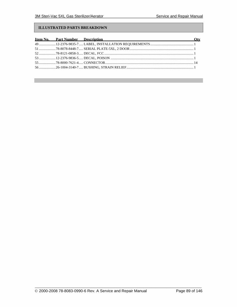
3M Steri-Vac 5XL Gas Sterilizer/Aerator Service and Repair Manual
______________________________________________________________________________________ © 2000-2008 78-8083-0990-6 Rev. A Service and Repair Manual Page 89 of 146
ILLUSTRATED PARTS BREAKDOWN
Item No. Part Number Description Qty 49 ...................12-2376-9835-7..... LABEL, INSTALLATION REQUIREMENTS................................................. 1 51 ...................78-8078-8448-7..... SERIAL PLATE-5XL, 2 DOOR ........................................................................ 1 52 ...................78-8121-0858-3..... DECAL, FCC ..................................................................................................... 1 53 ...................12-2376-9836-5..... DECAL, POISON .............................................................................................. 1 55 ...................78-8000-7621-4..... CONNECTOR.................................................................................................... 14 56 ...................26-1004-3140-7..... BUSHING, STRAIN RELIEF............................................................................ 1
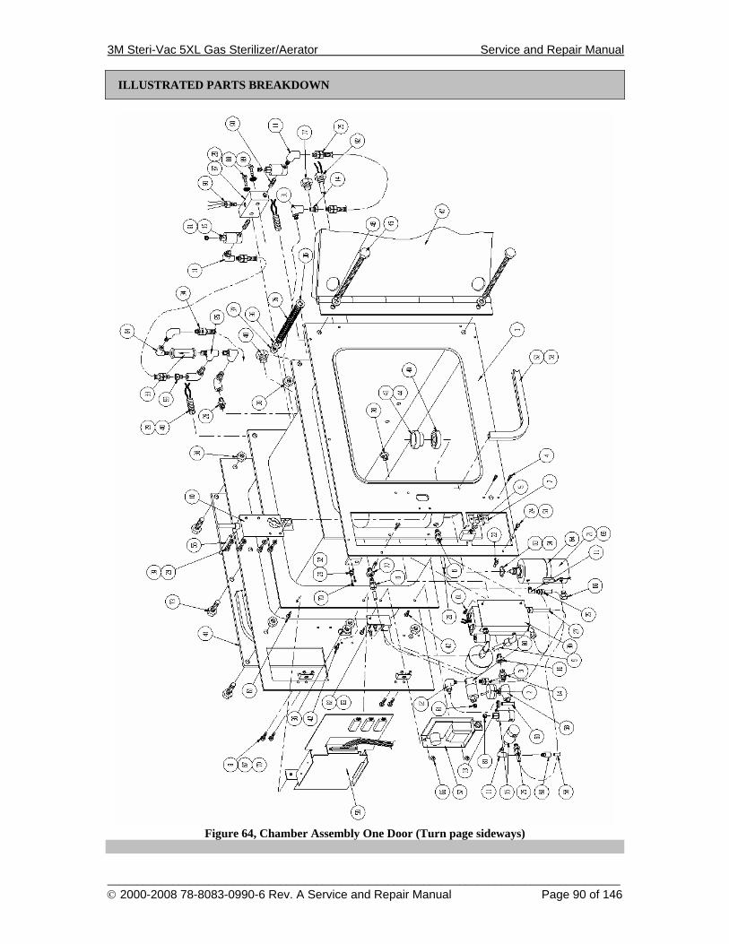
3M Steri-Vac 5XL Gas Sterilizer/Aerator Service and Repair Manual
______________________________________________________________________________________ © 2000-2008 78-8083-0990-6 Rev. A Service and Repair Manual Page 90 of 146
ILLUSTRATED PARTS BREAKDOWN
Figure 64, Chamber Assembly One Door (Turn page sideways)
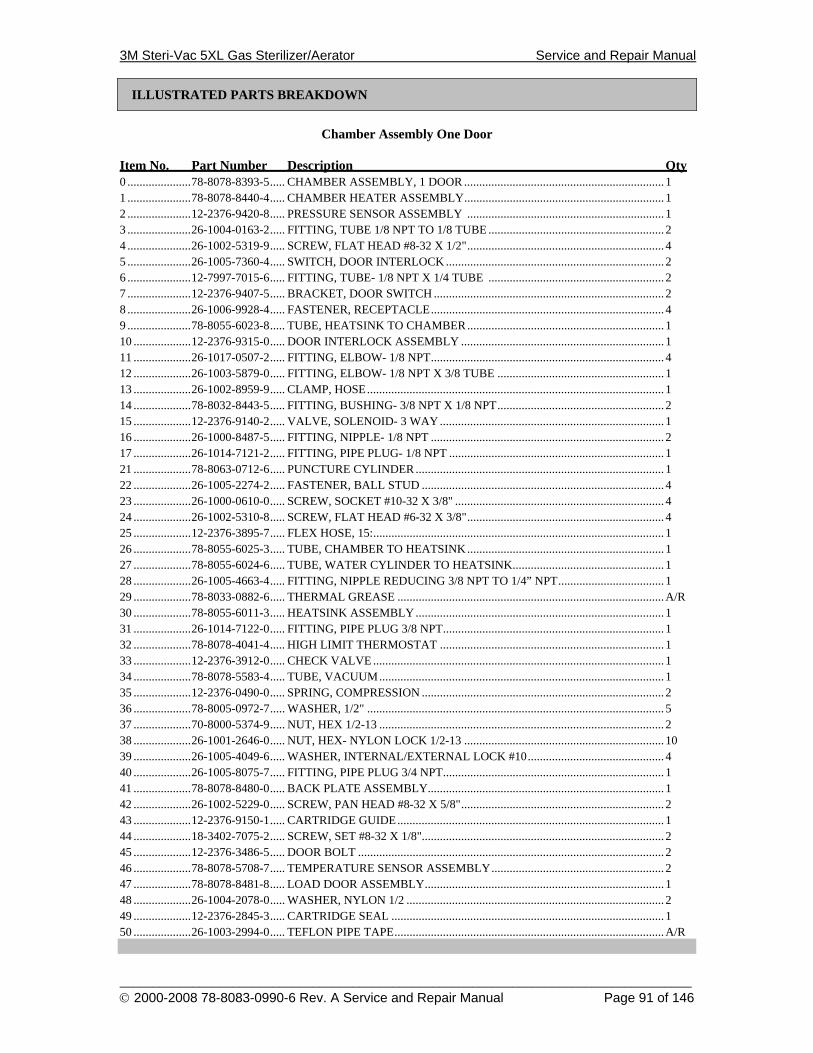
3M Steri-Vac 5XL Gas Sterilizer/Aerator Service and Repair Manual
______________________________________________________________________________________ © 2000-2008 78-8083-0990-6 Rev. A Service and Repair Manual Page 91 of 146
ILLUSTRATED PARTS BREAKDOWN
Chamber Assembly One Door
Item No. Part Number Description Qty 0 .....................78-8078-8393-5..... CHAMBER ASSEMBLY, 1 DOOR .................................................................. 1 1 .....................78-8078-8440-4..... CHAMBER HEATER ASSEMBLY.................................................................. 1 2 .....................12-2376-9420-8..... PRESSURE SENSOR ASSEMBLY ................................................................. 1 3 .....................26-1004-0163-2..... FITTING, TUBE 1/8 NPT TO 1/8 TUBE .......................................................... 2 4 .....................26-1002-5319-9..... SCREW, FLAT HEAD #8-32 X 1/2"................................................................. 4 5 .....................26-1005-7360-4..... SWITCH, DOOR INTERLOCK ........................................................................ 2 6 .....................12-7997-7015-6..... FITTING, TUBE- 1/8 NPT X 1/4 TUBE .......................................................... 2 7 .....................12-2376-9407-5..... BRACKET, DOOR SWITCH ............................................................................ 2 8 .....................26-1006-9928-4..... FASTENER, RECEPTACLE............................................................................. 4 9 .....................78-8055-6023-8..... TUBE, HEATSINK TO CHAMBER................................................................. 1 10 ...................12-2376-9315-0..... DOOR INTERLOCK ASSEMBLY ................................................................... 1 11 ...................26-1017-0507-2..... FITTING, ELBOW- 1/8 NPT............................................................................. 4 12 ...................26-1003-5879-0..... FITTING, ELBOW- 1/8 NPT X 3/8 TUBE ....................................................... 1 13 ...................26-1002-8959-9..... CLAMP, HOSE.................................................................................................. 1 14 ...................78-8032-8443-5..... FITTING, BUSHING- 3/8 NPT X 1/8 NPT....................................................... 2 15 ...................12-2376-9140-2..... VALVE, SOLENOID- 3 WAY .......................................................................... 1 16 ...................26-1000-8487-5..... FITTING, NIPPLE- 1/8 NPT ............................................................................. 2 17 ...................26-1014-7121-2..... FITTING, PIPE PLUG- 1/8 NPT ....................................................................... 1 21 ...................78-8063-0712-6..... PUNCTURE CYLINDER .................................................................................. 1 22 ...................26-1005-2274-2..... FASTENER, BALL STUD ................................................................................ 4 23 ...................26-1000-0610-0..... SCREW, SOCKET #10-32 X 3/8" ..................................................................... 4 24 ...................26-1002-5310-8..... SCREW, FLAT HEAD #6-32 X 3/8"................................................................. 4 25 ...................12-2376-3895-7..... FLEX HOSE, 15:................................................................................................ 1 26 ...................78-8055-6025-3..... TUBE, CHAMBER TO HEATSINK................................................................. 1 27 ...................78-8055-6024-6..... TUBE, WATER CYLINDER TO HEATSINK.................................................. 1 28 ...................26-1005-4663-4..... FITTING, NIPPLE REDUCING 3/8 NPT TO 1/4” NPT................................... 1 29 ...................78-8033-0882-6..... THERMAL GREASE ........................................................................................A/R 30 ...................78-8055-6011-3..... HEATSINK ASSEMBLY.................................................................................. 1 31 ...................26-1014-7122-0..... FITTING, PIPE PLUG 3/8 NPT......................................................................... 1 32 ...................78-8078-4041-4..... HIGH LIMIT THERMOSTAT .......................................................................... 1 33 ...................12-2376-3912-0..... CHECK VALVE ................................................................................................ 1 34 ...................78-8078-5583-4..... TUBE, VACUUM.............................................................................................. 1 35 ...................12-2376-0490-0..... SPRING, COMPRESSION ................................................................................ 2 36 ...................78-8005-0972-7..... WASHER, 1/2" .................................................................................................. 5 37 ...................70-8000-5374-9..... NUT, HEX 1/2-13 .............................................................................................. 2 38 ...................26-1001-2646-0..... NUT, HEX- NYLON LOCK 1/2-13 .................................................................. 10 39 ...................26-1005-4049-6..... WASHER, INTERNAL/EXTERNAL LOCK #10............................................. 4 40 ...................26-1005-8075-7..... FITTING, PIPE PLUG 3/4 NPT......................................................................... 1 41 ...................78-8078-8480-0..... BACK PLATE ASSEMBLY.............................................................................. 1 42 ...................26-1002-5229-0..... SCREW, PAN HEAD #8-32 X 5/8"................................................................... 2 43 ...................12-2376-9150-1..... CARTRIDGE GUIDE........................................................................................ 1 44 ...................18-3402-7075-2..... SCREW, SET #8-32 X 1/8"................................................................................ 2 45 ...................12-2376-3486-5..... DOOR BOLT ..................................................................................................... 2 46 ...................78-8078-5708-7..... TEMPERATURE SENSOR ASSEMBLY......................................................... 2 47 ...................78-8078-8481-8..... LOAD DOOR ASSEMBLY............................................................................... 1 48 ...................26-1004-2078-0..... WASHER, NYLON 1/2 ..................................................................................... 2 49 ...................12-2376-2845-3..... CARTRIDGE SEAL .......................................................................................... 1 50 ...................26-1003-2994-0..... TEFLON PIPE TAPE.........................................................................................A/R
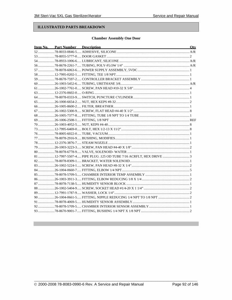
3M Steri-Vac 5XL Gas Sterilizer/Aerator Service and Repair Manual
______________________________________________________________________________________ © 2000-2008 78-8083-0990-6 Rev. A Service and Repair Manual Page 92 of 146
ILLUSTRATED PARTS BREAKDOWN
Chamber Assembly One Door
Item No. Part Number Description Qty 52 ...................78-8033-0846-5..... ADHESIVE, SILICONE ....................................................................................A/R 53 ...................78-8055-5777-0..... DOOR GASKET ................................................................................................ 2 54 ...................78-8933-1006-6..... LUBRICANT, SILICONE .................................................................................A/R 56 ...................78-8678-2261-7..... TUBING, POLY-FLOW 1/4" ............................................................................A/R 57 ...................78-8078-6063-6..... POWER SUPPLY ASSEMBLY, 5VDC............................................................ 1 58 ...................12-7995-0202-1..... FITTING, TEE 1/8 NPT..................................................................................... 1 59 ...................78-8678-7597-2..... CONTROLLER BRACKET ASSEMBLY ........................................................ 1 60 ...................26-1003-5452-6..... TUBING, URETHANE 3/8................................................................................A/R 61 ...................26-1002-7761-0..... SCREW, PAN HEAD #10-32 X 5/8"................................................................. 4 63 ...................12-2376-0602-0..... O-RING.............................................................................................................. 1 64 ...................78-8078-0333-9..... SWITCH, PUNCTURE CYLINDER................................................................. 1 65 ...................26-1000-6654-2..... NUT, HEX KEPS #8-32..................................................................................... 2 66 ...................26-1005-8600-2..... FILTER, BREATHER........................................................................................ 1 67 ...................26-1002-5300-9..... SCREW, FLAT HEAD #4-40 X 1/2"................................................................. 8 68 ...................26-1005-7377-8..... FITTING, TUBE 1/8 NPT TO 1/4 TUBE .......................................................... 1 69 ...................26-1006-2508-1..... FITTING, 1/8 NPT ............................................................................................REF 70 ...................26-1003-4052-5..... NUT, KEPS #4-40.............................................................................................. 8 73 ...................12-7995-6469-0..... BOLT, HEX 1/2-13 X 11/2"............................................................................... 8 76 ...................78-8005-6022-0..... TUBE, VACUUM.............................................................................................. 1 77 ...................78-8078-2916-9..... BUSHING, MODIFIES...................................................................................... 1 78 ...................12-2376-3876-7..... STEAM NOZZLE .............................................................................................. 1 79 ...................26-1003-3223-3..... SCREW, PAN HEAD #4-40 X 1/8"................................................................... 2 80 ...................78-8078-6778-9..... VALVE, SOLENOID- WATER ........................................................................ 1 81 ...................12-7997-5507-4..... PIPE PLUG .125 OD TUBE 7/16 ACRFLT, HEX DRIVE ............................... 3 82 ...................78-8078-8309-1..... BRACKET, WATER SOLENOID..................................................................... 1 83 ...................26-1002-5224-1..... SCREW, PAN HEAD #8-32 X 1/4"................................................................... 2 84 ...................26-1004-0660-7..... FITTING, ELBOW 1/4 NPT.............................................................................. 5 85 ...................78-8078-5709-5..... CHAMBER INTERIOR TEMP ASSEMBLY ................................................... 1 86 ...................26-1003-3911-3..... FITTING, ELBOW REDUCING 1/8 X 1/4 ....................................................... 2 87 ...................78-8078-7138-5..... HUMIDITY SENSOR BLOCK ......................................................................... 1 88 ...................26-1002-5404-9..... SCREW, SOCKET HEAD #1/4-20 X 1 1/4” ..................................................... 2 89 ...................12-7991-1787-9..... WASHER, LOCK 1/4”....................................................................................... 2 90 ...................26-1004-0661-5..... FITTING, NIPPLE REDUCING 1/4 NPT TO 1/8 NPT .................................... 2 91 ...................78-8078-4069-5..... HUMIDITY SENSOR ASSEMBLY.................................................................. 1 92 ...................78-8078-5709-5..... CHAMBER INTERIOR SENSOR ASSEMBLY............................................... 1 93 ...................78-8670-9001-7..... FITTING, BUSHING 1/4 NPT X 1/8 NPT ........................................................ 2
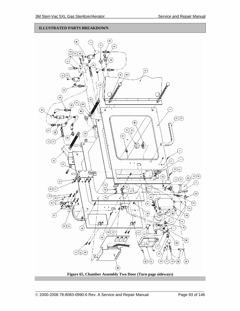
3M Steri-Vac 5XL Gas Sterilizer/Aerator Service and Repair Manual
______________________________________________________________________________________ © 2000-2008 78-8083-0990-6 Rev. A Service and Repair Manual Page 93 of 146
ILLUSTRATED PARTS BREAKDOWN
Figure 65, Chamber Assembly Two Door (Turn page sideways)
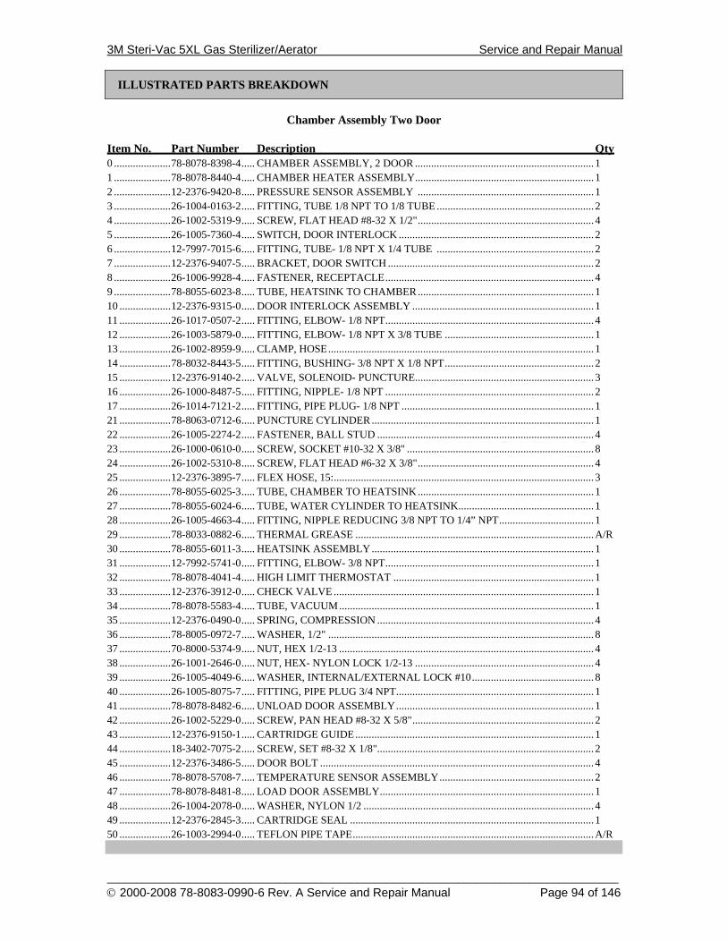
3M Steri-Vac 5XL Gas Sterilizer/Aerator Service and Repair Manual
______________________________________________________________________________________ © 2000-2008 78-8083-0990-6 Rev. A Service and Repair Manual Page 94 of 146
ILLUSTRATED PARTS BREAKDOWN
Chamber Assembly Two Door
Item No. Part Number Description Qty 0 .....................78-8078-8398-4..... CHAMBER ASSEMBLY, 2 DOOR .................................................................. 1 1 .....................78-8078-8440-4..... CHAMBER HEATER ASSEMBLY.................................................................. 1 2 .....................12-2376-9420-8..... PRESSURE SENSOR ASSEMBLY ................................................................. 1 3 .....................26-1004-0163-2..... FITTING, TUBE 1/8 NPT TO 1/8 TUBE .......................................................... 2 4 .....................26-1002-5319-9..... SCREW, FLAT HEAD #8-32 X 1/2"................................................................. 4 5 .....................26-1005-7360-4..... SWITCH, DOOR INTERLOCK ........................................................................ 2 6 .....................12-7997-7015-6..... FITTING, TUBE- 1/8 NPT X 1/4 TUBE .......................................................... 2 7 .....................12-2376-9407-5..... BRACKET, DOOR SWITCH ............................................................................ 2 8 .....................26-1006-9928-4..... FASTENER, RECEPTACLE............................................................................. 4 9 .....................78-8055-6023-8..... TUBE, HEATSINK TO CHAMBER................................................................. 1 10 ...................12-2376-9315-0..... DOOR INTERLOCK ASSEMBLY ................................................................... 1 11 ...................26-1017-0507-2..... FITTING, ELBOW- 1/8 NPT............................................................................. 4 12 ...................26-1003-5879-0..... FITTING, ELBOW- 1/8 NPT X 3/8 TUBE ....................................................... 1 13 ...................26-1002-8959-9..... CLAMP, HOSE.................................................................................................. 1 14 ...................78-8032-8443-5..... FITTING, BUSHING- 3/8 NPT X 1/8 NPT....................................................... 2 15 ...................12-2376-9140-2..... VALVE, SOLENOID- PUNCTURE.................................................................. 3 16 ...................26-1000-8487-5..... FITTING, NIPPLE- 1/8 NPT ............................................................................. 2 17 ...................26-1014-7121-2..... FITTING, PIPE PLUG- 1/8 NPT ....................................................................... 1 21 ...................78-8063-0712-6..... PUNCTURE CYLINDER .................................................................................. 1 22 ...................26-1005-2274-2..... FASTENER, BALL STUD ................................................................................ 4 23 ...................26-1000-0610-0..... SCREW, SOCKET #10-32 X 3/8" ..................................................................... 8 24 ...................26-1002-5310-8..... SCREW, FLAT HEAD #6-32 X 3/8"................................................................. 4 25 ...................12-2376-3895-7..... FLEX HOSE, 15:................................................................................................ 3 26 ...................78-8055-6025-3..... TUBE, CHAMBER TO HEATSINK................................................................. 1 27 ...................78-8055-6024-6..... TUBE, WATER CYLINDER TO HEATSINK.................................................. 1 28 ...................26-1005-4663-4..... FITTING, NIPPLE REDUCING 3/8 NPT TO 1/4” NPT................................... 1 29 ...................78-8033-0882-6..... THERMAL GREASE ........................................................................................A/R 30 ...................78-8055-6011-3..... HEATSINK ASSEMBLY.................................................................................. 1 31 ...................12-7992-5741-0..... FITTING, ELBOW- 3/8 NPT............................................................................. 1 32 ...................78-8078-4041-4..... HIGH LIMIT THERMOSTAT .......................................................................... 1 33 ...................12-2376-3912-0..... CHECK VALVE ................................................................................................ 1 34 ...................78-8078-5583-4..... TUBE, VACUUM.............................................................................................. 1 35 ...................12-2376-0490-0..... SPRING, COMPRESSION ................................................................................ 4 36 ...................78-8005-0972-7..... WASHER, 1/2" .................................................................................................. 8 37 ...................70-8000-5374-9..... NUT, HEX 1/2-13 .............................................................................................. 4 38 ...................26-1001-2646-0..... NUT, HEX- NYLON LOCK 1/2-13 .................................................................. 4 39 ...................26-1005-4049-6..... WASHER, INTERNAL/EXTERNAL LOCK #10............................................. 8 40 ...................26-1005-8075-7..... FITTING, PIPE PLUG 3/4 NPT......................................................................... 1 41 ...................78-8078-8482-6..... UNLOAD DOOR ASSEMBLY......................................................................... 1 42 ...................26-1002-5229-0..... SCREW, PAN HEAD #8-32 X 5/8"................................................................... 2 43 ...................12-2376-9150-1..... CARTRIDGE GUIDE........................................................................................ 1 44 ...................18-3402-7075-2..... SCREW, SET #8-32 X 1/8"................................................................................ 2 45 ...................12-2376-3486-5..... DOOR BOLT ..................................................................................................... 4 46 ...................78-8078-5708-7..... TEMPERATURE SENSOR ASSEMBLY......................................................... 2 47 ...................78-8078-8481-8..... LOAD DOOR ASSEMBLY............................................................................... 1 48 ...................26-1004-2078-0..... WASHER, NYLON 1/2 ..................................................................................... 4 49 ...................12-2376-2845-3..... CARTRIDGE SEAL .......................................................................................... 1 50 ...................26-1003-2994-0..... TEFLON PIPE TAPE.........................................................................................A/R
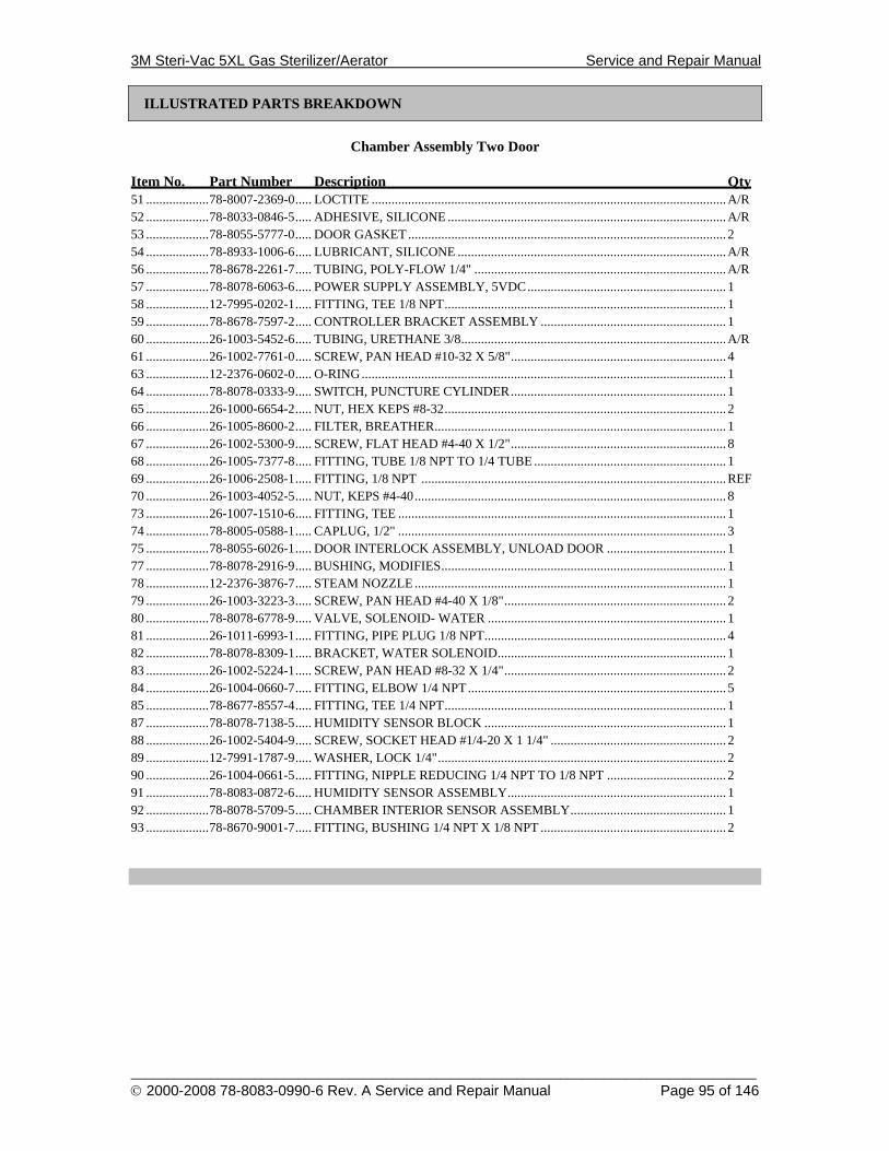
3M Steri-Vac 5XL Gas Sterilizer/Aerator Service and Repair Manual
______________________________________________________________________________________ © 2000-2008 78-8083-0990-6 Rev. A Service and Repair Manual Page 95 of 146
ILLUSTRATED PARTS BREAKDOWN
Chamber Assembly Two Door
Item No. Part Number Description Qty 51 ...................78-8007-2369-0..... LOCTITE ...........................................................................................................A/R 52 ...................78-8033-0846-5..... ADHESIVE, SILICONE ....................................................................................A/R 53 ...................78-8055-5777-0..... DOOR GASKET ................................................................................................ 2 54 ...................78-8933-1006-6..... LUBRICANT, SILICONE .................................................................................A/R 56 ...................78-8678-2261-7..... TUBING, POLY-FLOW 1/4" ............................................................................A/R 57 ...................78-8078-6063-6..... POWER SUPPLY ASSEMBLY, 5VDC............................................................ 1 58 ...................12-7995-0202-1..... FITTING, TEE 1/8 NPT..................................................................................... 1 59 ...................78-8678-7597-2..... CONTROLLER BRACKET ASSEMBLY ........................................................ 1 60 ...................26-1003-5452-6..... TUBING, URETHANE 3/8................................................................................A/R 61 ...................26-1002-7761-0..... SCREW, PAN HEAD #10-32 X 5/8"................................................................. 4 63 ...................12-2376-0602-0..... O-RING.............................................................................................................. 1 64 ...................78-8078-0333-9..... SWITCH, PUNCTURE CYLINDER................................................................. 1 65 ...................26-1000-6654-2..... NUT, HEX KEPS #8-32..................................................................................... 2 66 ...................26-1005-8600-2..... FILTER, BREATHER........................................................................................ 1 67 ...................26-1002-5300-9..... SCREW, FLAT HEAD #4-40 X 1/2"................................................................. 8 68 ...................26-1005-7377-8..... FITTING, TUBE 1/8 NPT TO 1/4 TUBE .......................................................... 1 69 ...................26-1006-2508-1..... FITTING, 1/8 NPT ............................................................................................REF 70 ...................26-1003-4052-5..... NUT, KEPS #4-40.............................................................................................. 8 73 ...................26-1007-1510-6..... FITTING, TEE ................................................................................................... 1 74 ...................78-8005-0588-1..... CAPLUG, 1/2" ................................................................................................... 3 75 ...................78-8055-6026-1..... DOOR INTERLOCK ASSEMBLY, UNLOAD DOOR .................................... 1 77 ...................78-8078-2916-9..... BUSHING, MODIFIES...................................................................................... 1 78 ...................12-2376-3876-7..... STEAM NOZZLE .............................................................................................. 1 79 ...................26-1003-3223-3..... SCREW, PAN HEAD #4-40 X 1/8"................................................................... 2 80 ...................78-8078-6778-9..... VALVE, SOLENOID- WATER ........................................................................ 1 81 ...................26-1011-6993-1..... FITTING, PIPE PLUG 1/8 NPT......................................................................... 4 82 ...................78-8078-8309-1..... BRACKET, WATER SOLENOID..................................................................... 1 83 ...................26-1002-5224-1..... SCREW, PAN HEAD #8-32 X 1/4"................................................................... 2 84 ...................26-1004-0660-7..... FITTING, ELBOW 1/4 NPT.............................................................................. 5 85 ...................78-8677-8557-4..... FITTING, TEE 1/4 NPT..................................................................................... 1 87 ...................78-8078-7138-5..... HUMIDITY SENSOR BLOCK ......................................................................... 1 88 ...................26-1002-5404-9..... SCREW, SOCKET HEAD #1/4-20 X 1 1/4" ..................................................... 2 89 ...................12-7991-1787-9..... WASHER, LOCK 1/4"....................................................................................... 2 90 ...................26-1004-0661-5..... FITTING, NIPPLE REDUCING 1/4 NPT TO 1/8 NPT .................................... 2 91 ...................78-8083-0872-6..... HUMIDITY SENSOR ASSEMBLY.................................................................. 1 92 ...................78-8078-5709-5..... CHAMBER INTERIOR SENSOR ASSEMBLY............................................... 1 93 ...................78-8670-9001-7..... FITTING, BUSHING 1/4 NPT X 1/8 NPT ........................................................ 2
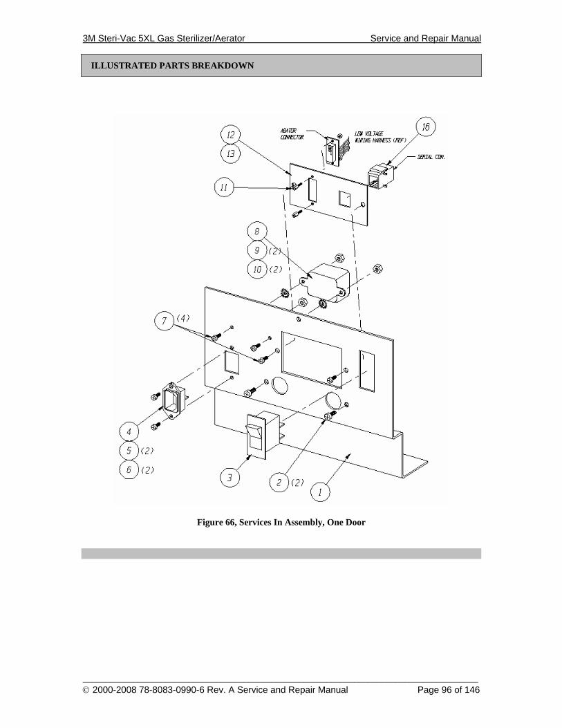
3M Steri-Vac 5XL Gas Sterilizer/Aerator Service and Repair Manual
______________________________________________________________________________________ © 2000-2008 78-8083-0990-6 Rev. A Service and Repair Manual Page 96 of 146
ILLUSTRATED PARTS BREAKDOWN
Figure 66, Services In Assembly, One Door
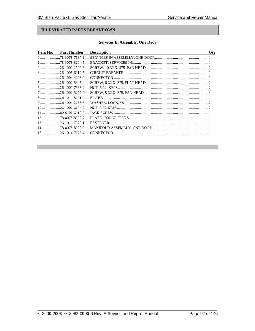
3M Steri-Vac 5XL Gas Sterilizer/Aerator Service and Repair Manual
______________________________________________________________________________________ © 2000-2008 78-8083-0990-6 Rev. A Service and Repair Manual Page 97 of 146
ILLUSTRATED PARTS BREAKDOWN
Services In Assembly, One Door
Item No. Part Number Description Qty 0 .....................78-8078-7587-3..... SERVICES IN ASSEMBLY, ONE DOOR........................................................ 1 1 .....................78-8078-8294-5..... BRACKET, SERVICES IN................................................................................ 1 2 .....................26-1002-2929-8..... SCREW, 10-32 X .375, PAN HEAD ................................................................. 2 3 .....................26-1005-6119-5..... CIRCUIT BREAKER......................................................................................... 1 4 .....................26-1004-4223-0..... CONNECTOR.................................................................................................... 1 5 .....................26-1002-5345-4..... SCREW, 6-32 X .375, FLAT HEAD ................................................................. 2 6 .....................26-1001-7983-2..... NUT, 6-32, KEPS............................................................................................... 2 7 .....................26-1002-5277-9..... SCREW, 8-32 X .375, PAN HEAD ................................................................... 4 8 .....................26-1011-8071-4..... FILTER ............................................................................................................. 1 9 .....................26-1004-2053-3..... WASHER, LOCK, #8 ....................................................................................... 2 10 ...................26-1000-6654-2..... NUT, 8-32,KEPS................................................................................................ 2 11 ...................80-6100-6110-5..... JACK SCREW .................................................................................................. 1 12 ...................78-8078-8392-7..... PLATE, CONNECTORS ................................................................................... 1 13 ...................26-1011-7370-1..... FASTENER ....................................................................................................... 1 14 ...................78-8078-8395-0..... MANIFOLD ASSEMBLY, ONE DOOR........................................................... 1 16 ...................26-1014-7078-4..... CONNECTOR.................................................................................................... 1
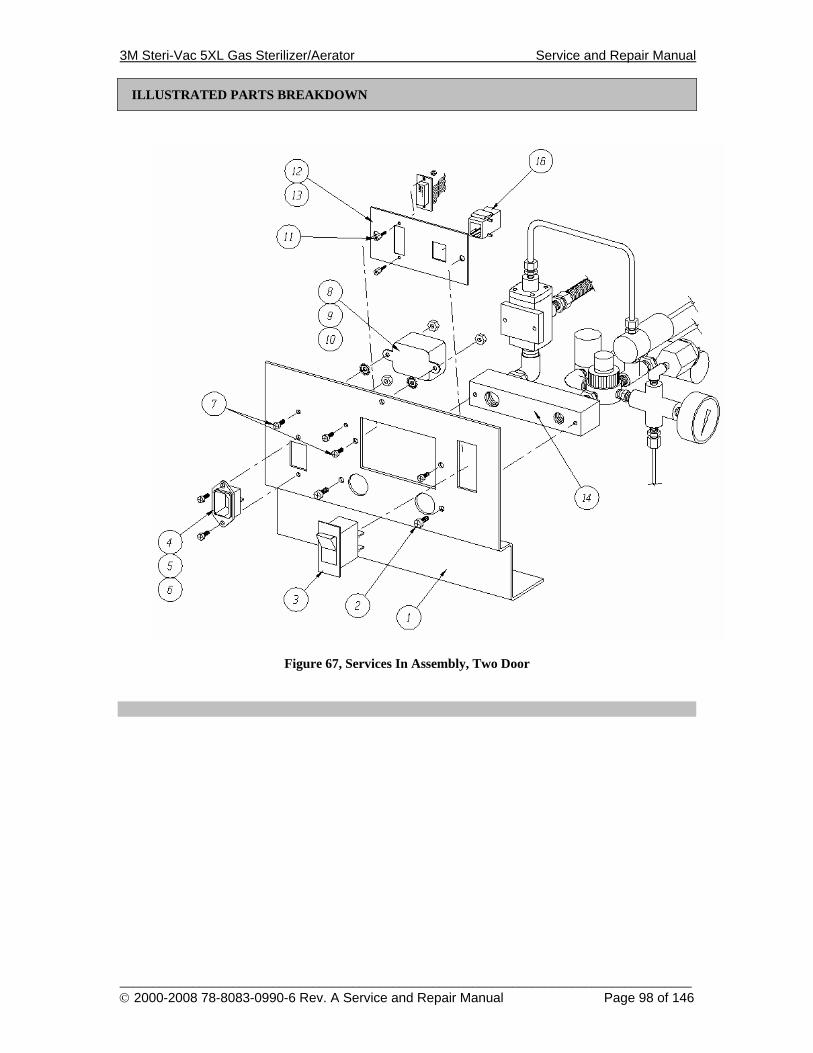
3M Steri-Vac 5XL Gas Sterilizer/Aerator Service and Repair Manual
______________________________________________________________________________________ © 2000-2008 78-8083-0990-6 Rev. A Service and Repair Manual Page 98 of 146
ILLUSTRATED PARTS BREAKDOWN
Figure 67, Services In Assembly, Two Door
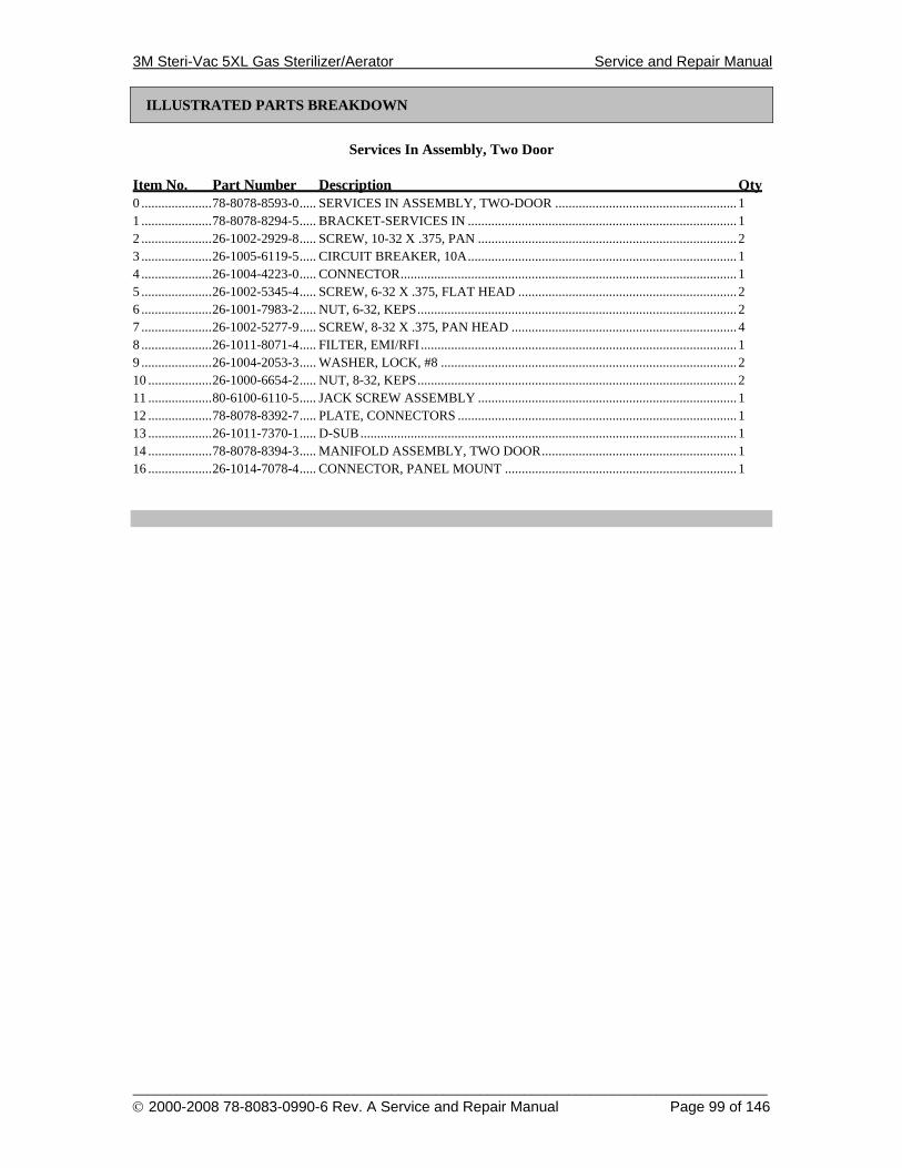
3M Steri-Vac 5XL Gas Sterilizer/Aerator Service and Repair Manual
______________________________________________________________________________________ © 2000-2008 78-8083-0990-6 Rev. A Service and Repair Manual Page 99 of 146
ILLUSTRATED PARTS BREAKDOWN
Services In Assembly, Two Door
Item No. Part Number Description Qty 0 .....................78-8078-8593-0..... SERVICES IN ASSEMBLY, TWO-DOOR ...................................................... 1 1 .....................78-8078-8294-5..... BRACKET-SERVICES IN ................................................................................ 1 2 .....................26-1002-2929-8..... SCREW, 10-32 X .375, PAN ............................................................................. 2 3 .....................26-1005-6119-5..... CIRCUIT BREAKER, 10A................................................................................ 1 4 .....................26-1004-4223-0..... CONNECTOR.................................................................................................... 1 5 .....................26-1002-5345-4..... SCREW, 6-32 X .375, FLAT HEAD ................................................................. 2 6 .....................26-1001-7983-2..... NUT, 6-32, KEPS............................................................................................... 2 7 .....................26-1002-5277-9..... SCREW, 8-32 X .375, PAN HEAD ................................................................... 4 8 .....................26-1011-8071-4..... FILTER, EMI/RFI .............................................................................................. 1 9 .....................26-1004-2053-3..... WASHER, LOCK, #8 ........................................................................................ 2 10 ...................26-1000-6654-2..... NUT, 8-32, KEPS............................................................................................... 2 11 ...................80-6100-6110-5..... JACK SCREW ASSEMBLY ............................................................................. 1 12 ...................78-8078-8392-7..... PLATE, CONNECTORS ................................................................................... 1 13 ...................26-1011-7370-1..... D-SUB................................................................................................................ 1 14 ...................78-8078-8394-3..... MANIFOLD ASSEMBLY, TWO DOOR.......................................................... 1 16 ...................26-1014-7078-4..... CONNECTOR, PANEL MOUNT ..................................................................... 1
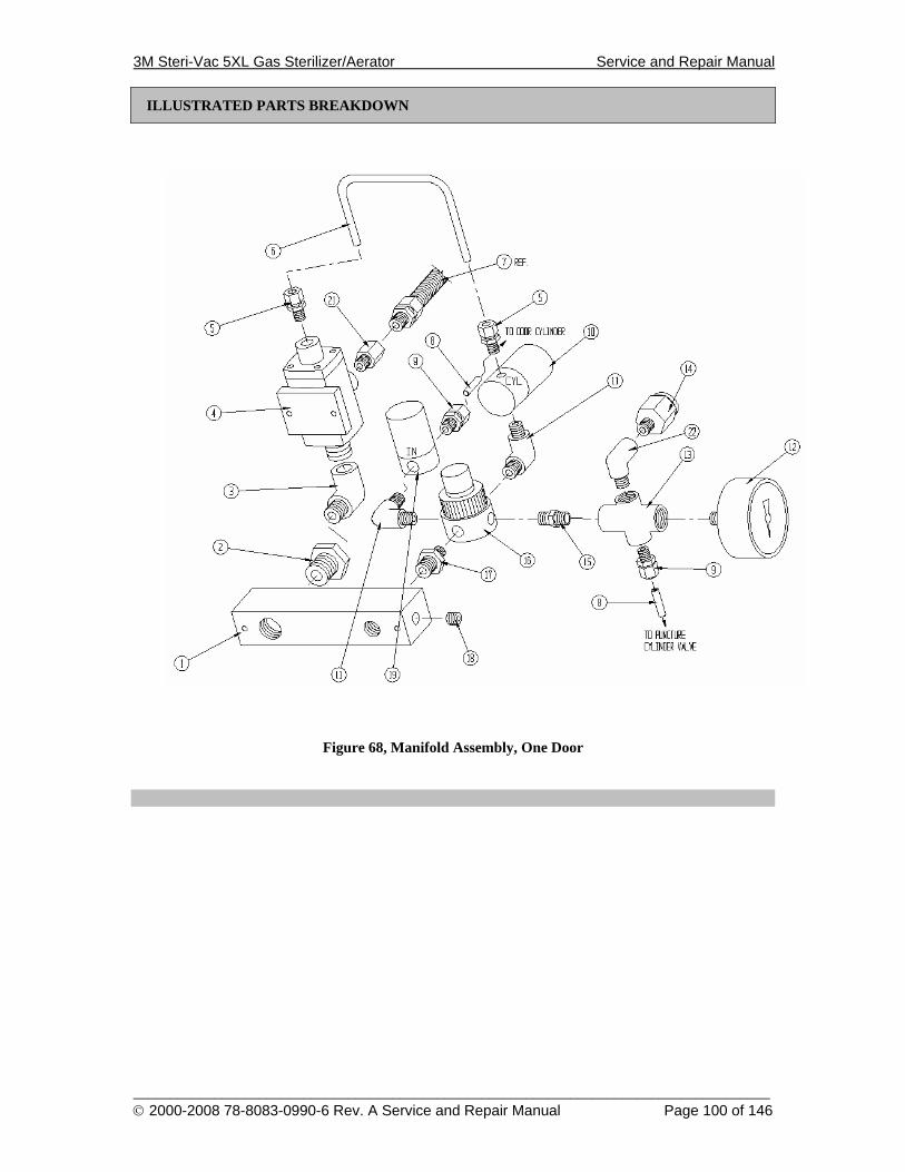
3M Steri-Vac 5XL Gas Sterilizer/Aerator Service and Repair Manual
______________________________________________________________________________________ © 2000-2008 78-8083-0990-6 Rev. A Service and Repair Manual Page 100 of 146
ILLUSTRATED PARTS BREAKDOWN
Figure 68, Manifold Assembly, One Door
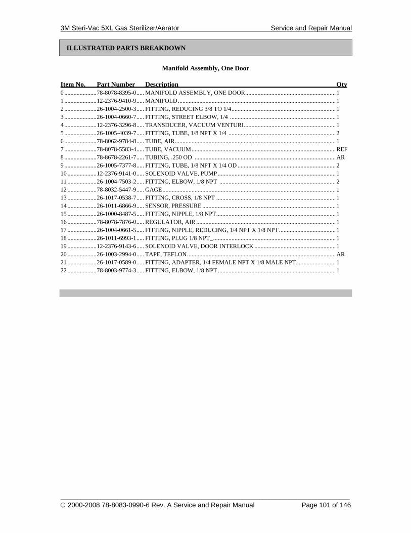
3M Steri-Vac 5XL Gas Sterilizer/Aerator Service and Repair Manual
______________________________________________________________________________________ © 2000-2008 78-8083-0990-6 Rev. A Service and Repair Manual Page 101 of 146
ILLUSTRATED PARTS BREAKDOWN
Manifold Assembly, One Door
Item No. Part Number Description Qty 0 .....................78-8078-8395-0..... MANIFOLD ASSEMBLY, ONE DOOR........................................................... 1 1 .....................12-2376-9410-9..... MANIFOLD....................................................................................................... 1 2 .....................26-1004-2500-3..... FITTING, REDUCING 3/8 TO 1/4.................................................................... 1 3 .....................26-1004-0660-7..... FITTING, STREET ELBOW, 1/4 ..................................................................... 1 4 .....................12-2376-3296-8..... TRANSDUCER, VACUUM VENTURI............................................................ 1 5 .....................26-1005-4039-7..... FITTING, TUBE, 1/8 NPT X 1/4 ...................................................................... 2 6 .....................78-8062-9784-8..... TUBE, AIR......................................................................................................... 1 7 .....................78-8078-5583-4..... TUBE, VACUUM..............................................................................................REF 8 .....................78-8678-2261-7..... TUBING, .250 OD ............................................................................................AR 9 .....................26-1005-7377-8..... FITTING, TUBE, 1/8 NPT X 1/4 OD ................................................................ 2 10 ...................12-2376-9141-0..... SOLENOID VALVE, PUMP............................................................................. 1 11 ...................26-1004-7503-2..... FITTING, ELBOW, 1/8 NPT ............................................................................ 2 12 ...................78-8032-5447-9..... GAGE................................................................................................................. 1 13 ...................26-1017-0538-7..... FITTING, CROSS, 1/8 NPT .............................................................................. 1 14 ...................26-1011-6866-9..... SENSOR, PRESSURE ....................................................................................... 1 15 ...................26-1000-8487-5..... FITTING, NIPPLE, 1/8 NPT.............................................................................. 1 16 ...................78-8078-7876-0..... REGULATOR, AIR ........................................................................................... 1 17 ...................26-1004-0661-5..... FITTING, NIPPLE, REDUCING, 1/4 NPT X 1/8 NPT..................................... 1 18 ...................26-1011-6993-1..... FITTING, PLUG 1/8 NPT_................................................................................ 1 19 ...................12-2376-9143-6..... SOLENOID VALVE, DOOR INTERLOCK ..................................................... 1 20 ...................26-1003-2994-0..... TAPE, TEFLON.................................................................................................AR 21 ...................26-1017-0589-0..... FITTING, ADAPTER, 1/4 FEMALE NPT X 1/8 MALE NPT.......................... 1 22 ...................78-8003-9774-3..... FITTING, ELBOW, 1/8 NPT............................................................................. 1
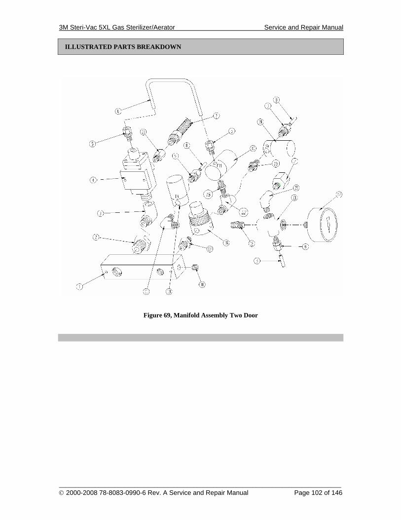
3M Steri-Vac 5XL Gas Sterilizer/Aerator Service and Repair Manual
______________________________________________________________________________________ © 2000-2008 78-8083-0990-6 Rev. A Service and Repair Manual Page 102 of 146
ILLUSTRATED PARTS BREAKDOWN
Figure 69, Manifold Assembly Two Door
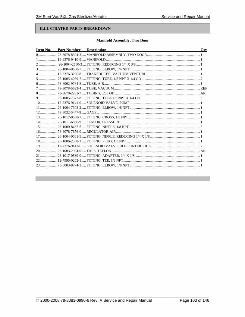
3M Steri-Vac 5XL Gas Sterilizer/Aerator Service and Repair Manual
______________________________________________________________________________________ © 2000-2008 78-8083-0990-6 Rev. A Service and Repair Manual Page 103 of 146
ILLUSTRATED PARTS BREAKDOWN
Manifold Assembly, Two Door
Item No. Part Number Description Qty 0 .....................78-8078-8394-3..... MANIFOLD ASSEMBLY, TWO DOOR.......................................................... 1 1 .....................12-2376-9410-9..... MANIFOLD....................................................................................................... 1 2 ..................... 26-1004-2500-3.... FITTING, REDUCING 1/4 X 3/8 ...................................................................... 1 3 .....................26-1004-0660-7..... FITTING, ELBOW, 1/4 NPT............................................................................. 1 4 .....................12-2376-3296-8..... TRANSDUCER, VACUUM VENTURI............................................................ 1 5 .....................26-1005-4039-7..... FITTING, TUBE, 1/8 NPT X 1/4 OD ................................................................ 2 6 .....................78-8062-9784-8..... TUBE, AIR......................................................................................................... 1 7 .....................78-8078-5583-4..... TUBE, VACUUM..............................................................................................REF 8 .....................78-8678-2261-7..... TUBING, .250 OD .............................................................................................AR 9 .....................26-1005-7377-8..... FITTING, TUBE 1/8 NPT X 1/4 OD ................................................................. 3 10 ...................12-2376-9141-0..... SOLENOID VALVE, PUMP............................................................................. 1 11 ...................26-1004-7503-2..... FITTING, ELBOW, 1/8 NPT............................................................................. 1 12 ...................78-8032-5447-9..... GAGE................................................................................................................. 1 13 ...................26-1017-0538-7..... FITTING, CROSS, 1/8 NPT .............................................................................. 1 14 ...................26-1011-6866-9..... SENSOR, PRESSURE ....................................................................................... 1 15 ...................26-1000-8487-5..... FITTING, NIPPLE, 1/8 NPT.............................................................................. 3 16 ...................78-8078-7876-0..... REGULATOR-AIR............................................................................................ 1 17 ...................26-1004-0661-5..... FITTING, NIPPLE, REDUCING 1/4 X 1/8....................................................... 1 18 ...................26-1006-2508-1..... FITTING, PLUG, 1/8 NPT _.............................................................................. 1 19 ...................12-2376-9143-6..... SOLENOID VALVE, DOOR INTERLOCK ..................................................... 2 20 ...................26-1003-2994-0..... TAPE, TEFLON.................................................................................................AR 21 ...................26-1017-0589-0..... FITTING, ADAPTER, 1/4 X 1/8 ...................................................................... 1 22 ...................12-7995-0202-1..... FITTING, TEE, 1/8 NPT.................................................................................... 1 23 ...................78-8003-9774-3..... FITTING, ELBOW, 1/8 NPT............................................................................. 1
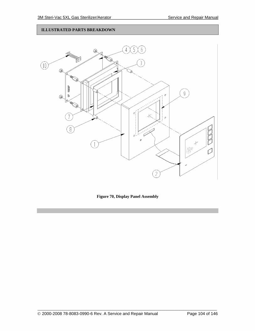
3M Steri-Vac 5XL Gas Sterilizer/Aerator Service and Repair Manual
______________________________________________________________________________________ © 2000-2008 78-8083-0990-6 Rev. A Service and Repair Manual Page 104 of 146
ILLUSTRATED PARTS BREAKDOWN
Figure 70, Display Panel Assembly
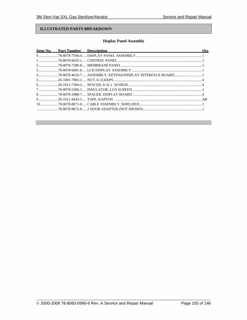
3M Steri-Vac 5XL Gas Sterilizer/Aerator Service and Repair Manual
______________________________________________________________________________________ © 2000-2008 78-8083-0990-6 Rev. A Service and Repair Manual Page 105 of 146
ILLUSTRATED PARTS BREAKDOWN
Display Panel Assembly
Item No. Part Number Description Qty 0 .....................78-8078-7596-4..... DISPLAY PANEL ASSEMBLY ....................................................................... 1 1 .....................78-8078-6635-1..... CONTROL PANEL ........................................................................................... 1 2 .....................78-8078-7580-8..... MEMBRANE PANEL ....................................................................................... 1 3 .....................78-8078-6081-8..... LCD DISPLAY ASSEMBLY ............................................................................ 1 4 .....................78-8078-4619-7..... ASSEMBLY, KEYPAD/DISPLAY INTERFACE BOARD.............................. 1 5 .....................26-1001-7983-2..... NUT, 6-32,KEPS................................................................................................ 4 6 .....................26-1011-7384-2..... SPACER, 6-32 x .50 HIGH................................................................................ 4 7 .....................78-8078-5396-1..... INSULATOR, LCD SCREEN ........................................................................... 1 8 .....................78-8078-3988-7..... SPACER, DISPLAY BOARD ........................................................................... 4 9 .....................26-1011-4435-5..... TAPE, KAPTON ...............................................................................................AR 10 ...................78-8078-8871-0..... CABLE ASSEMBLY, SHIELDED.................................................................... 1 .......................78-8078-8872-8..... 2 DOOR ADAPTER (NOT SHOWN) ............................................................... 1
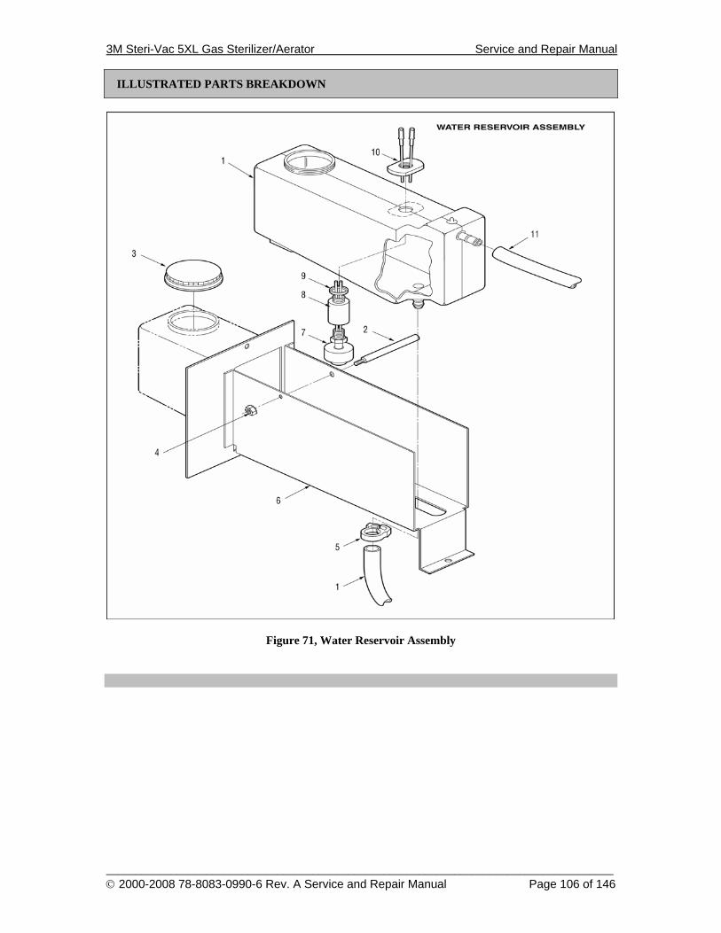
3M Steri-Vac 5XL Gas Sterilizer/Aerator Service and Repair Manual
______________________________________________________________________________________ © 2000-2008 78-8083-0990-6 Rev. A Service and Repair Manual Page 106 of 146
ILLUSTRATED PARTS BREAKDOWN
Figure 71, Water Reservoir Assembly
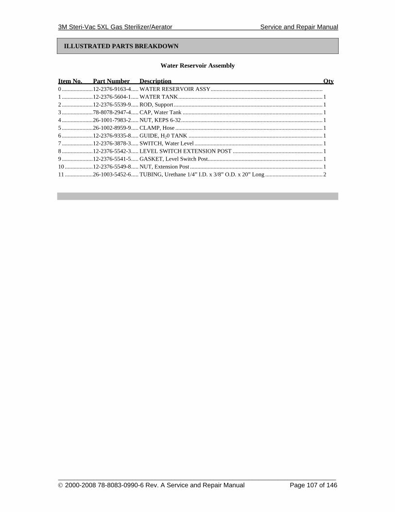
3M Steri-Vac 5XL Gas Sterilizer/Aerator Service and Repair Manual
______________________________________________________________________________________ © 2000-2008 78-8083-0990-6 Rev. A Service and Repair Manual Page 107 of 146
ILLUSTRATED PARTS BREAKDOWN
Water Reservoir Assembly
Item No. Part Number Description Qty 0 .....................12-2376-9163-4..... WATER RESERVOIR ASSY............................................................................ 1 .....................12-2376-5604-1..... WATER TANK.................................................................................................. 1 2 .....................12-2376-5539-9..... ROD, Support ..................................................................................................... 1 3 .....................78-8078-2947-4..... CAP, Water Tank ............................................................................................... 1 4 .....................26-1001-7983-2..... NUT, KEPS 6-32................................................................................................ 1 5 .....................26-1002-8959-9..... CLAMP, Hose .................................................................................................... 1 6 .....................12-2376-9335-8..... GUIDE, H20 TANK ........................................................................................... 1 7 .....................12-2376-3878-3..... SWITCH, Water Level ....................................................................................... 1 8 .....................12-2376-5542-3..... LEVEL SWITCH EXTENSION POST ............................................................. 1 9 .....................12-2376-5541-5..... GASKET, Level Switch Post.............................................................................. 1 10 ...................12-2376-5549-8..... NUT, Extension Post .......................................................................................... 1 11 ...................26-1003-5452-6..... TUBING, Urethane 1/4” I.D. x 3/8” O.D. x 20” Long ....................................... 2
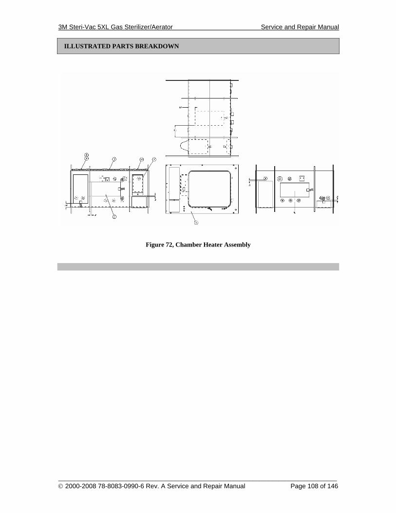
3M Steri-Vac 5XL Gas Sterilizer/Aerator Service and Repair Manual
______________________________________________________________________________________ © 2000-2008 78-8083-0990-6 Rev. A Service and Repair Manual Page 108 of 146
ILLUSTRATED PARTS BREAKDOWN
Figure 72, Chamber Heater Assembly
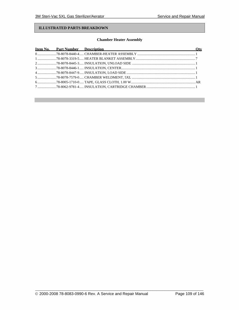
3M Steri-Vac 5XL Gas Sterilizer/Aerator Service and Repair Manual
______________________________________________________________________________________ © 2000-2008 78-8083-0990-6 Rev. A Service and Repair Manual Page 109 of 146
ILLUSTRATED PARTS BREAKDOWN
Chamber Heater Assembly
Item No. Part Number Description Qty 0 .....................78-8078-8440-4..... CHAMBER-HEATER ASSEMBLY ................................................................. 1 1 .....................78-8078-3319-5..... HEATER BLANKET ASSEMBLY................................................................... 7 2 .....................78-8078-8445-3..... INSULATION, UNLOAD SIDE ....................................................................... 1 3 .....................78-8078-8446-1..... INSULATION, CENTER................................................................................... 1 4 .....................78-8078-8447-9..... INSULATION, LOAD SIDE ............................................................................. 1 5 .....................78-8078-7579-0..... CHAMBER WELDMENT, 5XL ....................................................................... 1 6 .....................78-8005-1710-0..... TAPE, GLASS CLOTH, 1.00 W........................................................................AR 7 .....................78-8062-9781-4..... INSULATION, CARTRIDGE CHAMBER....................................................... 1
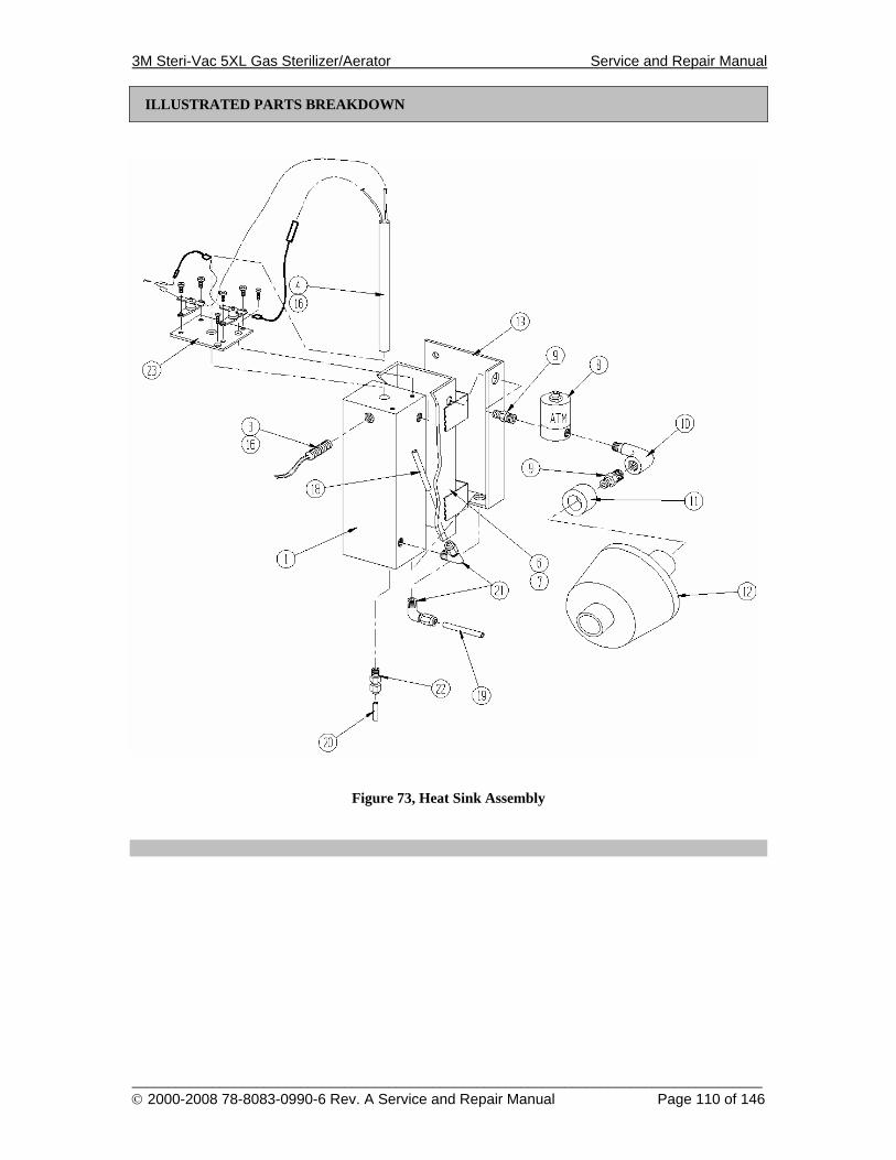
3M Steri-Vac 5XL Gas Sterilizer/Aerator Service and Repair Manual
______________________________________________________________________________________ © 2000-2008 78-8083-0990-6 Rev. A Service and Repair Manual Page 110 of 146
ILLUSTRATED PARTS BREAKDOWN
Figure 73, Heat Sink Assembly
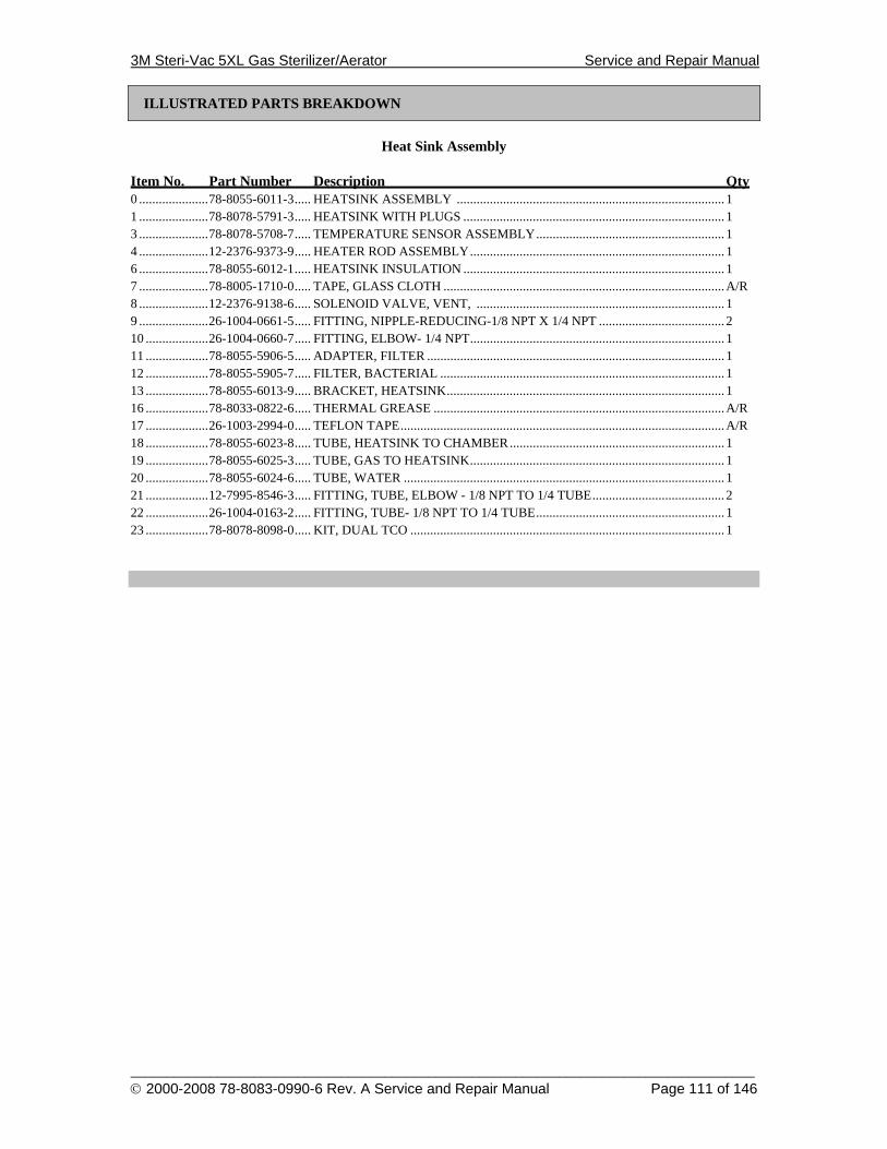
3M Steri-Vac 5XL Gas Sterilizer/Aerator Service and Repair Manual
______________________________________________________________________________________ © 2000-2008 78-8083-0990-6 Rev. A Service and Repair Manual Page 111 of 146
ILLUSTRATED PARTS BREAKDOWN
Heat Sink Assembly
Item No. Part Number Description Qty 0 .....................78-8055-6011-3..... HEATSINK ASSEMBLY ................................................................................. 1 1 .....................78-8078-5791-3..... HEATSINK WITH PLUGS ............................................................................... 1 3 .....................78-8078-5708-7..... TEMPERATURE SENSOR ASSEMBLY......................................................... 1 4 .....................12-2376-9373-9..... HEATER ROD ASSEMBLY............................................................................. 1 6 .....................78-8055-6012-1..... HEATSINK INSULATION ............................................................................... 1 7 .....................78-8005-1710-0..... TAPE, GLASS CLOTH .....................................................................................A/R 8 .....................12-2376-9138-6..... SOLENOID VALVE, VENT, ........................................................................... 1 9 .....................26-1004-0661-5..... FITTING, NIPPLE-REDUCING-1/8 NPT X 1/4 NPT ...................................... 2 10 ...................26-1004-0660-7..... FITTING, ELBOW- 1/4 NPT............................................................................. 1 11 ...................78-8055-5906-5..... ADAPTER, FILTER .......................................................................................... 1 12 ...................78-8055-5905-7..... FILTER, BACTERIAL ...................................................................................... 1 13 ...................78-8055-6013-9..... BRACKET, HEATSINK.................................................................................... 1 16 ...................78-8033-0822-6..... THERMAL GREASE ........................................................................................A/R 17 ...................26-1003-2994-0..... TEFLON TAPE..................................................................................................A/R 18 ...................78-8055-6023-8..... TUBE, HEATSINK TO CHAMBER................................................................. 1 19 ...................78-8055-6025-3..... TUBE, GAS TO HEATSINK............................................................................. 1 20 ...................78-8055-6024-6..... TUBE, WATER ................................................................................................. 1 21 ...................12-7995-8546-3..... FITTING, TUBE, ELBOW - 1/8 NPT TO 1/4 TUBE........................................ 2 22 ...................26-1004-0163-2..... FITTING, TUBE- 1/8 NPT TO 1/4 TUBE......................................................... 1 23 ...................78-8078-8098-0..... KIT, DUAL TCO ............................................................................................... 1
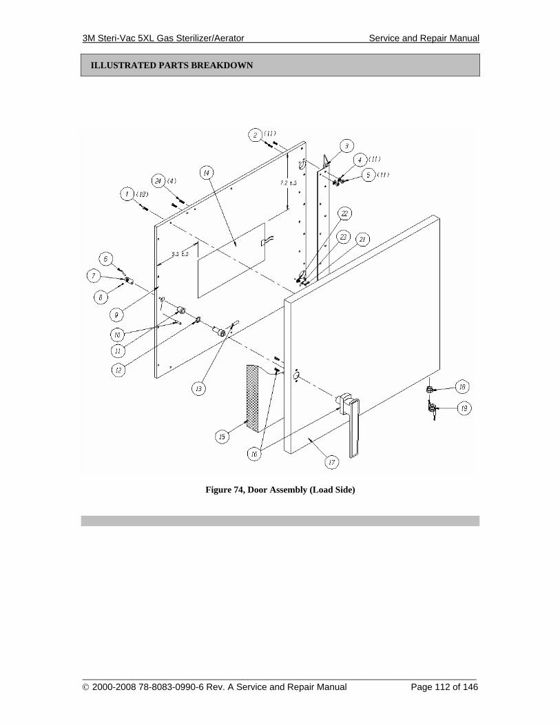
3M Steri-Vac 5XL Gas Sterilizer/Aerator Service and Repair Manual
______________________________________________________________________________________ © 2000-2008 78-8083-0990-6 Rev. A Service and Repair Manual Page 112 of 146
ILLUSTRATED PARTS BREAKDOWN
Figure 74, Door Assembly (Load Side)

3M Steri-Vac 5XL Gas Sterilizer/Aerator Service and Repair Manual
______________________________________________________________________________________ © 2000-2008 78-8083-0990-6 Rev. A Service and Repair Manual Page 113 of 146
ILLUSTRATED PARTS BREAKDOWN
Door Assembly (Load Side)
Item No. Part Number Description Qty 0 .....................78-8078-8481-8..... DOOR ASSEMBLY, LOAD SIDE.................................................................... 1 1 .....................26-1002-5353-8..... SCREW, 8-32 X .625, FLAT HEAD ................................................................. 10 2 .....................70-8000-2823-8..... SCREW, 10-32 X 1.00, FLAT HEAD .............................................................. 11 3 .....................12-2376-5848-4..... HINGE, DOOR .................................................................................................. 1 4 .....................26-1005-4049-6..... WASHER, LOCK, #10....................................................................................... 11 5 .....................70-7023-5420-3..... NUT, 10-32, HEX, ............................................................................................. 11 6 .....................12-2376-3485-7..... PIN, DOOR HANDLE ....................................................................................... 1 7 .....................78-8078-9774-5..... SHAFT, DOOR HANDLE................................................................................. 1 8 .....................78-8005-3303-2..... SCREW, SET, 4-40 X .188 LG. ......................................................................... 1 9 .....................12-2376-5925-0..... PLATE DOOR ................................................................................................... 1 10 ...................18-9261-6200-1..... PIN, SPRING, .188 DIA X .750......................................................................... 1 11 ...................12-2376-4097-9..... BEARING, DOOR ............................................................................................. 1 12 ...................26-1000-8519-5..... WASHER, WAVE ............................................................................................. 1 13 ...................18-9260-8900-6..... PIN, SPRING, .125 DIA X 1.00 LG................................................................... 1 14 ...................78-8078-3319-5..... HEATER BLANKET ASSEMBLY................................................................... 1 15 ...................12-2376-3865-0..... INSULATION.................................................................................................... 1 16 ...................78-8078-9772-9..... HANDLE, DOOR ASSEMBLY ........................................................................ 1 17 ...................12-2376-2792-7..... PANEL, DOOR.................................................................................................. 1 18 ...................26-1004-3140-7..... BUSHING, STRAIN RELIEF............................................................................ 1 19 ...................12-2376-9379-6..... CORD, DOOR HEATER ................................................................................... 1 20 ...................78-8000-8074-5..... LOCTITE ...........................................................................................................AR 21 ...................26-1002-5277-9..... SCREW, 8-32 X .375, PAN HEAD ................................................................... 1 22 ...................26-1004-2053-3..... WASHER, LOCK, #8 ........................................................................................ 1 23 ...................26-1003-4963-3..... TERMINAL, .250 .............................................................................................. 1 24 ...................26-1012-1550-2..... SCREW, 1/4-20 X .50, BUTTON HEAD ......................................................... 4
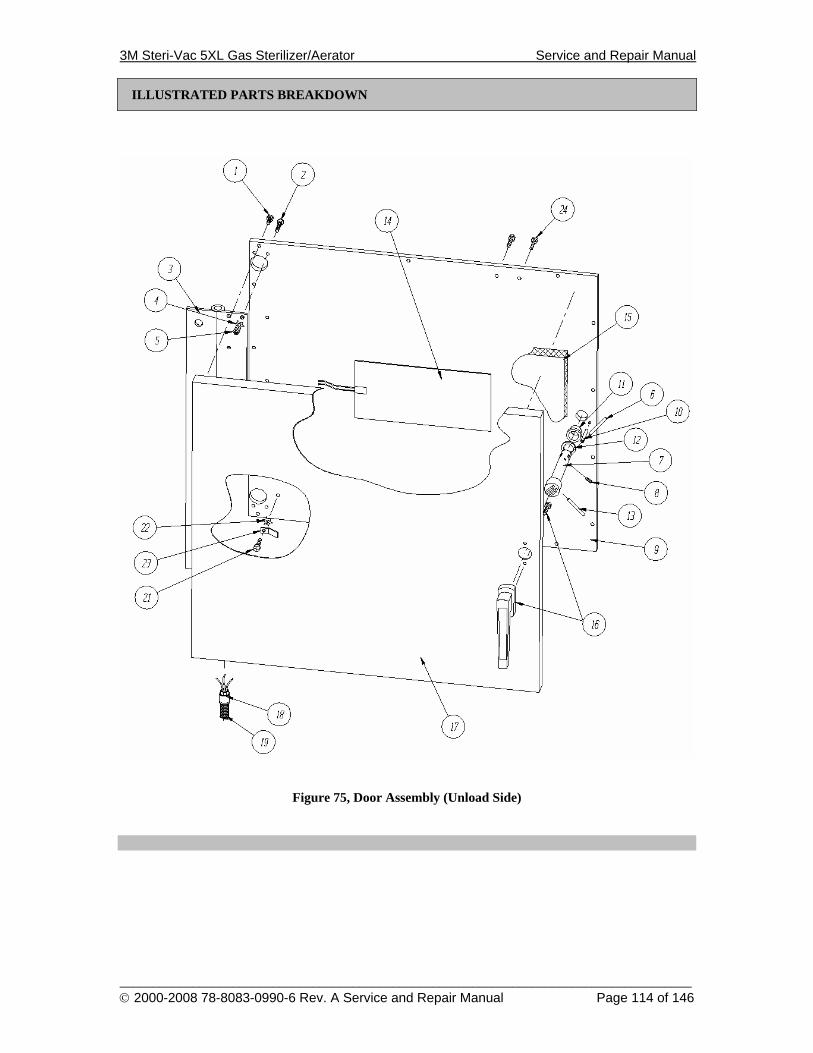
3M Steri-Vac 5XL Gas Sterilizer/Aerator Service and Repair Manual
______________________________________________________________________________________ © 2000-2008 78-8083-0990-6 Rev. A Service and Repair Manual Page 114 of 146
ILLUSTRATED PARTS BREAKDOWN
Figure 75, Door Assembly (Unload Side)
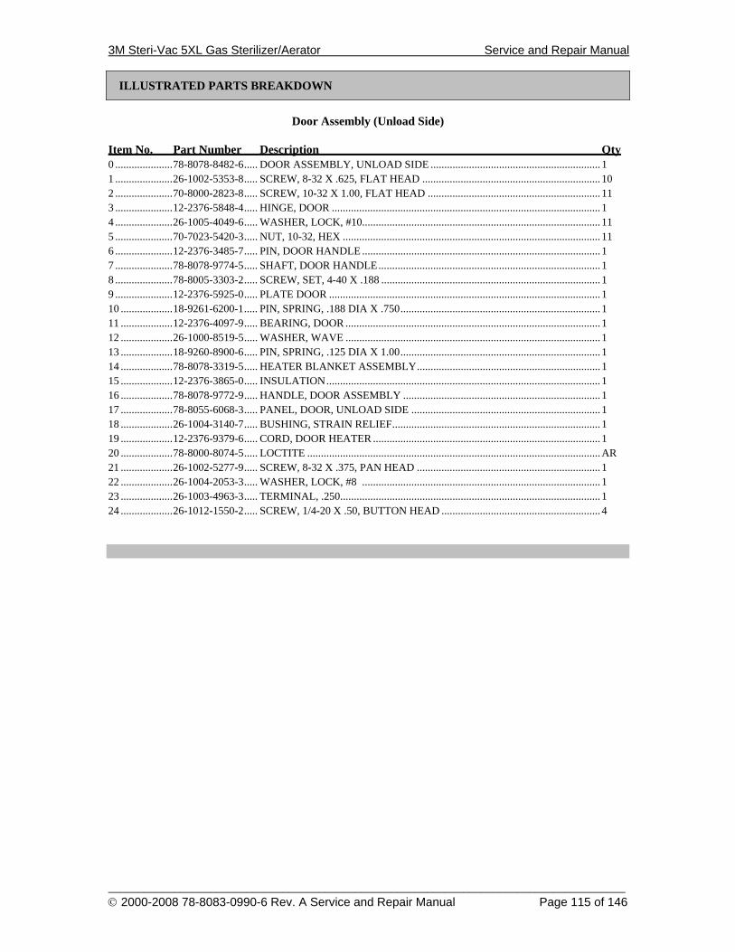
3M Steri-Vac 5XL Gas Sterilizer/Aerator Service and Repair Manual
______________________________________________________________________________________ © 2000-2008 78-8083-0990-6 Rev. A Service and Repair Manual Page 115 of 146
ILLUSTRATED PARTS BREAKDOWN
Door Assembly (Unload Side)
Item No. Part Number Description Qty 0 .....................78-8078-8482-6..... DOOR ASSEMBLY, UNLOAD SIDE .............................................................. 1 1 .....................26-1002-5353-8..... SCREW, 8-32 X .625, FLAT HEAD ................................................................. 10 2 .....................70-8000-2823-8..... SCREW, 10-32 X 1.00, FLAT HEAD ............................................................... 11 3 .....................12-2376-5848-4..... HINGE, DOOR .................................................................................................. 1 4 .....................26-1005-4049-6..... WASHER, LOCK, #10....................................................................................... 11 5 .....................70-7023-5420-3..... NUT, 10-32, HEX .............................................................................................. 11 6 .....................12-2376-3485-7..... PIN, DOOR HANDLE ....................................................................................... 1 7 .....................78-8078-9774-5..... SHAFT, DOOR HANDLE................................................................................. 1 8 .....................78-8005-3303-2..... SCREW, SET, 4-40 X .188 ................................................................................ 1 9 .....................12-2376-5925-0..... PLATE DOOR ................................................................................................... 1 10 ...................18-9261-6200-1..... PIN, SPRING, .188 DIA X .750......................................................................... 1 11 ...................12-2376-4097-9..... BEARING, DOOR ............................................................................................. 1 12 ...................26-1000-8519-5..... WASHER, WAVE ............................................................................................. 1 13 ...................18-9260-8900-6..... PIN, SPRING, .125 DIA X 1.00......................................................................... 1 14 ...................78-8078-3319-5..... HEATER BLANKET ASSEMBLY................................................................... 1 15 ...................12-2376-3865-0..... INSULATION.................................................................................................... 1 16 ...................78-8078-9772-9..... HANDLE, DOOR ASSEMBLY ........................................................................ 1 17 ...................78-8055-6068-3..... PANEL, DOOR, UNLOAD SIDE ..................................................................... 1 18 ...................26-1004-3140-7..... BUSHING, STRAIN RELIEF............................................................................ 1 19 ...................12-2376-9379-6..... CORD, DOOR HEATER ................................................................................... 1 20 ...................78-8000-8074-5..... LOCTITE ...........................................................................................................AR 21 ...................26-1002-5277-9..... SCREW, 8-32 X .375, PAN HEAD ................................................................... 1 22 ...................26-1004-2053-3..... WASHER, LOCK, #8 ....................................................................................... 1 23 ...................26-1003-4963-3..... TERMINAL, .250............................................................................................... 1 24 ...................26-1012-1550-2..... SCREW, 1/4-20 X .50, BUTTON HEAD .......................................................... 4
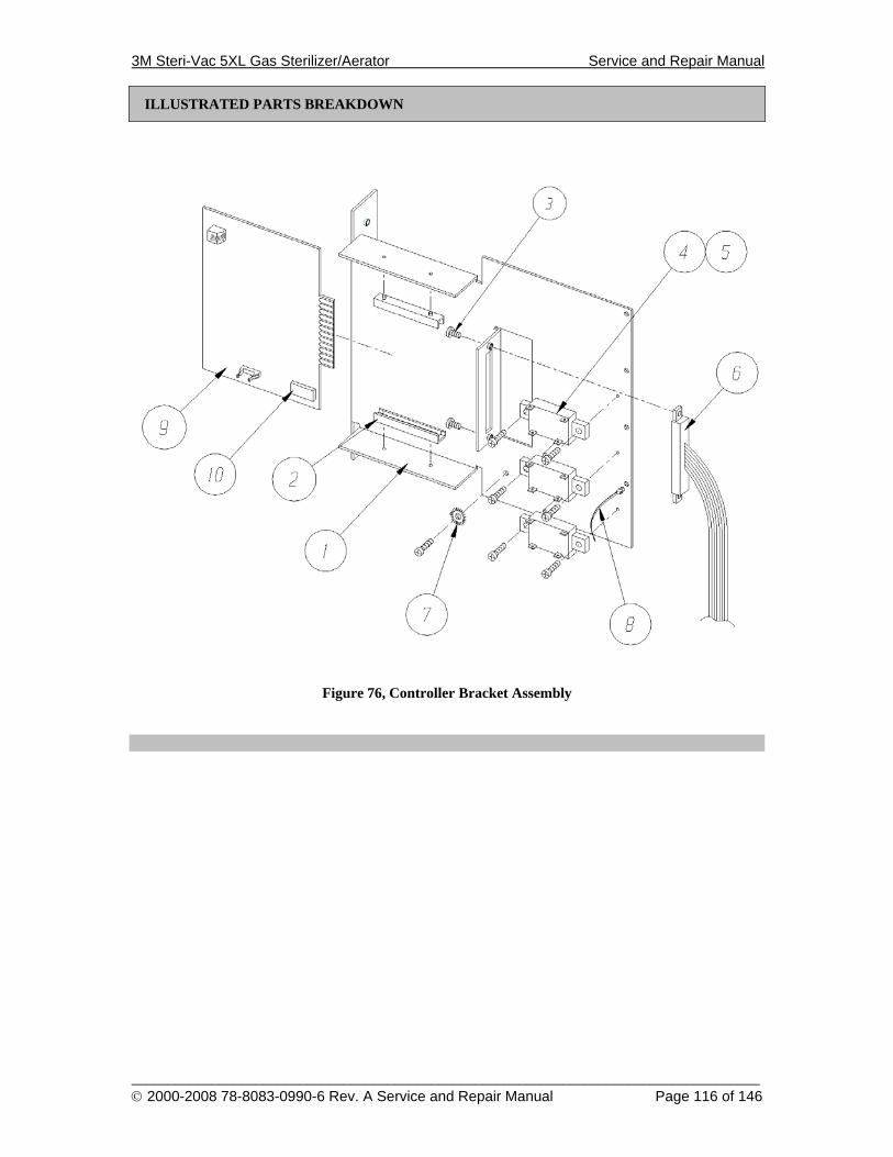
3M Steri-Vac 5XL Gas Sterilizer/Aerator Service and Repair Manual
______________________________________________________________________________________ © 2000-2008 78-8083-0990-6 Rev. A Service and Repair Manual Page 116 of 146
ILLUSTRATED PARTS BREAKDOWN
Figure 76, Controller Bracket Assembly
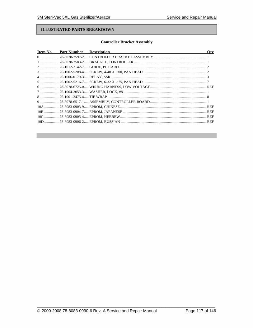
3M Steri-Vac 5XL Gas Sterilizer/Aerator Service and Repair Manual
______________________________________________________________________________________ © 2000-2008 78-8083-0990-6 Rev. A Service and Repair Manual Page 117 of 146
ILLUSTRATED PARTS BREAKDOWN
Controller Bracket Assembly
Item No. Part Number Description Qty 0 .....................78-8078-7597-2..... CONTROLLER BRACKET ASSEMBLY ........................................................ 1 1 .....................78-8078-7583-2..... BRACKET, CONTROLLER ............................................................................. 1 2 .....................26-1012-2142-7..... GUIDE, PC CARD............................................................................................. 2 3 .....................26-1002-5208-4..... SCREW, 4-40 X .500, PAN HEAD ................................................................... 2 4 .....................26-1006-0179-3..... RELAY, SSR...................................................................................................... 3 5 .....................26-1002-5216-7..... SCREW, 6-32 X .375, PAN HEAD ................................................................... 7 6 .....................78-8078-6725-0..... WIRING HARNESS, LOW VOLTAGE............................................................REF 7 .....................26-1004-2053-3..... WASHER, LOCK, #8 ........................................................................................ 1 8 .....................26-1001-2475-4..... TIE WRAP ......................................................................................................... 8 9 .....................78-8078-6517-1..... ASSEMBLY, CONTROLLER BOARD............................................................ 1 10A ................78-8083-0903-9..... EPROM, CHINESE............................................................................................REF 10B ................78-8083-0904-7..... EPROM, JAPANESE.........................................................................................REF 10C ................78-8083-0905-4..... EPROM, HEBREW............................................................................................REF 10D ................78-8083-0906-2..... EPROM, RUSSIAN ...........................................................................................REF
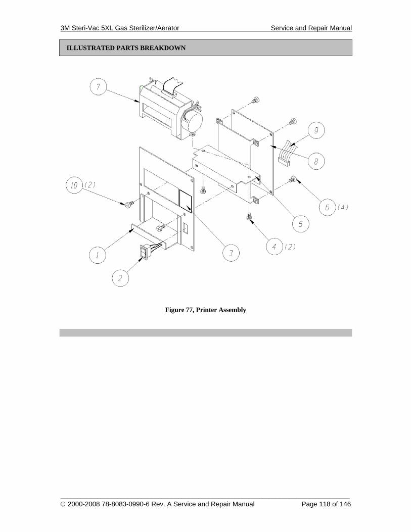
3M Steri-Vac 5XL Gas Sterilizer/Aerator Service and Repair Manual
______________________________________________________________________________________ © 2000-2008 78-8083-0990-6 Rev. A Service and Repair Manual Page 118 of 146
ILLUSTRATED PARTS BREAKDOWN
Figure 77, Printer Assembly
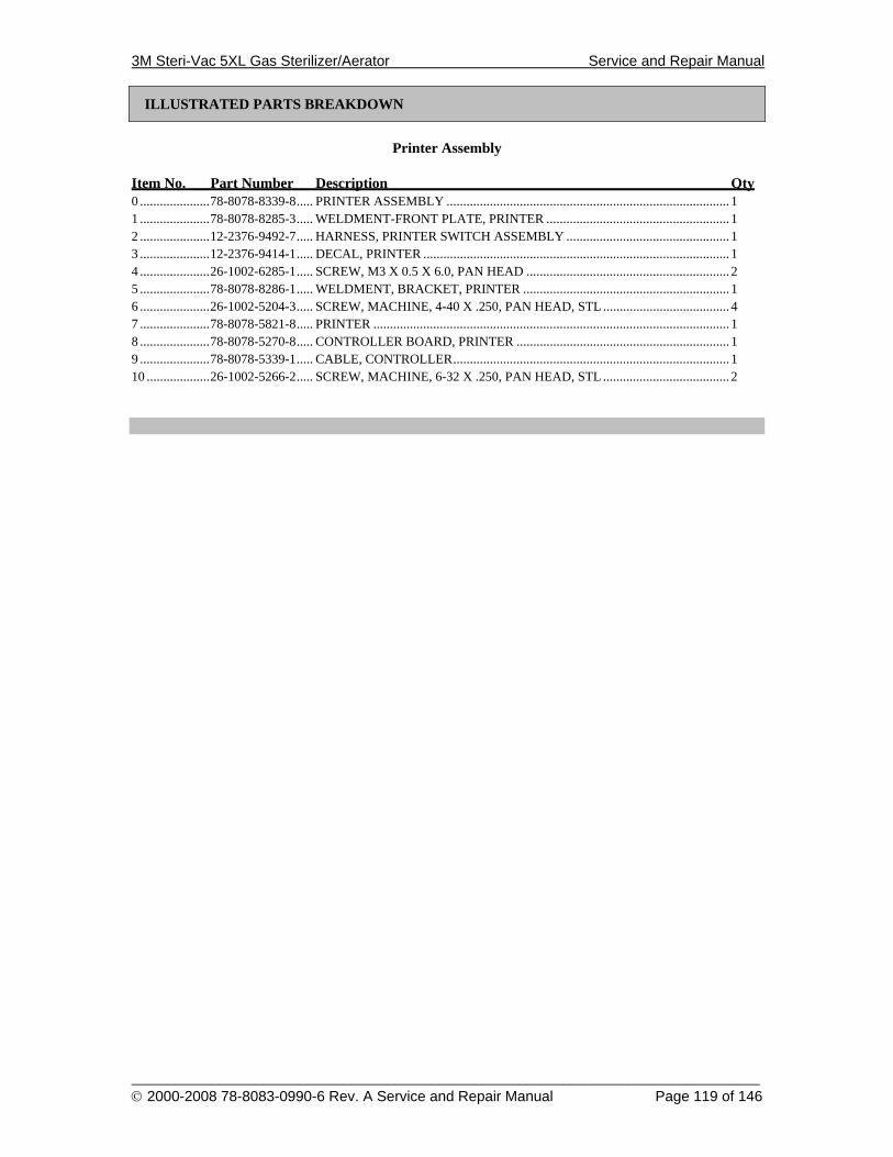
3M Steri-Vac 5XL Gas Sterilizer/Aerator Service and Repair Manual
______________________________________________________________________________________ © 2000-2008 78-8083-0990-6 Rev. A Service and Repair Manual Page 119 of 146
ILLUSTRATED PARTS BREAKDOWN
Printer Assembly
Item No. Part Number Description Qty 0 .....................78-8078-8339-8..... PRINTER ASSEMBLY ..................................................................................... 1 1 .....................78-8078-8285-3..... WELDMENT-FRONT PLATE, PRINTER ....................................................... 1 2 .....................12-2376-9492-7..... HARNESS, PRINTER SWITCH ASSEMBLY ................................................. 1 3 .....................12-2376-9414-1..... DECAL, PRINTER ............................................................................................ 1 4 .....................26-1002-6285-1..... SCREW, M3 X 0.5 X 6.0, PAN HEAD ............................................................. 2 5 .....................78-8078-8286-1..... WELDMENT, BRACKET, PRINTER .............................................................. 1 6 .....................26-1002-5204-3..... SCREW, MACHINE, 4-40 X .250, PAN HEAD, STL ...................................... 4 7 .....................78-8078-5821-8..... PRINTER ........................................................................................................... 1 8 .....................78-8078-5270-8..... CONTROLLER BOARD, PRINTER ................................................................ 1 9 .....................78-8078-5339-1..... CABLE, CONTROLLER................................................................................... 1 10 ...................26-1002-5266-2..... SCREW, MACHINE, 6-32 X .250, PAN HEAD, STL ...................................... 2
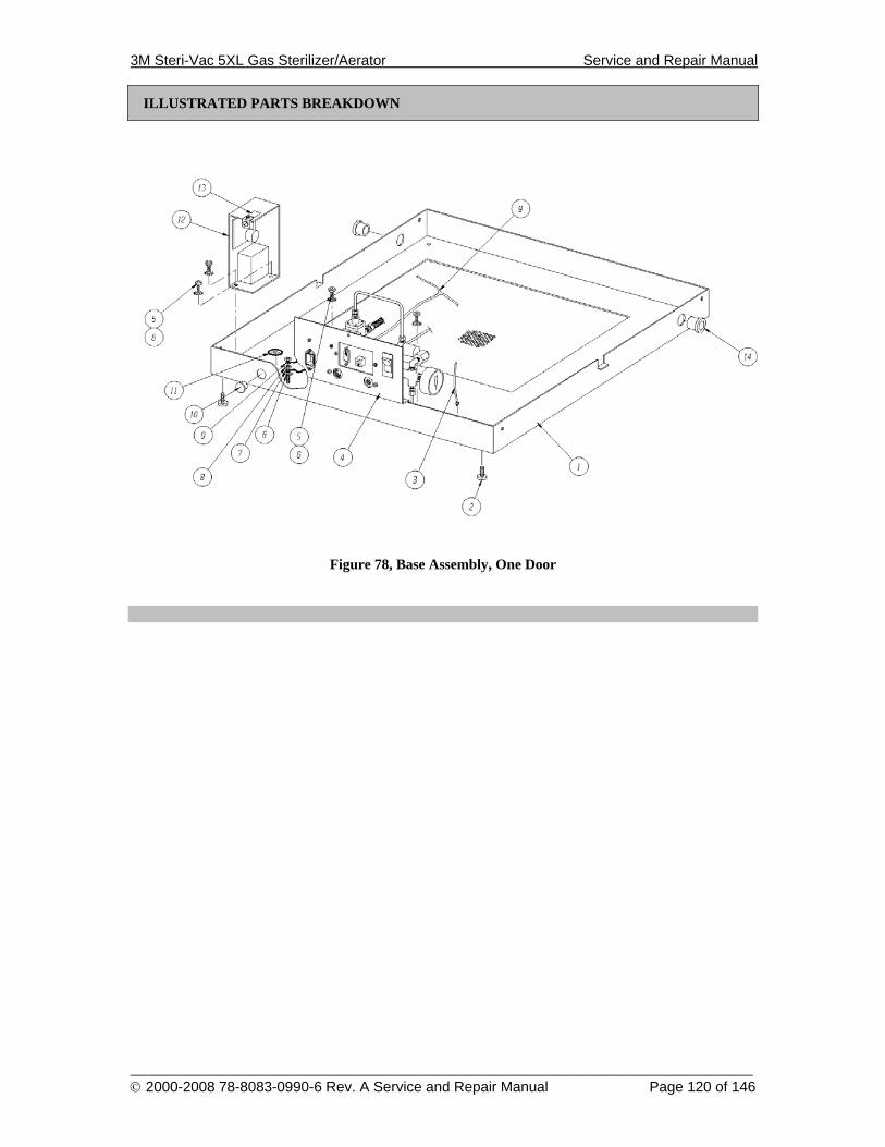
3M Steri-Vac 5XL Gas Sterilizer/Aerator Service and Repair Manual
______________________________________________________________________________________ © 2000-2008 78-8083-0990-6 Rev. A Service and Repair Manual Page 120 of 146
ILLUSTRATED PARTS BREAKDOWN
Figure 78, Base Assembly, One Door
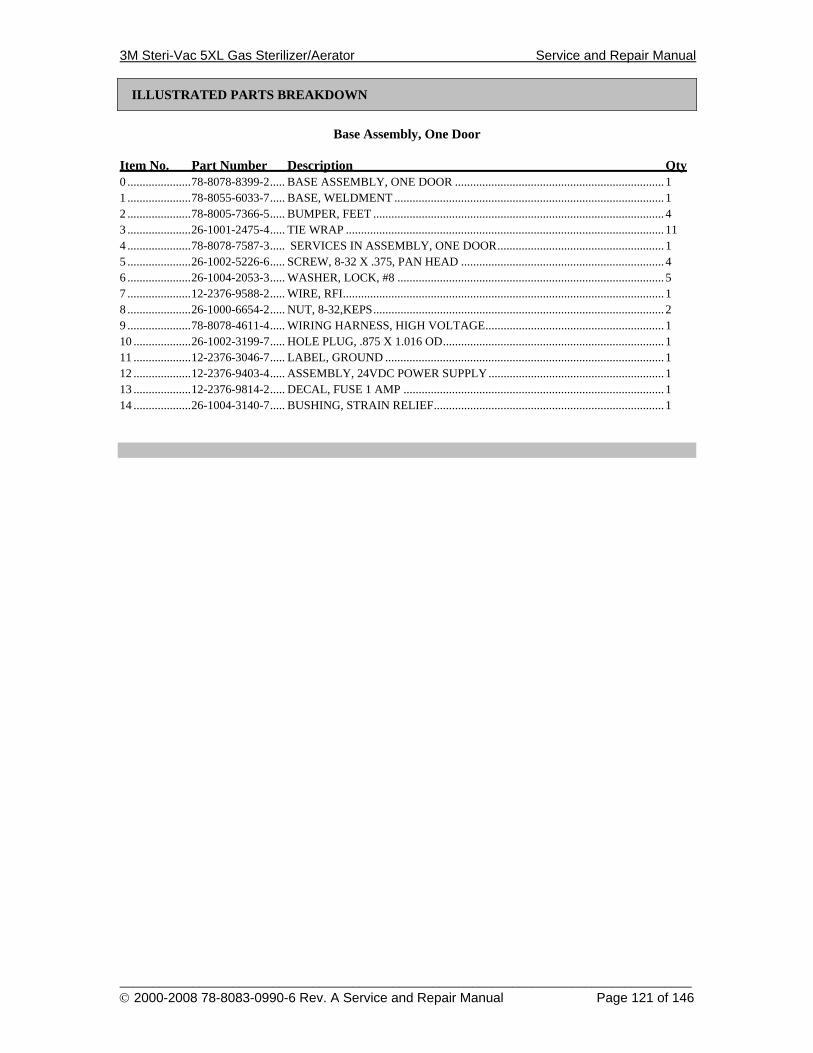
3M Steri-Vac 5XL Gas Sterilizer/Aerator Service and Repair Manual
______________________________________________________________________________________ © 2000-2008 78-8083-0990-6 Rev. A Service and Repair Manual Page 121 of 146
ILLUSTRATED PARTS BREAKDOWN
Base Assembly, One Door
Item No. Part Number Description Qty 0 .....................78-8078-8399-2..... BASE ASSEMBLY, ONE DOOR ..................................................................... 1 1 .....................78-8055-6033-7..... BASE, WELDMENT ......................................................................................... 1 2 .....................78-8005-7366-5..... BUMPER, FEET ................................................................................................ 4 3 .....................26-1001-2475-4..... TIE WRAP ......................................................................................................... 11 4 .....................78-8078-7587-3..... SERVICES IN ASSEMBLY, ONE DOOR....................................................... 1 5 .....................26-1002-5226-6..... SCREW, 8-32 X .375, PAN HEAD ................................................................... 4 6 .....................26-1004-2053-3..... WASHER, LOCK, #8 ........................................................................................ 5 7 .....................12-2376-9588-2..... WIRE, RFI.......................................................................................................... 1 8 .....................26-1000-6654-2..... NUT, 8-32,KEPS................................................................................................ 2 9 .....................78-8078-4611-4..... WIRING HARNESS, HIGH VOLTAGE........................................................... 1 10 ...................26-1002-3199-7..... HOLE PLUG, .875 X 1.016 OD......................................................................... 1 11 ...................12-2376-3046-7..... LABEL, GROUND ............................................................................................ 1 12 ...................12-2376-9403-4..... ASSEMBLY, 24VDC POWER SUPPLY.......................................................... 1 13 ...................12-2376-9814-2..... DECAL, FUSE 1 AMP ...................................................................................... 1 14 ...................26-1004-3140-7..... BUSHING, STRAIN RELIEF............................................................................ 1
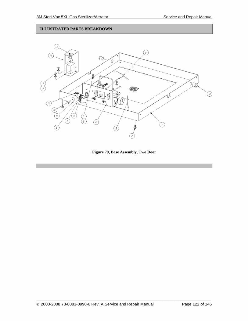
3M Steri-Vac 5XL Gas Sterilizer/Aerator Service and Repair Manual
______________________________________________________________________________________ © 2000-2008 78-8083-0990-6 Rev. A Service and Repair Manual Page 122 of 146
ILLUSTRATED PARTS BREAKDOWN
Figure 79, Base Assembly, Two Door

3M Steri-Vac 5XL Gas Sterilizer/Aerator Service and Repair Manual
______________________________________________________________________________________ © 2000-2008 78-8083-0990-6 Rev. A Service and Repair Manual Page 123 of 146
ILLUSTRATED PARTS BREAKDOWN
Base Assembly, Two Door
Item No. Part Number Description Qty 0 .....................78-8078-8592-2..... BASE ASSEMBLY, TWO DOOR..................................................................... 1 1 .....................78-8055-6033-7..... BASE, WELDMENT ......................................................................................... 1 2 .....................78-8005-7366-5..... BUMPER, FEET ................................................................................................ 4 3 .....................26-1001-2475-4..... TIE WRAP ......................................................................................................... 11 4 .....................78-8078-8593-0..... SERVICES IN ASSEMBLY, TWO DOOR...................................................... 1 5 .....................26-1002-5226-6..... SCREW, 8-32 X .375, PAN HEAD ................................................................... 4 6 .....................26-1004-2053-3..... WASHER, LOCK, #8 ........................................................................................ 5 7 .....................12-2376-9588-2..... WIRE, RFI.......................................................................................................... 1 8 .....................26-1000-6654-2..... NUT, 8-32,KEPS................................................................................................ 2 9 .....................78-8078-4611-4..... WIRING HARNESS, HIGH VOLTAGE........................................................... 1 10 ...................26-1002-3199-7..... HOLE PLUG, .875 X 1.016 OD......................................................................... 1 11 ...................12-2376-3046-7..... LABEL, GROUND ............................................................................................ 1 12 ...................12-2376-9403-4..... ASSEMBLY, 24VDC POWER SUPPLY.......................................................... 1 13 ...................12-2376-9814-2..... DECAL, FUSE 1 AMP ...................................................................................... 1 14 ...................26-1004-3140-7..... BUSHING, STRAIN RELIEF............................................................................ 1
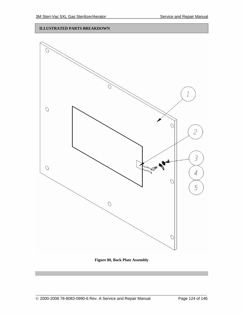
3M Steri-Vac 5XL Gas Sterilizer/Aerator Service and Repair Manual
______________________________________________________________________________________ © 2000-2008 78-8083-0990-6 Rev. A Service and Repair Manual Page 124 of 146
ILLUSTRATED PARTS BREAKDOWN
Figure 80, Back Plate Assembly
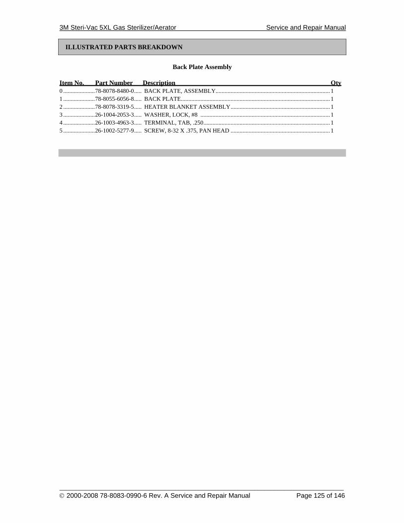
3M Steri-Vac 5XL Gas Sterilizer/Aerator Service and Repair Manual
______________________________________________________________________________________ © 2000-2008 78-8083-0990-6 Rev. A Service and Repair Manual Page 125 of 146
ILLUSTRATED PARTS BREAKDOWN
Back Plate Assembly
Item No. Part Number Description Qty 0 .....................78-8078-8480-0..... BACK PLATE, ASSEMBLY............................................................................ 1 1 .....................78-8055-6056-8..... BACK PLATE................................................................................................... 1 2 .....................78-8078-3319-5..... HEATER BLANKET ASSEMBLY.................................................................. 1 3 .....................26-1004-2053-3..... WASHER, LOCK, #8 ...................................................................................... 1 4 .....................26-1003-4963-3..... TERMINAL, TAB, .250.................................................................................... 1 5 .....................26-1002-5277-9..... SCREW, 8-32 X .375, PAN HEAD .................................................................. 1
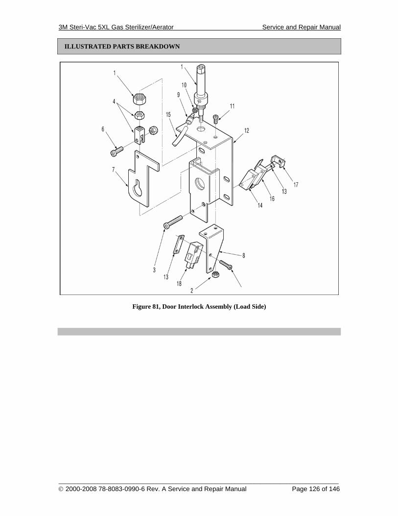
3M Steri-Vac 5XL Gas Sterilizer/Aerator Service and Repair Manual
______________________________________________________________________________________ © 2000-2008 78-8083-0990-6 Rev. A Service and Repair Manual Page 126 of 146
ILLUSTRATED PARTS BREAKDOWN
Figure 81, Door Interlock Assembly (Load Side)
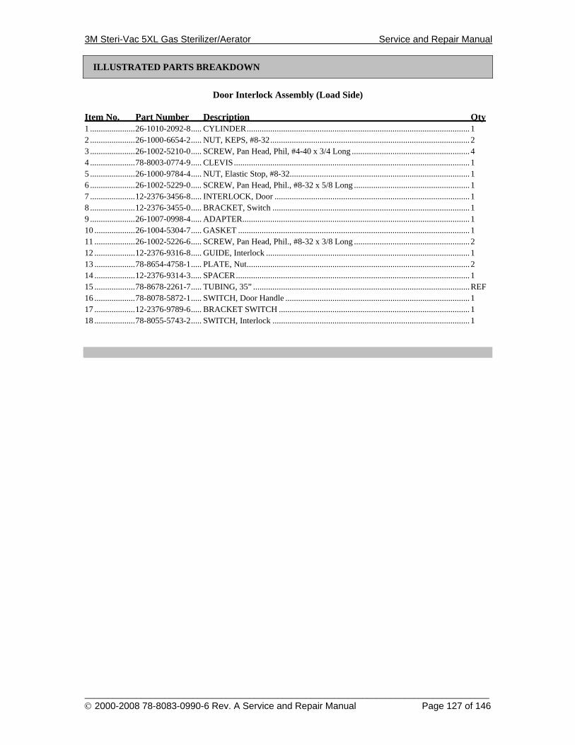
3M Steri-Vac 5XL Gas Sterilizer/Aerator Service and Repair Manual
______________________________________________________________________________________ © 2000-2008 78-8083-0990-6 Rev. A Service and Repair Manual Page 127 of 146
ILLUSTRATED PARTS BREAKDOWN
Door Interlock Assembly (Load Side)
Item No. Part Number Description Qty 1 .....................26-1010-2092-8..... CYLINDER........................................................................................................ 1 2 .....................26-1000-6654-2..... NUT, KEPS, #8-32............................................................................................. 2 3 .....................26-1002-5210-0..... SCREW, Pan Head, Phil, #4-40 x 3/4 Long ....................................................... 4 4 .....................78-8003-0774-9..... CLEVIS.............................................................................................................. 1 5 .....................26-1000-9784-4..... NUT, Elastic Stop, #8-32.................................................................................... 1 6 .....................26-1002-5229-0..... SCREW, Pan Head, Phil., #8-32 x 5/8 Long ...................................................... 1 7 .....................12-2376-3456-8..... INTERLOCK, Door ........................................................................................... 1 8 .....................12-2376-3455-0..... BRACKET, Switch ............................................................................................ 1 9 .....................26-1007-0998-4..... ADAPTER.......................................................................................................... 1 10 ...................26-1004-5304-7..... GASKET ............................................................................................................ 1 11 ...................26-1002-5226-6..... SCREW, Pan Head, Phil., #8-32 x 3/8 Long ...................................................... 2 12 ...................12-2376-9316-8..... GUIDE, Interlock ............................................................................................... 1 13 ...................78-8654-4758-1..... PLATE, Nut........................................................................................................ 2 14 ...................12-2376-9314-3..... SPACER............................................................................................................. 1 15 ...................78-8678-2261-7..... TUBING, 35” .....................................................................................................REF 16 ...................78-8078-5872-1..... SWITCH, Door Handle ...................................................................................... 1 17 ...................12-2376-9789-6..... BRACKET SWITCH ......................................................................................... 1 18 ...................78-8055-5743-2..... SWITCH, Interlock ............................................................................................ 1
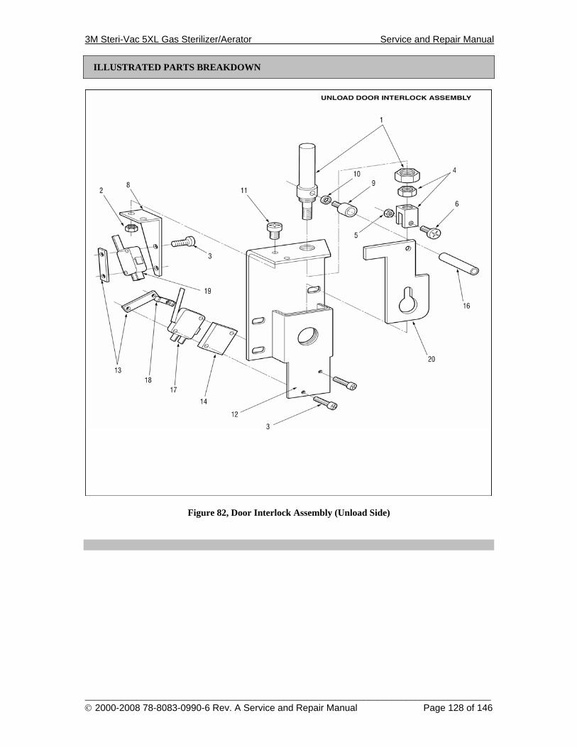
3M Steri-Vac 5XL Gas Sterilizer/Aerator Service and Repair Manual
______________________________________________________________________________________ © 2000-2008 78-8083-0990-6 Rev. A Service and Repair Manual Page 128 of 146
ILLUSTRATED PARTS BREAKDOWN
Figure 82, Door Interlock Assembly (Unload Side)
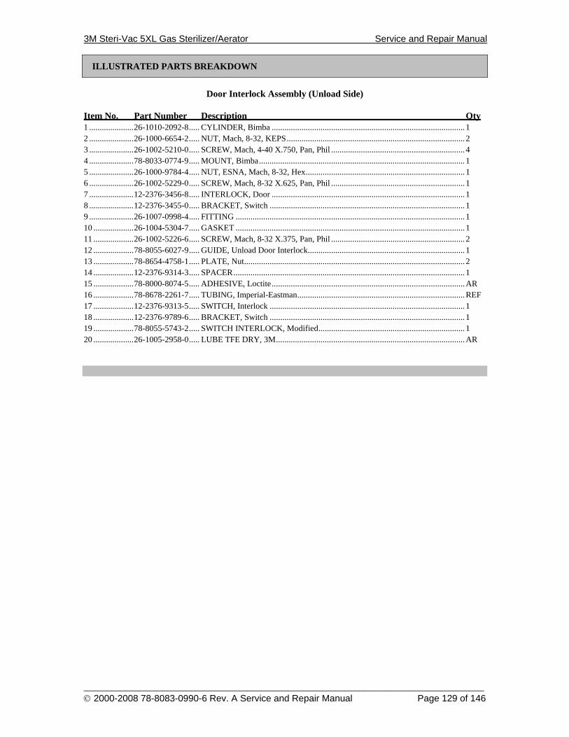
3M Steri-Vac 5XL Gas Sterilizer/Aerator Service and Repair Manual
______________________________________________________________________________________ © 2000-2008 78-8083-0990-6 Rev. A Service and Repair Manual Page 129 of 146
ILLUSTRATED PARTS BREAKDOWN
Door Interlock Assembly (Unload Side)
Item No. Part Number Description Qty 1 .....................26-1010-2092-8..... CYLINDER, Bimba ........................................................................................... 1 2 .....................26-1000-6654-2..... NUT, Mach, 8-32, KEPS.................................................................................... 2 3 .....................26-1002-5210-0..... SCREW, Mach, 4-40 X.750, Pan, Phil ............................................................... 4 4 .....................78-8033-0774-9..... MOUNT, Bimba................................................................................................. 1 5 .....................26-1000-9784-4..... NUT, ESNA, Mach, 8-32, Hex........................................................................... 1 6 .....................26-1002-5229-0..... SCREW, Mach, 8-32 X.625, Pan, Phil ............................................................... 1 7 .....................12-2376-3456-8..... INTERLOCK, Door ........................................................................................... 1 8 .....................12-2376-3455-0..... BRACKET, Switch ............................................................................................ 1 9 .....................26-1007-0998-4..... FITTING ............................................................................................................ 1 10 ...................26-1004-5304-7..... GASKET ............................................................................................................ 1 11 ...................26-1002-5226-6..... SCREW, Mach, 8-32 X.375, Pan, Phil ............................................................... 2 12 ...................78-8055-6027-9..... GUIDE, Unload Door Interlock.......................................................................... 1 13 ...................78-8654-4758-1..... PLATE, Nut........................................................................................................ 2 14 ...................12-2376-9314-3..... SPACER............................................................................................................. 1 15 ...................78-8000-8074-5..... ADHESIVE, Loctite...........................................................................................AR 16 ...................78-8678-2261-7..... TUBING, Imperial-Eastman...............................................................................REF 17 ...................12-2376-9313-5..... SWITCH, Interlock ............................................................................................ 1 18 ...................12-2376-9789-6..... BRACKET, Switch ............................................................................................ 1 19 ...................78-8055-5743-2..... SWITCH INTERLOCK, Modified..................................................................... 1 20 ...................26-1005-2958-0..... LUBE TFE DRY, 3M.........................................................................................AR
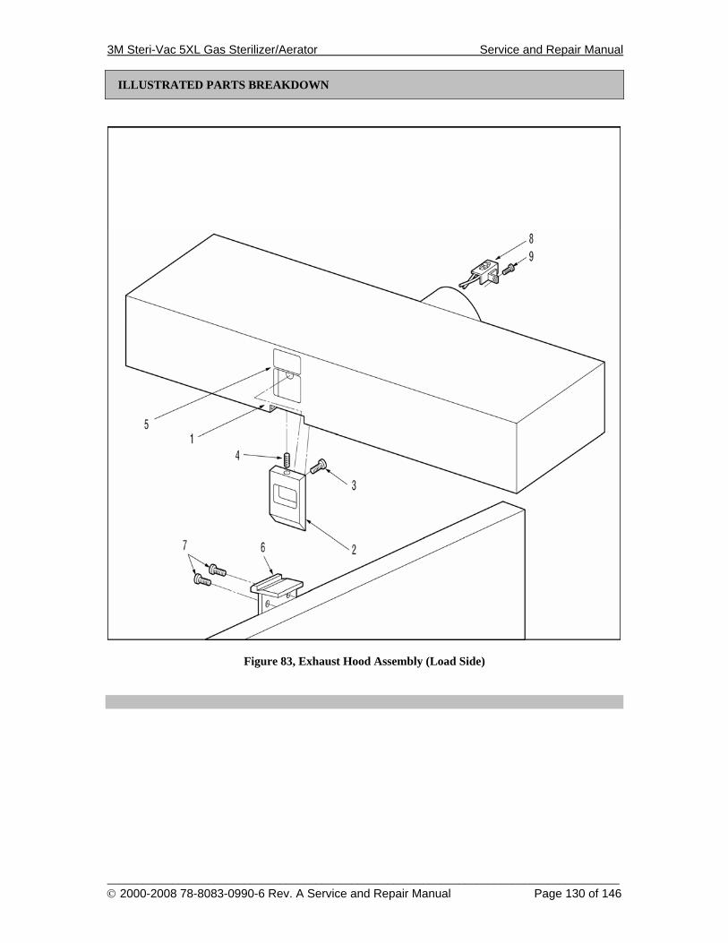
3M Steri-Vac 5XL Gas Sterilizer/Aerator Service and Repair Manual
______________________________________________________________________________________ © 2000-2008 78-8083-0990-6 Rev. A Service and Repair Manual Page 130 of 146
ILLUSTRATED PARTS BREAKDOWN
Figure 83, Exhaust Hood Assembly (Load Side)

3M Steri-Vac 5XL Gas Sterilizer/Aerator Service and Repair Manual
______________________________________________________________________________________ © 2000-2008 78-8083-0990-6 Rev. A Service and Repair Manual Page 131 of 146
ILLUSTRATED PARTS BREAKDOWN
Exhaust Hood Assembly (Load Side)
Item No. Part Number Description Qty 1 .....................78-8055-6059-2..... EXHAUST HOOD, Load Side........................................................................... 1 2 .....................12-2376-5166-1..... LATCH, Slide..................................................................................................... 1 3 .....................26-1001-7289-4..... SCREW, Cap, 8-32 X .250, Skt, Hex ................................................................. 1 4 .....................12-2376-5167-9..... SPRING, Return ................................................................................................. 1 5 .....................12-2376-6210-6..... LABEL, Door Release........................................................................................REF 6 .....................12-2376-6063-9..... CATCH, Latch, Load ......................................................................................... 1 7 .....................18-3104-5815-5..... SCREW, Cap Hex, 1/4-20 X 1/2 ........................................................................ 2 8 .....................78-8063-0467-7..... AIRFLOW SWITCH ASS’Y ............................................................................. 1 9 .....................26-1002-5268-8..... SCREW, Pan Head, Phillips, 6-32 X 3/8............................................................ 1
3M Steri-Vac 5XL Gas Sterilizer/Aerator Service and Repair Manual
______________________________________________________________________________________ © 2000-2008 78-8083-0990-6 Rev. A Service and Repair Manual Page 132 of 146
ILLUSTRATED PARTS BREAKDOWN
Figure 84, Exhaust Hood Assembly (Unload Side)
3M Steri-Vac 5XL Gas Sterilizer/Aerator Service and Repair Manual
______________________________________________________________________________________ © 2000-2008 78-8083-0990-6 Rev. A Service and Repair Manual Page 133 of 146
ILLUSTRATED PARTS BREAKDOWN
Exhaust Hood Assembly (Unload Side)
Item No. Part Number Description Qty 1 .....................78-8055-6061-8..... EXHAUST HOOD, Unload Side ....................................................................... 1 2 .....................78-8055-6038-6..... CATCH, Latch, Unload Side.............................................................................. 1 3 .....................26-1001-7289-4..... SCREW, Cap, 8-32 X .250, Skt, Hex ................................................................. 1 4 .....................12-2376-5167-9..... SPRING, Return ................................................................................................. 1 5 .....................12-2376-6210-6..... LABEL, Door Release........................................................................................REF 6 .....................12-2376-5166-1..... LATCH, Slide..................................................................................................... 1 7 .....................18-3104-5815-5..... SCREW, Cap Hex, 1/4-20 X 1/2 ........................................................................ 2
3M Steri-Vac 5XL Gas Sterilizer/Aerator Service and Repair Manual
______________________________________________________________________________________ © 2000-2008 78-8083-0990-6 Rev. A Service and Repair Manual Page 134 of 146
This page is intentionally blank.
3M Steri-Vac 5XL Gas Sterilizer/Aerator Service and Repair Manual
_________________________________________________________________________________________________________________________________________________________________________________________________________________ © 2000-2008 78-8083-0990-6 Rev. A Service and Repair Manual Page 135 of 146
SCHEMATICS
\3m\6519-7\reva\control.prj
192103114125136147158
DB15
J16
PressureTransducer
End Chamber Heater Blankets
Heatsink Heater
Pin3
Pin4
Pin1
Pin2
Printer Interface BoardSeiko IF5003-01B
CN11
CN1
12345678
DIP2
DIP1
Thermal PrinterSeiko LPT5347A-S576
5V Power Supply
+Out+S-S-Out
Power OneInternational Series
HB5 3/OVP-A
24V Power Supply
+Out+S-S-Out Transformer
Power OneInternational Series
HD24-4.8-A
512 348/10 Amp250 VAC
220-240 VAC Input
Module
PowerEntry
RFIFilter
Thermo-Stat
Mounted On Chamber Wall (65C)
Mounted on Heatsink (105 C)
Display/Keypad Interface Boardc:\3m\board\keypadb\keydisp.sch
192
103
114
125
136
147
158
DB15 KEY1
KEY2
KEY3
KEY0
STOP
KeyPad
LED
78-8078-3987-9
KeyPad/Display
Interface Board
78-8078-4616-3
LCD Display ModuleStanley GMF32024ABTW
5XLe Controller Board78-8078-6518-9
RedBrownBlack
29
30
28
82
61
55
55
55
SSR1
SSR2
SSR3
2423
20
22
20
2220
2420
5
4
4
3
1
2
1
62
8
9
10
11
PowerSwitch
Line
Load 1
2
1
2
22
2024
2020
22
Middle Chamber Heater Blankets
2
+15V
Chamber Pressure
GND 321
J8
Printer Data0
Printer Data1
Printer Data2
Printer Data3
Printer Data4
Printer Data5
Printer Data6
Printer Data7
/Printer D
ata Strobe
/Printer Ack
Printer B
usyP
rinter Error
/Printer Fault
GN
D
1 2 3 4 5 6 7 8 9 10 11 12 13 14 J9
Printer Data0Printer Data1Printer Data2Printer Data3Printer Data4Printer Data5Printer Data6Printer Data7
/Printer Data Strobe
/Printer AckPrinter BusyPrinter Error/Printer FaultGND
1234567891011121314
CN9
Puncture Solenoid
GNDGNDGND+24V+24V
Vcc123456
12
CN4
MPowerSigma1Sigma2Sigma3Sigma4
MPower 123456
123456
MPowerSigma1Sigma2Sigma3Sigma4
MPower
CN6
GNDHS 1
212 GND
HS
CN5
GNDPS
VPS 123
123
GNDPS
VPS
LEDGNDVcc
KEY0KEY1KEY2KEY3STOPGND
NC
987654321
J2
123
J1+24VGND+S
45
VccGND
4321
CN2AC_OUT1
AC_OUT2
FLMM
CL1CL2
Display OnLU0
Vcc
LU1LU2LU3
GND-24V
Contrast VFG
1234567891011121314
CN1
FLMM
CL1CL2
Display OnLU0
Vcc
LU1LU2LU3
GND-24V
Contrast VFG
1234567891011121314
CN1
4321
CN2AC_IN1
AC_IN2
STOPM
KEY3CL1
KEY2CL2
KEY1LU3
KEY0LU2GNDLU1
BacklightLU0FLM
J16STOPMKEY3CL1KEY2CL2KEY1LU3KEY0LU2GNDLU1BacklightLU0FLM
Pin3
Pin4
Pin1
Pin2
Pin3
Pin4
Pin1
Pin2
Thermo-Stat
Transformer
512 341/4 Amp250 VAC
1
2
High Voltage
High Voltage
Low Voltage
Low Voltage
82/Printer Initialization
5922
Unload Door Solenoid25Load Door Solenoid37Water Injection Solenoid
Nitrogen Solenoid
26Vacuum Pump Solenoid78Gas Coming (Abator)63RH Solenoids
Electric Pump Vent Sol.Electric Pump Power
32Vent Solenoid
Puncture Sim Sol. Output
77Cycle Starting (Abator)30Heatsink Heater Output28End Heater Output61Middle Heater Output
Extra I/O
4342
4472
4656
3336
5635
3458562157
38
4764
39
Top
Laye
rBo
ttom
Lay
er
Unload Door ShutUnload Door LatchUnload Door HandleAbatorFailedNitrogen PressureCompressed AirCartridge Pos. PowerCartridge PositionCartridge Pos. GndLoad Door ShutLoad Door LatchLoad Door HandleH2O Detect; PowerH2O DetectH2O Detect; GndAirFlow Detect; PowerAirFlow DetectAirFlow Detect GndAbator ReadyPuncture Pin Position
12345678910111213141516171819202122
ABCDEFHJKLMNPRSTUVWXYZ
NO COMNO COMNO COM
NO COM
NO COMNO COM
OutGndVcc
NC COM
NO COM
J4
2741
3141
5352
48 IS+5V
Middle TemperatureVTC2
123456789101112
VTC4Heatsink Temperature
VTC4Chamber Temperature
GND20
5150
49OutGnd Vcc
End TemperatureVTC3
RHLATCHPOSVcc
7069
68GNDTransmit Data TXD
Receive Data RXD1234
J5 RJ11
J7
2220232420
+24VGND+SVccGND
Prin
ter
3 2 1 J6
Prin
ter
On
GN
D/P
rinte
r Fo
rm F
eed
AM
P 58
3617
-1
Sw
itch
1
AM
P 58
3617
-1
192
103
114
125
136
147
158
Abator Interface Port
72
20
AMP 583617-1
38
77
78
22
24
54
55
Signal GND
Signal GND
Extra I/OExtra 1 SolExtra 2 SolExtra 3 SolFrame Ground
12345678
321J2Ex
tern
al A
udio
Aud
ioV
cc
GN
D
67 FRAME GROUND
Thermo-Stat
3152 13
14 RecorderTemperatureVTC2
NO COM
Receive Data Transmit Data* Digital Ground* Frame Ground *This is the actual order of these two signals. Original schematic has these two signals reversed.
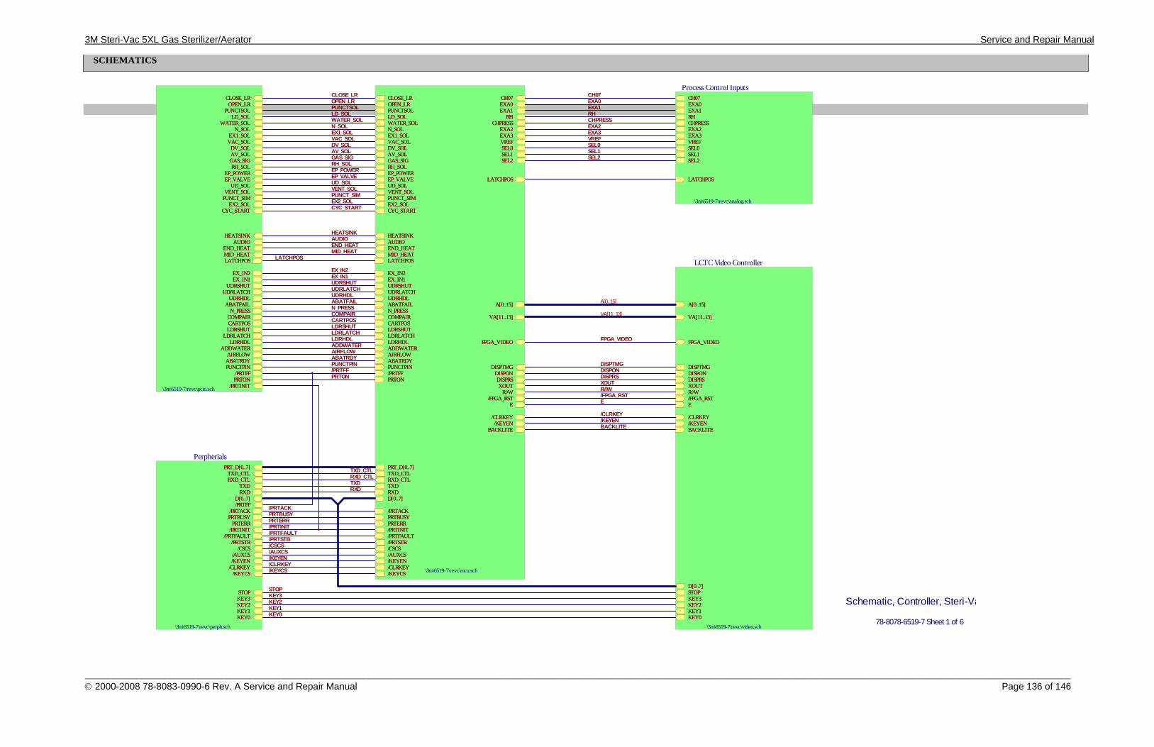
3M Steri-Vac 5XL Gas Sterilizer/Aerator Service and Repair Manual
_________________________________________________________________________________________________________________________________________________________________________________________________________________ © 2000-2008 78-8083-0990-6 Rev. A Service and Repair Manual Page 136 of 146
SCHEMATICS
A[0..15]
D[0..7]STOPKEY3KEY2KEY1KEY0
VA[11..13]
E/FPGA_RSTR//WXOUTDISPRSDISPONDISPTMG
FPGA_VIDEO
/CLRKEY/KEYENBACKLITE
LCTC Video Controller
\3m\6519-7\revc\video.sch
A[0..15]
D[0..7]STOPKEY3KEY2KEY1KEY0
VA[11..13]
E/FPGA_RSTR//WXOUTDISPRSDISPONDISPTMG
FPGA_VIDEO
/CLRKEY/KEYENBACKLITE
A[0..15]
VA[11..13]
D[0..7]
PRT_D[0..7]
TXDRXD
/PRTACKPRTBUSYPRTERR/PRTINIT/PRTFAULT/PRTSTB/CSCS/AUXCS/KEYEN/CLRKEY/KEYCS
PRTON/PRTFFPUNCTPINABATRDYAIRFLOWADDWATERLDRHDLLDRLATCHLDRSHUTCARTPOSCOMPAIRN_PRESSABATFAILUDRHDLUDRLATCHUDRSHUTEX_IN1EX_IN2
CLOSE_LROPEN_LRPUNCTSOLLD_SOLWATER_SOLN_SOLEX1_SOLVAC_SOLDV_SOLAV_SOLGAS_SIGRH_SOLEP_POWEREP_VALVEUD_SOLVENT_SOLPUNCT_SIMEX2_SOLCYC_START
HEATSINKAUDIOEND_HEATMID_HEAT
CH07EXA0EXA1
RHCHPRESS
EXA2EXA3VREFSEL0SEL1SEL2
LATCHPOS
LATCHPOS
DISPTMGDISPONDISPRSXOUT
R//W/FPGA_RST
E
FPGA_VIDEO
/CLRKEY/KEYEN
BACKLITE
TXD_CTLRXD_CTL
\3m\6519-7\revc\mcu.sch
A[0..15]
VA[11..13]
D[0..7]
PRT_D[0..7]
TXDRXD
/PRTACKPRTBUSYPRTERR/PRTINIT/PRTFAULT/PRTSTB/CSCS/AUXCS/KEYEN/CLRKEY/KEYCS
PRTON/PRTFFPUNCTPINABATRDYAIRFLOWADDWATERLDRHDLLDRLATCHLDRSHUTCARTPOSCOMPAIRN_PRESSABATFAILUDRHDLUDRLATCHUDRSHUTEX_IN1EX_IN2
CLOSE_LROPEN_LRPUNCTSOLLD_SOLWATER_SOLN_SOLEX1_SOLVAC_SOLDV_SOLAV_SOLGAS_SIGRH_SOLEP_POWEREP_VALVEUD_SOLVENT_SOLPUNCT_SIMEX2_SOLCYC_START
HEATSINKAUDIOEND_HEATMID_HEAT
CH07EXA0EXA1
RHCHPRESS
EXA2EXA3VREFSEL0SEL1SEL2
LATCHPOS
LATCHPOS
DISPTMGDISPONDISPRSXOUT
R//W/FPGA_RST
E
FPGA_VIDEO
/CLRKEY/KEYEN
BACKLITE
TXD_CTLRXD_CTL
/PRTINIT
LATCHPOS
EX_IN2EX_IN1
UDRSHUTUDRLATCH
UDRHDLABATFAIL
N_PRESSCOMPAIRCARTPOSLDRSHUT
LDRLATCHLDRHDL
ADDWATERAIRFLOWABATRDYPUNCTPIN
/PRTFFPRTON
CLOSE_LROPEN_LR
PUNCTSOLLD_SOL
WATER_SOLN_SOL
EX1_SOLVAC_SOL
DV_SOLAV_SOLGAS_SIGRH_SOL
EP_POWEREP_VALVE
UD_SOLVENT_SOL
PUNCT_SIMEX2_SOL
CYC_START
HEATSINKAUDIO
END_HEATMID_HEAT
\3m\6519-7\revc\pcio.sch /PRTINIT
LATCHPOS
EX_IN2EX_IN1
UDRSHUTUDRLATCH
UDRHDLABATFAIL
N_PRESSCOMPAIRCARTPOSLDRSHUT
LDRLATCHLDRHDL
ADDWATERAIRFLOWABATRDYPUNCTPIN
/PRTFFPRTON
CLOSE_LROPEN_LR
PUNCTSOLLD_SOL
WATER_SOLN_SOL
EX1_SOLVAC_SOL
DV_SOLAV_SOLGAS_SIGRH_SOL
EP_POWEREP_VALVE
UD_SOLVENT_SOL
PUNCT_SIMEX2_SOL
CYC_START
HEATSINKAUDIO
END_HEATMID_HEAT
D[0..7]
PRT_D[0..7]
TXDRXD
/PRTFF/PRTACKPRTBUSY
PRTERR/PRTINIT
/PRTFAULT/PRTSTB
/CSCS/AUXCS/KEYEN
/CLRKEY/KEYCS
STOPKEY3KEY2KEY1KEY0
TXD_CTLRXD_CTL
Perpherials
\3m\6519-7\revc\perph.sch
D[0..7]
PRT_D[0..7]
TXDRXD
/PRTFF/PRTACKPRTBUSY
PRTERR/PRTINIT
/PRTFAULT/PRTSTB
/CSCS/AUXCS/KEYEN
/CLRKEY/KEYCS
STOPKEY3KEY2KEY1KEY0
TXD_CTLRXD_CTL
/PRTACKPRTBUSYPRTERR/PRTINIT/PRTFAULT/PRTSTB
DISPTMG
DISPRSXOUTR//W/FPGA_RSTE
/CSCS/AUXCS
/CLRKEY/KEYCS
STOP
KEY0KEY1KEY2KEY3
TXDRXD
CH07EXA0EXA1RHCHPRESSEXA2EXA3VREFSEL0SEL1SEL2
LATCHPOS
Process Control Inputs
\3m\6519-7\revc\analog.sch
CH07EXA0EXA1RHCHPRESSEXA2EXA3VREFSEL0SEL1SEL2
LATCHPOS
CH07EXA0EXA1
EXA2EXA3VREF
RHCHPRESS
PRTON/PRTFFPUNCTPINABATRDYAIRFLOWADDWATERLDRHDLLDRLATCHLDRSHUTCARTPOSCOMPAIRN_PRESSABATFAILUDRHDLUDRLATCHUDRSHUTEX_IN1EX_IN2
MID_HEATEND_HEATAUDIOHEATSINK
CYC_STARTEX2_SOLPUNCT_SIMVENT_SOLUD_SOLEP_VALVEEP_POWERRH_SOLGAS_SIGAV_SOLDV_SOLVAC_SOLEX1_SOLN_SOLWATER_SOLLD_SOLPUNCTSOLOPEN_LRCLOSE_LR
LATCHPOS
/KEYEN
DISPON
FPGA_VIDEO
SEL0SEL1SEL2
Schematic, Controller, Steri-Va
78-8078-6519-7 Sheet 1 of 6
A[0..15]
VA[11..13]
/CLRKEY/KEYENBACKLITE
TXD_CTLRXD_CTL
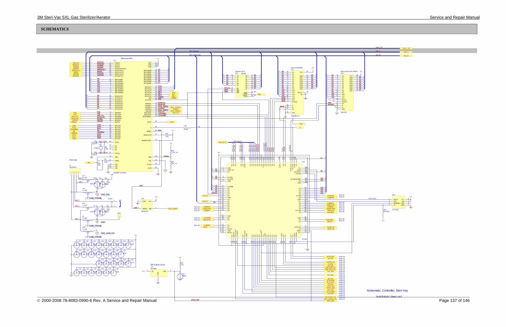
3M Steri-Vac 5XL Gas Sterilizer/Aerator Service and Repair Manual
_________________________________________________________________________________________________________________________________________________________________________________________________________________ © 2000-2008 78-8083-0990-6 Rev. A Service and Repair Manual Page 137 of 146
SCHEMATICS
CH07EXA0
LEAKPRESRH
CHPRESSEXA2EXA3VREF
A0A1A2A3A4A5A6A7A8A9A10A11
D0D1D2D3D4D5D6D7
A0A1A2A3A4A5A6A7
A8A9A10A11A12A13A14A15
D0D1D2D3D4D5D6D7
A0A1A2A3A4A5A6A7A8A9A10A11A12A13EA14EA15
D0D1D2D3D4D5D6D7
Vcc
Vcc
D0D1D2D3D4D5D6D7
A0A1A2A3A4A5
/RST
TXDRXD
DISPTMG
LATCHRESLATCHSET
R//W
/CLRKEY
VA11VA12
Vcc
A12
VA13SEL0SEL1
Vcc
Y1
12 MHz
A010
A19
A28
A37
A46
A55
D0 11
D1 12
D2 13
D3 15
D4 16
D5 17
D6 18
D7 19CE20
OE22
WE27 SQW 23
INTA 1
INTB 26
U27 DS1286
R610M
Vcc
/PRTACKPRTBUSYPRTERR/PRTINIT/PRTFAULT/PRTFF/PRTSTB
SEL2
A012
A111
A210
A39
A48
A57
A66
A75
A827
A926
A1023
A1125
A124
A1328
A1429
A153
NC/A162
VCC 32
DQ0 13
DQ1 14
DQ2 15
DQ3 17
DQ4 18
DQ5 19
DQ6 20
DQ7 21
/E22
/G24
/W31
VSS16
NC/A17 30
NC 1
U23
TMS29F512-C
BANKA14
/EEOE
A010
A19
A28
A37
A46
A55
A64
A73
A825
A924
A1021
A1123
A122
E2/A1326
NC/A141
/W27
/E20
/G22
VSS14
VCC 28
DQ0 11
DQ1 12
DQ2 13
DQ3 15
DQ4 16
DQ5 17
DQ6 18
DQ7 19
U24
DS1225D
Vcc
E
DISPTMG
/RTCCS
SEL0SEL1SEL2
XOUT
/CLRKEY
/PRTACKPRTBUSYPRTERR/PRTINIT
/PRTFAULT/PRTFF
/PRTSTB
DISPRSDISPRS
R//W
RXDTXD
/KEYEN
CH07EXA0EXA1RHCHPRESSEXA2EXA3VREF
Realtime Clock Battery Backed NV-SRAM
External EEPROM
/RST
PA0/IC31
PA1/IC284
PA2/IC183
PA3/IC4/OC5/OC182
PA4/OC4/OC181
PA5/OC3/OC180
PA6/OC2/OC179
PA7/PAI/OC178
PB0/ADDR811
PB1/ADDR910
PB2/ADDR109
PB3/ADDR118
PB4/ADDR127
PB5/ADDR136
PB6/ADDR145
PB7/ADDR154
PC0/DATA055
PC1/DATA156
PC2/DATA257
PC3/DATA358
PC4/DATA459
PC5/DATA560
PC6/DATA661
PC7/DATA762
PD0/RXD72
PD1/TXD73
PD2/MISO74
PD3/MOSI75
PD4/SCK76
PD5//SS77
PE0/AN042
PE1/AN141
PE2/AN240
PE3/AN339
PE4/AN438
PE5/AN537
PE6/AN636
PE7/AN735
XTAL68
NC20
NC22
NC25
EXTAL67
/IRQ54
/XIRQ21
VSS3
VSS24
VSS63 AVSS 45
AVDD 34
VRL 43
VRH 44
VDD 2
VDD 23
VDD 64
PF0/ADDR0 53
PF1/ADDR1 52
PF2/ADDR2 51
PF3/ADDR3 50
PF4/ADDR4 49
PF5/ADDR5 48
PF6/ADDR6 47
PF7/ADDR7 46
PG0/XA13 33
PG1/XA14 32
PG2/XA15 31
PG3/XA16 30
PG4/XA17 29
PG5/XA18 28
PG6 27
PG7/R//W 26
PH0/PW1 12
PH1/PW2 13
PH2/PW3 14
PH3/PW4 15
PH4/CSI0 16
PH5/CSGP1 17
PH6/CSGP2 18
PH7/CSPROG 19
XOUT 66
E 65
/RESET 69
MODA//LIR 71
MODB/VSTBY 70
U2
MC68HC11K1CFN3
/R/W
Vcc
R261.37K .1%
R2710K .1%
Vcc
4.4Volts
TXD_CTL TXD_CTL
Vcc
/KEYEN
MCU Address Bus
MCU Data Bus
NC
NC
R284.7K
FPGA_VIDEO1
RXD_CTL RXD_CTL
BANKA15
BACKLITE BACKLITE
/RAMOE
Microcontroller
EA16
Vcc
DISPON DISPON
FPGA_VIDEO2
/IRQ
/IRQ
DATA1
CLK2
OE/RESET3
CE4 GND 5CEO 6Vpp 7Vcc 8
BX1
XC1765D
Vcc
CLOSE_LROPEN_LR
LD_SOL
WATER_SOLN_SOL
EX2_SOL
VAC_SOL
EX3_SOL
GAS_SIG
RH_SOLEP_POWEREP_VALVE
UD_SOLVENT_SOLPUNCT_SIM
EX1_SOLCYC_START
EXT_AUDIO_CTL
END_HTR_CTLMID_HTR_CTL
A7
A8
A9
A10A11
A12A13A14A15
D0D1D2D3
D4D5
D6D7
PRTONPUNCTPIN
ABATRDYAIRFLOW
ADDWATERLDRHDL
LDRLATCHLDRSHUT
CARTPOSCOMPAIR
/AUXCS
PUNCTSOL
/KEYCS
HEATSINK_CTL
PCO1, D0PCO1, D1
PCO1, D3PCO1, D4PCO1, D5
PCO2, D0PCO2, D1PCO2, D2
PCO3, D4
PCO2, D4PCO2, D5PCO2, D6PCO2, D7PCO3, D0PCO3, D1PCO3, D2PCO3, D3
PCO3, D5PCO3, D6PCO3, D7
PCO1, D6PCO1, D7
PCO1, D2
PCO2, D3
PCI1, D7PCI1, D6
PCI1, D5PCI1, D4PCI1, D3PCI1, D2PCI1, D1PCI1, D0
PCI2, D6PCI2, D7
/RST
FPGA Reset Circuit
Vcc
/FPGA_RST /FPGA_RST
FPGA_VIDEO1
E
R//W
R//W
BA
NKA
15B
AN
KA14
/R/W
EA
16E
A15
EA
14
/EE
OE
/RAM
OE
LATC
HSE
TLA
TCH
RES
ESchematic, Controller, Steri-Vac
78-8078-6519-7 Sheet 2 of 6
PRT_D[0..7]
D[0..7]D[0..7]
A[0..15]A[0..15]
VA[11..13]VA[11..13]
PRT_D[0..7]
PR
T_D
0P
RT_
D1
PR
T_D
2P
RT_
D3
PR
T_D
4P
RT_
D5
PR
T_D
6P
RT_
D7
C7
0.1uF
C8
0.1uF
C9
0.1uF
C10
0.1uF
C11
0.1uF
C12
0.1uF
C13
0.1uF
C14
0.1uF
C15
0.1uF
C16
0.1uF
C17
0.1uF
C18
0.1uF
C19
0.1uF
C20
0.1uF
C21
0.1uF
C26
0.1uF
C27
0.1uF
C28
0.1uF
C29
0.1uF
C30
0.1uF
C31
0.1uF
C32
0.1uF
C33
0.1uF
C34
0.1uF
C35
0.1uF
C36
0.1uF
R5
4.7K
R13
4.7K
Vcc
R354.7K
C37100uF
N_PRESS
ABATFAIL
UDRHDLUDRLATCHUDRSHUT
LATCHPOS
/RTCCS
PCI2, D5
PCI2, D4
PCI2, D2PCI2, D1PCI2, D0
PCI2, D3
/CSCS
Vcc
FPGA_VIDEO2
GND1
GCK1-I/O2
I/O3
I/O-TD16
I/O-TCK7
GND8
I/O-TMS11
I/O12
I/O13
I/O14
I/O16
GND17
Vcc18
I/O19
I/O20
I/O21
I/O22
I/O23
I/O24
GND27
I/O28
I/O29
I/O32
GND35
M0-I/O36V
cc37
M2-
I/O
38
GC
K2-
I/O
39
I/O
-HD
C40
I/O
43
I/O
-LD
C44
GN
D45
I/O
48
I/O
49
I/O
51
I/O
52
I/O
-IN
IT53
Vcc
54
GN
D55
I/O
56
I/O
57
I/O
58
I/O
59
I/O
60
I/O
61
GN
D64
I/O
65
I/O
66
I/O
69
I/O
70
GN
D71
DO
NE
72
Vcc 73PROG 74I/O 75GCK3-I/O 76
I/O 80
I/O 79
GND 81
I/O 84I/O-/CS0 85
I/O 88I/O 89Vcc 90GND 91I/O 92I/O-/RS 93
I/O 96I/O 97
GND 100
I/O-/BUSY/RDY 102
I/O-DIN 105I/O-DOUT 106CCLK 107Vcc 108
I/O
-/W
S11
1G
CK
4-I/
O11
2
I/O
115
I/O
116
GN
D11
8
I/O
121
I/O
123
I/O
124
I/O
126
GN
D12
7Vc
c12
8I/
O12
9
I/O
133
I/O
134
I/O
130
I/O
131
GN
D13
7I/
O13
8I/
O13
9
I/O
132
I/O
142
I/O
143
Vcc
144
I/O15
I/O33
M1-I/O34
I/O
50
I/O 86I/O 87
I/O 94I/O 95
I/O 101
I/O
122
I/O
125
I/O
109
GN
D11
0
U14
XC5202
1 2 3 4 5
J7HEADER 5
Power Input
1
2
JP1Jumper
+24V
C60
22uF 35V
C62
.01uF
C2
22uF 35V
C4
.01uF
Vcc
15M_1
15M_2
15M_3
15M_1
15M_4
U49
Ferrite
R//W
C3
1uF
C61
1uF
MCU_XTAL
MCU_EXTAL
C522pF
C622pF
3U17T_CAP
3U15T_CAP
3U16T_CAP
3U1T_CAP
3U18T_CAP
GND_ANALOG
GND_SOL
GND
1
TP13
GND_FRAME
GND_FRAME
GND_FRAME
FPGA_DONE R32470 Ohm
Vcc
IN2 /RST 3
GN
D1
U11MC34064
DATA_BX1
VCC 2
/MR 3/RESET4
GND1U10
MAX6314
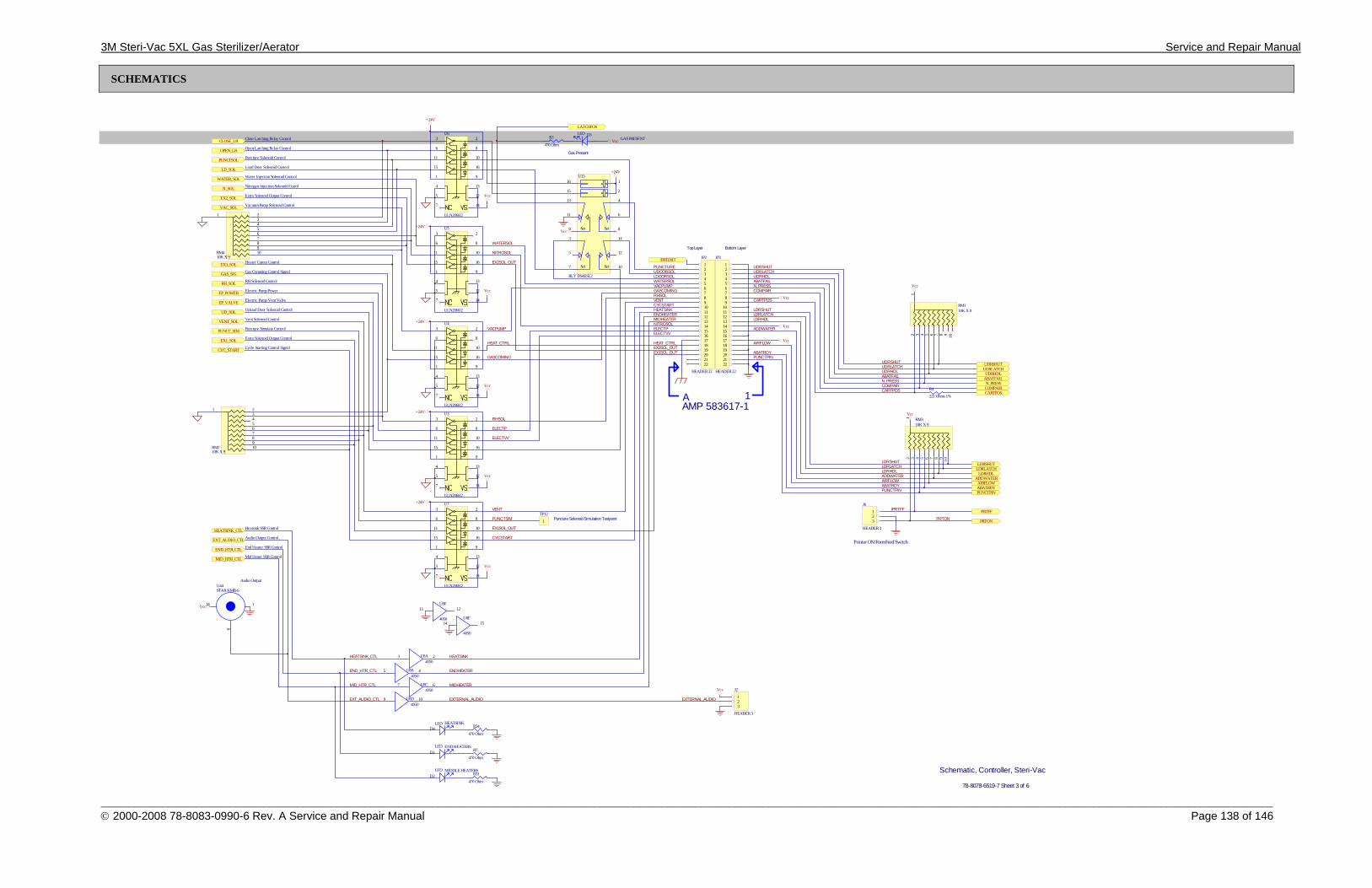
3M Steri-Vac 5XL Gas Sterilizer/Aerator Service and Repair Manual
_________________________________________________________________________________________________________________________________________________________________________________________________________________ © 2000-2008 78-8083-0990-6 Rev. A Service and Repair Manual Page 138 of 146
SCHEMATICS
LATCHPOS
END HEATERS
MIDDLE HEATERS
GAS PRESENT
+24V
D1LED
D2LED
D3LED
3
6
11
15
2
8
10
16
1 9
13
12
4
5
7 14
U3
ULN2068/2
+24V
+24V
+24V
+24V
Vcc
Vcc
Vcc
Vcc
Vcc
MIDHEATER
ENDHEATER
PUNCTURE
HEATSINK
+24V
Vcc
GASCOMING
PUNCTSIM
EX1SOL_OUT
CYCSTART
VENT
ELECTP
RHSOL
ELECTVV
UDOORSOL
VACPUMP
HEAT_CTRL
EX2SOL_OUT
NITROSOL
WATERSOL
LDOORSOL
D4LED
1
8
14
U44STAR KMB-6
Vcc
Vacuum Pump Solenoid Control
RH Solenoid Control
Electric Pump Power
Electric Pump Vent Valve
Unload Door Solenoid Control
Vent Solenoid Control
Puncture Simulate Control
Extra Solenoid Output Control
Cycle Starting Control Signal
Heatsink SSR Control
End Heater SSR Control
Mid Heaer SSR Control
Audio Output Control
Extra Solenoid Output Control
Nitrogen Injection Solenoid Cotrol
Water Injection Solenoid Control
Load Door Solenoid Control
Puncture Solenoid Control
Open Latching Relay Control
Close Latching Relay Control
Audio Output
HEATSINK
R3
470 OhmVcc
16
15
13
11
9
1
2
4
6
8Set Set
14
12
10
3
5
7 Set Set
U13
RLY DS4ESL2
R7
470 Ohm
R31
470 Ohm
R34
470 Ohm
Gas Comming Control Signal
CLOSE_LR
OPEN_LR
PUNCTSOL
LD_SOL
WATER_SOL
N_SOL
EX2_SOL
VAC_SOL
EX3_SOL
GAS_SIG
RH_SOL
EP_POWER
EP_VALVE
UD_SOL
VENT_SOL
PUNCT_SIM
EX1_SOL
CYC_START
HEATSINK_CTL
EXT_AUDIO_CTL
END_HTR_CTL
MID_HTR_CTL
/PRTINIT
EXTERNAL_AUDIO
Vcc
PRTON
123
J6
HEADER 3
Vcc
12 3 4 5 6 7 8 9 10
RM110K X 9
12 3 4 5 6 7 8 9 10
RM310K X 9
/PRTFF
UDRSHUTUDRLATCHUDRHDLABATFAILN_PRESS
CARTPOSCOMPAIR
LDRSHUTLDRLATCHLDRHDLADDWATERAIRFLOWABATRDYPUNCTPIN
R4
221 Ohms 1%
Printer ON/Form Feed Switch
PRTON
/PRTFF
PUNCTPINABATRDYAIRFLOW
ADDWATERLDRHDL
LDRLATCHLDRSHUT
UDRLATCHUDRSHUT
UDRHDLABATFAILN_PRESSCOMPAIRCARTPOS
WATERSOL
NITROSOL
VACPUMP
HEAT_CTRL
GASCOMINGRHSOL
ELECTPELECTVV
VENTCYCSTART
MIDHEATERENDHEATERHEATSINK
EXTERNAL_AUDIO
EX2SOL_OUT
UDRSHUTUDRLATCHUDRHDLABATFAILN_PRESS
CARTPOS
COMPAIR
LDRSHUTLDRLATCHLDRHDL
ADDWATER
AIRFLOW
ABATRDYPUNCTPIN
Vcc
Vcc
Vcc
Schematic, Controller, Steri-Vac
78-8078-6519-7 Sheet 3 of 6
3
6
11
15
2
8
10
16
1 9
13
12
4
5
7 14
U4
ULN2068/2
3
6
11
15
2
8
10
16
1 9
13
12
4
5
7 14
U5
ULN2068/2
3
6
11
15
2
8
10
16
1 9
13
12
4
5
7 14
U6
ULN2068/2
3
6
11
15
2
8
10
16
1 9
13
12
4
5
7 14
U7
ULN2068/2
12345678910111213141516171819202122
JP2
HEADER 22
123456789
10111213141516171819202122
JP3
HEADER 22
Top Layer Bottom Layer
Gas Present
A 1AMP 583617-1
1
TP12
123
J2
HEADER 3
VccMID_HTR_CTL
END_HTR_CTL
HEATSINK_CTL
EXT_AUDIO_CTL
EX1SOL_OUT
Heater Cutout Control
Puncture Solenoid Simulation Testpoint
1 2345678910RM2
10K X 9
1 2345678910RM4
10K X 9
3 2U8A4050
9 10U8D4050
5 4U8B4050
7 6U8C4050
11 12U8E
405014 15
U8F
4050
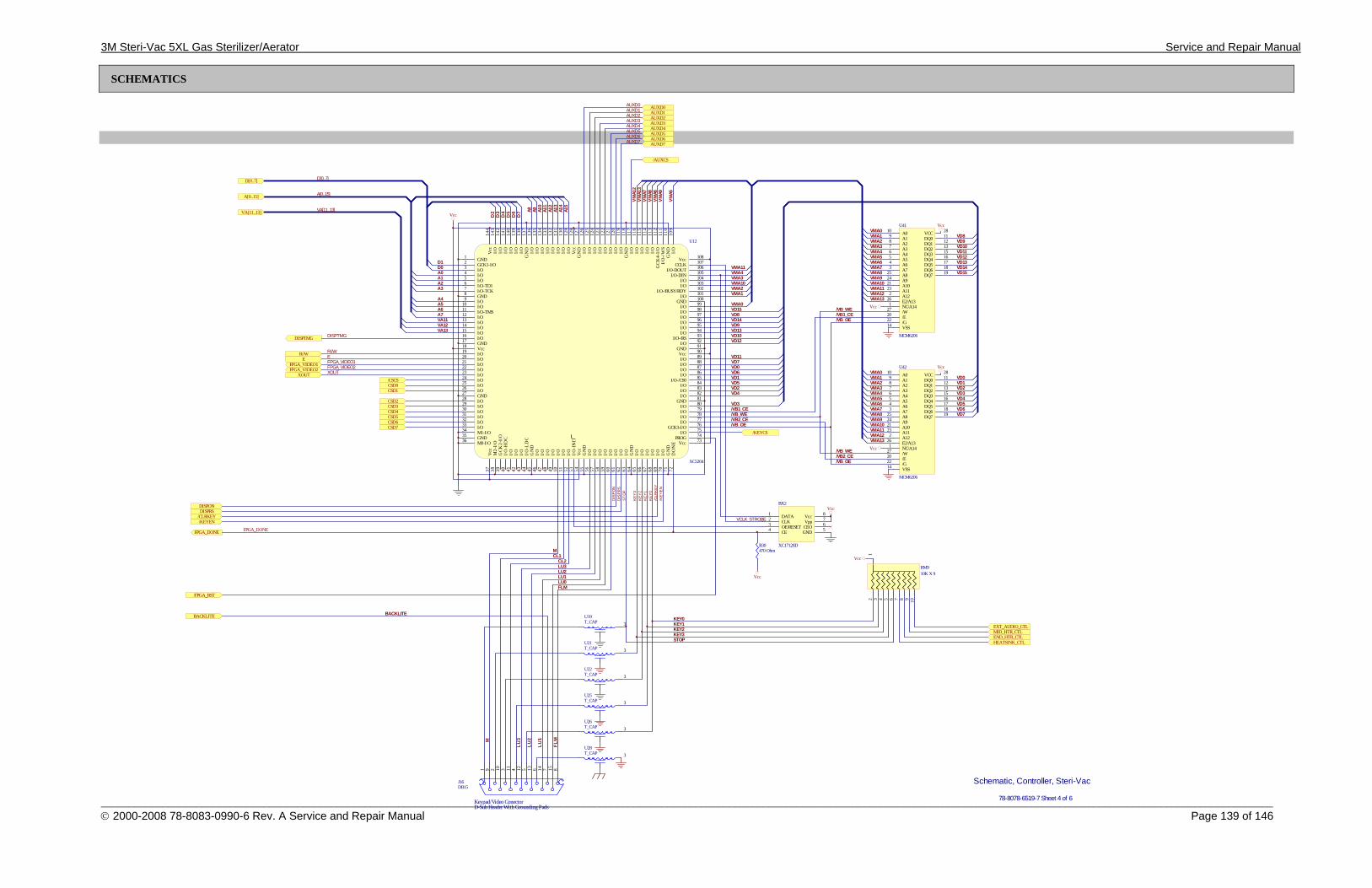
3M Steri-Vac 5XL Gas Sterilizer/Aerator Service and Repair Manual
_________________________________________________________________________________________________________________________________________________________________________________________________________________ © 2000-2008 78-8083-0990-6 Rev. A Service and Repair Manual Page 139 of 146
SCHEMATICS
DATA1
CLK2
OE/RESET3
CE4 GND 5CEO 6Vpp 7Vcc 8
BX2
XC17128D
Vcc
A010
A19
A28
A37
A46
A55
A64
A73
A825
A924
A1021
A1123
A122
E2/A1326
NC/A141
/W27
/E20
/G22
VSS14
VCC 28
DQ0 11
DQ1 12
DQ2 13
DQ3 15
DQ4 16
DQ5 17
DQ6 18
DQ7 19
U41
MCM6206
A010
A19
A28
A37
A46
A55
A64
A73
A825
A924
A1021
A1123
A122
E2/A1326
NC/A141
/W27
/E20
/G22
VSS14
VCC 28
DQ0 11
DQ1 12
DQ2 13
DQ3 15
DQ4 16
DQ5 17
DQ6 18
DQ7 19
U42
MCM6206
A9 A10
A11
A12
A13
A14
A15
A0A1A2
VA11VA12VA13
A3
A4A5A6A7
A8
D0D1
D2
D3
D4
D5
D6
D7
VMA1
2VM
A13
VMA7
VMA8
VMA6
VMA9
VMA5
VMA11VMA4VMA3VMA10VMA2VMA1
VMA0VMA1VMA2VMA3VMA4VMA5VMA6VMA7VMA8VMA9VMA10VMA11VMA12
VD0VD1VD2VD3VD4VD5VD6VD7
VD8VD9VD10VD11VD12VD13VD14VD15
VD15VD8VD14VD9VD13VD10VD12
VD11VD7VD0VD6VD1VD5VD2VD4
VD3
/FPGA_RST
XOUT
DISPTMG
R//WE
VMA0VMA13
Vcc
Vcc
KEY0KEY1KEY2KEY3STOP
BACKLITE BACKLITE
Keypad/Video ConectorD-Sub Header With Grounding Pads
1 9 2 10 3 11 4 12 5 13 6 14 7 15 8
J16DB15
MCL1
CL2LU3LU2LU1LU0FLM
FPGA_VIDEO1
M
LU3
LU2
LU1
FLM
/VB_WE
/VB1_CE
/VB_OE/VB2_CE
Vcc
Vcc
DISPRSDISPON
/CLRKEY/KEYEN
Schematic, Controller, Steri-Vac
78-8078-6519-7 Sheet 4 of 6
A[0..15]
VA[11..13]
D[0..7] D[0..7]
A[0..15]
VA[11..13]
DISPTMG
R//WEFPGA_VIDEO1
XOUT
AUXD0AUXD1AUXD2AUXD3AUXD4AUXD5AUXD6AUXD7
AUXD0AUXD1AUXD2AUXD3AUXD4AUXD5AUXD6AUXD7
/AUXCS
VMA0VMA1VMA2VMA3VMA4VMA5VMA6VMA7VMA8VMA9VMA10VMA11VMA12VMA13
/VB_WE
/VB_OE
/VB_OE/VB2_CE/VB_WE
/VB1_CE
/KE
YE
N/C
LRK
EY
DIS
PR
SD
ISP
ON
KE
Y0
KE
Y1
KE
Y2
KE
Y3
ST
OP
Vcc
12 3 4 5 6 7 8 9 10
RM910K X 9
Vcc
HEATSINK_CTLEND_HTR_CTLMID_HTR_CTLEXT_AUDIO_CTL
CSD0CSD1
CSD2CSD3CSD4CSD5CSD6CSD7
GND1
GCK1-I/O2
I/O3
I/O-TD16
I/O-TCK7
GND8
I/O-TMS11
I/O12
I/O13
I/O14
I/O16
GND17
Vcc18
I/O19
I/O20
I/O21
I/O22
I/O23
I/O24
GND27
I/O28
I/O29
I/O32
GND35
M0-I/O36
Vcc
37
M2-
I/O
38
GCK
2-I/
O39
I/O
-HD
C40
I/O
43
I/O
-LD
C44
GN
D45
I/O
48
I/O
49
I/O
51
I/O
52
I/O
-IN
IT53
Vcc
54
GN
D55
I/O
56
I/O
57
I/O
58
I/O
59
I/O
60
I/O
61
GN
D64
I/O
65
I/O
66
I/O
69
I/O
70
GN
D71
DO
NE
72
Vcc 73PROG 74I/O 75GCK3-I/O 76
I/O 80
I/O 79
GND 81
I/O 84I/O-/CS0 85
I/O 88I/O 89Vcc 90GND 91I/O 92I/O-/RS 93
I/O 96I/O 97
GND 100
I/O-/BUSY/RDY 102
I/O-DIN 105I/O-DOUT 106CCLK 107Vcc 108
I/O10
9G
ND
110
I/O
-/W
S11
1G
CK
4-I/O
112
I/O11
5I/O
116
GN
D11
8
I/O12
1
I/O12
3I/O
124
I/O12
6G
ND
127
Vcc
128
I/O12
9
I/O13
3I/O
134
I/O13
0I/O
131
GN
D13
7I/O
138
I/O13
9
I/O13
2
I/O14
2I/O
143
Vcc
144
I/O15
I/O33
M1-I/O34
I/O
50
I/O 86I/O 87
I/O 94I/O 95
I/O 101
I/O12
2
I/O12
5
I/O4
I/O5
I/O9
I/O10
I/O25
I/O26
I/O30
I/O31
I/O
41
I/O
42
I/O
46
I/O
47
I/O
62
I/O
63
I/O
67
I/O
68
I/O 77I/O 78
I/O 82I/O 83
I/O 98I/O 99
I/O 103I/O 104
I/O11
3I/O
114
I/O11
7
I/O11
9I/O
120
I/O13
5I/O
136
I/O14
0I/O
141
U12
XC5204
FPGA_VIDEO2 FPGA_VIDEO2
/KEYCS
/CSCS
VCLK_STROBE
3U19T_CAP
3U21T_CAP
3U22T_CAP
3U25T_CAP
3U26T_CAP
3U28T_CAP
FPGA_DONE
R30470 Ohm
Vcc
FPGA_DONE
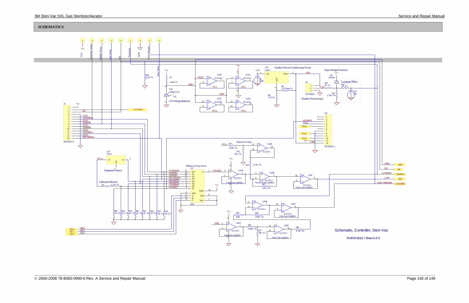
3M Steri-Vac 5XL Gas Sterilizer/Aerator Service and Repair Manual
_________________________________________________________________________________________________________________________________________________________________________________________________________________ © 2000-2008 78-8083-0990-6 Rev. A Service and Repair Manual Page 140 of 146
SCHEMATICS
3
21
411
U39A
TLC27L4
5
67
U39B
TLC27L4
10
98
U39C
TLC27L4
12
1314
U39D
TLC27L4
Vcc
R17
221K .1%
R16 11.3K .1%
R14
24.9K .1%
3
21
411
U33ATLC27L45
67
U33BTLC27L4
10
98
U33CTLC27L4 12
1314
U33DTLC27L4
Adjustment Voltage
RECTEMPIN CH07
EXA0
RH
CHPRESS
EXA2
EXA3
VREF
CHTEMPINZONE1INZONE2IN
AMTEMPINHSTEMPINCATEMPINEXTEMP1
VTC1
Multiplexed Temp Sensors
Unity Gain Amplifier Non-Inverting Amplifier
Vcc
SEL0SEL1SEL2
X013
X114
X215
X312
X41
X55
X62
X74
INH6
A11
B10
C9
X 3
VDD 16
VSS 8
VEE 7
U9
4051
Vcc
R181K .1%
R191K .1%
R201K .1%
R211K .1%
R221K .1%
R231K .1%
R241K .1%
R251K .1%
Unity Gain Amplifier
CH07
RH
CHPRESS
VREF
R2 2.21K 1%
Temperature Sensor
Calibration Resistor
T11
NC
2
T2 3
U47TD5A
1 11 1 11
Vcc
1
VCC
Cha
mbe
r Te
mp
Mid
dle
Tem
p
End
Tem
p
RH Pr
essu
re
GN
D
R1
2.49K 1%
Vcc
2.5V Voltage Reference
VREF
NC
Vin1
AD
J3
+Vout 2
U20LM317
R82.7K 1%
R9221 Ohms 1%
C10.1uF
+24V
123
J8
HEADER 3
R101K .1%
R112.75K .1%
R121K .1%
D9IN4148
Vcc
Chamber Pressure Conditioning CircuitInput Voltage Protection
C591uF
Lowpass Filter
Chamber Pressure Input
CHTEMPIN
ZONE1IN
ZONE2IN
HSTEMPINVTC4
VTC4
VTC3
VTC2
LATCHPOS
123456789101112
J10
HEADER 12
EXTEMP1VTC2
Vcc
SEL0SEL1SEL2
+15V
+15V
RH
Vcc
Schematic, Controller, Steri-Vac
78-8078-6519-7 Sheet 6 of 6
R1510K .1%
T_MUXED
P_IN
R29221K 1%
23
1
D10LM236-2.5V
123456789
1011121314
J4
HEADER 14
RECTEMPIN
3
21
411
U40A
TLC27L4
10
98
U40C
TLC27L4
5
67
U40B
TLC27L4
12
1314
U40D
TLC27L4
Vcc
VREFR36
4.64K .1%R3710K .1%
R38
5.11K .1%
R39
0.0K
R40
24.9K .1%
LEAKPRES
VTC2
Unity Gain Amplifier
Unity Gain Amplifier
Unity Gain Amplifier
VREF
VTC2
VREF
VTC1
VTC4VTC3
VTC3
1
LEAK_PRESURE
Leak
Pre
sure
1R
ec T
emp
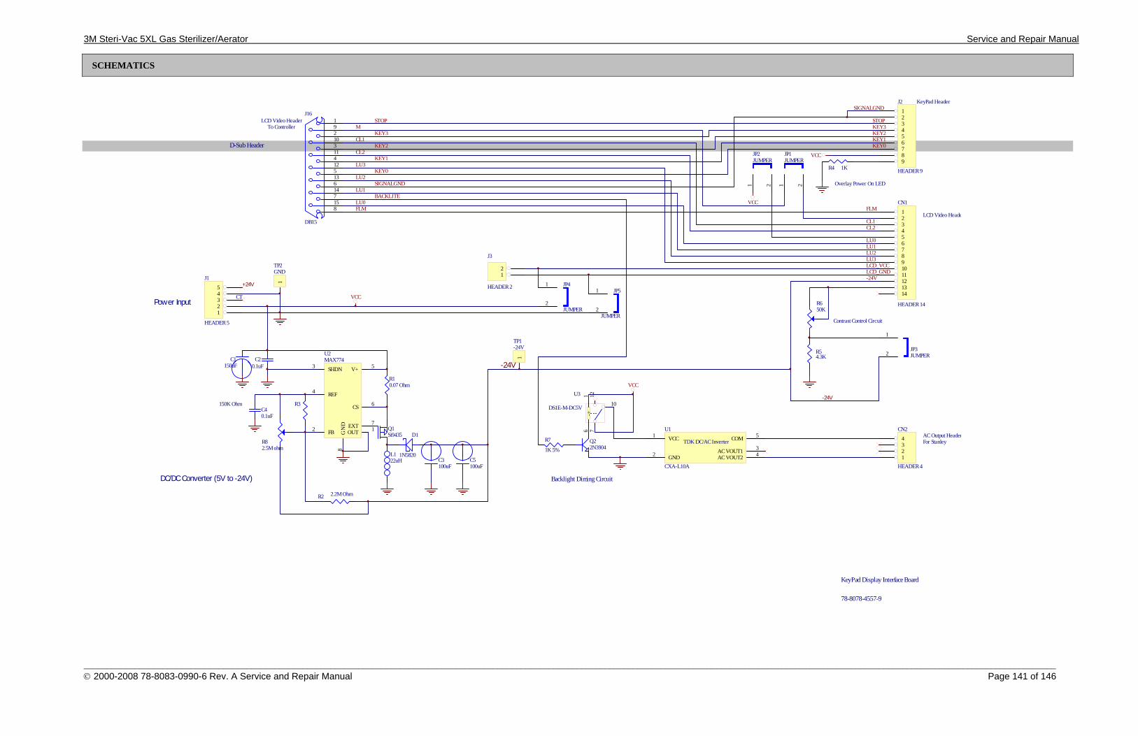
3M Steri-Vac 5XL Gas Sterilizer/Aerator Service and Repair Manual
_________________________________________________________________________________________________________________________________________________________________________________________________________________ © 2000-2008 78-8083-0990-6 Rev. A Service and Repair Manual Page 141 of 146
SCHEMATICS
1234567891011121314
CN1
HEADER 14
1234
CN2
HEADER 4
1 2
JP1JUMPER
12345
J1
HEADER 5
VCC
R4 1K
VCC
R54.3K
Contrast Control Circuit
LCD Video Heade
KeyPad Header
AC Output Header
LCD Video HeaderTo Controller
Overlay Power On LED
-24V
KEY0KEY1KEY2KEY3STOP
SIGNALGND
For Stanley
LU0LU1LU2LU3
CL2CL1
FLM
CT
1 2
JP2JUMPER
VCC1
GND2
COM 5
AC VOUT2 4
TDK DC/AC Inverter
AC VOUT1 3
U1
CXA-L10A
123456789
J2
HEADER 9
D-Sub Header
KeyPad Display Interface Board
78-8078-4557-9
1
2JP3JUMPER
192103114125136147158
J16
DB15
VCCFLMLU0
LU1
LU2
LU3
CL1
CL2
STOP
KEY3
KEY2
KEY1
KEY0
SIGNALGND
BACKLITE
M
R7
1K 5%
Backlight Diming Circuit
712
-6
+1
10
U3
DS1E-M-DC5V
VCC
12
J3
HEADER 2
LCD_VCCLCD_GND
1
2
JP4
JUMPER
1
2
JP5
JUMPER
-24V
DC/DC Converter (5V to -24V)
Power Input
+24V
R2 2.2M Ohm
R3150K OhmC40.1uF
C20.1uF
C1150uF
C3100uF
R10.07 Ohm
L122uH
OUT 1FB2
SHDN3
REF4
V+ 5
CS 6
EXT 7
GN
D8
U2MAX774
-24V
R650K
Q1Si9435
Q22N3904
D1
1N5820
R82.5M ohm
1
TP1-24V
1
TP2GND
C5100uF
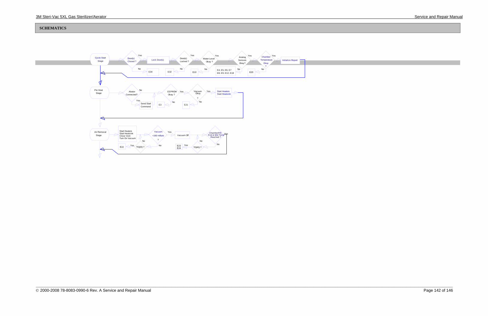
3M Steri-Vac 5XL Gas Sterilizer/Aerator Service and Repair Manual
_________________________________________________________________________________________________________________________________________________________________________________________________________________ © 2000-2008 78-8083-0990-6 Rev. A Service and Repair Manual Page 142 of 146
SCHEMATICS
No
Yes
Lock Door(s)Cycle Start
StageDoor(s)Closed ?
E34No
YesDoor(s)Locked ?
E32No
YesWater Level
Okay ?
E10No
Yes
SensorsOkay?
E4, E5, E6, E7E8, E9, E12, E18
Analog
No
YesChamberTemperature
?
E20
OkayInitialize Report
No
YesEnd & Mid TempChamber/HS
Reached ?
No
E23 Yes
Air RemovalStage
Start Heaters
Close Vent
Vacuum
?Turn On Vacuum
YesVacuum Off
No
No
TO(20) ?E22Yes
Start Heatsink<160 mBars
TO(45) ?E24
Pre HeatStage
No
Yes
AbatorConnected?
Send StartCommand
No
YesVacuumOkay
?
E21
Start Heaters
No
YesOkay ?
EEPROM
E3
Start Heatsink
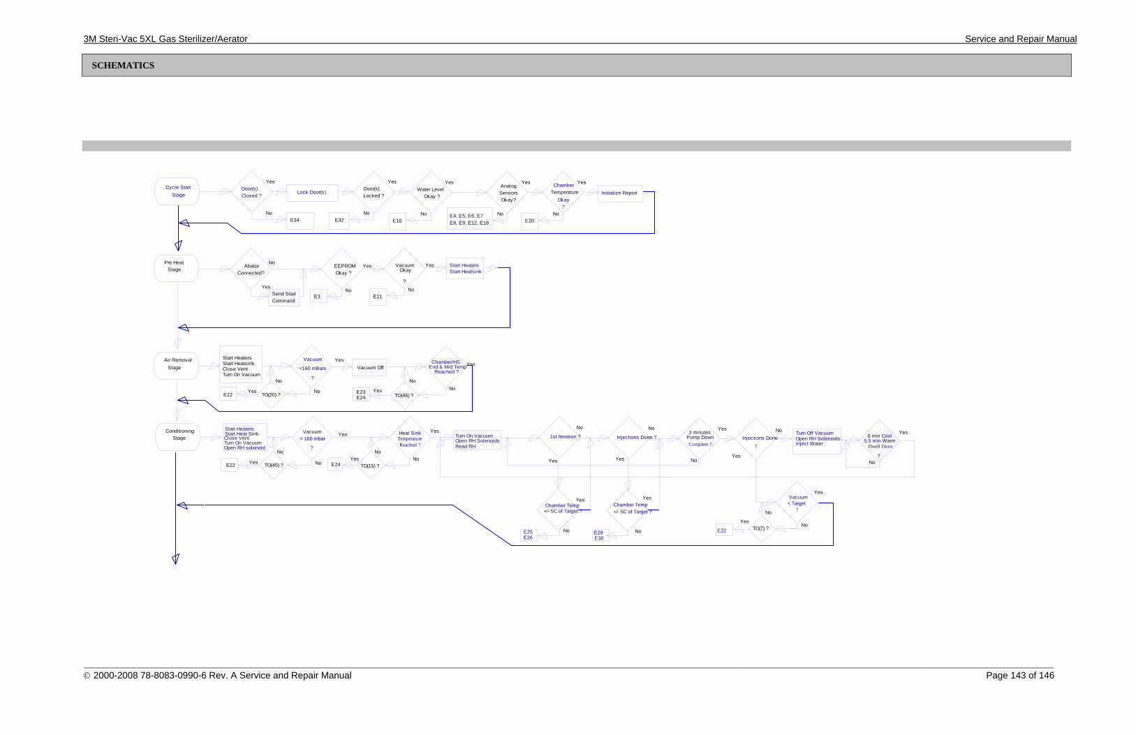
3M Steri-Vac 5XL Gas Sterilizer/Aerator Service and Repair Manual
_________________________________________________________________________________________________________________________________________________________________________________________________________________ © 2000-2008 78-8083-0990-6 Rev. A Service and Repair Manual Page 143 of 146
SCHEMATICS
Yes
Complete ?Pump Down3 minutes
No
TO(7) ?
ConditioningStage
Start Heaters
Close VentTurn On Vacuum
No
?
Yes
No
TO(45) ?E22 Yes E24No
No
TO(15) ?Yes
Read RHOpen RH Solenoids
YesStart Heat Sink Heat Sink TemperatureReached ?
Vacuum< 160 mbar
?Open RH solonoid
Turn On Vacuum
Dwell Done
8 min Cool5.5 min WarmInject Water
Open RH SolenoidsTurn Off Vacuum
Yes
?
Injections DoneNo
No
Yes
?< Target Vacuum
No
Yes
No
Yes
E22
?
1st Iteration ? Injections Done ?
Chamber Temp Chamber Temp+/- 5C of Target ? +/- 5C of Target ?
YesYes
E29E25 NoNo
NoNo
YesYes
E30E26
No
Yes
Lock Door(s)Cycle Start
StageDoor(s)Closed ?
E34No
YesDoor(s)Locked ?
E32No
YesWater Level
Okay ?
E10No
Yes
SensorsOkay?
E4, E5, E6, E7E8, E9, E12, E18
Analog
No
YesChamberTemperature
?
E20
OkayInitialize Report
No
YesEnd & Mid TempChamber/HS
Reached ?
No
E23 Yes
Air RemovalStage
Start Heaters
Close Vent
Vacuum
?Turn On Vacuum
YesVacuum Off
No
No
TO(20) ?E22Yes
Start Heatsink<160 mBars
TO(45) ?E24
Pre HeatStage
No
Yes
AbatorConnected?
Send StartCommand
No
YesVacuumOkay
?
E21
Start Heaters
No
YesOkay ?
EEPROM
E3
Start Heatsink
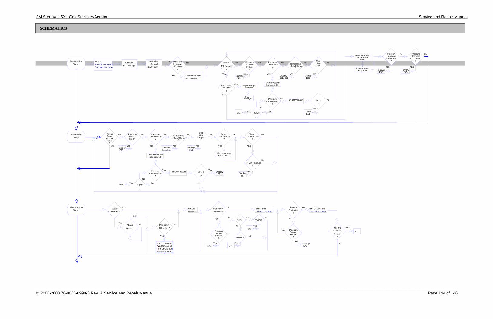
3M Steri-Vac 5XL Gas Sterilizer/Aerator Service and Repair Manual
_________________________________________________________________________________________________________________________________________________________________________________________________________________ © 2000-2008 78-8083-0990-6 Rev. A Service and Repair Manual Page 144 of 146
SCHEMATICS
Gas InjectionStage
PunctureEO Cartridge
Wait for 20Seconds
PressureIncrease
<20 mBars?
Yes
Yes Turn on PunctureSim Solenoid
180 Seconds
?
No No Pressure
?
SensorFailure
No Pressure
?
>Ambient-80No Temperature
?Out of Range
NoStop
?
KeyPressed
Yes YesYesYes
Error During
?
Gas Inject
Yes
Display Display DisplayE60E52, E53E73
Turn On Vacuum
Pressure
?<Ambient-80
No
Yes
No
TO(2) ?E71Yes
Increment GI
GI > 2
?
No
Yes
Turn Off Vacuum
DisplayE51
ErrorManager
NoGI = 0
Start Timer
Timer >
No
Read PuncturePin Position
Switch
Pressure
?
Increase
YesStop Cartridge
Puncture
Stop CartridgePuncture
< 50 mBars
DisplayE50
No Pressure
?
Increase
Yes
< 200 mBars
DisplayE75
No
Yes
Read Puncture PinSet Latching Relay
Gas ExposeStage Preset
?
No Pressure
?
SensorFailure
No Pressure
?
>Ambient-80No Temperature
?Out of Range
NoStop
?
KeyPressed
Yes YesYesYesDisplay Display Display
E60E52, E53E73
Turn On Vacuum
Pressure
?<Ambient-180
No
Yes
No
TO(2) ?E71Yes
Increment GI
GI > 2
?
No
YesTurn Off Vacuum Display
E51
NoTimer >
ExposeTime
Timer
?= 5 minutes
Yes
NoNo Timer
?> 5 minutes
Yes
No
Min pressure =P - P*.20
P < Min Pressure?
YesDisplay
E57
No
Yes
Final VacuumStage
No
Yes
AbatorConnected?
Yes
Abator Ready?
No
Yes
Pressure >250 mBars?
No
Turn On VacuumWait for 3.5 secTurn Off VacuumWait for 5.5 sec
Turn On
Yes
Pressure >160 mBars?
No
Yes
Pressure Sensor
No
Failure?
E73
YesAbator ?
No
TO(90) ?
NoTO(30) ?
E71
E71
Yes
Yes
VacuumStart Timer
YesTimer >3 Minutes
No
?
No Pressure
?
SensorFailure
YesDisplayE73
Turn Off Vacuum
No
Record Pressure1 Record Pressure 2
YesP2 - P1< Min DP (5 mbar)
?
E73
No
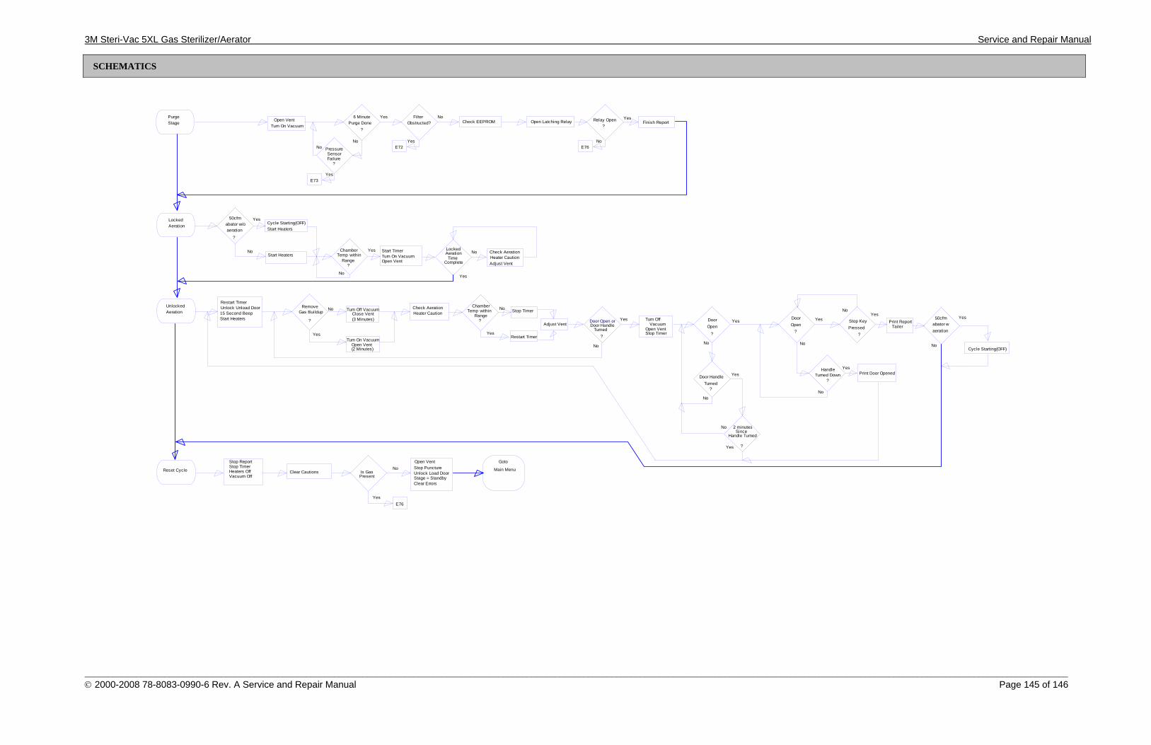
3M Steri-Vac 5XL Gas Sterilizer/Aerator Service and Repair Manual
_________________________________________________________________________________________________________________________________________________________________________________________________________________ © 2000-2008 78-8083-0990-6 Rev. A Service and Repair Manual Page 145 of 146
SCHEMATICS
UnlockedAeration
Stop Key
Restart TimerUnlock Unload Door
Start Heaters
ChamberTemp within
Range
No
Yes
Check AerationHeater Caution Stop Timer
Restart Timer
Adjust Vent Door HandleTurned
?
No
Yes
No
Turn Off
Stop TimerOpen Vent
YesDoorOpen
?
No
Door HandleTurned
?
No
YesDoorOpen
?Pressed
?
Print Door Opened
15 Second BeepRemove
Gas Buildup
YesTurn On Vacuum
(2 Minutes)
?
Turn Off Vacuum
(3 Minutes)
No
Print ReportTailer
Cycle Starting(OFF)
50cfm
aerationabator w
No
Yes?
Yes
HandleTurned Down
?
Yes
No
2 minutesSince
Handle Turned
?Yes
Yes
No
No
Vacuum
Close Vent
Open Vent
Door Open or
LockedAeration
ChamberTemp within
Range?
Start Heaters
No
Yes
Open VentTurn On Vacuum
LockedAeration
TimeComplete
Yes
No Check AerationHeater CautionAdjust Vent
Cycle Starting(OFF)50cfm
aerationabator w/o
?
No Start Timer
Start Heaters
Yes
PurgeStage
Open VentTurn On Vacuum
Yes6 Minute
No
Yes
Pressure SensorFailure
?
E73
No
Open Latching Relay Relay Open
No
?
Yes
E76
Finish ReportFilter No
Obstructed?
YesE72
Check EEPROM
?Purge Done
Reset Cycle
Stop ReportStop TimerHeaters OffVacuum Off
Open Vent
Clear Cautions Is GasPresent
YesE76
Stop PunctureUnlock Load DoorStage = StandbyClear Errors
Goto
Main MenuNo
3M Steri-Vac 5XL Gas Sterilizer/Aerator Service and Repair Manual
______________________________________________________________________________________ © 2000-2008 78-8083-0990-6 Rev. A Service and Repair Manual Page 146 of 146
3 Health Care 3M Center Building 275-4E-01 St. Paul, MN 55144-1000 1-800-228-3957
3M Canada, Inc. P.O. Box 5757 Terminal A London, Ontario, Canada, N6A4T1 1-800-563-2921
Recycled paper 40% pre-consumer 10% post-consumer Litho in U.S.A. with 3M film, proofing systems and offset plates. Steri-Vac, Steri-Gas, Attest, Comply and Indox are registered trademarks of 3M. © 3M 2000-2008 78-8083-0990-6 Rev. A
Distribution Limited To Current 3M Approved Service Providers
Health Care/3M Page 1 of 7
Equipment
58 Bulletin Subject: 5XLe Pr 5.11 Software Release
Date: August 14, 2008 Machines Affected: All 5XLe Steri-Vac, serial numbers 720001
and above and serial numbers 820001 and above and all upgraded 5XL to 5XLe Steri-Vacs. The production 5XLe Steri-Vacs, beginning with 721438 and 820209, will contain the Pr 5.11 version EPROM.
Condition: New software release to correct bugs, add
features and add languages. Cause: N/A Solution: N/A This Bulletin is published in conjunction with the release of new 5XLe Program, Version Pr 5.11 and describes the bug fixes, added features and languages. Following the release notes, the new Machine Personality Code (MPC) index is provided. (Make a copy of the new MPC index and keep it with your service manual.) The step by step instructions of how to change the MPC is provided in the service manual. Note: Hospital users must use a ‘CLASSIC’ MPC and the validated cycles of 37°C and 55°C, with 3 hours and 1 hour of gas exposure
Distribution Limited To Current 3M Approved Service Providers
Health Care/3M Page 2 of 7
time, respectively. There must be no deviation from these gas exposure times. Humidity, pressure, and temperature may be adjusted to meet location conditions. Note: Whenever a change is made to any sterilizer setting, power must be cycled at the sterilizer to ensure the change is recorded in the Controller memory. Note: There is a new Service Manual that is being released with this version of software. The part number of the new 5XLe Service Manual for use with Pr 5.11 software is 78-8083-0990-6, revision A. For sterilizers that use software revision Pr 5.10 continue to use the existing service manual for the 5XLe, part number 78-8078-8601-1, revision B.

Distribution Limited To Current 3M Approved Service Providers
Health Care/3M Page 3 of 7
5XLe Pr 5.11 Software Release Notes
This software update: • Adds additional languages (Polish, Turkish, Romanian, Russian, and Hebrew) • Fixes the door handle position switch bug and adds E19 error code • Provides for optional 2-hr abated aeration* • Provides for optional extension of the gas expose stage times* ** • Improves how the Mandatory Locked Aeration DIP switch alters aeration time • Allows setting of the Define Cycles menu locked aeration time in all MPCs** • Fixes the bug of a missing stripchart on next cycle after Emergency Aeration • Does NOT print C12 (“unload” door was opened) on the stripchart • Moves the 30 minutes of locked aeration to the Purge stage (to mimic the old 5XL) • Removes nitrogen injection code & display of leak test timer/result to make room for other changes • Updates the default & copyright dates, default MPC, software version, and PROM checksums • Adds a Low Humidity Caution (C16) (with a 35% RH threshold for assertion) • Allows Classic personality 37°C or 55°C cycle to be disabled** * MPC must be selected to include this feature. ** DIP SW2-1 must be set to “UP” position to use this feature. Adds additional languages The words “START”, “PRECONDITION”, “GAS EXPOSE”, and “AERATE” on the operator screen have been translated into Polish, Turkish, Romanian, Russian, and Hebrew. The Site Setup menu is enhanced to allow the selection of Polish, Turkish, Romanian, Russian, and Hebrew in addition to the existing language options. Due to limited program memory, four program PROMs are being released.
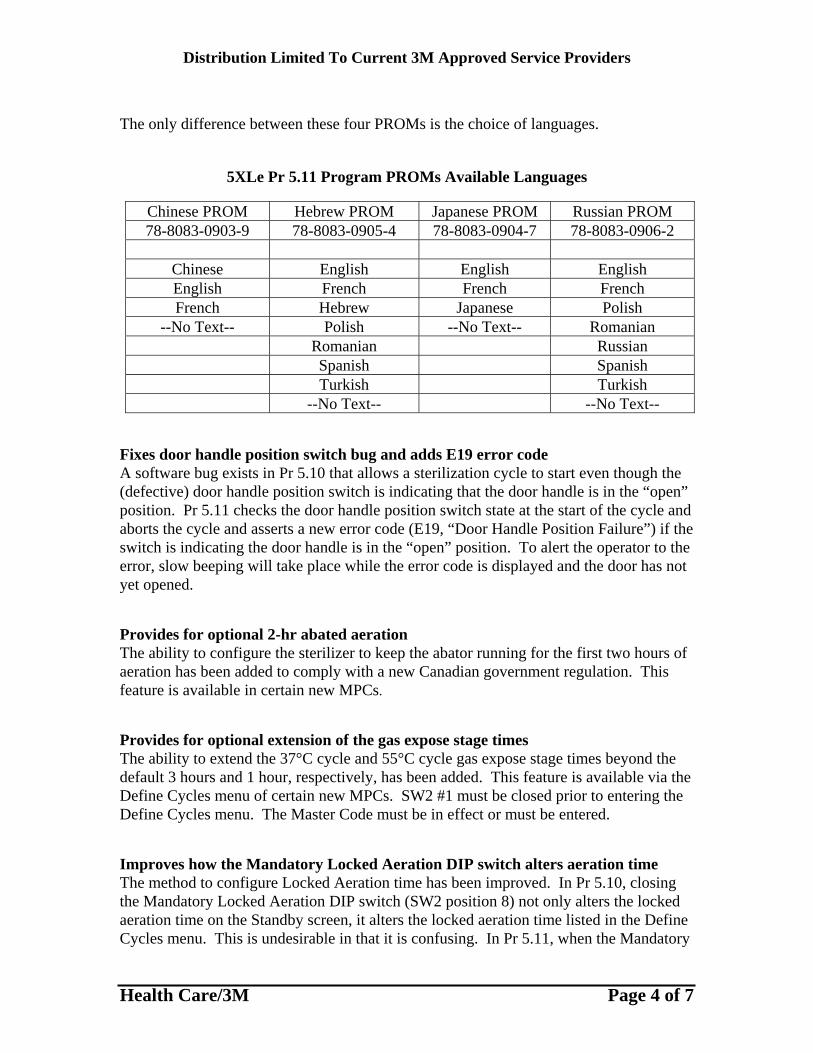
Distribution Limited To Current 3M Approved Service Providers
Health Care/3M Page 4 of 7
The only difference between these four PROMs is the choice of languages.
5XLe Pr 5.11 Program PROMs Available Languages
Chinese PROM Hebrew PROM Japanese PROM Russian PROM 78-8083-0903-9 78-8083-0905-4 78-8083-0904-7 78-8083-0906-2
Chinese English English English English French French French French Hebrew Japanese Polish
--No Text-- Polish --No Text-- Romanian Romanian Russian Spanish Spanish Turkish Turkish --No Text-- --No Text--
Fixes door handle position switch bug and adds E19 error code A software bug exists in Pr 5.10 that allows a sterilization cycle to start even though the (defective) door handle position switch is indicating that the door handle is in the “open” position. Pr 5.11 checks the door handle position switch state at the start of the cycle and aborts the cycle and asserts a new error code (E19, “Door Handle Position Failure”) if the switch is indicating the door handle is in the “open” position. To alert the operator to the error, slow beeping will take place while the error code is displayed and the door has not yet opened. Provides for optional 2-hr abated aeration The ability to configure the sterilizer to keep the abator running for the first two hours of aeration has been added to comply with a new Canadian government regulation. This feature is available in certain new MPCs. Provides for optional extension of the gas expose stage times The ability to extend the 37°C cycle and 55°C cycle gas expose stage times beyond the default 3 hours and 1 hour, respectively, has been added. This feature is available via the Define Cycles menu of certain new MPCs. SW2 #1 must be closed prior to entering the Define Cycles menu. The Master Code must be in effect or must be entered. Improves how the Mandatory Locked Aeration DIP switch alters aeration time The method to configure Locked Aeration time has been improved. In Pr 5.10, closing the Mandatory Locked Aeration DIP switch (SW2 position 8) not only alters the locked aeration time on the Standby screen, it alters the locked aeration time listed in the Define Cycles menu. This is undesirable in that it is confusing. In Pr 5.11, when the Mandatory
Distribution Limited To Current 3M Approved Service Providers
Health Care/3M Page 5 of 7
Locked Aeration DIP switch is closed (Up) the locked aeration time on the Standby screen is extended to three hours if it is less than three hours in the Define Cycles menu. When the Mandatory Locked Aeration DIP switch is open (Down), the locked aeration time on the Standby screen is the locked aeration time in the Define Cycles menu. Allows setting of the Define Cycles menu locked aeration time in all MPCs Customers have requested that the Locked Aeration time be adjustable. (The 8XL Steri-Vac already has this capability.) Pr 5.11 allows, in all MPCs, the Locked Aeration time in the Define Cycles menu to be adjustable. This feature is available via the Define Cycles menu. SW2 #1 must be closed prior to entering the Define Cycles menu. The Master Code must be in effect or must be entered. Fixes the bug of a missing stripchart on next cycle after Emergency Aeration Pr 5.10 has a bug where the first cycle following an Emergency Aeration is lacking the stripchart header and graph. Only the trailer prints at the end of the cycle. Pr 5.11 fixes this bug. Does NOT print C12 (“unload” door was opened) on the stripchart Pr 5.10 prints a C12 on the stripchart. C12 means the unload door (on a two-door 5XL) was opened. (When the door is open C12 is also displayed on the screen to alert an operator on the load side of the 5XL to this fact.) Some customers do not want the C12 being printed because their work procedures require any non-error-free data log (e.g., a stripchart from a sterilizer) to have an explanation about, or investigation into, the (apparent) anomaly. A C12 is benign. It need not be printed on the stripchart. Pr 5.11 does NOT print C12 on the stripchart. Moves the 30 minutes of locked aeration to the Purge stage (to mimic the old 5XL) Pr 5.10, for Classic personalities, has 6 minutes of Purge and 24 minutes of Locked Aeration. (These 30 minutes appear as the 30 minutes of Locked Aeration on the Standby screen.) This does not mimic the old 5XL. The old 5XL had 30 minutes of Purge and 0 minutes of Locked Aeration. Pr 5.11 makes the Purge stage 30 minutes in duration and sets the (default) Locked Aeration time to 0 minutes. Removes nitrogen injection code & display of leak test timer/result to make room for other changes Code for injection of nitrogen has been removed to make room in the PROM for the other changes in Pr 5.11. Nitrogen injection was a feature planned but never completely implemented. Furthermore, no nitrogen-injecting 5XL Steri-Vac (i.e., “5XLe” Steri-Vac) has ever been ordered, and, as the necessary companion hardware changes have never been implemented, it would not be possible to build a machine to fulfill the order. Because of the additional screen space needed to display the new, larger, fonts in the Precondition box, the Enhanced mode leak test timer (and leak result) is not displayed in
Distribution Limited To Current 3M Approved Service Providers
Health Care/3M Page 6 of 7
Pr 5.11. The leak test time and the leak result are still printed on the stripchart Digital Report. Updates the default & copyright dates, default MPC, software version, and PROM checksums The default date, software copyright date, default MPC, software version number, and PROM checksums are updated for Pr 5.11. The default MPC is changed to US5, an “RH Monitor” MPC, because non-RH 5XLe’s are no longer offered for sale. Adds a Low Humidity Caution (C16) (with a 35% RH threshold for assertion) A Low Humidity caution, C16, has been added in Classic personalities in Pr 5.11. Just before cartridge puncture the humidity is compared to the threshold of 35% RH. If the humidity is below this threshold then C16 is printed in the stripchart graph and on the stripchart trailer. Additionally, C16 is displayed on the screen for the remainder of the cycle. Allows Classic personality 37°C or 55°C cycle to be disabled Customers have requested that one or the other cycle (i.e., 37°C cycle or 55°C cycle) be disabled (so that it cannot be selected via the cycle temperature button on the Standby screen). In Pr 5.11, for Classic personalities, the 37°C cycle or the 55°C cycle (but not both at the same time) can be disabled. This feature is available via the Define Cycles menu. SW2 #1 must be closed prior to entering the Define Cycles menu. Note: The 37°C or 55°C cycle can be re-enabled in a similar manner with the following exception. When a cycle is re-enabled, the master code is requested. To just enable the cycle, and not adjust any other parameter, press the STOP button 4 times. The machine will enable the cycle and the display will return to the previous menu screen.
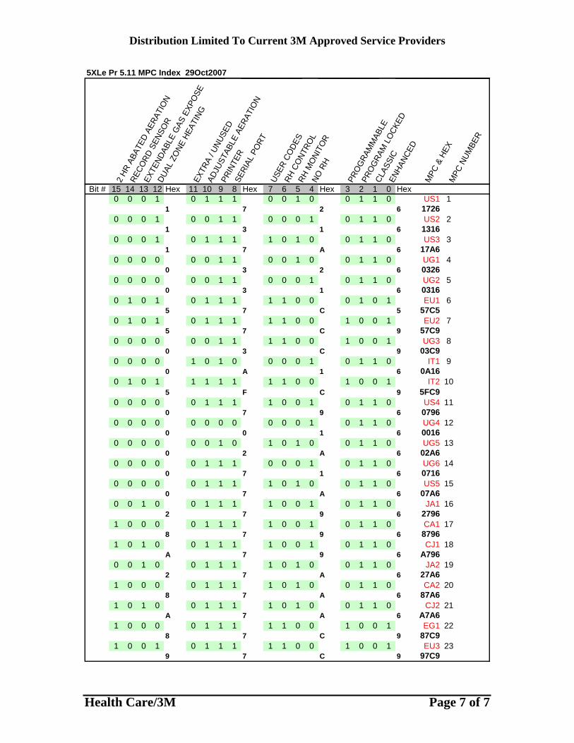
Distribution Limited To Current 3M Approved Service Providers
Health Care/3M Page 7 of 7
5XLe Pr 5.11 MPC Index 29Oct2007
2 HR
ABA
TED
AERA
TIO
N
RECO
RD S
ENSO
R
EXTE
NDAB
LE G
AS E
XPO
SE
DUAL
ZO
NE H
EATI
NGEX
TRA
/ UNU
SED
ADJU
STAB
LE A
ERAT
ION
PRIN
TER
SERI
AL P
ORT
USER
CO
DES
RH C
ONT
ROL
RH M
ONI
TOR
NO R
H
PRO
GRA
MM
ABLE
PRO
GRA
M L
OCK
ED
CLAS
SIC
ENHA
NCED
MPC
& H
EXM
PC N
UMBE
R
Bit # 15 14 13 12 Hex 11 10 9 8 Hex 7 6 5 4 Hex 3 2 1 0 Hex0 0 0 1 0 1 1 1 0 0 1 0 0 1 1 0 US1 1
1 7 2 6 17260 0 0 1 0 0 1 1 0 0 0 1 0 1 1 0 US2 2
1 3 1 6 13160 0 0 1 0 1 1 1 1 0 1 0 0 1 1 0 US3 3
1 7 A 6 17A60 0 0 0 0 0 1 1 0 0 1 0 0 1 1 0 UG1 4
0 3 2 6 03260 0 0 0 0 0 1 1 0 0 0 1 0 1 1 0 UG2 5
0 3 1 6 03160 1 0 1 0 1 1 1 1 1 0 0 0 1 0 1 EU1 6
5 7 C 5 57C50 1 0 1 0 1 1 1 1 1 0 0 1 0 0 1 EU2 7
5 7 C 9 57C90 0 0 0 0 0 1 1 1 1 0 0 1 0 0 1 UG3 8
0 3 C 9 03C90 0 0 0 1 0 1 0 0 0 0 1 0 1 1 0 IT1 9
0 A 1 6 0A160 1 0 1 1 1 1 1 1 1 0 0 1 0 0 1 IT2 10
5 F C 9 5FC90 0 0 0 0 1 1 1 1 0 0 1 0 1 1 0 US4 11
0 7 9 6 07960 0 0 0 0 0 0 0 0 0 0 1 0 1 1 0 UG4 12
0 0 1 6 00160 0 0 0 0 0 1 0 1 0 1 0 0 1 1 0 UG5 13
0 2 A 6 02A60 0 0 0 0 1 1 1 0 0 0 1 0 1 1 0 UG6 14
0 7 1 6 07160 0 0 0 0 1 1 1 1 0 1 0 0 1 1 0 US5 15
0 7 A 6 07A60 0 1 0 0 1 1 1 1 0 0 1 0 1 1 0 JA1 16
2 7 9 6 27961 0 0 0 0 1 1 1 1 0 0 1 0 1 1 0 CA1 17
8 7 9 6 87961 0 1 0 0 1 1 1 1 0 0 1 0 1 1 0 CJ1 18
A 7 9 6 A7960 0 1 0 0 1 1 1 1 0 1 0 0 1 1 0 JA2 19
2 7 A 6 27A61 0 0 0 0 1 1 1 1 0 1 0 0 1 1 0 CA2 20
8 7 A 6 87A61 0 1 0 0 1 1 1 1 0 1 0 0 1 1 0 CJ2 21
A 7 A 6 A7A61 0 0 0 0 1 1 1 1 1 0 0 1 0 0 1 EG1 22
8 7 C 9 87C91 0 0 1 0 1 1 1 1 1 0 0 1 0 0 1 EU3 23
9 7 C 9 97C9
Distribution Limited To Current 3M Approved Service Providers
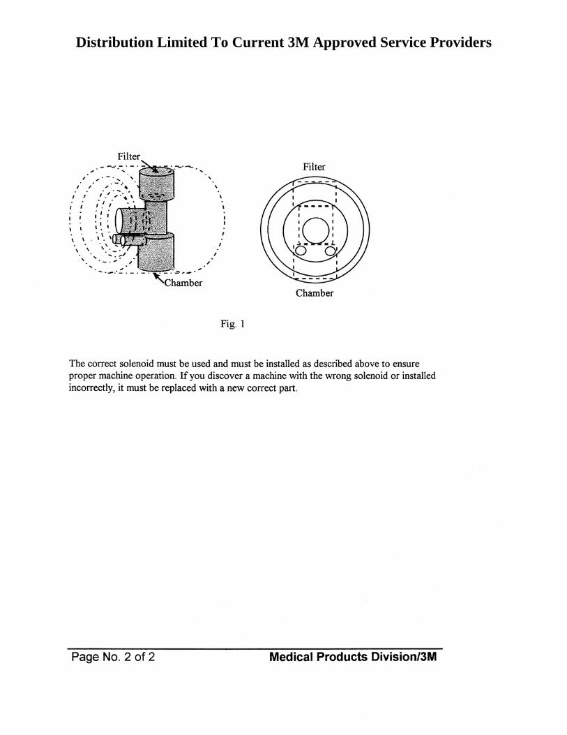
Distribution Limited To Current 3M Approved Service Providers
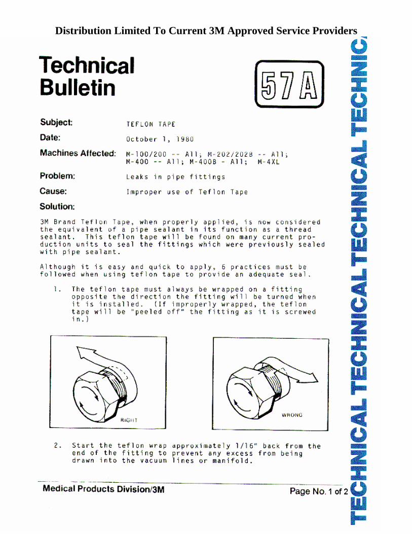
Distribution Limited To Current 3M Approved Service Providers
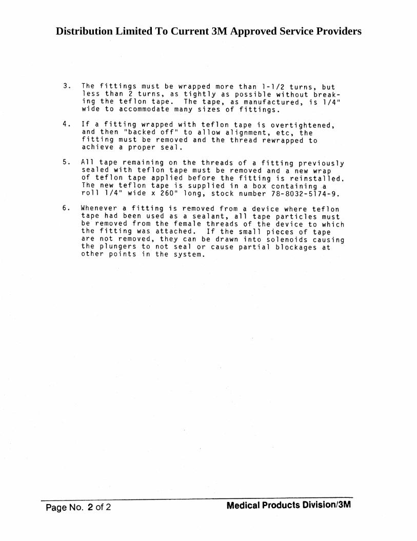
Distribution Limited To Current 3M Approved Service Providers
Distribution Limited To Current 3M Approved Service Providers
Distribution Limited To Current 3M Approved Service Providers
Distribution Limited To Current 3M Approved Service Providers
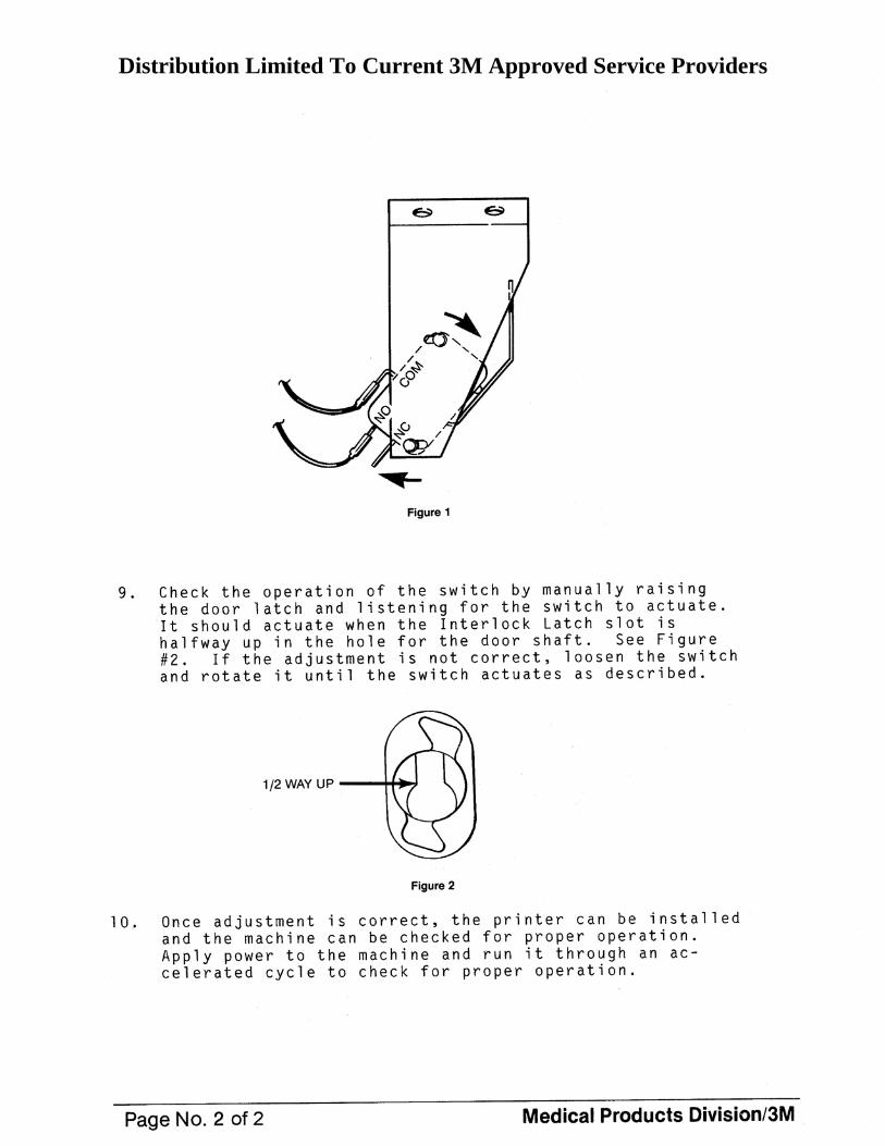
Distribution Limited To Current 3M Approved Service Providers
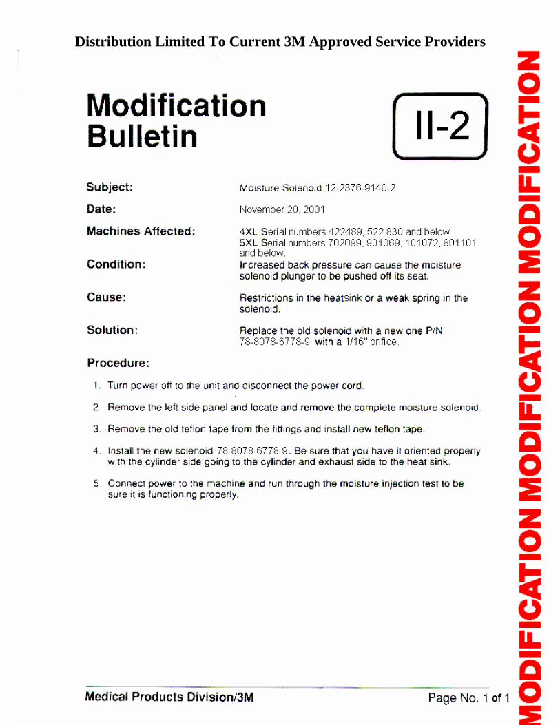
Distribution Limited To Current 3M Approved Service Providers
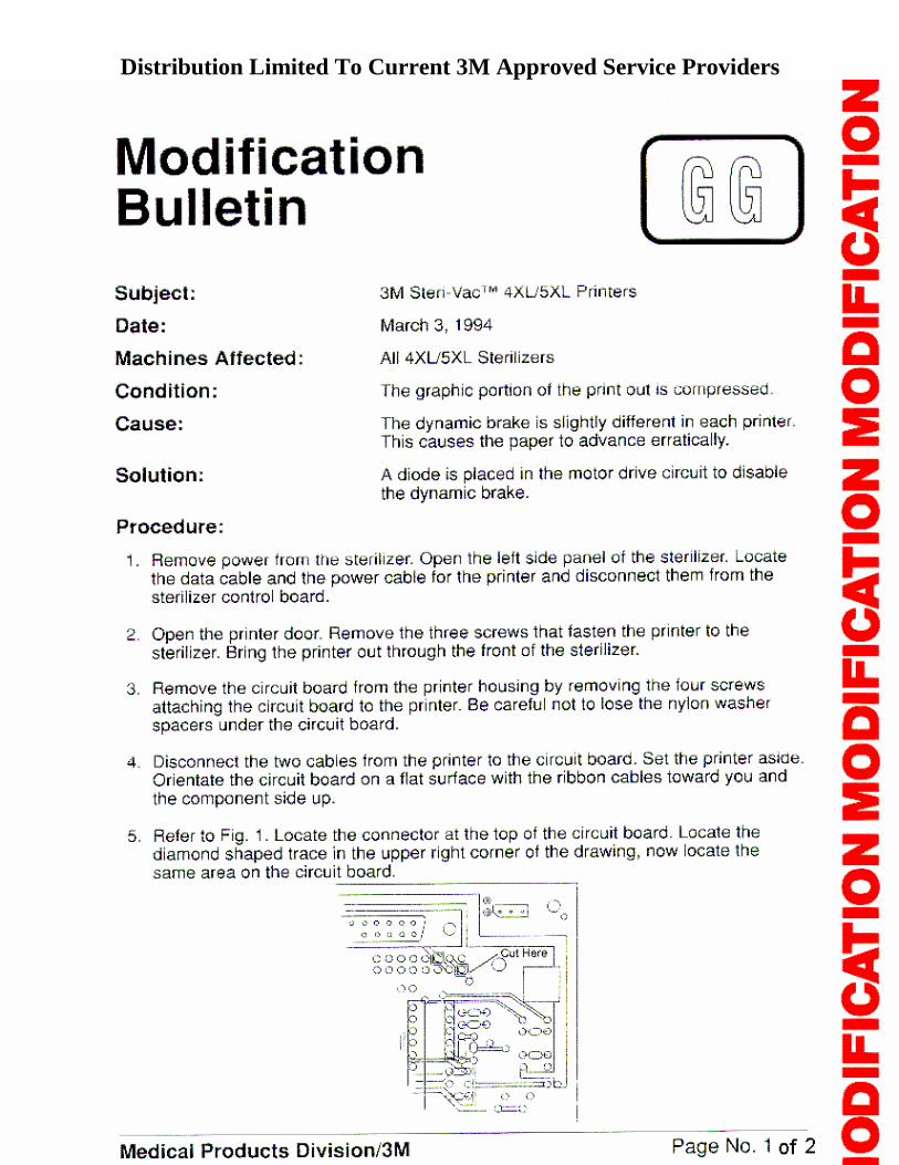
Distribution Limited To Current 3M Approved Service Providers
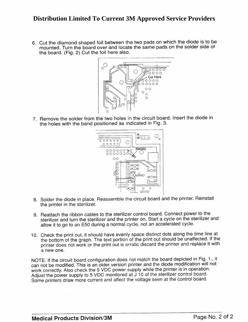
Distribution Limited To Current 3M Approved Service Providers
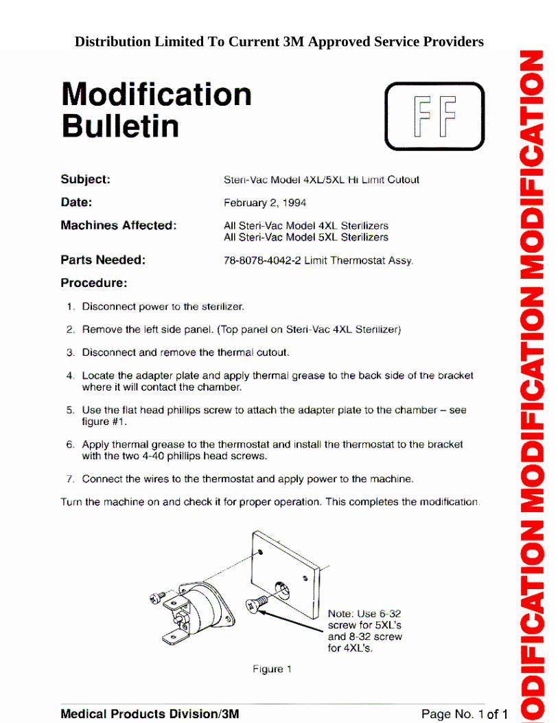
Distribution Limited To Current 3M Approved Service Providers
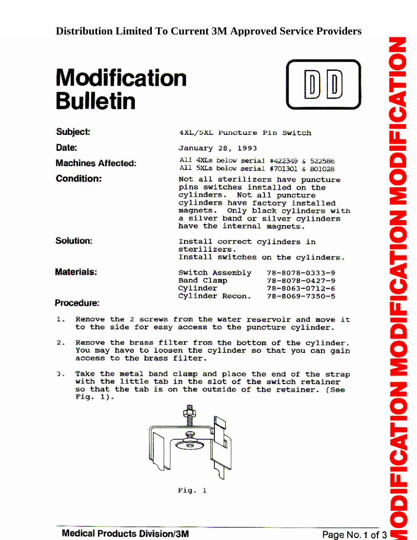
Distribution Limited To Current 3M Approved Service Providers
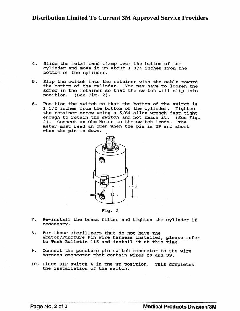
Distribution Limited To Current 3M Approved Service Providers
Distribution Limited To Current 3M Approved Service Providers

Distribution Limited To Current 3M Approved Service Providers
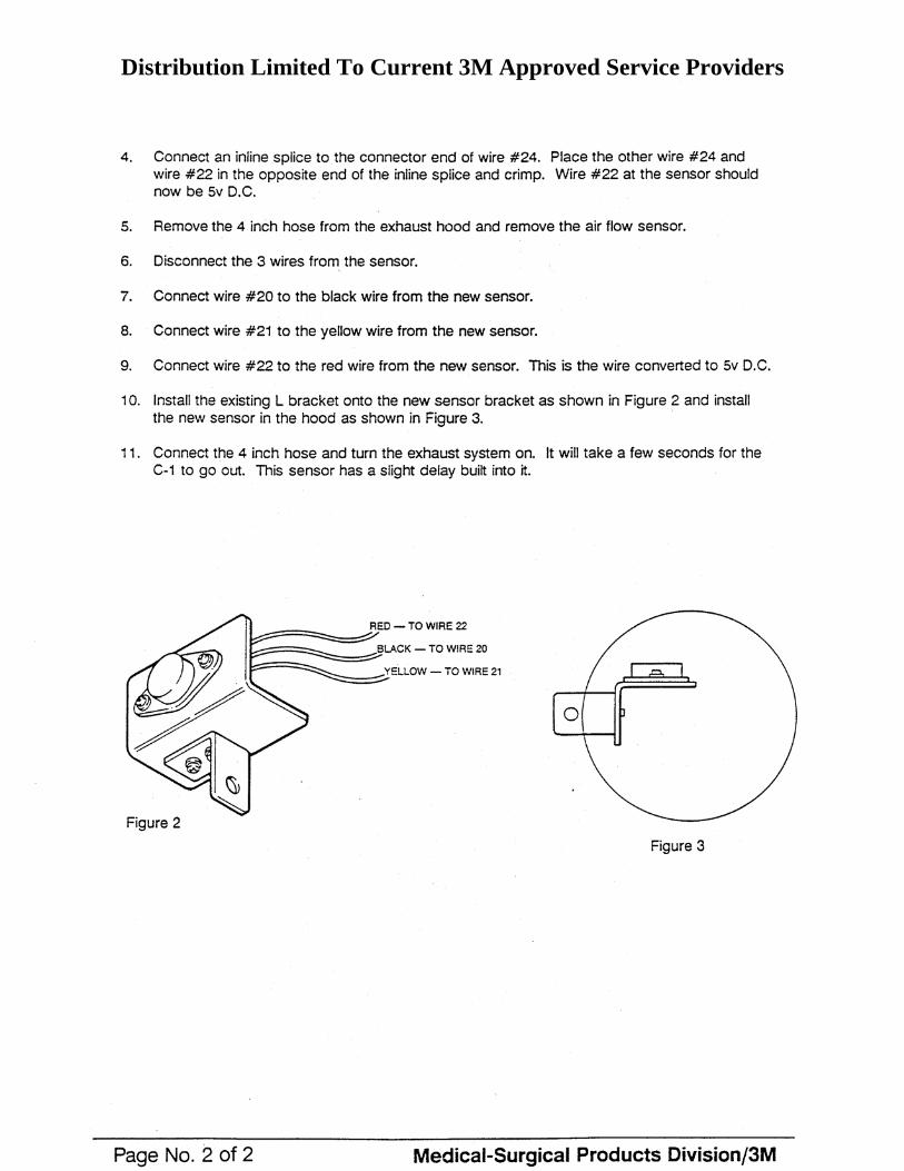
Distribution Limited To Current 3M Approved Service Providers
Distribution Limited To Current 3M Approved Service Providers
Distribution Limited To Current 3M Approved Service Providers
Health Care/3M Page 1 of 2
Equipment
54 Bulletin Subject: 4XL/old 5XL/old XL Controller Board Update Date: July 6, 2007 Machines Affected: All 4XL sterilizers, 5XL sterilizers with serial numbers less
than 720000 and XL aerators with serial numbers less than 150000.
Condition: Controller Boards, part number 78-8078-9224-1, can no
longer be made. Cause: Some of the components for producing the Controller
Boards are no longer available. Solution: Part number 78-8078-9224-1 will be made obsolete.
Reconditioned boards will continue to be used under part number 78-8055-5900-8.
The controller board, part number 78-8078-9224-1 for the above sterilizers, can no longer be manufactured. Critical components can not be obtained. Therefore, part number 78-8078-9224-1 will be deleted from the parts list. A reconditioned board process has been is use for some time, and will continue to be used as the supply for Controller Boards for the above sterilizers. The Controller Board part number that will be used for all orders is part number 78-8055-5900-8. The Controller Board under part number 78-8055-5900-8 will be shipped without a microprocessor chip and without an EPROM. Therefore, when a Controller Board is replaced, make sure the microprocessor and EPROM chips are removed from the old board and placed in the new board. If through further testing, it is determined that the microprocessor is at fault, please contact Technical Support on 800-292-6298, opt 5 (or US 652-575-5884) for further analysis.
Distribution Limited To Current 3M Approved Service Providers
Health Care/3M Page 2 of 2
For US Field Reps—if you have a Controller Board under part number 78-8078-9224-1, continue to use that board. When existing stock is used up, the replacement board will be 78-8055-5900-8. For all other Field Service Reps or Subsidiaries—any new orders for 4XL, old 5XL, and old XL Controller Boards should be placed using part number 78-8055-5900-8. CRITICAL NOTE: It is very important that when a Controller Board is replaced on the above sterilizers and aerator, the failed board is sent back to the US Health Care Service Center, no matter the condition. These boards will be returned to the manufacturing plant for possible reconditioning.
Distribution Limited To Current 3M Approved Service Providers
Health Care/3M Page 1 of 4
Equipment
48 Bulletin Subject: Service - Final Checks Process Date: August 5, 2002 Machines Affected: 4XL, 5XL, and 8XL Condition: N/A Cause: N/A Solution: This Bulletin is written to describe the Final Checks and
procedures that must always be performed on the sterilizer before the sterilizer is put back into use.
Check #1: Temperature Calibration Use either the 49C method or the 2231 Ohm resistor method.
Temperature Calibration Procedure Using the 49C Method (Preferred method on all sterilizers)
1. Put the Fluke thermocouple under the TCO on a 5XL or near the chamber temperature sensor on a 4XL. Use silver tape to attach thermocouple, if needed. Use Thermal Grease on the Thermocouple / Chamber interface to insure good heat transfer. DO NOT place thermocouple under the Chamber High Limit Thermostat on a 4XL.
2. Put the unit in cycle and allow the display to go to 51 C.
3. Then turn power off, set DIP SW1-1 and SW1-3 to the up position, and allow the
temperature (on the fluke) to go to exactly 49 C. At that point, turn the unit on and it will calibrate to within a couple of tenths of a degree of true accuracy. (The door latch will activate indicating acceptance of the new calibration.)
Distribution Limited To Current 3M Approved Service Providers
Health Care/3M Page 2 of 4
4. Turn power off and set DIP Switch SW1-1 and SW1-3, down.
5. Turn power on. Unit will come up in a C3, and the unit will continue in cycle.
6. Observe the display and Fluke to insure the temperatures match. If OK, remove the thermocouple and press stop button to terminate cycle. If temperature on Fluke and on the display do not match, repeat steps 1 – 6.
IMPORTANT NOTE: If machine will not accept the calibration (vacuum pump comes on instead of latch activation), the machine is too far out of calibration to accept the 49 C. To correct, observe the display when the Fluke reaches 49 C. If above 51 C, calibrate the temperature in 2 C increments until between 51 C and 49 C. Then make final calibration to 49 C. If the temperature of the chamber reaches 51 C, and the Fluke is below 49 C, the 2231 Ohm resistor method must be used to calibrate the temperature.
Temperature Calibration Procedure Using the 2231 Ohm Resistor (Recommended when had to change the controller board on 4XL and on old 5XL, just to get close to correct temperature. Then use above method to get accurate calibration.)
1. Take the 2231 ohm variable resistor from your tool case and insert the ends into the multi-meter (common and Ohms), set to read resistance. Adjust resistor until the multi-meter reads 2231.
2. Measure the temperature of the chamber by placing the thermocouple near the
location of the chamber temperature sensor. Attach Thermocouple with Silver Tape if needed. Add Thermal Grease to thermocouple / chamber interface to insure good heat transfer. Start a warm cycle, and allow the temperature to stabilize at 55C.
3. Note the difference between the actual chamber temperature measured by the
thermocouple and the displayed temperature. This is the amount you want to offset. (For example, suppose the actual temperature is measured as 53C, 2 degrees lower than displayed. If more than 2C offset, see NOTE below.)
4. Disconnect the chamber sensor at the connector and put the 2231 ohm resistor
leads into the connector end that goes to the controller board, not the connector end that goes to the sensor. The display will now read 48C.
5. Adjust the resistor until the display reads the offset temperature correction. (For
this example the actual is 2 degrees lower (See #3), so the resistor should be adjusted until the display reads 50C).
Distribution Limited To Current 3M Approved Service Providers
Health Care/3M Page 3 of 4
6. Turn the power off. Place DIP switches 1 and 3 Up and turn the power on again.
This now calibrates the temperature.
7. Turn the power off again, remove the variable resistor and reconnect the chamber temperature sensor.
8. Place DIP switches 1 and 3 down again and turn the power on. The calibration
procedure is complete. Recheck the chamber temperature to see that the actual temperature is the same as displayed.
9. If the temperature is now close, within 1-2 degrees C, use the 49C method
described in the first section to precisely calibrate the temperature. IMPORTANT NOTE: If the actual temperature is more than 2C offset from the displayed temperature, the calibration can not be accomplished in one calibration. The above calibration procedure will have to be done more than once, adjusting the temperature 2C at one time. THE CALIBRATION WILL NOT BE ACCOMPLISHED IF MORE THAN 2C OFFSET IS ATTEMPTED.
Check #2: Proper Default Temperature on Display Panel 1. Cycle Power 1 time
a. Check return to default cycle. b. If not at customer requested default, i.e. warm cycle or cold cycle, change
default. When power is cycled on a 4XL or old 5XL, the unit will default to the
temperature it was set on during the last in cycle power interruption. This can be a problem if the service rep interrupts power on a cold cycle and the customer runs only warm cycles. To correct this, simply cycle power after servicing to make sure the unit defaults to warm (or cold if the customer wants to default to the cold cycle). If it doesn’t, you can select the desired default cycle, start the cycle and turn the power switch off and back on. Press Stop to get an E40, open the door and press Stop again. Check for proper default by cycling power again.
Distribution Limited To Current 3M Approved Service Providers
Health Care/3M Page 4 of 4
Check #3: After Regulator Re-build or Replacement Adjust air pressure up 5 psi to account for drop across new diaphragm. Use caution with questionable air quality.
Check #4: Run Last Cycle (5XLe and 8XL only) Run last cycle information and check printout for any abnormalities. Check #5: Run Accelerated Cycle Run Accelerated cycle. Make sure cartridge is punctured properly. Check #6: Final Power Test After side panel is back on, cycle power and start a cycle. Allow machine to run for 30 seconds, check printout and make sure machine is going into cycle. If OK, press Stop, and clear code. Check #7: Personnel Discussion Discuss any abnormal information with appropriate hospital (facility) employee (Biomed, Maintenance Manager, etc.)
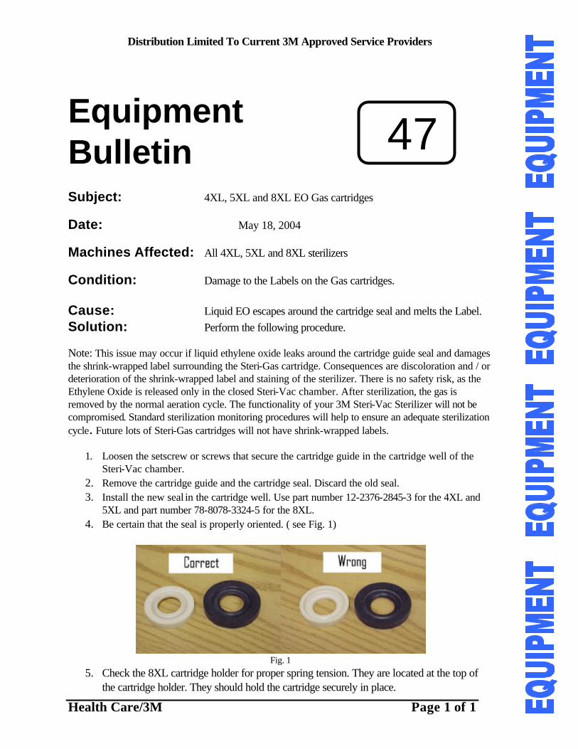
Distribution Limited To Current 3M Approved Service Providers
Health Care/3M Page 1 of 1
Equipment
Bulletin Subject: 4XL, 5XL and 8XL EO Gas cartridges
Date: May 18, 2004
Machines Affected: All 4XL, 5XL and 8XL sterilizers
Condition: Damage to the Labels on the Gas cartridges. Cause: Liquid EO escapes around the cartridge seal and melts the Label. Solution: Perform the following procedure. Note: This issue may occur if liquid ethylene oxide leaks around the cartridge guide seal and damages the shrink-wrapped label surrounding the Steri-Gas cartridge. Consequences are discoloration and / or deterioration of the shrink-wrapped label and staining of the sterilizer. There is no safety risk, as the Ethylene Oxide is released only in the closed Steri-Vac chamber. After sterilization, the gas is removed by the normal aeration cycle. The functionality of your 3M Steri-Vac Sterilizer will not be compromised. Standard sterilization monitoring procedures will help to ensure an adequate sterilization cycle . Future lots of Steri-Gas cartridges will not have shrink-wrapped labels.
1. Loosen the setscrew or screws that secure the cartridge guide in the cartridge well of the Steri-Vac chamber.
2. Remove the cartridge guide and the cartridge seal. Discard the old seal. 3. Install the new seal in the cartridge well. Use part number 12-2376-2845-3 for the 4XL and
5XL and part number 78-8078-3324-5 for the 8XL. 4. Be certain that the seal is properly oriented. ( see Fig. 1)
Fig. 1
5. Check the 8XL cartridge holder for proper spring tension. They are located at the top of the cartridge holder. They should hold the cartridge securely in place.
47
Distribution Limited To Current 3M Approved Service Providers
Health Care/3M Page 1 of 5
Equipment
Bulletin Subject: 4XL,5XL and 8XL Chamber Leaks Date: December 3, 2004 Machines Affected: All 4XL, 5XL and 8XL sterilizers Condition: Chamber vacuum leaks. Cause: The chamber does maintain the proper vacuumduring testing Solution: Perform the following procedure.
STERI-VAC STERILIZER CHAMBER VACUUM LEAK ISOLATION
The Steri-Vac sterilizer chambers are required to maintain a vacuum level through out the exposure portion of the cycle. The permissible level of vacuum loss during exposure depends on the model of sterilizer. The 4XL and 5XL sterilizers are allowed to have a 40 millibar leak in 10 minutes. The 8XL sterilizer is allowed to have a 15 millibar leak in 10 minutes. The primary source of chamber leaks is the chamber check valve. Clean or replace this component first. Then perform a leak test. To conduct the leak tests refer to the leak test procedures described in the respective Service Manuals. A kit of plugs, part number 78-8069-7680-5, is available to assist in isolating the vacuum leak. Compressed air is used to perform several functions during the operation of the sterilizer. Failures of the sealing surfaces in the compressed air components can allow compressed air to leak into the chamber and appear to be a vacuum leak in the new 5XL and 8XL The 4XL and old 5XL will not experience leaks from compressed air components although they may leak ambient air into the chamber. Isolate the source of a leak in the chamber by eliminating the compressed air components as a possible source. The following procedure will eliminate the compressed air components.
1. Perform the leak test as described in the Service Manual. Perform the “Dead End Vacuum Test”. If you cannot obtain a dead end vacuum of less than 100 millibars, the leak source could be located in the fittings on the chamber side of the chamber check valve or at the fittings around the pressure sensor and puncture solenoid valve. Note the leak rate of the dead end vacuum tester. If there is a rapid loss of vacuum when the test is stopped, the leak may be located in one of these areas.
2. Continue with the chamber leak test. If a leak is detected, re-run the test but during the 10 minute
dwell time, disconnect or turn off the compressed air and bleed the air from the compressed air line for the new 5XL or 8XL.
46A
Distribution Limited To Current 3M Approved Service Providers
Health Care/3M Page 2 of 5
3. If the leak continues at the same rate the leak is not caused by the compressed air components.
4. If the leak has stopped or been significantly reduced, one or more of the compressed air components is faulty.
5. The puncture solenoid valve, which is used to switch between compressed air and chamber
vacuum for the operation of the puncture cylinder, can leak compressed air into the chamber on the new 5XL and the 8XL. The solenoid valve plunger, seat or dirt could cause the leak.
6. Remove the puncture solenoid valve and the 1/8 inch NPT nipple from the “T” fitting and plug the
hole with 1/8 inch pipe plug, part number 26-1014-7121-2. Check the “T” fitting for cracks. (see Fig. 1) If cracks are visible, replace the “T” fitting.
Fig. 1
7. Perform the leak test again. If the leak rate is reduced replace the solenoid valve assembly. If the
leak is not reduced continue the procedure.
8. The puncture cylinder can leak compressed air into the chamber on the new 5XL or 8XL. A plug, part number 78-8083-0419-6, is available to eliminate the puncture cylinder. Install the plug and o-ring.
9. Perform the leak test again. If the leak is reduced or eliminated replace the puncture cylinder. If
the leak is not reduced continue the procedure.
10. The 4XL and old 5XL sterilizers will not experience a compressed air leak from these components. However, there could be an ambient air leak through these components. Following steps 6, 7, 8 and 9 can isolate leaks in these components. If the leak is not reduce or eliminated the leak is in another area of the sterilizer.
11. On the new and old 5XL and 8XL disconnect the tubing that connects the cartridge well to
heatsink and use a ¼ inch tube compression plug, part number 78-8005-7373-1 to seal the cartridge well port.
12. Remove the tubing from the heatsink to the chamber, one port for the 5XL and 2 ports for the
8XL. Plug the chamber port(s) with the ¼ inch tube compression plugs, part number 78-8005-7373-1.
13. Run the leak test again. If the leak is reduced or eliminated a leak exists in the heatsink assembly. .
If the leak is not reduce or eliminated the leak is in another area of the sterilizer.
14. If the leak is in the heatsink assembly, examine the components for cracks or bad seals around the compression fitting ferrules. The ferrules should not turn on the tubing. Also check the vent solenoid valve and the moisture solenoid valves and tubing.
15. On the 4XL sterilizer replace the 6 o-rings on the heatsink coupling, check the vent solenoid valve
and the tubing to the moisture solenoid valve for bad seals around the ferrules.
Note: There are several ports through the chamber wall. Some of these ports have brass bushings that can crack if the components connected to them are over tightened.
CRACK
Distribution Limited To Current 3M Approved Service Providers
Health Care/3M Page 3 of 5
16. If the leak continues, examine the bushings that go through the chamber walls. Look for hairline
cracks in the brass. (see Fig. 2) If there is a doubt replace the bushing with an appropriately sized plug, which is usually a 3/8 inch NPT plug, part number 26-1011-7274-5.
Fig.2
17. The new 5XL and 8XL have humidity sensing components that could also cause a chamber
vacuum leak. Isolate these components using a 3/8 NPT plug, 26-1011-7274-5, at the chamber connection and a ¼ inch NPT plug, 12-7992-5759-2, at the check valve connection.
18. Perform another leak test. If the leak is reduced or eliminated, the leak is in the humidity sensing
components. Examine the flex tubing for any cracks. Replace the tubing if there is a doubt. Be certain that the Exhaust ports (EXH) for the 5XL and the Atmosphere port (ATM) for the 8XL solenoid valves are connected to the chamber side of the fittings not the sensor side of the fittings.
19. Reinstall the humidity sensing components and perform another leak test. If the leak continues,
the door gaskets are the last repairable source. The old and new 5XL and the 8XL have gaskets on the back panel of the chamber as well as the load door side.
20. Examine the load door gasket for any cuts or tears. Over time, continuing vacuums in the chamber
flattens the gaskets. Once the lips of the gasket are flattened to the level of the rim around the chamber, the gasket may not seal consistently.
21. If the gasket is flattened, replace the door gasket using proper procedures described in Technical
Bulletin 74 and Equipment Bulletin 45.
22. The back plate gasket can be tested without removing the back plate. Remove the outside cabinet panel from the sterilizer.
23. Use a thin (0.010-0.020 inch) plastic or steel ruler or feeler gauge to test for good contact of the
gasket to the back plate. 24. Draw a deep vacuum in the chamber. Observe the gasket contact to the back chamber plate. Look
at the corners to be certain that the outer lip of the gasket is making contact with the back plate.
25. Slide the ruler or feeler gauge along the edge of the gasket that is against the back plate. Use only slight pressure against the gasket. When an area of poor contact is found the ruler or feeler gauge will slip between the gasket and back plate and there will be a whistling or screeching noise as air leaks past the gasket. The corners are most often the problem spots. (see Fig. 3)
CRACK
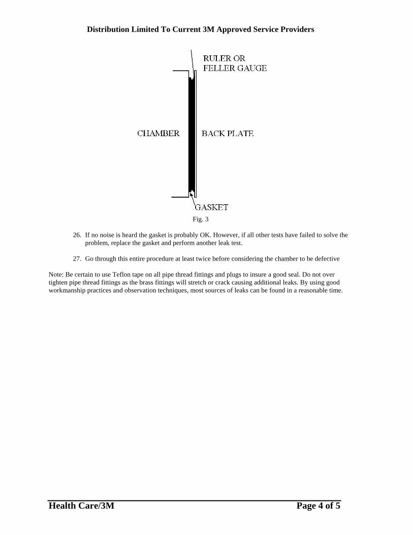
Distribution Limited To Current 3M Approved Service Providers
Health Care/3M Page 4 of 5
Fig. 3
26. If no noise is heard the gasket is probably OK. However, if all other tests have failed to solve the
problem, replace the gasket and perform another leak test. 27. Go through this entire procedure at least twice before considering the chamber to be defective
Note: Be certain to use Teflon tape on all pipe thread fittings and plugs to insure a good seal. Do not over tighten pipe thread fittings as the brass fittings will stretch or crack causing additional leaks. By using good workmanship practices and observation techniques, most sources of leaks can be found in a reasonable time.
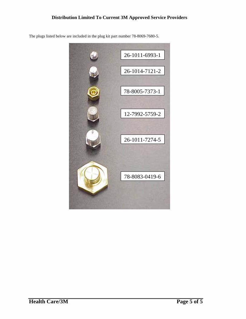
Distribution Limited To Current 3M Approved Service Providers
Health Care/3M Page 5 of 5
The plugs listed below are included in the plug kit part number 78-8069-7680-5.
26-1011-6993-1
26-1014-7121-2
78-8005-7373-1
12-7992-5759-2
26-1011-7274-5
78-8083-0419-6
Distribution Limited To Current 3M Approved Service Providers
Health Care/3M Page 1 of 2
Equipment
44 Bulletin Subject: Erratic temperature spikes, resulting in E25 and E53 Date: January 2, 2003 Machines Affected: All 4XL and 5XL sterilizers Condition: E25 or E53 error messages appear and temperature profile on
printout shows spikes or random placed data points. Cause: True temperature is out of range; or Bad connection between
Temperature sensor and Low Voltage harness; or connector on controller board is not making complete contact. On the 4XL the Heat Sink temperature is transferred to temperature sensor; or Bad Controller Board.
Solution: Note: Each one of the following solutions has been successfully used. Depending on the age of the sterilizer and previous repairs done, use the following solutions as appropriate. True Temperature is out of range: Perform a simple calibration. To accurately and quickly
calibrate either a 4 or old 5XL, put the Fluke thermocouple under the TCO on a 5XL or on a chamber sensor screw on a 4XL. Put the unit in cycle and allow
it to go to 51 C. Then induce an E-40, open the door wide, and allow the temperature (on the fluke) to go to exactly 49 C. At that point, with DIP switches 1 & 3 up, turn the unit on and it will calibrate to within a couple
of tenths of a degree of true accuracy.
Bad Connection: 1) Reconnect with new wire splices.
Distribution Limited To Current 3M Approved Service Providers
Health Care/3M Page 2 of 2
2) Cut connector pins at Temperature sensor wire and low voltage harness wire interface and solder together.
3) Cut both sets of wires and crimp on new fast on terminals.
Board Edge Connector (new 5XL): 1) Ensure that card edge connector is pushed all the
way onto the board and is not at an angle.
2) Clean gold contacts with a product similar to Archer’s TV Tuner Cleaner.
3) Use ScotchBrite to slightly clean and abrade the gold contacts on the board.
Heat Sink transfer to Temperature Sensor: 1) Skew the temperature calibration so
chamber temperature is lower than actual. (not more than 2 degrees)
2) Relocate sensor using kit 78-8078-6540-3
Controller Board is Bad: Replace controller board.

Distribution Limited To Current 3M Approved Service Providers
Health Care/3M Page 1 of 3
Equipment
42 Bulletin Subject: 4XL and 5XL Printer Replacement Date: July 10, 2002 Machines Affected: All 4XL sterilizers
5XL sterilizers below serial number 720000 and 820000 as directed by ECO 02-0076
Condition: The Seiko printers used on the 8XL and new 5XL
sterilizers is replacing the Fujitsu printers. Cause: The old Fujitsu printers are obsolete. Solution: There is a printer kit, part number 78-8078-9457-7, used to
replace the Fujitsu printers. In addition to the printer kit, the printer door must be replaced for the initial printer change over. The Printer door kit is part number 78-8078-9939-4.
1. Turn off the main power switch and remove the left side panel of the sterilizer. 2. Remove the printer data cable, printer power cable and printer switch cable from
the sterilizer controller board. It may be necessary to cut some cable ties so that the cables are free to be removed from the sterilizer.
3. Remove the printer assembly from the sterilizer by removing the 3 mounting
screws.
4. Check the lower left hand corner of the printer opening. If the corner is rounded, it must be cut to a square 900 corner. You can use a file or a metal saw. Very little metal will be removed.
5. To mount the new printer, you must first remove the front plate weldment from
the rest of the printer bracket weldment by removing 2 screws.
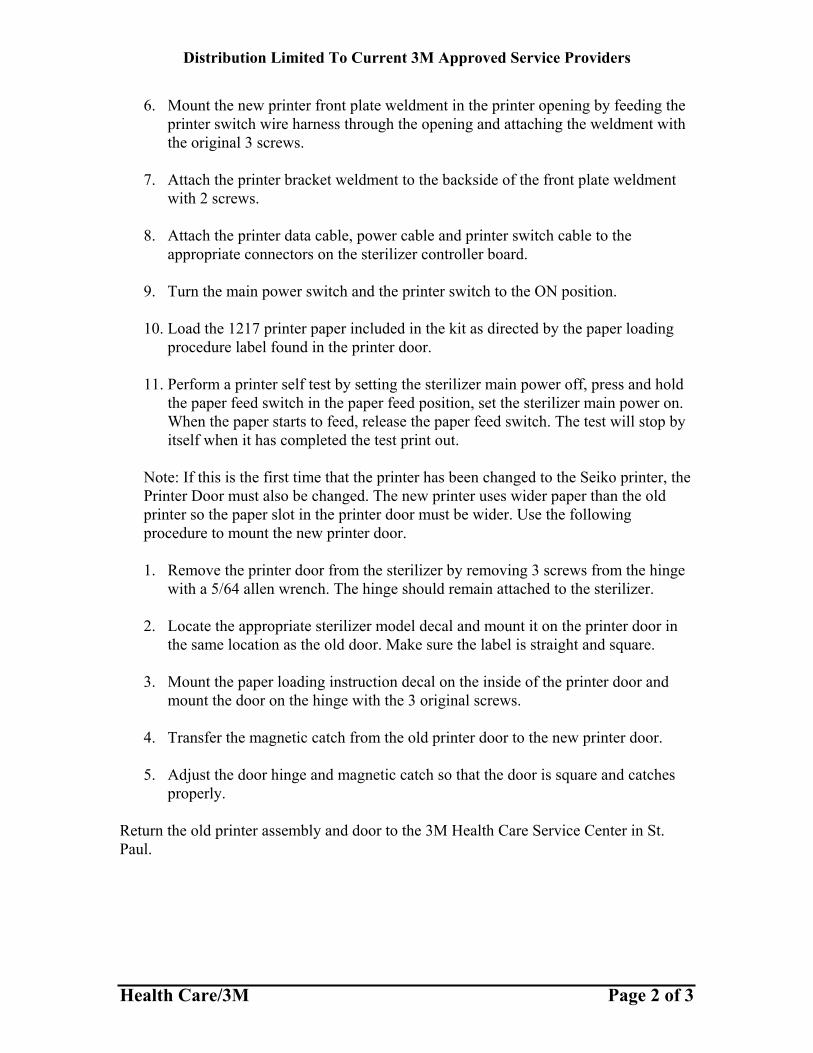
Distribution Limited To Current 3M Approved Service Providers
Health Care/3M Page 2 of 3
6. Mount the new printer front plate weldment in the printer opening by feeding the printer switch wire harness through the opening and attaching the weldment with the original 3 screws.
7. Attach the printer bracket weldment to the backside of the front plate weldment
with 2 screws.
8. Attach the printer data cable, power cable and printer switch cable to the appropriate connectors on the sterilizer controller board.
9. Turn the main power switch and the printer switch to the ON position.
10. Load the 1217 printer paper included in the kit as directed by the paper loading
procedure label found in the printer door.
11. Perform a printer self test by setting the sterilizer main power off, press and hold the paper feed switch in the paper feed position, set the sterilizer main power on. When the paper starts to feed, release the paper feed switch. The test will stop by itself when it has completed the test print out.
Note: If this is the first time that the printer has been changed to the Seiko printer, the Printer Door must also be changed. The new printer uses wider paper than the old printer so the paper slot in the printer door must be wider. Use the following procedure to mount the new printer door. 1. Remove the printer door from the sterilizer by removing 3 screws from the hinge
with a 5/64 allen wrench. The hinge should remain attached to the sterilizer. 2. Locate the appropriate sterilizer model decal and mount it on the printer door in
the same location as the old door. Make sure the label is straight and square.
3. Mount the paper loading instruction decal on the inside of the printer door and mount the door on the hinge with the 3 original screws.
4. Transfer the magnetic catch from the old printer door to the new printer door.
5. Adjust the door hinge and magnetic catch so that the door is square and catches
properly. Return the old printer assembly and door to the 3M Health Care Service Center in St. Paul.
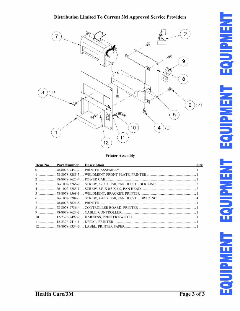
Distribution Limited To Current 3M Approved Service Providers
Health Care/3M Page 3 of 3
Printer Assembly
Item No. Part Number Description Qty 0 .....................78-8078-9457-7..... PRINTER ASSEMBLY ..................................................................................... 1 1 .....................78-8078-8285-3..... WELDMENT-FRONT PLATE, PRINTER ....................................................... 1 2 .....................78-8078-9623-4..... POWER CABLE ................................................................................................ 1 3 .....................26-1002-5266-2..... SCREW, 6-32 X .250, PAN HD, STL,BLK ZINC............................................. 2 4 .....................26-1002-6285-1..... SCREW, M3 X 0.5 X 6.0, PAN HEAD ............................................................. 2 5 .....................78-8078-9568-1..... WELDMENT, BRACKET, PRINTER .............................................................. 1 6 .....................26-1002-5204-3..... SCREW, 4-40 X .250, PAN HD, STL, BRT ZINC............................................ 4 7 .....................78-8078-5821-8..... PRINTER ........................................................................................................... 1 8 .....................78-8078-9736-4..... CONTROLLER BOARD, PRINTER ................................................................ 1 9 .....................78-8078-9624-2..... CABLE, CONTROLLER................................................................................... 1 10 ...................12-2376-9492-7..... HARNESS, PRINTER SWITCH ....................................................................... 1 11 ...................12-2376-9414-1..... DECAL, PRINTER ............................................................................................ 1 12 ...................78-8078-9354-6..... LABEL, PRINTER PAPER ............................................................................... 1
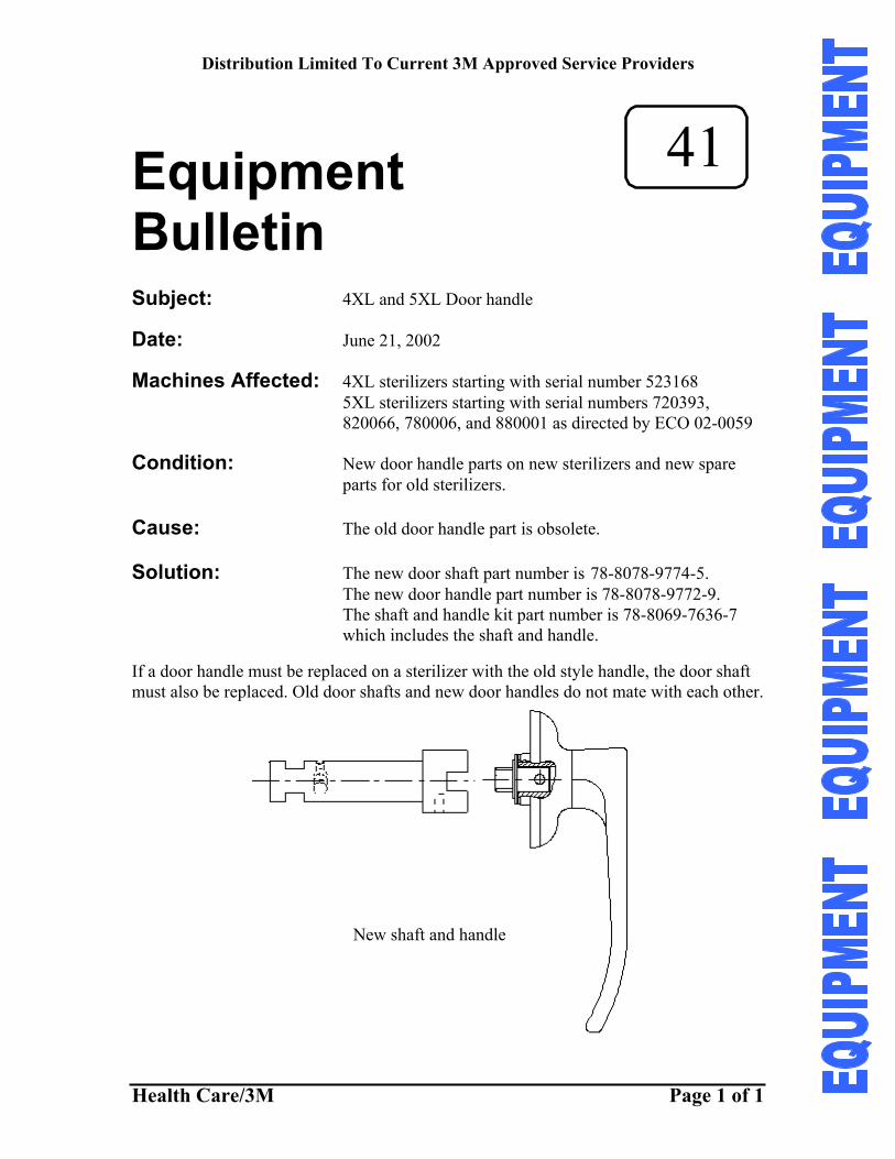
Distribution Limited To Current 3M Approved Service Providers
Health Care/3M Page 1 of 1
Equipment
41 Bulletin Subject: 4XL and 5XL Door handle Date: June 21, 2002 Machines Affected: 4XL sterilizers starting with serial number 523168
5XL sterilizers starting with serial numbers 720393, 820066, 780006, and 880001 as directed by ECO 02-0059
Condition: New door handle parts on new sterilizers and new spare
parts for old sterilizers. Cause: The old door handle part is obsolete. Solution: The new door shaft part number is 78-8078-9774-5. The new door handle part number is 78-8078-9772-9. The shaft and handle kit part number is 78-8069-7636-7
which includes the shaft and handle. If a door handle must be replaced on a sterilizer with the old style handle, the door shaft must also be replaced. Old door shafts and new door handles do not mate with each other.
New shaft and handle
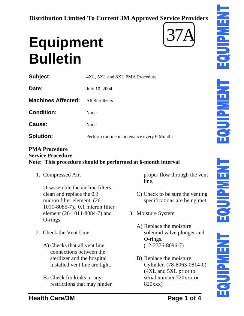
Distribution Limited To Current 3M Approved Service Providers
Health Care/3M Page 1 of 4
Equipment
37A Bulletin Subject: 4XL, 5XL and 8XL PMA Procedure Date: July 10, 2004 Machines Affected: All Sterilizers. Condition: None Cause: None Solution: Perform routine maintenance every 6 Months. PMA Procedure Service Procedure Note: This procedure should be performed at 6-month interval
1. Compressed Air.
Disassemble the air line filters, clean and replace the 0.3 micron filter element (26-1011-8085-7), 0.1 micron filter element (26-1011-8084-7) and O-rings.
2. Check the Vent Line
A) Checks that all vent line connections between the sterilizer and the hospital installed vent line are tight.
B) Check for kinks or any
restrictions that may hinder
proper flow through the vent line.
C) Check to be sure the venting
specifications are being met. 3. Moisture System
A) Replace the moisture solenoid valve plunger and O-rings. (12-2376-8096-7)
B) Replace the moisture
Cylinder. (78-8063-0814-0) (4XL and 5XL prior to serial number 720xxx or 820xxx)
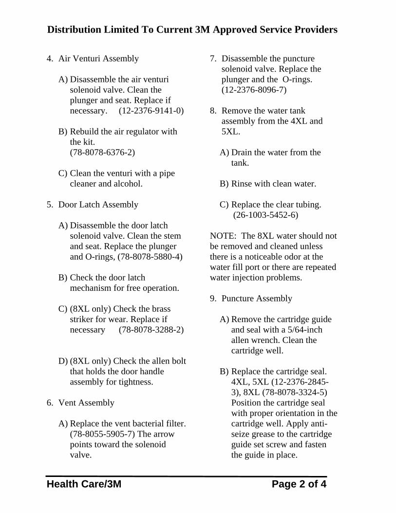
Distribution Limited To Current 3M Approved Service Providers
Health Care/3M Page 2 of 4
4. Air Venturi Assembly
A) Disassemble the air venturi solenoid valve. Clean the plunger and seat. Replace if necessary. (12-2376-9141-0)
B) Rebuild the air regulator with
the kit. (78-8078-6376-2)
C) Clean the venturi with a pipe
cleaner and alcohol. 5. Door Latch Assembly
A) Disassemble the door latch solenoid valve. Clean the stem and seat. Replace the plunger
and O-rings, (78-8078-5880-4)
B) Check the door latch mechanism for free operation.
C) (8XL only) Check the brass
striker for wear. Replace if necessary (78-8078-3288-2)
D) (8XL only) Check the allen bolt
that holds the door handle assembly for tightness.
6. Vent Assembly
A) Replace the vent bacterial filter. (78-8055-5905-7) The arrow points toward the solenoid valve.
7. Disassemble the puncture
solenoid valve. Replace the plunger and the O-rings. (12-2376-8096-7)
8. Remove the water tank
assembly from the 4XL and 5XL.
A) Drain the water from the
tank.
B) Rinse with clean water.
C) Replace the clear tubing. (26-1003-5452-6) NOTE: The 8XL water should not be removed and cleaned unless there is a noticeable odor at the water fill port or there are repeated water injection problems.
9. Puncture Assembly
A) Remove the cartridge guide and seal with a 5/64-inch allen wrench. Clean the cartridge well.
B) Replace the cartridge seal.
4XL, 5XL (12-2376-2845-3), 8XL (78-8078-3324-5) Position the cartridge seal with proper orientation in the cartridge well. Apply anti-seize grease to the cartridge guide set screw and fasten the guide in place.
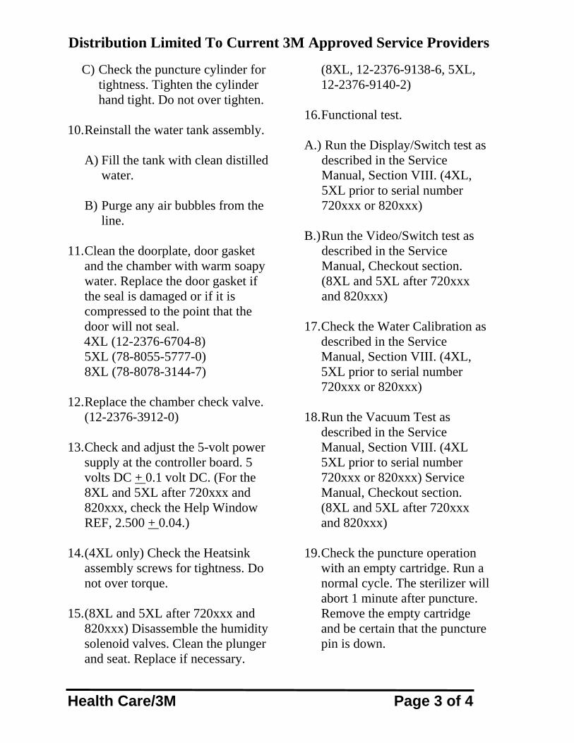
Distribution Limited To Current 3M Approved Service Providers
Health Care/3M Page 3 of 4
C) Check the puncture cylinder for tightness. Tighten the cylinder hand tight. Do not over tighten.
10. Reinstall the water tank assembly.
A) Fill the tank with clean distilled water.
B) Purge any air bubbles from the
line. 11. Clean the doorplate, door gasket
and the chamber with warm soapy water. Replace the door gasket if the seal is damaged or if it is compressed to the point that the door will not seal.
4XL (12-2376-6704-8) 5XL (78-8055-5777-0) 8XL (78-8078-3144-7)
12. Replace the chamber check valve.
(12-2376-3912-0) 13. Check and adjust the 5-volt power
supply at the controller board. 5 volts DC + 0.1 volt DC. (For the 8XL and 5XL after 720xxx and 820xxx, check the Help Window REF, 2.500 + 0.04.)
14. (4XL only) Check the Heatsink
assembly screws for tightness. Do not over torque.
15. (8XL and 5XL after 720xxx and
820xxx) Disassemble the humidity solenoid valves. Clean the plunger and seat. Replace if necessary.
(8XL, 12-2376-9138-6, 5XL, 12-2376-9140-2)
16. Functional test. A.) Run the Display/Switch test as
described in the Service Manual, Section VIII. (4XL, 5XL prior to serial number 720xxx or 820xxx)
B.) Run the Video/Switch test as
described in the Service Manual, Checkout section. (8XL and 5XL after 720xxx and 820xxx)
17. Check the Water Calibration as
described in the Service Manual, Section VIII. (4XL, 5XL prior to serial number 720xxx or 820xxx)
18. Run the Vacuum Test as
described in the Service Manual, Section VIII. (4XL 5XL prior to serial number 720xxx or 820xxx) Service Manual, Checkout section. (8XL and 5XL after 720xxx and 820xxx)
19. Check the puncture operation
with an empty cartridge. Run a normal cycle. The sterilizer will abort 1 minute after puncture. Remove the empty cartridge and be certain that the puncture pin is down.
Distribution Limited To Current 3M Approved Service Providers
Health Care/3M Page 4 of 4
20. (8XL only) Check to be certain all set up information is correct. Run a Trend Printout as described in the Service Manual, Checkout section.
21. (8XL and 5XL after 720xxx and
820xxx) If any sensors have been replaced, check the calibration as described in the Service Manual, Checkout section.
22. Insure that all the service switches are in the normal position by starting a cycle and check for proper initial vacuum. Cancel the cycle with the STOP switch. 23. Seal the sterilizer with the wire seal as directed in the Field Service Reference Manual.
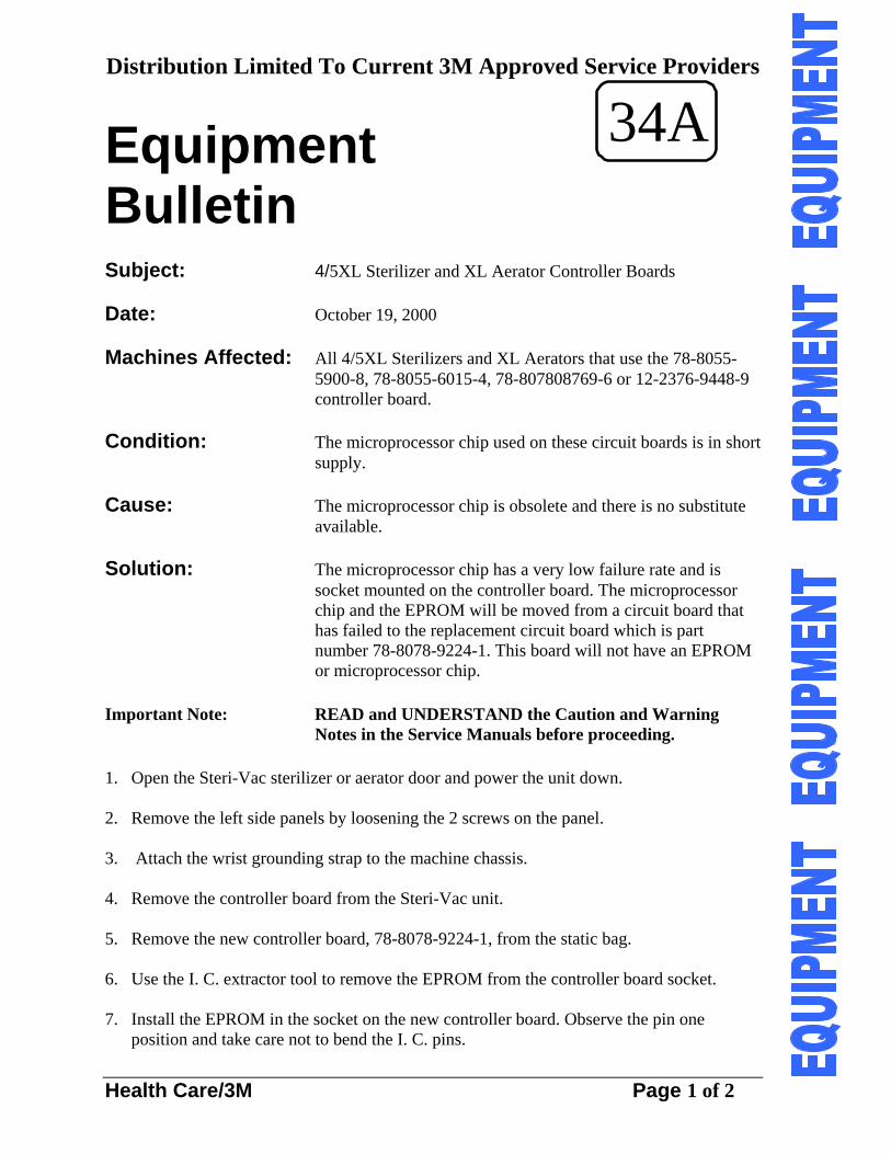
Distribution Limited To Current 3M Approved Service Providers
Health Care/3M Page 1 of 2
Equipment
34A Bulletin Subject: 4/5XL Sterilizer and XL Aerator Controller Boards Date: October 19, 2000 Machines Affected: All 4/5XL Sterilizers and XL Aerators that use the 78-8055-
5900-8, 78-8055-6015-4, 78-807808769-6 or 12-2376-9448-9 controller board.
Condition: The microprocessor chip used on these circuit boards is in short
supply. Cause: The microprocessor chip is obsolete and there is no substitute
available. Solution: The microprocessor chip has a very low failure rate and is
socket mounted on the controller board. The microprocessor chip and the EPROM will be moved from a circuit board that has failed to the replacement circuit board which is part number 78-8078-9224-1. This board will not have an EPROM or microprocessor chip.
Important Note: READ and UNDERSTAND the Caution and Warning
Notes in the Service Manuals before proceeding. 1. Open the Steri-Vac sterilizer or aerator door and power the unit down. 2. Remove the left side panels by loosening the 2 screws on the panel. 3. Attach the wrist grounding strap to the machine chassis. 4. Remove the controller board from the Steri-Vac unit. 5. Remove the new controller board, 78-8078-9224-1, from the static bag. 6. Use the I. C. extractor tool to remove the EPROM from the controller board socket. 7. Install the EPROM in the socket on the new controller board. Observe the pin one
position and take care not to bend the I. C. pins.
Distribution Limited To Current 3M Approved Service Providers
Health Care/3M Page 2 of 2
8. Use the I.C. extractor tool to remove the microprocessor chip from the controller board
socket. 9. Install the microprocessor chip in the socket on the new controller board. . Observe the
pin one position and take care not to bend the I. C. pins. 10. Perform a functional test of the machine to be certain that all features work properly. 11. Replace the side panel and return the sterilizer to service.
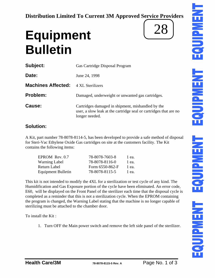
Distribution Limited To Current 3M Approved Service Providers
Health Care/3M 78-8078-8115-5 Rev. A Page No. 1 of 3
Equipment 28 Bulletin Subject: Gas Cartridge Disposal Program Date: June 24, 1998 Machines Affected: 4 XL Sterilizers Problem: Damaged, underweight or unwanted gas cartridges. Cause: Cartridges damaged in shipment, mishandled by the
user, a slow leak at the cartridge seal or cartridges that are no longer needed.
Solution: A Kit, part number 78-8078-8114-5, has been developed to provide a safe method of disposal for Steri-Vac Ethylene Oxide Gas cartridges on site at the customers facility. The Kit contains the following items: EPROM Rev. 0.7 78-8078-7603-8 1 ea. Warning Label 78-8078-8116-0 1 ea. Return Label Form 6550-862-F 1 ea. Equipment Bulletin 78-8078-8115-5 1 ea. This kit is not intended to modify the 4XL for a sterilization or test cycle of any kind. The Humidification and Gas Exposure portion of the cycle have been eliminated. An error code, E60, will be displayed on the Front Panel of the sterilizer each time that the disposal cycle is completed as a reminder that this is not a sterilization cycle. When the EPROM containing the program is changed, the Warning Label stating that the machine is no longer capable of sterilizing must be attached to the chamber door. To install the Kit :
1. Turn OFF the Main power switch and remove the left side panel of the sterilizer.
Distribution Limited To Current 3M Approved Service Providers
Health Care/3M 78-8078-8115-5 Rev. A Page No. 2 of 3
2. While wearing your static grounding strap, locate and remove the EPROM from
the sterilizer controller board place it in a safe place so that it can be reused.
3. Locate the EPROM in the Kit and carefully install it in the controller board. Place all the DIP switched to the OFF or down position. If an abator is installed, keep DIP switch 6 in the ON or up position.
4. Locate the Warning Label in the Kit and install it on the chamber door.
5. Turn ON the Main Power. The machine should start up in a normal manner and
the Rev. level of the EPROM, 0.7, will be displayed on the Display Panel.
6. Open the chamber door and remove all the contents. Install the cartridge to be disposed of in the cartridge well. Be certain that the cartridge is securely seated under the cartridge bracket.
7. Close the door and start a cycle as normal. It will take about 1 hour to complete
the disposal cycle.
8. When the cycle is complete and the door is unlocked, open the door and press Stop. This will clear out the E60 error and reset the logic for the next cycle.
9. Remove the cartridge form the cartridge well and place it on the bottom of the
chamber.
10. Place the next cartridge in the cartridge well and repeat steps 7., 8., 9., and 10 until all the cartridges are disposed of. The cartridges can remain in the chamber to be aerated or they can be moved to an aerator. Three hours of aeration should be sufficient to purge the gas from the empty cartridges.
11. When all the cartridges are disposed of , turn OFF the Main Power Switch and
remove the Kit EPROM from the sterilizer controller.
12. Install the original EPROM in the controller socket. Set the DIP switches to the original position. Turn the sterilizer Main Power ON.
13. Remove the Label from the chamber door. Perform an Accelerated Cycle Test as
described in the 4XL Service Manual on page 8-3 to be certain all functions of the sterilizer work. Place all the dip switches in their original position.
Distribution Limited To Current 3M Approved Service Providers
Health Care/3M 78-8078-8115-5 Rev. A Page No. 3 of 3
14. Replace the left side panel. 15. Return the EPROM and the Warning Label to the Kit box and seal it. 16. Attach the Return Label to the box and return it by the fastest means.
If the sterilizer is used with a catalytic type abatement system, the number of cartridges disposed of can affect the life of the catalytic beds. One or 2 boxes of gas will have a negligible affect on the catalyst but 1 or 2 cases of gas can have a significant affect. When cases of gas are involved, it would be a good practice to measure the EO content in the abator exhaust at the first and at the last disposal cycle. If the exhaust EO content is 3 parts per million or greater, the catalytic bed must be replaced.
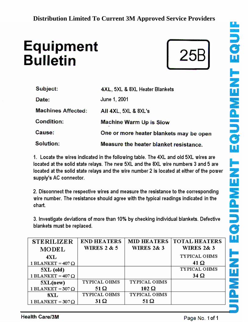
Distribution Limited To Current 3M Approved Service Providers
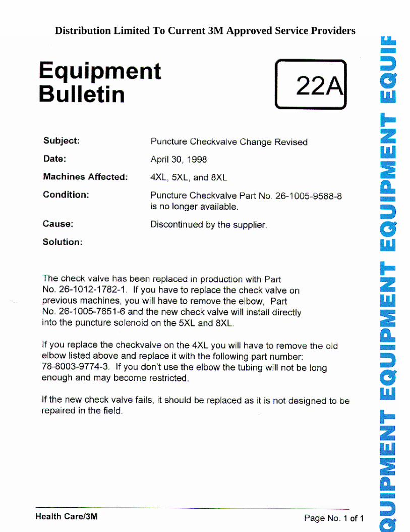
Distribution Limited To Current 3M Approved Service Providers
Distribution Limited To Current 3M Approved Service Providers
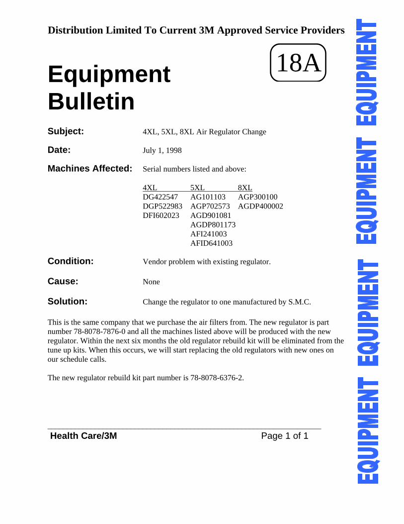
Distribution Limited To Current 3M Approved Service Providers
Equipment 18A Bulletin Subject: 4XL, 5XL, 8XL Air Regulator Change Date: July 1, 1998 Machines Affected: Serial numbers listed and above: 4XL 5XL 8XL DG422547 AG101103 AGP300100 DGP522983 AGP702573 AGDP400002 DFI602023 AGD901081 AGDP801173 AFI241003 AFID641003 Condition: Vendor problem with existing regulator. Cause: None Solution: Change the regulator to one manufactured by S.M.C. This is the same company that we purchase the air filters from. The new regulator is part number 78-8078-7876-0 and all the machines listed above will be produced with the new regulator. Within the next six months the old regulator rebuild kit will be eliminated from the tune up kits. When this occurs, we will start replacing the old regulators with new ones on our schedule calls. The new regulator rebuild kit part number is 78-8078-6376-2. _____________________________________________________________________ Health Care/3M Page 1 of 1
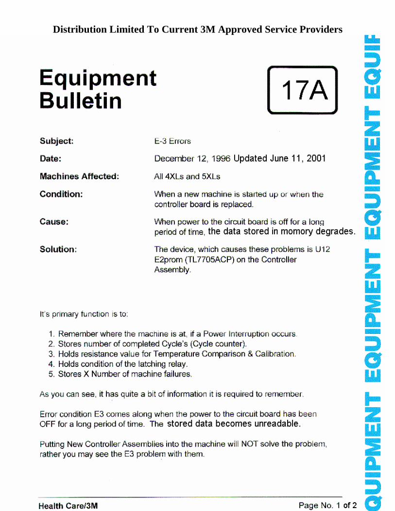
Distribution Limited To Current 3M Approved Service Providers
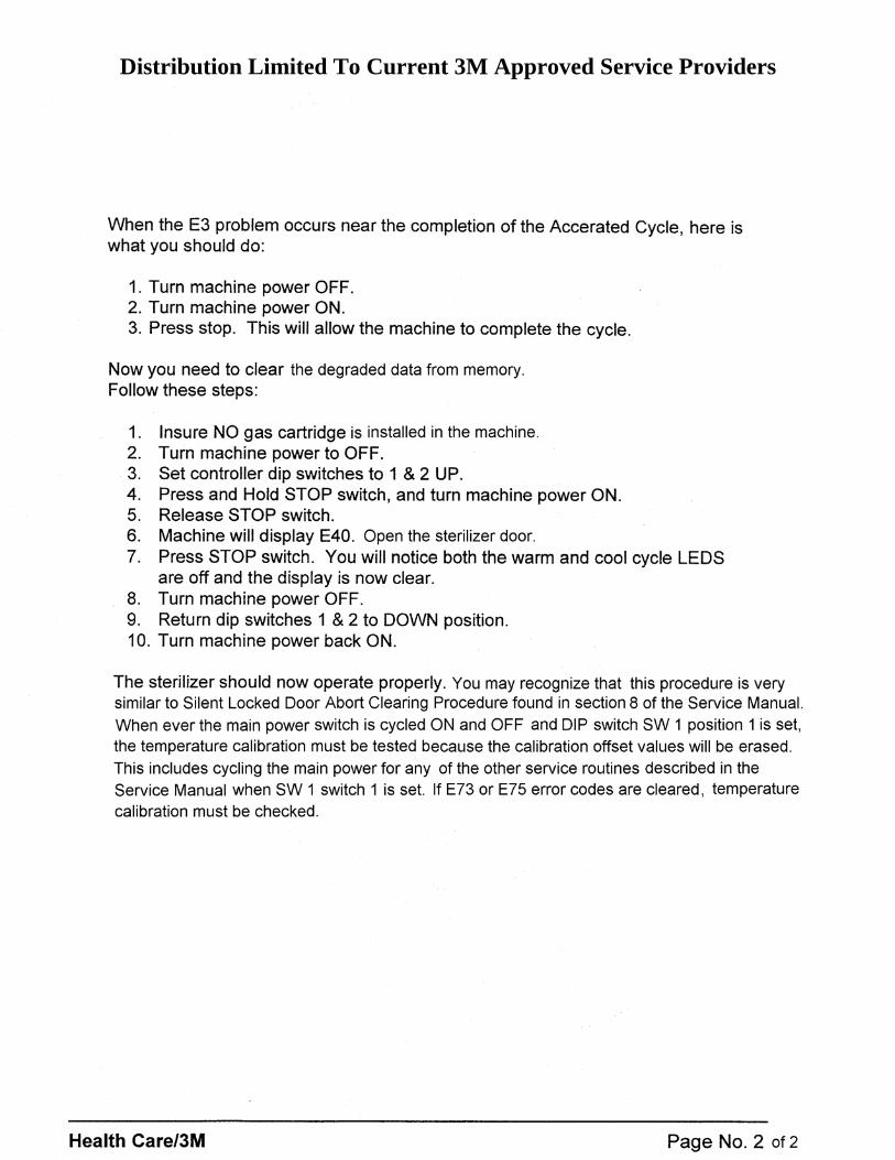
Distribution Limited To Current 3M Approved Service Providers
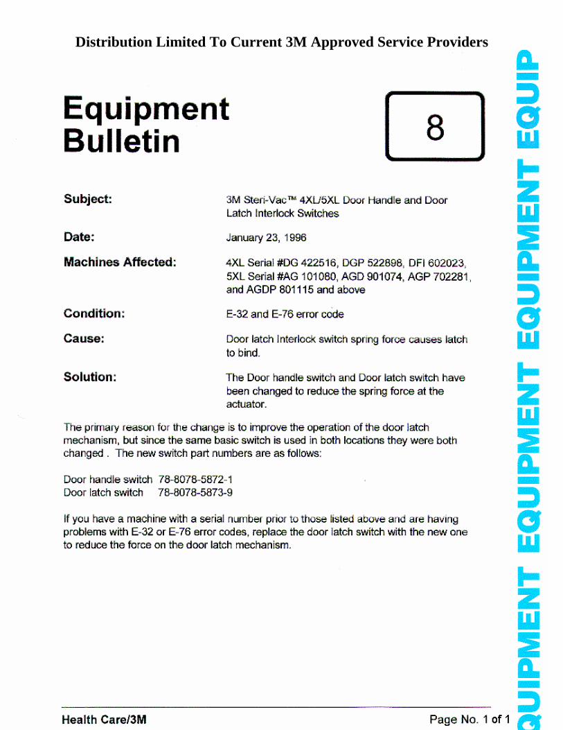
Distribution Limited To Current 3M Approved Service Providers
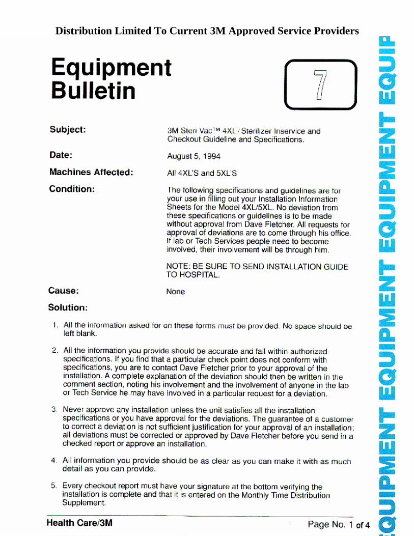
Distribution Limited To Current 3M Approved Service Providers
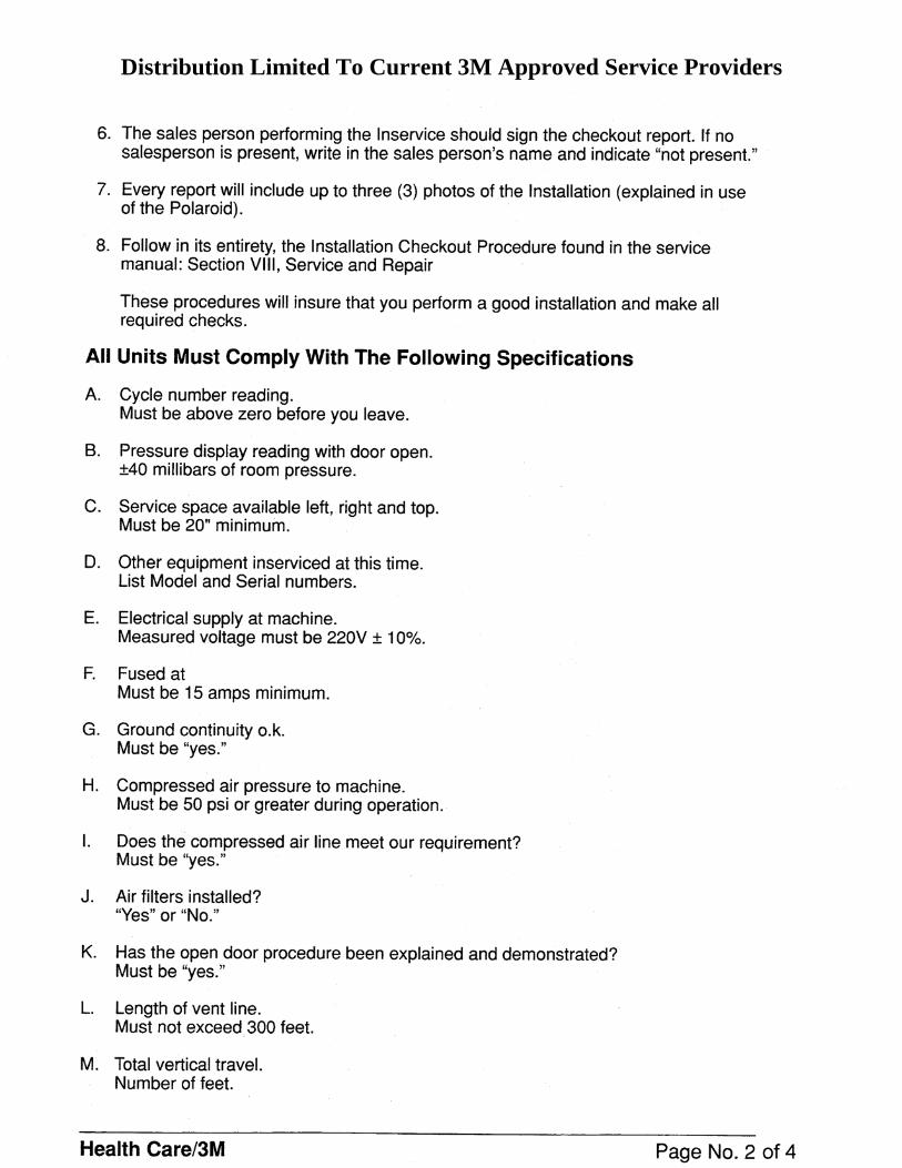
Distribution Limited To Current 3M Approved Service Providers
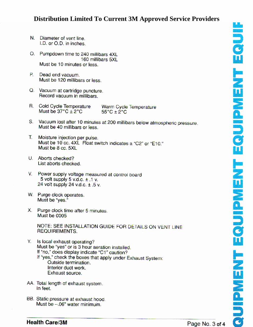
Distribution Limited To Current 3M Approved Service Providers
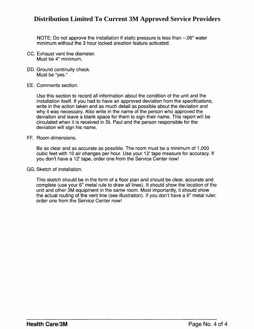
Distribution Limited To Current 3M Approved Service Providers
Distribution Limited To Current 3M Approved Service Providers
Distribution Limited To Current 3M Approved Service Providers
Distribution Limited To Current 3M Approved Service Providers
Distribution Limited To Current 3M Approved Service Providers