Embed Size (px)
Citation preview
w w w . g a l t r o n i c s . c o m
Copyright © 2021 – Galtronics Corporation Ltd.Proprietary Information. All rights reserved. Galtronics reserves the right to modify or amend any antenna or specification without prior notice.
RFD
#: 7
277
; Rev
isio
n: R
5 ; R
elea
se D
ate:
Janu
ary
21, 2
021;
4’ 24-Port 4x4 MIMO Narrow 6-Beam High Gain Directional Panel Antenna [1695-2360 MHz]
Description:• 4x4 MIMO 6-beam high gain Antenna for high capacity stadium/
venue or special event applications
• Very narrow beamwidths - 10.3° AZ/13.6° EL (average) across
band for high sector selectivity
• Patent Pending technology allows for exceptional UL/DL beam
tracking repeatability & stability
• Fixed Electrical Downtilt of 6° per each 4x4 MIMO beams
• Provided with heavy duty top/bottom caps and heavy duty
transport case to prevent damage with multiple deployments
• Excellent alternative to traditional multi-beam antennas
Electrical Specifications
Frequency Band [MHz] 1695-1910 1930-2020 2110-2200 2305-2360
Gain, max. (dBi) 20.1 20.3 20.7 21.1
Gain, avg. (dBi) 18.4 19.0 19.3 19.2
Azimuth Beam Width, 3dB (°) 11.5 10.6 9.9 9.2
Azimuth Beam Width, 10dB (°) 20.0 18.5 17.2 16.1
Azimuth Beam Spacing (°) 16.3 16.1
Azimuth Beam Crossover (dB) 7.5 8.9 10.4 11.7
Elevation Beam Width, 3dB (°) 15.4 14.1 13.1 11.9
Elevation Beam Width, 10dB (°) 26.8 24.3 22.6 20.6
Electrical Downtilt (°) 6 FET (per each 4x4 beam cluster)
First Upper Sidelobe Suppression (dB) 22 20 20 22
Front-to-Back Ratio, 180° (dB) 38 38 38 36
Cross-Polar Discrimination at Boresight (dB) 21 26 26 26
VSWR (max.) / RL (min.) (dB) 1.4:1 / 15.6 1.3:1 / 17.7
Port-to-Port Isolation, Intrabeam* (dB, min.) 30 28
Port-to-Port Isolation, Interbeam** (dB, min.) 18 19 21
PIM @ 2x43 dBm, dBc (max.) -153
Max Power per Port (W) 100
Polarization (°) Dual slant 45 (±45)
Impedance (Ω) 50
GP5124-07277
1695-2360 MHz 6-Beam 4x4 MIMO Multibeam Directional Panel Antenna
Electrical Specifications - BASTA
Frequency Band [MHz] 1695-1910 1930-2020 2110-2200 2305-2360
Gain Over All Tilts, avg. (dBi) 18.4 19.0 19.3 19.2
Gain Over All Tilts Tolerance (dB) 1.3 1.3 1.3 2.0
AZ Beamwidth Tolerance (°) 1.7 1.8 1.9 1.7
EL Beamwidth Tolerance (°) 1.3 0.5 0.5 0.5
Upper Sidelobe Suppression, Peak to +20° (dB) 20.8 17.8 16.8 17.3
Front-to-Back Ratio, Total Power, +/-30° (dB) 26.1 25.7 24.0 22.7
Cross-Polar Discrimination at Boresight (dB) 16.0 18.4 19.1 19.1
* Port-port isolation between each cluster of four ports in the same 4x4 MIMO beam** Port-port isolation between any combination of ports between different beams
w w w . g a l t r o n i c s . c o m
Copyright © 2021 – Galtronics Corporation Ltd.Proprietary Information. All rights reserved. Galtronics reserves the right to modify or amend any antenna or specification without prior notice.
RFD
#: 7
277
; Rev
isio
n: R
5 ; R
elea
se D
ate:
Janu
ary
21, 2
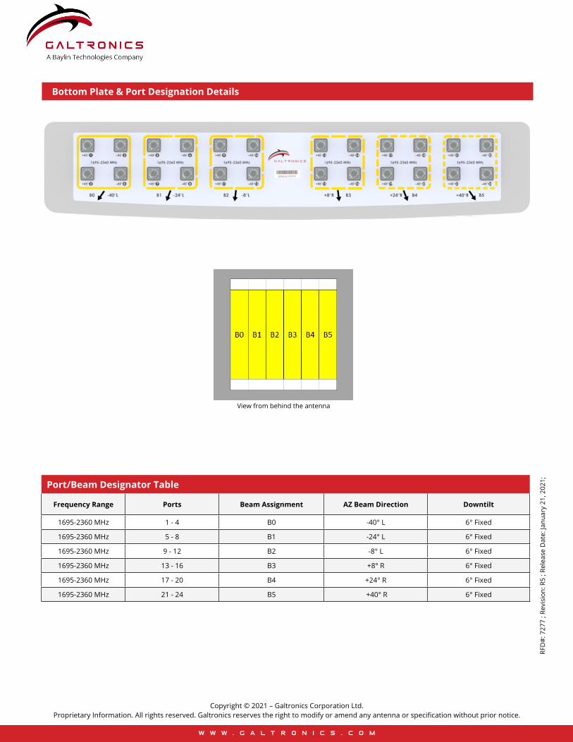
021;Port/Beam Designator Table
Frequency Range Ports Beam Assignment AZ Beam Direction Downtilt
1695-2360 MHz 1 - 4 B0 -40° L 6° Fixed
1695-2360 MHz 5 - 8 B1 -24° L 6° Fixed
1695-2360 MHz 9 - 12 B2 -8° L 6° Fixed
1695-2360 MHz 13 - 16 B3 +8° R 6° Fixed
1695-2360 MHz 17 - 20 B4 +24° R 6° Fixed
1695-2360 MHz 21 - 24 B5 +40° R 6° Fixed
Bottom Plate & Port Designation Details
View from behind the antenna
w w w . g a l t r o n i c s . c o m
Copyright © 2021 – Galtronics Corporation Ltd.Proprietary Information. All rights reserved. Galtronics reserves the right to modify or amend any antenna or specification without prior notice.
RFD
#: 7
277
; Rev
isio
n: R
5 ; R
elea
se D
ate:
Janu
ary
21, 2
021;
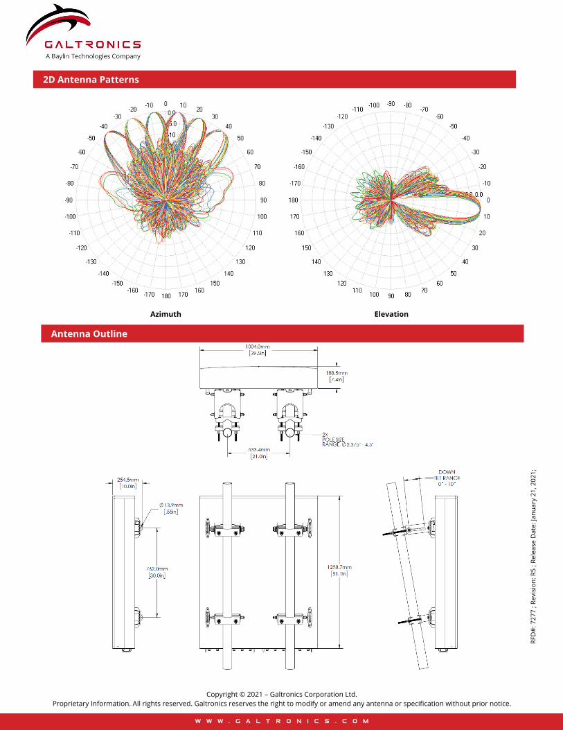
Antenna Outline
2D Antenna Patterns
Azimuth Elevation
w w w . g a l t r o n i c s . c o m
Copyright © 2021 – Galtronics Corporation Ltd.Proprietary Information. All rights reserved. Galtronics reserves the right to modify or amend any antenna or specification without prior notice.
RFD
#: 7
277
; Rev
isio
n: R
5 ; R
elea
se D
ate:
Janu
ary
21, 2
021;
Part Numbers & Ordering OptionsDescription Color Mounting Kit Part Number
4x4 MIMO Narrow 6-Beam Directional Panel Antenna, 6° FET with 24x 4.3-10 (F) Connectors and Heavy Duty Transport Case Gray Includes 2x MK-06989 mounting kit
assemblies GP5124-07277-112
Mechanical SpecificationsOperating Temperature -40° to 158°F (-40° to +70°C)
Antenna Weight 70 lbs (31.8 kg)
Antenna Bracket Weight 13.4 lbs (6.1 kg), 2x Brackets Per Antenna
Antenna Dimension (Height x Width x Depth) 51.1” (1298.7 mm) x 39.5” (1004.0 mm) x 7.4” (188.5 mm)
Input Connector Type 24x 4.3/10 (F)
Radome Material ASA w/Heavy Duty Top/Bottom Caps
Radome Color Gray
Wind Load, Front (@ 150 km/h) 1666 N / 375 lbf
Wind Load, Side (@ 150 km/h) 364 N / 82 lbf
Wind Load, Maximum (@ 150 km/h) 1695 N / 381 lbf
Wind Survival Rating 150 mph (241 km/h)
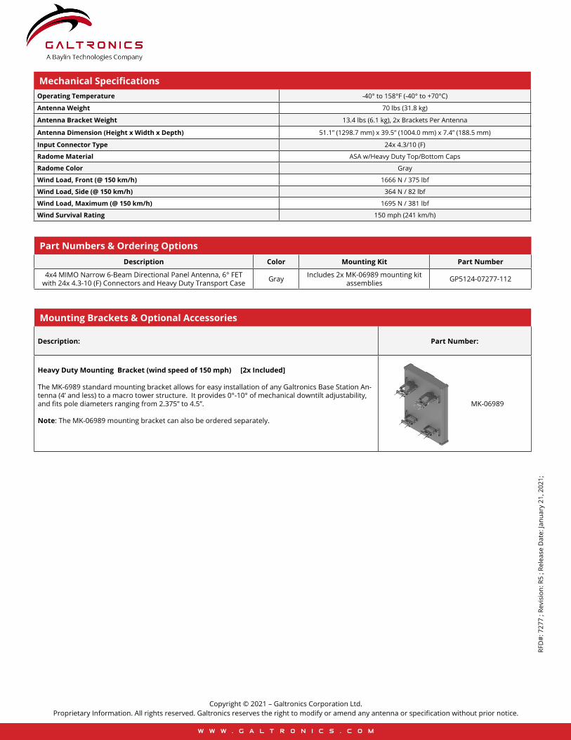
Mounting Brackets & Optional Accessories
Description: Part Number:
Heavy Duty Mounting Bracket (wind speed of 150 mph) [2x Included]
The MK-6989 standard mounting bracket allows for easy installation of any Galtronics Base Station An-tenna (4’ and less) to a macro tower structure. It provides 0°-10° of mechanical downtilt adjustability, and fits pole diameters ranging from 2.375” to 4.5”.
Note: The MK-06989 mounting bracket can also be ordered separately.
MK-06989