Embed Size (px)
Citation preview
4-4187 59 "C "A ICIMG Il
9NCLSUFID F/G IV/& "
L2. 2,L 2
MICROCOPY RESOLUTION TEST CHART
NA[,N L'.U11N ~ p ~ 4
N4RL-R-1068 AR-005-148
* lUM FILE COPYDEPARTMENT OF DEFENCE
DEFENCE SCIENCE AND TECHNOLOGY ORGANISATION
MATERIALS RESEARCH LABORATORIES
MELBOURNE, VICTORIA
01
REPORT
00 NRL-R-1068i'-
IO PERFORMANCE OF A DIGITAL REAL TIME RADIOGRAPHIC
*IMAGING SYSTEM
T M.J. Chung
JAN U 6 1988".'
Approved for Public Release
DSTO iDSTBYRON ~Com-onweath of Aostraiia
MARIYRONGJUE 1987
r- U.:rU" 31' *r*-S NAT1O'.AL
TECrHlC'Al iN MTKO 3RVICE
.5 ur~~~s~'TOREPRUiTUGE AND~ SEL THMIS REPORT
DEPARTMENT OF DEFENCE
MATERIALS RESEARCH LABORATORIES
REPORT
MRL-R-1068
PERFORMANCE OF A DIGITAL REAL TIME RADIOGRAPHIC
IMAGING SYSTEM
M.J. Chung
ABSTRACT
This report examines the radiographic and electro-optical
characteristics of a digital, real-time radiographic imaging system. :t W3S
found that;
a. for optimum X-ray magnifications the television camera tube inthe system has a significant effect on image quality and
b. large variations in X-ray tube voltage may be tolerated beforeimage degradation prevents successful computer image processing.
This work forms part of a study on a computer-aided Inspectionprocess.
Approved for Public Release
POSTAL ADDRESS: Director. Materials Reeearch LaboratoriesP.O. Box S0. Ascot Vit. Victoria 3032. Australia
CONTENTS
Page No.
1. INTRODUT'ION 1
2. BACKGROUND 1
2.1 X-Ray Imaglng 2
2.2 Feature Size 3
2.3 Electro-Optical Imaging 4
2.4 Digltal Imaging 4
3. MEASUREMENTS AND DISCUSSION 5
3.1 Equipment 5
3.2 X-ray Magnlflcatlon and Radlographic Efficiency 6
3.3 EleCtro-optical ResponSe 7
4. SUMMARY a
5. ACKNOWLEDGEMENTS 8
6. REFERENCES 9
APPENDIX A .1
APPENDIX B
PERFORMANCE OF A DIGITAL REAL TIME RADIOGRAPHIC
IMAGING SYSTEM
I. INTRODUCTION
Conventional film radiography produces images of high resolution andlarge contrast range that are suitable for visual inspection. However, inmunitions production where large numbers of items are to be inspected, filmradiography is expensive, time consuming and subject to operator fatigue anderror. Such errors in the Inspection of munitions can result in hazardoussituations that could result in malfunctions during storage and use.
Real-time radiographic techniques have been available for some timeIll but the image quality produced by this method has been inferior to that offilm radiography. However, Improvements in image intensifiers together withthe use of digital Image processing techniques now provide good quality imageswhich give an attractive alternative to the film radiographic process. Thesenew methods have the potential to avoid many of the disadvantages of thepresent inspection process and may be readily adapted to automatic inspectionwith the consequent reduction In inspection errors.
This report examines the radiographic and electro-opticalcharacteristics of a digital real-time radiographic imaging system which hasbeen successfully applied to the inspection of fuze assemblies in thelaboratory. The images produced are in a form suitable for computerprocessing and will be the subject of a later report.
2. BACKGROUND
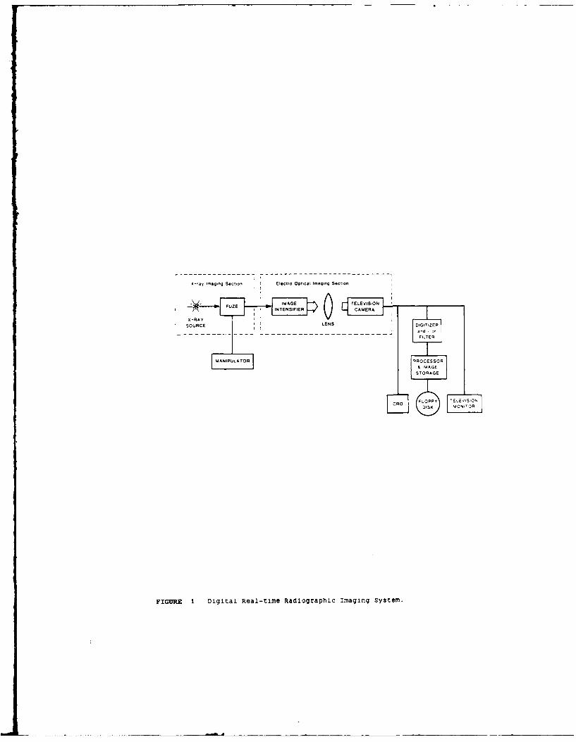
A block diagram of the equipment used to produce digitized real-timeradiographic images is shown in Figure 1. The system consists of acontinuous X-ray source, a manipulator to accurately position the object under
examination, an X-ray image intensifier with collimating lens to convert theX-ray images to visual images and a television camera with lens to view theimage. The output from the television camera is digitized and stored on afloppy disk in a format suitable for processing by computer.
The final image produced by this system is affected by thecharacteristics of both the X-ray and the electro-optical imaging sections.These characteristics, together with system noise, reduce the number ofdistinguishable grey levels In the image [21. In this report, the X-rayimaging section in Figure 1 is taken as the X-ray source and X-ray sensitiveinput screen of the image intensifier whilst the electro-optical imagingsection comprises the image intensifier, lens and television camera.
Image quality from this real-time radiographic system may be definedin terms of radiographic efficiency and spatial resolution. Radiographicefficiency is the conventional method 13] for describing the ability todistinguish between contrast levels and Is defined as the ratio of thesmallest perceptible material thickness increment In the object to the totalthickness. The efficiency may be measured with DIN IQI gauges [31 of amaterial similar to that of the object. The spatial resolution of the systemis its ability to discriminate between near-by features which have the samecontrast in the image plane. It may be measured in terms of the ContrastTransfer Function (CTF) or the Modulation Transfer Function (MTF) 11,4). Thefactors affecting image quality are discussed below in more detail under theheadings of -X-ray Imaging* and "Electro-optical Imaging*.
2.1 X-ray LaqIng
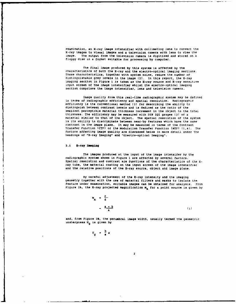
The images produced at the input of the image intensifer by theradiographic system shown in Figure I are affected by several factors.Spatial resolution and contrast are functions of the characteristics of the X-ray tube, the material coating on the input screen of the image Intensifierand the relative positions of the X-ray source, object and image plane.
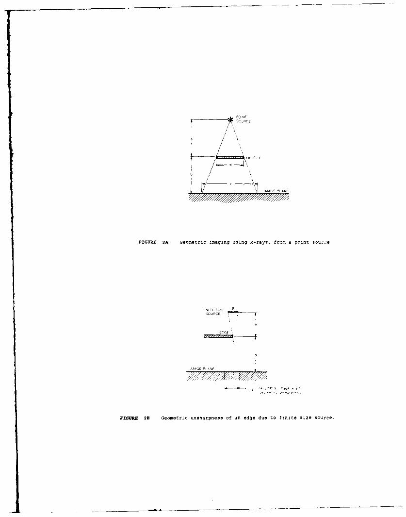
By careful adjustment of the X-ray intensity and the imaginggeometry together with the use of material filters and masks to isolate thefeature under examination, suitable images can be obtained for analysis. FromFigure 2A, the X-ray projected magnification Mx for a point source is given by
M Cx d
a+b i
a
and, from Figure 28, the penumbral image width, usually termed the geometricunsharpness Ug Is given by
U - bg a
2
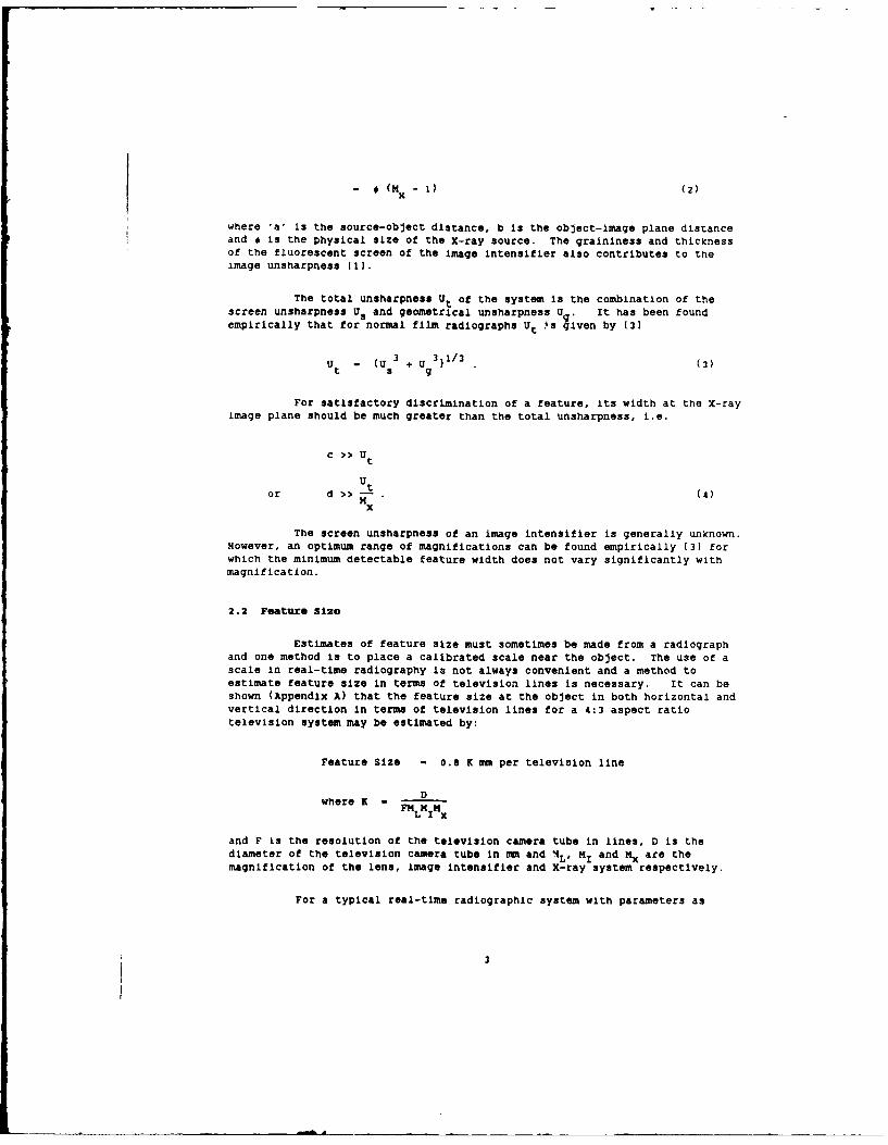
- * (Mx - 1) (2)
where 'a' Is the source-object distance, b is the object-image plane distanceand # is the physical size of the X-ray source. The graininess and thicknessof the fluorescent screen of the image intensifier also contributes to theimage unsharpness (1).
The total unsharpness Ut of the system is the combination of thescreen unsharpness Us and geometrical unsharpness Ug. It has been foundempirically that for normal film radiographs Ut
4s given by (31
- (U + U 3)1/3 (3)
For satisfactory discrimination of a feature, its width at the X-rayimage plane should be much greater than the total unsharpness, i.e.
c >> Utut
or d >>-. (4)Mx
The screen unsharpness of an image intensifier is generally unknown.However, an optimum range of magnifications can be found empirically (31 forwhich the minimum detectable feature width does not vary significantly withmagnification.
2.2 Feature Size
Estimates of feature size must sometimes be made from a radiographand one method Is to place a calibrated scale near the object. The use of ascale in real-time radiography is not always convenient and a method toestimate feature size in terms of television lines is necessary. It can beshown (Appendix A) that the feature size at the object in both horizontal andvertical direction in terms of television lines for a 4:3 aspect ratiotelevision system may be estimated by:
Feature Size - 0.8 K mm per television line
Dwhere K - FML I H
and F is the resolution of the television camera tube In lines, D is thediameter of the television camera tube in mm and 4L' MI and Mx are the
magnification of the lens, image intensifier and X-ray system respectively.
For a typical real-time radiographic system with parameters as
3
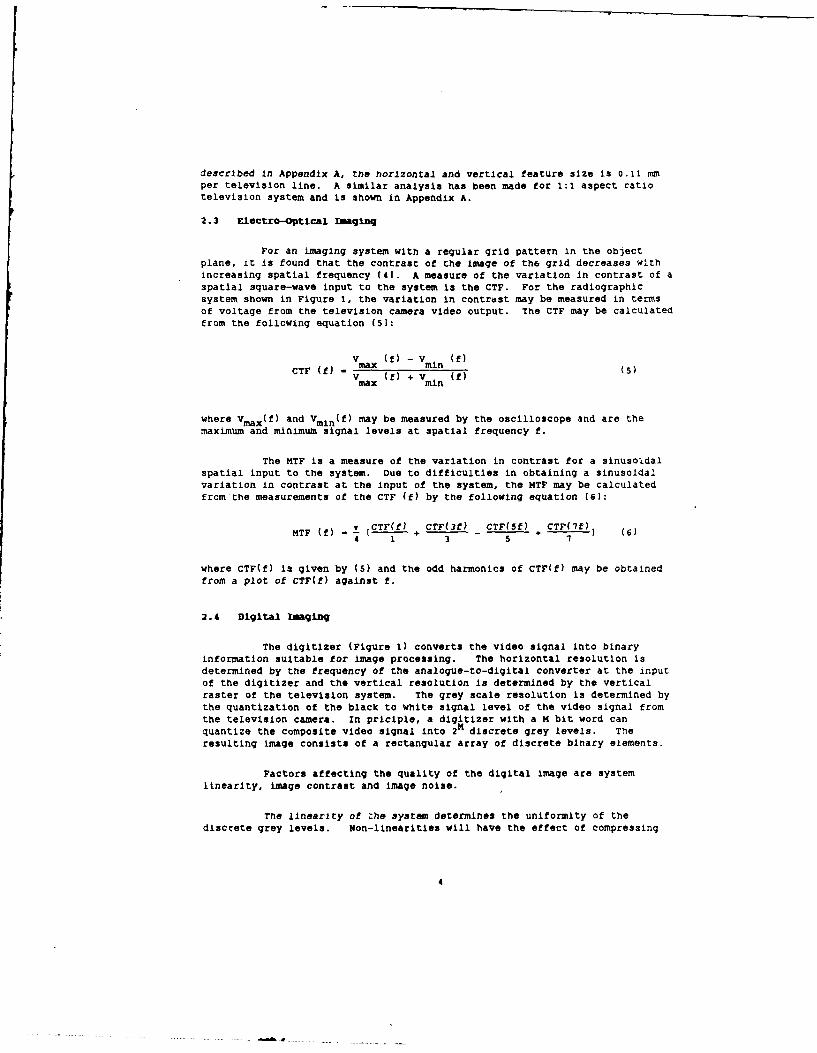
described in Appendix A, the horizontal and vertical feature size is 0.11 mper television line. A similar analysis has been made for 1:1 aspect ratiotelevision system and Is shown in Appendix A.
2.3 Electro-Optical Imaginq
For an imaging system with a regular grid pattern in the objectplane, it is found that the contrast of the image of the grid decreases withincreasing spatial frequency (41. A measure of the variation in contrast of aspatial square-wave input to the system Is the CTF. For the radiographicsystem shown in Figure 1, the variation in contrast may be measured in termsof voltage from the television camera video output. The CTF may be calculatedfrom the following equation (51:
v (U - (U)
CTF (f) - ax ( m) ()
vmax (f) + Vmi n (f)
where Vmax(f) and Vmln(f) may be measured by the oscilloscope and are themaximum and minimum signal levels at spatial frequency f.
The MTF is a measure of the variation in contrast for a sinusoldalspatial input to the system. Due to difficulties In obtaining a sinusoidalvariation in contrast at the input of the system, the MTF may be calculatedfrom the measurements of the CTF (f) by the following equation [6):
MTF (f) - CTFf+ CTF(3f) CTF(5f) CTF(Tf) (L4Ff)- 1 + 3 - 5 + 1 1 Cs
where CTF(f) is given by (5) and the odd harmonics of CTF(f) may be obtainedfrom a plot of CTF(f) against f.
2.4 Digital tIaginq
The digitizer (Figure 1) converts the video signal into binaryinformation suitable for image processing. The horizontal resolution isdetermined by the frequency of the analogue-to-digital converter at the inputof the digitizer and the vertical resolution is determined by the verticalraster of the television system. The grey scale resolution Is determined bythe quantization of the black to White signal level of the video signal fromthe television camera. In priciple, a digitizer with a 1 bit word canquantize the composite video signal into 2 discrete grey levels. Theresulting image consists of a rectangular array of discrete binary elements.
Factors affecting the quality of the digital image are systemlitnearlty, image contrast and image noise.
The linearity of the system determines the uniformity of thediscrete grey levels. Non-linearities will have the effect of compressing
* . .... .... .. . ... .... k 1 . .. . ... . . .. .. . .... ... . .4
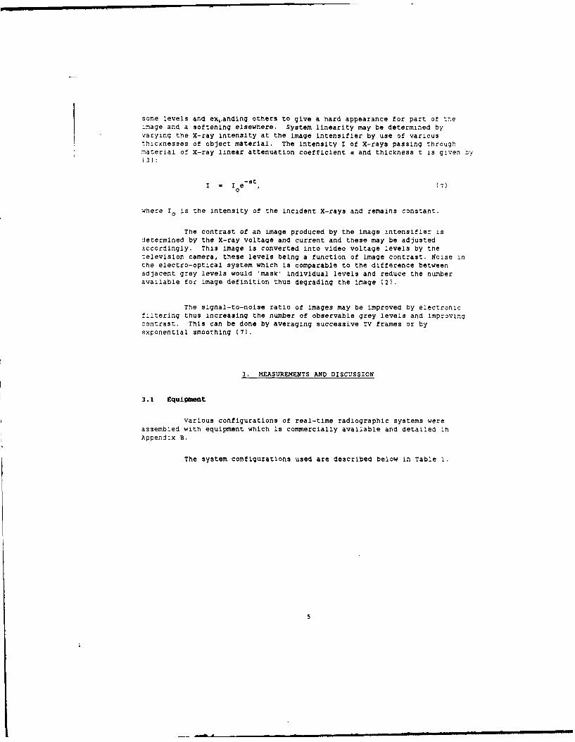
some levels and exLanding others to give a hard appearance for part of theimage and a softening elsewhere. System linearity may be determined byvarying the X-ray intensity at the image intensifier by use of variousthicknesses of object material. The intensity I of X-rays passing throughmaterial of X-ray linear attenuation coefficient a and thickness t is given zy
3]:
I - I e , (7)
where Io is the intensity of the incident X-rays and remains constant.
The contrast of an image produced by the image Intensifier isdetermined by the X-ray voltage and current and these may be adjustedaccordingly. This image Is converted into video voltage levels by thetelevision camera, these levels being a function of image contrast. Noise inthe electro-optical system which is comparable to the difference betweenadjacent grey levels would 'mask' individual levels and reduce the numberavailable for image definition thus degrading the image 12).
The signal-to-noise ratio of images may be improved by electronicfiltering thus increasing the number of observable grey levels and improvingcontrast. This can be done by averaging successive TV frames or byexponential smoothing (71.
3. MEASUREMENTS AND DISCUSSION
3.1 Equipment
Various configurations of real-time radiographic systems wereassembled with equipment which is commercially available and detailed inAppendix B.
The system configurations used are described below in Table I.
5
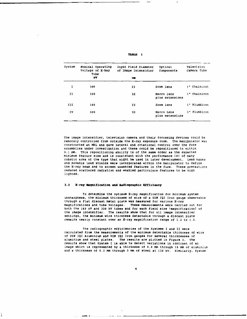
TABLE 1
System Nominal Operating Input Field Diameter Optical TelevisionVoltage of X-Ray of Image Intensifier Components Camera Tube
Tubekv ,a
I 160 23 Zoom lens I" Chalnicon
II 320 32 Macro lens 1" Chalniconplus extensions
III 160 23 Zoom lens 1" Plumbicon
IV 320 32 Macro Lens I" Plumbiconplus extensions
The image intensifier, television camera and their focussing devices could beremotely controlled from outside the X-ray exposure room. The manipulator wasconstructed at MRL and gave lateral and rotational control over the fuzeassemblies under Investigation and these could be repositioned to within0.1 mm. This repositioning ability is of the same order as the expectedminimum feature size and is consistant with the performance (a] of manyrobotic arms of the type that might be used in later development. Lead masksand movable lead shields were incorporated within the manipulator to definethe X-ray beam and to screen unwanted features in the fuze. These precautionsreduced scattered radiation and enabled particulars features to be highlighted.
3.2 X-ray Magnification and Radiographic Efficiency
To determine the optimum X-ray magnification for minimum systemunsharpness, the minimum thickness of wire of a DIN II Iron gauge observablethrough a flat diecast metal plate was measured for various X-raymagnifications and tube voltages. These measurements were carried out forboth the 160 kV and 320 kV tubes and for each field size (magnification) ofthe image intensifier. The results show that for all image Intensifiersettings, the minimum wire thickness detectable through a diecast plateremains nearly constant over an X-ray magnification range of 1.2 to 1.5.
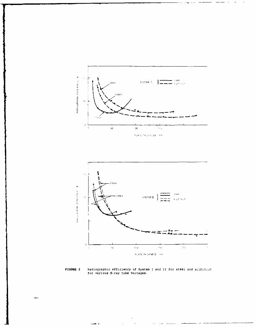
The radiographic efficiencies of the Systems I and II werecalculated from the measurements of the minimum detectable thickness of wireof DIN 101 Aluminium and DIN Il Iron gauges for several thicknesses ofaluminium and steel plates. The results are plitted in Figure 3. Theresults show that System I is able to detect variations in contrast of animage which is represented by a thickness of 0.4 mm through 15 mm of aluminiumand a thickness of 0.3 an through 5 mm of steel at 130 kV. Similarly, System
6
II may detect contrast variations represented by 0.8 mm through 20 mm ofaluminium and 0.6 nu through 5 mm of steel at 240 kV.
3.3 Klectro-Optical Response
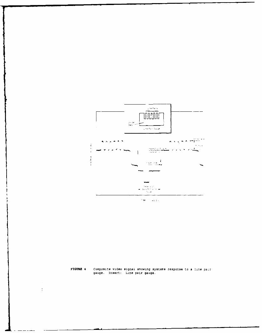
The responses of the four systems were measured with a Tektronix 468digital oscilloscope and recorded on a digital plotter. A sample of theseresults is given in Figure 4 which shows the modulation of the video signaldue to a copper line pair gauge. The background level is the video signallevel produced by the surrounding edges of the copper gauge and the modulationis measured with respect to this level. The measurements of Vmax(f) andVmin(f) used in the calculation of the CTF(f) were made using the average of32 sweeps of the Tektronix CRO.
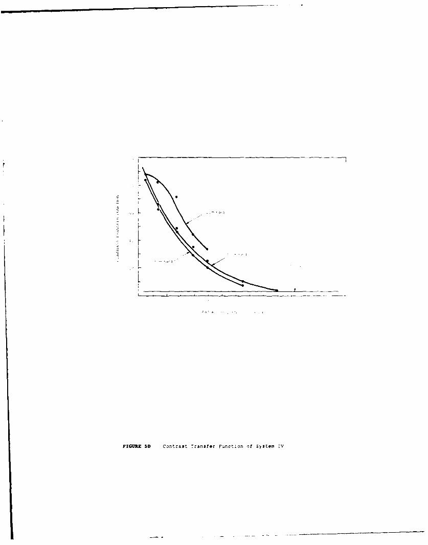
The CTF's for the Systems I and II are plotted in Figures SA and5B. For these systems, the component introducing most image degradation isexpected to be either the image intensifier or the television cameras.Interchanging the television cameras resulted in a greater variation in theresultant CTF than dld interchanging the intensifiers. The response of theSystems III and IV are also shown In Figures 5C and D. Comparison betweenFigures 5A, B, C and D show a reduction of 40% in system CTF occurs when thetelevision camera with the plumbicon tube is used. The limiting CTF for theeye is generally taken as 3% (6), and the response of all of the systemsapproaches this limit at spatial frequencies of 2.0 to 2.5 line pairs permm. The Modulation Transfer Function of the electro-optical system may becalculated from these results, using equation (6).
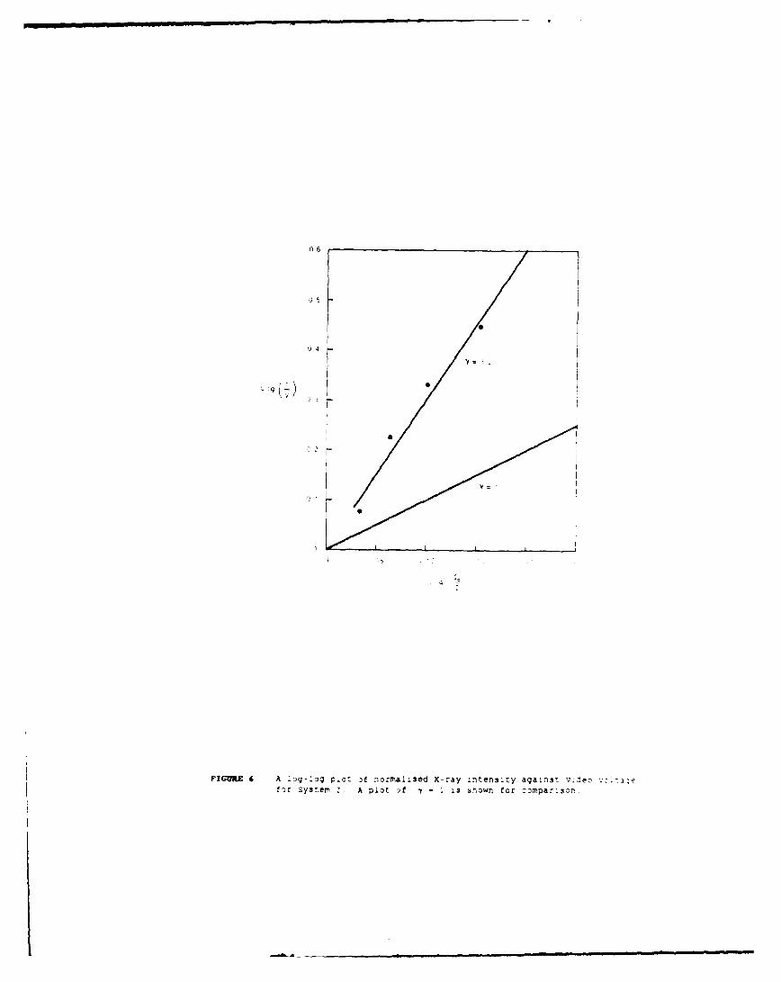
The linearity of System I was measured by attenuating the X-rayintensity with different thicknesses of copper plate. The normalized X-rayintensity I/Io may be calculated from equation (7). The relevant log-log plotis shown in Figure 6. A linear regression curve of best fit shows thatthe y (slope of log-log plot) for the system is 3.0 which is greater than theadjustable range available (0.5 to 1.0) of I for television cameras.Linearity corrections to the digital image would need to be carried out bycomputer processing.
The effect of X-ray tube voltage on image contrast for System I wasdetermined from digitized images at different X-ray voltage levels. Thenumber of grey levels present was measured by means of a grey levelhistogram. The results are given in Figure 7 which shows that a change in X-ray voltage from 80 kV to 135 kV corresponds to an Increase in grey levelsfrom 40 to 167.
The reduction in image noise due to electronic logarithmic filtering17) is shown in Figure 8 which plots the intensity variation along a line ina typical image. An increase In signal-to-noise ratio of 13db can beachieved by such filtering. This corresponds to an increase in grey levelsfrom 68 discrete grey levels in a 'hard' image to 208 continuous grey levelsin the filtered image. The increase in grey levels of an Image isaccompanied by an observed increase in Image quality. This increase in imagequality enhances visual inspection of fuzes but is accompanied by an increaseof up to one minute in the time taken to produce a digital image. For the
7
filters [71 used in this work, the time required increased from 20 s to iminute.
4. SUMMARY
The optimum X-ray Magnifications for the 150kV and 320kV systemsexamined were found to be 1.5 and 1.2 respectively. The radiographicufficiencies of System I and II have been determined for steel and aluminiumfor several X-ray tube voltages. The Contrast Transfer Functions for thefour systems have been measured up to a spatial frequency of 3.0 line pairsper mm. Careful selection of television cameras will improve the ContrastTransfer Functions of the system by up to 40% for midband spatial frequencieswhilst the limit of visual resolution with these systems is expected to be 2.0- 2.5 line pairs per mm. Measurements have shown System I to be non-linearand it is expected that other radiographic systems will have a similarcharacteristic. A method has been described to determine the feature size atthe object plane in terms of TV lines at the monitor.
Day-to-day variations of 5 kv In X-ray tube voltages would not beexpected to have a significant effect on Image quality. Electronic filteringimproves image quality but increases the time taken to produce a digitalimage.
5. ACKNOWLEDGEMENTS
The author wishes to thank Mr G. Cooke for the help in constructingthe manipulator and Mr P. Star for his assistance in carrying out measurementsdescribed in this paper.
6. REFERENCES
1. Bossi, R., Olen, C., and Mengers, P. (1983) "The Non-destructiveTesting Handbook. Real Time Radiography,. American Society forNon-destructive Testing. Columbus, Ohio.
2. Castleman, K.R. (1979). "Digital Image Processing", Prentice-Hall,New Jersey.
3. McMaster, R. (Editor) (1959). *Non-destructive Testing Handbook."The Ronald Press Company, New York.
4. Lucien, M., Biberman, m. and Nudelman, S. (Editors) (1971)."Photoelectronic Imaging Devices", Vol. 1, Plenum Press, New York.
5. Lucien, M., and Nudelman, S. (Editors) (1971). "Photoelectric Imaging
Devices", Vol. 2, Plenum Press, New York.
6. RCA Electro-Optics Handbook (1974) Technical Series EOH-11.
7. Bruggemann, H. -Temporal Filtering using Pixel Incrementing",
SMPTE Journal, August 1981.
8. Exhibitors "ASEA Pty Ltd", "HNI Perkins", "Cybernetics Control Pty Ltd"at "National Conference and exhibition on Robotics", Melbourne,
August 1984.
9. Australian Post Office, Technical Training Publication, (1965)
"Introduction to Television", ETP 0307.
9
k
X-,ay Imag~ng Secton I Electro Ootical Imaging Section
FUZE INTENSIFIER CMR
X-RAY0SOURCE ~LENSDGTIE
I I a. d ,,
MANILAT OR R aOCESS S
FIGURE I Digital Real-time Radiographic Imaging System.
P_ ;OINT'OURCE
OBJECT
~~IMAE PLANE
FIGURE 2A Geometric imaging using X-rays, from a point source
FINIT E SIZESOURCE
DISE
MA3E PL'
FIGURE 2B Geometric unsharpness of an edge due to finite size source.
.32
40"30
4 -
3 IL)
L2O
L
kV
VIE I
FIGURE 3 Radiographic efficiency of System I and II for steel and ai'rnu.for various X-ray tube voltages.
r-- -A,I,
FIGURE 4 composite video signal showing systems response to a line pairgauge. Insert: Line pair gauge.
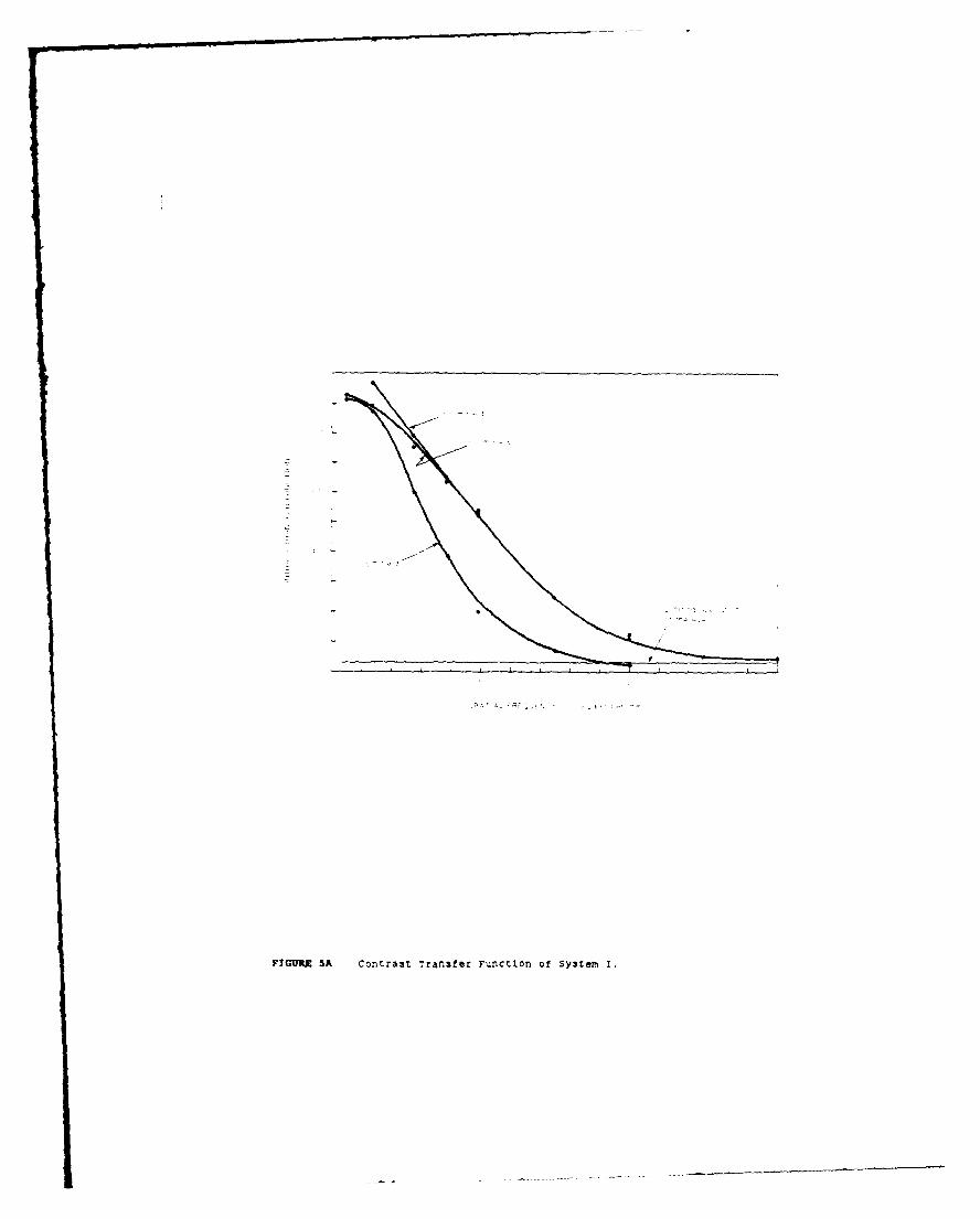
FIGTIR 5A Contra3t Transfer F.anctlon Of SysteMr 1.
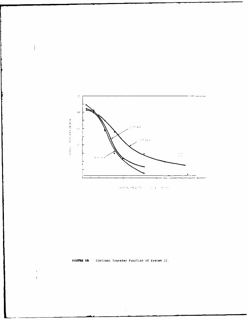
FIGURE 5B Contrast Transfer Function of System II.
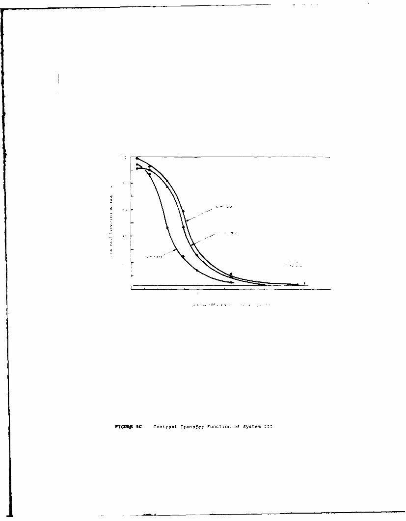
FIGURE SC Contrast Transfer Function of System
F
F -A
r
0
FIGURE SD Contrast ~ranster Punct~on of System :v
52
Y
PIGVRE 6 A -o-:g plot of normalised X-ray intensity against v:-Jeo ':for System :. A plot Df 7 - Iis sh~own for comparison'.
1E 30
3 0
FIGURE 7 Variation of the number of grey levels in a digitized radlograpn.:image with X-ray Tube Voltage.
FIGURE 8 Variation in intensity across a fuze for two different Lteqra .-.levels.
APPENDIX A
There are several image transformations made in the real-timeradiographic system shown in Figure 1. The geometry of the X-ray source,object and intensifier determines the X-ray image projected onto the inputscreen of the image intensifier. The X-ray image intensifier converts theX-ray image to a light image. This image is collmated by a separate lens,focal length fc and magnified by the zoom lens, focal length fz, to beprojected onto the photo sensitive input screen of the television cameratube. This image is scanned by the tube's electron beam and reproduced ryelectronic means on a television monitor. The number of lines used in tescan vary with National standards and with tube type. Because of necessaryelectronic compensations within the television tube, only about 75% of --eselines corresponding to maximum resolution are expected to be accuratelyreproduced ]. The band width of the video amplifier is such that Thehorizontal resolution is at least equal to the number of vertical raster inesof the television tube.
For a radiographic system (Figure i) of X-ray magnificatlon Mx ,image intensifier magnification MI , lens magnification M - fz /fc, atelevision system aspect ratio 4:3, camera tube diameter 0 mm and F elevsI.lines, the horizontal resolution equals the vertical resolution and is ;ivenby:
0.8SDResolution - mm per television line
Similarly, for 1:1 aspect ratio system, the equations become:
4.00Vertical resolution 1-1 per television line,3s2FM M M
1.0D0Horizontal resolution 1 mm per television line
,2FM LM IM
For the radiographic system with aspect ratio 4:3, and Mx -
M 1 - 1/6, ML - 1.45, (f c . 72.4 mm, fz " 104.9 MM), F - 500 lines, 25 ,the vertical and horizontal resolutions are 0.11 mm/line.
APPENDIX B
specifications of Equipment used in the Real-timeRadiographic Systems
I. X-ray Tubes
Norminal Voltage 160 kvFocal Spot 0.4 mm x 0.4 r=
Continuously rated 0.4 mM focus : 4 rAcurrent
Nominal Voltage 320 kVFocal spot 1.2 mm x 1.2 7TIContinuously rated 1.2 mm focus : 4 tA
currentVoltage Constant DC
2. -%age Intensifier Tubes
23 Cm Tube
Operating Modes 1 2 3input Field Diameter (cm) 23 15 10
Typical Resolution (lp/cm) 42 50 53
32 cm Tube
Cperatlng Modes Normal Mi M2
:nput Field Diameter (cm) 32 23Typlcal Resolution lp/cm) 32 36 40
3. ODotical Components
Focal length, collimating lens 23 cm Tube 72.4 mm
Zoom Lens Aperture Ratio/Focal Length 1:2.5/16-I6I rot
80 "m Macro Lens with 70 mm extension tubes
4. Television Cameras
Tube Type 1" ChalniconGamma 0.95Signal to Noise Ratio better than 40db p-p/rms
Tube Type 1" Plumbicon
Gamma 0.95Signal Noist Ratio better than 40 db p-p/rms
5. Television Monitor
Model ElectrochromeType Monochrome EVM 1519 X
SECURr:Y :LASSIFICATION OF TIS PACE UNCLASSIFIED
DOCUMENT CONTROL DATA SHEET
REPCRT NO AR NO REPORT SECURITY CLASS:F::A7::
MRL-R-1068 AR-005-148 Unclassified
_:LE
Performance of a digital real time radiogiaphicimaging system
AUTHOR(S) CORPORATE AUTHOR
Materials Research Laborator-es
M.J. Chung PO Box 50,Ascot Vale, Victoria 3032
REPORT DATE TASK NO SPONSOR
June 1987 ODP 84/091 Office of Defence
Production
FILE NO REFERENCES PAGES
G6/4/8-3298 9 25
CLASSIFICATION/LIMITATION REVIEW DATE CLASSIFICATION/RELEASE AUTHCR:TY
June 1990 Superintendent, MRL
Physics Division
SECONDARY DISTRIBUT1ON
Approved for Public Release
ANNOUNCEMENT
Announcement of this report is unlimited.
KEYWORDS
Radiography Imaging techniques
Radiographic Imaging
Munitions Inspection
SUBJECT GROUPS 0094J 0082B
ABSTRACT
_' This report examines the radiographic and electro.optical
characteristics of a digital, real-time radiographic imaging system. It was
found that;
a. for optimum X-ray magnifications the television camera tube inthe system has a significant effect on image quality and
b. large variations In X-ray tube voltage may be tolerated beforeimage degradation prevents successful computer image processing.
This work forms part of a study on a computer-aided inspectionprocess.
SECURITY CLASSIFICATION OF THIS PAGE
ULASSIFIED
FILMED