Embed Size (px)
Citation preview

4" & 6” Four Link Suspension System
Ford Super Duty 4WD | 2017-2018
Rev. 020718
Part#: 013602, 013422
491 W. Garfield Ave., Coldwater, MI 49036 . Phone: 517-279-2135E-mail: [email protected]

2 | 013602-013422
Read And Understand All Instructions And Warnings Prior To Installation Of
System And Operation Of Vehicle.
BEFORE YOU STARTBDS Suspension Co. recommends this system be installed by a professional technician. In addition to these instructions, professional knowledge of disassembly/ reassembly procedures and post installation checks must be known.
FOR YOUR SAFETYCertain BDS Suspension products are intended to improve off-road performance. Modifying your vehicle for off-road use may result in the vehicle handling differently than a factory equipped vehicle. Extreme care must be used to prevent loss of control or vehicle rollover. Failure to drive your modified vehicle safely may result in serious injury or death. BDS Suspension Co. does not recommend the combined use of suspension lifts, body lifts, or other lifting devices. You should never operate your modified vehicle under the influence of alcohol or drugs. Always drive your modified vehicle at reduced speeds to ensure your ability to control your vehicle under all driving conditions. Always wear your seat belt.
BEFORE INSTALLATION• Special literature required: OE Service Manual for model/year
of vehicle. Refer to manual for proper disassembly/reassembly procedures of OE and related components.
• Adhere to recommendations when replacement fasteners, retainers and keepers are called out in the OE manual.
• Larger rim and tire combinations may increase leverage on suspension, steering, and related components. When selecting combinations larger than OE, consider the additional stress you could be inducing on the OE and related components.
• Post suspension system vehicles may experience drive line vibrations. Angles may require tuning, slider on shaft may require replacement, shafts may need to be lengthened or trued, and U-joints may need to be replaced.
• Secure and properly block vehicle prior to installation of BDS Suspension components. Always wear safety glasses when using power tools.
• If installation is to be performed without a hoist, BDS Suspension Co. recommends rear alterations first.
• Due to payload options and initial ride height variances, the amount of lift is a base figure. Final ride height dimensions may vary in accordance to original vehicle attitude. Always measure the attitude prior to beginning installation.
BEFORE YOU DRIVECheck all fasteners for proper torque. Check to ensure for adequate clearance between all rotating, mobile, fixed, and heated members. Verify clearance between exhaust and brake lines, fuel lines, fuel tank, floor boards and wiring harness. Check steering gear for clearance. Test and inspect brake system.
Perform steering sweep to ensure front brake hoses have adequate slack and do not contact any rotating, mobile or heated members. Inspect rear brake hoses at full extension for adequate slack. Failure to perform hose check/ replacement may result in component failure. Longer replacement hoses, if needed can be purchased from a local parts supplier.
Perform head light check and adjustment.
Re-torque all fasteners after 500 miles. Always inspect fasteners and components during routine servicing.
Your truck is about to be fitted with the best suspension system on the market today. That means you will be driving the baddest looking truck in the neighborhood, and you’ll have the warranty to ensure that it stays that way for years to come.
Thank you for choosing BDS Suspension!
Tire: 38x12.50 (6") 37x12.50 (4")Wheel: 9” wide wheel with 4-1/2” Backspacing

013602-013422 | 3
BDS013602 6" Box Kit or BDS 013422 4" Box Kit
Part # Qty Description
083404R 1 Pitman Arm
01001 2 Front Bump Stop Extension
03412 1 Track Bar Bracket
01044B 1 Sway Bar Drop - Drv.
01045B 1 Sway Bar Drop - Pass.
A282 1 4-Link Bracket Assembly - Drv.
A283 1 4-Link Bracket Assembly - Pass.
02019 2 Track Bar Cam Washer
03473 1 Front Brake Line Bracket (Drv. - 6" Box Kit)
03474 1 Front Brake Line Bracket (Pass. - 6" Box Kit)
03435 2 U-hardline extension (6" Box Kit)
02998 1 Front Brake Line Bracket (Drv. - 4" Box Kit)
02999 1 Front Brake Line Bracket (Pass. - 4" Box Kit)
03419 2 4-Link Bracket Nut Tab
B8130G5 2 M8-1.25 x 130mm Bolt
W56SAE 2 5/16" SAE Flat Washer
099000 4 Zip Tie
6865833 1 Drive Shaft Boot Clamp
65077 1 1/8" x 1-1/4" Cotter Pin
986 1 Bolt Pack - 4-Link Bracket2 9/16"-12 x 1-1/2" Bolt - Grade 8 - Clear Zinc
2 9/16" SAE Thru Hard Flat Washer - Clear Zinc
4 M12-1.75 x 150mm Bolt - Class 10.9 - Clear Zinc
4 M12-1.75 Prevailing Torque Nut - Clear Zinc
8 M12 Flat Washer - Clear Zinc
341 2 Bolt Pack - ABS Wire Clamp1 1/4" x 0.28" ID wire coated clamp
1 1/4"-20 x 3/4" bolt - grade 5
1 1/4"-20 serrated edge flange nut
1 1/4" SAE Washer
422 1 Bolt Pack - Sway Bar Drop Bracket4 3/8"-16 x 1-1/4" bolt grade 8
4 3/8"-16 prevailing torque nut
8 3/8" USS flat washer thru-hardened
BDS85431 Stabilizer Box Kit
Part # Qty Description
15621 1 Stabilizer
SB58BK 2 Bushing - EB1
45313 1 Narrow Sleeve
P00932 1 P Pack - Stabilizer
01504 1 Stabilizer Bracket
561140200RB 2 5/16" x 1-1/4" x 2" Round U-bolt
308 1 Bolt Pack - u-bolts4 1/4" USS washer thru hardened
4 5/16"-18 prevailing torque nut
312 1 Bolt Pack Stabilizer Mounting1 3/8"-16 x 2-1/2" bolt grade 5
1 3/8"-16 prevailing torque nut
2 3/8" SAE flat washer
BDS013601 4 Link Box Kit
Part # Qty Description
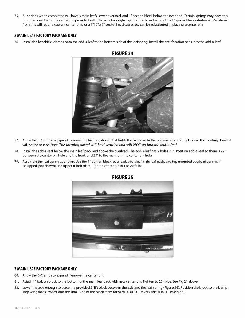
03420 2 Upper 4-Link Arm
03421 2 Lower 4-Link Arm
985 1 Bolt Pack - 4-link Arm Hardware2 M18-2.5 Prevailing Torque Nut - Clear Zinc
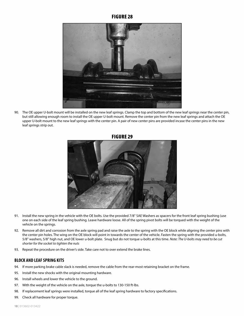
16 3/4 SAE Thru Hard Flat Washer - Clear Zinc
2 M18-2.5 x 150 Bolt - Class 10.9 - Clear Zinc
6 3/4"-10 x 5" Bolt - Grade 8 - Clear Zinc
6 3/4"-10 Prevailing Torque Nut - Clear Zinc
B1198 1 Bag Kit - Upper Arm
60107 2 90 degree grease fitting
7 2 1.0 x 0.120 x 3.25 DOM Sleeve
3527BK 4 Bushing
B1199 1 Bag Kit - Lower Arm
60107 2 90 degree grease fitting
7 2 1.0 x 0.120 x 3.25 DOM Sleeve
3527BK 4 Bushing
03422 4 Cam Lock Plate
BDS013516 or BDS013517 4" Rear Box Kit
Part # Qty Description
03410 1 5" Tapered Superduty Block (DRV)
03411 1 5" Tapered Superduty Block (PASS)
583181900S 4 5/8 x 3-1/8 x 19 Semi-Round U-bolt (013516)
583181600SB 4 5/8 x 3-1/8 x 16 Semi-Round U-bolt (013517)
B218 1 Bag Kit
W58SB 8 5/8" Washer
N58FHB 8 5/8" High Nut
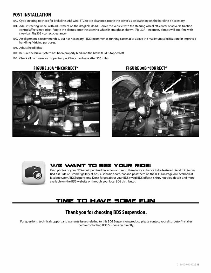
6" Rear Replacement Leaf Spring Box Kit
Part # Qty Description
583181400SB 4 5/8 x 3-1/8 x 14 Semi-Round U-Bolt
W78SB 4 7/8 washer
W58SB 8 5/8 washer
N58FHB 8 5/8 high nut
760400FCP 2 7/16 x 4 Pin w/Nut (CB716400)

4 | 013602-013422
FRONT INSTALLATION1. Park the vehicle on a clean, flat surface and block the rear wheels
for safety.
2. Disconnect the front track bar from the frame mount. Retain hardware.
Large Pitman Arm Puller
Small Pitman Arm Puller
30mm (1-3/16") Socket
46mm (1-13/16") Socket
Large Torque Wrench, ability to torque to 405 ft-lbs.
CV Boot Clamp Pliers
TROUBLESHOOTING INFORMATION FOR YOUR VEHICLE1. Ford recommends replacement of the pitman arm nut after each time it has been removed.
2. Use a small pitman arm puller to remove the drag link joint and steering stabilizer taper.
3. Larger tires on stock wheels are not recommended due to brakeline clearance required. Use recommended specifications listed in tire and wheel fitment section.
4. The factory front track bar bolt requires 405 ft-lbs of torque to be installed properly. Be sure you have the means of removing and installing this hardware properly. It is possible to install the hardware and torque to a more modest range (200 ft-lbs or so) and take the vehicle to a shop with the means to torque the hardware properly immediately after the installation is complete.
5. As a result of the location of the long radius arm suspension, support locations are limited. Use your best judgment while supporting the vehicle with sufficient strength stands at appropriate locations. The radius arms will need to move freely during this installation. Recommended to lift the front of the vehicle from the front body mount (An extension may be needed).
6. If replacement leaf springs are install the fuel tank will need to be dropped/ shifted towards the passenger's side of the vehicle. For ease of movement it is recommended to have the fuel tank low on fuel to reduce the weight when moving it.
7. Ensure the proper rear box kit is ordered for either a 2 or 3 leaf factory main pack. See example below of a 2 leaf main pack.
BDS013607 6" Rear Box Kit
Part # Qty Description
03410 1 5" Tapered Superduty Block (DRV)
03411 1 5" Tapered Superduty Block (PASS)
583181900SB 4 5/8 x 3-1/8 x 19 Semi-Round U-bolt
01015B 2 1" x 3" Bolt on Block
B1195 1 Bag Kit
760600FCP 2 7/16" x 6" Center Pin
W58SB 8 5/8" Washer
N58FHB 8 5/8" High Nut
BDS013219 6" Rear Box Kit (2-Leaf Main Pack Only)
Part # Qty Description
113219R 2 Add-a-leaf
B1196 1 Bag Kit
105 4 Clamp Sleeve
604 1 Bolt Pack - Clamps
01016 4 Clamp Bracket
1360017 4 Round Anti-Friction Pad
013602-013422 | 5
FIGURE 1
3. Raise the front of the vehicle and support under the frame rails with jack stands.
As a result of the location of the long radius arm suspension, support locations are limited. Use your best judgment while supporting the vehicle with sufficient strength stands at appropriate locations. The radius arms will need to move freely during this installation.
4. Remove the front wheels.
5. Support the front axle with a hydraulic jack.
6. Disconnect the front brake line brackets from the axle (Fig 2). Retain hardware.
FIGURE 2
7. Remove the bolts attaching the front brake lines brackets to the frame and save the hardware (Fig. 3). Attempt to not bend the brake lines as much as possbile. Remove the ABS line from the brake line bracket.

6 | 013602-013422
FIGURE 3
8. Free the hub vacuum lines from the axle/ radius arm to allow for adequate droop (Fig. 4A & B).
FIGURE 4A FIGURE 4B
9. Disconnect the upper sway bar end links from the sway bar. Push the sway bar up out of the way. Retain hardware.
10. Remove the lower OE shock hardware at this time (leave upper attached). Retain lower mounting hardware.
11. Lower the axle until the OE coil springs are free and remove the springs from the vehicle. Retain the upper spring isolator for use with the new springs. Once coils are removed, reattach the axle to the shocks.
Do not over extend the brake lines. Once the coil springs are removed, hook the front shocks back up by reinstalling the bolt, do not install the nut. This is a safety measure to hold the axle in place while the replacement radius arms are installed.
STEERING12. Disconnect the OE steering stabilizer from the frame mount. The factory frame mount can be removed or remain on the frame. Disconnect
the stabilizer from the factory drag link.
It is easiest to get the taper to break free from the drag link by using a small pitman arm puller. Stock stabilizer will not be reused.
13. Disconnect the (5) bolts mounting the OE track bar bracket to the frame (Fig. 5). Remove bracket and retain hardware.

013602-013422 | 7
FIGURE 5
14. Disconnect the steering drag link from the pitman arm. Remove the cotter pin and castellated nut cap. Remove the nut and thread back on by hand a couple turns. Strike the end of the pitman arm near the drag link end to dislodge the taper from the pitman arm (Fig. 6). Remove the nut and the drag link from the pitman arm. Retain hardware.
FIGURE 6
The same small pitman arm puller works well.
15. Remove the pitman arm nut. Note the indexing of the pitman arm in relation to the steering sector shaft and remove the pitman arm from the steering box using the appropriate puller.
16. Remove all of the dri-lock compound on the threads of the pitman arm nut and steering sector shafts. This is important to ensure that the new thread lock compound will adhere properly.
17. Apply a bead of the supplied thread lock all the way around the threads of the pitman arm nut.
18. Install the new pitman arm (indexed the same as the OE) and fasten with the pitman arm nut. Torque the nut to 350 ft-lbs.
19. Install the new track bar bracket (03412) using the stock mounting hardware as it was removed. Torque all (5) mounting bolts to 129 ft-lbs. It may be necessary to form the stock hard line slightly to clear the new track bar bracket. Do not install track bar at this time, it will be installed once the vehicle is on the ground.

8 | 013602-013422
FIGURE 7
BUMP STOP MODIFICATION20. Pull the OE front bump stops free from the bump stop cups and remove the bolt mounting the cup to the frame.
FIGURE 8
21. Position the cup on the provided bump stop extension. (01001) The alignment tab on the bump stop cup will fit in the second hole in the extension
22. Install a provided 8mm x 130mm bolt and 5/16” SAE washer through the cup extension and attach to the frame in the original hole. Use Loctite on the threads and torque to 20 ft-lbs (Fig 9 A & B).

013602-013422 | 9
FIGURE 9A FIGURE 9B
INDEXING RING INSTALLATION (REQUIRED ON 6" LIFT, OPTIONAL ON 4" LIFT)23. Refer to the provided instructions in the Indexing Ring Box Kit at this time.
FOUR LINK INSTALLATION:24. Working on one side of the vehicle at a time, loosen the four radius arm-to-axle mounting bolts but do not remove. Once again, ensure that the
front axle is well supported and the front drive shaft is disconnected. Failure to disconnect the front drivershaft will damage the front driveshaft CV joint at the transfer case output.
25. Starting with the driver’s side, remove the radius arm hardware and save hardware. Remove the radius arm from the vehicle. It may be necessary to remove one of the passenger’s side axle bolts to allow the axle to rotate to hook up the four link arm completely.
26. Support the new transfer case crossmember and remove the factory 12mm bolts on the driver's side used to support it.
Note: If the four link brackets are installed with the factory transfer case crossmember on a 4" kit, the transfer case crossmember will have to be removed to install the four link brackets. Support the transmission with a jack and block of wood to not damage the oil plan. Remove the (4) 12mm bolts and the center (2) nuts attaching the transfer case isolator.
27. Install the four link bracket to the factory radius arm bracket on the frame and around the transfer case crossmember mounts on the frame. The bracket will mount into the same hole as the factory radius arm. Insert a 3/4" bolt and washer from Bolt Pack 985 through the same hole in the radius arm bracket on the frame and through the four link bracket. Attach using the 3/4" nut and washer, leave hardware loose. Note: The factory hole for the radius arm on the frame may need to be clearanced to fit the 3/4" hardware.
FIGURE 10
28. Install the provided 12mm x 150mm bolts and washer from Bolt Pack 986 through the four link bracket, frame mounts, and the new crossmember running the bolts back to front. Attach using the provided 12mm prevailing torque nut and washer to the 12mm bolt. Leave all hardware loose (Fig. 11 A & B).
Note: If the four link brackets are installed with the factory transfer case crossmember on a 4" kit, install the factory crossmember along with the (4) new 12mm hardware.

10 | 013602-013422
FIGURE 11A FIGURE 11B
29. Drill a 9/16" hole in the frame through the hole in the side of the four link bracket. Insert the 9/16" x 1-1/2" bolt and washer from Bolt Pack 986 through the hole and attach using the provided 9/16" nut tab. Leave hardware loose.
FIGURE 12A FIGURE 12B
30. Lightly grease and install the provided bushings (3527) and sleeves (7) in the four new control arms.
31. Install the provided 90° grease fittings in the threaded holes at the bushing end of the control arms. When installed the fittings should point toward the body of the control arm.
32. Using a 3/4" x 5" bolt and hardware from Bolt Pack 985, install the assembled upper control arm (shorter of the two arms) into the front hole on the factory radius arm bracket (Fig. 13). Install the arm so that the grease fitting is down. Note: The factory hole for the radius arm on the frame may need to be clearanced to fit the 3/4" hardware. Attach the upper control arm to the axle using a factory 18mm bolt along with a factory 18mm nut. Leave hardware loose.
Note: The upper mount on the driver's side factory radius arm will have a captive nut. Use one of the left-over 18mm lower factory nuts for the upper bolt.
FIGURE 13
33. Using a 3/4" x 5" bolt and hardware from Bolt Pack 985, install the lower control arm into the lower hole on the four link bracket. Install the arm so that the grease fitting is up (Fig 14A). Attach the lower control arm to the axle using the provided 18mm x 150mm bolt, 3/4" SAE

013602-013422 | 11
washer, 18mm prevailing torque nut and cam plates. Index the cam plates so they are facing towards the rear of the vehicle in the cam slot on the lower control arm. Leave hardware loose (Fig 14B).
FIGURE 14A FIGURE 14B
34. Tighten the hardware for only the four link bracket (do not tighten the control arms at this time) in the following order: 12mm hardware to 50 ft-lbs, 9/16" hardware to 90 ft-lbs, 3/4" hardware to 150 ft-lbs. The control arm bolts at the frame and axle will be tightened when the vehicle is on the ground.
35. Repeat the frame bracket and control arm installation procedure on the passenger’s side of the vehicle.
Note: If the nuts for the center mounted transfer case isolator are still disconnected from the transfer case crossmember, reattach them now and torque to factory specifications.
COIL SPRING INSTALLATION (COILOVER INSTALLATION SEE SEPARATE INSTRUCTION SHEET)36. Remove the front shocks from the vehicle completely at this time.
37. Lower the axle enough to allow the coils to be installed. Do not over extend the brake lines. Check ABS, brake, and vacuum lines to ensure they are not overstretched.
38. Install new coils with factory isolators. Rotate the springs so that they seat in the bottom coil perch properly. Raise the axle to seat the coil springs into the correct mounts.
39. Grease and install sleeves and bushings into the shocks.
40. BDS (Silver / non-Fox) shocks will require the lower mount to be modified. The sharp, non-formed edge will need to be ground to match the formed profile. Grind this and coat with paint. (Fig 15a, 15b)
FIGURE 15A FIGURE 15B
41. Compress the coils slightly by using a hydraulic jack on the axle. Install new shocks with factory lower hardware and stem washers, bushings, and 1/2” fine thread nut on the upper mount. Tighten the upper mount until the bushings begin to swell. Tighten lower mount to 50 ft-lbs.
42. Reattach the factory brakeline brackets to the lower coil seat with factory hardware and Loctite at this time.

12 | 013602-013422
SWAY BAR43. Note the orientation of the front sway bar (top verses bottom). Disconnect the sway bar from the frame and remove from the vehicle.
Retain hardware.
44. Install the provided sway bar drop bracket to the original sway bar frame mounting locations with the original hardware. Mount the drop bracket with the open face toward the inside of the vehicle and the bracket offset toward the front. Leave hardware loose.
45. Attach the sway bar to the new drop brackets in the correct orientation with the 3/8” hardware from Bolt Pack #422. Torque the 3/8" and factory hardware to 30 ft-lbs (Fig 16). Center the bolts in the slots in the sway bar drop bracket. The position of the bracket may need to be adjusted for sway bar link to drag link clearance.
FIGURE 16
46. Install the sway bar link ends to the sway bar and secure with the OE hardware. Torque to 90 ft-lbs.
BRAKE LINE / ABS / VACUUM47. Reattach all vacuum lines. Use provided zip ties where needed. (4" Kit skip to step 54)
48. Install the provided brake line brackets with the factory hardware. The driver's side will be a straight drop (Fig. 17A) and the passenger's side will be angled back towards the rear of the vehicle (Fig. 17B).
FIGURE 17A FIGURE 17B
49. Remove the clip holding the brake line to the factory bracket. Save the clip for later installation.
50. Warning: The next three steps must be performed quickly to ensure minimal brake fluid loss. Unthread the factory soft brake line from the hard brake line.
51. Remove the factory brake line bracket from the brake line. Discard the bracket it will not be reused.
52. Thread the provided U-brake line with the union first onto the factory hard brake line, followed by threading the U-brake line onto the factory soft brake line. Check to make sure all connections are tight and no brake fluid is leaking.

013602-013422 | 13
53. Attach the factory soft brake line to the brake line bracket on the frame with the clip removed in the previous step. The brake line should be facing down towards the axle.
Note: The factory soft brake line may need to be rotated so that it will line up with the notches on the new brake line bracket on the frame. Break free the U-brake line from the soft line and rotate as needed.
54. Make sure the brake lines are close to the frame in order to provide clearance to the tires, but are not rubbing on the frame. The brake line junctions can be loosened and turned to provide clearance where needed (Fig. 17C & D).
FIGURE 17C FIGURE 17D
55. Attach the ABS wire to the new brake line bracket. The rubber grommet may need to be slid up the ABS line, use silicone spray to help aid in moving the rubber grommet.
FIGURE 18
56. 4" Kit Only: Install the new brake line brackets, brackets are side specific. Brake lines will need to be reformed to reach the new mounting position. It may be necessary to slightly twist the brakeline fittings in relation to the hardline to get adequate clearance to the frame / wheel and tire. Attach the ABS wire to the driver’s side with 1/4” hardware with rubber coated cable clamp (Fig 19A, 19B)
FIGURE 19A FIGURE 19B

14 | 013602-013422
STEERING STABILIZER57. Reattach the steering drag link to the pitman arm. Torque nut to 148 ft-lbs. Install the original castellated nut cap and new 1/8" cotter pin.
58. Skip this step is a dual steering stabilizer will be used. Center the steering wheel. Extend the steering stabilizer 4-1/2” to 4-3/4” and attach to the frame end with stud pack in the stabilizer box kit. Attach stabilizer bracket to the drag link with the included u-bolts, washers, and nuts. Attach stabilizer to bracket with 3/8” hardware. Tighten 5/16” hardware to 30 ft-lbs, 3/8” to 35 ft-lbs, 7/16” Stud nut to 45 ft-lbs, and 1/2” stud nut to 65ft-lbs. (Fig 20 A & B)
FIGURE 20A FIGURE 20B
59. Properly bleed the brake system of air and top off the brake fluid reservoir with the proper type of fluid (see owners manual).
60. Remove the factory CV joint clamp at the front transfer case output on the drive shaft. Slide the end of the boot up approximately 1/4" and reclamp with new CV joint boot clamp. Use the CV Boot Clamp Pliers to compress the CV joint boot clamp to the front drive shaft (Fig 21).
61. Reattach the front driveshaft to the front differential with factory hardware. Tighten to 55 ft-lbs.
FIGURE 21
1/4"
62. Install the front wheels and lower the vehicle to the ground. Torque lug nuts to 165 ft-lbs.
63. Attach the track bar to the new bracket with the OE hardware. Turn the steering wheels to aid in aligning the track bar in the bracket. Install the provided cam washers between the alignment tabs on the bracket. Position the cam washers so that the hole is closer to the driver’s side for 4” kits. (Figure 22) The hole should be closer to the passenger's side for 6" kits. Torque hardware to 406 ft-lbs.
Due to variations in trucks, it may be necessary to rotate the cams 180 degrees to have the axle more centered.

013602-013422 | 15
FIGURE 22 - 4" OFFSET TOWARDS DRIVER'S SIDE
64. If an indexing ring was installed, follow these instructions for the transfer case skid plate installation. Install the transfer case skid plate drop bracket on the driver side using the factory hardware into the J-nut in the frame. The bracket should be slanted towards the rear of the vehicle. Attach the transfer case skid plate to the J-nuts in the frame on the passenger side using the factory hardware. Attach the transfer case skid plate to the drop bracket on the driver's side using the 3/8" hardware from Bolt Pack 987 in the Indexing Ring kit. Torque to 20 ft-lbs (Figure 23).
FIGURE 23
65. Bounce the front of the vehicle to settle the suspension. Torque all four link hardware to 220 ft-lbs.
66. Check all hardware for proper torque.
REAR INSTALLATION67. Block the front wheels for safety.
68. Raise the rear of the vehicle and support with jack stands under the frame rails just ahead of the spring hangers.
69. Remove the wheels.
70. Support the axle with a hydraulic jack.
71. Remove the OE shocks. Retain all mounting hardware.
BLOCK KIT ONLY72. Disconnect the passenger’s side spring u-bolts. Loosen the driver’s side to allow the axle to droop out.
73. Lower the axle and remove the factory lift block. It will not be reused.
Note: 4" Kits skip ahead to rear block installation.
74. Clamp the main leaf pack together with C-Clamps. Remove the center pin nut and center pin.
16 | 013602-013422
75. All springs when completed will have 3 main leafs, lower overload, and 1" bolt on block below the overload. Certain springs may have top mounted overloads, the center pin provided will only work for single top mounted overloads with a 1" spacer block inbetween. Variations from this will require custom center pins, or a 7/16" x 7" socket head cap screw can be substituted in place of a center pin.
2 MAIN LEAF FACTORY PACKAGE ONLY76. Install the hendricks clamps onto the add-a-leaf to the bottom side of the leafspring. Install the anti-frication pads into the add-a-leaf.
FIGURE 24
77. Allow the C-Clamps to expand. Remove the locating dowel that holds the overload to the bottom main spring. Discard the locating dowel it will not be reused. Note: The locating dowel will be discarded and will NOT go into the add-a-leaf.
78. Install the add-a-leaf below the main leaf pack and above the overload. The add-a-leaf has 2 holes in it. Position add-a-leaf so there is 22" between the center pin hole and the front, and 23" to the rear from the center pin hole.
79. Assemble the leaf spring as shown. Use the 1" bolt on block, overload, add-aleaf,main leaf pack, and top mounted overload springs if equipped (not shown),and upper u-bolt plate. Tighten center pin nut to 20 ft-lbs.
FIGURE 25
3 MAIN LEAF FACTORY PACKAGE ONLY80. Allow the C-Clamps to expand. Remove the center pin.
81. Attach 1" bolt on block to the bottom of the main leaf pack with new center pin. Tighten to 20 ft-lbs. See Fig 21 above.
82. Lower the axle enough to place the provided 5” lift block between the axle and the leaf spring (Figure 26). Position the block so the bump stop wing faces inward, and the small side of the block faces forward. (03410 - Drivers side, 03411 - Pass side)

013602-013422 | 17
FIGURE 26
83. Raise the axle to engage the block spring alignment pins. Fasten the entire assembly with the provided u-bolts, washers, and nuts. Snug but do not torque the u-bolts at this time.
FIGURE 27
84. Repeat block installation of the driver’s side. Take care not to over extend the brake lines.
6" REPLACEMENT REAR LEAF SPRING KIT ONLY85. Disconnect the passenger’s side u-bolts and lower the axle from the spring.
86. Retain OE block to be installed with new spring.
87. Loosen and remove the front spring-to-frame and rear shackle-to-frame bolts and remove the spring from the vehicle. Note: When installing the driver's side leaf spring the fuel tank may have to be shifted towards the passenger's side of the vehicle to remove the front spring-to-frame bolt. Support the fuel tank and loosen the bolts for the fuel tank hanger. Shift the fuel tank towards the passenger's side of the vehicle to remove the leaf spring bolt.
88. Remove the shackle from the OE spring and loosely install it on the new rear spring. Be sure that the shackle is oriented on the new spring identical to the old. The shackles mount of the longer end of the spring (opposite of the end marked with “FRT”).
89. Using a pair of clamps, clamp the top and bottom of the factory leaf next to the OE upper U-bolt mount. Remove the OE upper U-bolt mount from the center pin on the top of the OE leaf spring in order to be installed on the new spring. Reassemble the OE leaf spring with the OE center pin and remove the clamps (Figure 28).
18 | 013602-013422
FIGURE 28
90. The OE upper U-bolt mount will be installed on the new leaf springs. Clamp the top and bottom of the new leaf springs near the center pin, but still allowing enough room to install the OE upper U-bolt mount. Remove the center pin from the new leaf springs and attach the OE upper U-bolt mount to the new leaf springs with the center pin. A pair of new center pins are provided incase the center pins in the new leaf springs strip out.
FIGURE 29
91. Install the new spring in the vehicle with the OE bolts. Use the provided 7/8" SAE Washers as spacers for the front leaf spring bushing (use one on each side of the leaf spring bushing. Leave hardware loose. All of the spring pivot bolts will be torqued with the weight of the vehicle on the springs.
92. Remove all dirt and corrosion from the axle spring pad and raise the axle to the spring with the OE block while aligning the center pins with the center pin holes. The wing on the OE block will point in towards the center of the vehicle. Fasten the spring with the provided u-bolts, 5/8" washers, 5/8" high nut, and OE lower u-bolt plate. Snug but do not torque u-bolts at this time. Note: The U-bolts may need to be cut shorter for the socket to tighten the nuts
93. Repeat the procedure on the driver’s side. Take care not to over extend the brake lines.
BLOCK AND LEAF SPRING KITS94. If more parking brake cable slack is needed, remove the cable from the rear-most retaining bracket on the frame.
95. Install the new shocks with the original mounting hardware.
96. Install wheels and lower the vehicle to the ground.
97. With the weight of the vehicle on the axle, torque the u-bolts to 130-150 ft-lbs.
98. If replacement leaf springs were installed, torque all of the leaf spring hardware to factory specifications.
99. Check all hardware for proper torque.
013602-013422 | 19
POST INSTALLATION100. Cycle steering to check for brakeline, ABS wire, ETC to tire clearance, rotate the driver's side brakeline on the hardline if necessary.
101. Adjust steering wheel with adjustment on the draglink, do NOT drive the vehicle with the steering wheel off-center or adverse traction control affects may arise. Rotate the clamps once the steering wheel is straight as shown. (Fig 30A - incorrect, clamps will interfere with sway bar, Fig 30B - correct clearance)
102. An alignment is recommended, but not necessary. BDS recommends running caster at or above the maximum specification for improved handling / driving purposes.
103. Adjust headlights
104. Be sure the brake system has been properly bled and the brake fluid is topped off.
105. Check all hardware for proper torque. Check hardware after 500 miles.
FIGURE 30A *INCORRECT* FIGURE 30B *CORRECT*
Thank you for choosing BDS Suspension.For questions, technical support and warranty issues relating to this BDS Suspension product, please contact your distributor/installer
before contacting BDS Suspension directly.