Embed Size (px)
Citation preview
Amendment No. 2 (12/2018) To
AIS-145 Additional Safety features for Category M & N Vehicles
1. Page No. 1 of 26 Clause 5.2.
Substitute following text for existing text:
5.2 Driver and co-driver safety belt reminder provided in category M1, shall meet requirements given at Annexure 3. Vehicles complying AIS-145 safety belt reminder installation requirement are deemed to comply relevant requirements of IS 16694:2018.
2. Page No. 11 of 26 Annexure 5, Clause 2.1.
Substitute following text for existing text:
2.1 Vehicles of category M1 with total permissible mass not exceeding 2.5 tones shall be equipped with appropriately designed driver airbag and shall comply with the performance requirements of AIS-098 or requirements as per para 5.2 and 5.3 of AIS-096 or requirements as per para 6 and 8 of IS-11939, as applicable.
Vehicles of category M1 with total permissible mass exceeding 2.5 tones shall be equipped with driver airbag. The verification of compliance as per para. 5.2 and 5.3 of AIS-096 shall be done with steering airbag equipped.
For vehicles complying the requirements of AIS-098 with Driver Airbag, testing as per para. 5.2 and 5.3 of AIS-096 with driver airbag need not be conducted, provided requirements as per para 5.2 and 5.3 of AIS-096 are already complied without Airbag.
PRINTED BY THE AUTOMOTIVE RESEARCH ASSOCIATION OF INDIA
P.B. NO. 832, PUNE 411 004
ON BEHALF OF AUTOMOTIVE INDUSTRY STANDARDS COMMITTEE
UNDER CENTRAL MOTOR VEHICLE RULES – TECHNICAL STANDING COMMITTEE
SET-UP BY MINISTRY OF ROAD TRANSPORT & HIGHWAYS
(DEPARTMENT OF ROAD TRANSPORT & HIGHWAYS) GOVERNMENT OF INDIA
5th December 2018
1/1
AMENDMENT NO. 1 (08/2018)
To
AIS-145
Additional Safety features for Category M & N Vehicles
1. Page 1/26, clause 1.1
Substitute following text for existing text: “1.1 This standard specifies the requirements for additional safety features for M & N category vehicles that are aimed to further enhance vehicular and road safety.
The requirements of this standard are applicable to M1 category vehicles in respect of the following:
(i) Speed alert system to alert driver in case of over speeds; (ii) Driver and co-driver safety belt reminder; (iii) Manual override for central locking system; (iv) Driver Airbag The requirements of vehicle reverse parking alert system of this standard shall be applicable to all M and N category vehicles, as defined in AIS-053.
Child safety lock system shall not be permitted for M1 category Transport vehicles.”
2. Page 1/26
Add following new clause 3.1 after clause 3.
“3.1 Child Safety Lock System” means a locking device which is able to be engaged
and released independently of other locking devices and which, when engaged, prevents operation of interior door handle or other release device.
3. Page 2/26
Add following new clause 5.7 after clause 5.6. 5.7 Incomplete vehicles of M, N category, where the cabin build level of the
incomplete vehicle prevents the fitment of the reverse parking assist system, the vehicle manufacturer shall provide these items as a kit along with the vehicle and accompanied with suitable guidelines to facilitate the body builder in installing the system as per type approval. While carrying out component testing appropriate mock-up of vehicle rear or test bench simulating sensor installation condition shall be used.
4. Page 2/26
Add following new clause 5.8 after clause 5.7. “5.8 In case of M1 category Transport vehicles “Child Safety Lock System” is not
permitted.
Note: Since transport application is not known at the time of vehicle production, vehicle manufacturer may choose to implement the above requirement at manufacturing stage or dealership stage.”
5. Page 19/26, Annexure 7
Add following new clause 2.7 after clause 2.6: “2.7 Incomplete vehicles shall also be equipped with reverse park assist system.
Where the cabin build level of the incomplete vehicles prevents the fitment of the reverse park assist system, the vehicle manufacturer shall provide these items as a type approved kit along with the vehicle and accompanied with suitable guidelines to facilitate the body builder in installing the items.”
PRINTED BY
THE AUTOMOTIVE RESEARCH ASSOCIATION OF INDIA
P.B. NO. 832, PUNE 411 004
ON BEHALF OF
AUTOMOTIVE INDUSTRY STANDARDS COMMITTEE
UNDER
CENTRAL MOTOR VEHICLE RULES – TECHNICAL STANDING COMMITTEE
SET-UP BY
MINISTRY OF ROAD TRANSPORT & HIGHWAYS
(DEPARTMENT OF ROAD TRANSPORT & HIGHWAYS)
GOVERNMENT OF INDIA
August 1, 2018
AIS-145
I
AUTOMOTIVE INDUSTRY STANDARD
Additional Safety features for Category M & N Vehicles
PRINTED BY THE AUTOMOTIVE RESEARCH ASSOCIATION OF INDIA
P.B. NO. 832, PUNE 411 004
ON BEHALF OF AUTOMOTIVE INDUSTRY STANDARDS COMMITTEE
UNDER
CENTRAL MOTOR VEHICLE RULES – TECHNICAL STANDING COMMITTEE
SET-UP BY MINISTRY OF ROAD TRANSPORT and HIGHWAYS
(DEPARTMENT OF ROAD TRANSPORT and HIGHWAYS) GOVERNMENT OF INDIA
May 2018
AIS-145
II
Status chart of the Standard to be used by the purchaser for updating the record
Sr. No.
Corrigenda.
Amend-ment
Revision Date Remark Misc.
General remarks:
AIS-145
III
INTRODUCTION
The Government of India felt the need for a permanent agency to expedite the publication of standards and development of test facilities in parallel when the work on the preparation of the standards is going on, as the development of improved safety critical parts can be undertaken only after the publication of the standard and commissioning of test facilities. To this end, the erstwhile Ministry of Surface Transport (MoST) has constituted a permanent Automotive Industry Standards Committee (AISC) vide order No. RT-11028/11/97-MVL dated September 15, 1997. The standards prepared by AISC will be approved by the permanent CMVR Technical Standing Committee (CTSC). After approval, the Automotive Research Association of India, (ARAI), Pune, being the secretariat of the AIS Committee, has published this standard. Ministry of Road Transport took initiative to further increase vehicular safety with the aim to reduce causes of accidents. Following was the focus while formulation of this standard:
1. Enhancement in use of safety belts to improve safety 2. Accidents caused due to over speeding of vehicles. 3. Ease of occupant exit in case of electric power failure in a centrally locked
vehicle 4. Reduce possibilities of accidents (child over run) while parking in reverse
gear. 5. Driver airbag mandate as additional passive safety measure.
This standard specifies requirements of special features, which are in addition to present mandatory requirements to mitigate above causes. Reverse Park Alert Systems (RPAS) which uses object-detection devices (sensors) or camera based displays in order to provide the driver with information about obstacles in specified zone while reversing the vehicle The test objects in this standard are defined based on systems using ultrasonic sensors and electro-magnetic sensors which reflect the most commonly used technology. For other sensing technologies possibly coming up in the future, these test objects shall be checked and changed if required. The AISC panel responsible for formulation of this standard is given in Annex 8.
The Automotive Industry Standards Committee (AISC) responsible for approval of this standard is given in Annex 9.
AIS-145
1/26
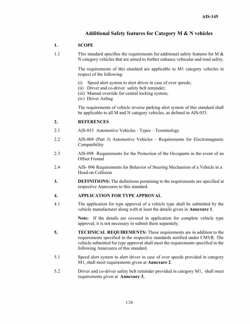
Additional Safety features for Category M & N vehicles
1. SCOPE
1.1 This standard specifies the requirements for additional safety features for M & N category vehicles that are aimed to further enhance vehicular and road safety. The requirements of this standard are applicable to M1 category vehicles in respect of the following:
(i) Speed alert system to alert driver in case of over speeds; (ii) Driver and co-driver safety belt reminder; (iii) Manual override for central locking system; (iv) Driver Airbag
The requirements of vehicle reverse parking alert system of this standard shall be applicable to all M and N category vehicles, as defined in AIS-053.
2. REFERENCES
2.1 AIS-053 Automotive Vehicles - Types – Terminology
2.2 AIS-004 (Part 3) Automotive Vehicles – Requirements for Electromagnetic Compatibility
2.3 AIS-098 Requirements for the Protection of the Occupants in the event of an Offset Frontal
2.4 AIS- 096 Requirements for Behavior of Steering Mechanism of a Vehicle in a Head-on Collision
3.
DEFINITIONS: The definitions pertaining to the requirements are specified at respective Annexures to this standard.
4. APPLICATION FOR TYPE APPROVAL
4.1 The application for type approval of a vehicle type shall be submitted by the vehicle manufacturer along with at least the details given in Annexure 1.
Note: If the details are covered in application for complete vehicle type approval, it is not necessary to submit them separately.
5. TECHNICAL REQUIREMENTS: These requirements are in addition to the requirements specified in the respective standards notified under CMVR. The vehicle submitted for type approval shall meet the requirements specified in the following Annexures of this standard.
5.1 Speed alert system to alert driver in case of over speeds provided in category M1, shall meet requirements given at Annexure 2.
5.2 Driver and co-driver safety belt reminder provided in category M1, shall meet requirements given at Annexure 3;
AIS-145
2/26
5.3 Manual override for central locking system for category M1 shall meet requirements given at Annexure 4.
5.4 Driver airbag provided in category M1 shall meet requirements given at Annexure 5.
5.5 Vehicle reverse parking alert shall meet requirements of Annexure 6 for vehicle of M1 category and M2 category derived from M1.
5.6 Vehicle Reverse Parking Alert shall meet requirements of Annexure 7 for vehicles other than M1 category.
All vehicles other than M1 equipped with vehicle reverse parking alert shall comply with the requirements of Annexure 7 of this standard. To address the diversity of vehicle heights and rear end configuration, it shall be permissible for vehicles of category other than M1 to comply with the requirements of Annexure 6 as an alternative. Tractors including Puller Tractors of N category shall be exempted from the requirements of both Annexures 6 & 7.
6 EXTENSION OF TYPE APPROVAL
6.1 Every modification pertaining to the information, even if the changes are not technical in nature declared in accordance with 4.1 shall be intimated by the manufacturer to the testing agency.
If the changes are in parameters not related to the provisions, no further action need be taken.
If the changes are in parameters related to the provisions, the Testing Agency, which has issued the certificate of compliance, shall then consider, whether,
6.1.1 the device with the changed specifications still complies with provisions, or
6.1.2 Any further verification is required to establish compliance.
6.2 In case of 6.1.2, tests for only those parameters which are affected by the modifications need be carried out
6.3 In case of fulfilment of criterion of para 6.1.1 or after results of further verification as per para of 6.1.2 are satisfactory, the approval of compliance shall be extended for the changes carried out.
AIS-145
3/26
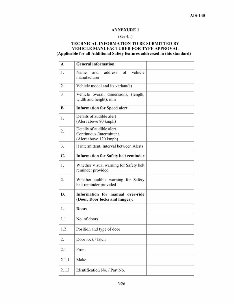
ANNEXURE 1
(See 4.1)
TECHNICAL INFORMATION TO BE SUBMITTED BY VEHICLE MANUFACTURER FOR TYPE APPROVAL
(Applicable for all Additional Safety features addressed in this standard)
A General information
1. Name and address of vehicle manufacturer
2 Vehicle model and its variant(s)
3 Vehicle overall dimensions, (length, width and height), mm
B Information for Speed alert
1. Details of audible alert (Alert above 80 kmph)
2. Details of audible alert Continuous /intermittent. (Alert above 120 kmph)
3. if intermittent, Interval between Alerts
C. Information for Safety belt reminder
1. Whether Visual warning for Safety belt reminder provided
2. Whether audible warning for Safety belt reminder provided
D. Information for manual over-ride (Door, Door locks and hinges):
1. Doors
1.1 No. of doors
1.2 Position and type of door
2. Door lock / latch
2.1 Front
2.1.1 Make
2.1.2 Identification No. / Part No.
AIS-145
4/26
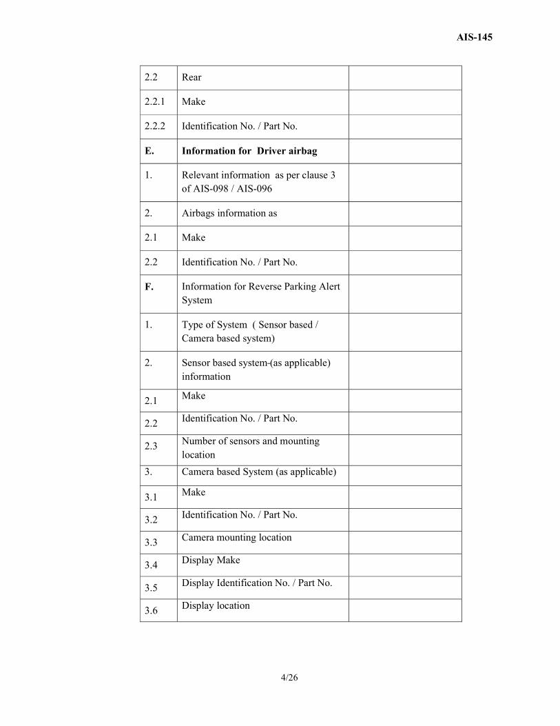
2.2 Rear
2.2.1 Make
2.2.2 Identification No. / Part No.
E. Information for Driver airbag
1. Relevant information as per clause 3 of AIS-098 / AIS-096
2. Airbags information as
2.1 Make
2.2 Identification No. / Part No.
F. Information for Reverse Parking Alert System
1. Type of System ( Sensor based / Camera based system)
2. Sensor based system (as applicable) information
2.1 Make
2.2 Identification No. / Part No.
2.3 Number of sensors and mounting location
3. Camera based System (as applicable)
3.1 Make
3.2 Identification No. / Part No.
3.3 Camera mounting location
3.4 Display Make
3.5 Display Identification No. / Part No.
3.6 Display location
AIS-145
5/26
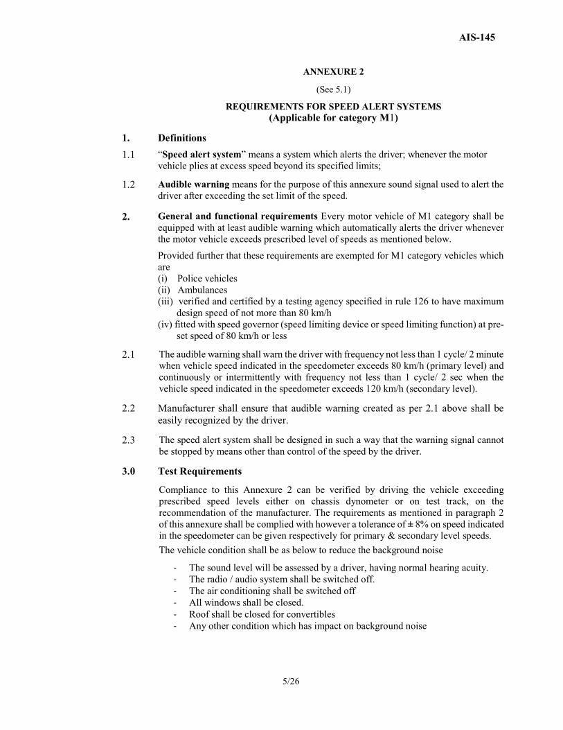
ANNEXURE 2
(See 5.1)
REQUIREMENTS FOR SPEED ALERT SYSTEMS (Applicable for category M1)
1.
Definitions
1.1 “Speed alert system” means a system which alerts the driver; whenever the motor vehicle plies at excess speed beyond its specified limits;
1.2 Audible warning means for the purpose of this annexure sound signal used to alert the driver after exceeding the set limit of the speed.
2. General and functional requirements Every motor vehicle of M1 category shall be equipped with at least audible warning which automatically alerts the driver whenever the motor vehicle exceeds prescribed level of speeds as mentioned below.
Provided further that these requirements are exempted for M1 category vehicles which are (i) Police vehicles (ii) Ambulances (iii) verified and certified by a testing agency specified in rule 126 to have maximum
design speed of not more than 80 km/h (iv) fitted with speed governor (speed limiting device or speed limiting function) at pre-
set speed of 80 km/h or less
2.1 The audible warning shall warn the driver with frequency not less than 1 cycle/ 2 minute when vehicle speed indicated in the speedometer exceeds 80 km/h (primary level) and continuously or intermittently with frequency not less than 1 cycle/ 2 sec when the vehicle speed indicated in the speedometer exceeds 120 km/h (secondary level).
2.2 Manufacturer shall ensure that audible warning created as per 2.1 above shall be easily recognized by the driver.
2.3 The speed alert system shall be designed in such a way that the warning signal cannot be stopped by means other than control of the speed by the driver.
3.0 Test Requirements
Compliance to this Annexure 2 can be verified by driving the vehicle exceeding prescribed speed levels either on chassis dynometer or on test track, on the recommendation of the manufacturer. The requirements as mentioned in paragraph 2 of this annexure shall be complied with however a tolerance of ± 8% on speed indicated in the speedometer can be given respectively for primary & secondary level speeds.
The vehicle condition shall be as below to reduce the background noise
- The sound level will be assessed by a driver, having normal hearing acuity. - The radio / audio system shall be switched off. - The air conditioning shall be switched off - All windows shall be closed. - Roof shall be closed for convertibles - Any other condition which has impact on background noise
AIS-145
6/26
ANNEXURE 3
(See 5.2)
SAFETY-BELT REMINDER REQUIREMENTS (Applicable for category M1)
1.
Definitions
1.1 “Safety-belt reminder” means a system dedicated to alert the driver when driver and /or co-driver does not use the safety-belt. The system is constituted by a detection of an unfastened safety-belt and by a driver's alert which is a first level warning and a second level warning.
1.1.1 “Visual Warning” means a warning by visual signal (lighting, blinking or visual display of symbol or message).
1.1.2 “Audible Warning” means a warning by sound signal.
1.1.3 “First Level Warning” means a visual warning activated when the ignition switch is engaged (engine running or not) and the driver's and/or co-driver’s safety-belt is not fastened. An audible warning can be added as an option.
1.1.4 “Second Level Warning” means a visual and audible warning activated when a driver operates a vehicle without fastening of driver and/or co-driver safety-belt.
1.1.5 “Safety-Belt is not fastened” means, at the option of the manufacturer, either the driver and /or co-driver safety-belt buckle is not engaged or the webbing length pulled out of the retractor is 100 mm or less.
1.1.6 “Vehicle is in Normal Operation” means that vehicle is in forward motion at the speed greater than 10 km/h.
1.1.7 "Co-Driver" means the person occupying the Front outboard seating position, other than the driver seat.
2. Requirements concerning the Safety-Belt Reminder
2.1 Safety-Belt Reminder Equipment
2.1.1 Vehicle manufacturer shall equip the driver and co-driver seating position of M1 category of vehicles with a safety-belt reminder system, the vehicle manufacturer shall provide following:
a) First level Warning b) Second level Warning:
The safety-belt reminder system shall satisfy the requirements of 2.1.2
AIS-145
7/26
2.1.1.1 The deactivation of the safety-belt reminder may be allowed, provided that such deactivation satisfies to the requirements of 2.1.2.6.
2.1.2 Safety-Belt Reminder
2.1.2.1 General Requirements
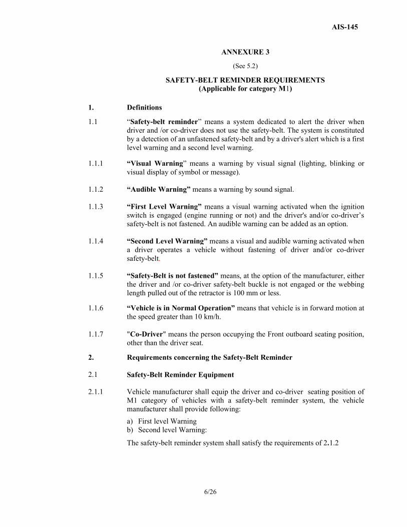
2.1.2.1.1 Visual warning shall be so located as to be readily visible and recognisable in the daylight by the driver and distinguishable from other alerts. Where the visual signal warning employs the colour red, it shall use a symbol as shown in Fig.2 below.
FIG. 2 2.1.2.1.2 Visual warning shall be by continuous or intermittent signal.
2.1.2.1.3 Audible warning shall be by continuous or intermittent sound signal or by vocal
information. Where vocal information is employed, the manufacturer shall ensure that the alert uses the language either English or Hindi. This audible warning may be constituted by more than one step.
2.1.2.1.4 Audible warning shall be easily recognized by the driver.
2.1.2.2 First level warning shall be at least a visual warning activated for 4 seconds or longer when the driver and/or co-driver safety-belt is not fastened and the ignition switch is engaged.
2.1.2.2.1 The first level warning may be discontinued when (i) None of the safety-belts which triggered the warning are unfastened, or (ii) The seat or seats which triggered the warning are no longer occupied.
2.1.2.3 The activation of the first level warning shall be tested according to the test procedure defined in 3.1
2.1.2.4 Second level warning shall be a visual and audible signal activated for 30 seconds or longer except for cases in which the warning stops for over 3 seconds when the safety-belt is not fastened, when the vehicle is in normal operation and when at least one of the following conditions (or any combination of these conditions), is fulfilled:
a) Distance driven greater than the distance threshold. The threshold shall not exceed 500 m. The distance the vehicle is not in normal operation shall be excluded.
b) Speed greater than the speed threshold. The threshold shall not exceed 25 km/h.
or
AIS-145
8/26
c) Duration time (engine running) greater than the duration time threshold. The threshold shall not exceed 60 seconds. The first level warning duration time and the duration time the vehicle is not in normal operation shall be excluded.
2.1.2.4.1 The thresholds to trigger safety belt reminder listed in paragraphs 2.1.2.4 (a) to (c), may be reset when:
(i) Any of the doors have been opened while the vehicle is not in normal operation or
(ii) The seat or seats which triggered the warning are no longer occupied.
2.1.2.4.2 The second level warning may be discontinued when
(i) None of the safety-belts which triggered the warning are unfastened, (ii) The vehicle ceases to be in normal operation, or (iii) The seat or seats which triggered the warning are no longer occupied.
2.1.2.5 The activation of the second level warning shall be tested according to the test procedure defined in 3.2.
2.1.2.6 The safety-belt reminder may be designed to allow deactivation.
2.1.2.6.1 In the case a short term deactivation is provided, it shall be more difficult to deactivate the safety-belt reminder than buckling the safety-belt on and off. When the ignition is switched off for more than 30 minutes and switched on again, a short-term deactivated safety-belt reminder must reactivate.
2.1.2.6.2 In the case that a facility for a long term deactivation is provided, it shall require a sequence of operations to deactivate, that are detailed only in the manufacturer's technical manual and/or which requires the use of tools (mechanical, electrical, digital, etc.) that are not provided with the vehicle.
3.0 Safety-belt reminder tests
3.1 The first level warning shall be tested according to the following conditions:
a) Safety-belt is not fastened; b) Engine is stopped or idling and the vehicle is not in forward or reverse
motion; c) Transmission is in neutral position; d) Ignition switch is engaged.
3.2 The second level warning shall be tested according to the following conditions:
a) Safety-belt is not fastened; b) Test vehicle driven with one or any combination of the conditions of
described in 3.2.1 to 3.2.3 at the manufacturer's choice.
3.2.1 Accelerate the test vehicle to 25 –0/+10 km/h from a halt and continue on the same speed.
3.2.2 The test vehicle is driven forward at least 500 m from a halt position.
3.2.3 The vehicle is tested when the vehicle is in normal operation for at least 60 seconds.

AIS-145
9/26
3.3 A system that the first level warning stops after a certain period of time, the second level warning shall be tested according to 3.2 after the first level warning has been deactivated. A system that the first level warning does not stop after a certain period of time, the second level warning shall be tested according to 3.2 while the first level warning is activated.
AIS-145
10/26
ANNEXURE 4 (See 5.3)
REQUIREMENTS FOR MANUAL OVERRIDE FOR CENTRAL LOCKING SYSTEM
(Applicable for category M1)
1.
Definitions
1.1 “Manual over-ride” means the system that enables the motor vehicle occupant to open the door from inside using door release lever or control with or without electric power assistance to door locking system.
2. Requirements
2.1. Manual override system need to satisfy following functional requirement
2.2 In order to avoid non-opening of side doors after activation of central locking system, there shall be provision by way of manual over-ride or otherwise that enables the vehicle occupant to open the door from inside using door release lever / control regardless of with or without electric power assistance to door locking system. This requirement shall not be applicable when the child safety lock system of the door is engaged.
2.3 Functionality of manual override shall be checked with following procedure with vehicle in static condition.
1. Vehicle occupant shall activate central lock to lock all the doors, with child safety lock system of the door in disengaged mode.
2. Disconnect electrical supply either at system level (For example central locking, controller, etc.) or disconnect main battery supply by suitable means.
Occupant shall be able to open the door from inside using internal controls

AIS-145
11/26
ANNEXURE 5
(See 5.4)
REQUIREMENTS FOR DRIVER AIRBAG (Applicable for category M1)
1.
Definitions
1.1 "Airbag" means a device installed to supplement safety belts and restraint systems in power-driven vehicles, i.e. systems which, in the event of a severe impact affecting the vehicle, automatically deploy a flexible structure intended to limit, by compression of the gas contained within it, the gravity of the contacts of one or more parts of the body of an occupant of the vehicle with the interior of the passenger compartment.
2. Requirements
2.1. Vehicles of category M1 with total permissible mass not exceeding 2.5 tones shall be equipped with appropriately designed driver airbag and shall comply with the performance requirements of AIS-098. Vehicles of category M1 with total permissible mass exceeding 2.5 tones shall be equipped with driver airbag. The verification of compliance as per para. 5.2 and 5.3 of AIS-096 shall be done with steering airbag equipped. For vehicles complying the requirements of AIS-098 with Driver Airbag, testing as per para. 5.2 and 5.3 of AIS-096 with driver airbag need not be conducted, provided requirements as per para 5.2 and 5.3 of AIS-096 are already complied without Airbag.
AIS-145
12/26
ANNEXURE 6
(See 5.5) ,
REQUIREMENTS FOR VEHICLE REVERSE PARKING ALERT (Applicable for category M1, M2 derived from M1)
1. Definitions
1.1 “Vehicle reverse parking alert” means a systems that are designed to alert / display the driver about obstacles on rear side of vehicles during parking in reverse gear”
1.2 “Audible information and warning” means acoustical signal that is used to present information about relevant obstacles, to the driver
1.3 “Visual information and warning” means Optical signal which is used to present information about relevant obstacles to the driver
1.4 Monitoring range (M.R.)
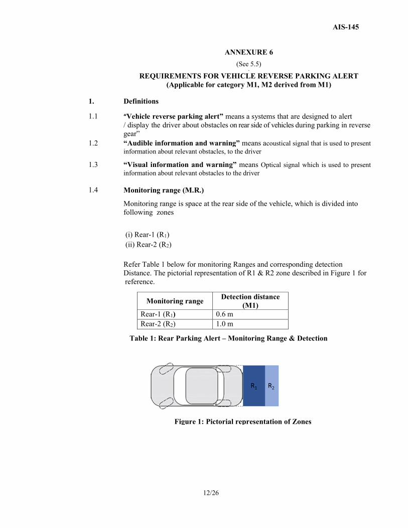
Monitoring range is space at the rear side of the vehicle, which is divided into following zones
(i) Rear-1 (R1) (ii) Rear-2 (R2) Refer Table 1 below for monitoring Ranges and corresponding detection Distance. The pictorial representation of R1 & R2 zone described in Figure 1 for reference.
Monitoring range Detection distance
(M1) Rear-1 (R1) 0.6 m Rear-2 (R2) 1.0 m
Figure 1: Pictorial representation of Zones
Table 1: Rear Parking Alert – Monitoring Range & Detection
AIS-145
13/26
1.5 Reversing detection system
System that gives an indication to the driver, when the reverse gear is selected, whether there are objects in the rear monitoring range.
1.6 Sensor
Component that detects objects in the monitoring range.
1.7 System activation Action of transitioning the system operation from a non-active mode to an active mode in which the system is monitoring the rear monitoring ranges, evaluating the objects detected and generating appropriate feedback to assist the driver.
1.8 Test object Object with a specific material, geometry and surface for testing the monitoring range as detailed in clause 3.
2.0 Functional and performance requirements
2.1 2.1.1
2.1.2 2.1.3
2.1.4 2.1.5 2.1.6
System activation and deactivation The system is activated/deactivated automatically according to the driving situation Activation criteria is Reverse gear selected .Deactivation criteria is gear other than reverse is selected. The system may have on / off switch or push button to override automatic (de) activation In order to reduce annoyance of the driver, the system may automatically switch off the audible signal temporarily after a certain time (duration can be defined by manufacturer). The system, however shall remain in active state. On vehicles with automatic transmission the system may be deactivated if the P (parking) gear position is selected. It may be allowed to deactivate the system while the parking brake is engaged.
2.2 Parking Alert information
2.2.1 The Rear parking alert system shall give an acoustic signal to warn the driver on the obstacles detected in the monitoring range in case of sensor based system.
The system may have optical warning as supplementary alert to warn the driver.
In case of camera based systems, obstacle within monitoring range shall be visible to driver. Additionally Vehicle manufacturer may provide acoustic warning or optical warning or both.
AIS-145
14/26
2.2.2 Duration of signaling
In general, signaling an obstacle shall be maintained as long as the obstacle is detected and shall cease when the obstacle is no longer detected or the system is deactivated.
Provided that provisions under clause 2.1 shall be permitted.
2.3 Monitoring Range coverage
Rear parking alert system shall meet the performance requirements described below. Vehicle shall be in normal condition during the verification.
2.3.1
2.3.2
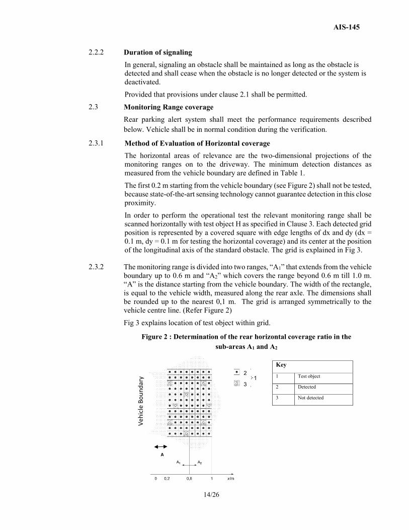
Method of Evaluation of Horizontal coverage
The horizontal areas of relevance are the two-dimensional projections of the monitoring ranges on to the driveway. The minimum detection distances as measured from the vehicle boundary are defined in Table 1.
The first 0.2 m starting from the vehicle boundary (see Figure 2) shall not be tested, because state-of-the-art sensing technology cannot guarantee detection in this close proximity.
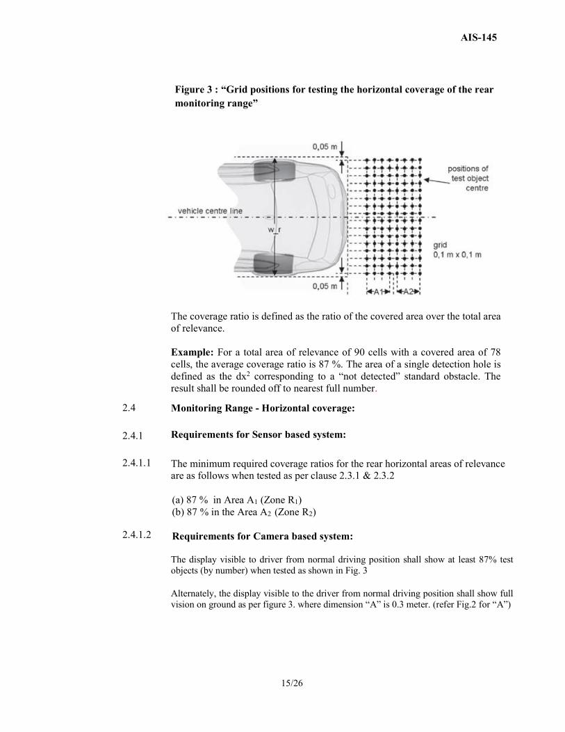
In order to perform the operational test the relevant monitoring range shall be scanned horizontally with test object H as specified in Clause 3. Each detected grid position is represented by a covered square with edge lengths of dx and dy (dx = 0.1 m, dy = 0.1 m for testing the horizontal coverage) and its center at the position of the longitudinal axis of the standard obstacle. The grid is explained in Fig 3.
The monitoring range is divided into two ranges, “A1” that extends from the vehicle boundary up to 0.6 m and “A2” which covers the range beyond 0.6 m till 1.0 m. “A” is the distance starting from the vehicle boundary. The width of the rectangle, is equal to the vehicle width, measured along the rear axle. The dimensions shall be rounded up to the nearest 0,1 m. The grid is arranged symmetrically to the vehicle centre line. (Refer Figure 2)
Fig 3 explains location of test object within grid.
Key
1 Test object
2 Detected
3 Not detected
Vehi
cle
Boun
dary
Figure 2 : Determination of the rear horizontal coverage ratio in the sub-areas A1 and A2
A
AIS-145
15/26
The coverage ratio is defined as the ratio of the covered area over the total area of relevance. Example: For a total area of relevance of 90 cells with a covered area of 78 cells, the average coverage ratio is 87 %. The area of a single detection hole is defined as the dx2 corresponding to a “not detected” standard obstacle. The result shall be rounded off to nearest full number.
2.4
2.4.1
2.4.1.1 2.4.1.2
Monitoring Range - Horizontal coverage:
Requirements for Sensor based system:
The minimum required coverage ratios for the rear horizontal areas of relevance are as follows when tested as per clause 2.3.1 & 2.3.2
(a) 87 % in Area A1 (Zone R1) (b) 87 % in the Area A2 (Zone R2) Requirements for Camera based system: The display visible to driver from normal driving position shall show at least 87% test objects (by number) when tested as shown in Fig. 3 Alternately, the display visible to the driver from normal driving position shall show full vision on ground as per figure 3. where dimension “A” is 0.3 meter. (refer Fig.2 for “A”)
Figure 3 : “Grid positions for testing the horizontal coverage of the rear monitoring range”
AIS-145
16/26
2.4.2
The system can use either senor or camera based solutions or any other system for compliance to requirements. In case vehicles are provided with alert as well as display, manufacturer may choose to meet either of the requirements specified for sensor based system or camera based system as per his discretion.
2.4.3
Test Setup: Perform the operational test on a vehicle or test structure that allows the installation conditions of the selected vehicle model or selected vehicle range to be reproduced. In case a vehicle is used to perform the test, it shall have kerb weight. A tolerance of +/- 5 % shall be allowed on kerb weight. If the ride height is adjustable, it shall be set to normal driving condition on paved roads. Sensor surfaces shall be visibly clean and free of contamination.
2.5
Reverse Parking Alert System shall meet the requirements of AIS-004 (Part 3) for Electro Magnetic Compatibility applicable to electronic sub-assembly (ESA) or at vehicle level
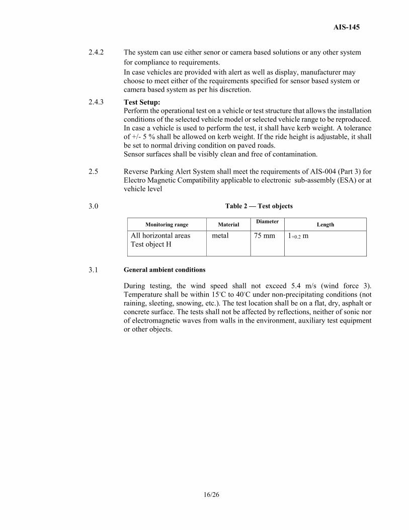
3.0 Table 2 — Test objects
Monitoring range Material Diameter Length
All horizontal areas Test object H
metal
75 mm 1+0.2 m
3.1 General ambient conditions
During testing, the wind speed shall not exceed 5.4 m/s (wind force 3). Temperature shall be within 15◦C to 40◦C under non-precipitating conditions (not raining, sleeting, snowing, etc.). The test location shall be on a flat, dry, asphalt or concrete surface. The tests shall not be affected by reflections, neither of sonic nor of electromagnetic waves from walls in the environment, auxiliary test equipment or other objects.
AIS-145
17/26
ANNEXURE 7
(See 5.6) REQUIREMENTS FOR VEHICLE REVERSE PARKING ALERT
(Applicable for category M and N not covered by annexure 6)
1. Definitions
1.1 “Vehicle reverse parking alert system (RPAS)” means a system that is designed to alert the driver about obstacles on the rear side of vehicles while parking in reverse
1.2
“Audible information and warning” means acoustical signal that is used to present information about relevant obstacles, to the driver eg. Pulses, Speech etc.
1.3 “Visual information and warning” means Optical signal which is used to present information about relevant obstacles to the driver eg. Telltale, Display, etc.
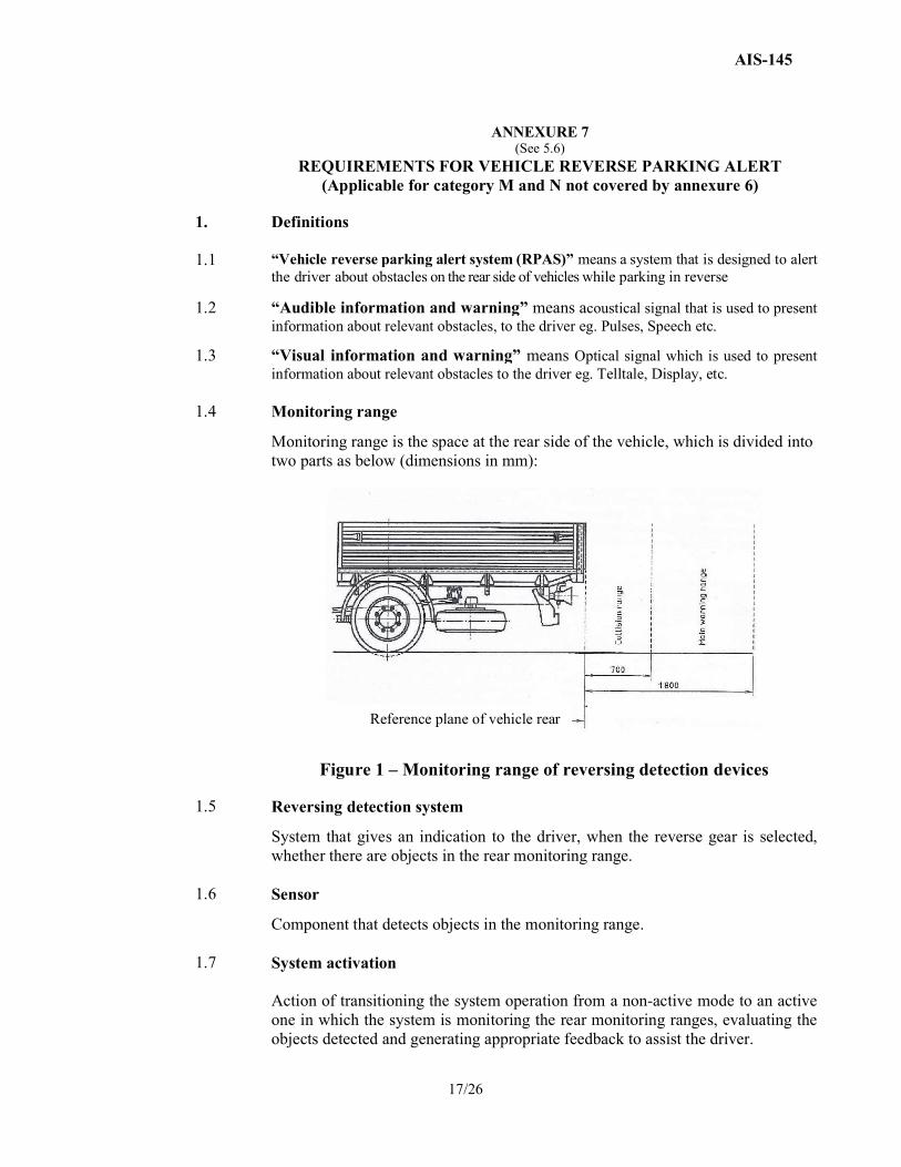
1.4 Monitoring range
Monitoring range is the space at the rear side of the vehicle, which is divided into two parts as below (dimensions in mm):
Figure 1 – Monitoring range of reversing detection devices
1.5 Reversing detection system
System that gives an indication to the driver, when the reverse gear is selected, whether there are objects in the rear monitoring range.
1.6 Sensor
Component that detects objects in the monitoring range.
1.7 System activation Action of transitioning the system operation from a non-active mode to an active one in which the system is monitoring the rear monitoring ranges, evaluating the objects detected and generating appropriate feedback to assist the driver.
Reference plane of vehicle rear
AIS-145
18/26
1.8 Test object
Object with a specific material, geometry and surface for testing the monitoring range.
1.9 Rear view camera
Rear view camera is a video camera which can continuously monitor the zone just behind the vehicle when activated.
1.10 Frame height
Height of the upper flank of the chassis frame at rear end of vehicle from the ground.
2.0 Functional and performance requirements
2.1 2.1.1 2.1.2 2.1.3 2.1.4 2.1.5
System activation and deactivation The RPAS shall be automatically activated whenever reverse gear is selected and the ignition switch is in ON condition. The RPAS system shall be automatically deactivated whenever a gear position other than reverse gear is selected. It shall not be possible to disable the RPAS by simply switching it off. The audible warning signal shall be maintained as described in clause no 2.4.1 On vehicles with automatic transmission the RPAS shall be deactivated if any gear position other that R (reverse gear) is selected.
2.2 Monitoring range
The monitoring range for RPAS is defined by the measuring points in figures 2, 3, 4 & 5 when the vehicle is in fully laden condition.
2.3 Arrangement of sensors
The sensors shall be arranged such that the monitoring range specified in clause no. 2.2 is covered.
2.4 Indicators & signals
The RPAS shall be equipped with audible warnings and optionally with visual indicators.
2.4.1 Audible warnings
The audible warnings shall have the functions given below –
2.4.1.1 The audible warning signals shall consist of –
a) Continuous sequence of individual tones when there are objects in the main warning zone
b) Continuous tone when there are objects in the collision zone
AIS-145
19/26
2.4.1.2 Faults
a) The faults in the system shall be indicated by a continuous tone and this tone shall differ markedly from the normal warning tones in its frequencies.
b) The warning tone shall have minimum duration of 3 seconds after selection of reverse gear. After sounding for the required period, the warning shall automatically switched off.
c) It shall only sound when the reverse gear is engaged & sound every time this gear is selected as long as the fault remains.
d) The warning signal shall not be cancelled unless the fault is rectified.
2.4.2 Visual indicators
Visual indicators if fitted shall be readily visible to the driver and may indicate messages related to one or more of the following:
a) Objects being in the main warning range or collision range,
b) System activation
c) System readiness
d) Faults
2.4.3 The vehicle manufacturer shall provide information on the method of operation of the audible warning and visual indicators in the user manual.
2.5 Rear View Camera System (optional fitment)
The rear view camera system shall display the zone behind the vehicle where an object may be present.
2.6 Electromagnetic Compatibility
The RPAS equipment shall comply with EMC requirements of AIS-004 (Part 3)
3.0 Tests
3.1 General test conditions
3.1.1 The desirable ambient conditions are
a) Ambient temperature: 15 to 40ºC
b) Relative Humidity: 60 ± 25%
c) Ambient wind speed: 5.4 m/s Max.
3.1.2 The test shall not be affected by reflected sounds from surrounding walls, auxiliary test equipment or other objects.
3.2 Test object
The monitoring range capability of the RPAS shall be tested with the following test objects:
a) Test object H for the horizontal test: plastic tube, grey, 75 mm diameter, 1000 mm length
b) Test object V for the vertical test: plastic tube, grey, 75 mm diameter, 300 mm length
The material of the tube for the test object may be different from the above specification with agreement between manufacturer & test agency.
AIS-145
20/26
3.3 Test procedure
3.3.1 Operational tests for compliance to the specified monitoring range shall be performed on a vehicle or on a test structure on which the installation conditions of the RPAS of the selected vehicle model or model range (in fully laden condition) can be reproduced.
3.3.2 Appropriate aids shall be used for identifying the test object positions.
3.3.3 A log shall be kept of the test positions where the object is detected and where the object is not detected.
3.4 Test 1 – Horizontal monitoring range test
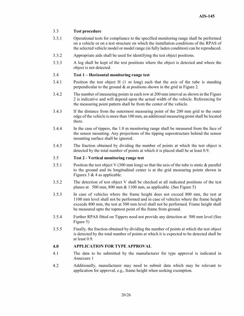
3.4.1 Position the test object H (1 m long) such that the axis of the tube is standing perpendicular to the ground & at positions shown in the grid in Figure 2.
3.4.2 The number of measuring points in each row at 200 mm interval as shown in the Figure 2 is indicative and will depend upon the actual width of the vehicle. Referencing for the measuring point pattern shall be from the center of the vehicle.
3.4.3 If the distance from the outermost measuring point of the 200 mm grid to the outer edge of the vehicle is more than 100 mm, an additional measuring point shall be located there.
3.4.4 In the case of tippers, the 1.8 m monitoring range shall be measured from the face of the sensor mounting. Any projections of the tipping superstructure behind the sensor mounting surface shall be ignored.
3.4.5 The fraction obtained by dividing the number of points at which the test object is detected by the total number of points at which it is placed shall be at least 0.9.
3.5 Test 2 - Vertical monitoring range test
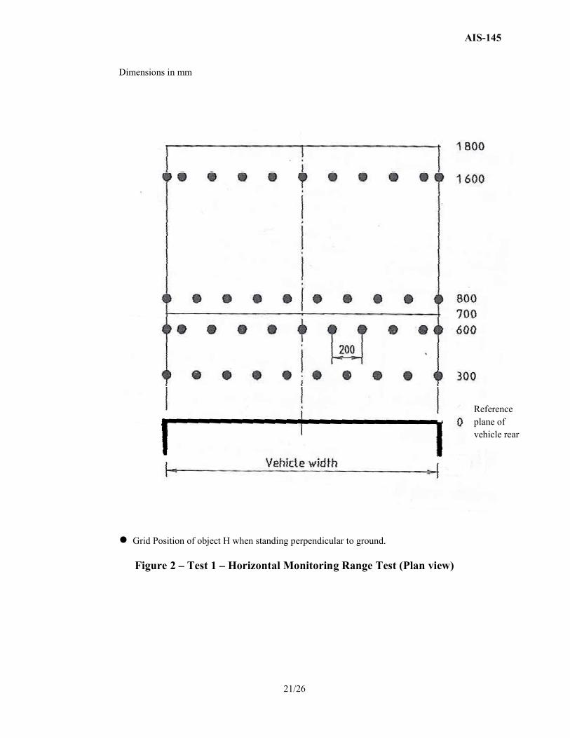
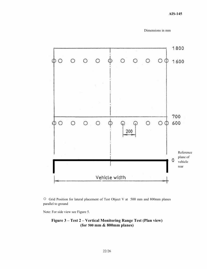
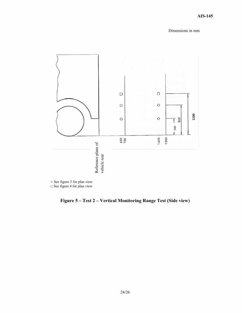
3.5.1 Position the test object V (300 mm long) so that the axis of the tube is static & parallel to the ground and its longitudinal center is at the grid measuring points shown in Figures 3 & 4 as applicable.
3.5.2 The detection of test object V shall be checked at all indicated positions of the test planes at 500 mm, 800 mm & 1100 mm, as applicable. (See Figure 5)
3.5.3 In case of vehicles where the frame height does not exceed 800 mm, the test at 1100 mm level shall not be performed and in case of vehicles where the frame height exceeds 800 mm, the test at 500 mm level shall not be performed. Frame height shall be measured upto the topmost point of the frame from ground.
3.5.4 Further RPAS fitted on Tippers need not provide any detection at 500 mm level (See Figure 5)
3.5.5 Finally, the fraction obtained by dividing the number of points at which the test object is detected by the total number of points at which it is expected to be detected shall be at least 0.9.
4.0 APPLICATION FOR TYPE APPROVAL
4.1 The data to be submitted by the manufacturer for type approval is indicated in Annexure 1
4.2 Additionally, manufacturer may need to submit data which may be relevant to application for approval, e.g., frame height when seeking exemption.
AIS-145
21/26
Dimensions in mm
● Grid Position of object H when standing perpendicular to ground.
Figure 2 – Test 1 – Horizontal Monitoring Range Test (Plan view)
Reference plane of vehicle rear
AIS-145
22/26
Dimensions in mm
○ Grid Position for lateral placement of Test Object V at 500 mm and 800mm planes parallel to ground Note: For side view see Figure 5.
Figure 3 – Test 2 – Vertical Monitoring Range Test (Plan view) (for 500 mm & 800mm planes)
Reference plane of vehicle rear
AIS-145
23/26
Dimensions in mm
□ Grid Position for lateral placement of Test Object V at 1100mm plane parallel to ground Note: For side view see Figure 5.
Figure 4 – Test 2 – Vertical Monitoring Range Test (Plan view) (for 1100mm plane)
Reference plane of vehicle rear
AIS-145
24/26
Dimensions in mm
○ See figure 3 for plan view □ See figure 4 for plan view
Figure 5 – Test 2 – Vertical Monitoring Range Test (Side view)
Ref
eren
ce p
lane
of
vehi
cle
rear
1100
500
AIS-145
25/26
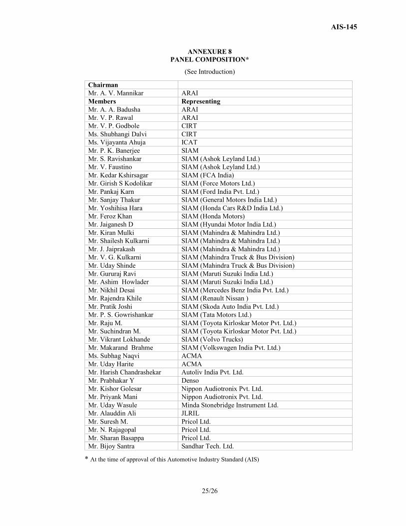
ANNEXURE 8 PANEL COMPOSITION*
(See Introduction)
Chairman Mr. A. V. Mannikar ARAI Members Representing Mr. A. A. Badusha ARAI Mr. V. P. Rawal ARAI Mr. V. P. Godbole CIRT Ms. Shubhangi Dalvi CIRT Ms. Vijayanta Ahuja ICAT Mr. P. K. Banerjee SIAM Mr. S. Ravishankar SIAM (Ashok Leyland Ltd.) Mr. V. Faustino SIAM (Ashok Leyland Ltd.) Mr. Kedar Kshirsagar SIAM (FCA India) Mr. Girish S Kodolikar SIAM (Force Motors Ltd.) Mr. Pankaj Karn SIAM (Ford India Pvt. Ltd.) Mr. Sanjay Thakur SIAM (General Motors India Ltd.) Mr. Yoshihisa Hara SIAM (Honda Cars R&D India Ltd.) Mr. Feroz Khan SIAM (Honda Motors) Mr. Jaiganesh D SIAM (Hyundai Motor India Ltd.) Mr. Kiran Mulki SIAM (Mahindra & Mahindra Ltd.) Mr. Shailesh Kulkarni SIAM (Mahindra & Mahindra Ltd.) Mr. J. Jaiprakash SIAM (Mahindra & Mahindra Ltd.) Mr. V. G. Kulkarni SIAM (Mahindra Truck & Bus Division) Mr. Uday Shinde SIAM (Mahindra Truck & Bus Division) Mr. Gururaj Ravi SIAM (Maruti Suzuki India Ltd.) Mr. Ashim Howlader SIAM (Maruti Suzuki India Ltd.) Mr. Nikhil Desai SIAM (Mercedes Benz India Pvt. Ltd.) Mr. Rajendra Khile SIAM (Renault Nissan ) Mr. Pratik Joshi SIAM (Skoda Auto India Pvt. Ltd.) Mr. P. S. Gowrishankar SIAM (Tata Motors Ltd.) Mr. Raju M. SIAM (Toyota Kirloskar Motor Pvt. Ltd.) Mr. Suchindran M. SIAM (Toyota Kirloskar Motor Pvt. Ltd.) Mr. Vikrant Lokhande SIAM (VoIvo Trucks) Mr. Makarand Brahme SIAM (Volkswagen India Pvt. Ltd.) Ms. Subhag Naqvi ACMA Mr. Uday Harite ACMA Mr. Harish Chandrashekar Autoliv India Pvt. Ltd. Mr. Prabhakar Y Denso Mr. Kishor Golesar Nippon Audiotronix Pvt. Ltd. Mr. Priyank Mani Nippon Audiotronix Pvt. Ltd. Mr. Uday Wasule Minda Stonebridge Instrument Ltd. Mr. Alauddin Ali JLRIL Mr. Suresh M. Pricol Ltd. Mr. N. Rajagopal Pricol Ltd. Mr. Sharan Basappa Pricol Ltd. Mr. Bijoy Santra Sandhar Tech. Ltd.
* At the time of approval of this Automotive Industry Standard (AIS)
AIS-145
26/26
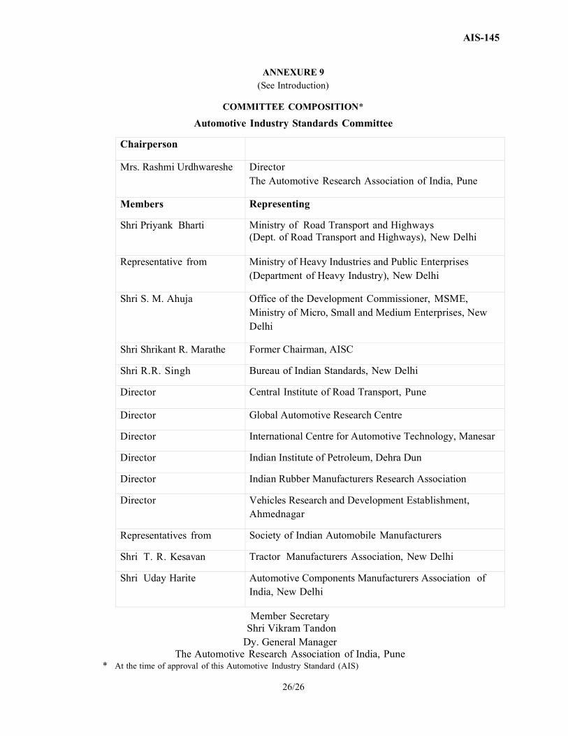
ANNEXURE 9
(See Introduction)
COMMITTEE COMPOSITION*
Automotive Industry Standards Committee
Chairperson
Mrs. Rashmi Urdhwareshe Director The Automotive Research Association of India, Pune
Members Representing
Shri Priyank Bharti Ministry of Road Transport and Highways (Dept. of Road Transport and Highways), New Delhi
Representative from Ministry of Heavy Industries and Public Enterprises (Department of Heavy Industry), New Delhi
Shri S. M. Ahuja Office of the Development Commissioner, MSME, Ministry of Micro, Small and Medium Enterprises, New Delhi
Shri Shrikant R. Marathe Former Chairman, AISC
Shri R.R. Singh Bureau of Indian Standards, New Delhi
Director Central Institute of Road Transport, Pune
Director Global Automotive Research Centre
Director International Centre for Automotive Technology, Manesar
Director Indian Institute of Petroleum, Dehra Dun
Director Indian Rubber Manufacturers Research Association
Director Vehicles Research and Development Establishment, Ahmednagar
Representatives from Society of Indian Automobile Manufacturers
Shri T. R. Kesavan Tractor Manufacturers Association, New Delhi
Shri Uday Harite Automotive Components Manufacturers Association of India, New Delhi
Member Secretary Shri Vikram Tandon
Dy. General Manager The Automotive Research Association of India, Pune * At the time of approval of this Automotive Industry Standard (AIS)