Embed Size (px)
Citation preview

4-CYCLE MODEL ENGINES
R-9/2800-200 AUTHENTIC SCALE MARK I SERIES
SCALE 9 CYLINDER (200 CC) RADIAL ENGINE
OPERATING, MAINTANCE AND SAFETY MANUAL
VOLUME 1 REVISION 4

CAUTION before attempting to mount and run
your engine on a test stand or aircraft, this manual should be completely read and understood. If you have any questions, concerns or things that you do not fully understand, you should contact the Customer Services Department at PEGASUS AIRCRAFT ENGINES, 1-888-898-7841 between the hours of 9:00 AM and 5:00 PM, EST, Monday through Friday. You can also send an email to [email protected].
CONGRATULATIONS, you have purchased one of the finest
miniature radial engine available on the market today! The PEGASUS AIRCRAFT ENGINES R-9/2800-200 radial engine is an almost exact replica of the front half of the full scale Pratt & Whitney R2800 TWIN WASP radial engine. The engine is a total of 200cc in 9 cylinders and is 1/5th scale. All PEGASUS AIRCRAFT ENGINES are CNC machined from high quality, alloy bar stocks and have unsurpassed fit and finish. Unlike other engines offered on the market today, the PEGASUS AIRCRAFT ENGINES line of engines are completely assembled in the USA using the highest quality materials and components available. PEGASUS AIRCRAFT ENGINES has developed one of the best customer support programs offered by any engine manufacturer. When you call or email our Customer Services, you will be in contact with an expert on your particular engine not a lay person hired to answer the phone. What ever problem you are experiencing or question you may have will be addressed quickly and expertly by one of PEGASUS AIRCRAFT ENGINES qualified representatives.
WARNING this miniature engine is not a toy but
rather a power source for the propulsion of an R/C aircraft. It is expressly forbidden to use this engine to power any manned or human carrying aircraft or vehicle. Any misuse, abuse, incorrect handling or crash damage can cause the engine to malfunction. Such malfunctions could result in injuries to you and bystanders as well as damage to the aircraft and property. In any of the above mentioned situations, the engine should be returned to the factory or an authorized repair station for evaluation and repair before reinstalling on the aircraft for continued use.
Minimum age for operating this engine is 14 years of age. Young people should be accompanied by an older, more experienced R/C modeler. Miniature engines have all the trappings of the full scale engines such as becoming extremely hot when operating or after shut down. First, second and third degree burns are a real possibility. Fuel, oil fluids and exhaust emissions can be considered toxic. You should understand the hazards of gasoline and be cautious not to allow it to come into contact your eyes. Do not ingest even the smallest amount. Washing your hands after contact with model fuel is strongly suggested. Always keep fuel out of the reach of children and pets. Propellers are extremely dangerous whether they are full scale or model. Caution should be exercised at all times when the engine is running.

RIGGING YOUR ENGINE FUEL SYSTEM: To rig your R9 engine for fuel, first you will need a 32 to 50 ounce fuel tank. The fuel tank must be adapted to use gasoline. Your local hobby dealer can sell you the necessary parts to accomplish this. All fuel lines need to be Tygon flexible fuel tubing or gasoline compatible equivalent. When rigging the fuel lines, run a line from the pickup port on the fuel tank to the electric fuel pump (end with hex). Next run a line from the fuel pump (flat end) to the port on the side of the carburetor. The top port (on the carburetor) is a vent that allows the diaphragm in the carburetor to work. If using a fuel filter, make sure it is gasoline compatible and install it between the fuel tank and the fuel pump. The vent line on the fuel tank needs a large loop of line affixed to the top of the fuel tank and then exit on the outside of the airplane. The large loop (on top of the fuel tank) insures that the vent line will not leak fuel. No pressure line is required. Ad a third line to the fuel tank with a stopper on the end. This line is used to fill the tank with fuel. The fuel pump should be powered by a 6 to 12 volt battery. 2000 to 5000 mAh NiCad, NMH or LiPo is recommended. If using the larger mAh battery, the one battery can be used for both the fuel pump and the CDI ignition system. It is recommended to have a separate on/off switch for the fuel pump. This allows you to prime the engine without the ignition being on. IGNITION SYSTEM: When rigging the CDI ignition box to your engine, start by determining which cylinder is #1 cylinder. Hold the engine with the scale magneto facing straight up. The scale magneto is the black part between the two scale distributors (round, silver canisters) on the nose cone housing of the engine. With the engine in this position, look at the bottom most cylinder of the 9 cylinders. This is #1 cylinder. The spark plug wires starts at #1 cylinder and progresses in a counter clockwise direction (when looking at the front of the engine, propeller end).

Place #1 spark plug wire on #1 cylinder’s spark plug and #2 spark plug wire on #2 cylinder’s spark plug (just to the right of #1 when looking at the front of the engine). Continue this progression until you have all spark plug wires installed. Install the grounding leads that are sleeved to the spark plug wires by first attaching the lead to the upper most screw on the intake tube’s brass retainer ring. Next install the other end of the grounding lead wire to the ground wire on the CDI ignition box. This is a black wire protruding from the ignition box with a ring connector affixed to the end of the wire. All nine grounding leads need to be attached to the ring connector on the ignition box ground wire using a small bolt, 2 washers, lock washer and nut. On later models, the ignition box has a nine lead extension with bullet connectors for greater ease of rigging. The CDI ignition is powered by a 6 to 8.4 volt battery. 2000 to 5000 mAh NiCad, NMH or LiPo battery is recommended. As stated above, one battery can be used if it is a high capacity battery (5000 mAh) for both the ignition and fuel pump (not to exceed 8.4 volt). If using one battery, it is recommended to check the amount of charge in the battery between flights. A separate switch (from the fuel pump) is recommended for the ignition system. Also recommended is transmitter operated switches (one for the ignition & one for the fuel pump) that will allow you to kill the engine remotely in case of an emergency. See diagram below for the engine’s suggested fuel and ignition rigging in your airplane.
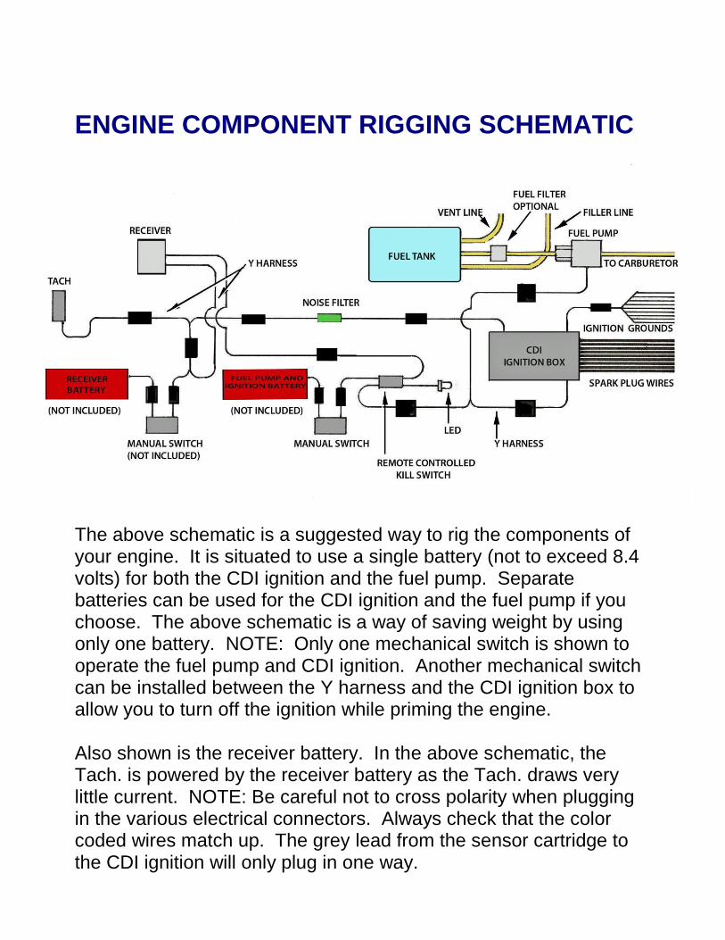
ENGINE COMPONENT RIGGING SCHEMATIC
The above schematic is a suggested way to rig the components of your engine. It is situated to use a single battery (not to exceed 8.4 volts) for both the CDI ignition and the fuel pump. Separate batteries can be used for the CDI ignition and the fuel pump if you choose. The above schematic is a way of saving weight by using only one battery. NOTE: Only one mechanical switch is shown to operate the fuel pump and CDI ignition. Another mechanical switch can be installed between the Y harness and the CDI ignition box to allow you to turn off the ignition while priming the engine. Also shown is the receiver battery. In the above schematic, the Tach. is powered by the receiver battery as the Tach. draws very little current. NOTE: Be careful not to cross polarity when plugging in the various electrical connectors. Always check that the color coded wires match up. The grey lead from the sensor cartridge to the CDI ignition will only plug in one way.

STARTING THE PEGASUS RADIAL ENGINE
All radial engines have an inherent tendency to possibly become hydraulically locked. This means that the 3 bottom cylinders can become flooded with fuel and oil causing the engine not to turn over. Before attempting to start the engine, always roll the engine through several revolutions (making sure the ignition is turned off before rotating). If the engine does not want to rotate past a certain point, do not try to force it. At this time, you will need to remove the spark plugs from the 3 bottom cylinders and rotate the engine until all excess fuel and oil is pumped out the spark plug hole. Reinstall the spark plugs and continue the starting procedure. When the engine is cold, first be sure the Ignition switch is off, the fuel pump is on and the choke is closed. Flip the prop approximately 5 times. This will prime the engine with fuel. Next with the choke in the open position, set the throttle to about ¼ throttle. Turn the ignition switch on and start the engine. To insure that all cylinders are firing, you can use a temperature gun to check the exhaust temperature near the cylinder head. All cylinders should be similar in temperature and the engine running smoothly. To start the engine when it is hot or warm, first turn the fuel pump on and the ignition off, close the choke and flip the prop 2 or 3 times. Open the choke, turn the ignition on and set the throttle just above idle to start the engine. Our test engines usually start with one flip of the propeller blade.
OPERATING AND TUNING Operating and tuning your PEGASUS AIRCRAFT ENGINES radial
engine is not difficult but requires attention to carburetor tuning, propeller choice, periodic valve adjustment & lubrication, correct (fresh) fuel and overall awareness of its general condition.

Fuel for your radial engine should be a high quality gasoline of at
least 91 octane. The recommended oil is Klotz KL-189 and should be mixed 50:1 for break and normal use. Adding nitro methane or methanol for any reason will not enhance the engine’s performance but rather cause undue wear, overheating and the voiding of your warranty. Starting with the carburetor adjustments, both the high speed and low speed needle valves are pre set at the factory for correct fuel delivery under normal operating conditions (air temperature, barometric pressure and elevation). The elevation of your location is important to properly tuning your carburetor. The elevation of the PEGASUS TECHNOLOGY factory is 188’ above sea level. You can find out the elevation of your area by calling your local airport. Depending on your location, minor adjustments may need to be made but major adjustments are a mistake. Minor adjustments usually consist of no more than 1/8 turn in either direction of the low and high speed needles valves. If you loose your place (with the needle valves) the low speed needle is 2 turns out (counter clockwise) and the high speed needle is 6 turns out (counter clockwise) from completely closed. This is the factory settings. It is critical to insure that your linkage and servo throw do not allow the throttle plate to move past center line (FULL OPEN POSITION)!!. This could cause an unsafe loss of power and or stall of engine. It is important to use a stiff linkage rod to prevent High G forces from flexing the linkage rod into a position that could allow the throttle plate to move past full open position!! For the start up and initial break-in period of your engine, be sure the fuel to oil ratio is 50:1. Run the engine at approximately 1/2 throttle for at least 4 tanks of fuel (32 oz or 1000 ml per tank). During this period, vary the throttle up and down slightly. Run the engine 5 to 10 minutes at a time letting it cool down between runs. Do not try to idle the engine during the first 15 minutes of break-in as doing so can cause an adverse and degenerating affect on the cam, cam lobes and cam followers.

To properly adjust the engine after a break-in period of at least 1 US gallon of fuel, bring the engine to full throttle. Using a tachometer, lean the engine (using the high speed needle) until it turns its highest RPM (never more than 4200 RPM depending on prop selection). Do not attempt to lean the engine to produce more than 4200 RPM. The electronic ignition has a built in rev limiter preset at 5100 RPM but this setting is only for safety purposes. It is not meant to be the maximum RPM setting for the engine.
After the engine is turning the recommended RPM (without loosing
RPM), turn the high speed needle valve counter clockwise 1/8 turn. This will insure the engine has sufficient fuel when the aircraft starts
accelerating forward and the prop loads by cutting through clean air instead of cavitating the air when run in a static situation.
Once you have the high speed needle valve set and the break in
period is complete, the low speed needle valve can now be adjusted. A common misconception is that the low speed needle valve only affects the idle performance of the engine. In reality, the low speed needle valve affects both the idle and mid range of the engine. The high speed needle valve only affects peak power settings. If the engine idles rough and is sluggish when the throttle is advanced, the low speed needle valve needs to be leaned (turn clockwise no more than 1/8 of a turn initially). Continue turning the low speed needle clockwise in 1/16 turn increments until the engine idles smoothly (app. 750 RPM) without trying to die and responds fast and crisp to throttle advance. Between each adjustment, the engine needs to be revved up to clear out excess fuel and oil.
At this point your engine is adjusted well enough to make the first flight. Further “tweaking” of the high and low speed needles may be necessary to get the ideal performance for your area. As the seasons change, adjustments may be necessary to keep the engine

running at peak performance. In cold weather the air is denser thus more fuel is needed and in hot weather, the opposite applies.
FRESH AIR INTAKE
When using an engine cowling, such as in the case of most WWII fighter planes, a fresh air intake must be established on the outside
of the fuselage. This is necessary due to hot, contaminated air inside the cowling. In testing we have found that the engine will loose power and RPM if a fresh air source is not supplied to the carburetor. In fabricating a fresh air source for your engine, a plenum area must be established just in front of the carburetor. This consists of a box area that is considerably larger than the carburetor’s intake throat. If a plenum area is not used, it will cause the engine to loose power and RPM plus not respond well to throttle increases. Periodic maintenance and inspection is a must on this very complex engine. Your radial engine should be inspected periodically, approximately every 1 hour of run time, for loose fasteners (bolts, nuts, screws, etc.). Checking the tightness of all fasteners is a good ideal. Never over tighten any fastener. The screws and nuts are very small (to obtain the scale look of the full scale engine). After 20 hours of run time, all the screws holding the cylinders to the crankcase need to be replaced. These screws are sold in sets and are not covered by the warranty as they are considered expendable items. Go to the parts exploded view to find screws and

reference number to the parts list. When installing the cylinder hold down screws always use a good grade of RED thread locker. For all other screws use BLUE thread locker. Re-lubricating the rocker arms should be done after every 10 hours of run time. The rocker arms should be lubed with a high grade, thick Molly lube.
Be cautious not to over lubing the rocker arms. Too much lube will fill the pushrod tubes and hurt performance. A good idea is to keep a log of run time on your engine. This will help you know when to lube the rockers, adjust the rockers, inspect the engine, etc. For your convenience, we have enclosed a log book with your engine.
Also check for loose components by observing if any black residue is
omitting from between parts and components of the engine. This black residue is finely ground metal mixed with oil that seeps from between engine parts when the parts are loose or not sufficiently tight. DO NOT run the engine until this situation is properly addressed. Valve Rocker adjustment is a critical part of your engine’s performance. To ignore adjusting the rockers will lead to excessive wear of the valve train and considerable loss of performance. Adjusting the intake and exhaust rockers of each cylinder is relatively easy to do but requires attention to finesse. If the rockers are too loose the engine will loose performance and be hard to start. If the rockers are too tight, it will cause excessive wear and engine failure. The rockers need to be adjusted after the break in period is completed and then every 10 hours there after.
To adjust the valves, start by removing the rocker covers and spark plugs from the cylinder heads. While looking through the spark plug hole, rotate the crankshaft until the piston comes to TDC (top dead center) with both rocker arms in the horizontal position (both valves closed). You will note that both rocker arms are slightly loose in this position. This should be the combustion stroke where you can rock the crankshaft side to side without the rockers moving. If the rockers move immediately when the crankshaft is slightly rocked either way, this is between the exhaust stroke and intake stroke. This position should not be used to adjust the valves as it is easy to make a mistake in this position.
Using a box end (closed end) 7mm wrench and a 2mm socket head
wrench (Allen wrench), loosen either of the rocker arms one at a time. Completely adjust one rocker arm and retighten before starting on the other. Either the exhaust side or intake side can be adjusted first. The sequence does not matter.
The adjustment starts by loosening the adjuster screw’s lock nut with a box end 7mm wrench while holding the adjuster screw in place with a 2.5mm socket head wrench. The engine needs to be completely cooled down to room temperature (app. 70°) before starting the rocker adjustments. At this point, turn the adjuster screw down (clockwise) until it just removes all slack from the rocker. A feeler gage is not necessary for these adjustments. Be cautious not to turn the adjuster screw too far as you only want the slack removed. When you are satisfied that all the slack is removed, tighten the lock nut while holding the adjuster screw firmly in place with the Allen wrench. In some cases, tightening the lock nut will change the setting you have established. If this occurs, loosen the lock nut and start the procedure over until the setting stays constant after the lock nut is tightened.

Use the same procedure to adjust the other rocker arm. With both rocker arms adjusted, replace the rocker covers. Use blue thread locker on the rocker cover’s screws. The rocker cover’s screws are very small, do not over tighten them. Now proceed to adjust the remaining valves using the same procedure described above. Always do only one cylinder at a time.
ENGINE SPECIFICATIONS
Type Radial, Gasoline, CDI Spark Ignition
Scale 1/5th
Cylinders 9
Cooling Air
Engine Displacement 12.2 cu. in. (200 cc)
Capacity Per Cylinder 1.33 cu. in. (22.22 cc)
Bore 29 mm
Stroke 32 mm
Power 15 hp
RPM Range 750-4200
Maximum RPM 4200
Engine Diameter 281 mm
Engine Length 275 mm
Weight w/o prop 13 lbs.
Fuel Usage 2.5 oz Per Minute
Recommended 2 blade Propellers
32-14 Xoar (for break-in), 32-16 Xoar & 32-18 Xoar
Carburetor 1 Zama
Exhaust Stainless Steel Collector Ring w/smoke oil nipple (included)

SAFETY WARNINGS *This model engine is not a toy! It is a sophisticated power
system to power model aircraft and should never be used for any other purpose.
*Keep all loose items away from the propeller when the
engine is running.
*Never reach over the propeller to tune or adjust the engine while
the engine is running.
*Keep bystanders at least 30’ away while engine is running.
*When the engine is running, it becomes very hot. Never touch
the engine or exhaust as severe burns can result.
*Never operate engine with a damaged propeller. The propeller
can come apart or disintegrate and cause severe injury to yourself and bystanders.
*Keep children and pets at least 30’ away while engine is running.
*Never be in front of the propeller while engine is running.
*Make sure the propeller is tight and secure before starting the
engine.
*Always have a helper hold the airplane securely in place before
starting the engine.
*Never throw a rag or other objects into the propeller to kill the
engine. Install engine kill switch on the transmitter or airplane to kill the engine.
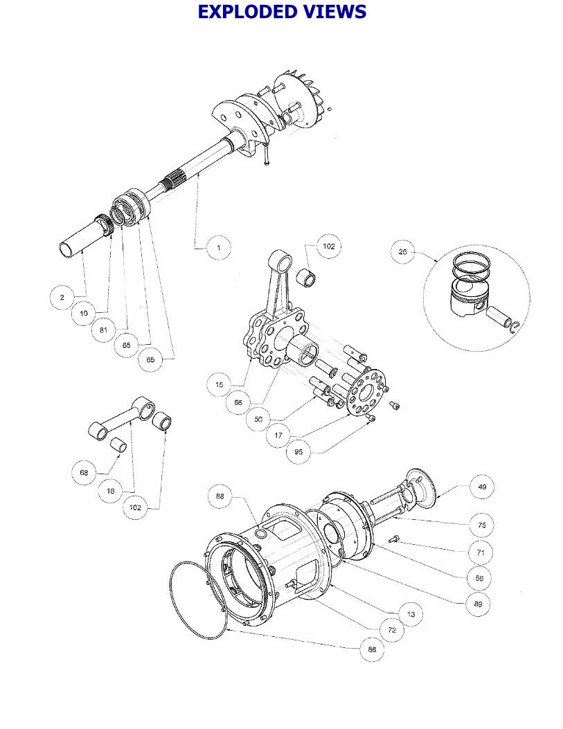
EXPLODED VIEWS


REPLACEMENT PARTS LIST
Parts numbers are for 1 each or 1 set as noted. For current prices go to www.pegasusengine.com or call 1-888-898-7841.
ITEM NUMBER
QTY. PART NUMBER
PART NAME
1 1 AS-21-901 CRANK SHAFT
2 1 AS-21-902 CRANKSHAFT SLEEVE
3 1 AS-21-903 NOSE CONE
4 1 AS-21-904 SCALE MAGNETO
5 2 AS-21-905 SCALE DISTRIBUTOR
6 1 AS-21-906 SCALE PROP CONTROLLER
7 1 AS-21-906A SCALE PROP GOVERNOR, ROLLER WHEEL
8 1 AS-21-907 SCALE OIL PUMP
9 1 AS-21-909 CAM
10 1 AS-21-910 CRANK SHAFT DRIVE GEAR
11 1 AS-21-911 CAM SECTION CRANKCASE
12 1 AS-21-912 CRANKCASE CORE
13 1 AS-21-913 INLET AND MOUNT
14 18 AS-21-914 CAM FOLLOWER
15 1 AS-21-915 MASTER ROD
16 8 AS-21-916 CONNECTING ROD
17 1 AS-21-917 LINK PIN RETAINING PLATE
18 18 AS-21-919 CAM FOLLWER BUSHING
19 1 AS-21-921 CRANKSHAFT COUNTER WEIGHT
20 3 AS-21-922 COUNTERWEIGHT RIVETS
21 1 AS-21-924 EXHAUST COLLECTOR RING
22 1 AS-21-925 CAM DRIVE 35-10 GEAR_2 EA.
23 2 AS-21-929 FAN BOLT WASHER
24 9 AS-21-C00 CYLINDER HEAD, FRONT
25 9 AS-21-C02 PISTON ASSEMBLY
26 1 AS-21-C03 PROP HUB OUTER PLATE
27 1 AS-21-C04 PROP HUB-2 BLADE PROP
28 1 AS-21-C05 PROP HUB NUT

ITEM NUMBER
QTY. PART NUMBER
PART NAME
29 1 AS-21-C06 CRANKSHAFT KEY
30 2 AS-21-C11 CAM IDLER GEAR SPACE
31 9 AS-21-C12 CYLINDER SLEEVE
32 36 AS-21-C13 10MM STUD, NOSE, SCALE MAG, DISTRIB
33 18 AS-21-C15 STUD, NOSE CONE 31MM
34 9 AS-21-C16A EXHAUST PUSH ROD 72MM
35 9 AS-21-C16B INTAKE PUSH ROD
36 9 AS-21-C17A EXHAUST GUIDE TUBE 65MM
37 9 AS-21-C17B INTAKE GUIDE TUBE 64MM
38 36 AS-21-C18 PUSH ROD TUBE SCALE NUT
39 18 AS-21-C20 ROCKER
40 18 AS-21-C21 ROCKER ADJUSTER SCREW
41 18 AS-21-C22 ROCKER ADJUSTER BALL
42 18 AS-21-C23 ROCKER COVER
43 18 AS-21-C24 VALVE 13 MM DIA.
44 18 AS-21-C25 VALVE GUIDE
45 18 AS-21-C26 VALVE SPRING CAP
46 18 AS-21-C27 EXHAUST STUB TUBE
47 18 AS-21-C28 INLET TUBE
48 36 AS-21-C29 INLET AND EXHAUST CLAMP
49 1 AS-21-C30 VELOCITY STACK 19MM
50 8 AS-21-C33 LINK PIN
51 18 AS-21-C34 VALVE SPRING
52 9 AS-21-C36 SCALE SPARK PLUG
53 18 AS-21-C37 SCALE IGNITION RING WIRE ADAPTOR
54 1 AS-21-C44 INLET FAN
55 1 AS-21-C45 CAM RETAINING PLATE
56 1 AS-21-C48 SENSOR CARTRIDGE 16 DIA.
57 1 AS-21-C52 CARB INSULATOR BLOCK
58 18 AS-21-C62 CAM FOLLOWER (ROLLER SHAFT)
59 18 AS-21-C63 CAM FOLLOWER (ROLLER)
60 18 AS-21-C64 ROCKER PIN
61 18 AS-21-C65 ROCKER PIN SLEEVE
62 1 AS-21-C66 CAM BUSHING

ITEM NUMBER
QTY. PART NUMBER
PART NAME
63 9 AS-21-C67 CYLINDER SCALE OIL PIPE
64 1 AS-21-P001 SEALED BALL BEARING 17X35X10
65 2 AS-21-P002 BALL BEARING, 20X37X9
66 1 AS-21-P003 MASTER ROD BEARING, 15X21X16
67 36 AS-21-P004 ROCKER BEARING, 4X7X3
68 8 AS-21-P006 LOWER ROD BUSHING, 6X8X10
69 109 AS-21-P007 M2 X6, CYLINDER
70 112 AS-21-P008 M2 X 5MM SCREWS, ROCKER COVER AND SCALE OIL PUMP
71 12 AS-21-P009 M3 X 10 SCREWS, SENSOR CARTRIDGE
72 9 AS-21-P010 SCREWS,REAR MOUNT
73 4 AS-21-P011 M3X30 SCREWS, SCALE DISTRIBUTOR
74 116 AS-21-P012 M2 SCREWS, INTAKE CLAMP, SCALE OIL PUMP
75 2 AS-21-P014 M5X45 CARB SCREWS
76 6 AS-21-P015 M4X45 PROP BOLTS
77 9 AS-21-P016 ¼ X 32 SPARK PLUG
78 54 AS-21-P017 M2 NYLOC NUT, FRONT STUDS
79 19 AS-21-P018 M3 NYLOC NUT, FAN BOLT, ROCKER PIN
80 18 AS-21-P019 M4 LOCK NUT, ROCKER ADJUST SCREW
81 1 AS-21-P020 20MM, EXTERNAL CIRCLIP
82 1 AS-21-P021 RETAINER, 15MM, WRIST PIN
83 1 AS-21-P022 C CLIP 5MM, CAM IDLER GEAR SHAFT
84 1 AS-21-P023 INTERNAL CIRCLIP 35MM, CRANK MAIN BEARING
85 18 AS-21-P024 E CLIP, 0.125”, VALVE
86 3 AS-21-P025 O RING 95 ID X 1.78, CAM HOUSING, REAR MOUNT
87 9 AS-21-P026 O RING 30 ID X 1.78, CYLINDER
88 27 AS-21-P027 O RING 10.8 ID X 1.78, INLET
89 1 AS-21-P028 O RING 70 ID X 1.78, SENSOR CARTRIDGE

ITEM NUMBER
QTY. PART NUMBER
PART NAME
90 18 AS-21-P030 O RING 4.00 OD X .75 CS, CAM FOLLOWER
91 1 AS-21-P032 MAGNET 3 X 3, USE SOUTH POLE
92 1 AS-21-P033 CDI IGNITION KIT FOR ¼ X 32 SPARK PLUG
93 1 AS-21-P035 CARB
94 1 AS-21-P037 M3 X 25 FAN BOLT
95 3 AS-21-P039 M2.5 X 5MM SCREWS, MASTER ROD RETAINING PLATE
96 4 AS-21-P040 M3 X 16 SOCER HEAD CAP SCREW, TRIGGER RING
97 4 AS-21-P044 COPPER RIVET 0.8 X 5, DATA PLATE
98 1 AS-21-P045 P&W LOGO PLATE
99 1 AS-21-P046 ENGINE DATA PLATE
100 18 AS-21-P050 ROCKER ARM PIN WASHER
101 1 AS-21-P051 IDLER GEAR BUSHING 5X10X12
102 9 AS-21-P052 WRIST PIN BUSHING 6X8X10
103 1 AS-21-P053 ELECTRIC FUEL PUMP, 3 PSI
104 1 AS-21-PO54 SET SCALE SPARK PLUG WIRES TYPE 1
105 1 AS-21-PO55 ENGINE LOG BOOK
106 1 AS-21-PO56 “Y” HARNESS, 375 MM,PUMP SHUT OFF
107 1 AS-21-PO57 LIPO BATTERY, 7.4 V-5000 MAH
108 9 AS-21-PO58 SET SPARK PLUGS ¼-28
109 1 AS-21-PO59 OPTIONAL KILL SWITCH (ELECTRIC FUEL PUMP)
110 1 AS-21-PO60 OIL PEN
111 1 AS-21-PO61 MINI TACHOMETER
112 1 AS-21-PO62 POWER SWITCH AND CHARGER PORT HARNESS
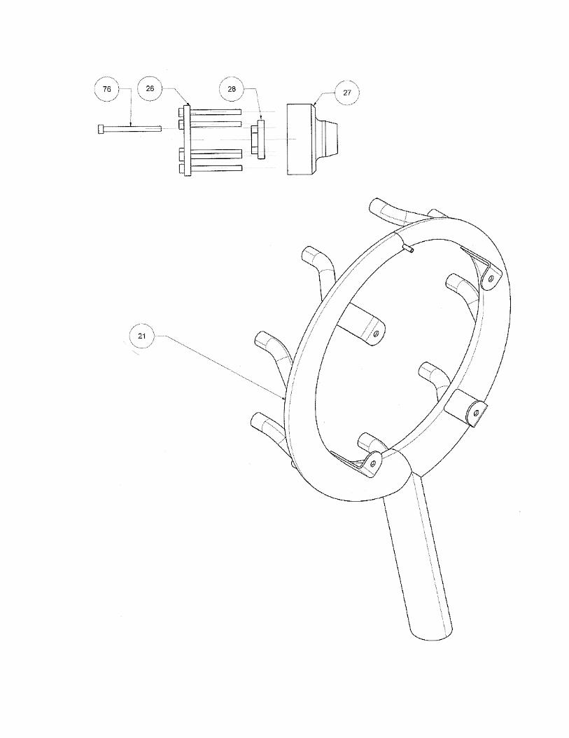
ADJUSTABLE PITCH PROPELLERS MOUNTING THE ADJUSTABLE PROPELLER HUB: To remove the 2 blade prop hub, use a rubber strap tool (such as used to remove automobile oil filters) to hold the hub while removing the nut from the center of the hub. The nut turns counter clockwise to remove. Do not use pliers, vise grips, etc to hold the hub. This will cause the hub to be unbalanced and can cause engine damage. After the 2 blade hub is removed, you can now install the 3 or 4 blade hub. Start by first removing the cir clip from inside the hub. Next, install the hub and tork the nut to 25 ft lbs of tork. It is important to use a tork wrench because over tightening the nut can crush the bearing spacer inside the engine. The cir clip can now be installed.
ADJUSTING THE PROPELLER HUB: The 3 blade and 4 blade prop hubs are statically adjustable. The pitch of the propeller blades can be adjusted over a wide range of degrees from fine pitch to course pitch. CAUTION: if the propeller blades are adjusted too fine or too course, the propeller will not develop sufficient thrust to pull your airplane at an acceptable speed (considerably above stall speed). NOTE: The 4 blade propeller must be set with less pitch than the 3 blade propeller if used in the same application. This is due to the increased thrust capabilities of the 4 blade propeller. The 4 blade propeller also takes more power to pull when using the same pitch as the 3 blade propeller. To adjust the pitch of the propeller blades, first start by removing the nose cone from the hub. Next loosening all the hub screws. The blades can now be moved. Start by turning the adjuster wheel inside the hub, left (counter clockwise) for less pitch and right (clockwise) for more pitch. Turn the adjuster wheel until it gets tight (do not force it). At this point, rotate the blades back and forth until the adjuster wheel is again loose.

Repeat this operation until the blades have moved to the position you desire. A helicopter pitch gage can be used to check the pitch. At this point, retighten the hub screws and re-install the nose cone. CAUTION: do not over tighten the nose cone as this could cause the threads to seize and make it impossible to remove.
Never adjust the pitch more than 5° at any one time without test
running the engine and measuring the thrust. Remember, the engine should run between 3800 and 4200 RPM at full throttle. During testing, we have found that the propellers will produce in excess of 50 LBS of thrust. This is the measure you need to achieve when adjusting the propeller blades.
SCALE SPARK PLUG WIRES To install the scale spark plug wires and spark plugs start by gluing the wires to the collector ring with high temperature RTV silicone. The collector ring has 36 holes in it to accept spark plug wires. Use the two holes directly in front of the cylinder to install the wires for that cylinder. Skip 2 holes and repeat the procedure. When completely dry, straighten the wires and form them to desired shape. Next glue the scale spark plugs (on other end of spark plug wire) to the holes provided in the front of the cylinder heads. The wires that do not have spark plugs on them should be routed over the head between the rocker towers and secured behind the head. Included in the scale spark plug wire kit are 2 short wires that go between the 2 distributor and the magneto.
MOUNTING YOUR RADIAL ENGINE
A mounting hole template is supplied with the engine. The template shows the true center of the firewall as well as the center of the necessary offset to compensate for the angle offset of the engine.

The offset on the template is designed for a 2° down and 2° right engine angle. By using the template, it will insure that the prop hub, on the engine, is in the true center of the aircraft and cowling. Contact cement the template to the firewall making sure the template is centered and square.
Use the appropriate drill bit to drill the mounting holes. Engine mounting bolts and blind nuts are not supplied with your engine. Use a small amount of blue Locktite on each bolt to insure they stay tight. The firewall that you are mounting the engine on should be at least 3/8” thick, 5 ply, birch plywood or equivalent. If the firewall does not meet these specifications, the firewall will need to be strengthened. The firewall also needs to have reinforcement where it attaches to the fuselage structure. Spruce wood ¾” triangular stock or aluminum angles are good materials for this purpose. The template also incorporates the mounting hole pattern for the exhaust ring (exhaust ring mounting bolts and blind nuts are not supplied with the engine).
WARRANTY
PEGASUS AIRCRAFT ENGINES warranties this engine to be free
of defects in materials and workmanship for a period of two year. If the engine fails, runs poorly, produces irregular noise or does not
meet specified RPM, you may send it to the factory or a PEGASUS AIRCRAFT ENGINES authorized warranty station for repair. If cause of the deficiency is due to workmanship or materials, it will be repaired at no cost to you except the cost of one way shipping. This warranty does not cover cosmetic blemishes, discoloration or finishes. Any misuse, abuse or crash damage is not covered by this warranty. Any attempts to modify or reconfigure this engine will void the warranty. Any attempt to repair this engine yourself or by
any other unauthorized person will void the warranty. Use of any fuel other than that recommended will void the warranty.

Any use of oil or oil quantity other than that recommended will void
the warranty. PEGASUS AIRCRAFT ENGINES will honor any warranties expressed or implied by venders of the company. The ignition system, carburetor and fuel pump have separate warranties but will be covered by your engine’s warranty.
CONTACT INFORMATION FOR SALES, WARRANTY AND ENGINE REPAIR NORTH & CENTRAL AMERICA: PEGASUS TECHNOLOGY INC. 1900 DOWNING STREET, SUITE A MILLBROOK, ALABAMA 36054 USA PHONE: 1-888-898-7841 FOR OTHER LOCATIONS FOR SALES, WARRANTY AND ENGINE REPAIR, SEE OUR WEB SITE AT http://www.pegasusengine.com/.


![2800 [Www.civilan.ir]](https://img.pdfslide.net/doc/110x75/55cf9020550346703ba31bfa/2800-wwwcivilanir.jpg)