Embed Size (px)
Citation preview

‘1Sensor and Simulation Notes
Note 382
4 July 1995
A Reflector Antenna for Radiating Impulse-Like Waveforms
D. V. Giri and H. Lackner
Pro-Tech, 3708 Mt. Diablo 131vd,Suite 215 Lafayette, CA 94549
I. D. Smith and D. W. Morton
Pulse Sciences, Inc., 600 McCormick Street, San Leandro, CA 94577
and
C. E. Baum, J. R. Marek, D. Scholfleld, and W. D. Prather CLEARED
Phillips Laboratory, Kirtl=d .4FB, NM 87117 FOR PUBLIC RELEASE
P@% $v $(L 73”
&L y’J 27 fy/Abstract
P2ww’d’el e @@&.4 paraboloidal reflector antenna fed by a pyramidal horn has found widespread appli-
cation in radar and communication engineering. However, the reflector antenna has very
useful characteristics when it is fed or illuminated by two or four-conductor transmission
lines. We have am.lyzed, designed, fabricated, and tested a reflector antenna fed by a pair
of conical transmission Iines connected in parallel at the focal point. The voltage waveform
at the apex of the lines, is a fast rising (~ 100 ps), slowly decaying (N 20 ns e-fold) pulse
with a peak amplitude of about 125 kV. The calculated and measured radiated field at a
distance of 304 m is impulse-Like with amplitude of about 4.2 kV/m and a pulse duration
of < 200 ps. The resultant wide spectrum of the radiated field, extending from about
50 MHz to few GHz, is expected to fl.nd many applications in areas such as hostile target .
identification, buried object detection, high-power j amming etc.

1.
ble,
*
Introduction
A finite sized antenna that can radiate a true impulse into the far field is impossi- 0
from physical considerations. However, a dispersionless and wideband antenna with a
nearly flat radiated spectrum is desirable for many applications, such as hostile target iden-
tification, buried object detection, electronic warfare etc. It is the purpose here to describe
the working principles, design considerations, fabricational details and performance data of
an impulse radiating antenna (IRA) system. This type of an IRA employs a paraboloidal
reflector fed by transverse electromagnetic (TEM) lines. Such a radiating system has been
termed “the reflector IRA” for ease of reference. It is ml example of aperture type of
antennas. It is well known that the radiated field from an aperture antenna consists of a
spatial integration of the aperture fields over the aperture, while the temporal behavior
of the aperture field gets differentiated in the far field. For example, if the aperture is
illuminated by a step-function electric field of constant amplitude, then the radiated field
would be an impulse function. Since, ideal step functions and ideal impulse functions are
impractical, the physical antenna radiates an impulse-fike functiomwith an extremely high
bandwidth, satisfying the physical constraint that there be no dc component in the radi-0
ated spectrum. No radiated dc component also means that the total area under the time
domain radiated electric or magnetic field must vanish,
Since we are dealing with impulse-like radiated fields, the spectral content can range
horn 10’s of MHz to several GHz. The low frequency (~~) radiation is limited by the antenna
size, while the high frequency (~~) limitation is imposed by the non-zero risetime of the
volt age pulse fed to the TEM lines that illuminate the paraboloidaI reflector. Since the
feed is TEM, the antenna is dispersionless, unlike other “frequency-independent antennas”
such as log-periodic antennas. Some of the bandwidth definitions in the present context
are
bandwidth = ~~ – ftfh – f!percentage bandwidth =
[(fh + .fl)/21x 100
{
<170 narrowband (e.g., AM radio)1 to 25% wideband (e.g., TV signals)=> 25% ultrawideband (e.g., none in the
IEEE dictionary)
The reflector IRA described here has a percentage bandwidth in excess of 180% out of a
2

*
,
0maximum of 20070, suggesting the need to at least add another category in.the percentage
bandwidth definition. One could define a bandratio (= ~~/jt) instead of the bandwidth,
in which case, the bandratio for the prototype IRA is about 60.
Since it was first proposed in 1989 [I], many aspects of the reflector IRA have been
analyzed in the past, These include feed configurations [2], aperture efficiencies [3], an-
tenna analysis [4 to 6], low-frequency performance [7] and feed impedance [8]. Additional
analytical expressions, quantifying the diffractions from the launcher plates and the cir-
cular rim of the reflector were developed in [9], and certain fabricational details described
in [10 to 13]. Based on the analytical and design considerations described in [1 to 13], a
prototype IRA using a 3,66 m diameter reflector fed by a pair of 400 Q TEM conical trans-
mission lines connected in parallel, has been built and tested. We describe the expected
and measured performance as well as some optimization (e.g., use of electromagnetic lens
in the feed) techniques, in the following sections.
2. Working Principles of a Reflector IRA
The reflector IRA under consideration consists of a paraboloidal reflector fed by two
9 pairs of coplanar feed plates as illustrated in figure 1. Coplanar feed plates are chosen over
the more conventional facing-plate geometry to minimize the aperture blockage effects.
Again, to reduce the aperture blockage, the feed plates are required to be narrow, result-
ing in high-values (several 100’ of 0) of feed impedance. Two 400 0 lines are connected in
parallel resulting in a net feed impedance of 200 Q. The aperture area should be as large
as practical, since the far field is proportional to the square root of this area for a con-
stant voltage at the feed. The far field is proportional to the aperture area for a constant
aperture field. The pulse generator has to be of the differential type to avoid common
mode currents on the feed plates, which could distort the desired features in the far field.
The pulse generator can be represented by a single switch near the focal point. The two
electrodes of the switch have a potential difference of V(t) = &( VO/2)u(t). Since the far
field on axis is proportional to (dV/t%), it is desirable to maximize this rate of rise. We
have achieved a rate of rise of > 101s V/s. The combination of requiring physicaUy small
switches, high voltages and fast rise times implies the use of electromagnetic lenses in the
@
switch region. The lens can be made of an oil medium which serves the dual purposes of
high-voltage insulation and ensuring a spherical TEM wave launch on to the feed plates.
3

a) Side view x = O plane
iY
z
inatingimpedance
‘\\$l = (3Tr/4)4 = (lr/4) ,/”\
[
./ \ ./ .
//
‘; “ (57r/4)
\\
\
“.$ = (7Tr/4)\
‘\b) End view z = -(F - d) plane
\
Figure 1. An Illustration ofareflectorfed by apairofcoplanarconicalTENf lines
* o . .

●
0 The detailed design considerations are described in later section.
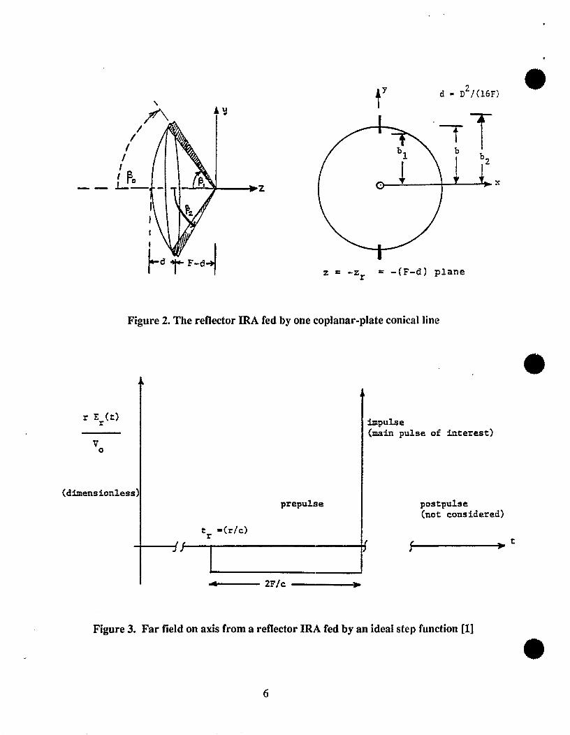
Next, we look at an estimation of boresight waveforms. For analysis purposes, one
could consider a 2 coplanar plate feed (figure 2), although in practice we used 2 such
feed lines connected in parallel for a more uniform illumination of the reflector. When
the reflector IRA was originally proposed [I], the boresight radiation was predicted to
consist of a feed-step followed by an impulse-like behavior as indicated in figure 3. A more
recent analysis [9] has extended the results of figure 3, by chronologically considering the
various temporal elements of the boresight radiation. Let us assume that the voltage pulse
generator is switched on at t = O, and the observer is at a distance r (= z) to the right of
the focal point of the paraboloid. These elements are:
A. Prepulse
1) feed step
B. Main pulse of interest
2) imp&e
C. Postpulse
0 3) feed plate diffraction consisting of two parts
a) plate edge on plate of finite width, large compared to wavelength
b) plate of finite width, small compared to wavelength, modelled by circular
cylinder
4) edge diffraction fkom the circular rim of the paraboloidal reflector
D. Con.9traint8 on entire puhe
5) low-frequency dipole moment radiation and no radiation at zero frequency (de).
All of the above, have been analyzed in the past, but summarized here for completeness.
Prepulse or feed step
This is a direct radiation from source or the “switch” towards the observer. It has a
negative amplitude for the assumed signs of voltages on launcher plates. For the geometry
in figure 2, under the assumption of narrow plates (plate width << plate separation), the
feed step is given by [5],
o where
VOD1%(~, t) = –— — —r 47rfg 2F [‘(’-tr)-u(+++))l (1)
5
●
.—
r Er(t)
\
z
V.
(dimensionless
,
0d= D2/(16F)
z = -Zr = -(F-d) plane
Figure 2. Thereflector IRA fed byone coplanar-plate conical line
prepuhe
r ‘(r/c)-~
impulse(main pulse of titerest)
postpulse(not considered)
Figure3. Far field onaxisfrom arefiector lRAfedby anideal step functional]
6
,
.
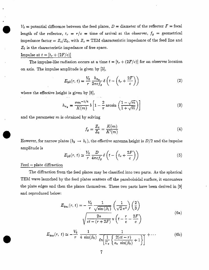
0 V. = potential difference between the feed plates, D = diameter of the reflector F = focal
length of the reflector, t. = r/c = time of arrival at the observer, ~~ = geomeiric~
impedamce factor = ZC/Zo, with ZC = TEM characteristic impedance of the feed line and
ZO is the characteristic impedance of free space.
Impulse at t = [t,+ (2.F/c)]
The impulse-like radiation occurs at a time t = [t. + (217/c)] for an observer location
on axis. The impulse amplitude is given by [5],
9
Ey~(7’,t) = :%(++:))where the effective height is given by [8],
and the parameter m is obtained by solving
K(m)fg = ; = K,(m)
(2)
(3)
(4)
However, for narrow plates (bz ~ bl ), the effective antenna height is D/2 and the impulse
amplitude is
EY2(r, t) m:% ’o-cr+:))
Feed – date diffraction
(5)
The diffraction from the feed plates may be classified into two parts. As the sphericzd
TEM wave launched by the feed plates scatters off the paraboloidal surface, it encounters
the plate edges and then the plates themselves. These two parts have been derived in [9]
and reproduced below:
vi 1Ev~b(r, t) R –—
1
[{
T 4 sin(po) ~n & }12(ct–r) +1 ‘“””
r. a, sin(~o)
(6a)
(6b)
7
.
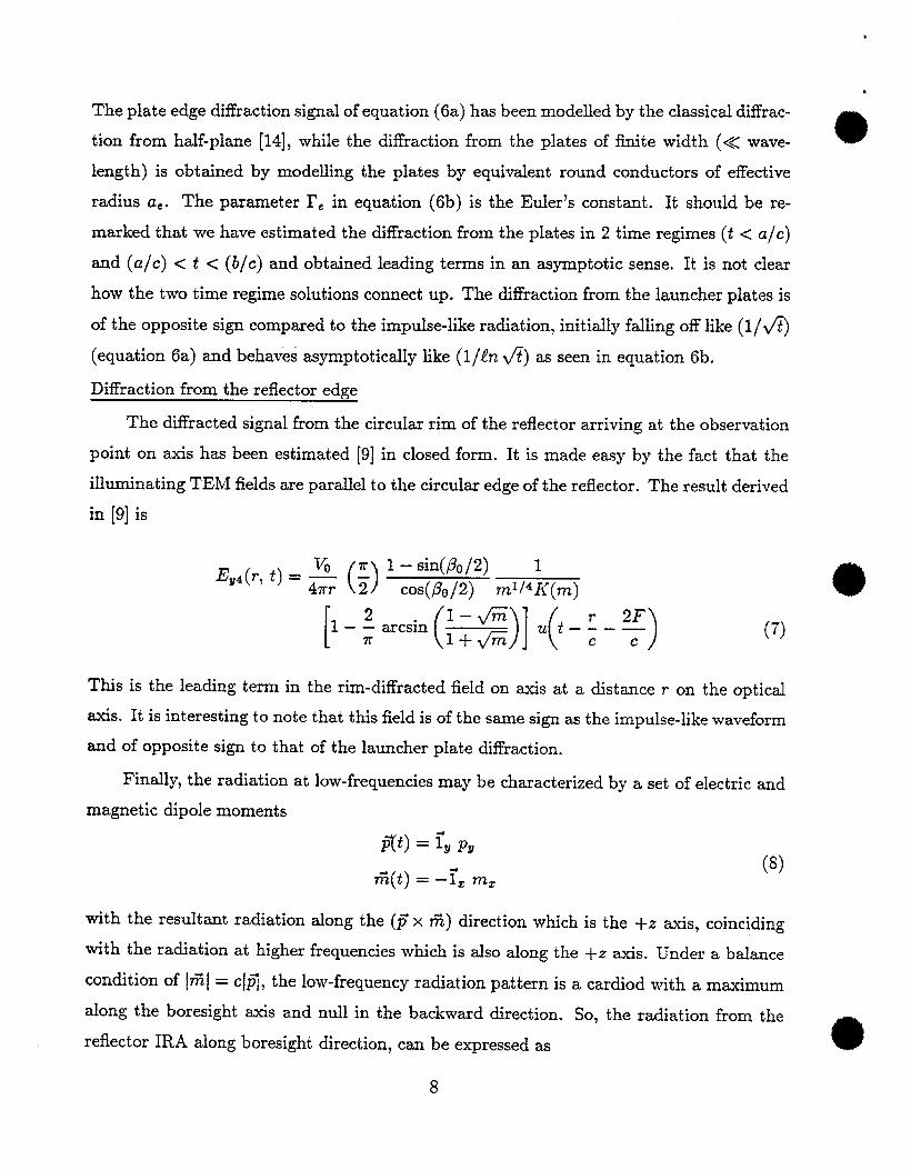
The plate edge diffraction signal of equation (6a) has been modelled by the classiczd diffrac-
tion from half-plane [14], while the d~ffraction from the plates of finite width (<< wave- 0
length) is obtained by modelling the plates by equivalent round conductors of effective
radius a.. The parameter I’. in equation (6b) is the Euler’s constant. It should be re-
marked that we have estimated the diffraction from the plates in 2 time regimes (t < a/c)
and (a/c) < t < (b/c) and obtained leading terms in an asymptotic sense. It is not clear
how the two time regime solutions connect up. The diffraction from the launcher plates is
of the opposite sign compared to the impulse-like radiation, initially falling off like (1/fi)
(equation 6a) and behaves asymptotically like (l//n v’?) as seen in equation 6b.
Diffraction from the reflector edge
The diffracted signal fkom the circular rim of the reflector arriving at the observation
point on axis has been estimated [9] in closed form. It is made easy by the fact that the
illuminating TEM fields are parallel to the circular edge of the reflector. The result derived
in [9] is
vi 7r 1 – sin(~O/2) 1()
Eg~(7’, t)= ~ ~cos(,& /2) n-W4K(?n)
[1 -:mcsincxw-=)
*
(7)
This is the Ieading term in the rim-diffracted field on axis at a distance r on the optical
axis. It is interesting to note that this field is oft he same sign as the impulse-like waveform
and of opposite sign to that of the launcher plate diffraction.
Finally, the radiation at low-frequencies may be characterized by a set of electric and
magnetic dipole moments
(8)
with the resultant
with the radiation
condition of ~RI=
radiation along the (F x W) direction which is the +Z axis, coinciding
at higher frequencies which is also along the +Z axis. Under a balance
c ~fl~the low-frequency radiation pattern is a cardiod with a maximum
along the boresight axis and null in the backward direction.
reflector IRA along boresight direction, can be expressed as
8
So, the radiation from the
@
J?2f(F’,t) = ivq~, q
Ey(r, f) = EY1(7-, t)+ J7y2(~, t)+ qJ3(7’, ~)+ J%4(7’> ~)
+ low-frequency radiation from dipole
moments resulting in time integral
constraints on entire pulse (9)
This result of equation (9) is illustrated in figure 4. The time integral constraints imposed
by the low-frequency radiation are (i) the complete first-time integral of the radiated
waveform must be zero and (ii) the second-time integral must be proportional to the late-
time dipole moments. With this analysis background, we now proceed to describe the
design and performance data.
3. Design Considerations of the Prototype Reflector IRA
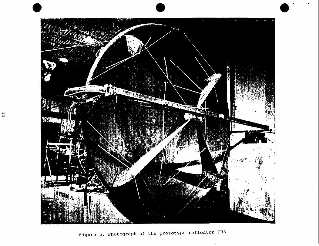
The prototype reflector IRA that has been fabricated and tested is shown in figure
*
5. It consists of a solid-surface, spun-aluminum, paraboloidal reflector of diameter D =
3.66 m, focal length I’ = 1,21 m and ~~ = F/D = 0.33. There are two pairs of coplanar
conical lines, each with a TEM characteristic impedzmce of 400 Q and the corresponding
.f~ = 1.06. The net impedance of the two lines is 200$2. The other geometrical parameters
of the system, with reference to figure 1 are: 6 =’ 1.830 m, 131= 1.585 m, b2 = 2.105 m,
d = depth of the reflector = 0.69 m, /30= 74.29°, PI = 66.58°, @z = 82.30°, and parameter
m= 0.5645.
While the net feed impedance at the feed was designed to be 200 S2by selecting the
proper plate width to separation ratio, the actual fabrication of the terminating impedances ‘
(nominally 2000 at all four junctions between the plates and the reflector rim) needs to
be experimentally optimized. The dc resistance of the termination of each of the two
conical lines equals the TEM characteristic impedance, but the reactive part of the termi-
nating impedances depends on how the series-parallel combination of resistors are assem-
bled. A time-domain reflectometry (TDR) measurement using a TEK-109 (50 V, 180 ps
rise pulse) was performed and the results are shown in figure 6. The initial geometry of
o
the terminator consisted of a high capacitance and lowered voltage stand-off capability.
9

*
b
r Ey(r,t’
prepulse
o2-
impulse
-D/(87rfgF)- : ‘7P~
o1feed step
postpulseb
area= D/(4mcfg)
tr = r\c
ti= tr + (2F\c)
t = ti + (b/c)P
reflector rim c?iffracticn
0
\#
\
?plate diffraction
v’”@plate edge diffraction
Figure4. Onaxisradiation fromacanonical refIectorIRAoffigure2
* * o . .
I-J
Figure 5. Photograph of the prototype reflector IRA

b
*
a)
lut Stoomfk _9*Aalutsit&ru
= st@pp3& mAc4LMtbm .
F : ‘“”’”’”’-”’-’oat”””:’”””:”p””:””””‘:””4. . . . .. . .
I-. . 1.
Iv /
F. . . . . . . . . . . . . . . . . . . . . . ... .,.+.. . . . .
u; =ChlRise -..........
..:?3.4s.,............. ........<..O...........
.1 .4...:: 1;, 1.. ;... ..; ..:.::. :., f....! ‘;:: :::. .::: :::~:::y:
. +. . . .
1;;::. ...:....:....:,,.,
“. . . . . . . . . . . . . . . . . . .
+:::; -. . . . . . . .. . . , . . . . . . . . . . . . . . , , .540ps 9mV
T ; :, i :x— ...
Inpwpulseforthe TDRmeasurement (2Vcharge; -185 psrise)
L. ..- +. ... ‘r. . . . . . . . . . . . . . . . . . . . . . . .& . . . . . . . . . . . . . . . . . . . . . . . .
.-:--+ -----
. . . . . . . . . . . . . . .,.. .
. . . .
. . . .
. . . .
1. . .. . .................... .. .. . .
&...:-..:... . .
lpri.oliw””.””.””””.”,:. 1M ylitiw. - .ls.7ilotis”‘ “ .4T”fy. . . ,..
I&K SCODDf?d: TS6 Acauisithmsx
. --;.—— --—.. ——..—— GL.+____.—$L
.
.
—.>.
—.
‘kI I 50. LM’IW ~ 50. OmV M ?i_~Ons/d 2-a.000ns.
44mf
L. . . .i’”’”a 1 E=
.
b) TDR databefore “trimming” c) TDR data of the optimal terminator
o
Figure 6. TDR measurement for optimizing the terminating impedances
12
*
*
Through a sequence of “trimming” the geometry, we arrived at an optimal termination
geometry. Theaverage power inthe pulse train, when thepulse generator is operated at
200 pulses per second, is of the order of 200 watts. This determined the number of 0.5 watt
series resistors in each of the parallel chains of resistors. At a pulse repetition ffequency
(prf) of 200 Hz, the termination design worked well, but if the prf is upgraded to 1 kHz,
the termination has to be suitably modified.
Next, we turn our attention to the launch region. A uniform dielectric, electromagnetic
lens is included in the launch region to ensure the launching of an approximate spherical
TEM wave onto the conical transmission lines. Inside the lens, we have an exact spherical
TEM wave centered on the switch center. Outside the lens, it is an approximate spherical
TEM wave centered at the focal point of the paraboloidal reflector. The (10–90)% risetime
of the voltage pulse is of the order of 100 ps, which corresponds to a travel time of 3 cm in air
and roughly 2 cm in the oil insulating medium surrounding the “switch” which represents
the source. The switch consists of two conductors in a capsule that has high-pressure
(- 100 atm) hydrogen gas. The switch capsule is surrounded by oil as an insulator, in a
odielectric container. The dielectric constant of the container material is chosen to be same
as that of the oil medium. The oil medium, now serves two
and an electromagnetic lens, which is achieved by shaping
cylindrical coordinate system (Q, z) at the feed is shown in
purposes of voltage standoff
the oil container box. The
figure 7 and the lens design
consists of selecting h = cylindrical radius of the outermost ray and 01~,X = the angle
made by the line inside the lens with respect to the direction of launch. Having selected
these two parameters, we need to find the contour (W/h, z/h) that ensures a spherical
wavefront outside the oil box. The required equations are reproduced below from [15], in
a step-by-step fashion suitable for computations
a) input h= l,& = 2.26, Pzmm = 74.29°, Olmm = 90°
13

terminatlmimpedance.
lensregion..-,..
iIt
I
Y
\
,-- -.
/
a
. -.
I
I
-----paraboloidal
reflector
a) Schematic diagram of the prototype IRA
.-
)
.-
%? WI
lens
\
boundary
—----J-Z4
b) Cylindrical coordinate system (Y, z) at the feed
Figure 7. Geometry for electromagnetic lens design
14

v
& fir [cos(~2mJ+ sin(e2m=)] -1 ~ ~.7626
—=
h (W, - 1) Sin(02m=) –
A = (lz/ll) – 1 = 0.1897
B = (42/41) – tir = –0.3136
c) Next, we vary 61 from O to 90° and compute 62 for each 6$ using [15]
cos(& ) =
Al? sin2(61) + 1? COS(61) – Afir 1/[ 1W–2A13fir cos(@I ) + A2&r – A2 sin2(61)
Bz – 2AB Or COS(61) + AZ &r(12)
d) Then, we find the coordinates of the lens boundary using [15],
(z/h) =tan(ol ) [+ – +] 0.2811 tan(81)
tan(e~) – tan(ez) = tan(o~) – tan(62)
o
(13)
(W/h) = (z/h) tan(@2) = 0“2::(;,~~;:(:;e2)
A simple computer routine is written to carry out the steps and the results are indicated
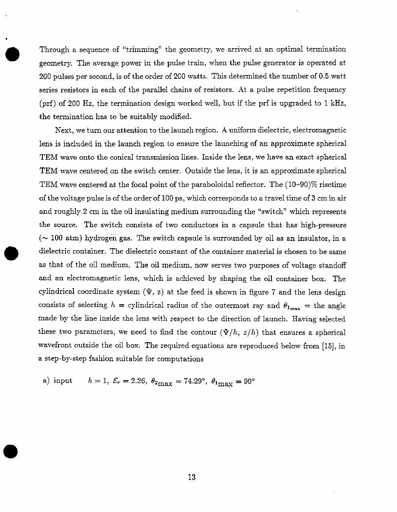
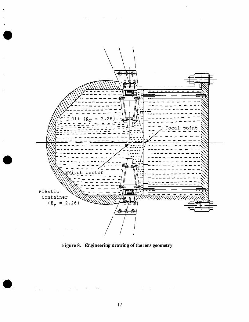
in Table 1. This resulted in the fabrication of the lens, as illustrated in the engineering
drawing of figure 8. This electromagnetic lens has been incorporated into the design of the
pulse generator, which is described in the following section.
4. High-Voltage, Fast Pulse Generator
To maximize the peak far field and its high-frequency content, it was desired to drive
the TEM feed lines with a differential (&V./2) high-voltage and a short risetime. We chose
an approximate exponential decay in the time-domain voltage pulse, so as to get a smooth
radiated spectrum. The e-folding decay time of the voltage pulse was selected to be about
20 ns (large compared to a (l O–9O)% rise) and sufficiently large to radiate signals down to
50 MHz. This lower limit of frequencies radiated by the reflector IRA arises from the physi-
cal size of the reflector (diameter D = 3.66 m), Initially, we set a goal of +50 kV, ~ 150 ps
(10-90)% risetime, N 45 ns (10–90)% fall time, with a prf of 100 Hz. As is seen later,
a we achieved > &60 kV, = 100 ps (10–9O)YOrisetime, w 45 ns (10-90)% fall time and
15

e; 9; z/h @/h
.00 .00 1.7629 .00003.00 2.52 1.7600 .07756.00 5.04 1.7522 .15469.00 7.56 1.7389 .230912.00 10.08 1.7204 .305915.00 12.60 1.6969 .379318.00 15.12 1.6685 .450721.00 17.63 1.6353 .519824.00 20.15 1.5976 .586127.00 22.66 1.5557 .649430.00 25.16 1.5097 .709333,00 27.67 1.4601 .765636.00 30.17 1.4071 .818039.00 32.67 1.3510 .866342.00 35.16 1.2922 .910345.00 37.65 1.2311 ,949948.00 40.14 1.1680 .984951.00 42.62 1.1033 1.015254.00 45.09 1.0374 1.040857.00 47.56 .9707 1.061760.00 50.03 .9035 1.077863.00 52.49 .8362 1.089266.00 54.94 .7691 1.095969.00 57.38 .7027 1.098172.00 59.82 .6373 1.095975.00 62.25 .5731 1.089478.00 64.68 .5105 1.078881.00 67.09 .4498 1.064484.00 69.50 .3912 1.046387.00 71.90 .3349 1.024790.00 74.29 .2812 1.0000
fd = (~/~) = 0.33; %mu = 74.29°; @,mm = 90°
E. = 2.26
TABLE 1. Geometry of the lens boundary surface
16
w
oN&Switch center
F
PlasticContainer
(er = 2. -r I 1
Figure8. Engineering drawing of thelens geometry
17
<
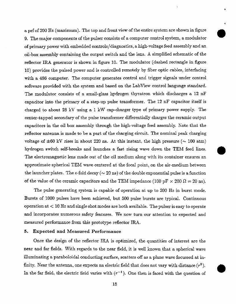
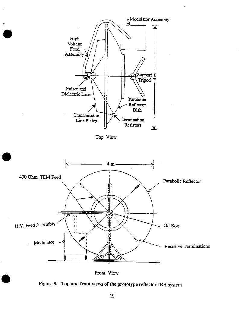
a prf of 200 Hz (maximum). The top and front view of the entire system are shown in figure
9. The major components of the pulser consists of a computer control system, a modulator 0
of primary power with embedded conirols/diagnostics, a high-voltage feed assembly and an
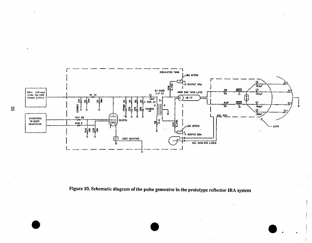
oil-box assembly containing the output switch and the lens. A simplified schematic of the
reflector IRA generator is shown in figure 10. The modulator (dashed rectangle in figure
10) provides the pulsed power and is controlled remotely by fiber optic cables, interfacing
with a 486 computer. The computer generates control and trigger signals under control
software provided with the system and based on the LabView control language standard.
The modulator consists of a small-glass hydrogen thyratron which discharges a 12 nF
capacitor into the primary of a step-up pulse transformer. The 12 nF capacitor itself is
charged to about 28 kV using a 1 kW cap-charger type of primary power supply. The
center-tapped secondary of the pulse transformer differentially charges the ceramic output
capacitors in the oil box assembly through the high-voltage feed assembly. Note that the
reflector antenna is made to be a part of the charging circuit. The nominal peak charging
voltage of +60 kV rises in about 220 ns. At this instant, the high pressure (N 100 atm)
hydrogen switch self-breaks and launches a fast rising wave down the TEM feed lines.0
The electromagnetic lens made out of the oil medium along with its container ensures an
approximate spherical TEM wave centered at the focal point, on the air-medium between
the launcher plates. The e-fold decay (w 20 ns) of the double exponential pulse is a function
of the value of the ceramic capacitors and the TEM impedance (100 pF x 200 Q = 20 ns).
The pulse generating system is capable of operation at up to 200 Hz in burst mode.
Bursts of 1000 pulses have been achieved, but 500 pulse bursts are typical. Continuous
operation at <10 Hz and single shot modes are both available. The pulser is easy to operate
and incorporates numerous safety features. We now turn our attention to expected and
measured performance from this prototype reflector IRA.
5. Expected and Measured Performance
Once the design of the refiector IRA is optimized, the quantities of interest are the
near and far fields. W~th regards to the near field, it is well known that a spherical wave
iIkrninating a paraboloidal conducting surface, scatters off as a plane wave focussed at in-
finity. Near the antenna, one expects an electric field that does not vary with distance (r” ).
In the far field, the electric field varies with (r–l ). One then is faced with the question of *
18
?
Highvoltage
Feed
{
PlllserandDielectric Lens
~Modular.orAssembly
y-
A
‘1TEUlsmi&onLine Plaies
%
Suppm E
Tripd “
ParabolicIk\
/Rdkctor\\\ Dish,-
\ TermimtionRAstoxs
u
Top View
I
400 Ohm TEM Feed
/
H.V. Fed As*mbly
Front View
Parabolic Reflector
Oil Box
Resistive Terminations
Figure 9. Top and front views of the prototype reflector IRA system
19
.—— —— —— —— —— ——-
3@Kv lK)/accMlGt.i vO!. iilGCPOWIR SUPPL7
IMTMIROMlRIGGCf?
GCNCRI31OR
*
I
I
+I
LAl1 !
I
I
1:OIL COOLINO LIN
L ——. — I.—— ——— —. JA
Figure 10. Schematic diagram of the pulse generator in the prototype reflector IRA system
* ~, .