Embed Size (px)
Citation preview
Installation and instruction manual
4-noksElios4you & Elios4you Smart
IT EN FR DE

3
SummaryManuale installazione e istruzioni d’uso ....................................................6
1. Descrizione generale ........................................................................................ 6Contenuto della confezione ............................................................................................................................................. 6Requisiti di compatibilità ................................................................................................................................................. 6Prodotti compatibili con Elios4you ................................................................................................................................... 6Prodotti compatibili con Elios4you Smart ........................................................................................................................ 6
2. Avvertenze di sicurezza .................................................................................... 63. Installazione ..................................................................................................... 6
Prima dell’installazione ................................................................................................................................................... 6Fissaggio e prima accensione ......................................................................................................................................... 6Verifica installazione ....................................................................................................................................................... 7
4. Gestione accessori wireless (solo Elios4you Smart) ........................................ 75. Comportamento LED (tab. 1) ........................................................................... 76. Funzione pulsante (tab. 2) ................................................................................ 77. Significato numeri morsetti (tab. 3) .................................................................. 88. Specifiche tecniche .......................................................................................... 89. Risoluzione problemi ........................................................................................ 910. Conformità ....................................................................................................... 911. Sicurezza e smaltimento .................................................................................. 912. Schemi installazione ...................................................................................... 10
Impianto fotovoltaico collegato al differenziale generale (fig. 2) ..................................................................................... 10Impianto fotovoltaico collegato direttamente al contatore di scambio (fig. 3) ................................................................. 11
Installation and instruction manual ..........................................................121. General description ........................................................................................ 12
Contents of the pack ..................................................................................................................................................... 12Compatibility requirements ........................................................................................................................................... 12Products compatible with Elios4you .............................................................................................................................. 12Products compatible with Elios4you Smart .................................................................................................................... 12
2. Safety warnings ............................................................................................. 123. Installation ...................................................................................................... 12
Prior to installation ........................................................................................................................................................ 12Fixing and first power-up .............................................................................................................................................. 12Check installation ......................................................................................................................................................... 13
4. Management of wireless accessories (Elios4you Smart only) ....................... 135. Response of Leds (table 1) ............................................................................ 136. Operation of button (table 2) .......................................................................... 137. Meaning of terminal numbers (table 3) .......................................................... 148. Technical specifications ................................................................................. 149. Troubleshooting ............................................................................................. 1510. Conformity ..................................................................................................... 1511. Safety and disposal ....................................................................................... 1512. Installation diagrams ...................................................................................... 16
Photovoltaic system connected to main differential switch (fig. 2) ................................................................................. 16Photovoltaic system connected directly to grid meter (fig. 3) ......................................................................................... 17
4
Manuel d’installation et mode d’emploi ...................................................181. Description générale ...................................................................................... 18
Contenu de l’emballage ................................................................................................................................................ 18Conditions de compatibilité ........................................................................................................................................... 18Produits compatibles avec Elios4you............................................................................................................................. 18Produits compatibles avec Elios4you Smart .................................................................................................................. 18
2. Consignes de sécurité ................................................................................... 183. Installation ...................................................................................................... 18
Avant l’installation ........................................................................................................................................................ 18Fixation et premier allumage ......................................................................................................................................... 18Vérification de l’installation ........................................................................................................................................... 19
4. Gestion des accessoires sans fil (uniquement Elios4you Smart) ................... 195. Comportement LED (tableau 1) ..................................................................... 196. Fonction touche (tableau 2) ........................................................................... 197. Signification des numéros de bornes (tableau 3) ........................................... 209. Spécifications techniques .............................................................................. 2010. Résolution des problèmes ............................................................................. 2111. Conformité ..................................................................................................... 2112. Sécurité et élimination .................................................................................... 2113. Schémas d’installation ................................................................................... 22
Installation photovoltaïque connecté au différentiel général (fig. 2) ................................................................................ 22Installation photovoltaïque connectée directement au compteur d’énergie échangée (fig. 3) .......................................... 23
Installations- und Bedienungsanleitung ...................................................241. Allgemeine Beschreibung .............................................................................. 24
Verpackungsinhalt ........................................................................................................................................................ 24Kompatibilitätsanforderungen ....................................................................................................................................... 24Mit Elios4you kompatible Produkte ............................................................................................................................... 24Mit Elios4you Smart kompatible Produkte ..................................................................................................................... 24
2. Sicherheitshinweise ....................................................................................... 243. Installation ...................................................................................................... 24
Vor der Installation ........................................................................................................................................................ 24Befestigung und erstmalige Einschaltung ...................................................................................................................... 25Test der Installation ....................................................................................................................................................... 25
4. Management der drahtlosen Zusatzprodukte (nur Elios4you Smart) ............ 255. LED-Verhalten (Tab. 1) .................................................................................... 256. Tastenfunktion (Tab. 2) ................................................................................... 257. Bedeutung der Klemmennummern (Tab. 3) ................................................... 268. Technische Daten ........................................................................................... 269. Problembehebung .......................................................................................... 2710. Konformität .................................................................................................... 2711. Sicherheit und Entsorgung ............................................................................. 2712. Installationspläne ........................................................................................... 28
Am Hauptfehlerstromschalter angeschlossene PV-Anlage (Abb. 2) ................................................................................ 28Direkt am Zweirichtungszähler angeschlossene PV-Anlage (Abb. 3) .............................................................................. 29
Note / Notes / Notes / Anmerkungen .......................................................30
5
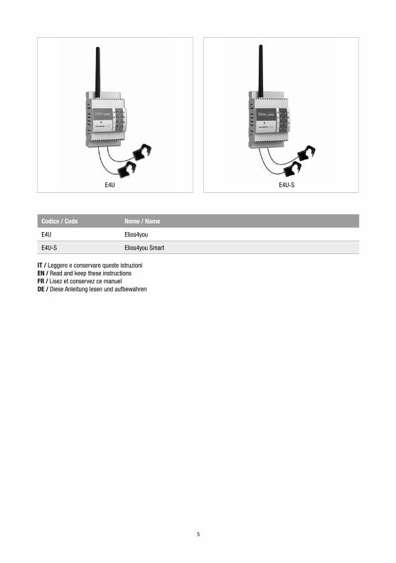
E4U-SE4U
Codice / Code Nome / Name
E4U Elios4you
E4U-S Elios4you Smart
IT / Leggere e conservare queste istruzioniEN / Read and keep these instructionsFR / Lisez et conservez ce manuelDE / Diese Anleitung lesen und aufbewahren
6
IT
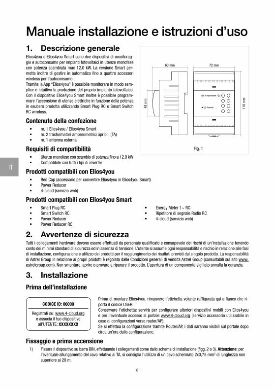
Manuale installazione e istruzioni d’uso1. Descrizione generaleElios4you e Elios4you Smart sono due dispositivi di monitorag-gio e autoconsumo per impianti fotovoltaici in utenze monofase con potenza scambiata max 12.0 kW. La versione Smart per-mette inoltre di gestire in automatico fino a quattro accessori wireless per l’autoconsumo.Tramite la App “Elios4you” è possibile monitorare in modo sem-plice e intuitivo la produzione del proprio impianto fotovoltaico. Con il dispositivo Elios4you Smart inoltre è possibile program-mare l’accensione di utenze elettriche in funzione della potenza in esubero prodotta utilizzando Smart Plug RC e Smart Switch RC wireless.
Contenuto della confezione• nr. 1 Elios4you / Elios4you Smart• nr. 2 trasformatori amperometrici apribili (TA)• nr. 1 antenna esterna
Requisiti di compatibilità• Utenza monofase con scambio di potenza fino a 12.0 kW• Compatibile con tutti i tipi di inverter
Prodotti compatibili con Elios4you• Red Cap (accessorio per convertire Elios4you in Elios4you Smart)• Power Reducer• 4-cloud (servizio web)
Prodotti compatibili con Elios4you Smart• Smart Plug RC• Smart Switch RC• Power Reducer• Power Reducer RC
• Energy Meter 1~ RC• Ripetitore di segnale Radio RC• 4-cloud (servizio web)
2. Avvertenze di sicurezzaTutti i collegamenti hardware devono essere effettuati da personale qualificato e consapevole dei rischi di un’installazione tenendo conto dei minimi standard di sicurezza ed in assenza di tensione. L’utente si assume ogni responsabilità e rischio in relazione alle fasi di installazione, configurazione e utilizzo dei prodotti per il raggiungimento dei risultati previsti dal singolo prodotto. La responsabilità di Astrel Group in relazione ai propri prodotti è regolata dalle Condizioni generali di vendita Astrel Group (consultabili sul sito www.astrelgroup.com). Non smontare, aprire o provare a riparare il prodotto. L’apertura di un componente sigillato annulla la garanzia.
3. InstallazionePrima dell’installazione
CODICE ID: 00000
Registrati su: www.4-cloud.orge associa il tuo dispositivoall’UTENTE: XXXXXXXX
Prima di montare Elios4you, rimuovere l’etichetta volante raffigurata qui a fianco che ri-porta il codice USER. Conservare l’etichetta: servirà per configurare ulteriori dispositivi mobili con Elios4you e per l’eventuale accesso al portale www.4-cloud.org (servizio accessorio utilizzabile in caso di configurazioni verso router/AP). Se si effettua la configurazione tramite Router/AP, i dati saranno visibili sul portale dopo circa un’ora dalla configurazione.
Fissaggio e prima accensione1) Fissare il dispositivo su barra DIN, effettuando i collegamenti come dallo schema di installazione (figg. 2 o 3). Attenzione: per
l’eventuale allungamento del cavo relativo ai TA, si consiglia l’utilizzo di un cavo schermato 2x0,75 mm2 di lunghezza non superiore ai 20 m.
110
mm
72 mm60 mm
45 m
m
LED di segnalazione
Pulsante
Fig. 1
7
IT
ATTENZIONE: assicurarsi che tra i 2 TA e i contatori relativi non ci siano ulteriori utenze collegate. In caso contrario le misurazioni non sarebbero corrette.
2) Dopo avere installato e alimentato il dispositivo, installare l’App gratuita “Elios4you” su tablet o smartphone scaricandola da App Store o Google Play Store
3) Lanciare l’App “Elios4you” ed effettuare la configurazione guidata come da procedura disponibile su www.4-noks.com/tutorial4) Solo per dispositivo Elios4you Smart: accedere al Menu Smart RC premere sul pulsante “Abilita” per
attivare la funzione Smart RC (Radio Control)5) Settare i parametri corretti dell’impianto fotovoltaico e dell’utenza elettrica domestica via App: Menu “Impostazioni
impianto” selezionare “Parametri, costi e incentivi” e impostare i valori desiderati premere OK una volta completata l’operazione.
6) Per maggiori informazioni visitare la pagina www.4-noks.com/tutorial
Verifica installazione7) Verificare nella pagina la veridicità dei dati:
− Premere l’icona “Home” per tornare alla pagina “Attività impianto” − Assicurarsi che il valore della potenza prodotta “Produzione” corrisponda con quella letta dall’inverter − Valutare che il valore “Consumo” corrisponda ai consumi istantanei di potenza dell’utenza monitorata
ATTENZIONE: quando Elios4you è configurato per l’accesso a internet (tramite Router/AP), lo storico dati viene inviato anche al portale 4-cloud. Collegarsi al sito www.4-cloud.org e seguire le istruzioni per la registrazione. Utilizzare il codice USER riportato in etichetta per l’associazione del dispositivo.
4. Gestione accessori wireless (solo Elios4you Smart)Tramite la App “Elios4you” è possibile programmare l’accensione di utenze elettriche in funzione dell’energia in esubero prodotta utilizzando accessori radio per l’autoconsumo. Per gli accessori Smart RC al dispositivo Elios4you Smart si faccia riferimento ai rispettivi manuali di installazione ed uso.
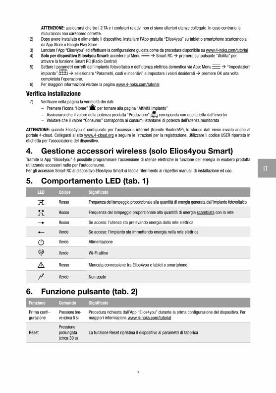
5. Comportamento LED (tab. 1)LED Colore Significato
Rosso Frequenza del lampeggio proporzionale alla quantità di energia generata dall’impianto fotovoltaico
Rosso Frequenza del lampeggio proporzionale alla quantità di energia scambiata con la rete
Rosso Se acceso: l’utenza sta prelevando energia dalla rete elettrica
Verde Se acceso: l’impianto sta immettendo energia nella rete elettrica
Verde Alimentazione
Verde Wi-Fi attivo
Rosso Mancata connessione tra Elios4you e tablet o smartphone
Verde Non usato
6. Funzione pulsante (tab. 2)Funzione Comando Significato
Prima confi-gurazione
Pressione bre-ve (circa 6 s)
Procedura richiesta dall’App “Elios4you” durante la prima configurazione del dispositivo. Per maggiori informazioni: www.4-noks.com/tutorial
ResetPressione prolungata(circa 30 s)
La funzione Reset ripristina il dispositivo ai parametri di fabbrica
8
IT
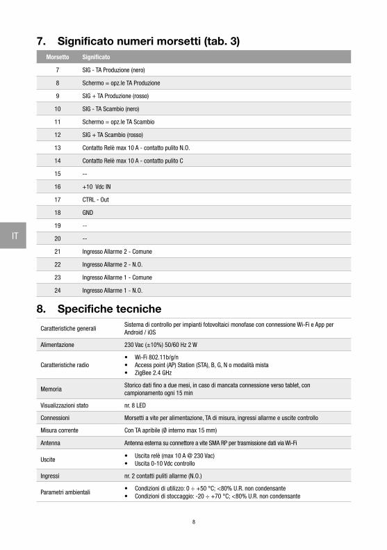
7. Significato numeri morsetti (tab. 3)Morsetto Significato
7 SIG - TA Produzione (nero)
8 Schermo = opz.le TA Produzione
9 SIG + TA Produzione (rosso)
10 SIG - TA Scambio (nero)
11 Schermo = opz.le TA Scambio
12 SIG + TA Scambio (rosso)
13 Contatto Relè max 10 A - contatto pulito N.O.
14 Contatto Relè max 10 A - contatto pulito C
15 --
16 +10 Vdc IN
17 CTRL - Out
18 GND
19 --
20 --
21 Ingresso Allarme 2 - Comune
22 Ingresso Allarme 2 - N.O.
23 Ingresso Allarme 1 - Comune
24 Ingresso Allarme 1 - N.O.
8. Specifiche tecniche
Caratteristiche generaliSistema di controllo per impianti fotovoltaici monofase con connessione Wi-Fi e App per Android / iOS
Alimentazione 230 Vac (±10%) 50/60 Hz 2 W
Caratteristiche radio• Wi-Fi 802.11b/g/n• Access point (AP) Station (STA), B, G, N o modalità mista • ZigBee 2.4 GHz
MemoriaStorico dati fino a due mesi, in caso di mancata connessione verso tablet, con campionamento ogni 15 min
Visualizzazioni stato nr. 8 LED
Connessioni Morsetti a vite per alimentazione, TA di misura, ingressi allarme e uscite controllo
Misura corrente Con TA apribile (Ø interno max 15 mm)
Antenna Antenna esterna su connettore a vite SMA RP per trasmissione dati via Wi-Fi
Uscite• Uscita relè (max 10 A @ 230 Vac)• Uscita 0-10 Vdc controllo
Ingressi nr. 2 contatti puliti allarme (N.O.)
Parametri ambientali• Condizioni di utilizzo: 0 ÷ +50 °C; <80% U.R. non condensante• Condizioni di stoccaggio: -20 ÷ +70 °C; <80% U.R. non condensante
9
IT
Grado di protezione IP20
Dimensioni (L x H x P) Contenitore da guida DIN 4 moduli 72 x 110 x 60 mm
9. Risoluzione problemi1) Nella schermata principale non vedo mai la potenza prodotta dall’impianto fotovoltaico
• Eseguire la rotazione del TA di produzione (etichetta bianca) portando il pallino verde o la freccia all’interno del TA nel verso opposto a quello attualmente utilizzato.
• Accertarsi che all’interno della pinza passi solamente il cavo di fase dell’impianto: l’eventuale passaggio al suo interno sia della fase che del neutro genera un errore.
• Assicurarsi che il TA internamente non si sia rotto durante l’installazione: il nucleo interno non deve avere crepe o pezzi mancanti.
2) La potenza prodotta visualizzata nell’App è di molto inferiore a quella letta dall’inverter• Accertarsi che l’alimentazione di Elios4you sia stata presa dalla stessa linea elettrica in cui sono posizionate le due pinze
amperometriche.• Accertarsi della corretta e totale chiusura del TA di produzione (etichetta bianca): il TA deve essere in grado di pinzare il
cavo senza problemi, sono quindi da evitare forti pressioni per permetterne la chiusura.
3) Il consumo rilevato segue l’andamento della potenza prodotta• Accertarsi che il TA di scambio (etichetta gialla) sia posizionato sull’intero fascio di fasi in uscita dal contatore Enel come
da schema, probabilmente rileva i dati del cavo in cui passano i soli consumi dell’utenza.• Accertarsi che all’interno dei due TA passi solamente il cavo di fase dell’impianto: l’eventuale passaggio al suo interno sia
della fase che del neutro genera un errore.• Assicurarsi che i due TA non riportino internamente segni evidenti di rotture.
4) Il consumo dell’utenza sembra essere rilevato nell’icona di rete elettrica• Accertarsi che il TA di scambio (etichetta gialla) sia posizionato sull’intero fascio di fasi in uscita dal contatore Enel come
da schema, probabilmente rileva i dati del cavo in cui passano i soli consumi dell’utenza.
5) Non vedo mai immissioni di potenza in rete sul mio impianto• Accertarsi che il TA di scambio (etichetta gialla) sia posizionato sull’intero fascio di fasi in uscita dal contatore Enel come
da schema, probabilmente rileva i dati del cavo in cui passano i soli consumi dell’utenza.
6) Durante la notte il consumo è nullo, mentre durante il giorno è sempre più alto del normale• Eseguire la rotazione del TA di scambio (etichetta gialla) portando il pallino verde o la freccia all’interno del TA nel verso
opposto a quello attualmente utilizzato.
7) Nell’App vedo consumi molto elevati, mentre l’utenza sta consumando pochissimo• Eseguire la rotazione del TA di scambio (etichetta gialla) portando il pallino verde o la freccia all’interno del TA nel verso
opposto a quello attualmente utilizzato. • Accertarsi che il TA di scambio (etichetta gialla) sia posizionato sull’intero fascio di fasi in uscita dal contatore come da
schema, probabilmente rileva i dati del cavo in cui passano i soli consumi dell’utenza.
10. ConformitàCon la presente Astrel Group dichiara che questo prodotto è conforme ai requisiti essenziali ed alle disposizioni pertinenti stabilite dalla direttiva 2014/53/UE (RED). La dichiarazione di conformità può essere consultata sul sito www.astrelgroup.com.
11. Sicurezza e smaltimentoApparecchiatura elettrica ed elettronica oggetto di raccolta separata, in conformità alle vigenti normative locali in materia di smaltimento.
Astrel Group si riserva il diritto di modificare le caratteristiche dei prodotti senza preavviso.
10
IT
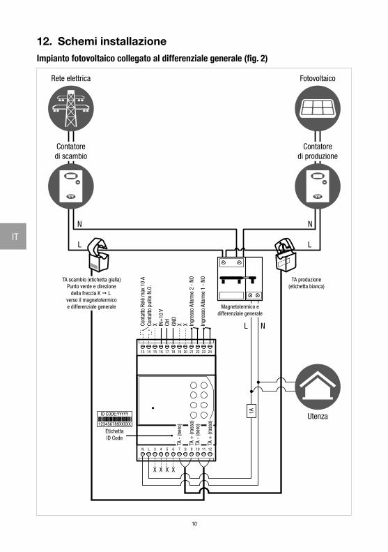
12. Schemi installazioneImpianto fotovoltaico collegato al differenziale generale (fig. 2)
13 14 15 16 17 18 19 20 21 22 23 24
1211109876543LN
1A
TA produzione(etichetta bianca)
Contatoredi scambio
Rete elettrica
Contatoredi produzione
Fotovoltaico
TA scambio (etichetta gialla)Punto verde e direzione
della freccia K L verso il magnetotermicoe differenziale generale
Utenza
Magnetotermico edifferenziale generale
Ingr
esso
Alla
rme
2 -
NO
Ingr
esso
Alla
rme
1 -
NO
IN+
10 V
Ctrl
GND
Cont
atto
Rel
è m
ax 1
0 A
Cont
atto
pul
ito N
.O.
X X X
ID CODE:YYYYY
123456789XXXXX
EtichettaID Code
X X X X
L
N
L
N
L N
TA -
(ner
o)
TA -
(ner
o)TA
+ (r
osso
)
TA +
(ros
so)
11
IT
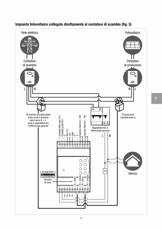
Impianto fotovoltaico collegato direttamente al contatore di scambio (fig. 3)
13 14 15 16 17 18 19 20 21 22 23 24
1211109876543LN
1A
TA -
(ner
o)
TA -
(ner
o)TA
+ (r
osso
)
TA +
(ros
so)
Rete elettrica
Contatoredi scambio
Contatoredi produzione
Fotovoltaico
Ingr
esso
Alla
rme
2 -
NO
Ingr
esso
Alla
rme
1 -
NO
IN+
10 V
Ctrl
GND
Cont
atto
Rel
è m
ax 1
0 A
Cont
atto
pul
ito N
.O.
X X X
TA produzione(etichetta bianca)
Magnetotermico edifferenziale generale
L N
TA scambio (etichetta gialla)Punto verde e direzione
della freccia K L verso il magnetotermicoe differenziale generale
UtenzaID CODE:YYYYY
123456789XXXXX
EtichettaID Code
X X X X
LNL N
12
EN
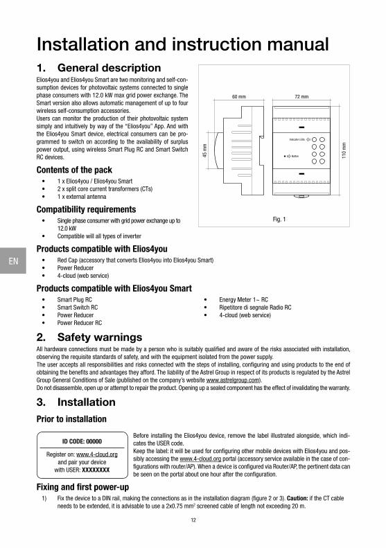
Installation and instruction manual1. General descriptionElios4you and Elios4you Smart are two monitoring and self-con-sumption devices for photovoltaic systems connected to single phase consumers with 12.0 kW max grid power exchange. The Smart version also allows automatic management of up to four wireless self-consumption accessories.Users can monitor the production of their photovoltaic system simply and intuitively by way of the “Elios4you” App. And with the Elios4you Smart device, electrical consumers can be pro-grammed to switch on according to the availability of surplus power output, using wireless Smart Plug RC and Smart Switch RC devices.
Contents of the pack• 1 x Elios4you / Elios4you Smart• 2 x split core current transformers (CTs)• 1 x external antenna
Compatibility requirements• Single phase consumer with grid power exchange up to
12.0 kW• Compatible will all types of inverter
Products compatible with Elios4you• Red Cap (accessory that converts Elios4you into Elios4you Smart)• Power Reducer• 4-cloud (web service)
Products compatible with Elios4you Smart• Smart Plug RC• Smart Switch RC• Power Reducer• Power Reducer RC
• Energy Meter 1~ RC• Ripetitore di segnale Radio RC• 4-cloud (web service)
2. Safety warningsAll hardware connections must be made by a person who is suitably qualified and aware of the risks associated with installation, observing the requisite standards of safety, and with the equipment isolated from the power supply. The user accepts all responsibilities and risks connected with the steps of installing, configuring and using products to the end of obtaining the benefits and advantages they afford. The liability of the Astrel Group in respect of its products is regulated by the Astrel Group General Conditions of Sale (published on the company’s website www.astrelgroup.com).Do not disassemble, open up or attempt to repair the product. Opening up a sealed component has the effect of invalidating the warranty.
3. InstallationPrior to installation
ID CODE: 00000
Register on: www.4-cloud.organd pair your device
with USER: XXXXXXXX
Before installing the Elios4you device, remove the label illustrated alongside, which indi-cates the USER code. Keep the label: it will be used for configuring other mobile devices with Elios4you and pos-sibly accessing the www.4-cloud.org portal (accessory service available in the case of con-figurations with router/AP). When a device is configured via Router/AP, the pertinent data can be seen on the portal about one hour after the configuration.
Fixing and first power-up1) Fix the device to a DIN rail, making the connections as in the installation diagram (figure 2 or 3). Caution: if the CT cable
needs to be extended, it is advisable to use a 2x0.75 mm2 screened cable of length not exceeding 20 m.
110
mm
72 mm60 mm
45 m
m
Indicator LEDs
Button
Fig. 1
13
EN
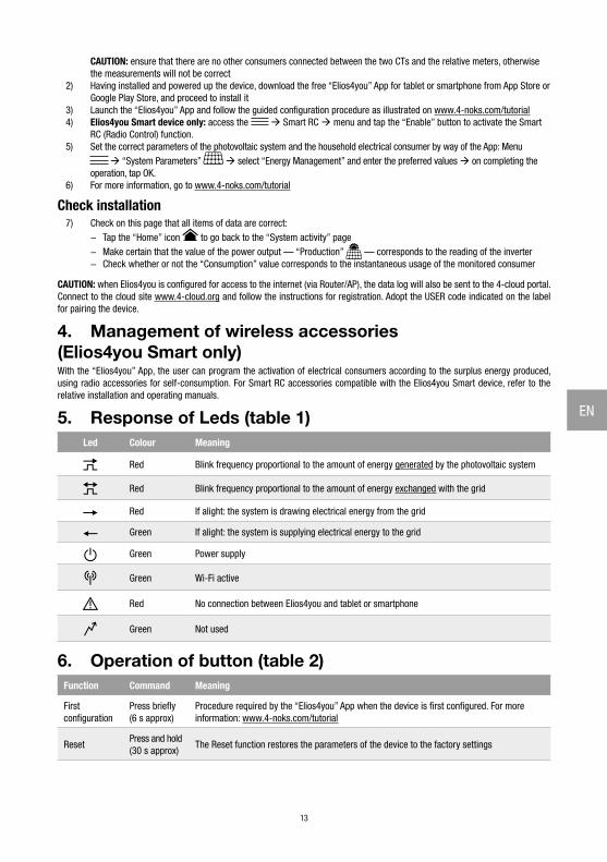
CAUTION: ensure that there are no other consumers connected between the two CTs and the relative meters, otherwise the measurements will not be correct
2) Having installed and powered up the device, download the free “Elios4you” App for tablet or smartphone from App Store or Google Play Store, and proceed to install it
3) Launch the “Elios4you” App and follow the guided configuration procedure as illustrated on www.4-noks.com/tutorial4) Elios4you Smart device only: access the Smart RC menu and tap the “Enable” button to activate the Smart
RC (Radio Control) function.5) Set the correct parameters of the photovoltaic system and the household electrical consumer by way of the App: Menu
“System Parameters” select “Energy Management” and enter the preferred values on completing the operation, tap OK.
6) For more information, go to www.4-noks.com/tutorial
Check installation7) Check on this page that all items of data are correct:
− Tap the “Home” icon to go back to the “System activity” page − Make certain that the value of the power output — “Production” — corresponds to the reading of the inverter − Check whether or not the “Consumption” value corresponds to the instantaneous usage of the monitored consumer
CAUTION: when Elios4you is configured for access to the internet (via Router/AP), the data log will also be sent to the 4-cloud portal. Connect to the cloud site www.4-cloud.org and follow the instructions for registration. Adopt the USER code indicated on the label for pairing the device.
4. Management of wireless accessories (Elios4you Smart only)With the “Elios4you” App, the user can program the activation of electrical consumers according to the surplus energy produced, using radio accessories for self-consumption. For Smart RC accessories compatible with the Elios4you Smart device, refer to the relative installation and operating manuals.
5. Response of Leds (table 1)Led Colour Meaning
Red Blink frequency proportional to the amount of energy generated by the photovoltaic system
Red Blink frequency proportional to the amount of energy exchanged with the grid
Red If alight: the system is drawing electrical energy from the grid
Green If alight: the system is supplying electrical energy to the grid
Green Power supply
Green Wi-Fi active
Red No connection between Elios4you and tablet or smartphone
Green Not used
6. Operation of button (table 2)Function Command Meaning
First configuration
Press briefly(6 s approx)
Procedure required by the “Elios4you” App when the device is first configured. For more information: www.4-noks.com/tutorial
ResetPress and hold (30 s approx)
The Reset function restores the parameters of the device to the factory settings
14
EN
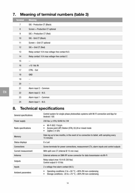
7. Meaning of terminal numbers (table 3)Terminal Meaning
7 SIG - Production CT (Black)
8 Screen = Production CT optional
9 SIG + Production CT (Red)
10 SIG - Grid CT (Black)
11 Screen = Grid CT optional
12 SIG + Grid CT (Red)
13 Relay contact 10 A max voltage-free contact N.O.
14 Relay contact 10 A max voltage-free contact C
15 --
16 +10 Vdc IN
17 CTRL - Out
18 GND
19 --
20 --
21 Alarm input 2 - Common
22 Alarm input 2 - N.O.
23 Alarm input 1 - Common
24 Alarm input 1 - N.O.
8. Technical specifications
General specificationsControl system for single-phase photovoltaic systems with Wi-Fi connection and App for Android / iOS
Power supply 230 Vac (±10%) 50/60 Hz 2 W
Radio specifications• Wi-Fi 802.11b/g/n• Access point (AP) Station (STA), B,G,N or mixed mode • ZigBee 2.4 GHz
MemoryData log up to two months, in the event of no connection to tablet, with sampling every 15 minutes
Status displays 8 x Led
Connections Screw terminals for power connections, measurement CTs, alarm inputs and control outputs
Current measurement With split core CT (internal Ø 15 mm max)
Antenna External antenna on SMA RP screw connector for data transmission via Wi-Fi
OutputsRelay output (max 10 A @ 230 Vac)Control output 0-10 Vdc
Inputs 2 x voltage-free alarm contact (N.O.)
Ambient parameters• Operating conditions: 0 to +50 °C; <80% RH non-condensing• Storage conditions: -20 to +70 °C; <80% RH non-condensing
15
EN
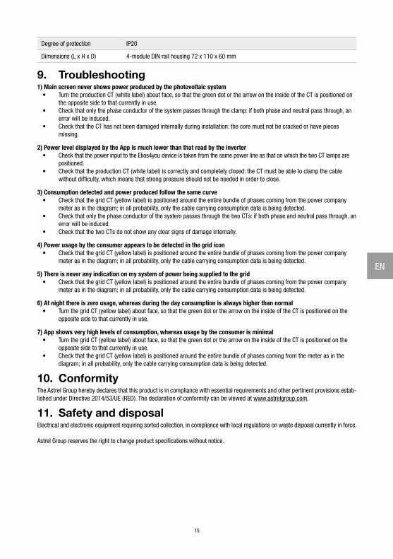
Degree of protection IP20
Dimensions (L x H x D) 4-module DIN rail housing 72 x 110 x 60 mm
9. Troubleshooting1) Main screen never shows power produced by the photovoltaic system
• Turn the production CT (white label) about face, so that the green dot or the arrow on the inside of the CT is positioned on the opposite side to that currently in use.
• Check that only the phase conductor of the system passes through the clamp: if both phase and neutral pass through, an error will be induced.
• Check that the CT has not been damaged internally during installation: the core must not be cracked or have pieces missing.
2) Power level displayed by the App is much lower than that read by the inverter• Check that the power input to the Elios4you device is taken from the same power line as that on which the two CT lamps are
positioned.• Check that the production CT (white label) is correctly and completely closed: the CT must be able to clamp the cable
without difficulty, which means that strong pressure should not be needed in order to close.
3) Consumption detected and power produced follow the same curve• Check that the grid CT (yellow label) is positioned around the entire bundle of phases coming from the power company
meter as in the diagram; in all probability, only the cable carrying consumption data is being detected.• Check that only the phase conductor of the system passes through the two CTs: if both phase and neutral pass through, an
error will be induced.• Check that the two CTs do not show any clear signs of damage internally.
4) Power usage by the consumer appears to be detected in the grid icon• Check that the grid CT (yellow label) is positioned around the entire bundle of phases coming from the power company
meter as in the diagram; in all probability, only the cable carrying consumption data is being detected.
5) There is never any indication on my system of power being supplied to the grid• Check that the grid CT (yellow label) is positioned around the entire bundle of phases coming from the power company
meter as in the diagram; in all probability, only the cable carrying consumption data is being detected.
6) At night there is zero usage, whereas during the day consumption is always higher than normal• Turn the grid CT (yellow label) about face, so that the green dot or the arrow on the inside of the CT is positioned on the
opposite side to that currently in use.
7) App shows very high levels of consumption, whereas usage by the consumer is minimal• Turn the grid CT (yellow label) about face, so that the green dot or the arrow on the inside of the CT is positioned on the
opposite side to that currently in use. • Check that the grid CT (yellow label) is positioned around the entire bundle of phases coming from the meter as in the
diagram; in all probability, only the cable carrying consumption data is being detected.
10. ConformityThe Astrel Group hereby declares that this product is in compliance with essential requirements and other pertinent provisions estab-lished under Directive 2014/53/UE (RED). The declaration of conformity can be viewed at www.astrelgroup.com.
11. Safety and disposalElectrical and electronic equipment requiring sorted collection, in compliance with local regulations on waste disposal currently in force.
Astrel Group reserves the right to change product specifications without notice.
16
EN
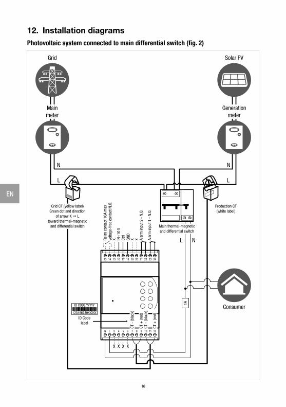
12. Installation diagramsPhotovoltaic system connected to main differential switch (fig. 2)
13 14 15 16 17 18 19 20 21 22 23 24
1211109876543LN
1A
Production CT(white label)
Mainmeter
Grid
Generationmeter
Solar PV
Grid CT (yellow label)Green dot and direction
of arrow K Ltoward thermal-magnetic
and differential switch
Consumer
Main thermal-magneticand differential switch
Alar
m in
put 2
- N
.O.
Alar
m in
put 1
- N
.O.
IN+
10 V
Ctrl
GND
Rela
y co
ntac
t 10A
max
volta
ge-f
ree
cont
act N
.O.
X X X
ID CODE:YYYYY
123456789XXXXX
ID Codelabel
X X X X
L
N
L
N
L N
CT -
(bla
ck)
CT -
(bla
ck)
CT +
(red
)
CT +
(red
)
17
EN
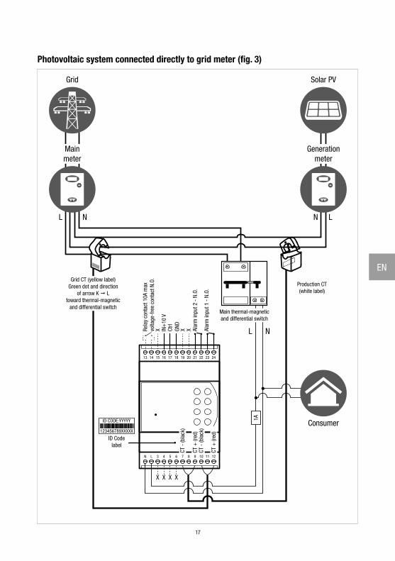
Photovoltaic system connected directly to grid meter (fig. 3)
13 14 15 16 17 18 19 20 21 22 23 24
1211109876543LN
1A
CT -
(bla
ck)
CT -
(bla
ck)
CT +
(red
)
CT +
(red
)
IN+
10 V
Ctrl
GND
X X X L N
ID CODE:YYYYY
123456789XXXXX
ID Codelabel
X X X X
LNL N
Production CT(white label)
Mainmeter
Grid
Generationmeter
Solar PV
Grid CT (yellow label)Green dot and direction
of arrow K Ltoward thermal-magnetic
and differential switch
Consumer
Main thermal-magneticand differential switch
Alar
m in
put 2
- N
.O.
Alar
m in
put 1
- N
.O.
Rela
y co
ntac
t 10A
max
volta
ge-f
ree
cont
act N
.O.
18
FR
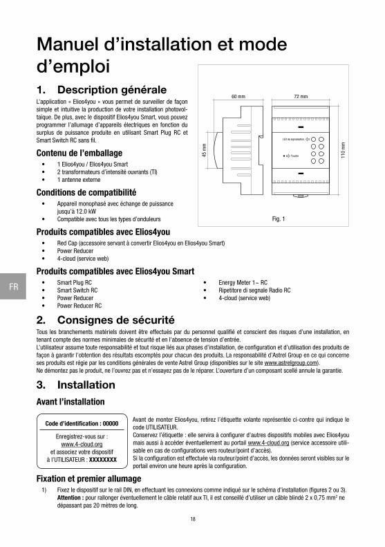
Manuel d’installation et mode d’emploi1. Description généraleL’application « Elios4you » vous permet de surveiller de façon simple et intuitive la production de votre installation photovol-taïque. De plus, avec le dispositif Elios4you Smart, vous pouvez programmer l’allumage d’appareils électriques en fonction du surplus de puissance produite en utilisant Smart Plug RC et Smart Switch RC sans fil.
Contenu de l’emballage• 1 Elios4you / Elios4you Smart• 2 transformateurs d’intensité ouvrants (TI)• 1 antenne externe
Conditions de compatibilité• Appareil monophasé avec échange de puissance
jusqu’à 12.0 kW• Compatible avec tous les types d’onduleurs
Produits compatibles avec Elios4you• Red Cap (accessoire servant à convertir Elios4you en Elios4you Smart)• Power Reducer• 4-cloud (service web)
Produits compatibles avec Elios4you Smart• Smart Plug RC• Smart Switch RC• Power Reducer• Power Reducer RC
• Energy Meter 1~ RC• Ripetitore di segnale Radio RC• 4-cloud (service web)
2. Consignes de sécuritéTous les branchements matériels doivent être effectués par du personnel qualifié et conscient des risques d’une installation, en tenant compte des normes minimales de sécurité et en l’absence de tension d’entrée. L’utilisateur assume toute responsabilité et tout risque liés aux phases d’installation, de configuration et d’utilisation des produits de façon à garantir l’obtention des résultats escomptés pour chacun des produits. La responsabilité d’Astrel Group en ce qui concerne ses produits est régie par les conditions générales de vente Astrel Group (disponibles sur le site www.astrelgroup.com).Ne démontez pas le produit, ne l’ouvrez pas et n’essayez pas de le réparer. L’ouverture d’un composant scellé annule la garantie.
3. InstallationAvant l’installation
Code d’identification : 00000
Enregistrez-vous sur :www.4-cloud.org
et associez votre dispositifà l’UTILISATEUR : XXXXXXXX
Avant de monter Elios4you, retirez l’étiquette volante représentée ci-contre qui indique le code UTILISATEUR. Conservez l’étiquette : elle servira à configurer d’autres dispositifs mobiles avec Elios4you mais aussi à accéder éventuellement au portail www.4-cloud.org (service accessoire utili-sable en cas de configurations vers routeur/point d’accès). Si la configuration est effectuée via routeur/point d’accès, les données seront visibles sur le portail environ une heure après la configuration.
Fixation et premier allumage1) Fixez le dispositif sur le rail DIN, en effectuant les connexions comme indiqué sur le schéma d’installation (figures 2 ou 3).
Attention : pour rallonger éventuellement le câble relatif aux TI, il est conseillé d’utiliser un câble blindé 2 x 0,75 mm2 ne dépassant pas 20 mètres de long.
110
mm
72 mm60 mm
45 m
m
LED de signalisation
Touche
Fig. 1
19
FR
ATTENTION : assurez-vous qu’aucun autre appareil n’est branché entre les 2 TI et les contacteurs correspondants. Dans le cas contraire, les mesures seraient incorrectes.
2) Après avoir installé et alimenté le dispositif, installez l’application gratuite « Elios4you » sur tablette ou smartphone en la téléchargeant sur l’App Store ou Google Play Store
3) Lancez l’application « Elios4you » et suivez l’assistant de configuration comme l’indique la procédure disponible sur www.4-noks.com/tutorial
4) Uniquement pour le dispositif Elios4you Smart : accédez au menu Smart RC et appuyez sur la touche « Activer » pour activer la fonction Smart RC (Radio Control)
5) Configurez les bons paramètres de l’installation photovoltaïque et de l’appareil électrique domestique via l’appli : Menu « Paramètres Système » Sélectionnez « Gestion de l’ènergie » et réglez les valeurs souhaitées
appuyez sur OK une fois l’opération terminée.6) Pour plus d’informations, visitez la page www.4-noks.com/tutorial
Vérification de l’installation7) Vérifiez l’exactitude des données sur la page :
− Appuyez sur l’icône « Accueil » pour revenir à la page « Activité installation » − Assurez-vous que la valeur de la puissance produite « Production » correspond à celle lue par l’onduleur − Déterminer si la valeur de « Consommation » correspond à la consommation instantanée de puissance de l’appareil contrôlé
ATTENTION : Lorsque Elios4you est configuré pour l’accès à Internet (via un routeur/point d’accès), l’historique des données est également envoyé vers le portail 4-cloud. Connectez-vous au site www.4-cloud.org et suivez les instructions pour l’enregistrement. Utilisez le code UTILISATEUR figurant sur l’étiquette pour le couplage du dispositif.
4. Gestion des accessoires sans fil (uniquement Elios4you Smart)Via l’application « Elios4you », vous pouvez programmer l’allumage des appareils électriques en fonction du surplus d’énergie pro-duite, en utilisant des accessoires radio pour l’autoconsommation. Pour les accessoires Smart RC au dispositif Elios4you Smart, référez-vous aux manuels d’installation et modes d’emploi correspondants.
5. Comportement LED (tableau 1)LED Couleur Signification
RougeFréquence de clignotement proportionnelle à la quantité d’énergie générée par l’installation photovoltaïque
Rouge Fréquence de clignotement proportionnelle à la quantité d’énergie échangée avec le réseau
Rouge Allumée : l’appareil puise de l’énergie sur le réseau électrique
Vert Allumée : l’appareil injecte de l’énergie dans le réseau électrique
Vert Alimentation
Vert Wi-Fi actif
Rouge Échec de connexion entre Elios4you et la tablette ou le smartphone
Vert Non utilisé
6. Fonction touche (tableau 2)Fonction Commande Signification
Première configuration
Pression brève (env 6 s)
Procédure requise par l’application « Elios4you » lors de la première configuration du dispositif. Pour plus d’informations : www.4-noks.com/tutorial
RéinitialisationPression prolongée (env 30 s)
La fonction Réinitialisation rétablit les paramètres d’usine du dispositif
20
FR
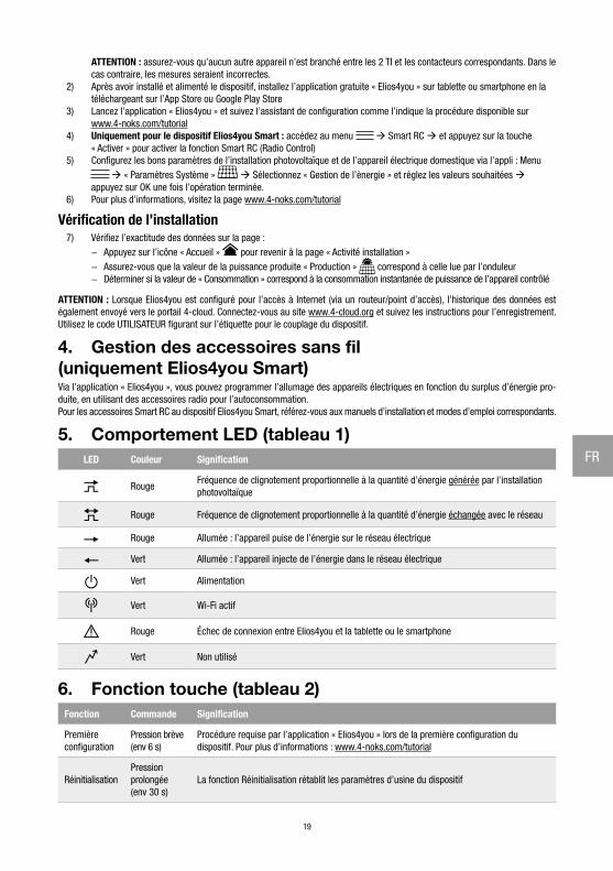
7. Signification des numéros de bornes (tableau 3)Borne Signification
7 SIG - TI production (noir)
8 Blindage = opz. TI production
9 SIG + TI production (rouge)
10 SIG - TI échange (noir)
11 Blindage = opz. TI échange
12 SIG + TI échange (rouge)
13 Contact relais max 10 A - contact sec N.O.
14 Contact relais max 10 A - contact sec C
15 --
16 +10 Vdc IN
17 CTRL - Out
18 GND
19 --
20 --
21 Entrée alarme 2 - Commun
22 Entrée alarme 2 - N.O.
23 Entrée alarme 1 - Commun
24 Entrée alarme 1 - N.O.
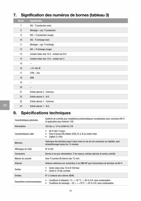
9. Spécifications techniques
Caractéristiques généralesSystème de contrôle pour installations photovoltaïques monophasées avec connexion Wi-Fi et application pour Android / iOS
Alimentation 230 Vac (± 10 %) 50/60 Hz 2 W
Caractéristiques radio• Wi-Fi 802.11b/g/n• Point d’accès (PA) Station (STA), B, G, N ou mode mixte • ZigBee 2.4 GHz
MémoireHistorique des données jusqu’à deux mois en cas de non connexion sur tablette, avec échantillonnage toutes les 15 minutes
Affichages de l’état N° 8 LED
Connexions Bornes à vis pour alimentation, TI de mesure, entrées alarmes et sorties contrôle
Mesure du courant Avec TI ouvrant (Ø interne max 15 mm)
Antenne Antenne extérieure sur connecteur à vis SMA RP pour transmission de données via Wi-Fi
Sorties• Sortie relais (max 10 A @ 230 Vac)• Sortie 0-10 Vdc contrôle
Entrées N° 2 contacts secs alarme (NON)
Paramètres environnementaux• Conditions d’utilisation : 0 ÷ + 50 °C ; < 80 % H.R. sans condensation• Conditions de stockage : -20 ÷ + +70°C ; < 80 % H.R. sans condensation
21
FR
Degré de protection IP20
Dimensions (L x H x P) Boîtier rail DIN 4 modules 72 x 110 x 60 mm
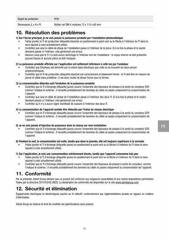
10. Résolution des problèmes1) Sur l’écran principal, je ne vois jamais la puissance produite par l’installation photovoltaïque
• Faites pivoter le TI de production (étiquette blanche) en positionnant le point vert ou la flèche à l’intérieur du TI dans le sens opposé à celui actuellement utilisé.
• Contrôlez que seul le câble de phase de l’installation passe à l’intérieur de la pince. Si à la fois la phase et le neutre devaient passer à l’intérieur, cela génèrerait une erreur.
• Assurez-vous que le TI n’a subi aucun dommage à l’intérieur lors de l’installation : le noyau interne ne doit présenter aucune fissure et aucune pièce ne doit manquer.
2) La puissance produite affichée sur l’application est nettement inférieure à celle lue par l’onduleur• Contrôlez que Elios4you est alimenté par la même ligne électrique que celle où se trouvent les deux pinces
ampèremétriques.• Contrôlez que le TI de production (étiquette blanche) est correctement et totalement fermé : le TI doit être en mesure de
pincer le câble sans problème ; il est donc inutile de devoir forcer pour le fermer.
3) La consommation détectée suit l’évolution de la puissance produite• Contrôlez que le TI d’échange (étiquette jaune) couvre l’ensemble des faisceaux de phases à la sortie du compteur EDF,
comme l’indique le schéma ; il recueille probablement les données du câble où passe uniquement la consommation de l’appareil.
• Contrôlez que seul le câble de phase de l’installation passe à l’intérieur des deux TI. Si à la fois la phase et le neutre devaient passer à l’intérieur, cela génèrerait une erreur.
• Contrôlez qu’il n’y a aucun signe manifeste de cassure à l’intérieur des deux TI.
4) La consommation de l’appareil semble être détectée par l’icône du réseau électrique• Contrôlez que le TI d’échange (étiquette jaune) couvre l’ensemble des faisceaux de phases à la sortie du compteur EDF,
comme l’indique le schéma ; il recueille probablement les données du câble où passe uniquement la consommation de l’appareil.
5) Je ne vois jamais d’injection de puissance dans le réseau sur mon installation• Contrôlez que le TI d’échange (étiquette jaune) couvre l’ensemble des faisceaux de phases à la sortie du compteur EDF,
comme l’indique le schéma ; il recueille probablement les données du câble où passe uniquement la consommation de l’appareil.
6) Pendant la nuit, la consommation est nulle, tandis que dans la journée, elle est toujours supérieure à la normale• Faites pivoter le TI d’échange (étiquette jaune) en positionnant le point vert ou la flèche à l’intérieur du TI dans le sens
opposé à celui actuellement utilisé.
7) Sur l’application, je vois une consommation extrêmement élevée, tandis que l’appareil consomme très peu• Faites pivoter le TI d’échange (étiquette jaune) en positionnant le point vert ou la flèche à l’intérieur du TI dans le sens
opposé à celui actuellement utilisé. • Contrôlez que le TI d’échange (étiquette jaune) couvre l’ensemble des faisceaux de phases à sortie du compteur, comme
l’indique le schéma ; il recueille probablement les données du câble où passe uniquement la consommation de l’appareil.
11. ConformitéPar la présente, Astrel Group déclare que ce produit est conforme aux exigences essentielles et aux autres dispositions pertinentes fixées par la directive 2014/53/UE (RED). La déclaration de conformité est disponible sur le site www.astrelgroup.com.
12. Sécurité et éliminationÉquipements électriques et électroniques soumis au tri sélectif, conformément aux réglementations locales en vigueur en matière d’élimination.
Astrel Group se réserve le droit de modifier les spécifications sans préavis.
22
FR
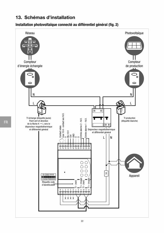
13. Schémas d’installationInstallation photovoltaïque connecté au différentiel général (fig. 2)
13 14 15 16 17 18 19 20 21 22 23 24
1211109876543LN
1A
TI production(étiquette blanche)
Compteurd’énergie échangée
Réseau
Compteurde production
Photovoltaïque
TI échange (étiquette jaune)Point vert et direction
de la flèche K L vers ledisjoncteur magnétothermique
et différentiel général
Appareil
Disjoncteur magnétothermiqueet différentiel général
Entré
e al
arm
e 2
- N.
O.
Entré
e al
arm
e 1
- N.
O.
IN+
10 V
Ctrl
GND
Cont
act r
elai
sm
ax 1
0 A
- co
ntac
t sec
N.O
.X X X
ID CODE:YYYYY
123456789XXXXX
Étiquette coded’identification
X X X X
L
N
L
N
L N
TI -
(noi
r)
TI -
(noi
r)TI
+ (r
ouge
)
TI +
(rou
ge)
23
FR
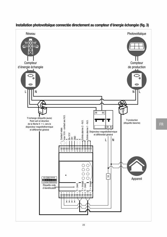
Installation photovoltaïque connectée directement au compteur d’énergie échangée (fig. 3)
13 14 15 16 17 18 19 20 21 22 23 24
1211109876543LN
1A
IN+
10 V
Ctrl
GND
X X X L N
ID CODE:YYYYY
123456789XXXXX
X X X X
LNL N
TI production(étiquette blanche)
Compteurd’énergie échangée
Réseau
Compteurde production
Photovoltaïque
TI échange (étiquette jaune)Point vert et direction
de la flèche K L vers ledisjoncteur magnétothermique
et différentiel général
Appareil
Disjoncteur magnétothermiqueet différentiel général
Entré
e al
arm
e 2
- N.
O.
Entré
e al
arm
e 1
- N.
O.
Cont
act r
elai
sm
ax 1
0 A
- co
ntac
t sec
N.O
.
Étiquette coded’identification
TI -
(noi
r)
TI -
(noi
r)TI
+ (r
ouge
)
TI +
(rou
ge)
24
DE
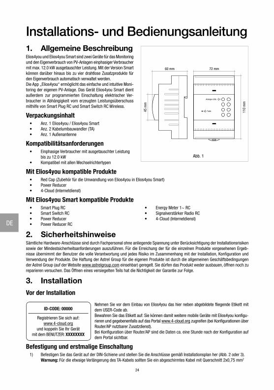
Installations- und Bedienungsanleitung1. Allgemeine BeschreibungElios4you und Elios4you Smart sind zwei Geräte für das Monitoring und den Eigenverbrauch von PV-Anlagen einphasiger Verbraucher mit max. 12.0 kW ausgetauschter Leistung. Mit der Version Smart können darüber hinaus bis zu vier drahtlose Zusatzprodukte für den Eigenverbrauch automatisch verwaltet werden.Die App „Elios4you“ ermöglicht das einfache und intuitive Moni-toring der eigenen PV-Anlage. Das Gerät Elios4you Smart dient außerdem zur programmierten Einschaltung elektrischer Ver-braucher in Abhängigkeit vom erzeugten Leistungsüberschuss mithilfe von Smart Plug RC und Smart Switch RC Wireless.
Verpackungsinhalt• Anz. 1 Elios4you / Elios4you Smart• Anz. 2 Kabelumbauwandler (TA)• Anz. 1 Außenantenne
Kompatibilitätsanforderungen• Einphasige Verbraucher mit ausgetauschter Leistung
bis zu 12.0 kW• Kompatibel mit allen Wechselrichtertypen
Mit Elios4you kompatible Produkte• Red Cap (Zubehör für die Umwandlung von Elios4you in Elios4you Smart)• Power Reducer• 4-Cloud (Internetdienst)
Mit Elios4you Smart kompatible Produkte• Smart Plug RC• Smart Switch RC• Power Reducer• Power Reducer RC
• Energy Meter 1~ RC• Signalverstärker Radio RC• 4-Cloud (Internetdienst)
2. SicherheitshinweiseSämtliche Hardware-Anschlüsse sind durch Fachpersonal ohne anliegende Spannung unter Berücksichtigung der Installationsrisiken sowie der Mindestsicherheitsanforderungen auszuführen. Für die Erreichung der für die einzelnen Produkte vorgesehenen Ergeb-nisse übernimmt der Benutzer die volle Verantwortung und jedes Risiko im Zusammenhang mit der Installation, Konfiguration und Verwendung der Produkte. Die Haftung der Astrel Group für die eigenen Produkte ist durch die allgemeinen Geschäftsbedingungen der Astrel Group (auf der Website www.astrelgroup.com einsehbar) geregelt. Sie dürfen das Produkt weder ausbauen, öffnen noch zu reparieren versuchen. Das Öffnen eines versiegelten Teils hat die Nichtigkeit der Garantie zur Folge.
3. InstallationVor der Installation
ID-CODE: 00000
Registrieren Sie sich auf: www.4-cloud.org
und koppeln Sie Ihr Gerätmit dem BENUTZER: XXXXXXXX
Nehmen Sie vor dem Einbau von Elios4you das hier neben abgebildete fliegende Etikett mit dem USER-Code ab. Bewahren Sie das Etikett auf: Sie können damit weitere mobile Geräte mit Elios4you konfigu-rieren und gegebenenfalls auf das Portal www.4-cloud.org zugreifen (bei Konfigurationen über Router/AP nutzbarer Zusatzdienst). Bei Konfiguration über Router/AP sind die Daten ca. eine Stunde nach der Konfiguration auf dem Portal sichtbar.
Befestigung und erstmalige Einschaltung1) Befestigen Sie das Gerät auf der DIN-Schiene und stellen Sie die Anschlüsse gemäß Installationsplan her (Abb. 2 oder 3).
Warnung: Für die etwaige Verlängerung des TA-Kabels sollten Sie ein abgeschirmtes Kabel mit Querschnitt 2x0,75 mm2
110
mm
72 mm60 mm
45 m
m
Anzeige-LEDs
Taste
Abb. 1
25
DE
und 20 m maximaler Länge verwenden. WARNUNG: Stellen Sie sicher, dass zwischen den 2 TA und den jeweiligen Zählern keine weiteren Verbraucher angeschlossen sind. Die Messungen werden ansonsten verfälscht.
2) Downloaden Sie nach Installation und Netzanschluss des Geräts die kostenlose App „Elios4you“ aus dem App Store oder Google Play Store und installieren Sie diese auf Tablet oder Smartphone
3) Starten Sie die App „Elios4you“ und führen Sie den Konfigurationsassistenten gemäß den Anleitungen auf www.4-noks.com/tutorial aus4) Nur für das Gerät Elios4you Smart: rufen Sie das Menü Smart RC auf und klicken Sie auf die Taste
„Aktivieren“, um die Funktion Smart RC (Radio Control) zu aktivieren5) Stellen Sie die korrekten Parameter der PV-Anlage und den Haushalts-Stromverbraucher anhand der App ein: Menü
„System Parameter“ wählen Sie „Energiemanagement“ und stellen Sie die gewünschten Werte ein klicken Sie auf OK nach Abschluss des Vorgangs.
6) Für weitere Informationen besuchen Sie die Seite www.4-noks.com/tutorial
Test der Installation7) Überprüfen Sie auf der Seite die Richtigkeit der Daten:
− Klicken Sie auf das Symbol „Home“ , um zur Seite „Anlagenbetrieb“zurückzukehren − Vergewissern Sie sich, dass der Wert der erzeugten Leistung „Erzeugung“ dem vom Wechselrichter abgelesenen entspricht − Prüfen Sie, ob der Wert „Verbrauch“ dem momentanen Leistungsverbrauch des überwachten Verbrauchers entspricht
WARNUNG: Bei Konfiguration von Elios4you für die Internetverbindung (über Router/AP) wird der Datenverlauf auch an das Portal 4-Cloud gesendet. Rufen Sie die Website www.4-cloud.org auf und befolgen Sie die Anleitungen zur Registrierung. Verwenden Sie den USER-Code auf dem Etikett für die Kopplung des Geräts.
4. Management der drahtlosen Zusatzprodukte (nur Elios4you Smart)Über die App „Elios4you“ können Sie die Einschaltung elektrischer Verbraucher in Abhängigkeit vom erzeugten Energieüberschuss mithilfe der Funk-Zusatzprodukte für den Eigenverbrauch programmieren. Für die Zusatzprodukte Smart RC zum Gerät Elios4you Smart wird auf die entsprechenden Installations- und Bedienungsanleitungen verwiesen.
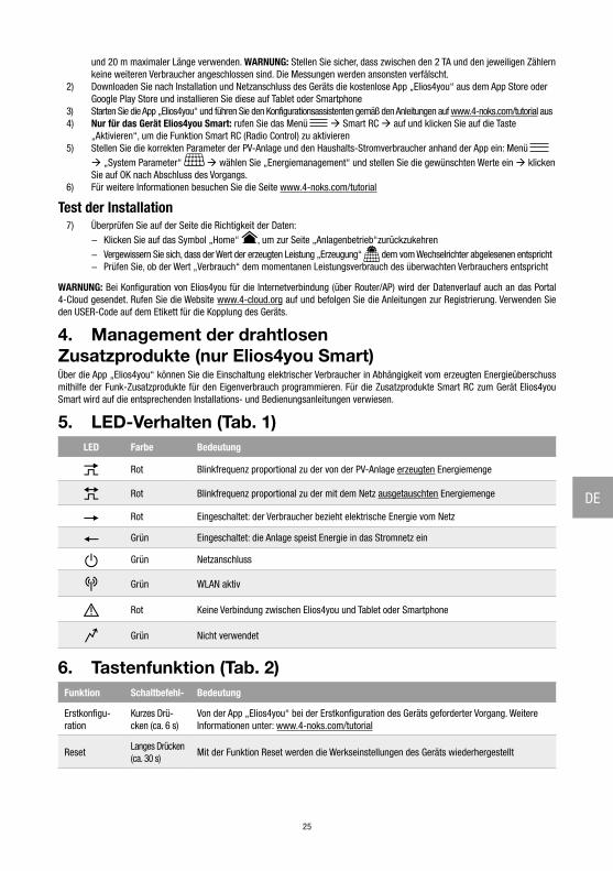
5. LED-Verhalten (Tab. 1)LED Farbe Bedeutung
Rot Blinkfrequenz proportional zu der von der PV-Anlage erzeugten Energiemenge
Rot Blinkfrequenz proportional zu der mit dem Netz ausgetauschten Energiemenge
Rot Eingeschaltet: der Verbraucher bezieht elektrische Energie vom Netz
Grün Eingeschaltet: die Anlage speist Energie in das Stromnetz ein
Grün Netzanschluss
Grün WLAN aktiv
Rot Keine Verbindung zwischen Elios4you und Tablet oder Smartphone
Grün Nicht verwendet
6. Tastenfunktion (Tab. 2)Funktion Schaltbefehl- Bedeutung
Erstkonfigu-ration
Kurzes Drü-cken (ca. 6 s)
Von der App „Elios4you“ bei der Erstkonfiguration des Geräts geforderter Vorgang. Weitere Informationen unter: www.4-noks.com/tutorial
ResetLanges Drücken (ca. 30 s)
Mit der Funktion Reset werden die Werkseinstellungen des Geräts wiederhergestellt
26
DE
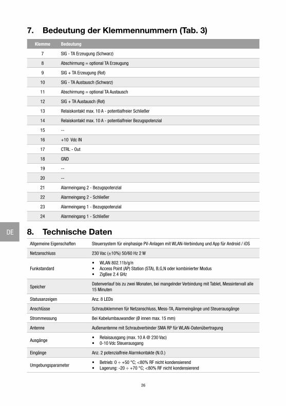
7. Bedeutung der Klemmennummern (Tab. 3)
Klemme Bedeutung
7 SIG - TA Erzeugung (Schwarz)
8 Abschirmung = optional TA Erzeugung
9 SIG + TA Erzeugung (Rot)
10 SIG - TA Austausch (Schwarz)
11 Abschirmung = optional TA Austausch
12 SIG + TA Austausch (Rot)
13 Relaiskontakt max. 10 A - potentialfreier Schließer
14 Relaiskontakt max. 10 A - potentialfreier Bezugspotenzial
15 --
16 +10 Vdc IN
17 CTRL - Out
18 GND
19 --
20 --
21 Alarmeingang 2 - Bezugspotenzial
22 Alarmeingang 2 - Schließer
23 Alarmeingang 1 - Bezugspotenzial
24 Alarmeingang 1 - Schließer
8. Technische DatenAllgemeine Eigenschaften Steuersystem für einphasige PV-Anlagen mit WLAN-Verbindung und App für Android / iOS
Netzanschluss 230 Vac (±10%) 50/60 Hz 2 W
Funkstandard• WLAN 802.11b/g/n• Access Point (AP) Station (STA), B,G,N oder kombinierter Modus• ZigBee 2.4 GHz
SpeicherDatenverlauf bis zu zwei Monaten, bei mangelnder Verbindung mit Tablet, Messintervall alle 15 Minuten
Statusanzeigen Anz. 8 LEDs
Anschlüsse Schraubklemmen für Netzanschluss, Mess-TA, Alarmeingänge und Steuerausgänge
Strommessung Bei Kabelumbauwandler (Ø innen max. 15 mm)
Antenne Außenantenne mit Schraubverbinder SMA RP für WLAN-Datenübertragung
Ausgänge• Relaisausgang (max. 10 A @ 230 Vac)• 0-10 Vdc Steuerausgang
Eingänge Anz. 2 potenzialfreie Alarmkontakte (N.O.)
Umgebungsparameter• Betrieb: 0 ÷ +50 °C; <80% RF nicht kondensierend• Lagerung: -20 ÷ +70 °C; <80% RF nicht kondensierend
27
DE
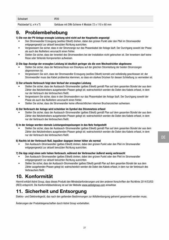
Schutzart IP20
Platzbedarf (L x H x T) Gehäuse mit DIN-Schiene 4 Module 72 x 110 x 60 mm
9. Problembehebung1) Die von der PV-Anlage erzeugte Leistung wird nicht auf der Hauptseite angezeigt
• Den Stromwandler Erzeugung (weißes Etikett) drehen, dabei den grünen Punkt oder den Pfeil im Stromwandler entgegengesetzt zur aktuell benutzten Richtung ausrichten.
• Vergewissern Sie sicher, dass in der Stromzange nur das Phasenkabel der Anlage läuft. Der Durchgang sowohl der Phase als auch des Nullleiters verursacht einen Fehler.
• Stellen Sie sicher, dass der Innenteil des Stromwandlers bei der Installation nicht gebrochen ist. Der Innenkern darf keine Risse oder fehlende Komponenten aufweisen.
2) Die App-Anzeige der erzeugten Leistung ist deutlich geringer als die vom Wechselrichter abgelesene• Stellen Sie sicher, dass der Netzanschluss von Elios4you auf der gleichen Stromleitung der beiden Stromzangen
abgenommen ist.• Vergewissern Sie sich, dass der Stromwandler Erzeugung (weißes Etikett) korrekt und vollständig geschlossen ist: der
Stromwandler muss das Kabel problemlos klemmen, so dass ein starkes Drücken für dessen Schließung zu vermeiden ist.
3) Der erfasste Verbrauch folgt dem Verlauf der erzeugten Leistung• Stellen Sie sicher, dass der Austausch-Stromwandler (gelbes Etikett) gemäß Plan auf dem gesamten Bündel der aus dem
Zähler des Netzbetreibers ausgehenden Phasen gelegt ist; wahrscheinlich werden die Daten des Kabels erfasst, in dem nur der Verbrauch des Verbrauchers fließt.
• Vergewissern Sie sicher, dass in den Stromwandlern nur das Phasenkabel der Anlage läuft. Der Durchgang sowohl der Phase als auch des Nullleiters verursacht einen Fehler.
• Stellen Sie sicher, dass die Stromwandler keine offensichtlichen internen Bruchanzeichen aufweisen.
4) Der Verbrauch der Anlage wird scheinbar im Symbol des Stromnetzes erfasst• Stellen Sie sicher, dass der Austausch-Stromwandler (gelbes Etikett) gemäß Plan auf dem gesamten Bündel der aus dem
Zähler des Netzbetreibers ausgehenden Phasen gelegt ist; wahrscheinlich werden die Daten des Kabels erfasst, in dem nur der Verbrauch des Verbrauchers fließt.
5) In der Anlage werden niemals Leistungseinspeisungen in das Netz festgestellt• Stellen Sie sicher, dass der Austausch-Stromwandler (gelbes Etikett) gemäß Plan auf dem gesamten Bündel der aus dem
Zähler des Netzbetreibers ausgehenden Phasen gelegt ist; wahrscheinlich werden die Daten des Kabels erfasst, in dem nur der Verbrauch des Verbrauchers fließt.
6) Nachts ist der Verbrauch Null, tagsüber dagegen immer höher als normal• Den Austausch-Stromwandler (gelbes Etikett) drehen, dabei den grünen Punkt oder den Pfeil im Stromwandler
entgegengesetzt zur aktuell benutzten Richtung ausrichten.
7) Die App zeigt einen sehr hohen Verbrauch, während der Verbraucher äußerst wenig verbraucht• Den Austausch-Stromwandler (gelbes Etikett) drehen, dabei den grünen Punkt oder den Pfeil im Stromwandler
entgegengesetzt zur aktuell benutzten Richtung ausrichten. • Stellen Sie sicher, dass der Austausch-Stromwandler (gelbes Etikett) gemäß Plan auf dem gesamten Bündel der aus dem
Zähler ausgehenden Phasen gelegt ist; wahrscheinlich werden die Daten des Kabels erfasst, in dem nur der Verbrauch des Verbrauchers fließt.
10. KonformitätHiermit erklärt Astrel Group, dass dieses Produkt den Mindestanforderungen und den anderen Vorschriften der Richtlinie 2014/53/EG (RED) entspricht. Die Konformitätserklärung ist auf der Website www.astrelgroup.com einsehbar.
11. Sicherheit und EntsorgungElektro- und Elektronikgerät, das nach den geltenden Bestimmungen zur Abfallentsorgung getrennt gesammelt werden muss.
Änderungen der Produkteigenschaften durch Astrel Group vorbehalten.
28
DE
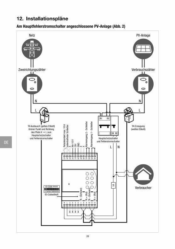
12. InstallationspläneAm Hauptfehlerstromschalter angeschlossene PV-Anlage (Abb. 2)
13 14 15 16 17 18 19 20 21 22 23 24
1211109876543LN
1A
TA Erzeugung(weißes Etikett)
Zweirichtungszähler
Netz
Verbrauchszähler
PV-Anlage
TA Austausch (gelbes Etikett)Grüner Punkt und Richtung
des Pfeils K L zumHauptschutzschalter
und Fehlerstromschalter
Verbraucher
Hauptschutzschalterund Fehlerstromschalter
Alar
mei
ngan
g 2
- Sc
hlie
ßer
Alar
mei
ngan
g 1
- Sc
hlie
ßer
IN+
10 V
Ctrl
GND
Rela
isko
ntak
t max
. 10
Apo
tent
ialfr
eier
Sch
ließe
rX X X
ID CODE:YYYYY
123456789XXXXX
ID-Codeetikett
X X X X
L
N
L
N
L N
TA -
(Sch
war
z)
TA -
(Sch
war
z)TA
+ (R
ot)
TA +
(Rot
)
29
DE
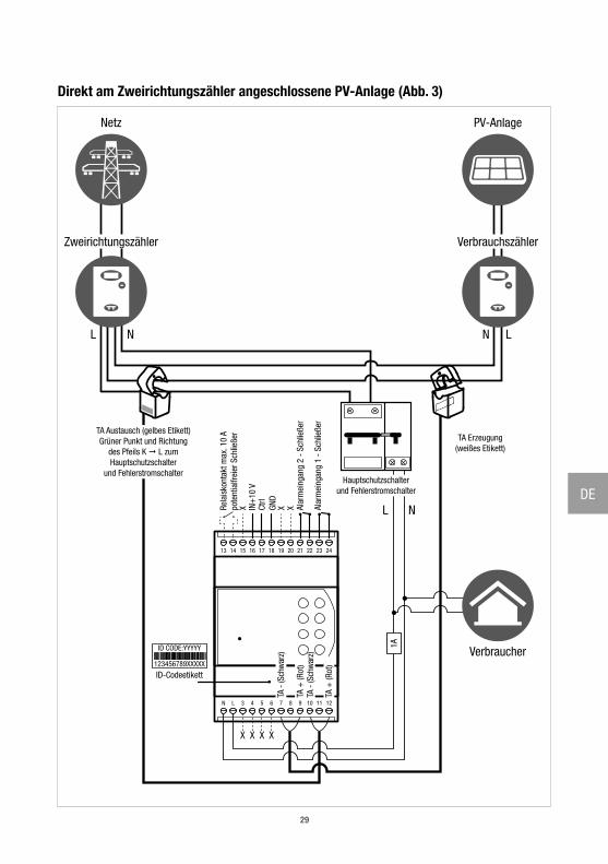
Direkt am Zweirichtungszähler angeschlossene PV-Anlage (Abb. 3)
13 14 15 16 17 18 19 20 21 22 23 24
1211109876543LN
1A
IN+
10 V
Ctrl
GND
X X X L N
ID CODE:YYYYY
123456789XXXXX
X X X X
LNL N
TA Erzeugung(weißes Etikett)
Zweirichtungszähler
Netz
Verbrauchszähler
PV-Anlage
TA Austausch (gelbes Etikett)Grüner Punkt und Richtung
des Pfeils K L zumHauptschutzschalter
und Fehlerstromschalter
Verbraucher
Hauptschutzschalterund Fehlerstromschalter
Alar
mei
ngan
g 2
- Sc
hlie
ßer
Alar
mei
ngan
g 1
- Sc
hlie
ßer
Rela
isko
ntak
t max
. 10
Apo
tent
ialfr
eier
Sch
ließe
r
ID-Codeetikett
TA -
(Sch
war
z)
TA -
(Sch
war
z)TA
+ (R
ot)
TA +
(Rot
)
30
Note / Notes / Notes / Anmerkungen

4-NOKS is a brand of ASTREL GROUPASTREL GROUP SRLVia Isonzo, 21/E / 34070 Mossa (GO) Italywww.astrelgroup.com / www.4-noks.com
+05T408030R3.0 Elios4you & Elios4you Smart Instruction manual_IT-EN-FR-DE 2019.05.28