Embed Size (px)
Citation preview
1 Copyright © 2010, Everlight All Rights Reserved. Release Date: Sep 1, 2016. Issue No: DPC-0000116 Rev.6 www.everlight.com
4 PIN SOP PHOTOTRANSISTOR PHOTOCOUPLER
AC INPUT PHOTOCOUPLE EL354N-G Series
Features
• Halogens free (Br <900 ppm ,Cl <900 ppm , Br+Cl < 1500 ppm)
• Current transfer ratio (CTR: Min. 20% at IF =±1mA ,VCE =5V) • High isolation voltage between input and output (Viso=3750 V rms) • Compact small outline package • Compliance with EU REACH • The product itself will remain within RoHS compliant version • Compliance with EU REACH • UL and cUL approved (No. E214129) • VDE approved (No. 132249) • SEMKO approved • NEMKO approved • DEMKO approved • FIMKO approved • CQC approved
Description
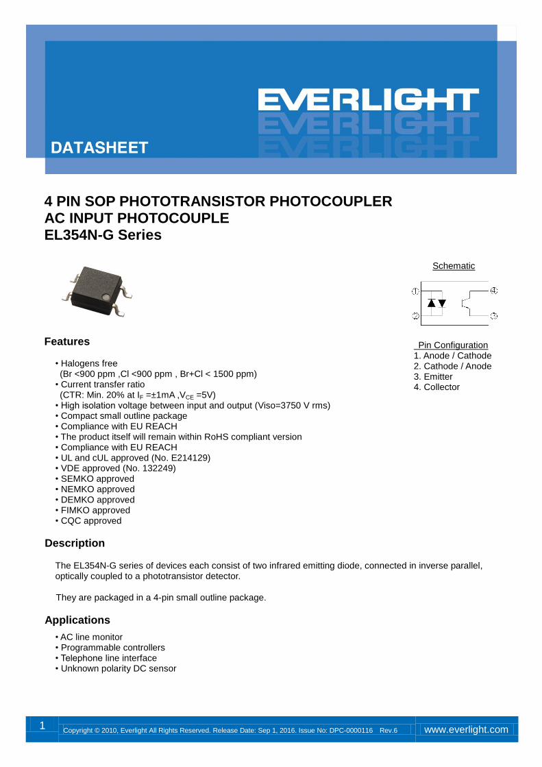
The EL354N-G series of devices each consist of two infrared emitting diode, connected in inverse parallel, optically coupled to a phototransistor detector.
.They are packaged in a 4-pin small outline package.
Applications
• AC line monitor • Programmable controllers • Telephone line interface • Unknown polarity DC sensor
Schematic
Pin Configuration 1. Anode / Cathode 2. Cathode / Anode 3. Emitter 4. Collector
DATASHEET 4 PIN SOP PHOTOTRANSISTOR PHOTOCOUPLER AC INPUT PHOTOCOUPLE EL354N-G Series
2 Copyright © 2010, Everlight All Rights Reserved. Release Date: Sep 1, 2016. Issue No: DPC-0000116 Rev.6 www.everlight.com
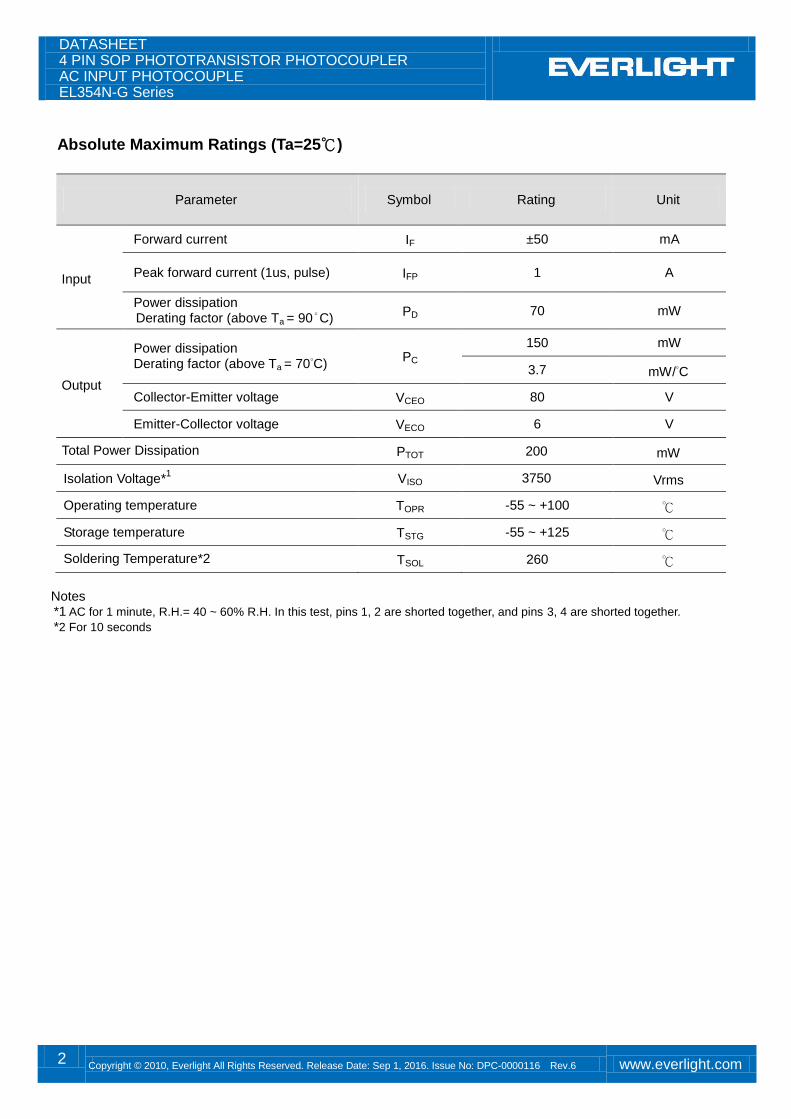
Absolute Maximum Ratings (Ta=25℃)
Parameter Symbol Rating Unit
Input
Forward current IF ±50 mA
Peak forward current (1us, pulse) IFP 1 A
Power dissipation Derating factor (above Ta = 90°C) PD 70 mW
Output
Power dissipation Derating factor (above Ta = 70°C)
PC 150 mW
3.7 mW/°C
Collector-Emitter voltage VCEO 80 V
Emitter-Collector voltage VECO 6 V
Total Power Dissipation PTOT 200 mW
Isolation Voltage*1 VISO 3750 Vrms
Operating temperature TOPR -55 ~ +100 ℃
Storage temperature TSTG -55 ~ +125 ℃
Soldering Temperature*2 TSOL 260 ℃
Notes *1 AC for 1 minute, R.H.= 40 ~ 60% R.H. In this test, pins 1, 2 are shorted together, and pins 3, 4 are shorted together.
*2 For 10 seconds
DATASHEET 4 PIN SOP PHOTOTRANSISTOR PHOTOCOUPLER AC INPUT PHOTOCOUPLE EL354N-G Series
3 Copyright © 2010, Everlight All Rights Reserved. Release Date: Sep 1, 2016. Issue No: DPC-0000116 Rev.6 www.everlight.com
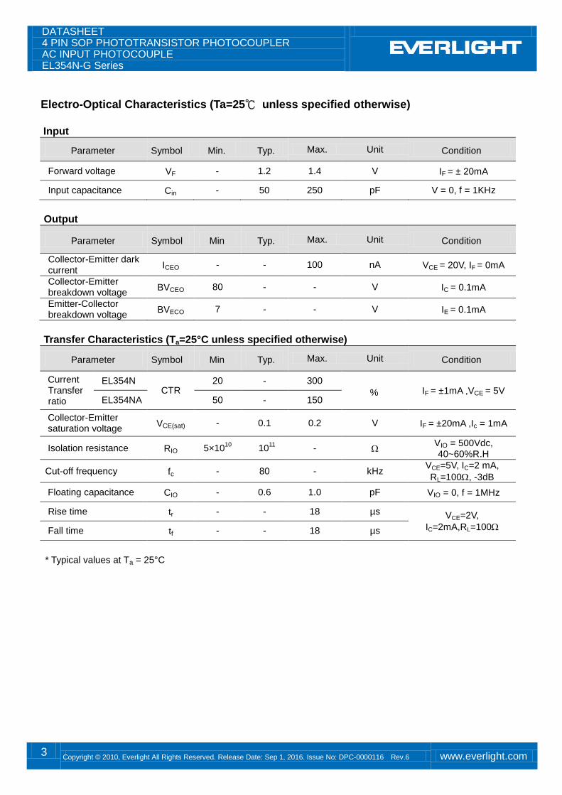
Electro-Optical Characteristics (Ta=25℃ unless specified otherwise)
Input
Parameter Symbol Min. Typ. Max. Unit Condition
Forward voltage VF - 1.2 1.4 V IF = ± 20mA
Input capacitance Cin - 50 250 pF V = 0, f = 1KHz
Output
Parameter Symbol Min Typ. Max. Unit Condition
Collector-Emitter dark current
ICEO - - 100 nA VCE = 20V, IF = 0mA
Collector-Emitter breakdown voltage
BVCEO 80 - - V IC = 0.1mA
Emitter-Collector breakdown voltage
BVECO 7 - - V IE = 0.1mA
Transfer Characteristics (Ta=25°C unless specified otherwise)
Parameter Symbol Min Typ. Max. Unit Condition
Current Transfer ratio
EL354N CTR
20 - 300
% IF = ±1mA ,VCE = 5V EL354NA 50 - 150
Collector-Emitter saturation voltage
VCE(sat) - 0.1 0.2 V IF = ±20mA ,Ic = 1mA
Isolation resistance RIO 5×10¹⁰
1011
- VIO = 500Vdc, 40~60%R.H
Cut-off frequency fc - 80 - kHz VCE=5V, IC=2 mA,
RL=100, -3dB
Floating capacitance CIO - 0.6 1.0 pF VIO = 0, f = 1MHz
Rise time tr - - 18 µs VCE=2V,
IC=2mA,RL=100 Fall time tf - - 18 µs
* Typical values at Ta = 25°C
DATASHEET 4 PIN SOP PHOTOTRANSISTOR PHOTOCOUPLER AC INPUT PHOTOCOUPLE EL354N-G Series
4 Copyright © 2010, Everlight All Rights Reserved. Release Date: Sep 1, 2016. Issue No: DPC-0000116 Rev.6 www.everlight.com
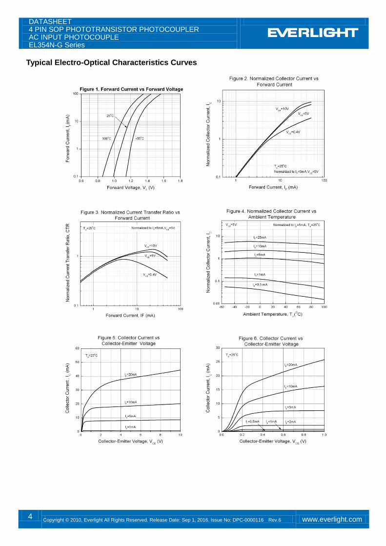
Typical Electro-Optical Characteristics Curves
DATASHEET 4 PIN SOP PHOTOTRANSISTOR PHOTOCOUPLER AC INPUT PHOTOCOUPLE EL354N-G Series
5 Copyright © 2010, Everlight All Rights Reserved. Release Date: Sep 1, 2016. Issue No: DPC-0000116 Rev.6 www.everlight.com
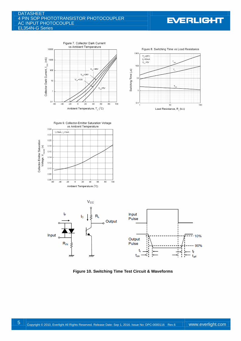
Figure 10. Switching Time Test Circuit & Waveforms
DATASHEET 4 PIN SOP PHOTOTRANSISTOR PHOTOCOUPLER AC INPUT PHOTOCOUPLE EL354N-G Series
6 Copyright © 2010, Everlight All Rights Reserved. Release Date: Sep 1, 2016. Issue No: DPC-0000116 Rev.6 www.everlight.com
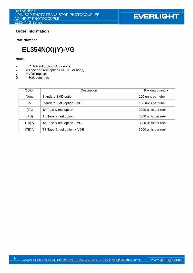
Order Information Part Number
EL354N(X)(Y)-VG Notes X = CTR Rank option (A, or none) Y = Tape and reel option (TA, TB, or none). V = VDE (option) G = Halogens free
Option Description Packing quantity
None Standard SMD option 100 units per tube
-V Standard SMD option + VDE 100 units per tube
(TA) TA Tape & reel option 3000 units per reel
(TB) TB Tape & reel option 3000 units per reel
(TA)-V TA Tape & reel option + VDE 3000 units per reel
(TB)-V TB Tape & reel option + VDE 3000 units per reel
DATASHEET 4 PIN SOP PHOTOTRANSISTOR PHOTOCOUPLER AC INPUT PHOTOCOUPLE EL354N-G Series
7 Copyright © 2010, Everlight All Rights Reserved. Release Date: Sep 1, 2016. Issue No: DPC-0000116 Rev.6 www.everlight.com
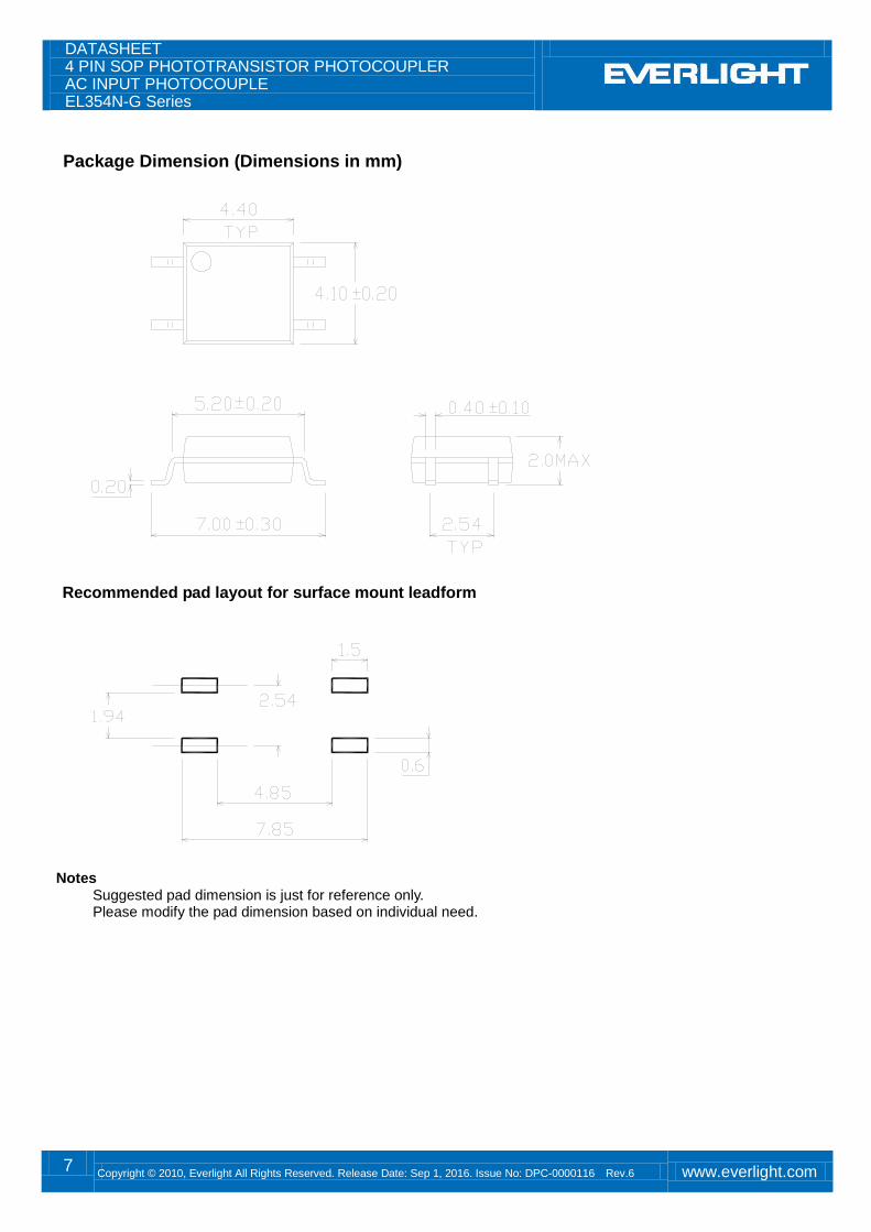
Package Dimension (Dimensions in mm)
Recommended pad layout for surface mount leadform
Notes Suggested pad dimension is just for reference only.
Please modify the pad dimension based on individual need.
DATASHEET 4 PIN SOP PHOTOTRANSISTOR PHOTOCOUPLER AC INPUT PHOTOCOUPLE EL354N-G Series
8 Copyright © 2010, Everlight All Rights Reserved. Release Date: Sep 1, 2016. Issue No: DPC-0000116 Rev.6 www.everlight.com
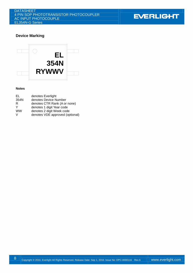
Device Marking
Notes EL denotes Everlight 354N denotes Device Number R denotes CTR Rank (A or none) Y denotes 1 digit Year code WW denotes 2 digit Week code V denotes VDE approved (optional)
EL 354N
RYWWV
DATASHEET 4 PIN SOP PHOTOTRANSISTOR PHOTOCOUPLER AC INPUT PHOTOCOUPLE EL354N-G Series
9 Copyright © 2010, Everlight All Rights Reserved. Release Date: Sep 1, 2016. Issue No: DPC-0000116 Rev.6 www.everlight.com
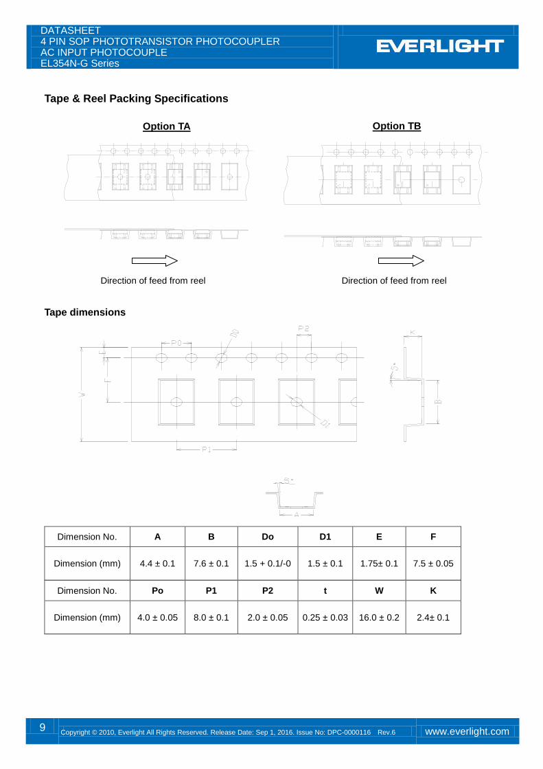
Tape & Reel Packing Specifications
Tape dimensions
Dimension No. A B Do D1 E F
Dimension (mm) 4.4 ± 0.1 7.6 ± 0.1 1.5 + 0.1/-0 1.5 ± 0.1 1.75± 0.1 7.5 ± 0.05
Dimension No. Po P1 P2 t W K
Dimension (mm) 4.0 ± 0.05 8.0 ± 0.1 2.0 ± 0.05 0.25 ± 0.03 16.0 ± 0.2 2.4± 0.1
Direction of feed from reel Direction of feed from reel
Option TA Option TB
DATASHEET 4 PIN SOP PHOTOTRANSISTOR PHOTOCOUPLER AC INPUT PHOTOCOUPLE EL354N-G Series
10 Copyright © 2010, Everlight All Rights Reserved. Release Date: Sep 1, 2016. Issue No: DPC-0000116 Rev.6 www.everlight.com
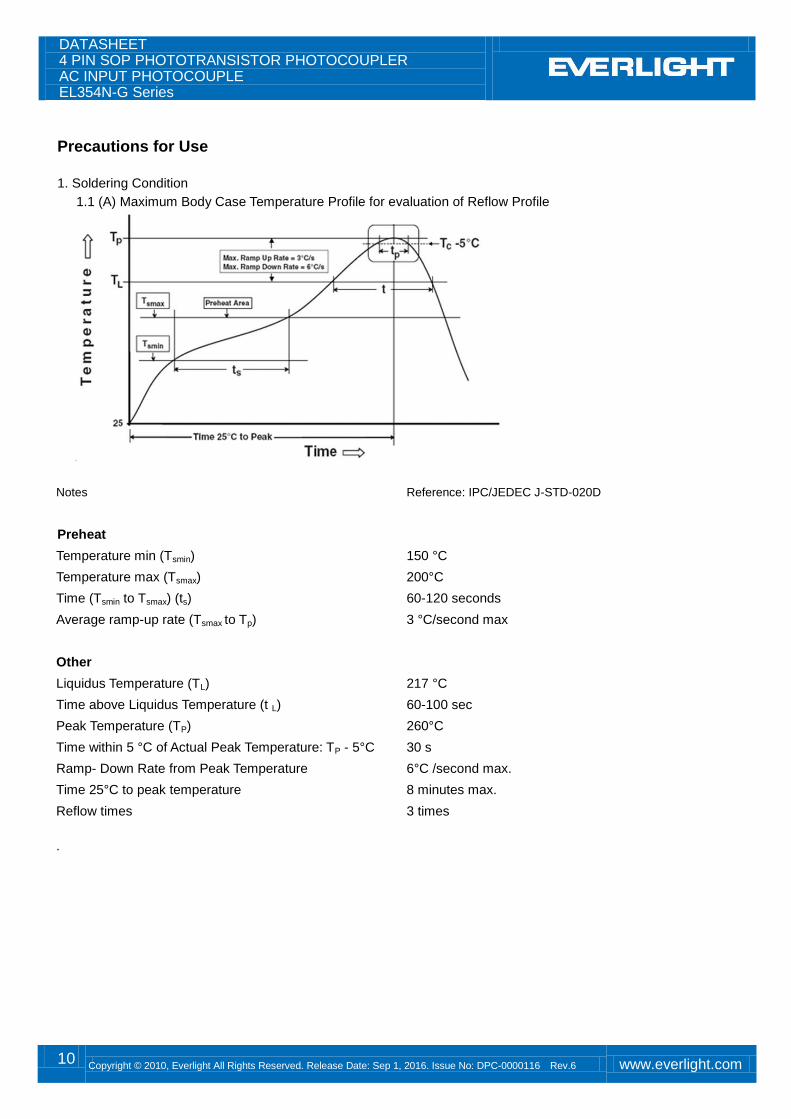
Precautions for Use
1. Soldering Condition
1.1 (A) Maximum Body Case Temperature Profile for evaluation of Reflow Profile
Notes Reference: IPC/JEDEC J-STD-020D
Preheat
Temperature min (Tsmin) 150 °C
Temperature max (Tsmax) 200°C
Time (Tsmin to Tsmax) (ts) 60-120 seconds
Average ramp-up rate (Tsmax to Tp) 3 °C/second max
Other
Liquidus Temperature (TL) 217 °C
Time above Liquidus Temperature (t L) 60-100 sec
Peak Temperature (TP) 260°C
Time within 5 °C of Actual Peak Temperature: TP - 5°C 30 s
Ramp- Down Rate from Peak Temperature 6°C /second max.
Time 25°C to peak temperature 8 minutes max.
Reflow times 3 times .
DATASHEET 4 PIN SOP PHOTOTRANSISTOR PHOTOCOUPLER AC INPUT PHOTOCOUPLE EL354N-G Series
11 Copyright © 2010, Everlight All Rights Reserved. Release Date: Sep 1, 2016. Issue No: DPC-0000116 Rev.6 www.everlight.com
DISCLAIMER
1. Above specification may be changed without notice. EVERLIGHT will reserve authority on material change for above
specification.
2. When using this product, please observe the absolute maximum ratings and the instructions for using outlined in these
specification sheets. EVERLIGHT assumes no responsibility for any damage resulting from use of the product which
does not comply with the absolute maximum ratings and the instructions included in these specification sheets.
3. These specification sheets include materials protected under copyright of EVERLIGHT corporation. Please don’t
reproduce or cause anyone to reproduce them without EVERLIGHT’s consent.
4. These specification sheets include materials protected under copyright of EVERLIGHT. Reproduction in any form is
prohibited without the specific consent of EVERLIGHT.
5. This product is not intended to be used for military, aircraft, automotive, medical, life sustaining or life saving
applications or any other application which can result in human injury or death. Please contact authorized Everlight
sales agent for special application request.
6. Statements regarding the suitability of products for certain types of applications are based on Everlight’s knowledge of
typical requirements that are often placed on Everlight products in generic applications. Such statements are not
binding statements about the suitability of products for a particular application. It is the customer’s responsibility to
validate that a particular product with the properties described in the product specification is suitable for use in a
particular application. Parameters provided in datasheets and/or specifications may vary in different applications and
performance may vary over time. All operating parameters, including typical parameters, must be validated for each
customer application by the customer’s technical experts. Product specifications do not expand or otherwise modify
Everlight’s terms and conditions of purchase, including but not limited to the warranty expressed therein.