Embed Size (px)
Citation preview

SEPTEMBER 199916-40094-101
4-PLAYER, 25”DEDICATED
VIDEO GAME
TM
OperationManual
Installing Operating Testing Parts Wiring Diagrams Troubleshooting
MIDWAY GAMES INC., 3401 North California Avenue, Chicago, Illinois 60618–5899 USA
http://www.midway.com


1-1
SPORTSTATION TM
C H A P T E RO N E
SAFETY, SPECIFICATIONS,INSPECTION & INSTALLATION
NOTICE: This manual is subject to change without notice. MIDWAY reserves the right to makeimprovements in equipment function, design, or components as progress in engineering ormanufacturing methods may warrant.
Fill out and mail in the Game Information Card. Include the game serial number from the label onthe rear of the cabinet. For your records, write the game serial number in the manual.SERIAL NUMBER _______________________________________________________

1-2
SAFETY INSTRUCTIONS
The following safety instructions apply to operators and service personnel. Read these instructions beforepreparing your game for play. Other safety instructions appear throughout this manual.
DEFINITIONS OF SAFETY TERMS
DANGER indicates an imminent hazard. If you fail to avoid this hazard, it WILL cause death or seriousinjury.
WARNING indicates a potential hazard. If you fail to avoid this hazard, it COULD cause death or seriousinjury.
CAUTION indicates a potential hazard. If you fail to avoid this hazard, it MAY cause minor or moderateinjury. CAUTION also alerts you about unsafe practices.
NOTICE indicates information of special importance.
WARNING: TRANSPORTING GAMES. This game contains glass and fragileelectronic devices. Use appropriate care when transporting this game. Avoid roughhandling when moving the cabinet. Don’t move this game with the power on.
WARNING: DISCONNECT POWER. Always turn the power OFF and unplug the gamebefore attempting service or adjustments. Installing or repairing PC boards with powerON can damage components and void the warranty. Be sure that you securely installground wires.
WARNING: GROUND GAMES. Avoid electrical shocks! Don’t plug in a game untilyou have inspected and properly grounded it. Only plug this game into a grounded,three-wire outlet. Don’t use a “cheater” plug, or cut off the ground pin on the line cord.
WARNING: HAZARD TO EPILEPTICS. A small portion of the population has acondition which may cause epileptic seizures or momentary loss of consciousnesswhen viewing certain kinds of flashing lights or patterns that are present in our dailyenvironment. These persons may experience seizures while watching some kinds oftelevision pictures or playing certain video games. People who have not had seizuresmay nonetheless have an undetected epileptic condition.
If you or anyone in your family has experienced symptoms linked to an epilepticcondition (e.g., seizures or loss of awareness), consult your physician before usingvideo games.
We recommend that parents observe their children while they play video games. If youor your child experience the following symptoms: dizziness, altered vision, eye ormuscle twitching, involuntary movements, loss of awareness, disorientation, orconvulsions, discontinue use immediately and consult your physician.
WARNING: AVOID ELECTRICAL SHOCKS. This video game system does not utilizean isolation transformer. Internal, cabinet AC isn’t isolated from the external, AC line.

1-3
WARNING: HANDLE FLUORESCENT TUBE AND CRT WITH CARE. If you drop afluorescent tube or CRT and it breaks, it will implode! Shattered glass can fly eight feetor more from the implosion.
CAUTION: CHECK POWER SELECTOR, LAMP. Set the 110/220VAC selector on thepower supply for the correct line voltage. Check the selector setting before switchingon the game. Verify that the fluorescent lamp assembly is correct for the local linevoltage.
CAUTION: USE PROPER FUSE. Avoid electrical shock! Replacement fuses must beof the same type as those they replace. Fuse voltage and current ratings must matchratings on the original fuse.
CAUTION: ATTACH CONNECTORS PROPERLY. Be sure that printed circuit board(PCB) connectors mate properly. If connectors don’t slip on easily, don’t force them. Areversed connector may damage your game and void the warranty. Connector keysonly allow a connector to fit one set of pins on a board.
CAUTION: TAKE CARE WHEN SHIPPING HARD DISKS. The hard disk drive mustbe packed in an anti-static bag. When shipping the drive for repair or replacement,pack it in an approved container (P/N 08-8068). Never stack or drop hard disk drives.
PRODUCT SPECIFICATIONSOperating Requirements
LocationDomesticForeignJapan
Electrical Power120VAC @ 60Hz 3.0 Amps230VAC @ 50Hz 2.0 Amps100VAC @ 50Hz 3.0 Amps
Temperature32°F to 100°F(0°C to 38°C)
HumidityNot to exceed 95% relative
Cabinet StatisticsShipping Dimensions (One Piece)Carton Main Cabinet Player Control PanelWidth 29" (73.7 cm) 37” (94.0 cm)Depth 43" (109.2 cm) 13” (33.0 cm)Height 75" (190.5 cm) 7” (17.8 cm)
Shipping WeightApprox. 385 Lbs.(175 kg.)
Design TypeDedicated Video Game with49-Way, Optodetector Joysticks
Equipment CharacteristicsVideo Display MonitorMedium Resolution RGB25” (63.5 cm) CRT
Audio SystemDigital Stereo Sound5” (12.7 cm) Coaxial,Full-Range Speakers
Currency Acceptors2 Coin MechanismsDollar Bill Validator ReadyElectronic Coin Acceptor Ready
Game CharacteristicsPlayer Variables1 to 4 players per gameHigh Score Recognition
Operator VariablesCoinage, Play Mode,Difficulty, Volume, Audits,Statistics
DiagnosticsAutomatic Power-Up Self-TestManual, Multi-Level Menu System

1-4
INSTALLATION & INSPECTION
INSTALL THE CONTROL PANEL
WARNING: The cabinet is top heavy. Use the two handles when moving the cabinet.
1. Remove all items from the shipping containers and set them aside. Inspect the exterior of the cabinet,and control panel for damage. Pay special attention to cabinet edges, seams, and corners.
2. Remove and save the screws at the top and sides of the rear door. Unlock the rear door, then lift it offthe cabinet. Set the rear door aside. Inspect the cabinet interior for signs of damage. Check all majorassemblies to assure that they mount securely. Check the joysticks for signs of damage.
3. The coin door keys are on a key hook inside the cabinet. Unlock and open the coin door. Cash boxdoor and rear door keys are on a key hook attached to the rear of the coin door. Unlock and open thecash box door. Remove the spare parts stored in the cash box.
4. Find the leg levelers and nuts in the spare parts bag. Install one nut onto each leg leveler. Hand-turnthe nut against the base of the leg leveler. Install one leveler with its nut into the threaded hole ineach corner of the cabinet. Turn the levelers all the way into the holes, but don’t tighten the levelers.
5. Unpack the player control panel. Place the player panel on the cabinet above the coin door. Open theplayer panel. Align panel-mounting holes with holes in the cabinet. Install bolts with washers (two inback; two on the bottom). Connect wiring harnesses to P1, P2, and P8 on the I-40 Joystick InterfaceBoard. Close the player panel. Reach up through the open coin door and lock both latches.

1-5
6. Refer to the Cabinet Wiring Diagram (Chapter 5). Check to see that cable connectors are correctlysecured. Don’t force connectors. They’re keyed to fit in only one location. Bent pins and reversedconnections may damage your game and void the warranty.
7. You can install an extra padlock to secure the rear door. You’ll find a hasp in the spare parts bag.Remove the two lock bracket nuts from inside the cabinet, above the rear door opening. Slide thehasp onto the bolts so that it protrudes from the hole in back of the cabinet. Reinstall nuts and tighten.
8. Modify the lock plate at the top of the rear door. Remove the bolts and nuts from the lock plate.Rotate the plate so that the slot will be above the door. Reinstall the bolts and nuts and tighten firmly.
INSTALL THE DOOR LOCK AND SECURITY BRACKETS
9. The power cord is with the spare parts. Remove and save four screws from the line cord cover plateat the rear of the cabinet. Match the holes on the IEC plug with the prongs in the receptacle. Push theplug firmly to seat it. Route the cord away from cabinet wheels and foot traffic areas. Hang excesscord on the plastic clip near the vent.

1-6
INSTALL THE LINE CORD
CAUTION: CHECK POWER SUPPLY LINE VOLTAGE SELECTOR SWITCH. Set the110/220 VAC selector on the power supply for the correct local line voltage. Check theselector setting before switching on the game.
10. Reinstall the rear door and close it. Lock the rear door and remove the key. If required, install theextra padlock through the hasp. Install the screws at the top and sides of the rear door. Tighten thescrews snugly. Close and lock the cash box and coin doors.
NOTICE: Tamper-resistant screws and a matching wrench are provided with this gamefor additional security. Four tamper-resistant screws and four wrenches are located inthe spare parts bag. If desired, replace the original screws with the tamper-resistantscrews. Tighten the screws firmly with the wrench.
11. Move the game to its play location. Lower each leg leveler until the cabinet is stable and level. Adjustthe levelers as required to raise wheels and distribute weight equally on each corner. Tighten thenuts.
12. Plug the game into a grounded (3-terminal) AC wall outlet. Switch on the game, using the on/offswitch at the top-left rear of the cabinet. The game will power up and begin self-diagnostics. Ifdiagnostics find no errors, the game enters its Attract Mode of operation. Unlock and open the coindoor. Locate the control switches. Press TEST MODE to enter the Menu System.
13. Select “MONITOR SETUP” at the Diagnostics Menu. Confirm proper video display operation andadjust the monitor as necessary.
14. Select “DISK TESTS” at the Diagnostics Menu. Run all the tests in order to verify correct driveoperation.
15. Select “SWITCH TESTS” at the Diagnostics Menu. Check to be sure that all control switches work.
16. Select “DIP-SWITCH TESTS” at the Diagnostics Menu. Verify that all switches are set to optimumpositions for this game.
17. Select “SPEAKER TEST” at the Diagnostics Menu. Verify operation of audio system components.
18. Select “EXIT” at the Main Menu. The system should enter Game-Over Mode. Open the coin door andpress the SERVICE CREDITS button to allow game play. Choose a joystick and press the STARTbutton to begin play. Listen to the audio while playing the game. Note sound irregularities (phaseproblems, no low frequencies, mono audio from stereo speakers, etc.). If necessary, check the wiringharness for internal shorts or strapped connections.

2-1
SPORTSTATION TM
C H A P T E RT W O
OPERATION, FEATURES,MAINTENANCE & SERVICING

2-2
GAME OPERATION
STARTING UP
Whenever you turn on the machine or restore power, the system executes boot ROM code. The bootROM contains self-diagnostic tests that automatically verify and report the condition of the disk drive andother hardware. The screen is blank during these tests. If the hardware fails a test, the system displaysan error message. The message appears for 30 seconds or until someone presses a button.
• If nobody presses a button, the system quickly completes tests, and then loads game software.
• To skip boot ROM tests and activate the Menu System, press and hold the TEST MODE button.You’ll find this button behind the coin door.
Having passed power-up tests, the system enters Attract Mode. Attract Mode consists of typical gamescenes and sounds, alternating with high scores. Attract Mode continues until game play commences.
Players insert currency or tokens to start the game. Pressing a START determines which player receivesthe credit. The game computer asks whether players want to play NBA Showtime or NFL Blitz 2000 GoldEdition. Players request one or the other via player panel controls. Then players select a team. The gamecomputer associates one team with the Player-1 and Player-2 joysticks. The Player-3 and Player-4joysticks assume control of the opposing team. Play begins after a countdown period. Play progresseslike a real-life football or basketball game. At Game Over Mode, players may choose to begin again. Ifplayers choose not to continue, then the system returns to Attract Mode.
NFL BLITZ 2000 GOLD EDITION GAME RULES
INSTRUCTIONSPlay instructions appear on the information panel over and under the video monitor.
ONE TO FOUR PLAYERSPlayers may enter their names for future reference. Then they select teams and run the first play. Playersmay choose an offensive or defensive play. Additional game information appears on the screen asneeded. Team statistics appear at the end of each quarter.
CONTROLLING CHARACTERSThe joystick and action buttons control characters on the field. The joysticks respond to different amountsof deflection as well as direction.
GAME ACTIONStandard league football rules apply, with two exceptions: First downs require 30 yards, and teams onlyhave seven active players. Game adjustment settings determine game length and speed.
The player view of the action changes automatically whenever a better camera angle becomes available.The game sounds include announcer comments and crowd noises.
SCORINGTouchdowns and field goals score points, just as in real football games.
NFL BLITZ 2000 GOLD EDITION PLAY SELECTION
STANDARD PLAYSThe player may select any of the offensive or defensive plays in the game. Players can choose frompages of standard plays loaded into the game. Use the indicated pushbuttons to view and select anyplay.
CUSTOM PLAYS

2-3
Players may choose to create their own offensive plays rather than depend on the standard plays in thegame. Players can design and name their plays using the CREATE PLAY feature, then store these playsfor future use. These custom plays become available on an additional page of game plays.
NFL BLITZ 2000 GOLD EDITION PLAYER CONTROLS
The player controls are used to maneuver the team members and attack or defend against adversaries.
• START (orange). This button allows players to begin or continue play. Use PLAYER 1 START andPLAYER 2 START to begin a two-player game. START has no game action or service function.
• JUMP / TACKLE. This button lifts the offensive team member up or causes the defensive player totackle opponents. Use this same button to create plays or select menu items during service.
• PASS / CHANGE PLAYER. This button activates offensive throws. The defense move switchesactive control to another teammate. Use this same button to create plays or select menu items duringservice.
• TURBO (white). The TURBO button gives any active character an extra burst of power or speed.Use this same button to create plays or select menu items during service.
• JOYSTICK. Each player has a joystick to control the movements of one on-screen character at atime. Use the joystick to create plays or select menu items during service.
RECOMMENDED PLAYER CONTROL LOCATIONS
NBA SHOWTIME GAME RULES
INSTRUCTIONSPlay instructions appear on the information panel over and under the video monitor.
ONE TO FOUR PLAYERSThe player or players insert currency to start the game. Each player chooses a joystick and presses thenearest START button. Players select a team and two characters. In four-player games, each playercontrols one character. In games with fewer players, each player controls one character. The gamecomputer controls remaining characters. The game displays team scores and statistics at the end of eachquarter. Additional game information appears on screen as needed.

2-4
CONTROLLING CHARACTERSThe joystick and action buttons control characters on the basketball court. The joysticks respond todifferent amounts of deflection as well as direction.

2-5
GAME ACTIONStandard NBA basketball rules apply, except that the game only includes four active characters. Gamesettings determine game length and speed. The player view of the action changes automaticallywhenever a better camera angle becomes available. Game sounds include announcer comments andcrowd noises.
SCORINGThe game awards points for baskets, just as in real basketball games.
NBA SHOWTIME PLAYER CONTROLS
• JOYSTICK. Each player’s joystick controls the position of that player’s characters on the gamescreen.
• PASS/STEAL (the blue button) controls character actions on the game screen. Press PASS/STEALto attempt to pass or steal the ball.
• SHOOT/BLOCK (the red button) controls character actions on the game screen. PressSHOOT/BLOCK to shoot or attempt to block the ball.
• START (orange buttons). Each START button allows the corresponding player to begin or continueplay.
• TURBO (The white button) controls character actions on the game screen. Press TURBO to speedup the pace of a play.
OPERATOR CONTROLS
CABINET CONTROLS
♦ The DIP Switches set some system variables. You can set other variables with diagnostic controlswitches.
♦ The Monitor Remote Control Board allows you to adjust the video display for optimum viewing.
♦ The POWER Switch turns off the game, but does not reset game variables.
DIAGNOSTIC CONTROL SWITCHES
♦ The SERVICE CREDITS Button allots credits without changing the game's bookkeeping total.SERVICE CREDITS has no function in the menu system.
♦ The TEST MODE Button causes the game to enter the service menu system. Press the TESTMODE button briefly to run automatic tests. To make game adjustments, press and hold TESTMODE until the Main Menu appears. Within the menu system, TEST MODE assumes anotherfunction. There, it selects a menu line item and calls up the item’s submenu. The screen displays thissubmenu.
♦ VOLUME DOWN and VOLUME UP Buttons set game sound levels. To make minor volumechanges, press either button briefly. To make major changes, press and hold a button. In the menusystem, VOLUME UP moves the item highlight bar up the menu. VOLUME DOWN moves the itemhighlight bar downward.
NOTICE: You must adjust Attract Mode volume independently of Game Mode volume.For greater profits, increase volume levels to draw attention to this game.

2-6
PLAYER CONTROLS

2-7
DIAGNOSTIC CONTROL SWITCH LOCATIONS
PLAYER CONTROL LOCATIONS

2-8
MAINTENANCE
♦ CabinetUse only non-abrasive cleaners to avoid damaging game graphics. Apply cleaner to a clean cloth orsponge. Wipe the screen clean with this cloth or sponge. Do not apply cleaner directly on the cabinet!
♦ Control PanelDirt or debris on the joysticks or buttons can affect earnings. Apply the cleaner to a clean cloth. Usethe cloth to wipe the controls. Don’t apply the cleaner directly to the controls!
♦ Viewing GlassTo clean the glass, you don’t need to switch off power to the game. Apply a mild glass cleaner to aclean cloth or sponge. Use this to wipe the viewing glass. Do not apply the cleaner directly on theglass! Liquid could drip down into switch or motor circuits and cause erratic game operation.
SERVICINGOnly qualified service personnel should perform maintenance and repairs. The following productguidelines apply to all game operators and service personnel. Notes, cautions and warnings appearthroughout this manual where they apply. Read the SAFETY pages thoroughly before beginning service.
♦ Circuit Board SetThe SportStation game computer uses a set of three circuit boards. The three boards include theCPU Board, I/O Board and Video Board. Switch off power to the game. Open the rear door. Toexpose the circuit boards, remove their perforated metal cover. Carefully note the orientation of theJAMMA connector and other cables. Extract the harness and hard disk drive ribbon cable from theboard connectors. Remove circuit board mounting screws. Lift the circuit boards out of the cabinetand set them in a safe place. Use anti-static packaging from new parts to store boards that you won’treinstall.
CAUTION: Circuit board edge connectors are fragile. Take care when separatingboards in the board set. Never jam the board connectors together. Never plug themtogether on an extreme angle. If necessary, carefully straighten bent pins with asmall, grounded flat blade screwdriver. Also, don’t touch exposed foil on printedcircuit boards. Skin oils are corrosive.
NOTICE: Avoid damage to game electronics! Turn off game power before servicingcircuit boards or any electronic assembly. Never “hot plug” circuit boards.
♦ Coin MechanismSwitch off power to the game. Unlock the coin door and swing it open. To clean or replace a coinmechanism, unlatch and remove it. After reinstallation, ensure that the mechanism seats fully itsbracket. Close and lock the release latch, and then close the door. Turn on the game and change themechanism setup. Test known good and bad coins to verify operation.
♦ Coin MeterSwitch off power to the game. Unlock the cash door and swing it open. The coin meter mounts to ametal plate at the bottom the cash vault. Record the meter count before testing or replacement.Remove the plate’s four mounting screws, and then remove the plate.

2-9
Disconnect the meter wiring harness at the connectors. Remove front screws and slide the meter out.Assure that a protective diode connects across the replacement meter’s terminals. The diodeprevents driver circuit damage.

2-10
REINSTALLING CIRCUIT BOARD ASSEMBLIES

2-11
♦ Hard Disk DriveSwitch off power to the game. Unlock and remove the rear cabinet door. Remove the perforatedmetal cover over the game electronics. Disconnect the DC power cable from the hard disk drive.Unplug the ribbon cable from the hard drive. Don’t disconnect the cables from the CPU Board.Loosen the drive mounting screws and lift the drive out of its mounting bracket. Remove the screws.Save them for reuse in future hard drive installations. When returning a hard drive to your distributor,pack it in an anti-static bag. Box the drive in approved shipping container 08-8068.
NOTICE: Hard disk drives are very fragile! Handle them with care. Do not stackor drop hard disk drives. Keep disk drives away from magnets, heat and vibration.
♦ JoysticksSwitch off power to the game. Open the player control panel. Mark and disconnect the wiring harnessfrom a joystick. To separate the joystick from the player panel, first remove the joystick shaft. An E-ring secures the shaft. Disengage this E-ring with a small, flatblade screwdriver. Grasp the joystickknob. Extract the stick from the assembly. Then remove 8-32 tamper-resistant (KEPS®) nuts from thecorners of the joystick base. Retain fasteners for reassembly.

2-12
♦ Memory
CAUTION: Static electricity builds up on your body. This static can damage ordestroy sensitive the game circuits. BEFORE touching or handling electronicassemblies, discharge static electricity by touching the electronics mounting plate.
NOTICE: CPU Board and SI/O Board chips don’t face same direction. Whenmounting chips on either board, refer only to chips on the same board forreference. Never use the chips on another board for reference.
ROM (Read Only Memory) circuits contain computer operating instructions for this game. Switch offpower to the game. Unlock and remove the rear door. Remove the perforated metal cover. Note theROM chip position. Remove the device with a chip extraction tool. To reinstall a ROM chip, orient thedevice over its socket. Press the chip firmly to seat pins. Don’t force the chip into the socket.
CABINET FRONT VIEW
EXTERNAL COMPONENTS

2-13
GAME ELECTRONICS
INTERNAL COMPONENTS
♦ Monitor Bezel Switch off power to the game. Open the control panel. Remove the viewing glass. Lift the bezel upand off the monitor. Set the bezel aside. Clean the labels. Orient the labels right side up, so thatplayers can read them. Reinstall the bezel.
♦ Viewing GlassSwitch off power to the game. Open the control panel. Loosen three mounting screws. Slide the blackmetal strip from the bottom of the glass. Carefully slide the glass from the side grooves. Then lift itclear of the cabinet. Set the glass in a safe place. Clean the glass before reinstalling it.
♦ Monitor
CAUTION: The video monitor is heavy, with most of the weight toward the front ofthe assembly. Support the monitor as you remove it from the cabinet.

2-14
WARNING: The monitor doesn’t require isolation from AC line voltage duringnormal game operation. When operating the monitor outside the cabinet, use anisolation transformer. Connect the transformer between the monitor and line.
Switch off power to the game. Open the control panel. Remove the viewing glass and monitor bezel.Unlock and remove the rear door. Disconnect the monitor from the wiring harness, remoteadjustment board, and ground wires. Remove the fasteners that secure the monitor frame to itsmounting panel. Carefully pull the monitor from the cabinet. Set the monitor in a safe place. Removethe remote adjustment board from the cabinet and reconnect it to the monitor before servicing orreplacement. Clean the face of the monitor before reinstalling the monitor bezel.
♦ Power SupplySwitch off power to the game. Unlock and remove the rear door. Remove the electronics rack and setit aside. Unplug the IEC AC connector from the rear of the supply. Unplug the power wiringharnesses from the back of the supply. Remove two front and two rear screws from the supply. Liftthe supply off the power chassis. Slide the supply out of the cabinet.
Reinstallation. Verify the line voltage switch setting before reinstalling the power supply. Set thevoltage switch to the correct value. Place the supply on the power chassis. Align the chassismounting holes. Install the four screws and two power connectors. Connect the IEC AC connector tothe rear of the supply. Replace the electronics rack. Plug the power wiring harnesses into the back ofthe supply. Replace and lock the rear door. Switch on power to the game.
♦ SpeakersSwitch off power to the game. The full-range speakers are mounted behind grilles at the top of theplayer panel. Grilles and speakers come out from the front. Remove the screws and set the grillesaside. To avoid damaging a speaker, remove upper mounting screws first, and replace them last.
Remove the speakers from the enclosure just enough to expose the terminals. Label and disconnectthe wires. Refer to the Wiring Diagram (Chapter Five) for speaker wiring information. Don’t useexcess force when removing or tightening screws threaded into plastic or particle board.

3-1
SPORTSTATION TM
C H A P T E RT H R E E
DIAGNOSTIC, AUDIT &ADJUSTMENT MENU SYSTEM
FOR NFL BLITZ 2000 GOLD EDITION GAMES
NOTICE: Information in this manual is subject to change without notice. Midway reserves theright to make improvements in equipment as progress in engineering warrants.
NOTICE: GAME-SELECTION SWITCH. Select NBA Showtime or NFL Blitz by flippingswitch 8 at DIP bank U13. Then power down and up again. The Attract Mode for thegame you select will appear. The player can still play either game.

3-2
MENU SYSTEM
WHAT IS THE MENU SYSTEM?The game’s Menu System is a series of auditing, game adjustment and diagnostic screens. You caneasily access and apply these screens to optimize game performance. For instance…
• Use game audits screens to assess game performance.• Use adjustment screens to help you to customize game performance. For instance, you can restore
factory default game settings. You can also calibrate player controls for accuracy.• Use diagnostic screens to verify proper equipment operation.
ACTIVATING THE MENU SYSTEMOpen the coin door. Find the TEST MODE switch inside. Press TEST MODE to invoke the Menu System.The game system responds by exiting Game Mode and entering Diagnostic Mode.
AUTOMATIC TESTSIn Diagnostic Mode, the Power-On Self-Test (POST) activates. This routine runs automatically. It candetect faults that cause game or Menu System malfunctions. POST usually takes less than a minute. Thetest doesn’t display anything. Instead, the system boot loader indicates the software revision number andserial numbers. The system boot loader also displays a sound-loading message and other usefulinformation.
At the end of POST, the system displays the Control Functions Menu.
CONTROL FUNCTIONS MENUThe Control Functions Menu is purely informational. It appears for five seconds. Then the Menu Systemautomatically displays the Dual Game Adjustment Menu.
The Control Functions Menu introduces the menu navigation controls. The key point is that you can useeither player or diagnostic controls to navigate menus. Diagnostic control switches are particularly helpfulwhen you must troubleshoot player switches. This manual discusses the controls in more detail in thischapter’s Main Menu section. Also see the page on the menu that interests you.
STICK UP/VOLUME UP – MOVE UPSTICK DOWN/VOLUME DOWN – MOVE DOWN
STICK RIGHT – MOVE RIGHTSTICK LEFT – MOVE LEFT
PUSH BUTTON/TEST BUTTON - SELECT
5 SECONDS TO DIAG ENTRY
CONTROL FUNCTIONS MENU

3-3
DUAL GAME ADJUSTMENT MENUThe Dual Game Adjustment Menu is another informational, read-only menu. It appears until you chooseto exit. This menu reminds you that some NFL settings also affect NBA game play. Press any button toexit to the Main Menu.
ATTENTION!
ANY CHANGES TO THE FOLLOWING ADJUSTMENTSUPDATE BOTH NBA AND NFL
PRICINGFREE PLAY
VOLUME LEVELDISCOUNT PRICE / CREDITS
ATTRACT MODE SOUND ON / OFF
THIS ALSO INCLUDES DEFAULT ADJUSTMENTSAND
FULL FACTORY RESTORE FUNCTIONS.
PRESS ANY BUTTON TO EXIT.
DUAL GAME ADJUSTMENT MENU
MAIN MENUThe Main Menu offers you access to the game machine’s test, bookkeeping and programmable features.Game audits, adjustments and diagnostics are line items on the Main Menu. Selecting an item opens itssubmenu. Every submenu presents various options that you may act upon.
NFL MAIN MENU
DIAGNOSTICSAUDITS
ADJUSTMENTSVOLUME LEVEL
UTILITIESNBA MAIN MENU
EXIT TO NBAEXIT TO NFL
MAIN MENUMENU LAYOUTMenus differ, but related information tends to occupy the same screen locations.
• The block at the top, center of each screen displays the current menu title.• Data (menu items, video signals, statistics, reports, etc.) appears in the center of the screen.• Messages (explanations, control functions, revision levels) display at the bottom of the screen.
MENU NAVIGATION CONTROLSUse any player panel joystick to highlight a desired menu item. You can only select one highlighted itemat a time. To select a highlighted item, press any player panel button. Operator control buttons inside thecoin door serve as backup menu navigation controls. Press VOLUME UP or VOLUME DOWN buttons tohighlight a menu item. Press TEST MODE to select a highlighted item.
EXIT OPTIONSTo exit the NFL menus and simultaneously enter the NBA menus, choose NBA MAIN MENU. To returnthe game to play, highlight either EXIT TO NFL or EXIT TO NBA. Your choice determines the game thatwill boot. Next, press any button.

3-4
Main Menu (continued)Diagnostics Menu
DIAGNOSTICSSelect DIAGNOSTICS at the Main Menu. Diagnostic tests allow you to verify the condition of the electricaland electronic hardware in the game.
Highlight a test with any player panel joystick. Select the option with any player panel button.
DIAGNOSTICS
MONITOR SETUPSYSTEM INFO
SOUND SUBSYSTEMDISK TESTS
SWITCH TESTSDIP-SWITCH TESTS
SPEAKER TESTEXIT
DIAGNOSTICS MENU
Diagnostic tests assist you in checking and adjusting the game’s major systems. By running diagnostics,you can gain an insight into both system hardware and game software. Periodically running diagnostics isa crucial part of maintaining game performance and player satisfaction. Sometimes you can improvegame performance by running a diagnostic test and making appropriate adjustments.

3-5
Main Menu (continued)Diagnostics Menu (continued)
Monitor Setup Menu
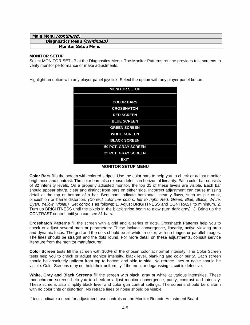
MONITOR SETUPSelect MONITOR SETUP at the Diagnostics Menu. The Monitor Patterns routine provides test screens toverify monitor performance or make adjustments.
Highlight an option with any player panel joystick. Select the option with any player panel button.
MONITOR SETUP
COLOR BARSCROSSHATCHRED SCREEN
BLUE SCREENGREEN SCREENWHITE SCREENBLACK SCREEN
50 PCT. GRAY SCREEN25 PCT. GRAY SCREEN
EXIT
MONITOR SETUP MENU
Color Bars fills the screen with colored stripes. Use the color bars to help you to check or adjust monitorbrightness and contrast. The color bars also expose defects in horizontal linearity. Each color bar consistsof 32 intensity levels. On a properly adjusted monitor, the top 31 of these levels are visible. Each barshould appear sharp, clear and distinct from bars on either side. Incorrect adjustment can cause missingdetail at the top or bottom of a bar. Bent bars indicate horizontal linearity flaws, such as pie crust,pincushion or barrel distortion. (Correct color bar colors, left to right: Red, Green, Blue, Black, White,Cyan, Yellow, Violet.) Set controls as follows: 1. Adjust BRIGHTNESS and CONTRAST to minimum. 2.Turn up BRIGHTNESS until the pixels in the black stripe begin to glow (turn dark gray). 3. Bring up theCONTRAST control until you can see 31 bars.
Crosshatch Patterns fill the screen with a grid and a series of dots. Crosshatch Patterns help you tocheck or adjust several monitor parameters: These include convergence, linearity, active viewing areaand dynamic focus. The grid and the dots should be all white in color, with no fringes or parallel images.The lines should be straight and the dots round. For more detail on these adjustments, consult serviceliterature from the monitor manufacturer.
Color Screen tests fill the screen with 100% of the chosen color at normal intensity. The Color Screentests help you to check or adjust monitor intensity, black level, blanking and color purity. Each screenshould be absolutely uniform from top to bottom and side to side. No retrace lines or noise should bevisible. Color Screens may not hold their uniformity if the monitor degaussing circuit is defective.
White, Gray and Black Screens fill the screen with black, gray or white at various intensities. Thesemonochrome screens help you to check or adjust monitor convergence, purity, contrast and intensity.These screens also simplify black level and color gun control settings. The screens should be uniformwith no color tints or distortion. No retrace lines or noise should be visible.
If tests indicate a need for adjustment, use controls on the Monitor Remote Adjustment Board.
3-6
Main Menu (continued)Diagnostics Menu (continued)
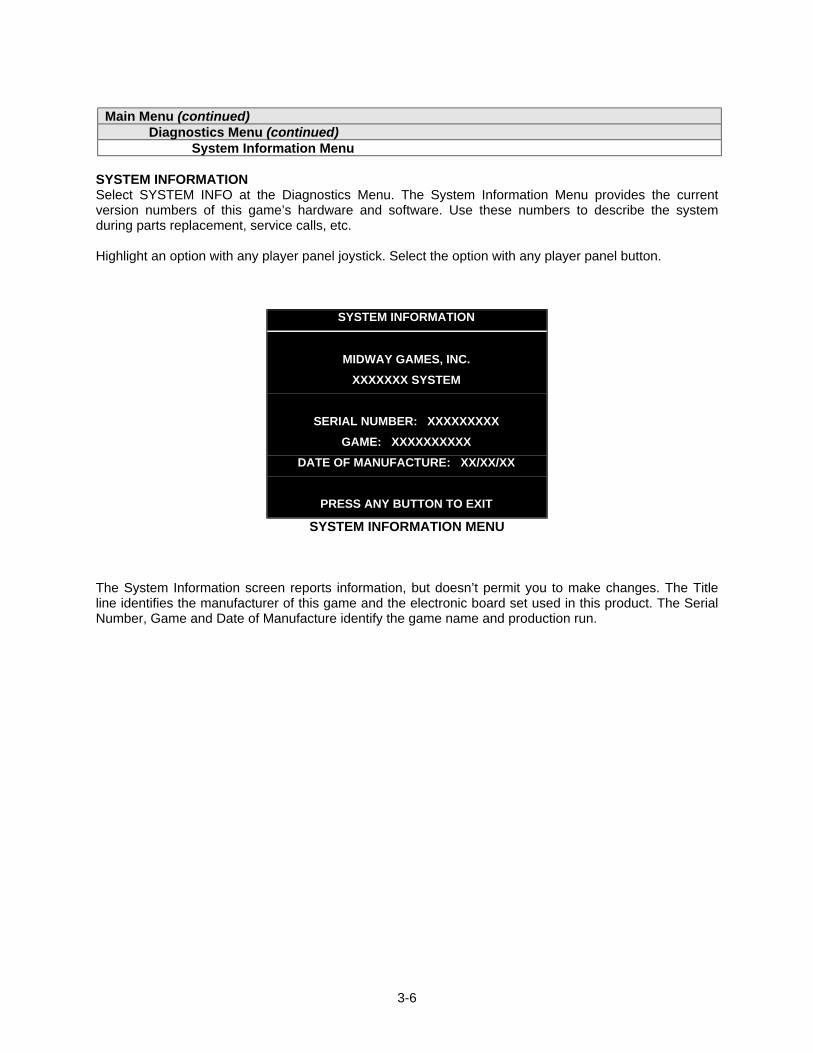
System Information Menu
SYSTEM INFORMATIONSelect SYSTEM INFO at the Diagnostics Menu. The System Information Menu provides the currentversion numbers of this game’s hardware and software. Use these numbers to describe the systemduring parts replacement, service calls, etc.
Highlight an option with any player panel joystick. Select the option with any player panel button.
SYSTEM INFORMATION
MIDWAY GAMES, INC.XXXXXXX SYSTEM
SERIAL NUMBER: XXXXXXXXXGAME: XXXXXXXXXX
DATE OF MANUFACTURE: XX/XX/XX
PRESS ANY BUTTON TO EXIT
SYSTEM INFORMATION MENU
The System Information screen reports information, but doesn’t permit you to make changes. The Titleline identifies the manufacturer of this game and the electronic board set used in this product. The SerialNumber, Game and Date of Manufacture identify the game name and production run.

3-7
Main Menu (continued)Diagnostics Menu (continued)
Sound Subsystem Menu
SOUND SUBSYSTEM TESTSelect SOUND SUBSYSTEM at the Diagnostics Menu. Sound Subsystem Tests verify that audiocomponents are connected and operate properly.
Highlight an option with any player panel joystick. Select the option with any player panel button.
SOUND SUBSYSTEM TEST
BOOT VERSION: XX.XXSDRC VERSION: XX.XXPORT STATUS: GOOD
CHECKSUM: XXXXSRAM: OKDRAM: OK
TONE STATUS: GOODOS VERSION: XX.XX
PRESS ANY BUTTON TO EXIT
SOUND SUBSYSTEM MENU
Version, Status, Checksum and RAM Reports are diagnostic routines. These routines analyze thedigital sound circuits and can detect sound memory problems. Test results appear as numbers ormessages. Sounds may also accompany some tests. Reports other than GOOD or OK indicate aproblem.
3-8
Main Menu (continued)Diagnostics Menu (continued)
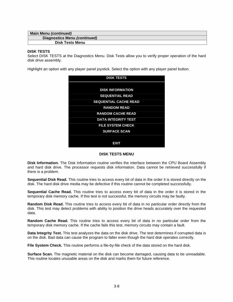
Disk Tests Menu
DISK TESTSSelect DISK TESTS at the Diagnostics Menu. Disk Tests allow you to verify proper operation of the harddisk drive assembly.
Highlight an option with any player panel joystick. Select the option with any player panel button.
DISK TESTS
DISK INFORMATIONSEQUENTIAL READ
SEQUENTIAL CACHE READRANDOM READ
RANDOM CACHE READDATA INTEGRITY TESTFILE SYSTEM CHECK
SURFACE SCAN
EXIT
DISK TESTS MENU
Disk Information. The Disk Information routine verifies the interface between the CPU Board Assemblyand hard disk drive. The processor requests disk information. Data cannot be retrieved successfully ifthere is a problem.
Sequential Disk Read. This routine tries to access every bit of data in the order it is stored directly on thedisk. The hard disk drive media may be defective if this routine cannot be completed successfully.
Sequential Cache Read. This routine tries to access every bit of data in the order it is stored in thetemporary disk memory cache. If this test is not successful, the memory circuits may be faulty.
Random Disk Read. This routine tries to access every bit of data in no particular order directly from thedisk. This test may detect problems with ability to position the drive heads accurately over the requesteddata.
Random Cache Read. This routine tries to access every bit of data in no particular order from thetemporary disk memory cache. If the cache fails this test, memory circuits may contain a fault.
Data Integrity Test. This test analyzes the data on the disk drive. The test determines if corrupted data ison the disk. Bad data can cause the program to falter even though the hard disk operates correctly.
File System Check. This routine performs a file-by-file check of the data stored on the hard disk.
Surface Scan. The magnetic material on the disk can become damaged, causing data to be unreadable.This routine locates unusable areas on the disk and marks them for future reference.

3-9
Main Menu (continued)Diagnostics Menu (continued)
Switch Tests Menu
SWITCH TESTS
Select SWITCH TESTS at the Diagnostics Menu. Switch Tests verify proper operation of the game’sswitches, including buttons and joystick switches.
Activate each switch, and the indicator on the screen changes state. Release the switch and the indicatorreturns to its previous, normally open or closed condition. You can test any combination of switchestogether. To exit the test, simultaneously press the middle two control buttons inside the coin door. TheSwitch Test Screen refers to these buttons as “volume buttons.”
PLAYER SWITCH INPUTS TEST
P1 UP P3 UP LEFT COINP1 DOWN P3 DOWN RIGHT COINP1 LEFT P3 LEFT P1 STARTP1 RIGHT P3 RIGHT SLAM/TILTP1 JUMP P3 JUMP TESTP1 PASS P3 PASS P2 STARTP1 TURBO P3 TURBO SERVICE CREDIT
CENTER COINP2 UP P4 UP EXTRA COINP2 DOWN P4 DOWN P3 STARTP2 LEFT P4 LEFT P4 STARTP2 RIGHT P4 RIGHT VOLUME DOWNP2 JUMP P4 JUMP VOLUME UPP2 PASS P4 PASSP2 TURBO P4 TURBO BILL VALID.
P1 49 WAY P2 49 WAY P3 49 WAY P4 49 WAY24 24 24 24
PRESS BOTH PLAYER 1 AND PLAYER 2 START BUTTONS TO EXIT
SWITCH TEST SCREEN
Switches appear on the screen as colored boxes. Red boxes indicate an open state. Green indicatesclosed. Any other color indicates a fault condition. A single indication on the menu screen should exactlyduplicate a button or joystick change. You’ll notice a unique number for a switch recognized by gameelectronics.
Use Switch Tests to locate crossed wires, intermittent conditions and stuck switches.
NOTICE: Some switches may not be used with this game. If you can’t find one of thelisted switches, check the wiring diagram.

3-10
Main Menu (continued)Diagnostics Menu (continued)
DIP Switch Tests Menu
DIP-SWITCH TESTSSelect DIP-SWITCH TESTS at the Diagnostics Menu. Two 8-position DIP switch banks reside on the SIOBoard. DIP-Switch Tests allow you to check the position of the 16 switches in these banks. You canchange the setting of any DIP switch without removing the circuit board cage.
The screen displays an illustration of each switch block and the current settings. You can change DIP-switch positions with power on. Set any switch, and then check the screen to verify that the new setting isenabled.
Refer to the charts for assistance in choosing switch positions. (* indicates factory defaults.) To exit theDIP-switch Test, press the left control button (inside the coin door).
Game-Selection Switch. Select NBA Showtime or NFL Blitz by flipping switch 8 at DIP bank U13. Thenpower down and up again. After you change the game play, you must change game artwork.
DIP Switch 1 (U13) SW1 SW2 SW3 SW4 SW5 SW6 SW7 SW8Coinage Control DIP Switch
CMOSOffOn*
USA1 Ger1 Fr ECA1 UK1USA2 Ger2 Fr ECA2 UK2USA3 Ger3 Fr ECA3 UK3USA4 Ger4 Fr ECA4 UK4USA5 Ger5 Fr ECA5 UK5USA9 Ger9 Fr ECA9 UK9USA10 Ger10 Fr ECA10 UK ECAUSA ECA / Ger ECA / Fr ECA8Free Play (All Countries)
Off*OnOffOnOffOnOffOnOn
Off*OffOnOnOffOffOnOnOn
Off*OffOffOffOnOnOnOnOn
Country USAFranceGermanyUK**
Off*OnOffOn
Off*OffOnOn
Unused ----
Off*On
Game NBA on NBCNFL Blitz
Off*On
**Except Free Play, which is “on” for SW2 through SW6.
DIP Switch 2 (U12) SW1 SW2 SW3 SW4 SW5 SW6 SW7 SW8Joystick Type 8-Way
49-WayOffOn*
Monitor Resolution Medium ResLow Res
Off*On
Unused ----
Off*On
Unused ----
Off*On
Unused ----
Off*On
Player Panel Type 2-Player4-Player
OffOn*
Power Up Test ActiveInactive
OffOn*
Operating Mode Game ModeTest Mode
Off*On

3-11
Main Menu (continued)Diagnostics Menu (continued)
Speaker Test Menu
SPEAKER TEST
Select SPEAKER TEST at the Diagnostics Menu. The Speaker Test provides audio signals to test theloudspeakers.
Use tests on the Speaker Test menu to verify operation of audio system components. Highlight an optionwith any player panel joystick. Select the option with any player panel button.
SPEAKER TESTS
LEFT CHANNELCENTER CHANNELRIGHT CHANNEL
100 HZ TONE1 KHZ TONEPLAY TUNE
EXIT
SPEAKER TEST MENU
Channel and Tone Tests. The channel subtests employ voice announcements to verify speakerlocations. Use the 100 Hz tone to check the speakers’ bass response. Small speakers with weakmagnets or poor baffles may cause poor bass response.
Play Tune repeats a series of game sounds. Use PLAY TUNE to check speaker operation and fidelity. Ifyour game has stereo speakers, run PLAY TUNE and test speaker phasing. Muddy, weak or distortedsound during this test may indicate crossed wires or out-of-phase speaker connections. Missing soundsmay indicate audio cabling errors.
NOTICE: Check the volume setting before testing. To test the speakers thoroughly,increase the volume level. Before returning to Game-Over Mode, reset the volumelevel to its original setting.

3-12
Main Menu (continued)Audits Menu
AUDITSSelect AUDITS at the Main Menu. The Audits menus permit you to review game play statistics. Additionalmenus give detailed reports for each player position on game starts, ends, cabinet abuse, faultconditions, etc.
Highlight an option with any player panel joystick. Select the option with any player panel button. Thescreen displays a list of the statistics available to you. Select an item to view the detailed report.
AUDITS
COIN AUDITSCREDITS AUDITS
GAME AUDITSTEAM STATS
OFFENSIVE PLAYSDEFENSIVE PLAYSEXCEPTION DUMP
CLEAR AUDITSEXIT
AUDITS MENU
Data in the Audits menus helps you to keep records of the game’s popularity and earning potential. Usethe highlight bar to select the desired subject on the Audits Menu. Each entry on the Audits Menu is thesubject for an entire screen of bookkeeping information. On these screens, you can track favorite teams,frequently used offensive and defensive plays, etc.
Some audits menus also include histograms. Histogram screens allow graphical analysis of statistics.This permits visual comparisons between games. Histograms have no bar graphs until the systemacquires enough data to plot.
Examine and record all game audit values before performing game service or repairs.
NOTICE: Be careful when clearing audit information. Once you clear data, you cannotrestore it.

3-13
Main Menu (continued)Audits Menu (continued)
Coin Audits Menu
COIN AUDITSSelect COIN AUDITS at the Audits Menu. The Coin Audits menu permits you to assess the currencycollection. This report screen presents revenue quantities and other important game statistics. CoinAudits is a read-only screen.
To exit, press any player panel button.
COIN AUDITS – PAGE: 1LEFT SLOT COINSRIGHT SLOT COINSBILLSCENTER SLOT COINSEXTRA SLOT COINSGAME STARTS
MID-GAME STARTSCONTINUESFREE QUARTERSAWARDEDSERVICE CREDITSTOTAL PLAYS
XXXXXXXXXXXXXXXXXXXXXXXXXXXXXXXXXXXXXXXXXXXXXXXX
XXXXXXXXXXXXXXXXXXXXXXXXXXXXXXXXXXXXXXXXXXXXXXXX
UP - NEXT / BUTTON - EXITCOIN AUDITS MENU, PAGE 1
The Coin Audits menu reports total quantities of coins, bills or credits collected by each active device. Themenu doesn’t calculate the value of the collected currency.
This screen reports information, but doesn’t permit you to make changes. To reset the coin, bill and creditcounters to zero, use the Clear Audits menu.
We recommend that you examine and record audit information before you make changes. Once you’vecleared the counters, you can’t retrieve the previous data from the system.
COIN AUDITS – PAGE: 2TOTAL PAID CREDITSTOTAL
XXXXXXXXXXXXXXXX
DOWN - PREV / BUTTON - EXITCOIN AUDITS MENU, PAGE 2

3-14
Main Menu (continued)Audits Menu (continued)
Credits Audits Menu
CREDITS AUDITSSelect CREDITS AUDITS at the Audits Menu. The Credits Audits menu permits you to assess thecurrency collection. This report screen presents revenue quantities and other important game statistics.Credits Audits is a read-only screen.
To exit, press any player panel button.
CREDITS AUDITS - PAGE: 1CREDITS AVAILABLE XXXXXXXX
PRESS ANY BUTTON TO EXIT
CREDITS AUDITS MENU

3-15
Main Menu (continued)Audits Menu (continued)
Game Audits Menu
GAME AUDITSSelect GAME AUDITS at the Audits Menu. The Game Audits menus permit you to review the game playstatistics. Game Audits is a read-only screen.
To exit, press any player panel button.
GAME AUDITS - PAGE: 1
TOTAL UPTIMETOTAL PLAY TIMEGAME STARTEDINITIALS ENTERED<FG> PURCHASED AT STARTCREATE PLAY SESSIONS1 PLAYER2 PLAYER3 PLAYER4 PLAYER2P V CPU1 QUARTER GAMES
XXXXXXXXXXXXXXXXXXXXXXXX
2 QUARTER GAMES3 QUARTER GAMES4 QUARTER GAMESWENT INTO OVERTIME 1WENT INTO OVERTIME 2WENT INTO OVERTIME 31 PLAYER FINISHES2 PLAYER FINISHES3 PLAYER FINISHES4 PLAYER FINISHES2P V CPU FINISHESH VS H LSW’SCPU WINS (FG)AVG H VS H TOTAL SCORE (FG)AVG H VS CPU TOTAL SCORE (FG)AVG H VS H WIN SCORE (FG)
XXXXXXXXXXXXXXXXXXXXXXXXXXXXXXXX
UP – NEXT / BUTTON - EXIT
GAME AUDITS MENU, PAGE 1
The Game Audits menu reports information, but doesn’t permit you to make changes. Examine andrecord information at GAME AUDITS before deleting data at the Clear Audits Menu. Once you’ve clearedthe counters, you can’t retrieve the previous data from the system.
GAME AUDIT MENU TERMSSCREEN
TERMDEFINITION SCREEN
TERMDEFINITION
AVG
CPU
<FG>, (FG)
H VS CPU
H VS H
Average
Central Processing Unit: The gamecomputer
Full Game
Human versus CPU: Competition thatpits players against the game computer
Human versus human: Competitionbetween human players
LSW
MachinePower-On
OT
P V
Total Uptime
2PV
Your game computer’s internalrecord-keeping counters
Number of power cycles (game turn-ons)
Overtime
Player versus…
Overall on-time for the gamecomputer
Two players versus…

3-16
GAME AUDITS - PAGE: 2
AVG H VS H LOSS SCORE(FG)BIGGEST CPU WIN MARGIN(fg)BIGGEST CPU LOSSMARGIN (fg)TLF’SSBLF’S
XXXXXXXXXXXXXXXX
DOWN – PREV / BUTTON - EXIT
GAME AUDITS MENU, PAGE 2

3-17
Main Menu (continued)Audits Menu (continued)
Team Stats Menu
TEAM STATSSelect TEAM STATS at the Audits Menu. Team Stats details the number of games played by each teamin the league. Team Stats is a read-only screen.
To exit, press any player panel button.
TEAM STATS – PAGE: 1
ARIZONA CARDINALSATLANTA FALCONSBALTIMORE RAVENS
BUFFALO BILLSCAROLINA PANTHERS
CHICAGO BEARSCINCINNATI BENGALSCLEVELAND BROWNS
DALLAS COWBOYSDENVER BRONCOS
DETROIT LIONSGREEN BAY PACKERSINDIANAPOLIS COLTS
JACKSONVILLE JAGUARSKANSAS CITY CHIEFS
MIAMI DOLPHINS
0000000000000000
MINNESOTA VIKINGSNEW ENGLAND PATRIOTS
NEW ORLEANS SAINTS NEW YORK GIANTS
NEW YORK JETS OAKLAND RAIDERS
PHILADELPHIA EAGLES PITTSBURCH STEELERS SAN DIEGO CHARGERS
SAN FRANCISCOSEATTLE SEAHAWKS
ST. LOUIS RAMSTAMPA BAY BUCS
TENNESSEE TITANSWASHINGTON REDSKINS
000000000000000
PRESS ANY BUTTON TO EXIT
TEAM STATS MENU

3-18
Main Menu (continued)Audits Menu (continued)
Offensive Plays Menu
OFFENSIVE PLAYSSelect OFFENSIVE PLAYS at the Audits Menu. Offensive Plays accounts for each play type as apercentage of all offensive plays. Offensive Plays is a read-only menu.
To exit, press any player panel button.
OFFENSIVE PLAYS – PAGE: 1
UPPER CUTBLIZZARDHAIL MARYTURMOIL
BACK SPLITCRISS CROSSDAWG HOOKUP THE GUT
SCREENFIELD GOAL
FAKE FGEXTRA POINT
PUNTFAKE PUNTHB BLOCKSLANT R/L
0%0%0%0%0%0%0%0%0%0%0%0%0%0%0%0%
REVERSE ZIPSWEEP R/L
MIDDLE PICKDA BOMBUTB DEEPSUB ZEROSUPER FLY
0%0%0%0%0%0%0%
PRESS ANY BUTTON TO EXIT
OFFENSIVE PLAYS MENU

3-19
Main Menu (continued)Audits Menu (continued)
Defensive Plays Menu
DEFENSIVE PLAYSSelect DEFENSIVE PLAYS at the Audits Menu. Defensive Plays accounts for each play type as apercentage of all defensive plays. Defensive Plays is a read-only menu.
To exit, press any player panel button.
DEFENSIVE PLAYS – PAGE: 1
SAFE COVERGOAL LINE
2 MAN BLITZMEDIUM ZONESUICIDE BLITZ
DEEP ZONE1 MAN BLITZNEAR ZONEZONE BLITZBLOCK FG
BLOCK PUNTPUNT RETURN
0%0%0%0%0%0%0%0%0%0%0%0%
PRESS ANY BUTTON TO EXIT
DEFENSIVE PLAYS MENU

3-20
Main Menu (continued)Audits Menu (continued)
Exception Dump Menu
EXCEPTION DUMPSelect EXCEPTION DUMP at the Audits Menu. Game programmers use the Exception Dump Menu toview register contents during program development. This menu has no field purpose. Exception Dump isa read-only menu.
To exit, press any player panel button.
Main Menu (continued)Audits Menu (continued)
Clear Audits Menu
CLEAR AUDITSSelect CLEAR AUDITS at the Audits Menu. The Clear Audits menu allows you to clear individual memorycounters or to reset them all at once.
Highlight an option with any player panel joystick. Select the option with any player panel button.
CLEAR AUDITS
CLEAR COIN AUDITSCLEAR CREDIT AUDITSCLEAR GAME AUDITSCLEAR TEAM STATS
CLEAR OFFENSIVE PLAYSCLEAR DEFENSIVE PLAYSCLEAR EXCEPTION DUMP
CLEAR ALLEXIT
CLEAR AUDITS MENU
You can reset any audit screen from the Clear Audits Menu. Choose an item and zero its counter. CLEARALL simultaneously changes all audit categories to factory default values. After you’ve selected an item,the system gives you the opportunity to escape this change. For example:
ARE YOU SURE YOU WANT TO CLEAR COIN AUDITS?
YES NO
LAST CHANCE MENU
After you’ve selected and verified a clear function, the values reset. The system can’t restore the previousvalues. Examine and record utility values before you make changes.

3-21
Main Menu (continued)Adjustments Menu
ADJUSTMENTSSelect ADJUSTMENTS at the Main Menu. The Adjustments menus permit you to change gamecharacteristics. Use these screens to optimize game performance and earnings.
Highlight an option with any player panel joystick. Select the option with any player panel button.
ADJUSTMENTS
PRICINGFREE PLAY
ATTRACT SOUNDADDITIONAL ADJUSTMENTS
FULL FACTORY RESTOREEXIT
ADJUSTMENTS MENU
Main Menu (continued)Adjustments Menu (continued)
Pricing Menu
PRICINGSelect PRICING at the Adjustments Menu. The Pricing menus allow you to view current settings orchange the cost of games. Custom pricing allows you to select the number of coins or credits required foreach game. The game restores factory default values if you exchange the CPU Board or if the backupbattery fails.
Highlight an option with any player panel joystick. Select the option with any player panel button.
You may reset options to factory defaults or change an option after viewing it. We recommend examiningand recording pricing options before making changes.
You may save several custom prices and then choose between them as needed. On-screen instructionsguide you through the process of creating custom price settings.
PRICING
SHOW CURRENTNORTH AMERICASOUTH AMERICA
EUROPE (A-G)EUROPE (H-Z)
ASIAAUSTRALIA
CUSTOM PRICINGEXIT
PRICING MENU
An additional box appears on screen to explain the available functions as you select each item.

3-22
STANDARD PRICING TABLENAME START CONTINUE CREDITS/COIN COIN 1 COIN 2 COIN 3 COIN4 BILLANTILLES 2 2 1/25¢, 4/1G .25¢ 1GAUSTRALIA 1 2 2 1/3X20¢, 2/$1.00 .20¢ $1.00AUSTRALIA 2 2 2 1/5X20¢, 1/$1.00 .20¢ $1.00AUSTRIA 1 2 2 1/5Sch, 2/10Sch 5 Sch 10 SchAUSTRIA 2 2 2 1/2X5Sch, 3/2X10Sch 5 Sch 10 SchBELGIUM 1 2 2 1/20BF 20BF 20BFBELGIUM 2 2 2 3/20BF 20BF 20BFBELGIUM 3 2 2 2/20BF 20BF 20BFBELGIUM ECA 2 2 1/20BF 50BF 20BF 5BFCANADA 1 2 2 1 / 2 x 25¢, 3 / $1 25¢ 25¢CANADA 2 2 2 1 / 2 x 25¢, 3 / $1 25¢ $1.00CANADA 3 2 2 3 / $1.00, 6 / $2.00 $1.00 $2.00CANADA ECA 2 2 1 / 2 x 25¢, 3 / $1 25¢ $1.00 $2.00DENMARK 2 2 3/5DKr, 7/10DKr 5DKr 10DKrFINLAND 2 2 1/1Fmk 1Fmk 5FmkFRANCE 1 2 2 2/5Fr, 5/10Fr 5Fr 10FrFRANCE 2 2 1 2/5Fr, 4/10Fr 5Fr 10FrFRANCE 3 2 1 1/5Fr, 3/10Fr 5Fr 10FrFRANCE 4 2 1 1/5Fr, 2/10Fr 5Fr 10FrFRANCE 5 2 1 2/5Fr, 5/10Fr, 11/2 X 10Fr 5Fr 10FrFRANCE 6 2 1 2/5Fr, 4/10Fr, 9/2 X 10Fr 5Fr 10FrFRANCE 7 2 1 1/5Fr, 3/10Fr, 7/2 X 10Fr 5Fr 10FrFRANCE 8 2 1 1/5Fr, 2/10Fr, 5/2 X 10Fr 5Fr 10FrFRANCE 9 2 1 1/3 X 1Fr, 2/5Fr 1Fr 5FrFRANCE 10 2 1 1/2 X 1Fr, 3/5Fr 1Fr 5FrFRANCE 11 2 1 1/3 X 1Fr, 2/5Fr, 5/2 X 5Fr 1Fr 5FrFRANCE 12 2 1 1/2 X 1Fr, 3/5Fr, 7/2 X 5Fr 1Fr 5FrFRANCE ECA 1 1 1 2/5Fr, 5/10Fr 1Fr 5Fr 10Fr 20FrFRANCE ECA 2 1 1 2/5Fr, 4/10Fr 1Fr 5Fr 10Fr 20FrFRANCE ECA 3 1 1 1/5Fr, 3/10Fr 1Fr 5Fr 10Fr 20FrFRANCE ECA 4 1 1 1/5Fr, 2/10Fr 1Fr 5Fr 10Fr 20FrFRANCE ECA 5 1 1 2/5Fr, 5/10Fr, 11/2 X 10Fr 1Fr 5Fr 10Fr 20FrFRANCE ECA 6 1 1 2/5Fr, 4/10Fr, 9/2 X 10Fr 1Fr 5Fr 10Fr 20FrFRANCE ECA 7 1 1 1/5Fr, 3/10Fr, 7/2 X 10Fr 1Fr 5Fr 10Fr 20FrFRANCE ECA 8 1 1 1/5Fr, 2/10Fr, 5/2 X 10Fr 1Fr 5Fr 10Fr 20FrFRANCE ECA 9 1 1 1/3 X 1Fr, 2/5Fr 1Fr 5Fr 10Fr 20FrFRANCE ECA 10 1 1 1/2 X 1Fr, 3/5Fr 1Fr 5Fr 10Fr 20FrFRANCE ECA 11 1 1 1/3 X 1Fr, 2/5Fr, 5/10Fr 1Fr 5Fr 10Fr 20FrFRANCE ECA 12 1 1 1/2 X 1Fr, 3/5Fr, 7/10Fr 1Fr 5Fr 10Fr 20FrFRANCE ECA 13 1 1 1/10Fr, 2/20Fr, 4/30Fr 1Fr 5Fr 10Fr 20FrFREE PLAY -- -- -- None None None None NoneGERMANY 1 2 2 1/1DM, 6/5DM 1DM 5DMGERMANY 2 2 1 1/1DM, 7/5DM 1DM 5DMGERMANY 3 2 1 1/1DM, 8/5DM 1DM 5DMGERMANY 4 2 1 1/1DM, 5/5DM 1DM 5DMGERMANY 5 2 1 1/1DM, 6/5DM 1DM 5DMGERMANY ECA 1 2 2 1/1DM, 2/2DM, 6/5DM 1DM 2DM 5DMGERMANY ECA 2 2 1 1/1DM, 2/2DM, 6/5DM 1DM 2DM 5DMGERMANY ECA 3 1 1 1/1DM, 2/2DM, 6/5DM 1DM 2DM 5DMHUNGARY 2 2 1/2X10Ft, 3/2X20Ft 10Ft 20FtITALY 2 2 1/500LIt 500LIt 500LItJAPAN 1 2 2 1/100Yen 100 100JAPAN 2 2 2 2/100Yen 100 100NETHERLANDS 2 2 1/1HFI, 3/2.5HFI 1HFI 2.5HFINEW ZEALAND 1 1 1 1/$1 $1 $2NEW ZEALAND 2 1 1 2/$1 $1 $2NORWAY 2 2 3/5NKr, 6/10NKr 5NKr 10NKr SPAIN 1 2 2 1/100Pta, 6/500Pta 100Pta 500Pta SPAIN 2 2 2 1/100Pta, 5/500Pta 100Pta 500PtaSWEDEN 2 2 1/3X1SKr, 2/5SKr 1SKr 5SKrSWITZERLAND 1 2 2 1/1SFr, 6/5SFr 1SFr 5SFrSWITZERLAND 2 2 2 1/1SFr, 7/5SFr 1SFr 5SFrSWITZERLAND 3 2 2 1/1SFr, 8/5SFr 1SFr 5SFr
(Table continues on next page)

3-23
STANDARD PRICING TABLE, continuedNAME START CONTINUE CREDITS/COIN COIN 1 COIN 2 COIN 3 COIN4 BILLUK ECA 1 1 1 1/50p, 3/£1.00 £1.00 50p 20p 10p £2.00UK ECA 2 1 1 1/50p, 2/£1.00 £1.00 50p 20p 10p £2.00UK ECA 3 1 1 1/30p, 2/50p, 5/£1.00 £1.00 50p 20p 10p £2.00UK 4 1 1 1/50p, 3/£1.00 £1.00 50pUK 5 1 1 1/50p, 2/£1.00 £1.00 50pUK ECA 6 1 1 1/30p, 2/50p, 4/£1.00 £1.00 50p 20p 10p £2.00UK ECA 7 1 1 3/£1.00 £1.00 50p 20p 10p £2.00UK ECA 8 1 1 1/50p, 2/£1.00, 4/£2.00 £1.00 50p 20p 10p £2.00USA1 2 2 1/25¢ 25¢ 25¢ $1.00USA2 2 1 1/25¢ 25¢ 25¢ $1.00USA3 1 1 1/25¢ 25¢ 25¢ $1.00USA4 1 1 1/50¢, 3/$1.00 25¢ 25¢ $1.00USA5 2 1 1/50¢, 4/$1.00 25¢ 25¢ $1.00USA6 1 1 1/50¢ 25¢ 25¢ $1.00USA7 1 1 1/50¢, 3/$1.00 25¢ 25¢ $1.00USA8 2 2 1/50¢, 4/$1.00 25¢ 25¢ $1.00USA9 3 2 1/25¢, 4/$1.00 25¢ 25¢ $1.00USA10 3 3 1/25¢, 4/$1.00 25¢ 25¢ $1.00USA11 4 2 1/25¢, 4/$1.00 25¢ 25¢ $1.00USA12 4 3 1/25¢, 4/$1.00 25¢ 25¢ $1.00USA13 4 4 1/25¢, 4/$1.00 25¢ 25¢ $1.00USA ECA 3 3 1/25¢, 4/$1.00 $1.00 25¢ 10¢ 05¢ $1.00
Main Menu (continued)Adjustments Menu (continued)
Pricing Menu (continued)Current Pricing Menu
Current PricingSelect SHOW CURRENT at the Pricing Menu. The Current Pricing Menu is a read-only screen. Use it tocheck pricing parameters for the pricing table your game is using. To select a new pricing table, return tothe Pricing Menu. To invent your own pricing table, select Custom Pricing on the Pricing Menu.
Press any START button to exit from the menu.
CURRENT PRICING
LEFT SLOT UNITSRIGHT SLOT UNITSCENTER SLOT UNITSEXTRA SLOT UNITSBILL VALIDATOR UNITSUNITS PER CREDITUNITS PER BONUSMINIMUM UNITSCREDITS TO STARTCREDITS TO CONTINUEMAX CREDITSCOINS PER BILL
XXXXXXXXXXXXXXXXXXXXXXXX
PRESS ANY BUTTON TO EXIT
CURRENT PRICING MENUThe following table clarifies Pricing Menu terms:

3-24
SCREEN TERM DISCUSSIONSlot Units;Bill Validator (DBV)Units
Cyber-currency. This adjustment assigns a number of “units” to each coin mechanismor bill acceptor. For instance, if a quarter buys 1 unit, then $1 buys 4 units. (See Coinsper Bill.) You insert a coin into a 1-unit coin acceptor. The system, due to itsprogramming, knows that your coin is worth one unit.
Units per Credit How many units equal one credit. (Units buy credit, the price of one game.)Units per Bonus Units awarded when a player earns a bonus.Minimum Units Until this many units accumulate, the system awards no credits.Credits to Start Number of games a player must purchase to begin play.Credits to Continue Number of games a player must purchase to resume play.Max Credits Limits the number of credits that the game will accept.Coins per Bill How many coins one bill is worth.
Main Menu (continued)Adjustments Menu (continued)
Pricing Menu (continued)Custom Pricing Menu
Custom PricingSelect CUSTOM PRICING at the Pricing Menu. The Custom Pricing Menu permits you to program anduse your own pricing table. You can save several pricing schemes and chose between them as desired.
Highlight an option with any player panel joystick. Change the option with any player panel button. Pressany START button to save your pricing table and exit from the menu.
CUSTOM PRICING
ADDDELETE
EDITDELETE ALL
SELECTEXIT
CUSTOM PRICING OPENING MENU
Add allows you to write a new custom pricing scheme. If you choose ADD, the system directs you to…[ ] 1. Name your scheme.[ ] 2. Program pricing information.[ ] 3. Select the coin denomination for your scheme.[ ] 4. Compose a pricing screen message.
Delete permits you to eliminate a single custom pricing scheme.
Edit lets you modify a stored custom pricing scheme.
Delete, when enabled, clears all custom pricing schemes.
Select enables you to choose which custom pricing scheme is the active one.

3-25
Main Menu (continued)Adjustments Menu (continued)
Pricing Menu (continued)Custom Pricing Menu (continued)
Creating Pricing Scheme Menu
Creating Pricing SchemeAfter you name your custom pricing scheme, you encounter the Creating Pricing Scheme Menu. Thismenu is where you program the pricing scheme. You can save several pricing schemes and chosebetween them as desired.
Highlight an option with any player panel joystick. Select Change Mode with with any player panel button.Use a joystick to change the option. Save your setting by pressing any player panel button. Press anySTART button to save your pricing table and exit from the menu.
CREATING XXXX
LEFT UNITSCENTER UNITSDBV UNITSUNITS / BONUSCREDITS TO STARTMAX CREDITSSHOW FRACTIONSRIGHT COUNTEXTRA COUNT
XXXXXXXXXXXXXXXXXX
RIGHT UNITSEXTRA UNITSUNITS PER CREDITMINIMUM UNITSCREDITS TO CONT.COINS / BILLLEFT COUNTCENTER COUNTDBV COUNT
XXXXXXXXXXXXXXXXXX
USE STICK TO SELECT AN ITEM TO MODIFYPRESS ANY BUTTON TO MODIFY THE ITEM
PRESS ANY START BUTTON TO SAVE AND EXIT
CUSTOM PRICING MENU
The Custom Pricing Menu employs the same terms that appear on the Current Pricing Table. See thetable below for definitions of these terms.
PRICING MENU TERMSSCREEN TERM DISCUSSION
Slot Units;Bill Validator (DBV)Units
Cyber-currency. This adjustment assigns a number of “units” to each coin mechanismor bill acceptor. For instance, if a quarter buys 1 unit, then $1 buys 4 units. (See Coinsper Bill.) You insert a coin into a 1-unit coin acceptor. The system, due to itsprogramming, knows that your coin is worth one unit.
Units per Credit How many units equal one credit. (Units buy credit, the price of one game.)Units per Bonus Units awarded when a player earns a bonus.Minimum Units Until this many units accumulate, the system awards no credits.Credits to Start Number of games a player must purchase to begin play.Credits to Continue Number of games a player must purchase to resume play.Max Credits Limits the number of credits that the game will accept.Coins per Bill How many coins one bill is worth.

3-26
BASIC CUSTOM PRICING. Custom pricing creates an imaginary currency exchange. In this currencyexchange, the coins of the realm are “units.” Think of units as a type of cyber-currency, useful only withinthe game software. By inserting coins, you purchase units.
Since units are only negotiable within game software, the system stores your units for you. When thesystem receives enough units, it buys a game for you. The price of a game is one “credit.” You can thinkof credits as a second form of cyber-currency.
Even though you’ve now bought one game, you may not be able to begin playing. In many pricingschemes, you must buy two or more credits to begin play. The idea here is something like a minimumorder of goods at a store. That is, the operator can “shrink-wrap” two or more games in a package. Youcan’t play unless you buy the entire package.
••••1 / 25¢ COIN; 1 CREDIT TO START. In a simple, quarter pricing scheme, the player inserts one coin to buyone unit. The system exchanges that unit for one credit. If CREDITS TO START contains the value one,then play commences. A dollar bill buys four units.
Left Slot Units Validator Units Units / Credit Credits to Start Coins / Bill1 4 1 1 4
••••1 / 3 X 25¢; 2 CREDITS TO START. Again, assuming quarter slots, here’s one way to implement 75¢pricing… In this scheme, each coin that the player inserts buys one unit. The system exchanges threeunits for one credit. CREDITS TO START contains the value two. To play, the player must pay for twocredits. In this scheme, a dollar buys four units.
Left Slot Units Validator Units Units / Credit Credits to Start Coins / Bill1 4 3 2 4
••••2 / 1 COIN; 6 CREDITS TO START. Now let’s consider a more unusual pricing scheme. Here, the playercan buy two units with one coin. The system exchanges each of these units for one credit. Notice thatCREDITS TO START contains the value six. To play, the player must insert two more coins to pay for sixcredits. Also notice that if the player pays with a bill, the system throws in an extra unit.
Left Slot Units Validator Units Units / Credit Credits to Start Coins / Bill2 9 1 6 4

3-27
Main Menu (continued)Adjustments Menu (continued)
Pricing Menu (continued)Custom Pricing Menu (continued)
Screen Message Menu
Screen MessageTowards the end of the Custom Pricing Menus, you encounter the Screen Message Menu. The ScreenMessage Menu allows you to enter a brief pricing or advertising message. The video game machinedisplays your message during the Attract Mode.
You may enter one or two lines of text. Each line may include up to 32 alphanumeric characters. Here’san example of a typical message…
1 CREDIT / 2 COINSEAT AT JOE’S
Highlight a letter with any player panel joystick. Select the letter with any player panel button. Delete therightmost character of the default message by selecting the on-screen asterisk (*). Watch the bottom ofthe screen to see your message line develop. Save the entire line and proceed to the second line byselecting the arrow (>).
PRICING – LINE 1
07ELSZ
18FMT/
29GNU$
3AHOV
4BIPW
5CJQX
✱✱✱✱
6DKRY
➨➨➨➨
1 CREDIT / 2 COINS
USE STICK TO MOVE / BUTTON TO SELECT
SCREEN MESSAGE MENU
After you complete your message, you may edit it by reentering the Screen Message Menu. To reenterthe menu, choose EDIT from the Custom Pricing Menu.

3-28
Main Menu (continued)Adjustments Menu (continued)
Free Play Menu
Free PlaySelect FREE PLAY at the Adjustments Menu. Free play is a useful feature for promotions and long-termtesting under play conditions. Enable free play to allow players to play the game without insertingcurrency. Disable free play to sell games.
Highlight an option with any player panel joystick. Select the option with any player panel button.
Main Menu (continued)Adjustments Menu (continued)
Attract Sound Menu
Attract SoundSelect ATTRACT SOUND at the Adjustments Menu. The Attract Mode operates between games. Itattempts to lure prospective players into trying your game. Attract Mode sound may not be appropriate forsome locations. The Attract Sound Menu allows you to enable or disable the Attract Mode sound feature.You can turn Attract Mode sound on or off without changing the game volume level.
Highlight an option with any player panel joystick. Select the option with any player panel button.
ENABLE ATTRACT MODE SOUNDS?
YES NO
ATTRACT SOUND MENU

3-29
Main Menu (continued)Adjustments Menu (continued)
Additional Adjustments Menu
ADDITIONAL ADJUSTMENTSSelect ADDITIONAL ADJUSTMENTS at the Adjustments Menu. Additional Adjustments menu items allowyou to set the game to match player requirements. These adjustments affect speed, challenge, rewards,etc. that determine player enjoyment.
Highlight an option with any player panel joystick. Select the option with any player panel button.
ADDITIONAL ADJUSTMENTS
GAME DIFFICULTYDISCOUNT PRICE / CREDITS
CLOCK SPEEDFREE GAME – FULL 4 PLR.FREE GAME – FULL 1 ON 1FREE GAME – FULL V. CPUFREE QUARTER – 4 PLR.FREE QUARTER – 1 ON 1FREE QUARTER – V. CPU
VIOLENCEBAD LANGUAGE
CLEAR PLAYER RECORDSTOURNAMENT MODE
ATTRACT MOVIE SOUNDEXIT
ADDITIONAL ADJUSTMENTS MENU
Game Difficulty allows you to alter the challenge that a game poses to players. Choose the level thatmost closely matches the players’ skills.
Discount Price / Credits adjusts the quantity of buy-in points to encourage multiple game purchases.
Clock Speed alters how much game time that a player can purchase for one credit. Choose one of thesesettings: Extra slow, slow, medium, fast or extra fast.
Operator Message. Enter your own, custom message at this menu. Program the message to turn on atthe appropriate day and time.
Free Games and Free Quarters. Use these features to provide incentives to good players.
Violence. You can remove violence from the game without affecting other game play characteristics.
Bad Language. You can remove rough language without affecting other game play characteristics.
Clear Player Records allows you to delete stored game play data.
Tournament Mode, when enabled, adapts your game’s scoring for tournament-style play.

3-30
Attract Movie Sound, when enabled, allows Attract Mode movie sound with Attract Mode sound off. TheAttract Mode movie is only one component of the Attract Mode graphics.
Main Menu (continued)Adjustments Menu (continued)
Full Factory Restore Menu
FULL FACTORY RESTORESelect FULL FACTORY RESTORE at the Adjustments Menu. The Full Factory Restore menu allows youto clear all memory counters at once.
Highlight an option with any player panel joystick. Select the option with any player panel button.
RESTORE ADJUSTMENTS & AUDITS?
YES NO
FULL FACTORY RESTORE MENU
NOTICE: Examine and record audit information before you make changes. Onceyou’ve cleared the counters, you can’t retrieve previous data from the system.
Examine and record utility values before you make changes. If you choose YES, the system restores alladjustments and audits to factory default values. This change isn’t reversible. The system can’t restorethe previous values. With the settings restored, the system displays the Reset Complete Menu.
AUDITS & ADJUSTMENTS RESTORED
PRESS ANY BUTTON TO EXIT
RESET COMPLETED MENU

3-31
Main Menu (continued)Volume Level Menu
VOLUME LEVELSelect VOLUME LEVEL at the Main Menu. Music plays continuously with the Volume Level screen.
Raise or lower the game’s sound level with any player panel joystick. (You can also use the volumeup/down buttons on the diagnostic switch bracket.) Save your change and return to the Main Menu bypressing any player panel button.
SET VOLUME LEVEL
MIN MAX
UP / DOWN TO ADJUST VOLUME
PRESS ANY BUTTON TO SET VOLUME AND EXIT
VOLUME LEVEL SCREEN
Loud games attract more player interest than games with low-level sound. The Attract Mode sound levelis lower than the game play sound level.
You can turn Attract Mode sound on or off without changing the game volume level (see Adjustments).
NOTICE: These adjustments affect the volume of tests as well as of game play. If youset volume levels to minimum (zero), the speakers are silent during audio tests. Werecommend setting volume levels to a moderately high value whenever you performsound tests. After you complete tests, you may return sound levels to previoussettings.

3-32
Main Menu (continued)Utilities Menu
UTILITIESSelect UTILITIES at the Main Menu. Utilities Menu items allow you to clear bookkeeping totals. From theUtilities Menu, you can also restore game adjustments to factory settings.
Highlight an option with any player panel joystick. Select the option with any player panel button.
UTILITIES
DUMP AUDITSCLEAR CREDITSCLEAR AUDITS
RESET HIGH SCORESDEFAULT ADJUSTMENTSFULL FACTORY RESTORE
EXIT
UTILITIES SCREEN
Dump Audits allows you to send data to the game computer’s serial port. You can connect a serialprinter to make a paper record of your audit data.
Clear Credits opens a menu that allows you to zero the game’s credit data. Examine and record auditinformation before you make changes.
Clear Audits opens a menu that allows you to zero the game’s audit data.
Reset High Scores permits you to delete player names and scores that appear in the Attract Mode. Thisfeature may be useful if players insert inappropriate language into the high score table.
Default Adjustments opens a menu that allows you to reset game adjustments to factory settings.
Full Factory Restore allows you to reset game adjustments and audits to factory settings.
NOTICE: Be careful when clearing audit information. Once you clear data, you can’trestore it.

4-1
������������70
C H A P T E RF O U R
DIAGNOSTIC, AUDIT &ADJUSTMENT MENU SYSTEM
FOR NBA SHOWTIME 2000 GAMES
NOTICE: Information in this manual is subject to change without notice. Midway reserves theright to make improvements in equipment as progress in engineering warrants.
NOTICE: GAME-SELECTION SWITCH. Select NBA Showtime or NFL Blitz by flippingswitch 8 at DIP bank U13. Then power down and up again. The Attract Mode for thegame you select will appear. The player can still play either game.

4-2
MENU SYSTEM
WHAT IS THE MENU SYSTEM?The game’s Menu System is a series of auditing, game adjustment and diagnostic screens. You caneasily access and apply these screens to optimize game performance. For instance…
• Use game audits screens to assess game performance.• Use adjustment screens to help you to customize game performance. For instance, you can restore
factory default game settings. You can also calibrate player controls for accuracy.• Use diagnostic screens to verify proper equipment operation.
ACTIVATING THE MENU SYSTEMOpen the coin door. Find the TEST MODE switch inside. Press TEST MODE to invoke the Menu System.The game system responds by exiting Game Mode and entering Diagnostic Mode.
AUTOMATIC TESTSIn Diagnostic Mode, the Power-On Self-Test (POST) activates. This routine runs automatically. It candetect faults that cause game or Menu System malfunctions. POST usually takes less than a minute. Thetest doesn’t display anything. Instead, the system boot loader indicates the software revision number andserial numbers. The system boot loader also displays a sound-loading message and other usefulinformation.
At the end of POST, the system displays the Control Functions Menu.
CONTROL FUNCTIONSThe Control Functions Menu is purely informational. It appears for five seconds. Then the Menu Systemautomatically displays the Dual Game Adjustment Menu.
The Control Functions Menu introduces the menu navigation controls. The key point is that you can useeither player or diagnostic controls to navigate menus. Diagnostic control switches are particularly helpfulwhen you must troubleshoot player switches. This manual discusses the controls in more detail in thischapter’s Main Menu section. Also see the page on the menu that interests you.
STICK UP/VOLUME UP – MOVE UP
STICK DOWN/VOLUME DOWN – MOVE DOWN
STICK RIGHT – MOVE RIGHT
STICK LEFT – MOVE LEFT
PUSH BUTTON/TEST BUTTON - SELECT
5 SECONDS TO DIAG ENTRY
CONTROL FUNCTIONS MENU

4-3
DUAL GAME ADJUSTMENT MENUThe Dual Game Adjustment Menu is another informational, read-only menu. It appears until you chooseto exit. This menu reminds you that some NFL settings also affect NBA game play. Press any button toexit to the Main Menu.
ATTENTION!
ANY CHANGES TO THE FOLLOWING ADJUSTMENTS
UPDATE BOTH NBA AND NFL
PRICING
FREE PLAY
VOLUME LEVEL
DISCOUNT PRICE / CREDITS
ATTRACT MODE SOUND ON / OFF
THIS ALSO INCLUDES DEFAULT ADJUSTMENTS
AND
FULL FACTORY RESTORE FUNCTIONS.
PRESS ANY BUTTON TO EXIT.
DUAL GAME ADJUSTMENT MENU
MAIN MENUThe Main Menu offers you access to the game machine’s test, bookkeeping and programmable features.Game audits, adjustments and diagnostics are line items on the Main Menu. Selecting an item opens itssubmenu. Every submenu presents various options that you may act upon.
NBA MAIN MENU
DIAGNOSTICSAUDITS
ADJUSTMENTSVOLUME LEVEL
ATTRACT VOLUME LEVELUTILITIES
NFL MAIN MENUEXIT TO NFLEXIT TO NBA
MAIN MENU
MENU LAYOUTMenus differ, but related information tends to occupy the same screen locations.
• The block at the top, center of each screen displays the current menu title.• Data (menu items, video signals, statistics, reports, etc.) appears in the center of the screen.• Messages (explanations, control functions, revision levels) display at the bottom of the screen.
MENU NAVIGATION CONTROLSUse any player panel joystick to highlight a desired menu item. You can only select one highlighted itemat a time. To select a highlighted item, press any player panel button. Operator control buttons inside thecoin door serve as backup menu navigation controls. Press VOLUME UP or VOLUME DOWN buttons tohighlight a menu item. Press TEST MODE to select a highlighted item.
EXIT OPTIONSTo exit the NBA menus and simultaneously enter the NFL menus, choose NFL MAIN MENU. To returnthe game to play, highlight either EXIT TO NFL or EXIT TO NBA. Your choice determines the game thatwill boot. Next, press any button.

4-4
Main Menu (continued)Diagnostics Menu
DIAGNOSTICSSelect DIAGNOSTICS at the Main Menu. Diagnostic tests allow you to verify the condition of the electricaland electronic hardware in the game.
Highlight a test with any player panel joystick. Select the option with any player panel button.
DIAGNOSTICS
MONITOR SETUP
SYSTEM INFO
SOUND SUBSYSTEM
DISK TESTS
SWITCH TESTS
DIP-SWITCH TESTS
SPEAKER TEST
EXIT
DIAGNOSTICS MENU
Diagnostic tests assist you in checking and adjusting the game’s major systems. By running diagnostics,you can gain an insight into both system hardware and game software. Periodically running diagnostics isa crucial part of maintaining game performance and player satisfaction. Sometimes you can improvegame performance by running a diagnostic test and making appropriate adjustments.
4-5
0DLQ 0HQX �FRQWLQXHG�
'LDJQRVWLFV 0HQX �FRQWLQXHG�
0RQLWRU 6HWXS 0HQX
MONITOR SETUPSelect MONITOR SETUP at the Diagnostics Menu. The Monitor Patterns routine provides test screens toverify monitor performance or make adjustments.
Highlight an option with any player panel joystick. Select the option with any player panel button.
MONITOR SETUP
COLOR BARS
CROSSHATCH
RED SCREEN
BLUE SCREEN
GREEN SCREEN
WHITE SCREEN
BLACK SCREEN
50 PCT. GRAY SCREEN
25 PCT. GRAY SCREEN
EXIT
MONITOR SETUP MENU
Color Bars fills the screen with colored stripes. Use the color bars to help you to check or adjust monitorbrightness and contrast. The color bars also expose defects in horizontal linearity. Each color bar consistsof 32 intensity levels. On a properly adjusted monitor, the top 31 of these levels are visible. Each barshould appear sharp, clear and distinct from bars on either side. Incorrect adjustment can cause missingdetail at the top or bottom of a bar. Bent bars indicate horizontal linearity flaws, such as pie crust,pincushion or barrel distortion. (Correct color bar colors, left to right: Red, Green, Blue, Black, White,Cyan, Yellow, Violet.) Set controls as follows: 1. Adjust BRIGHTNESS and CONTRAST to minimum. 2.Turn up BRIGHTNESS until the pixels in the black stripe begin to glow (turn dark gray). 3. Bring up theCONTRAST control until you can see 31 bars.
Crosshatch Patterns fill the screen with a grid and a series of dots. Crosshatch Patterns help you tocheck or adjust several monitor parameters: These include convergence, linearity, active viewing areaand dynamic focus. The grid and the dots should be all white in color, with no fringes or parallel images.The lines should be straight and the dots round. For more detail on these adjustments, consult serviceliterature from the monitor manufacturer.
Color Screen tests fill the screen with 100% of the chosen color at normal intensity. The Color Screentests help you to check or adjust monitor intensity, black level, blanking and color purity. Each screenshould be absolutely uniform from top to bottom and side to side. No retrace lines or noise should bevisible. Color Screens may not hold their uniformity if the monitor degaussing circuit is defective.
White, Gray and Black Screens fill the screen with black, gray or white at various intensities. Thesemonochrome screens help you to check or adjust monitor convergence, purity, contrast and intensity.These screens also simplify black level and color gun control settings. The screens should be uniformwith no color tints or distortion. No retrace lines or noise should be visible.
If tests indicate a need for adjustment, use controls on the Monitor Remote Adjustment Board.

4-6
Main Menu (continued)Diagnostics Menu (continued)
System Information Menu
SYSTEM INFORMATIONSelect SYSTEM INFO at the Diagnostics Menu. The System Information Menu provides the currentversion numbers of this game’s hardware and software. Use these numbers to describe the systemduring parts replacement, service calls, etc.
Highlight an option with any player panel joystick. Select the option with any player panel button.
SYSTEM INFORMATION
MIDWAY GAMES, INC.
XXXXXXX SYSTEM
SERIAL NUMBER: XXXXXXXXX
GAME: XXXXXXXXXX
DATE OF MANUFACTURE: XX/XX/XX
PRESS ANY BUTTON TO EXIT
SYSTEM INFORMATION MENU
The System Information screen reports information, but doesn’t permit you to make changes. The Titleline identifies the manufacturer of this game and the electronic board set used in this product. The SerialNumber, Game and Date of Manufacture identify the game name and production run.

4-7
Main Menu (continued)Diagnostics Menu (continued)
Sound Subsystem Menu
SOUND SUBSYSTEM TESTSelect SOUND SUBSYSTEM at the Diagnostics Menu. Sound Subsystem Tests verify that audiocomponents are connected and operate properly.
Highlight an option with any player panel joystick. Select the option with any player panel button.
SOUND SUBSYSTEM TEST
BOOT VERSION: XX.XX
SDRC VERSION: XX.XX
PORT STATUS: GOOD
CHECKSUM: XXXX
SRAM: OK
DRAM: OK
TONE STATUS: GOOD
OS VERSION: XX.XX
PRESS ANY BUTTON TO EXIT
SOUND SUBSYSTEM MENU
Version, Status, Checksum and RAM Reports are diagnostic routines. These routines analyze thedigital sound circuits and can detect sound memory problems. Test results appear as numbers ormessages. Sounds may also accompany some tests. Reports other than GOOD or OK indicate aproblem.

4-8
Main Menu (continued)Diagnostics Menu (continued)
Disk Tests Menu
DISK TESTSSelect DISK TESTS at the Diagnostics Menu. Disk Tests allow you to verify proper operation of the harddisk drive assembly.
Highlight an option with any player panel joystick. Select the option with any player panel button.
DISK TESTS
DISK INFORMATION
SEQUENTIAL READ
SEQUENTIAL CACHE READ
RANDOM READ
RANDOM CACHE READ
DATA INTEGRITY TEST
FILE SYSTEM CHECK
SURFACE SCAN
EXIT
DISK TESTS MENU
Disk Information. The Disk Information routine verifies the interface between the CPU Board Assemblyand hard disk drive. The processor requests disk information. Data cannot be retrieved successfully ifthere is a problem.
Sequential Read. This routine tries to access every bit of data in the order it is stored directly on the disk.The hard disk drive media may be defective if this routine cannot be completed successfully.
Sequential Cache Read. This routine tries to access every bit of data in the order it is stored in thetemporary disk memory cache. If this test is not successful, the memory circuits may be faulty.
Random Read. This routine tries to access every bit of data in no particular order directly from the disk.This test may detect problems with ability to position the drive heads accurately over the requested data.
Random Cache Read. This routine tries to access every bit of data in no particular order from thetemporary disk memory cache. If the cache fails this test, memory circuits may contain a fault.
Data Integrity Test. This test analyzes the data on the disk drive. The test determines if corrupted data ison the disk. Bad data can cause the program to falter even though the hard disk operates correctly.
File System Check. This routine performs a file-by-file check of the data stored on the hard disk.
Surface Scan. The magnetic material on the disk can become damaged, causing data to be unreadable.This routine locates unusable areas on the disk and marks them for future reference.

4-9
Main Menu (continued)Diagnostics Menu (continued)
Switch Tests Menu
SWITCH TESTS
Select SWITCH TESTS at the Diagnostics Menu. Switch Tests verify proper operation of the game’sswitches, including buttons and joystick switches.
Activate each switch, and the indicator on the screen changes state. Release the switch and the indicatorreturns to its previous, normally open or closed condition. You can test any combination of switchestogether. To exit the test, simultaneously press the middle two control buttons inside the coin door. TheSwitch Test Screen refers to these buttons as “volume buttons.”
PLAYER SWITCH INPUTS TEST
P1 UP �� P3 UP �� LEFT COIN ��
P1 DOWN �� P3 DOWN �� RIGHT COIN ��
P1 LEFT �� P3 LEFT �� P1 START ��
P1 RIGHT �� P3 RIGHT �� SLAM/TILT ��
P1 SHOOT �� P3 SHOOT �� TEST ��
P1 PASS �� P3 PASS �� P2 START ��
P1 TURBO �� P3 TURBO �� SERVICE CREDIT ��
CENTER COIN ��
P2 UP �� P4 UP �� EXTRA COIN ��
P2 DOWN �� P4 DOWN �� P3 START ��
P2 LEFT �� P4 LEFT �� P4 START ��
P2 RIGHT �� P4 RIGHT �� VOLUME DOWN ��
P2 SHOOT �� P4 SHOOT �� VOLUME UP ��
P2 PASS �� P4 PASS ��
P2 TURBO �� P4 TURBO �� BILL VALID. ��
P1 49 WAY P2 49 WAY P3 49 WAY P4 49 WAY24 24 24 24
PRESS BOTH PLAYER 1 AND PLAYER 2 START BUTTONS TO EXIT
SWITCH TEST SCREEN
Switches appear on the screen as colored boxes. Red boxes indicate an open state. Green indicatesclosed. Any other color indicates a fault condition. A single indication on the menu screen should exactlyduplicate a button or joystick change. You’ll notice a unique number for a switch recognized by gameelectronics.
Use Switch Tests to locate crossed wires, intermittent conditions and stuck switches.
NOTICE: Some switches may not be used with this game. If you can’t find one of thelisted switches, check the wiring diagram.

4-10
Main Menu (continued)Diagnostics Menu (continued)
DIP Switch Tests Menu
DIP-SWITCH TESTSSelect DIP-SWITCH TESTS at the Diagnostics Menu. Two 8-position DIP switch banks reside on the SIOBoard. DIP-Switch Tests allow you to check the position of the 16 switches in these banks. You canchange the setting of any DIP switch without removing the circuit board cage.
The screen displays an illustration of each switch block and the current settings. You can change DIP-switch positions with power on. Set any switch, and then check the screen to verify that the new setting isenabled.
Refer to the charts for assistance in choosing switch positions. (* indicates factory defaults.) To exit theDIP-switch Test, press the left control button (inside the coin door).
Game-Selection Switch. Select NBA Showtime or NFL Blitz by flipping switch 8 at DIP bank U13. Thenpower down and up again. After you change the game play, you must change game artwork.
DIP Switch 1 (U13) SW1 SW2 SW3 SW4 SW5 SW6 SW7 SW8Coinage Control DIP Switch
CMOSOffOn*
USA1 Ger1 Fr ECA1 UK1USA2 Ger2 Fr ECA2 UK2USA3 Ger3 Fr ECA3 UK3USA4 Ger4 Fr ECA4 UK4USA5 Ger5 Fr ECA5 UK5USA6 Ger6 Fr ECA6 UK6USA7 Ger7 Fr ECA7 UK ECAUSA ECA / Ger ECA / Fr ECA8Free Play (All Countries)
Off*OnOffOnOffOnOffOnOn
Off*OffOnOnOffOffOnOnOn
Off*OffOffOffOnOnOnOnOn
Country USAFranceGermanyUK**
Off*OnOffOn
Off*OffOnOn
Unused ----
Off*On
Game NBA on NBCNFL Blitz
Off*On
**Except Free Play, which is “on” for SW2 through SW6.
DIP Switch 2 (U12) SW1 SW2 SW3 SW4 SW5 SW6 SW7 SW8Joystick Type 8-Way
49-WayOffOn*
Monitor Resolution Medium ResLow Res
Off*On
Unused ----
Off*On
Unused ----
Off*On
Unused ----
Off*On
Player Panel Type 2-Player4-Player
OffOn*
Power Up Test ActiveInactive
OffOn*
Operating Mode Game ModeTest Mode
Off*On

4-11
Main Menu (continued)Diagnostics Menu (continued)
Speaker Test Menu
SPEAKER TEST
Select SPEAKER TEST at the Diagnostics Menu. The Speaker Test provides audio signals to test theloudspeakers.
Use tests on the Speaker Test menu to verify operation of audio system components. Highlight an optionwith any player panel joystick. Select the option with any player panel button.
SPEAKER TEST
LEFT CHANNEL
CENTER CHANNEL
RIGHT CHANNEL
100 HZ TONE
1 KHZ TONE
PLAY TUNE
EXIT
SPEAKER TEST MENU
Channel and Tone Tests. The channel subtests employ voice announcements to verify speakerlocations. Use the 100 Hz tone to check the speakers’ bass response. Small speakers with weakmagnets or poor baffles may cause poor bass response.
Play Tune repeats a series of game sounds. Use PLAY TUNE to check speaker operation and fidelity. Ifyour game has stereo speakers, run PLAY TUNE and test speaker phasing. Muddy, weak or distortedsound during this test may indicate crossed wires or out-of-phase speaker connections. Missing soundsmay indicate audio cabling errors.
NOTICE: Check the volume setting before testing. To test the speakers thoroughly,increase the volume level. Before returning to Game-Over Mode, reset the volumelevel to its original setting.

4-12
Main Menu (continued)Audits Menu
AUDITSSelect AUDITS at the Main Menu. The Audits menus permit you to review game play statistics. Additionalmenus give detailed reports for each player position on game starts, ends, cabinet abuse, faultconditions, etc.
Highlight an option with any player panel joystick. Select the option with any player panel button. Thescreen displays a list of the statistics available to you. Select an item to view the detailed report.
AUDITS
COIN AUDITS
CREDITS AUDITS
GAME AUDITS
TEAM STATS
GAME FEATURES
EXCEPTION DUMP
CLEAR AUDITS
EXIT
AUDITS MENU
Data in the Audits menus helps you to keep records of the game’s popularity and earning potential. Usethe highlight bar to select the desired subject on the Audits Menu. Each entry on the Audits Menu is thesubject for an entire screen of bookkeeping information. On these screens, you can track favorite teams,frequently used offensive and defensive plays, etc.
Some audits menus also include histograms. Histogram screens allow graphical analysis of statistics.This permits visual comparisons between games. Histograms have no bar graphs until the systemacquires enough data to plot.
Examine and record all game audit values before performing game service or repairs.
NOTICE: Be careful when clearing audit information. Once you clear data, you cannotrestore it.

4-13
Main Menu (continued)Audits Menu (continued)
Coin Audits Menu
COIN AUDITSSelect COIN AUDITS at the Audits Menu. The Coin Audits menu permits you to assess the currencycollection. This report screen presents revenue quantities and other important game statistics. CoinAudits is a read-only screen.
To exit, press any player panel button.
COIN AUDITS - PAGE: 1
LEFT SLOT COINS
RIGHT SLOT COINS
BILLS
CENTER SLOT COINS
EXTRA SLOT COINS
GAME STARTS
MID-GAME STARTS
CONTINUES
CHALLENGER ACCEPTED
FREE QUARTERS AWARDED
FREE GAMES AWARDED
SERVICE CREDITS
XXXXXXXX
XXXXXXXX
XXXXXXXX
XXXXXXXX
XXXXXXXX
XXXXXXXX
XXXXXXXX
XXXXXXXX
XXXXXXXX
XXXXXXXX
XXXXXXXX
XXXXXXXX
UP – NEXT / BUTTON - EXITCOIN AUDITS MENU
The Coin Audits menu reports total quantities of coins, bills or credits collected by each active device. Themenu doesn’t calculate the value of the collected currency.
This screen reports information, but doesn’t permit you to make changes. To reset the coin, bill and creditcounters to zero, use the Clear Audits menu.
We recommend that you examine and record audit information before you make changes. Once you’vecleared the counters, you can’t retrieve the previous data from the system.
COIN AUDITS – PAGE: 2
TOTAL PLAYS
TOTAL PAID CREDITS
TOTAL
XXXXXXX
XXXXXXX
XXXXXXX
DOWN - PREV / BUTTON - EXITCOIN AUDITS MENU, PAGE 2

4-14
Main Menu (continued)Audits Menu (continued)
Credits Audits Menu
CREDITS AUDITSSelect CREDITS AUDITS at the Audits Menu. The Credits Audits menu permits you to assess thecurrency collection. This report screen presents revenue quantities and other important game statistics.Credits Audits is a read-only screen.
To exit, press any player panel button.
CREDITS AUDITS - PAGE: 1
CREDITS AVAILABLE XXXXXXXX
PRESS ANY BUTTON TO EXIT
CREDITS AUDITS MENU

4-15
Main Menu (continued)Audits Menu (continued)
Game Audits Menu
GAME AUDITSSelect GAME AUDITS at the Audits Menu. The Game Audits menus permit you to review the game playstatistics. Game Audits is a read-only screen.
To exit, press any player panel button.
GAME AUDITS - PAGE: 1
MACHINE POWER-ONTOTAL UPTIMETOTAL PLAYTIMEGAMES STARTEDINITIALS ENTERED<FG> PURCHASED AT STARTCREATE PLAYER SESSIONS1 PLAYER2 PLAYER3 PLAYER4 PLAYER2PV CPU1 QUARTER GAMES2 QUARTER GAMES3 QUARTER GAMES4 QUARTER GAMES
XXXXXXXXXXXXXXXXXXXXXXXXXXXXXXXXXXXXXXXXXXXX
WENT INTO OVERTIME 1WENT INTO OVERTIME 2WENT INTO OT 31 PLAYER FINISHES2 PLAYER FINISHES3 PLAYER FINISHES4 PLAYER FINISHES2P V CPU FINISHESH VS H LSW’SCPU WINS (FG)AVG H VS H TOTAL SCORE (FG)AVG H VS CPU TOTAL SCORE (FG) AVGAVG H VS H WIN SCORE (FG)AVG H VS H LOSS SCORE (FG)BIGGEST CPU WIN MARGIN (FG)BIGGEST CPU LOSS MARGIN (FG)
XXXXXXXXXXXXXXXXXXXXXXXXXXXXXXXX
GAME AUDITS MENU
The Game Audits menu reports information, but doesn’t permit you to make changes. Examine andrecord information at GAME AUDITS before deleting data at the Clear Audits Menu. Once you’ve clearedthe counters, you can’t retrieve the previous data from the system.
GAME AUDIT MENU TERMS
SCREENTERM
DEFINITION SCREENTERM
DEFINITION
AVG
CPU
<FG>, (FG)
H VS CPU
H VS H
Average
Central Processing Unit: The gamecomputer
Full Game
Human versus CPU: Competition thatpits players against the game computer
Human versus human: Competitionbetween human players
LSW
MachinePower-On
OT
PV
Total Uptime
2PV
Your game computer’s internalrecord-keeping counters
Number of power cycles (game turn-ons)
Overtime
Player versus…
Overall on-time for the gamecomputer
Two players versus…

4-16
Main Menu (continued)Audits Menu (continued)
Team Stats Menu
TEAM STATSSelect TEAM STATS at the Audits Menu. The Team Stats Menu details the number of games played byeach team in the league. Team Stats is a read-only screen.
To exit, press any player panel button.
TEAM STATS – PAGE: 1
ATLANTA HAWKS
BOSTON CELTICS
CHARLOTTE HORNETS
CHICAGO BULLS
CLEVELAND CAVALIERS
DALLAS MAVERICKS
DENVER NUGGETS
DETROIT PISTONS
GOLDEN STATE WARRIORS
HOUSTON ROCKETS
INDIANAPOLIS PACERS
LOS ANGELES CLIPPERS
LOS ANGELES LAKERS
MIAMI HEAT
MILWAUKEE BUCKS
MINNESOTA TIMBERWOLVES
0%
0%
0%
0%
0%
0%
0%
0%
0%
0%
0%
0%
0%
0%
0%
0%
NEW JERSEY NETS
NEW YORK NICKS
ORLANDO MAGIC
PHILADELPHIA 76ERS
PHOENIX SUNS
PORTLAND TRAILBLAZERS
SACRAMENTO KINGS
SAN ANTONIO SPURS
SEATTLE SUPERSONICS
TORONTO RAPTORS
UTAH JAZZ
VANCOUVER GRIZZLIES
WASHINGTON WIZARDS
0%
0%
0%
0%
0%
0%
0%
0%
0%
0%
0%
0%
0%
PRESS ANY BUTTON TO EXIT
TEAM STATS MENU

4-17
Main Menu (continued)Audits Menu (continued)
Game Features Menu
GAME FEATURESSelect GAME FEATURES at the Audits Menu. Game Features tracks play statistics that relate charactersin the game and game play. Game Features is a read-only screen.
To exit, press any player panel button.
GAME FEATURES – PAGE: 1
NUMBER OF PLAYER RECORDS
NUMBER OF LRU RECORDS
RECORDS FROM CREATE PLAYER
NUMBER OF PLAYER FIRE
AVG PTS PLAYER FIRE
NUMBER OF TEAM FIRE
AVG PTS TEAM FIRE
NUMBER OF ALLEY OOPS
NUMBER OF DOUBLE DUNKS
CREATP MASCOT HEADS
CREATP NBA HEADS
CREATP FEMALE HEADS
CREATP UM HEADS
CREATP MID HEADS
CREATP OTHER HEADS
CREATP DEFAULT UNIFORM
0
0
0
0
0
0
0
0
0
0
0
0
0
0
0
0
CREATP CUSTOM UNIFORM
CREATP TEAM UNIFORM
CREATP NICKNAME
CREATP AVG HEIGHT PTS
CREATP AVG WEIGHT PTS
CREATP AVG PWR PTS
CREATP AVG SPEED PTS
CREATP AVG TWOPTS PTS
CREATP AVG STEAL PTS
CREATP AVG BLOCK PTS
CREATP AVG DUNK PTS
PRIV1
PRIV2
PRIV3
0
0
0
0
0
0
0
0
0
0
0
0
0
0
UP – NEXT / BUTTON - EXIT
GAME FEATURES MENU, PAGE 1
Number Of Player Records. Number of player initial sets entered in CMOS RAM.
Number Of LRU Records. Number of record slots (space for player data) left in CMOS RAM.
Records From Create Player. Number of player records produced in Create Player Mode.
Number Of Player Fire. Number of times a player has started on fire.
Avg Pts Player Fire. Average number of points that player scored while player was on fire.
Number Of Team Fire. Number of times that the team has started on fire.
Avg Pts Team Fire. Average number of points that the team scored while it was on fire.
Number Of Alley Oops. Total number of alley oops performed.

4-18
Number Of Double Dunks. Total number of double dunks performed.
Creatp Mascot Heads. Number of player-created characters with mascot heads.
Creatp NBA Heads. Number of player-created characters with NBA-personality heads.
Creatp Female Heads. Number of player-created characters with female heads.
Creatp UM Heads. Number of player-created characters with Universal Studios� monster heads.
Creatp Mid Heads. Number of player-created characters with Midway Games� heads.
Creatp Other Heads. Number of player-created characters with custom heads.
Creatp Default Uniform. Number of player-created characters with the selected team’s uniforms.
Creatp Custom Uniform. Number of player-created characters with custom uniforms.
Creatp Team Uniform. Number of player-created characters with specific team uniforms.
Creatp Nickname. Number of player-created characters with nicknames.
Creatp Avg Height Pts. Average height attribute setting.
Creatp Avg Weight Pts. Average weight attribute setting.
Creatp Avg Pwr Pts. Average power attribute setting.
Creatp Avg Speed Pts. Average speed attribute setting.
Creatp Avg TwoPts Pts. Average two-point shot attribute setting.
Creatp Avg Steal Pts. Average stealing attribute setting.
Creatp Avg Block Pts. Average blocking attribute setting.
Creatp Avg Dunk Pts. Average dunking attribute setting.
Priv1. Number of times player-created characters include privilege 1 (a player selection).
Priv2. Number of times player-created characters include privilege 2 (a player selection).
Priv3. Number of times player-created characters include privilege 3 (a player selection).
Priv4. Number of times player-created characters include privilege 4 (a player selection).
Priv5. Number of times player-created characters include privilege 5 (a player selection).
Priv6. Number of times player-created characters include privilege 6 (a player selection).
Priv7. Number of times player-created characters include privilege 7 (a player selection).
Priv8. Number of times player-created characters include privilege 8 (a player selection).
Game With Creatp. Number of games played with player-created characters.
Win V CPU With Creatp. Number of player-won games with player-created characters.
Win V Human With Creatp. Number of computer-won games with player-created characters.
Tournament Games. Number of games played in Tournament-Scoring Mode.
Timer Level. Speed at which game machine produces time-released and created characters.
TLF’s. A counter employed by designers (has no purpose in the field).
SBLF’s. A counter employed by designers (has no purpose in the field).
Highlight an option with any player panel joystick. Select the option with any player panel button.

4-19
GAME FEATURES – PAGE: 2
PRIV4
PRIV5
PRIV6
PRIV7
PRIV8
GAME WITH CREATP
WIN V CPU WITH CREATP
WIN V HUMAN WITH CREATP
TOURNAMENT GAMES
TIMER LEVEL
TLF’S
SBLF’S
0
0
0
0
0
0
0
0
0
0
0
0
DOWN – PREV / BUTTON - EXIT
GAME FEATURES MENU, PAGE 2

4-20
Main Menu (continued)Audits Menu (continued)
Exception Dump Menu
EXCEPTION DUMPSelect EXCEPTION DUMP at the Audits Menu. Game programmers use the Exception Dump Menu toview register contents during program development. This menu has no field purpose. Exception Dump isa read-only menu.
To exit, press any player panel button.
Main Menu (continued)Audits Menu (continued)
Clear Audits Menu
CLEAR AUDITSSelect CLEAR AUDITS at the Audits Menu. The Clear Audits menu allows you to clear individual memorycounters or to reset them all at once.
Highlight an option with any player panel joystick. Select the option with any player panel button.
CLEAR AUDITS
CLEAR COIN AUDITS
CLEAR CREDITS AUDITS
CLEAR GAME AUDITS
CLEAR TEAM STATS
CLEAR GAME FEATURES
CLEAR GAME RESETS
CLEAR EXCEPTION DUMP
CLEAR ALL
EXIT
CLEAR AUDITS MENU
You can reset any audit screen from the Clear Audits Menu. Choose an item and zero its counter. CLEARALL simultaneously changes all audit categories to factory default values. After you’ve selected an item,the system gives you the opportunity to escape this change. For example:
ARE YOU SURE YOU WANT TO CLEAR COIN AUDITS?
YES NO
LAST CHANCE MENU
After you’ve selected and verified a clear function, the values reset. The system can’t restore the previousvalues. Examine and record utility values before you make changes.

4-21
Main Menu (continued)Adjustments Menu
ADJUSTMENTSSelect ADJUSTMENTS at the Main Menu. The Adjustments menus permit you to change gamecharacteristics. Use these screens to optimize game performance and earnings.
Highlight an option with any player panel joystick. Select the option with any player panel button.
ADJUSTMENTS
PRICING
FREE PLAY
ATTRACT SOUND
ADDITIONAL ADJUSTMENTS
FULL FACTORY RESTORE
EXIT
ADJUSTMENTS MENU
Main Menu (continued)Adjustments Menu (continued)
Pricing Menu
PRICINGSelect PRICING at the Adjustments Menu. The Pricing menus allow you to view current settings orchange the cost of games. Custom pricing allows you to select the number of coins or credits required foreach game. The game restores factory default values if you exchange the CPU Board or if the backupbattery fails.
Highlight an option with any player panel joystick. Select the option with any player panel button.
You may reset options to factory defaults or change an option after viewing it. We recommend examiningand recording pricing options before making changes.
You may save several custom prices and then choose between them as needed. On-screen instructionsguide you through the process of creating custom price settings.
PRICING
SHOW CURRENTNORTH AMERICASOUTH AMERICA
EUROPE (A-G)EUROPE (H-Z)
ASIAAUSTRALIA
CUSTOM PRICINGEXIT
PRICING MENU
An additional box appears on screen to explain the available functions as you select each item.

4-22
STANDARD PRICING TABLE
NAME START CONTINUE CREDITS/COIN COIN 1 COIN 2 COIN 3 COIN4 BILLANTILLIES 2 2 1/25¢, 4/1G .25¢ 1GAUSTRALIA 1 2 2 1/3X20¢, 2/$1.00 .20¢ $1.00AUSTRALIA 2 2 2 1/5X20¢, 1/$1.00 .20¢ $1.00AUSTRIA 1 2 2 1/5Sch, 2/10Sch 5 Sch 10 SchAUSTRIA 2 2 2 1/2X5Sch, 3/2X10Sch 5 Sch 10 SchBELGIUM 1 2 2 1/20BF 20BF 20BFBELGIUM 2 2 2 3/20BF 20BF 20BFBELGIUM 3 2 2 2/20BF 20BF 20BFBELGIUM ECA 2 2 1/20BF 50BF 20BF 5BFCANADA 1 2 2 1 / 2 x 25¢, 3 / $1 25¢ 25¢CANADA 2 2 2 1 / 2 x 25¢, 3 / $1 25¢ $1.00CANADA 3 2 2 3 / $1.00, 6 / $2.00 $1.00 $2.00CANADA ECA 2 2 1 / 2 x 25¢, 3 / $1 25¢ $1.00 $2.00DENMARK 2 2 3/5DKr, 7/10DKr 5DKr 10DKrFINLAND 2 2 1/1Fmk 1Fmk 5FmkFRANCE 1 2 2 2/5Fr, 5/10Fr 5Fr 10FrFRANCE 2 2 1 2/5Fr, 4/10Fr 5Fr 10FrFRANCE 3 2 1 1/5Fr, 3/10Fr 5Fr 10FrFRANCE 4 2 1 1/5Fr, 2/10Fr 5Fr 10FrFRANCE 5 2 1 2/5Fr, 5/10Fr, 11/2 X 10Fr 5Fr 10FrFRANCE 6 2 1 2/5Fr, 4/10Fr, 9/2 X 10Fr 5Fr 10FrFRANCE 7 2 1 1/5Fr, 3/10Fr, 7/2 X 10Fr 5Fr 10FrFRANCE 8 2 1 1/5Fr, 2/10Fr, 5/2 X 10Fr 5Fr 10FrFRANCE 9 2 1 1/3 X 1Fr, 2/5Fr 1Fr 5FrFRANCE 10 2 1 1/2 X 1Fr, 3/5Fr 1Fr 5FrFRANCE 11 2 1 1/3 X 1Fr, 2/5Fr, 5/2 X 5Fr 1Fr 5FrFRANCE 12 2 1 1/2 X 1Fr, 3/5Fr, 7/2 X 5Fr 1Fr 5FrFRANCE ECA 1 1 1 2/5Fr, 5/10Fr 1Fr 5Fr 10Fr 20FrFRANCE ECA 2 1 1 2/5Fr, 4/10Fr 1Fr 5Fr 10Fr 20FrFRANCE ECA 3 1 1 1/5Fr, 3/10Fr 1Fr 5Fr 10Fr 20FrFRANCE ECA 4 1 1 1/5Fr, 2/10Fr 1Fr 5Fr 10Fr 20FrFRANCE ECA 5 1 1 2/5Fr, 5/10Fr, 11/2 X 10Fr 1Fr 5Fr 10Fr 20FrFRANCE ECA 6 1 1 2/5Fr, 4/10Fr, 9/2 X 10Fr 1Fr 5Fr 10Fr 20FrFRANCE ECA 7 1 1 1/5Fr, 3/10Fr, 7/2 X 10Fr 1Fr 5Fr 10Fr 20FrFRANCE ECA 8 1 1 1/5Fr, 2/10Fr, 5/2 X 10Fr 1Fr 5Fr 10Fr 20FrFRANCE ECA 9 1 1 1/3 X 1Fr, 2/5Fr 1Fr 5Fr 10Fr 20FrFRANCE ECA 10 1 1 1/2 X 1Fr, 3/5Fr 1Fr 5Fr 10Fr 20FrFRANCE ECA 11 1 1 1/3 X 1Fr, 2/5Fr, 5/10Fr 1Fr 5Fr 10Fr 20FrFRANCE ECA 12 1 1 1/2 X 1Fr, 3/5Fr, 7/10Fr 1Fr 5Fr 10Fr 20FrFRANCE ECA 13 1 1 1/10Fr, 2/20Fr, 4/30Fr 1Fr 5Fr 10Fr 20FrFREE PLAY -- -- -- None None None None NoneGERMANY 1 2 2 1/1DM, 6/5DM 1DM 5DMGERMANY 2 2 1 1/1DM, 7/5DM 1DM 5DMGERMANY 3 2 1 1/1DM, 8/5DM 1DM 5DMGERMANY 4 2 1 1/1DM, 5/5DM 1DM 5DMGERMANY 5 2 1 1/1DM, 6/5DM 1DM 5DMGERMANY ECA 1 2 2 1/1DM, 2/2DM, 6/5DM 5DM 2DM 1DMGERMANY ECA 2 2 1 1/1DM, 2/2DM, 6/5DM 5DM 2DM 1DMGERMANY ECA 3 1 1 1/1DM, 2/2DM, 6/5DM 5DM 2DM 1DMHUNGARY 2 2 1/2X10Ft, 3/2X20Ft 10Ft 20FtITALY 2 2 1/500Lit 500Lit 500LitJAPAN 1 2 2 1/100Yen 100 100JAPAN 2 2 2 2/100Yen 100 100NETHERLANDS 2 2 1/1HFI, 3/2.5HFI 1HFI 2.5HFINEW ZEALAND 1 1 1 1/$1 $1 $2NEW ZEALAND 2 1 1 2/$1 $1 $2NORWAY 2 2 3/5NKr, 6/10NKr 5NKr 10NKr SPAIN 1 2 2 1/100Pta, 6/500Pta 100Pta 500Pta SPAIN 2 2 2 1/100Pta, 5/500Pta 100Pta 500PtaSWEDEN 2 2 1/3X1SKr, 2/5SKr 1SKr 5SKrSWITZERLAND 1 2 2 1/1SFr, 6/5SFr 1SFr 5SFrSWITZERLAND 2 2 2 1/1SFr, 7/5SFr 1SFr 5SFrSWITZERLAND 3 2 2 1/1SFr, 8/5SFr 1SFr 5SFr
(Table continues on next page)

4-23
STANDARD PRICING TABLE, continued
NAME START CONTINUE CREDITS/COIN COIN 1 COIN 2 COIN 3 COIN4 BILLUK ECA 1 1 1 1/50p, 3/£1.00 £1.00 50p 20p 10p £2.00UK ECA 2 1 1 1/50p, 2/£1.00 £1.00 50p 20p 10p £2.00UK ECA 3 1 1 1/30p, 2/50p, 5/£1.00 £1.00 50p 20p 10p £2.00UK 4 1 1 1/50p, 3/£1.00 £1.00 50pUK 5 1 1 1/50p, 2/£1.00 £1.00 50pUK ECA 6 1 1 1/30p, 2/50p, 4/£1.00 £1.00 50p 20p 10p £2.00UK ECA 7 1 1 3/£1.00 £1.00 50p 20p 10p £2.00UK ECA 8 1 1 1/50p, 2/£1.00, 4/£2.00 £1.00 50p 20p 10p £2.00USA1 2 2 1/25¢ 25¢ 25¢ $1.00USA2 2 1 1/25¢ 25¢ 25¢ $1.00USA3 1 1 1/25¢ 25¢ 25¢ $1.00USA4 1 1 1/50¢, 3/$1.00 25¢ 25¢ $1.00USA5 2 1 1/50¢, 4/$1.00 25¢ 25¢ $1.00USA6 1 1 1/50¢ 25¢ 25¢ $1.00USA7 1 1 1/50¢, 3/$1.00 25¢ 25¢ $1.00USA8 2 2 1/50¢, 4/$1.00 25¢ 25¢ $1.00USA9 3 2 1/25¢, 4/$1.00 25¢ 25¢ $1.00USA10 3 3 1/25¢, 4/$1.00 25¢ 25¢ $1.00USA11 4 2 1/25¢, 4/$1.00 25¢ 25¢ $1.00USA12 4 3 1/25¢, 4/$1.00 25¢ 25¢ $1.00USA13 4 4 1/25¢, 4/$1.00 25¢ 25¢ $1.00USA ECA 3 3 1/25¢, 4/$1.00 $1.00 25¢ 10¢ 05¢ $1.00

4-24
Main Menu (continued)Adjustments Menu (continued)
Pricing Menu (continued)Current Pricing Menu
Current PricingSelect SHOW CURRENT at the Pricing Menu. The Current Pricing Menu is a read-only screen. Use it tocheck pricing parameters for the pricing table your game is using. To select a new pricing table, return tothe Pricing Menu. To invent your own pricing table, select Custom Pricing on the Pricing Menu.
Press any START button to exit from the menu.
CURRENT PRICING
LEFT SLOT UNITS
RIGHT SLOT UNITS
CENTER SLOT UNITS
EXTRA SLOT UNITS
BILL VALIDATOR UNITS
UNITS PER CREDIT
UNITS PER BONUS
MINIMUM UNITS
CREDITS TO START
CREDITS TO CONTINUE
MAX CREDITS
COINS PER BILL
XX
XX
XX
XX
XX
XX
XX
XX
XX
XX
XX
XX
CURRENT PRICING MENU
The following table clarifies Pricing Menu terms:
SCREEN TERM DISCUSSION
Slot Units;
Bill Validator (DBV)Units
Cyber-currency. This adjustment assigns a number of “units” to each coin mechanismor bill acceptor. For instance, if a quarter buys 1 unit, then $1 buys 4 units. (See Coinsper Bill.) You insert a coin into a 1-unit coin acceptor. The system, due to itsprogramming, knows that your coin is worth one unit.
Units per Credit How many units equal one credit. (Units buy credit, the price of one game.)
Units per Bonus Units awarded when a player earns a bonus.
Minimum Units Until this many units accumulate, the system awards no credits.
Credits to Start Number of games a player must purchase to begin play.
Credits to Continue Number of games a player must purchase to resume play.
Max Credits Limits the number of credits that the game will accept.
Coins per Bill How many coins one bill is worth.

4-25
Main Menu (continued)Adjustments Menu (continued)
Pricing Menu (continued)Custom Pricing Menu
Custom PricingSelect CUSTOM PRICING at the Pricing Menu. The Custom Pricing Menu permits you to program anduse your own pricing table. The menu heading CREATING XXXX allows you to input a descriptive namefor your new pricing table. You can save several pricing schemes and chose between them as desired.
Highlight an option with any player panel joystick. Change the option with any player panel button. Pressany START button to save your pricing table and exit from the menu.
CREATING XXXX
LEFT UNITS
CENTER UNITS
DBV UNITS
UNITS / BONUS
CREDITS TO START
MAX CREDITS
SHOW FRACTIONS
RIGHT COUNT
EXTRA COUNT
XX
XX
XX
XX
XX
XX
XX
XX
XX
RIGHT UNITS
EXTRA UNITS
UNITS PER CREDIT
MINIMUM UNITS
CREDITS TO CONT.
COINS / BILL
LEFT COUNT
CENTER COUNT
DBV COUNT
XX
XX
XX
XX
XX
XX
XX
XX
XX
USE STICK TO SELECT AN ITEM TO MODIFY
PRESS ANY BUTTON TO MODIFY THE ITEM
PRESS ANY START BUTTON TO SAVE AND EXIT
CUSTOM PRICING MENU
The Custom Pricing Menu employs the same terms that appear on the Current Pricing Table. See thetable below for definitions of these terms.
PRICING MENU TERMSSCREEN TERM DISCUSSION
Slot Units;
Bill Validator (DBV)Units
Cyber-currency. This adjustment assigns a number of “units” to each coin mechanismor bill acceptor. For instance, if a quarter buys 1 unit, then $1 buys 4 units. (See Coinsper Bill.) You insert a coin into a 1-unit coin acceptor. The system, due to itsprogramming, knows that your coin is worth one unit.
Units per Credit How many units equal one credit. (Units buy credit, the price of one game.)
Units per Bonus Units awarded when a player earns a bonus.
Minimum Units Until this many units accumulate, the system awards no credits.
Credits to Start Number of games a player must purchase to begin play.
Credits to Continue Number of games a player must purchase to resume play.
Max Credits Limits the number of credits that the game will accept.
Coins per Bill How many coins one bill is worth.

4-26
BASIC CUSTOM PRICING. Custom pricing creates an imaginary currency exchange. In this currencyexchange, the coins of the realm are “units.” Think of units as a type of cyber-currency, useful only withinthe game software. By inserting coins, you purchase units.
Since units are only negotiable within game software, the system stores your units for you. When thesystem receives enough units, it buys a game for you. The price of a game is one “credit.” You can thinkof credits as a second form of cyber-currency.
Even though you’ve now bought one game, you may not be able to begin playing. In many pricingschemes, you must buy two or more credits to begin play. The idea here is something like a minimumorder of goods at a store. That is, the operator can “shrink-wrap” two or more games in a package. Youcan’t play unless you buy the entire package.
•1 / 25¢ COIN; 1 CREDIT TO START. In a simple, quarter pricing scheme, the player inserts one coin to buyone unit. The system exchanges that unit for one credit. If CREDITS TO START contains the value one,then play commences. A dollar bill buys four units.
Left Slot Units Validator Units Units / Credit Credits to Start Coins / Bill1 4 1 1 4
•1 / 3 X 25¢; 2 CREDITS TO START. Again, assuming quarter slots, here’s one way to implement 75¢pricing… In this scheme, each coin that the player inserts buys one unit. The system exchanges threeunits for one credit. CREDITS TO START contains the value two. To play, the player must pay for twocredits. In this scheme, a dollar buys four units.
Left Slot Units Validator Units Units / Credit Credits to Start Coins / Bill1 4 3 2 4
•2 / 1 COIN; 6 CREDITS TO START. Now let’s consider a more unusual pricing scheme. Here, the playercan buy two units with one coin. The system exchanges each of these units for one credit. Notice thatCREDITS TO START contains the value six. To play, the player must insert two more coins to pay for sixcredits. Also notice that if the player pays with a bill, the system throws in an extra unit.
Left Slot Units Validator Units Units / Credit Credits to Start Coins / Bill2 9 1 6 4

4-27
Main Menu (continued)Adjustments Menu (continued)
Free Play Menu
Free PlaySelect FREE PLAY at the Adjustments Menu. Free Play is a useful feature for promotions and long-termtesting under play conditions. Enable Free Play to allow players to play the game without insertingcurrency. Disable Free Play to sell games.
Highlight an option with any player panel joystick. Select the option with any player panel button.
Main Menu (continued)Adjustments Menu (continued)
Attract Sound Menu
Attract SoundSelect ATTRACT SOUND at the Adjustments Menu. The Attract Mode operates between games. Itattempts to lure prospective players into trying your game. Attract Mode sound may not be appropriate forsome locations. The Attract Sound Menu allows you to enable or disable the Attract Mode sound feature.You can turn Attract Mode sound on or off without changing the game volume level.
Highlight an option with any player panel joystick. Select the option with any player panel button.
ENABLE ATTRACT MODE SOUNDS?
YES NO
ATTRACT SOUND MENU

4-28
Main Menu (continued)Adjustments Menu (continued)
Additional Adjustments Menu
ADDITIONAL ADJUSTMENTSSelect ADDITIONAL ADJUSTMENTS at the Adjustments Menu. Additional Adjustments menu items allowyou to set the game to match player requirements. These adjustments affect speed, challenge, rewards,etc. that determine player enjoyment.
Highlight an option with any player panel joystick. Select the option with any player panel button.
ADDITIONAL ADJUSTMENTS
GAME DIFFICULTYDISCOUNT PRICE / CREDITS
CLOCK SPEEDFREE GAME – FULL 4 PLR.FREE GAME – FULL 1 ON 1FREE GAME – FULL V. CPU
FREE QUARTER – FULL 4 PLR.FREE QUARTER – FULL 1 ON 1FREE QUARTER – FULL V. CPU
CLEAR PLAYER RECORDSCLEAR WORLD RECORDS
PLAYER HEAD SIZETOURNAMENT MODE
COMPUTER ASSISTANCEATTRACT MOVIE SOUND
EXITADDITIONAL ADJUSTMENTS MENU
Game Difficulty allows you to alter the challenge that a game poses to players. Choose the level thatmost closely matches the players’ skills.
Discount Price / Credits adjusts the quantity of buy-in points to encourage multiple game purchases.
Clock Speed alters how much game time that a player can purchase for one credit. Choose one of thesesettings: Extra slow, slow, medium, fast or extra fast.
Free Game, when enabled, allows the program to award a free game. The free game may be a four-player or a one-on-one game. The free game may also involve competition against the game computer.
Free Quarter. The program divides games into quarters, as in NBA rules. The Free Quarter feature,when enabled, allows the program to award a free game quarter. The free quarter may be a four-player ora one-on-one quarter. The free quarter may also involve competition against the game computer.
Clear Player Records allows you to zero out game play data. Examine and record this informationbefore you clear it. Once you’ve cleared player records, you can’t retrieve the previous data.
Clear World Records allows you to zero out world record data. Examine and record this informationbefore you clear it. Once you’ve cleared player records, you can’t retrieve the previous data.
Player Head Size allows you to alter the head size of on-screen characters. This feature determineswhether the characters appear more lifelike, or more like caricatures. Choose “normal” or “big.”
Tournament Mode, when enabled, adapts your game’s scoring for tournament-style play.
Computer Assistance, when enabled, permits the game computer to aid players in play action.
Attract Movie Sound, when enabled, allows Attract Mode movie sound with Attract Mode sound off. TheAttract Mode movie is only one component of the Attract Mode graphics.

4-29
Main Menu (continued)Volume Level Menu
VOLUME LEVELSelect VOLUME LEVEL at the Main Menu. When you display the Volume Level Menu, music playscontinuously.
Raise or lower the game’s sound level with any player panel joystick. (You can also use the volumeup/down buttons on the diagnostic switch bracket.) Save your change and return to the Main Menu bypressing any player panel button.
SET VOLUME LEVEL
MIN MAX
UP / DOWN TO ADJUST VOLUME
PRESS ANY BUTTON TO SET VOLUME AND EXIT
VOLUME LEVEL MENU
Loud games attract more player interest than games with low-level sound. The Attract Mode sound levelis always lower than the game play sound level.
NOTICE: These adjustments affect the volume of tests as well as of game play. If youset volume levels to minimum (zero), the speakers are silent during audio tests. Werecommend setting volume levels to a moderately high value whenever you performsound tests. After you complete tests, you may return sound levels to previoussettings.

4-30
Main Menu (continued)Adjustments Menu (continued)
Full Factory Restore Menu
FULL FACTORY RESTORESelect FULL FACTORY RESTORE at the Adjustments Menu. The Full Factory Restore menu allows youto clear all memory counters at once.
Highlight an option with any player panel joystick. Select the option with any player panel button.
RESTORE ADJUSTMENTS & AUDITS?
YES NO
FULL FACTORY RESTORE MENU
NOTICE: Examine and record audit information before you make changes. Onceyou’ve cleared the counters, you can’t retrieve previous data from the system.
Examine and record utility values before you make changes. If you choose YES, the system restores alladjustments and audits to factory default values. This change isn’t reversible. The system can’t restorethe previous values. With the settings restored, the system displays the Reset Complete Menu.
AUDITS & ADJUSTMENTS RESTORED
PRESS ANY BUTTON TO EXIT
RESET COMPLETED MENU

4-31
Main Menu (continued)Attract Mode Volume Level Menu
VOLUME LEVELSelect ATTRACT VOLUME LEVEL at the Main Menu. When you display the Attract Mode Volume LevelMenu, music plays continuously.
Raise or lower the game’s Attract Mode sound level with any player panel joystick. (You can also use thevolume up/down buttons on the diagnostic switch bracket.) Save your change and return to the MainMenu by pressing any player panel button. Your setting won’t affect the game play sound level.
SET ATTRACT VOLUME LEVEL
MIN MAX
UP / DOWN TO ADJUST VOLUME
PRESS ANY BUTTON TO SET VOLUME AND EXIT
ATTRACT MODE VOLUME LEVEL MENU
Increase the Attract Mode sound level to generate player interest. The game play sound-level settingdetermines the maximum level for Attract Mode sound. Regardless of your setting, the Attract Mode levelremains lower than the game play level.

4-32
Main Menu (continued)Utilities Menu
UTILITIESSelect UTILITIES at the Main Menu. Utilities Menu items allow you to clear bookkeeping totals. From theUtilities Menu, you can also restore game adjustments to factory settings.
Highlight an option with any player panel joystick. Select the option with any player panel button.
UTILITIES
DUMP AUDITSCLEAR CREDITSCLEAR AUDITS
RESET HIGH SCORESDEFAULT ADJUSTMENTSFULL FACTORY RESTORE
DISCOUNT PRICE / CREDITSEXIT
UTILITIES SCREEN
Dump Audits allows you to send data to the game computer’s serial port. You can connect a serialprinter to make a paper record of your audit data.
Clear Credits opens a menu that allows you to zero the game’s credit data. Examine and record auditinformation before you make changes.
Clear Audits opens a menu that allows you to zero the game’s audit data.
Reset High Scores permits you to delete player names and scores that appear in the Attract Mode. Thisfeature may be useful if players insert inappropriate language into the high score table.
Default Adjustments opens a menu that allows you to reset game adjustments to factory settings.
Full Factory Restore allows you to reset game adjustments and audits to factory settings.
Discount Price / Credits permits you to enter special game pricing or award extra credits. You can usethis feature for advertising or promotional purposes.
NOTICE: Be careful when clearing audit information. Once you clear data, you can’trestore it.

5-1
SPORTSTATION TM
C H A P T E RF I V E
PARTS
WARNING: Use of non-Midway parts or circuit modifications may cause serious injury orequipment damage! Use only Midway authorized parts.
For safety and reliability, don’t substitute parts or modify MIDWAY products. Substitute parts ormodifications may void the game’s EMC directive or FCC type acceptance.

5-2
CABINET FRONT VIEW

5-3
MONITOR AND LAMP FIXTURE MOUNTING

5-4
CABINET REAR VIEW

5-5
CONTROL PANEL INSTALLATION

5-6
CONTROL PANEL & HOUSING ASSEMBLY A-23467
4408-01120-00
04-12850
20-9347
4408-01128-00
4320-01164-20B 4420-01141-00
04-11089
4106-01115-12
20-9841.1
A-23469
01-11996
31-3478.1
04-12403.103-9796.101-11955
A-21939-1
03-8338-1
5731-06569-00
16-10272-1 5733-15299-00
31-3479-331-3479-231-3479-1
31-1768
4106-01001-10
03-7655-12
4108-01219-11
03-7655-8
RM-42-01
4308-01123-20B

5-7
PLAYER PANEL ASSEMBLY A-23469
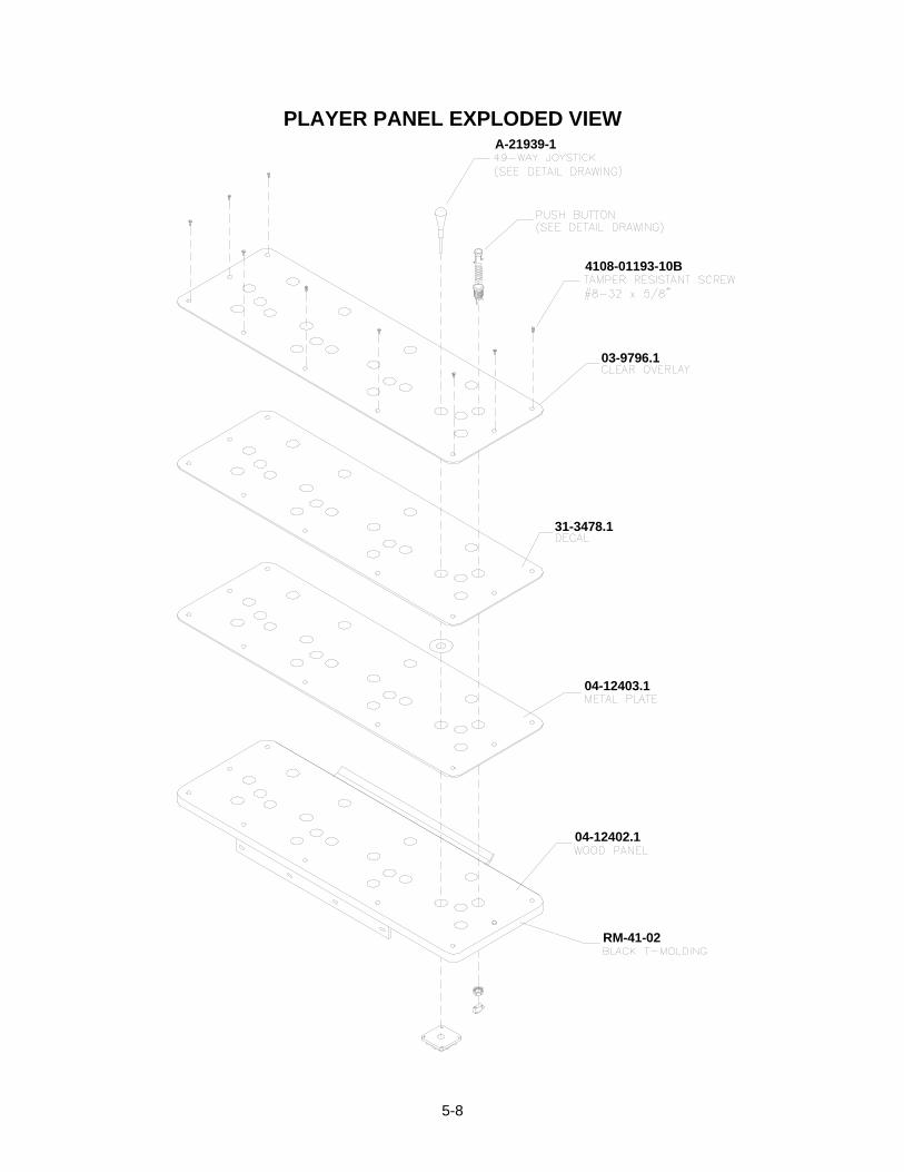
5-8
PLAYER PANEL EXPLODED VIEW
RM-41-02
03-9796.1
04-12402.1
04-12403.1
4108-01193-10B
A-21939-1
31-3478.1

5-9
COIN DOOR ASSEMBLY
CASH DOOR ASSEMBLY
03-8863
5580-13476-00

5-10
49-WAY JOYSTICK ASSEMBLY A-21939-1AND BUTTON ASSEMBLY 20-10209-X

5-11
ELECTRONICS ASSEMBLY A-23483

5-12
POWER SUPPLY 20-10167
*Note:

5-13
SOUND I/O CARD A-23431
Field Replaceable Parts
Description Location Part NumberAmplifier, 20W, TDA 7204A U19, U20 5370-14146-00
Capacitor, 2200 µF, 16V C310 5040-15904-00Capacitor, 2200 µF, 25V C254 5040-14630-00
Crystal, 4 MHz, Type HC49U Y2 5520-14602-00Crystal, 16 MHz, Type HC49U Y3 5520-14595-00Crystal, 20 MHz, 3-Lead Type Y1 5520-15159-00Heatsink, TO-220, Type 5298b U19, U20 5705-12638-00IC, TDA7240V, 20W Amplifier U19, U20 5370-14146-00
Oscillator, 33 MHZ, TTL, Tri-State U3 5521-13806-06ROM, Sound Boot U44 A-5343-45994-2
Shunt, 0.025” Square Pins Any Jumper 5882-13046-00
CPU BOARD ASSEMBLY A-23429

5-14
Field Replaceable PartsDescription Location Part Number
Capacitor, 2200 µF, 16V, Radial C24, C115, C209,C229, C294
5040-15904-00
Heatsink, TO-220, Small U5 5705-14562-00Heatsink, TO-220, Type 5298b U15 5705-12638-00
PLD, CPU Configuration U22 A-22912Regulator, CS5203a U5 5250-16015-00
ROM, Boot U27 A-5343-45994-1ROM, Expansion U28 For Future Use

5-15
BANSHEE VIDEO CARD 20-10516
No Field-Replaceable Parts

5-16
AUXILIARY ADAPTER CARD ASSEMBLY 04-12652
No Field-Replaceable Parts
I-40 BOARD ASSEMBLY 04-11089
No Field-Replaceable Parts

5-17
OTHER PARTS
Bulbs, Filters and FusesBallast, 15W..................................................................................................................................20-10481.1Bulb, #555 6.3V, 0.25A, Wedge-Based Light ....................................................................................24-8768Fuse, 1ASB, 250V ................................................................................................................. 5731-06569-00Fuse, 3ASB, 250V, 3AG........................................................................................................ 5731-10356-00Holder, 1 x 3AG, ¼” Terminal Fuse....................................................................................... 5733-15299-00Tube, Fluorescent, 15W, 18” .............................................................................................................24-8809
CablesBraid, Ground with ¼” Terminal...................................................................................................H-22327-86Cable, Coin Meter Extension............................................................................................................ H-22786Cable, Disk Drive Fan.................................................................................................................... H-22900.2Cable, IDC AC .................................................................................................................................. H-20353Cable, Main Harness (JAMMA) ..................................................................................................... H-22824.1Cable, Ribbon, 40-Pin............................................................................................................ 5795-15344-07Cable, Ribbon, 20-Pin............................................................................................................ 5795-10937-09Cable, Shielded Video .....................................................................................................................20-10493Cable, Stereo Speaker ..................................................................................................................... H-22758Cable, Fluorescent Lamp and Electronic Ballast.............................................................................. H-22507Harness, Cabinet AC........................................................................................................................ A-22693
DocumentsCard, Game Information ..................................................................................................................16-10650Manual, SportStation, 25” ........................................................................................................ 16-40094-101
Kit, Spare PartsKit, Spare Parts................................................................................................................................. A-22561
Leveler, Leg Adjustment, 3” ........................................................................................................08-7377Wrench, T-20, Long Arm Tamper-Resistant (Torx®)..................................................................20-9620
Meter, CoinMeter, 5V, 2W Coin (with Diode) ........................................................................................... 5580-13476-00

5-18
LINE CORD APPLICATION TABLE
PartNumber
Country58
50-1
3275
-00
5850
-132
71-0
0
5850
-132
72-0
0
5850
-132
73-0
0
5850
-132
76-0
0
5850
-132
77-0
0
5850
-132
78-0
0
USAUKItalyJapanNew ZealandGermanySpainDenmarkFinlandHollandNorwaySwitzerlandHungaryCanadaAustriaFranceAustraliaBelgium
TYPICAL I.E.C. LINE CORD WITH INLINE FEMALE PLUG

5-19
COIN DOOR APPLICATION TABLE
PartNumber
Country 09-9
6017
-15
09-9
6017
-17
09-9
6017
-33
09-9
6000
.1
AustraliaAustriaBelgiumCanadaDenmarkFinlandFranceGermanyHollandHungaryItalyJapanNew ZealandNorwaySpainSwitzerlandUKUSA

5-20
NOTES

6-1
SPORTSTATION TM
C H A P T E RS I X
WIRING
WARNING: Failure to reconnect ground wires or replace metal shields and covers withmounting hardware installed and properly tightened may result in radio frequency interference.

6-2
JAMMA Chart
Function Wire Color Pin Function Wire Color PinGround Black A Ground Black 1Ground Black B Ground Black 2+5VDC Red C +5VDC Red 3+5VDC Red D +5VDC Red 4-5VDC Yellow E -5VDC Yellow 5+12VDC Orange F +12VDC Orange 6Key N/C H Key N/C 7Coin Counter 2 Brown-Red J Coin Counter 1 Brown 8Not Used N/C K Not Used N/C 9Speaker -, Left Brown-Gray L Speaker +, Left Red-Gray 10Speaker -, Right Brown-White M Speaker +, Right Red-White 11Video Green Yellow-Green N Video Red Yellow-Red 12Video Sync Yellow-White P Video Blue Yellow-Blue 13Service Credits White-Gray R Video Ground Yellow-Black 14Slam Tilt Black-Green S Test Black-Blue 15Coin 2 Black-Red T Coin 1 Black-Brown 162 Start Violet-White U 1 Start White 172 Up Violet-Black V 1 Up White-Black 182 Down Violet-Brown W 1 Down White-Brown 192 Left Violet-Red X 1 Left White-Red 202 Right Violet-Orange Y 1 Right White-Orange 212 Jump Violet-Yellow Z 1 Jump White-Yellow 222 Pass Violet-Green a 1 Pass White-Green 232 Turbo Violet-Blue b 1 Turbo White-Blue 24Not Used Violet c Not Used White-Violet 25Not Used N/C d Not Used N/C 26Ground Black e -5V Ground Yellow-Brown 27Ground Black f Ground Black 28
Solder Side of Circuit Board Component Side of Circuit Board
Control Panel Wires That Aren’t Part of Main JAMMA HarnessFunction Wire Color P14- Function Wire Color P7-
4 Digital Ground Black 1 3 Digital Ground Black 1+5 Volts Red 2 Unused Not Connected 2Unused Not Connected 3/4/15 Unused Not Connected 3/4/154 Start Gray-White 5 3 Start Blue-White 64 Stick Up, Bit 0 Gray-Black 6 3 Stick Up, Bit 0 Blue-Black 74 Stick Down, Bit 1 Gray-Brown 7 3 Stick Down, Bit
1Blue-Brown 8
4 Stick Left, Bit 2 Gray-Red 8 3 Stick Left, Bit 2 Blue-Red 94 Stick Right, Bit 3 Gray-Orange 9 3 Stick Right, Bit 3 Blue-Orange 104 Button A, Jump Gray-Yellow 10 3 Button A, Jump Blue-Yellow 114 Button B, Pass Gray-Green 11 3 Button B, Pass Blue-Green 124 Button C, Turbo Gray-Blue 12 3 Button C, Turbo Blue 134 Button D (N/U) Gray-Violet 13 3 Button D (N/U) Blue-Violet 14
D.C. Power Source Voltage LimitsFunction Range Limits ID Function Range Limits ID
Digital Circuits +4.90V to +5.10V +5V Audio, Lights -4.75V to -5.25V -5VAudio, DBV +11.5V to +12.5V +12V NOTE: +5V is adjustable at the Power Supply

6-3

6-4
Power Wiring Chart

6-5
CABINET WIRING DIAGRAM
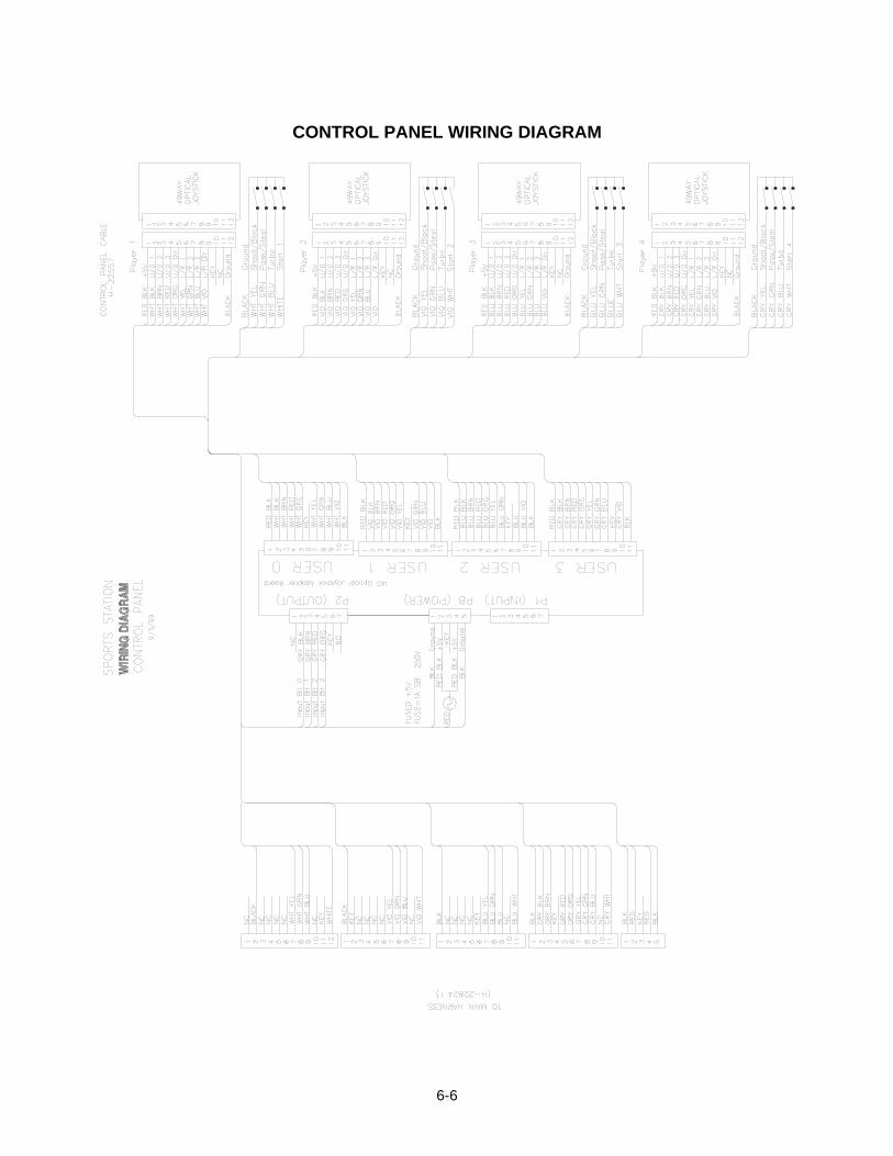
6-6
CONTROL PANEL WIRING DIAGRAM

6-7
CONTROL WIRING DIAGRAM(49-WAY JOYSTICK)
POSITION LOGIC TABLE
DIRECTION FULLYLEFT
MODERATELYLEFT
SLIGHTLYLEFT
DEADCENTER
SLIGHTLYRIGHT
MODERATELYRIGHT
FULLYRIGHT
FULLYUP
01110111(00)
01110011(01)
01110001(02)
01110000(03)
01111100(04)
01111110(05)
01111111(06)
MODERATELYUP
00110111(07)
00110011(08)
00110001(09)
00110000(10)
00111100(11)
00111110(12)
00111111(13)
SLIGHTLYUP
00010111(14)
00010011(15)
00010001(24)
00010000(24)
00011100(24)
00011110(19)
00011111(20)
DEADCENTER
00000111(21)
00000011(22)
00000001(24)
00000000(24)
00001100(24)
00001110(26)
00001111(27)
SLIGHTLYDOWN
11000111(28)
11000011(29)
11000001(24)
11000000(24)
11001100(24)
11001110(33)
11001111(34)
MODERATELYDOWN
11100111(35)
11100011(36)
11100001(37)
11100000(38)
11101100(39)
11101110(40)
11101111(41)
FULLYDOWN
11110111(42)
11110011(43)
11110001(44)
11110000(45)
11111100(46)
11111110(47)
11111111(48)
NOTE: 1. Connector pin sequence for the above data is as follows: 9 8 7 6 5 4 3 2 referred to ground at pin 12. 2. Numbers in parentheses are found in the Switch Test. Program does not use the “slightly” positions.

6-8
SOUND I/O BOARD ASSEMBLY A-23431

6-9
SOUND I/O BOARD JUMPER POSITION TABLE *
Jumper Location Function Meaning Position StateInput Mode Pins 1 & 2J1
(Note 1)Near U9 & Crystal Y3 I/O Connector P2
Output Mode Pins 2 & 3
Positive Sync Jumper NotInstalled
J2 Between U35 & U10 Video Sync
Negative Sync Pins 1 & 2
Input Mode Pins 1 & 2J3(Note 2)
Near U15 I/O Connector P4
Output Mode Pins 2 & 3
J4 None None Not Used None ---Input Mode Pins 1 & 2J5
(Note 2)Between U15 &Connector P2
I/O Connector P4
Output Mode Pins 2 & 3
J6 None None Not Used None ---J7 None None Not Used None ---
Input Mode Pins 1 & 2J8(Note 1)
Between U9 &Connector P4
I/O Connector P2
Output Mode Pins 2 & 3
Notes1. Configure I/O port P2 by setting both jumpers J1 and J8 to input or output mode.
2. Configure I/O port P4 by setting both jumpers J3 and J5 to input or output mode.

6-10
SOUND I/O BOARD LED INDICATOR STATUS TABLE
LED Location Function Color State MeaningOff --On --LED1
(Note 1)Near U11 Not Used
(Remains Off)Green
Blinking --Off Not in Use (No Game Linking)
LED2(Note 2)
Near U34 & CrystalY1
Linking ConnectorStatus
Green On Link Continuity Good
Off* No PowerLED3
(Note 2)Near the JAMMA
Connector-5V Power Indicator Red On* Normal Operation
Off No PowerLED4(Note 2)
Near U35 &Connector P14
+12V PowerIndicator
RedOn Normal OperationOff No PowerLED5
(Note 2)Near Connector
P23+5V Power Indicator Red
On Normal OperationOff Not in Use
LED6(Note 2)
Near U34 & CrystalY1
CPU Linking Activity RedOn CPU Communicating with
Ethernet ControllerOff Not in Use (No Game Linking)On Sending DataLED7
(Note 2)
Near U34 & CrystalY1
Linking TransmittingData
Red
Blinking Normal OperationOff No Sound Boot ROMOn Locked UpLED8
(Note 1)
Near U14 & CrystalY1
Audio Activity Yellow
Blinking Normal OperationOff Not in Use (No Game Linking)LED9
(Note 2)Near U34 & Crystal
Y1Linking Receiving
DataYellow
On Receiving DataOff --On --LED10
(Note 1)
Near U44 & CrystalY2 Not Used
(Remains On)
Green
Blinking --Off --On --LED11
(Note 1)
Near U44 & CrystalY2 Not Used
(Remains On)
Red
Blinking --Off --On --LED12
(Note 1)
Near U44 & CrystalY2 Not Used
(Remains On)
Yellow
Blinking --Off --On --LED13
(Note 1)
Near U44 & CrystalY2 Not Used
(Remains On)
Yellow
Blinking --
Notes1. Software controls this LED. Indications are game and revision-specific. Changing the EPROMs on this board
may alter the function of this LED. Firmware damage may also cause new of different LED behavior.
2. Hardware controls this LED. Indications depend on hard-wired circuitry. A change in normal LED behaviormay indicate a circuit fault. Changing the EPROMs on this board shouldn’t alter the function of this LED.

6-11
CPU BOARD INDICATOR AND SWITCH LOCATIONS
CPU BOARD SWITCH
Switch Location Function Positions State Meaning2 Off Normal OperationS1* Edge Near U10
and U12Resets and
Restarts Game On Forced Reset
*NotesThis switch resets the CPU Board without shutting off power at the power supply.

6-12
CPU BOARD JUMPER LOCATION TABLE
Jumper J1 J2 J3 J4 J5 J6
LocatedNear…
U28 &Connector P5
U22 & U27
CPU BOARD JUMPER POSITION TABLE
ROM Type Default Options* J1 J2 J3 J4 J5 J6
27C080, 1M X 8, EPROM 1-2 2-3 1-2 1-2 -- --
27C040, 512K x 8, EPROM 1-2 1-2 1-2 1-2 -- --
27C010, 128K x 8, EPROM 1-2 1-2 1-2 2-3 -- --
29F040, 512K x 8, Flash 2-3 1-2 2-3 1-2 -- --
29F020, 256K x 8, Flash 1-2 1-2 2-3 1-2 -- --
Boot(U27)
29F010, 128K x 8, Flash 1-2 1-2 2-3 1-2 -- --
27C080, 1M x 8, EPROM -- -- -- -- 2-3 --
27C040, 512K x 8, EPROM -- -- -- -- 1-2 --
Expansion(U28)
27C010, 128K x 8, EPROM -- -- -- -- 1-2 --
Boot from CPU ROM -- -- -- -- -- 1-2ExternalBoot
Boot from SIO ROM -- -- -- -- -- Re-moved
*Notes1. -- = Not Applicable
2. Memory type numbers shown are for blank parts. Your game requires programmed parts.

6-13
CPU BOARD LED INDICATOR STATUS TABLE
Device Location Function Color State MeaningOff Insufficient Power
On Power OKLED1 Near U6, U7 &
U163.3V CPU
PowerIndicator
Red
Blinking Power Supply Fault
Off Disk Not in Use
On Locked Up DiskLED2 Near U28 &
Connector P5Hard Disk
DriveActivity
Green
Blinking Normal Disk Activity
Off*
On*RP63 Near U22 &
U26Indicator Red
Blinking*Sequentially
See Note 3, Below.
Notes1. LED1 monitors CPU power (+3.3 volts). If his LED is off or blinking, investigate processor circuits. If other
LEDs are off or blinking at the same time, check +5-volt circuits or the game power supply.
2. LED2 flashes when the hard disk is operating during game play. LED2 may light continuously during startup.If this LED remains lighted, the hard drive may be locked up or faulty.
3. Software controls RP63. In this game, RP63 initially indicates program startup stages. This LED is a seven-segment, alphanumeric display device. Normally, RP63 displays a lowercase “b,” or an “O” pattern withsequentially blinking segments. During Self-Test screens, RP63 displays a “bouncing bar” that resembles ahyphen (“-“).

6-14
VIDEO BOARD INDICATOR AND SWITCH LOCATIONS
NoteThis video board has no jumpers or LEDs.

6-15
NOTES

7-1
SPORTSTATION TM
C H A P T E RS E V E N
TROUBLESHOOTINGNOTICE: The term VGM refers to the video game machine.
CAUTION: This VGM uses complex electronic components that are very sensitive tostatic electricity. Observe the following precautions before handling VGM electronics.Failure to do so may void your warranty and could damage electronic assemblies.
• Before servicing electronics, turn off AC power to the VGM. Wait for capacitors to discharge.• Before touching or handling electronic assemblies, discharge static electricity on your body. To
discharge this static, begin by connecting the line cord to a grounded outlet. Don’t turn on theVGM! Next, touch the safety ground stud of the power supply chassis.
• Store electronic assemblies in an anti-static area. Use anti-static bags to store or transport VGMcircuit boards. Transport the hard drive in its shipping container.
• Don’t remove or connect electronic assemblies when cabinet power is on. Otherwise, you’lldamage electronic assemblies and void the VGM warranty.
• After you complete maintenance or service, replace ground wires, shields, safety covers, etc.Install and tighten ground and mounting screws.

7-2
Coin Mechanism and Pricing Troubleshooting TableSYMPTOM CAUSE REQUIRED ACTION
Improper settings atPricing Menu
From Coin Options Menu, choose PRICINGOPTIONS MENU. Verify that units and creditsare set correctly.
Incorrect pulse widthon bill validators
1. Consult bill validator manufacturer’s literature.Adjust pulse width on validator to long setting.
2. Retest validator operation.
Faulty wiring1. Check that cabinet wiring is correct for this VGM.2. Assure that coin meter and coin switches
connect properly to control input wires.
• VGM (video game machine)accepts currency or tokens,but number of credits percoin or bill is incorrect.
Faulty coinmechanism
1. Verify that coin mechanism works correctly bytesting it in working VGM.
2. If mechanism is bad, replace it.
Improper currency1. Unlock and open cash door. Empty cash box.
Inspect revenue for counterfeit currency.2. Check vault. Remove any items that block path
from mechanism.
Faulty coinmechanism
1. Unlock and open coin door. Check eachmechanism for proper mounting.
2. Remove mechanism.3. Clear currency path.4. Reinstall mechanism and latch it.5. Enter Menu System by pressing and holding
TEST MODE switch inside coin door. From MainMenu, choose CONTROLS TEST. Use tests toconfirm operation of coin switches.
• VGM won’t accept currencyor tokens.
• VGM won’t start.
• Audio and video are present.
Tilted coinmechanism or VGM
1. Verify that mechanism is level after doors close.2. Repair or replace coin door if it is bent or
damaged.3. If necessary, adjust cabinet leg levelers to keep
mechanisms vertical.Burned-out bulb 1. Burned-out bulbs may appear white or darkened.
Check continuity with DVM.2. Replace burned-out bulb with same type.
• Coin indicators don’t light
Open fuse circuit 1. Check fuse continuity with DVM.2. If fuse is blown, replace fuse with same type.3. If fuse isn’t blown, check wiring.
CAUTION: Don’t remove or install any connector when power is turned on. Installationunder power will damage the circuit boards or hard disk drive and void the warranty.
Typical Coin Mechanism Mounting

7-3
VGM Startup Troubleshooting TableSYMPTOM CAUSE REQUIRED ACTION
Power problem1. Check that VGM power switch is on.2. Inspect electronics to see if fans are turning. If
not: Is power supply connected to its powercable? Is power supply turned on?
3. Plug VGM into AC power outlet. Verify presenceof AC line voltage.
Improper line voltageswitch setting
Turn off VGM power. Unplug AC line cord. Checkline voltage switch. If necessary, set it to agreewith local AC line voltage. Retest VGM.
Open fuse1. Turn off VGM power. Examine AC fuse on power
supply.2. Examine DC fuses inside coin door vault.3. Replace faulty fuses with identically rated parts.4. Turn on VGM power. If fuse opens again, check
DC wiring harness and connectors.
Faulty wiring1. Remove line cord. Test line cord, power plug,
and IEC connector for breaks or damage. Verifycontinuity of each wire in cord. Install cord atpower chassis. Press connector firmly to seat it.
2. Check other cables in same manner.3. Assure that cabinet wiring harness connectors
fully seat in corresponding power supply andboard connectors.
4. Inspect wiring for breaks or damage.
• VGM (video game machine)doesn’t start.
• VGM appears completelynon-functional.
• No audio
• No illumination
• No video display
Faulty circuit boardsTurn off power for one minute and turn VGM onagain. Power On Self-Test checks electronics.
Typical Location of Power Supply and Line Cord

7-4
VGM Startup Troubleshooting Table, continuedSYMPTOM CAUSE REQUIRED ACTION
Power problem1. Inspect circuit boards under low-light conditions.
LEDs glow if processor circuits receive voltage.Fan should be turning. These indications provepresence of DC from power supply. Still,voltages or signals may not be normal.
2. Turn on VGM power. Using 20-volt DC setting ondigital voltmeter, measure DC voltages at powerconnector pins.
3. Using 2-volt AC setting on digital voltmeter,measure same DC voltages as above. Anyreading indicates ripple or noise. In that case,service power supply.
Faulty wiringTurn off VGM power. Assure that wiring harnessconnectors attach and fully seat onto matingboard connectors.
Improper jumper orDIP switch settings
Verify that circuit board jumpers are set asintended. Check DIP switch settings.
• VGM (video game machine)appears non-functional.
• Currency acceptor priceindicator is illuminated.
Faulty circuit boardsRun power-up self-test sequence. Note errors orfailures during tests. Compare LEDs with LEDindicator status charts. Note discrepancies.
CAUTION: Don’t remove or install any connector while power is turned on. Doing sowill damage circuit boards or hard disk drive, and void warranty.
Front View Of Coin Door Interior View Of Electronics

7-5
VGM Startup Troubleshooting Table, continuedSYMPTOM CAUSE REQUIRED ACTION
Faulty coinmechanism
1. Unlock and open coin door. Check eachcurrency acceptor to assure proper mounting.Verify that each release latch is closed andlocked. Does mechanism accept and rejectcurrency correctly? Test mechanism with goodand bad coins.
2. Inspect to see if external acceptor indicators(Pricing, Flashing Arrows, etc.) are lit.
3. Verify that each acceptor operates properly byplacing it in working VGM. Replace bad parts.
Faulty switches1. Enter Menu System by pressing and holding
TEST MODE switch inside coin door. From MainMenu, choose CONTROLS TEST. Use tests toconfirm operation of each switch.
2. Assure that no loose parts or wires are caught inswitch contacts.
3. Check for continuity in each suspect switchconnection (Common to Normally Open orCommon to Normally Closed).
4. Replace faulty switches (bent levers, brokenactuators, etc.).
• VGM (video game machine)doesn’t start.
• VGM accepts currency ortokens.
• Audio and video are present.
Faulty wiring1. Assure that no wires are caught in hinges,
latches or switch contacts.2. Check wiring continuity from circuit board
connectors to acceptors.
Interior View of Coin Door and Cash Door

7-6
Audio Troubleshooting TableSYMPTOM CAUSE REQUIRED ACTION
Improper volumesetting
1. From Main Menu, choose VOLUME LEVEL.Check that Attract Music is on (enabled). Verifythat all volume levels are set well above zero.
2. If necessary, change levels to make VGMaudible.
• No audio
• Video is present
• VGM (video game machine)appears to operate normally Faulty SIO Board
1. From Main Menu, enter Diagnostics Menu.Select SOUND SUBSYSTEM TEST. Testchecks entire sound system.
2. Run power-up self-test sequence. Note errorsthat VGM finds during tests. Compare Sound I/OBoard (SIO) LEDs with LED indicator statuscharts. Note discrepancies.
3. Verify proper operation of SIO Board by placing itin working VGM.
4. If board is faulty, replace it.
Faulty wiring1. Check that cabinet wiring is correct for this VGM.2. Verify that cabinet wiring provides separate wires
(not common return) for each speaker.3. Check connection of all cabinet ground wires.
• Constant low hum from allspeakers.
Faulty power supplyUsing 2 Volt AC setting on digital voltmeter,measure voltages at speaker terminals. Anyreading indicates ripple or noise. In that case,service power supply.
Faulty or improperspeaker
1. Turn off VGM power. Remove grilles and checkspeakers. Assure that speakers are full range(100 to 10,000 Hz response) and rated for atleast 20 watts. Woofers must be rated for at least40 watts.
2. Verify proper speaker operation by connectingspeaker in question to working VGM.
3. If speaker is faulty, replace it.
• Audio is distorted, muffled orhas missing frequencies.
Faulty wiringMultiple-speaker installations: Check forreversed wires at one speaker. Weak lowfrequencies and thin or hollow sound quality issymptom of incorrectly phased speakers. Soundtests may not detect this condition, but you canhear it during VGM operation.
Faulty speaker1. From Main Menu, choose SOUND TEST.
Recheck speakers with audio signals providedby test.
2. Verify proper speaker operation by connectingspeaker in question to working VGM.
3. If speaker is faulty, replace it.
Faulty circuit board1. From Main Menu, enter Diagnostics Menu.
Select SOUND SUBSYSTEM TEST. Testchecks entire sound system.
2. Run power-up self-test sequence. Note errorsthat VGM finds during tests. Compare circuitboard LEDs with LED indicator status charts.Note discrepancies.
3. Verify SIO Board operation by connecting boardto working VGM.
4. If board is faulty, replace it.
• Dead sound channel
Faulty wiringVerify that cabinet wiring is correct. Assure thatall speakers connect to audio wires. Check forbroken or shorted wires.

7-7
Joystick Troubleshooting TableSYMPTOM CAUSE REQUIRED ACTION
Faulty switchEnter game Menu System by pressing andholding TEST MODE switch inside coin door.From Diagnostics Menu, choose SWITCH TEST.Operate joystick in question. Check for properreadings of up, down, left and right.
Faulty switch wiring1. Check for wires caught in door hinges, latches or
switch contacts.2. Verify that harness connectors are attached and
fully seated.3. Assure that joystick switches connector properly
to control input wires.4. Check joystick cable ground connections.5. Check that cabinet wiring is correct for this VGM
(video game machine).
Faulty mechanicalparts
1. Inspect joystick for: Missing, loose or damagedparts, torn rubber T-band, etc.
2. Replace bad parts.
Dirty optosClean dust out of optos with swab and cleaner.Don’t apply cleaner directly into opto. Never usesolvents!
Faulty joystick fuseCheck fuses on I-40 Joystick Interface Boardinside player control panel. Each joystick has itsown fuse.
Faulty joystickelectronics
1. If joystick fuses are okay, install joystick inworking VGM (video game machine) and retestit.
2. If joystick still doesn’t work, replace it.
• Players complain thatjoystick operates erraticallyor unreliably
• Game starts normally
Faulty I-40 JoystickInterface Board
1. If joystick works in second VGM, I-40 JoystickInterface Board may be bad.
2. Replace board and retest joystick.
Joystick Parts

7-8
Video Troubleshooting TableSYMPTOM CAUSE REQUIRED ACTION
Power problemVerify connection of AC Power to video monitor.Inspect CRT neck in dim light. Glowing filamentnear CRT base proves that some monitorcircuits receive power. Still, voltages or signalsmay not be normal.
Faulty wiring1. Turn off VGM power. Verify that video signal and
Remote Adjustment Board connectors seatproperly on Video Monitor Board.
2. Assure that video cables connect to circuitboards.
3. Assure that no wires are caught on chassis ormounting brackets.
Improper monitoradjustments
Check that BRIGHTNESS (intensity) andCONTRAST are set above their minimumlevels.
• Monitor appears non-functional
• Audio is present
• VGM (video game machine)controls operate normally
Faulty monitorcircuitry
1. Examine AC line fuse on Video Monitor Board. Iffuse is faulty, replace it with identical fuse.
2. If fuse is good: Verify that video monitor operatescorrectly by placing it in working VGM.
3. If monitor is bad: Check monitor power supply.4. If power supply is good: Check monitor
horizontal output transistor and related circuitry.
WARNING: HIGH VOLTAGE. VGM monitors generate and store potentially lethal highvoltages. Avoid touching any part of the monitor until power has been off for sometime. A picture tube can maintain a hazardous charge for up to several days. Onlyqualified technicians should service monitors. Turn off the power, unplug the VGM anddischarge the CRT before attempting service. Even properly discharged tubes canrevert to a highly charged state, without reapplication of power.
WARNING: In normal operation, the monitor doesn’t require isolation from AC linevoltage. During bench servicing, you may need to operate the monitor outside thecabinet. If you do, isolate the monitor from line voltage with an isolation transformer.
CAUTION: Don’t operate the monitor without the Remote Adjustment Board.
Typical Cutaway Rear View

7-9
Video Troubleshooting Table, continuedSYMPTOM CAUSE REQUIRED ACTION
Improper components1. Verify that hard disk drive is correct for this VGM
(video game machine). Label on drive recordsmanufacturer name, assembly number andprogram version.
2. Verify that circuit boards are correct for thisVGM. Label on each board records manufacturername, assembly number and hardware version.
3. Verify that ROM instruction set is correct for thisVGM. VGM set only has one ROM. Label onROM records assembly number and softwareversion.
• Game screens don’t appear
• No audio
• Power-up self-test runs
Hard drive problems1. Turn VGM on. Immediately look under hard
drive. Hard Drive Activity LED flashes if drive isoperating properly.
2. Allow VGM to load normally. Note and recordany error messages that occur during self-test.
3. Remove hard drive and install it in working VGM.If symptom recurs there, hard drive is faulty.Replace it.
• Blotches of color appear onscreen
Picture tube aperturemask is magnetized
Remove diskettes from room. Demagnetizemonitor with external degaussing coil. Take carenot to magnetize neighboring VGMs. Monitormay be on or off for this procedure.
• White areas in center ofscreen appear tinged withcolor
• Object edges have fringe ofone or more colors
Picture tube purity orstatic convergence isout of alignment
1. Turn on VGM (video game machine).2. Press and hold TEST MODE to enter Menu
System. At Main Menu, select Monitor TestsMenu. Run through Crosshatch, Red, Green andBlue screens to find clearest display of problem.
3. Display screen with greatest problem.4. Display Crosshatch Screen. Locate purity and
static convergence ring magnets on back ofmonitor neck. Watch screen in mirror. Adjustmagnets to minimize problem. Followinstructions from monitor manufacturer.
5. Display Crosshatch Screen. Touch upadjustments while watching screen in mirror.
• Background of Attract Modescreens seems out of sync
• Words on screen read OK
Someone set DIPswitch for resolutionlower than VGA
1. VGM only outputs VGA video. Press and holdTEST MODE to enter Menu System. At MainMenu, select DIP Switch Test Menu.
2. Locate DIP switch bank U12 on the Sound I/OBoard.
3. Turn off switch 2.4. Reenter Attract Mode and check screens.
CAUTION: Don’t operate the monitor without its Remote Adjustment Board.
WARNING: HANDLE FLUORESCENT TUBE AND CRT WITH CARE. If you drop afluorescent tube or CRT and it breaks, it will implode! Shattered glass can fly eight feetor more from the implosion.

7-10
Video Troubleshooting Table, continuedSYMPTOM CAUSE REQUIRED ACTION
• White areas at screen edgesappear tinged with color
• Dots at screen edges appearoval or cylindrical
Picture tube dynamicconvergence is out ofalignment
Have service bureau dynamically reconvergemonitor. This procedure requires removing andrepositioning yoke. Service bureau must followinstructions from monitor manufacturer.
Faulty wiring1. Check connectors and cables for wiring
continuity. Video cables connect graphics card tocircuit boards, and then to video monitor.
2. Assure connection of all cabinet ground wires,especially at video monitor chassis.
Faulty monitorcircuitry
1. Check video monitor operation by connecting itto working VGM (video game machine).
2. Assure that video monitor is correct type for thisVGM. Video monitors with wrong resolution can’tlock sync.
Improper sync signals1. Check to see if Video Board puts out type of
sync that your monitor requires.2. Verify that jumpers are set correctly for monitor.3. If necessary, add or remove video sync jumper
at Sound I/O Board jumper block J10. With nopins connected (or pins 2 and 3 connected),board outputs positive sync. With pins 1 and 2connected, board outputs negative sync.
• Video tears or rolls, or hasblack bar down middle ofscreen
Electromagnetic fields Move cabinet far away from machines,appliances, or competitors’ VGMs.
Faulty wiringCheck connectors and cables for wiringcontinuity from circuit boards to video monitor.
• Missing colors
Faulty monitor colordrive circuitry
Verify that video monitor operates correctly byconnecting it to working VGM.
• One color is dimmer orbrighter than others
• Whites appear tintedeverywhere on screen
Maladjusted colorbias pots
1. Turn on VGM (video game machine).2. Enter Monitor Tests Menu.3. Watch Color Bars screen in mirror.4. Adjust three bias pots for best colors. (Most
monitor neck boards include these pots.)5. Also check White Screen. Touch up controls.6. If whites still seem tinted, have service bureau
rejuvenate picture tube.
• Picture is dim or faded MaladjustedBRIGHTNESS pot orsubnormal picturetube emission
1. Watch Color Bars screen. Adjust BRIGHTNESSand CONTRAST pots for greatest number ofgrays. You’ll find these pots on Monitor RemoteControl Board, behind coin door.
2. If pots have no effect, have service bureaurejuvenate picture tube.
• Picture is too narrow Maladjusted WIDTHpot
Enter Monitor Tests Menu. Watch CrosshatchScreen while adjusting WIDTH pot for bestpicture. You’ll find this pot on Monitor RemoteControl Board, behind coin door.
• Picture is too short Maladjusted HEIGHTpot or damagedvertical circuit
1. Enter Monitor Tests Menu. Watch CrosshatchScreen while adjusting HEIGHT pot for bestpicture. You’ll find this pot on Monitor RemoteControl Board, behind coin door.
2. If pot has no effect, service vertical output circuit.
• Picture seems shifted to oneside
MaladjustedHORIZONTALPOSITION pot
Enter Monitor Tests Menu. Watch CrosshatchScreen while adjusting HORIZONTAL POSITIONpot for best picture. You’ll find this pot on MonitorRemote Control Board, behind coin door.
• Keystone-shaped picture Shorted turns in yoke1. Substitute working yoke.2. Have service bureau converge monitor.3. Retest monitor.

7-11
Software Update Troubleshooting TableSYMPTOM CAUSE REQUIRED ACTION
You skipped steps orperformed them outof sequence.
Return update components to kit, reinstalloriginal parts in cabinet, and try process again.• Update didn’t work
• After update procedure,screen reports lower thanlatest version
Installation error mayhave damageddevice.
1. Inspect for bent or broken pins.2. If you have another kit, try it.3. Ask your distributor to check your floppy disk.
Mismatched bootupdate version andhard drive.
Once you’ve updated disk drive, CPUinstructions must be at correct version to makeuse of new data stored on disk. Be certain thatboot ROM device resides in proper socket.
• No Attract Mode screens
• Board indicators illuminate,but screen is completelyblank You may have
installed devices inwrong sockets.
1. Install disk ROM. Only use upgrade socket forhard disk drive updates. During game play,upgrade socket must be empty.
2. Load ROM contents onto drive.3. Remove ROM from game.
NOTICE: Someday, software updates for your VGM (video game machine) mightbecome available. These upgrades may improve your VGM’s performance or add newVGM features. Such upgrades tend to appear sometime after factory first releasesVGM. Contact your distributor for information about updates.

7-12
Miscellaneous Problem Troubleshooting TableSYMPTOM CAUSE REQUIRED ACTION
Faulty fluorescenttube
1. Remove fluorescent tube from its sockets. If youfind cracks or darkened ends, install new lamp.Clean tube.
2. Check continuity of both fluorescent tubefilaments.
3. Verify that fluorescent tube operates by placing itin working VGM.
Faulty lamp fixture 1. Verify that lamp pins make good connection withsocket contacts.
2. Check ballast for continuity.
• Marquee lamp is intermittentor non-functional
• VGM (video game machine)starts and plays normally
Faulty wiring 1. Measure fluorescent lamp AC voltages. Checkwiring and connector continuity from AC powerchassis to lamp assembly.
2. If you find faulty wiring, repair or replace it.
Obstructed fan1. Check bottom and rear of cabinet for blocked
airflow.2. Move VGM away from sources of heat.3. Turn off VGM power. Remove dust from vent
holes with high-power vacuum cleaner.Faulty wiring 1. Check fan wiring and connectors.
2. If you find faulty wiring, repair or replace it.
• VGM operates normally
• Cabinet becomes warm afterseveral hours of use
Faulty fan 1. Check operation of all fans, including powersupply fan.
2. If fan is faulty, replace it.
• Error messages appear onscreen
Faulty hardware1. Check any assembly (RAM, ROM, Battery, etc.)
identified in error messages.2. Call your authorized distributor for help with
unresolved screen messages.
Fan Location and Mounting


WARNINGS & NOTICESWARNING• Use of non-Midway parts or circuit modifications may cause serious injury or equipment damage!• Use only Midway authorized components and parts. Failure to do so will void your warranty and may result in
incorrect or unsafe operation. Substitute parts or modifications may void the EMC directive or FCC typeacceptance.
• Federal copyright, trademark and patent laws protect this game. Unauthorized modifications may be illegal underFederal law. The modification ban also applies to Midway Games Inc. game logos, designs, publications andassemblies. Moreover, facsimiles of Midway equipment (or any feature thereof) may be illegal under federal law,regardless of whether or not such facsimiles are manufactured with Midway Games Inc. components.
WARNINGPrevent shock hazard and assure proper game operation. Plug this game into a properly grounded outlet. Do not usea cheater plug to defeat the power cord's grounding pin. Do not cut off the ground pin.
WARNINGA small portion of the population has a condition which may cause epileptic seizures or momentary loss ofconsciousness when viewing certain kinds of flashing lights or patterns that are present in our daily environment.These persons may experience seizures while watching some kinds of television pictures or playing certain videogames. People who have not had seizures may nonetheless have an undetected epileptic condition.
If you or anyone in your family has experienced symptoms linked to an epileptic condition (e.g. seizures or loss ofawareness), consult your physician before using video games.
We recommend that parents observe their children while they play video games. If you or your child experience thefollowing symptoms: dizziness, altered vision, eye or muscle twitching, involuntary movements, loss of awareness,disorientation, or convulsions, discontinue use immediately and consult your physician.
NOTICEThis video game machine has been tested. It complies with limits for a Class A digital device, under FCC Rules, Part15. These limits provide reasonable protection against harmful interference when the equipment operates in acommercial environment. This equipment generates, uses and can radiate radio frequency energy. If not installed andused according to the instruction manual, this equipment may cause harmful interference to radio communications.Operation of this equipment in a residential area is likely to cause harmful interference. If interference occurs, theuser must correct it at his own expense.
NOTICEWhen Midway Games Inc. ships a game, it complies with FCC regulations. Your FCC label is proof of compliance.Legal repercussions to the owner or distributor may result if the label is missing or damaged. If your game does notcontain an FCC compliance label, call Midway Games Inc. immediately.
NOTICEYou may not reproduce any part of this publication by mechanical, photographic, or electronic means. You may notprepare phonograph recordings of this document. You may not transmit this publication or otherwise copy it for publicor private use, without permission from the publisher.
COPYRIGHT & TRADEMARK NOTICEEntire contents of this manual copyright © 1999 Midway Games Inc. All rights reserved. The following are trademarksof Midway Games Inc.: Midway®, SportStation™, NBA Showtime™, NFL Blitz 2000 Gold Edition™. ©1999 NBA.©1999 NFLP. Team names and logos are trademarks of indicated teams. The NBA logo is a trademark of theNational Basketball Association. Officially Licensed Product of the National Basketball Association. The NFL shield,Super Bowl and Pro Bowl are trademarks of the National Football League Players. The Players Inc. logo is aregistered trademark of the NFL Players.
FOR SERVICECall your Authorized Midway Games Inc. Distributor.
MIDWAY GAMES INC., 3401 N. CALIFORNIA AVE., CHICAGO, ILLINOIS 60618-5899 USA