Embed Size (px)
DESCRIPTION
hybrid system project report
Citation preview
7/18/2019 4-Report (1)
http://slidepdf.com/reader/full/4-report-1 1/21
CHAPTER 1
INTRODUCTION
In all over the world a major portion of petroleum products are used for
automobile industry. More than 95% of automobile industry is working with
petroleum products and the rest are using hybrid and electric vehicles. Among 5
years we will face a high deficiency in petroleum products. !ue to this reason
there is a demand of saving this product for the ne"t generation. It is impossible to
the sudden replacement of petroleum products so we must want to reduce the
usage of petroleum products by introducing alternative methods. A substitution for
this is to use electric energy. #he electric vehicles have comparatively less power$
high maintenance cost and high initial cost etc this problem can be eliminated
by driving the power from both the electric motor and the engine using various
coupling methods. &ence a suitable alternative can be implemented. 'o we are
introducing a new system to overcome this problem

7/18/2019 4-Report (1)
http://slidepdf.com/reader/full/4-report-1 2/21
CHAPTER 2
BLOCK DIAGRAM
(ig.).* +lock !iagram
2.1. BLOCK DIAGRAM DESCRIPTION
2.1.1 Carburetor
#he carburetor has two swiveling valves above and below the venturi. At the
top$ there,s a valve called the choke that regulates how much air can flow in. If the
choke is closed$ less air flows down through the pipe and the venturi sucks in
more fuel$ so the engine gets a fuel-rich mi"ture.
7/18/2019 4-Report (1)
http://slidepdf.com/reader/full/4-report-1 3/21
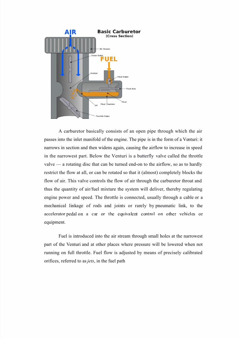
A carburetor basically consists of an open pipe through which the air
passes into the inlet manifold of the engine. #he pipe is in the form of a enturi/ it
narrows in section and then widens again$ causing the airflow to increase in speed
in the narrowest part. +elow the enturi is a butterfly valve called the throttle
valve 0 a rotating disc that can be turned end-on to the airflow$ so as to hardly
restrict the flow at all$ or can be rotated so that it 1almost2 completely blocks the
flow of air. #his valve controls the flow of air through the carburetor throat and
thus the 3uantity of air4fuel mi"ture the system will deliver$ thereby regulating
engine power and speed. #he throttle is connected$ usually through a cable or a
mechanical linkage of rods and joints or rarely by pneumatic link $ to the
accelerator pedal on a car or the e3uivalent control on other vehicles or
e3uipment.
(uel is introduced into the air stream through small holes at the narrowest part of the enturi and at other places where pressure will be lowered when not
running on full throttle. (uel flow is adjusted by means of precisely calibrated
orifices$ referred to as jets$ in the fuel path
7/18/2019 4-Report (1)
http://slidepdf.com/reader/full/4-report-1 4/21
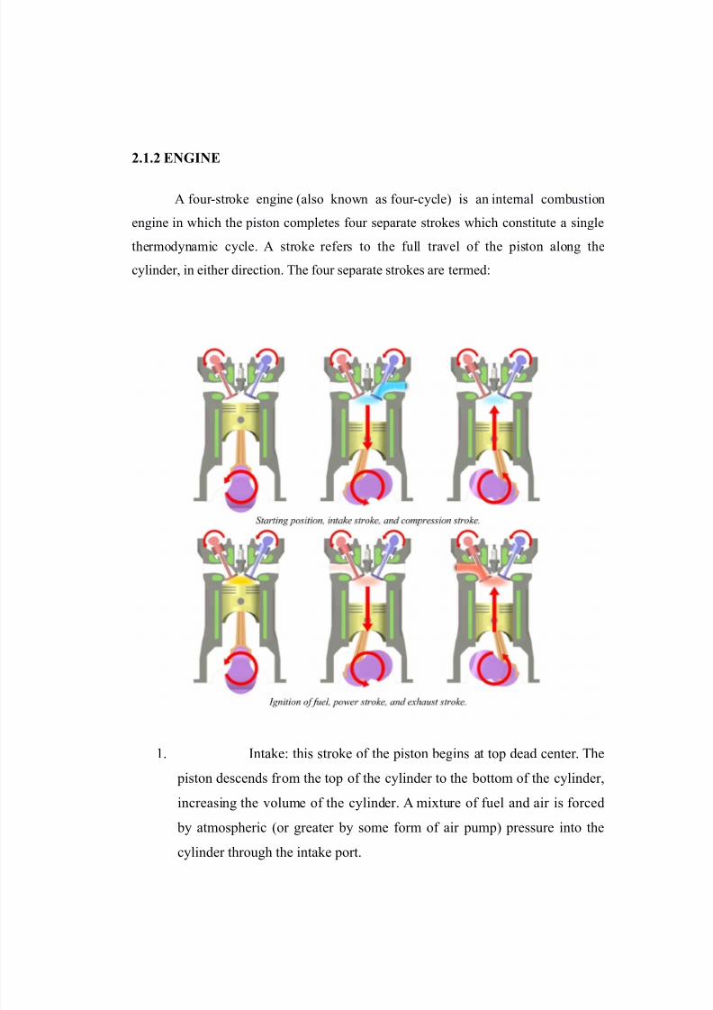
2.1.2 ENGINE
A four-stroke engine 1also known as four-cycle2 is an internal combustion
engine in which the piston completes four separate strokes which constitute a single
thermodynamic cycle. A stroke refers to the full travel of the piston along the
cylinder$ in either direction. #he four separate strokes are termed/
*. Intake/ this stroke of the piston begins at top dead center. #he
piston descends from the top of the cylinder to the bottom of the cylinder$
increasing the volume of the cylinder. A mi"ture of fuel and air is forced
by atmospheric 1or greater by some form of air pump2 pressure into the
cylinder through the intake port.

7/18/2019 4-Report (1)
http://slidepdf.com/reader/full/4-report-1 5/21
). ompression/ with both intake and e"haust valves closed$ the
piston returns to the top of the cylinder compressing the air or fuel-air
mi"ture into the cylinder head.
6. 7ower/ this is the start of the second revolution of the cycle.
8hile the piston is close to #op !ead entre$ the compressed airfuel
mi"ture in a gasoline engine is ignited$ by a spark plug in gasoline
engines$ or which ignites due to the heat generated by compression in a
diesel engine. #he resulting pressure from the combustion of the
compressed fuel-air mi"ture forces the piston back down toward bottom
dead centre.
:. ;"haust/ during the exhaust stroke$ the piston once again
returns to top dead centre while the e"haust valve is open. #his action
e"pels the spent fuel-air mi"ture through the e"haust valve1s2.
2.1.3 GEAR BOX
A gearbo" is a mechanical method of transferring energy from one device
to another and is used to increase tor3ue while reducing speed. #or3ue is the
power generated through the bending or twisting of a solid material. #his term is
often used interchangeably with transmission.
2.1. GEAR INDICATORS

7/18/2019 4-Report (1)
http://slidepdf.com/reader/full/4-report-1 6/21
2.1.! ALTERNATOR
A conductor moving relative to a magnetic field develops an electromotive
force 1;M(2 in it$ 1(araday,s <aw2. #his emf reverses its polarity when it moves
under magnetic poles of opposite polarity. #ypically$ a rotating magnet$ called
the rotor turns within a stationary set of conductors wound in coils on an iron core$
called the stator . #he field cuts across the conductors$ generating an induced ;M(
1electromotive force2$ as the mechanical input causes the rotor to turn.
#he rotating magnetic field induces an A voltage in the stator windings.
'ince the currents in the stator windings vary in step with the position of the rotor$ an
alternator is a synchronous generator.=)>
#he rotor,s magnetic field may be produced by permanent magnets$ or by a
field coil electromagnet. Automotive alternators use a rotor winding which allows
control of the alternator,s generated voltage by varying the current in the rotor field
winding. 7ermanent magnet machines avoid the loss due to magneti?ing current in the
rotor$ but are restricted in si?e$ due to the cost of the magnet material. 'ince the
permanent magnet field is constant$ the terminal voltage varies directly with the speed
of the generator. +rushless A generators are usually larger machines than those used
in automotive applications.
An automatic voltage control device controls the field current to keep output
voltage constant. If the output voltage from the stationary armature coils drops due to
an increase in demand$ more current is fed into the rotating field coils through

7/18/2019 4-Report (1)
http://slidepdf.com/reader/full/4-report-1 7/21
the voltage regulator 1@2. #his increases the magnetic field around the field coils
which induces a greater voltage in the armature coils. #hus$ the output voltage is
brought back up to its original value.
Alternators used in central power stations also control the field current to
regulate reactive power and to help stabili?e the power system against the effects of
momentary faults. ften there are three sets of stator windings$ physically offset so
that the rotating magnetic field produces a three phase current$ displaced by one-third
of a period with respect to each other.

7/18/2019 4-Report (1)
http://slidepdf.com/reader/full/4-report-1 8/21
CHAPTER 3

7/18/2019 4-Report (1)
http://slidepdf.com/reader/full/4-report-1 9/21
CIRCUIT DIAGRAM
(ig.6.* ircuit diagram
3.1 CIRCUIT DIAGRAM EXPLANATION
3.1.1 "ORKING O# CIRCUIT$
#he motor and engine crank shaft are connected using chain or gear drives.
A relay is provided on the supply to the spark plug and a petrol solenoid valve is
connected before and after the carburetor and a relay is connected to the supply to
the motor supply
n the city mode of driving when first gear is shifted then the gear
indicator will a signal corresponding to the first gear. +y using this signal the relay

7/18/2019 4-Report (1)
http://slidepdf.com/reader/full/4-report-1 10/21
connected to the motor is energi?ed and motor gets turned on and the motor is
drives the vehicle. n this time the engine is decompressed.
CHAPTER
COMPONENT STUD%
.1 RELA%
A relay is an electrically operated switch. Many relays use an
electromagnet to mechanically operate a switch$ but other operating principles are
also used.
(ig.:.5 '7!# @elay
@elays are used where it is necessary to control a circuit by a low power
signal$ or where several circuits must be controlled by one signal. In our system
we use a *) '7!# @elay.
.2.1 SPDT RELA%

7/18/2019 4-Report (1)
http://slidepdf.com/reader/full/4-report-1 11/21
A single pole double throw relay is an electromagnetic switch. It consists
of a coil$ one common terminal$ one normally closed terminal and one normally
open terminal.
8hen the coil of an '7!# relay is at rest i.e not energi?ed the common
terminal and normally closed terminal have continuity. 8hen the coil is energi?ed$
the common terminal and normally open terminal will have continuity.
SPDT RELA% AT REST SPDT RELA% "ITHCOILENERGISED
(ig.:.B 8orking of '7!# @elay
#he diagram above in the left side of the figure shows an '7!# relay at
rest$ with the coil not energi?ed. #he second diagram in figure shows the relay
with coil energi?ed. #he coil is an electromagnet that causes the arm that is always
connected to the common terminal to pivot when the coil is energi?ed$ whereby
contact is broken from the normally closed terminal and made with normally open
terminal.
8hen energi?ing the coil of the relay$ polarity of the coil does not matter
unless there is a diode across the coil. If a diode is not present$ a positive voltage
can be attached to either terminal of the coil and negative voltage to other$
otherwise you must connect positive to the side of the coil that the cathode side of
the diode is connected and negative side of the coil that the anode of the diode is
connected.
.3 PETROL SOLINOID

7/18/2019 4-Report (1)
http://slidepdf.com/reader/full/4-report-1 12/21
.3.1 GENERAL DESCRIPTION
A solenoid valve is an electromechanically operated valve. #he valve is
controlled by an electric current through a solenoid/ in the case of a two-port valve
the flow is switched on or offC in the case of a three-port valve$ the outflow is
switched between the two outlet ports. Multiple solenoid valves can be placed
together on a manifold.
'olenoid valves are the most fre3uently used control elements in fluidics.
#heir tasks are to shut off$ release$ dose$ distribute or mi" fluids. #hey are found
in many application areas. 'olenoids offer fast and safe switching$ high reliability$
long service life$ good medium compatibility of the materials used$ low control power and compact design.
+esides the plunger-type actuator which is used most fre3uently$ pivoted-
armature actuators and rocker actuators are also used.
.3.2 "ORKING O# PETROL SOLINOID
8hile there are multiple design variants$ the following is a detailed
breakdown of a typical solenoid valve design.
A solenoid valve has two main parts/ the solenoid and the valve. #he
solenoid converts electrical energy into mechanical energy which$ in turn$ opens
or closes the valve mechanically. A direct acting valve has only a small flow
circuit$ shown within section ; of this diagram 1this section is mentioned below as
a pilot valve2. In this e"ample$ a diaphragm piloted valve multiplies this small
pilot flow$ by using it to control the flow through a much larger orifice.
'olenoid valves may use metal seals or rubber seals$ and may also have
electrical interfaces to allow for easy control. A spring may be used to hold the
valve opened 1normally open2 or closed 1normally closed2 while the valve is not
activated.

7/18/2019 4-Report (1)
http://slidepdf.com/reader/full/4-report-1 13/21
#he diagram to the right shows the design of a basic valve$ controlling the
flow of water in this e"ample. At the top figure is the valve in its closed state. #he
water under pressure enters at A. + is an elastic diaphragm and above it is a weak
spring pushing it down. #he diaphragm has a pinhole through its center which
allows a very small amount of water to flow through it. #his water fills the
cavity on the other side of the diaphragm so that pressure is e3ual on both sidesof the diaphragm$ however the compressed spring supplies a net downward force.
#he spring is weak and is only able to close the inlet because water pressure is
e3uali?ed on both sides of the diaphragm.
nce the diaphragm closes the valve$ the pressure on the outlet side of its bottom
is reduced$ and the greater pressure above holds it even more firmly closed. #hus$
the spring is irrelevant to holding the valve closed.

7/18/2019 4-Report (1)
http://slidepdf.com/reader/full/4-report-1 14/21
#he above all works because the small drain passage ! was blocked by a
pin which is the armature of the solenoid; and which is pushed down by a spring.
If current is passed through the solenoid$ the pin is withdrawn via magnetic force$
and the water in chamber C drains out the passage D faster than the pinhole can
refill it. #he pressure in chamber drops and the incoming pressure lifts the
diaphragm$ thus opening the main valve. 8ater now flows directly from A to (.
8hen the solenoid is again deactivated and the passage ! is closed again$
the spring needs very little force to push the diaphragm down again and the main
valve closes. In practice there is often no separate springC the elastomer diaphragm
is molded so that it functions as its own spring$ preferring to be in the closed
shape.
(rom this e"planation it can be seen that this type of valve relies on a
differential of pressure between input and output as the pressure at the input must
always be greater than the pressure at the output for it to work. 'hould the
pressure at the output$ for any reason$ rise above that of the input then the valve
would open regardless of the state of the solenoid and pilot valve.
.1& 12 ' BATTER%

7/18/2019 4-Report (1)
http://slidepdf.com/reader/full/4-report-1 15/21
Most of the batteries used in vehicles are *) battery.
(ig.:.) *) +attery
An automotive battery is a type of rechargeable battery that supplies
electric energy to an automobile. Dsually this refers to an '<I battery 1starting$
lighting$ ignition2 to power the starter motor$ the lights$ and the ignition system of
a vehicle,s engine.
Automotive '<I batteries are usually lead-acid type$ and are made of si"
galvanic cells in series to provide a *)-volt system. ;ach cell provides ).* volts
for a total of *).B volts at full charge. &eavy vehicles$ such as highway trucks or
tractors$ often e3uipped with diesel engines$ may have two batteries in series for a
):-volt system or may have parallel strings of batteries.
<ead-acid batteries are made up of plates of lead and separate plates of
lead dio"ide$ which are submerged into an electrolyte solution of about 6E%
sulfuric acid and B)% water. #his causes a chemical reaction that releases
electrons$ allowing them to flow through conductors to produce electricity. As the
battery discharges$ the acid of the electrolyte reacts with the materials of the
7/18/2019 4-Report (1)
http://slidepdf.com/reader/full/4-report-1 16/21
plates$ changing their surface to lead sulfate. 8hen the battery is recharged$ the
chemical reaction is reversed/ the lead sulfate reforms into lead dio"ide and lead.
8ith the plates restored to their original condition$ the process may now be
repeated.
+attery recycling of automotive batteries reduces the need for resources
re3uired for manufacture of new batteries$ diverts to"ic lead from landfills$ and
prevents risk of improper disposal.
CHAPTER !
INSTALLATION O# GEAR INDICATOR
#here are two types of gear indicators are available on market
*. !igital type gear indicators
). <;! used gear indicators
(or our system light indicators can be used. (or this on every geared bike
there are neutral indicators. #he neutral indicator is connected with the gear
system. n the neutral position the neutral light is blows. As like the neutral
position there are : points corresponding to other gears. 'o on these positions :
neutral switches are installed and though these switches there are corresponding
signals given
7/18/2019 4-Report (1)
http://slidepdf.com/reader/full/4-report-1 17/21
CHAPTER (
AD'ANTAGES
• onsumption of petrol can be reduced
• apital Maintenance cost of hybrid vehicles can be minimi?ed.
• 7ollution towards environment can be reduced.
• !ifferent modes can be switched by userFs favor.
DISAD'ANTAGES
7/18/2019 4-Report (1)
http://slidepdf.com/reader/full/4-report-1 18/21
• oupling of engine and motor is complicated.
• !ecompression of engine during motor working is not easy
CHAPTER )
#EATURES
• ehicle can be driven from two source ieC power from motor and engine.
• an reduce petrol consumption.
• @educed pollution e"position.
• Dser can switch into different modes according to road conditions.

7/18/2019 4-Report (1)
http://slidepdf.com/reader/full/4-report-1 19/21
CHAPTER *
CONCLUSION + #UTURE EXPANSION
+y the system the e"isting vehicles can be converted to the hybrid vehicles with a
very low cost. In this system using the different modes of operation$ on different traffic
conditions the usage of fuel can be reduced. #his system is simple in design$ easy to
maintain and at any time it can be removed from the vehicle. #herefore by the system
reduce the fuel consumption thereby protecting our natural resources against depletion.
In the present system the system is modified and the system becomes more
and more complicated. If on the manufacturing time the company provides for this
e"tension on the vehicles it will becomes more and more easy.

7/18/2019 4-Report (1)
http://slidepdf.com/reader/full/4-report-1 20/21
RE#ERENCES
• ,,,.e-etr/0ooterart0.o
• ,,,.b/ea45/e./67a,a0a/8ba9a9808:a/o6
• ,,,.e-etro6/0.:o,0tu;;,or0.o7re-a<.:t
• ,,,.e6.,//e4/a.or=7,//7So-e6o/4>5a-5e
• ,,,.e6.,//e4/a.or=7,//7Cou-/6=

7/18/2019 4-Report (1)
http://slidepdf.com/reader/full/4-report-1 21/21


![Self CHNA report (part 1) (4) docx(final)[1]](https://img.pdfslide.net/doc/110x75/629cd1da729bf3092b3e6ff3/self-chna-report-part-1-4-docxfinal1.jpg)


![OP JDAI Report Feb 4[1]](https://img.pdfslide.net/doc/110x75/589f02ec1a28ab06368b691d/op-jdai-report-feb-41.jpg)