Embed Size (px)
Citation preview
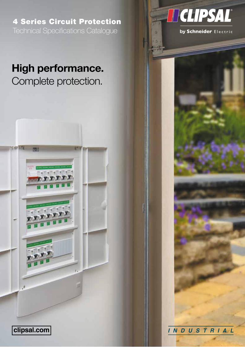
4 Series Circuit ProtectionTechnical Specifications Catalogue
High performance. Complete protection.

Clipsal 4 Series Technical Specifications Catalogue2
Clipsal 4 Series – Complete Circuit Breaker Solutions
The Clipsal 4 Series range of circuit protection comes with everything you need for your residential, commercial or industrial switchboard requirements. Included are MCBs, RCDs, MCB/RCD combinations, isolating switches, change over switches and busbar systems.
A huge variety of accessories are also available to complement the range, including auxiliary contacts, shunt trip and voltage protection devices, push-buttons, audio and visual signalling devices, timers, relays, contactors, counters and transformers.
The Clipsal 4 Series MCBs, RCDs, MCB/RCDs and Isolators comply with the latest standards AS/NZS60898, AS/NZS61008, AS/NZS61009 and AS/NZS609473 respectively.
Housing for all devices is made of sturdy, self-extinguishing material in a new white colour to suit most switchboard designs.
Each miniature circuit breaker has ‘lift-up’ terminals with combination head screws. Additional safety is provided with ‘ON’ and ‘OFF’ marking in contrasting colours on toggle mechanisms.
All devices are for 35mm DIN rail mounting with a two position DIN clip of heavy duty moulded material. Miniature circuit breakers (MCBs) are constructed with provisions for quick, easy and safe field application of auxiliary contacts and shunt trip release mechanisms. Mechanism locking and sealing wire facilities are also provided where required.
First established in 1920, Clipsal is Australia’s number one manufacturer of electrical products, accessories and solutions. Over the years Clipsal have grown and evolved with great success, and continued to manufacture product at multiple facilities across Australia. As an industry leader, Clipsal is dedicated to supplying customers with the most innovative and sustainable electrical solutions available on the market. Clipsal, as part of Schneider Electric, the largest global specialists in energy management, enables us to provide a total electrical solution for any project or application.
About 4 SeriesOverview
3
ContentsPage 4 Mini Circuit Breakers - MCB
Page 18 Residual Current Devices - Safety Switch - RCCB
Page 42 Main Switches
Page 48 Accessories
Page 72 Technical Information
Page 100 Index
Miniature Circuit Breakers
Clipsal 4 Series Technical Specifications Catalogue4
4 Series
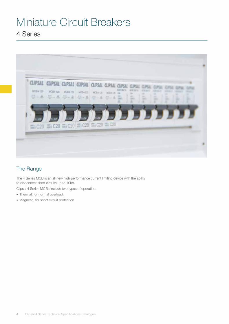
The Range
The 4 Series MCB is an all new high performance current limiting device with the ability to disconnect short circuits up to 10kA.
Clipsal 4 Series MCBs include two types of operation:
• Thermal, for normal overload.
• Magnetic, for short circuit protection.
Miniature Circuit Breakers4 Series
5
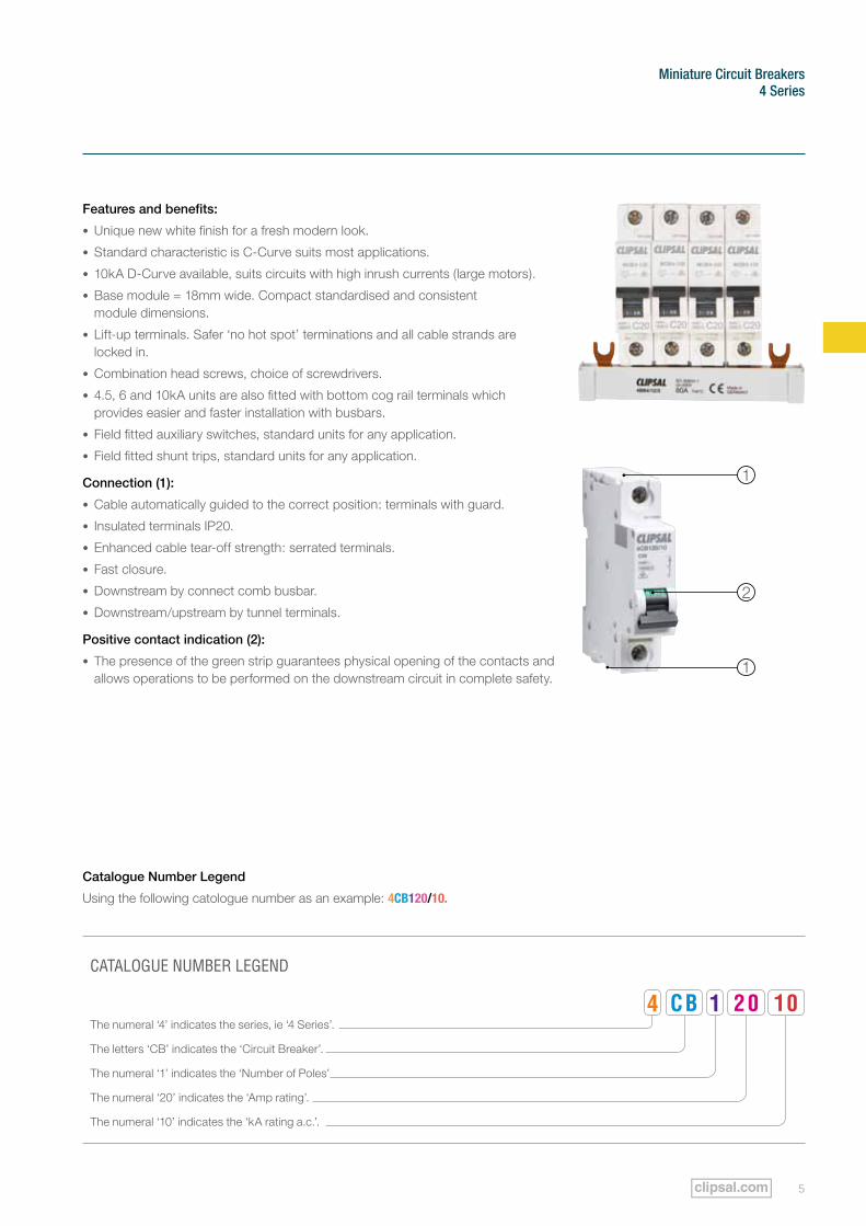
Features and benefits:
• Unique new white finish for a fresh modern look.
• Standard characteristic is C-Curve suits most applications.
• 10kA D-Curve available, suits circuits with high inrush currents (large motors).
• Base module = 18mm wide. Compact standardised and consistent module dimensions.
• Lift-up terminals. Safer ‘no hot spot’ terminations and all cable strands are locked in.
• Combination head screws, choice of screwdrivers.
• 4.5, 6 and 10kA units are also fitted with bottom cog rail terminals which provides easier and faster installation with busbars.
• Field fitted auxiliary switches, standard units for any application.
• Field fitted shunt trips, standard units for any application.
Connection (1):
• Cable automatically guided to the correct position: terminals with guard.
• Insulated terminals IP20.
• Enhanced cable tear-off strength: serrated terminals.
• Fast closure.
• Downstream by connect comb busbar.
• Downstream/upstream by tunnel terminals.
Positive contact indication (2):
• The presence of the green strip guarantees physical opening of the contacts and allows operations to be performed on the downstream circuit in complete safety.
Catalogue Number Legend
Using the following catologue number as an example: 4CB120/10.
CATALOGUE NUMBER LEGEND
The numeral ‘4’ indicates the series, ie ‘4 Series’.
The letters ‘CB’ indicates the ‘Circuit Breaker’.
The numeral ‘1’ indicates the ‘Number of Poles’
The numeral ‘20’ indicates the ‘Amp rating’.
The numeral ‘10’ indicates the ‘kA rating a.c.’.
4 CB 1 20 10
2
1
1
Miniature Circuit Breakers
Clipsal 4 Series Technical Specifications Catalogue6
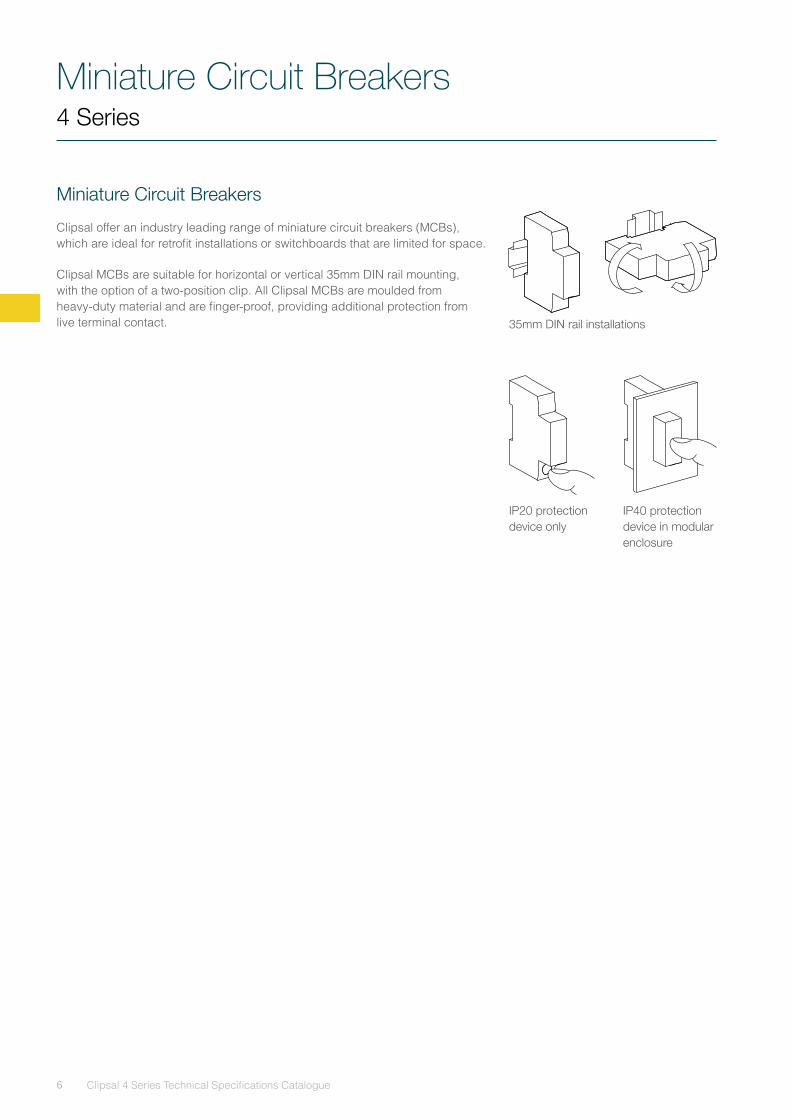
Miniature Circuit Breakers
Clipsal offer an industry leading range of miniature circuit breakers (MCBs), which are ideal for retrofit installations or switchboards that are limited for space.
Clipsal MCBs are suitable for horizontal or vertical 35mm DIN rail mounting, with the option of a two-position clip. All Clipsal MCBs are moulded from heavy-duty material and are finger-proof, providing additional protection from live terminal contact. 35mm DIN rail installations
IP20 protection device only
IP40 protection device in modular enclosure
4 Series
Miniature Circuit Breakers4 Series
7
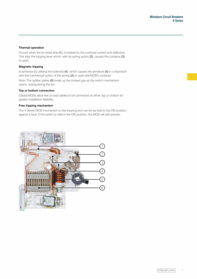
Thermal operation
Occurs when the bi-metal strip (1), is heated by the overload current and deflected. This trips the tripping lever which, with its spring action (2), causes the contacts (3) to open.
Magnetic tripping
Is achieved by utilising the solenoid (4), which causes the armature (5) in conjunction with the mechanical action of the spring (2) to open the MCB’s contacts.
Note: The splitter plates (6) break up the ionised gas as the switch mechanism opens, extinguishing the arc.
Top or bottom connection
Clipsal MCBs allow line or load cables to be connected at either top or bottom for greater installation flexibility.
Free tripping mechanism
The 4 Series MCB mechanism is free tripping and cannot be held in the ON position against a fault. If the switch is held in the ON position, the MCB will still operate.
5
6
4
3
2
1
Miniature Circuit Breakers
Clipsal 4 Series Technical Specifications Catalogue8
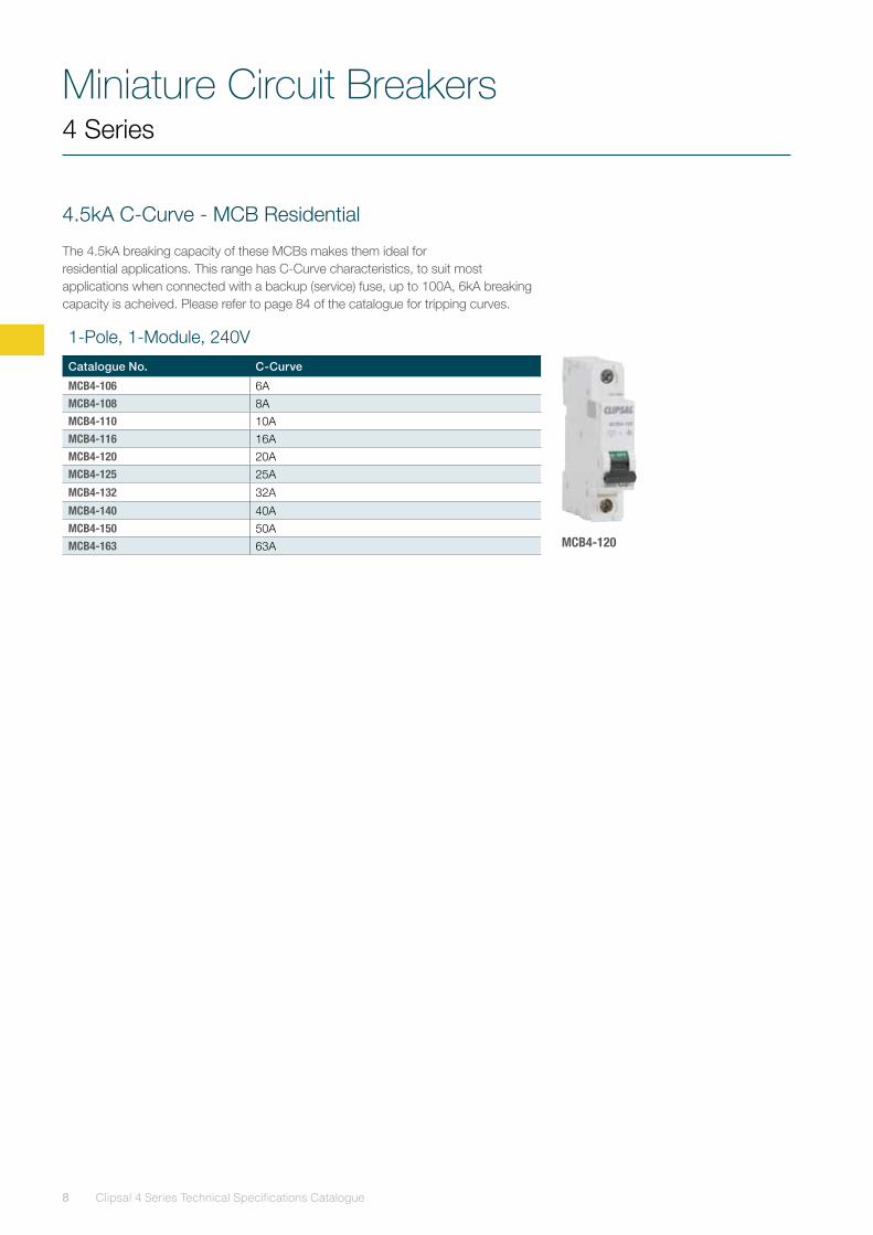
4.5kA C-Curve - MCB Residential
The 4.5kA breaking capacity of these MCBs makes them ideal for residential applications. This range has C-Curve characteristics, to suit most applications when connected with a backup (service) fuse, up to 100A, 6kA breaking capacity is acheived. Please refer to page 84 of the catalogue for tripping curves.
4 Series
1-Pole, 1-Module, 240V
Catalogue No. C-Curve
MCB4-106 6AMCB4-108 8AMCB4-110 10AMCB4-116 16AMCB4-120 20AMCB4-125 25A
MCB4-132 32A
MCB4-140 40AMCB4-150 50AMCB4-163 63A MCB4-120
Miniature Circuit Breakers4 Series
9
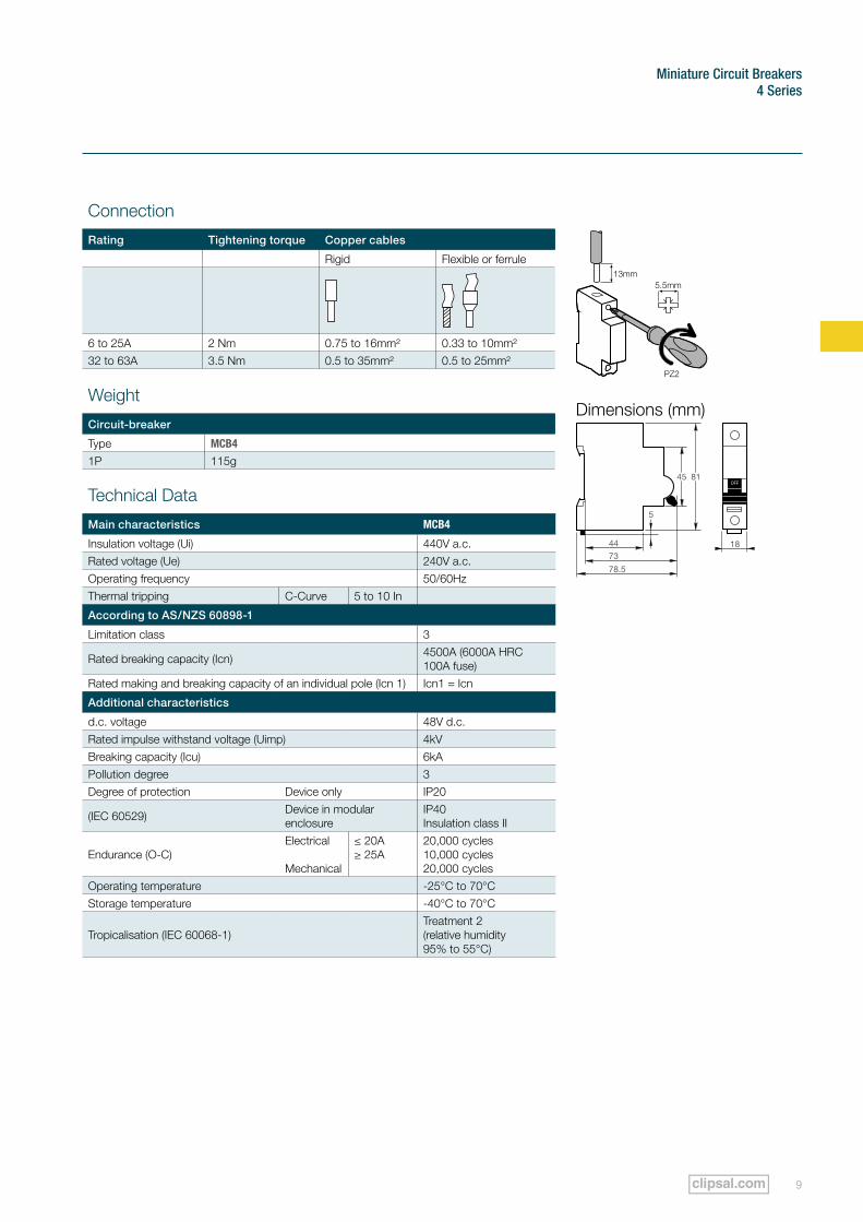
Connection
Rating Tightening torque Copper cables
Rigid Flexible or ferrule
6 to 25A 2 Nm 0.75 to 16mm² 0.33 to 10mm²32 to 63A 3.5 Nm 0.5 to 35mm² 0.5 to 25mm²
Weight
Circuit-breaker
Type MCB4
1P 115g
Technical Data
Main characteristics MCB4
Insulation voltage (Ui) 440V a.c.Rated voltage (Ue) 240V a.c.Operating frequency 50/60HzThermal tripping C-Curve 5 to 10 In
According to AS/NZS 60898-1
Limitation class 3
Rated breaking capacity (Icn) 4500A (6000A HRC 100A fuse)
Rated making and breaking capacity of an individual pole (Icn 1) Icn1 = Icn
Additional characteristics
d.c. voltage 48V d.c.Rated impulse withstand voltage (Uimp) 4kVBreaking capacity (Icu) 6kAPollution degree 3Degree of protection Device only IP20
(IEC 60529) Device in modular enclosure
IP40 Insulation class II
Endurance (O-C)Electrical Mechanical
≤ 20A ≥ 25A
20,000 cycles10,000 cycles20,000 cycles
Operating temperature -25°C to 70°CStorage temperature -40°C to 70°C
Tropicalisation (IEC 60068-1)Treatment 2 (relative humidity 95% to 55°C)
45 81
5
44
73
78.5
OFF
18
Dimensions (mm)
Miniature Circuit Breakers
Clipsal 4 Series Technical Specifications Catalogue10
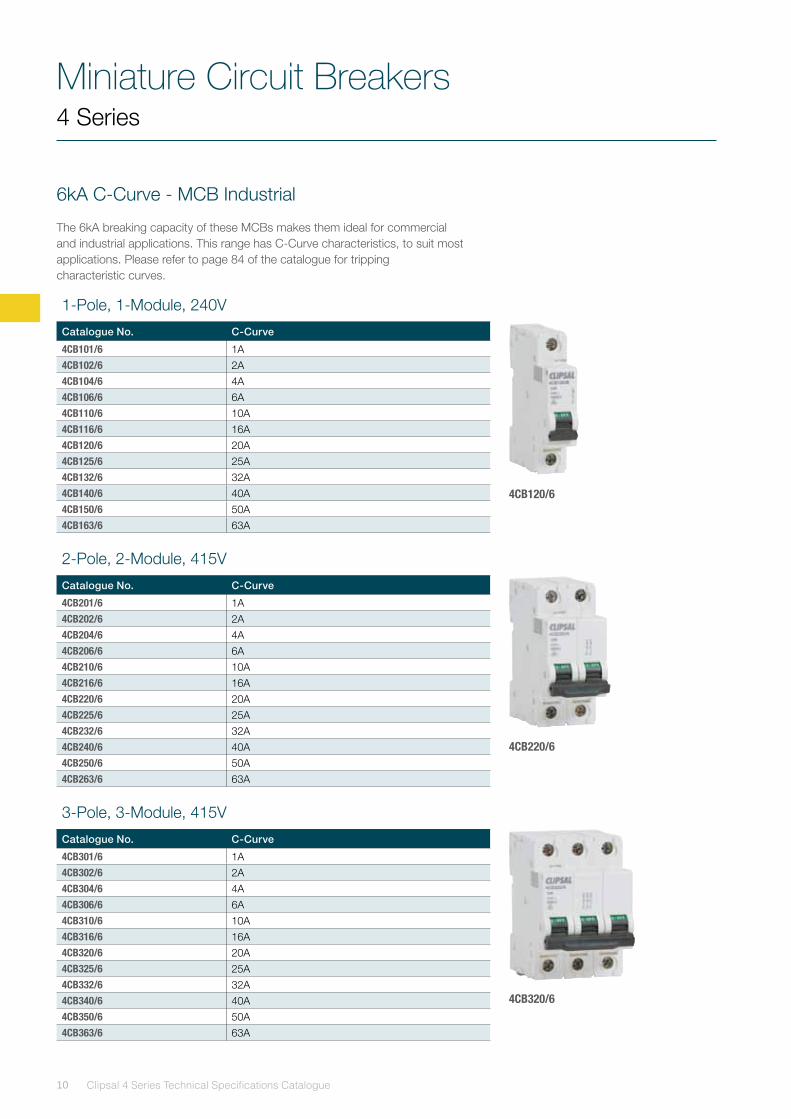
4CB120/6
4CB220/6
4CB320/6
6kA C-Curve - MCB Industrial
The 6kA breaking capacity of these MCBs makes them ideal for commercial and industrial applications. This range has C-Curve characteristics, to suit most applications. Please refer to page 84 of the catalogue for tripping characteristic curves.
1-Pole, 1-Module, 240V
Catalogue No. C-Curve
4CB101/6 1A4CB102/6 2A4CB104/6 4A4CB106/6 6A4CB110/6 10A4CB116/6 16A4CB120/6 20A4CB125/6 25A4CB132/6 32A4CB140/6 40A4CB150/6 50A4CB163/6 63A
2-Pole, 2-Module, 415V
Catalogue No. C-Curve
4CB201/6 1A4CB202/6 2A4CB204/6 4A4CB206/6 6A4CB210/6 10A4CB216/6 16A4CB220/6 20A4CB225/6 25A4CB232/6 32A4CB240/6 40A4CB250/6 50A4CB263/6 63A
3-Pole, 3-Module, 415V
Catalogue No. C-Curve
4CB301/6 1A4CB302/6 2A4CB304/6 4A4CB306/6 6A4CB310/6 10A4CB316/6 16A4CB320/6 20A4CB325/6 25A4CB332/6 32A4CB340/6 40A4CB350/6 50A4CB363/6 63A
4 Series
Miniature Circuit Breakers4 Series
11
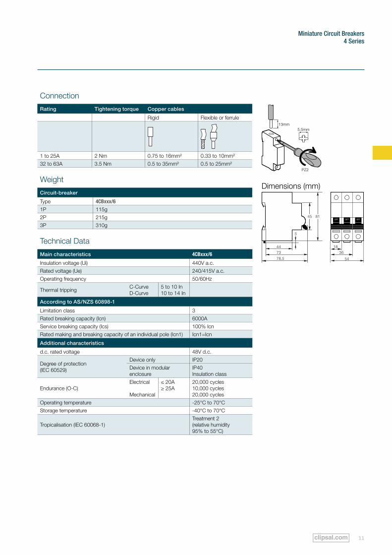
Connection
Rating Tightening torque Copper cables
Rigid Flexible or ferrule
1 to 25A 2 Nm 0.75 to 16mm² 0.33 to 10mm²32 to 63A 3.5 Nm 0.5 to 35mm² 0.5 to 25mm²
Weight
Circuit-breaker
Type 4CBxxx/6
1P 115g2P 215g3P 310g
Technical Data
Main characteristics 4CBxxx/6
Insulation voltage (Ui) 440V a.c.Rated voltage (Ue) 240/415V a.c.Operating frequency 50/60Hz
Thermal tripping C-Curve D-Curve
5 to 10 In 10 to 14 In
According to AS/NZS 60898-1
Limitation class 3Rated breaking capacity (Icn) 6000AService breaking capacity (Ics) 100% IcnRated making and breaking capacity of an individual pole (Icn1) Icn1=Icn
Additional characteristics
d.c. rated voltage 48V d.c.
Degree of protection(IEC 60529)
Device only IP20Device in modular enclosure
IP40 Insulation class
Endurance (O-C)Electrical Mechanical
≤ 20A ≥ 25A
20,000 cycles10,000 cycles20,000 cycles
Operating temperature -25°C to 70°CStorage temperature -40°C to 70°C
Tropicalisation (IEC 60068-1)Treatment 2 (relative humidity 95% to 55°C)
OFFOFF OFF45 81
5
44 1836
54
73
78.5
Dimensions (mm)
Miniature Circuit Breakers
Clipsal 4 Series Technical Specifications Catalogue12
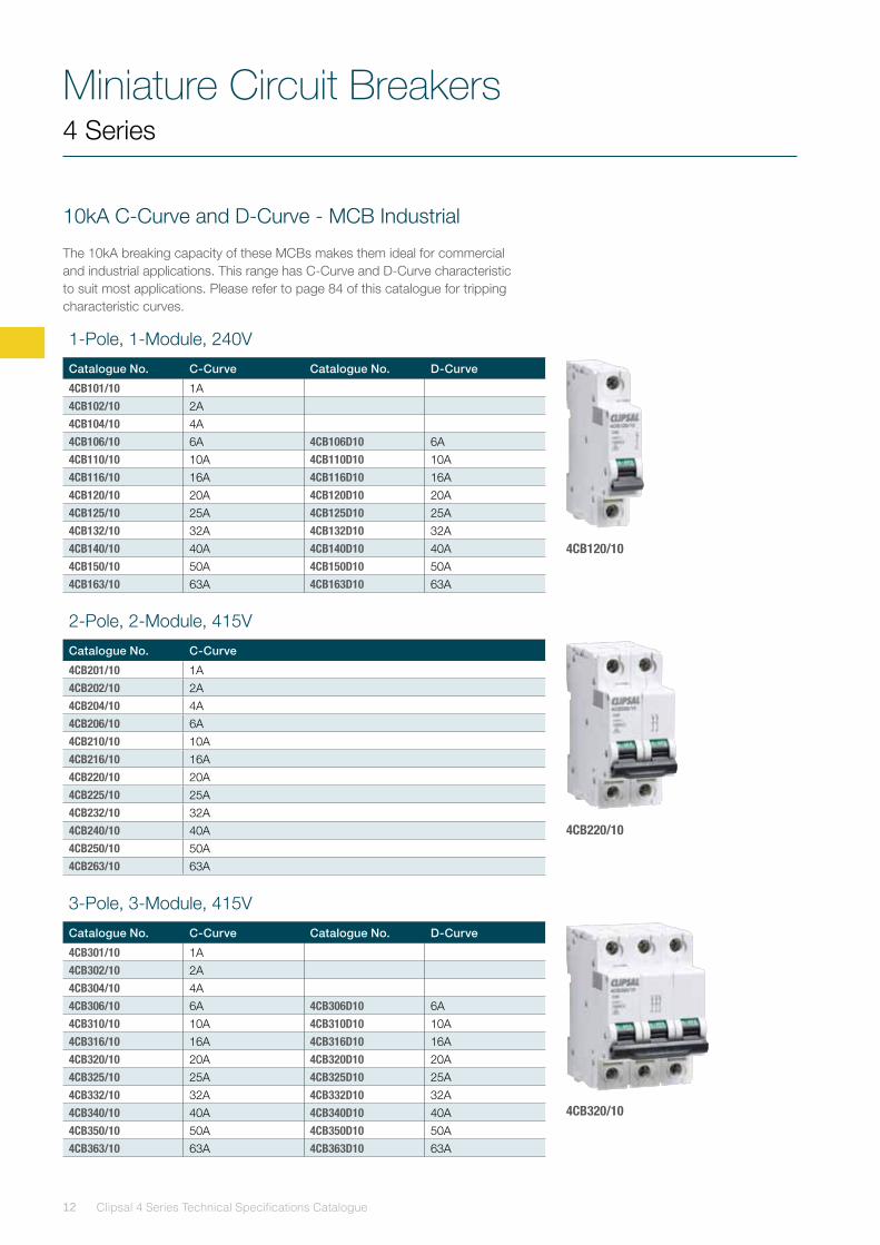
4CB120/10
4CB220/10
4CB320/10
10kA C-Curve and D-Curve - MCB Industrial
The 10kA breaking capacity of these MCBs makes them ideal for commercial and industrial applications. This range has C-Curve and D-Curve characteristic to suit most applications. Please refer to page 84 of this catalogue for tripping characteristic curves.
1-Pole, 1-Module, 240V
Catalogue No. C-Curve Catalogue No. D-Curve
4CB101/10 1A4CB102/10 2A4CB104/10 4A4CB106/10 6A 4CB106D10 6A4CB110/10 10A 4CB110D10 10A4CB116/10 16A 4CB116D10 16A4CB120/10 20A 4CB120D10 20A4CB125/10 25A 4CB125D10 25A4CB132/10 32A 4CB132D10 32A4CB140/10 40A 4CB140D10 40A4CB150/10 50A 4CB150D10 50A4CB163/10 63A 4CB163D10 63A
3-Pole, 3-Module, 415V
Catalogue No. C-Curve Catalogue No. D-Curve
4CB301/10 1A4CB302/10 2A4CB304/10 4A4CB306/10 6A 4CB306D10 6A4CB310/10 10A 4CB310D10 10A4CB316/10 16A 4CB316D10 16A4CB320/10 20A 4CB320D10 20A4CB325/10 25A 4CB325D10 25A4CB332/10 32A 4CB332D10 32A4CB340/10 40A 4CB340D10 40A4CB350/10 50A 4CB350D10 50A4CB363/10 63A 4CB363D10 63A
2-Pole, 2-Module, 415V
Catalogue No. C-Curve
4CB201/10 1A4CB202/10 2A4CB204/10 4A4CB206/10 6A4CB210/10 10A4CB216/10 16A4CB220/10 20A4CB225/10 25A4CB232/10 32A4CB240/10 40A4CB250/10 50A4CB263/10 63A
4 Series
Miniature Circuit Breakers4 Series
13
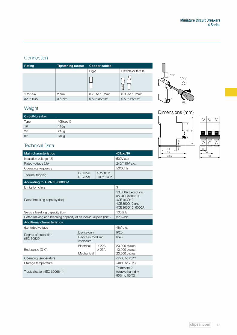
Connection
Rating Tightening torque Copper cables
Rigid Flexible or ferrule
1 to 25A 2 Nm 0.75 to 16mm² 0.33 to 10mm²32 to 63A 3.5 Nm 0.5 to 35mm² 0.5 to 25mm²
Weight
Circuit-breaker
Type 4CBxxx/10
1P 115g2P 215g3P 310g
Technical Data
Main characteristics 4CBxxx/10
Insulation voltage (Ui) 500V a.c.Rated voltage (Ue) 240/415V a.c.Operating frequency 50/60Hz
Thermal tripping C-Curve D-Curve
5 to 10 In 10 to 14 In
According to AS/NZS 60898-1
Limitation class 3
Rated breaking capacity (Icn)
10,000A Except cat. no. 4CB150D10, 4CB163D10, 4CB350D10 and 4CB363D10: 6000A
Service breaking capacity (Ics) 100% IcnRated making and breaking capacity of an individual pole (Icn1) Icn1=Icn
Additional characteristics
d.c. rated voltage 48V d.c.
Degree of protection(IEC 60529)
Device only IP20Device in modular enclosure
IP40
Endurance (O-C)Electrical Mechanical
≤ 20A ≥ 25A
20,000 cycles10,000 cycles20,000 cycles
Operating temperature -25°C to 70°CStorage temperature -40°C to 70°C
Tropicalisation (IEC 60068-1)Treatment 2 (relative humidity 95% to 55°C)
45 81
5
44
OFFOFF OFF
1836
54
73
78.5
Dimensions (mm)
Miniature Circuit Breakers
Clipsal 4 Series Technical Specifications Catalogue14
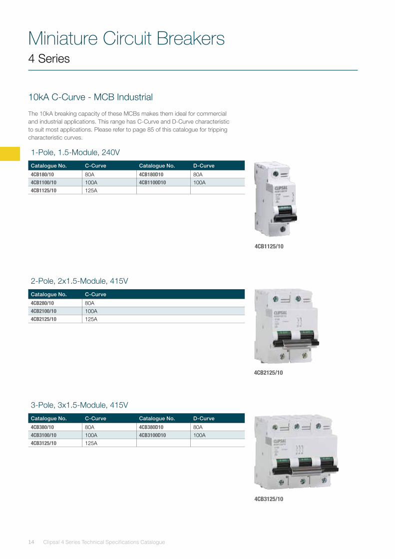
10kA C-Curve - MCB Industrial
The 10kA breaking capacity of these MCBs makes them ideal for commercial and industrial applications. This range has C-Curve and D-Curve characteristic to suit most applications. Please refer to page 85 of this catalogue for tripping characteristic curves.
4 Series
4CB1125/10
4CB2125/10
4CB3125/10
1-Pole, 1.5-Module, 240V
Catalogue No. C-Curve Catalogue No. D-Curve
4CB180/10 80A 4CB180D10 80A4CB1100/10 100A 4CB1100D10 100A4CB1125/10 125A
3-Pole, 3x1.5-Module, 415V
Catalogue No. C-Curve Catalogue No. D-Curve
4CB380/10 80A 4CB380D10 80A4CB3100/10 100A 4CB3100D10 100A4CB3125/10 125A
2-Pole, 2x1.5-Module, 415V
Catalogue No. C-Curve
4CB280/10 80A4CB2100/10 100A4CB2125/10 125A
Miniature Circuit Breakers4 Series
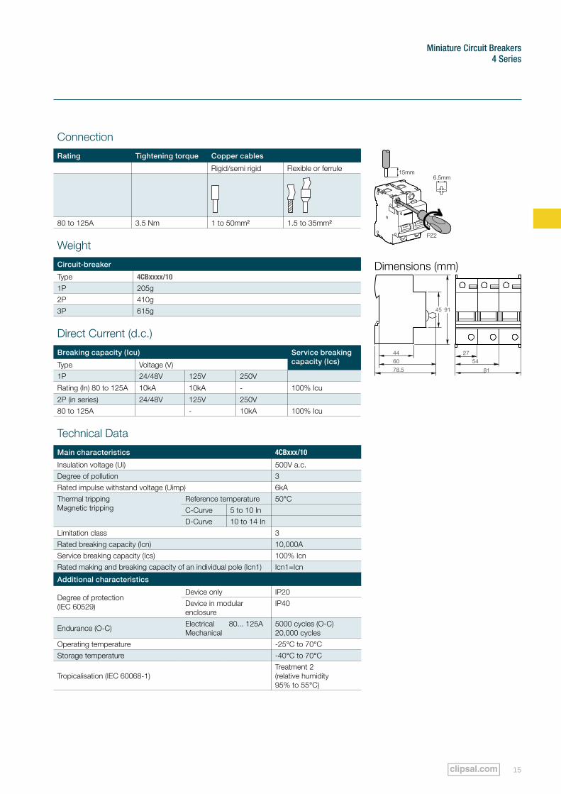
15
Connection
Rating Tightening torque Copper cables
Rigid/semi rigid Flexible or ferrule
80 to 125A 3.5 Nm 1 to 50mm² 1.5 to 35mm²
Weight
Circuit-breaker
Type 4CBxxxx/10
1P 205g2P 410g3P 615g
Direct Current (d.c.)
Breaking capacity (Icu) Service breaking capacity (Ics)Type Voltage (V)
1P 24/48V 125V 250V
Rating (In) 80 to 125A 10kA 10kA - 100% Icu
2P (in series) 24/48V 125V 250V80 to 125A - 10kA 100% Icu
Technical Data
Main characteristics 4CBxxx/10
Insulation voltage (Ui) 500V a.c.Degree of pollution 3Rated impulse withstand voltage (Uimp) 6kAThermal trippingMagnetic tripping
Reference temperature 50°CC-Curve 5 to 10 InD-Curve 10 to 14 In
Limitation class 3Rated breaking capacity (Icn) 10,000AService breaking capacity (Ics) 100% IcnRated making and breaking capacity of an individual pole (Icn1) Icn1=Icn
Additional characteristics
Degree of protection(IEC 60529)
Device only IP20Device in modular enclosure
IP40
Endurance (O-C) Electrical 80... 125A Mechanical
5000 cycles (O-C)20,000 cycles
Operating temperature -25°C to 70°CStorage temperature -40°C to 70°C
Tropicalisation (IEC 60068-1)Treatment 2 (relative humidity 95% to 55°C)
Dimensions (mm)
45 91
44 2754
81
60
78.5
Miniature Circuit Breakers
Clipsal 4 Series Technical Specifications Catalogue16
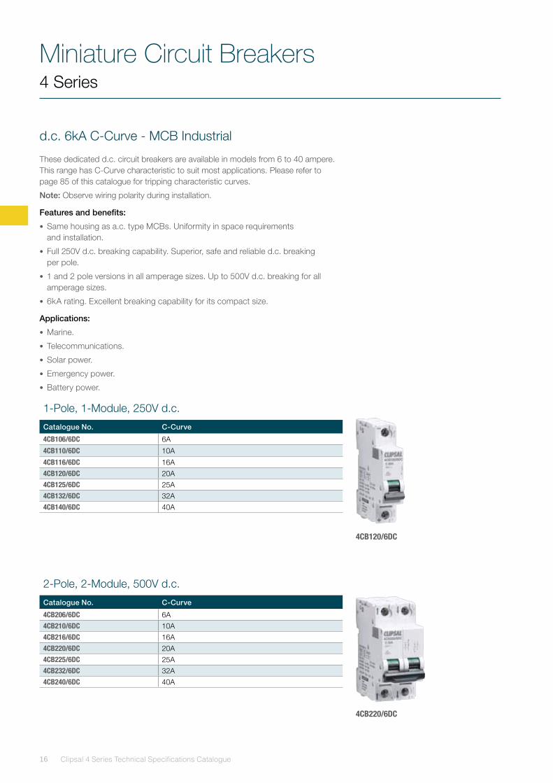
d.c. 6kA C-Curve - MCB Industrial
These dedicated d.c. circuit breakers are available in models from 6 to 40 ampere.This range has C-Curve characteristic to suit most applications. Please refer to page 85 of this catalogue for tripping characteristic curves.
Note: Observe wiring polarity during installation.
Features and benefits:
• Same housing as a.c. type MCBs. Uniformity in space requirements and installation.
• Full 250V d.c. breaking capability. Superior, safe and reliable d.c. breaking per pole.
• 1 and 2 pole versions in all amperage sizes. Up to 500V d.c. breaking for all amperage sizes.
• 6kA rating. Excellent breaking capability for its compact size.
Applications:
• Marine.
• Telecommunications.
• Solar power.
• Emergency power.
• Battery power.
4 Series
4CB120/6DC
4CB220/6DC
1-Pole, 1-Module, 250V d.c.
Catalogue No. C-Curve
4CB106/6DC 6A
4CB110/6DC 10A
4CB116/6DC 16A4CB120/6DC 20A4CB125/6DC 25A4CB132/6DC 32A4CB140/6DC 40A
2-Pole, 2-Module, 500V d.c.
Catalogue No. C-Curve
4CB206/6DC 6A4CB210/6DC 10A4CB216/6DC 16A4CB220/6DC 20A4CB225/6DC 25A4CB232/6DC 32A4CB240/6DC 40A
Miniature Circuit Breakers4 Series
17
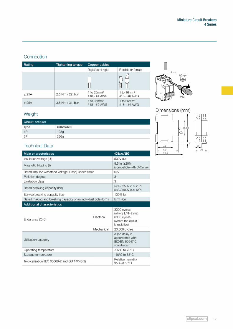
Connection
Rating Tightening torque Copper cables
Rigid/semi rigid Flexible or ferrule
≤ 25A 2.5 Nm / 22 Ib.in 1 to 25mm² #18 - #4 AWG
1 to 16mm² #18 - #6 AWG
> 25A 3.5 Nm / 31 Ib.in 1 to 35mm² #18 - #2 AWG
1 to 25mm² #18 - #4 AWG
Weight
Circuit-breaker
Type 4CBxxx/6DC
1P 128g2P 256g
O-OFF
O-OFF
Technical Data
Main characteristics 4CBxxx/6DC
Insulation voltage (Ui) 500V d.c.
Magnetic tripping (li) 8.5 In (±20%) (compatible with C-Curve)
Rated impulse withstand voltage (Uimp) under frame 6kVPollution degree 3Limitation class 3
Rated breaking capacity (Icn) 5kA / 250V d.c. (1P) 5kA / 500V d.c. (2P)
Service breaking capacity (Ics) 100% IcnRated making and breaking capacity of an individual pole (Icn1) Icn1=Icn
Additional characteristics
Endurance (O-C)Electrical
3000 cycles (where L/R=2 ms) 6000 cycles (where the circuit is resistive)
Mechanical 20,000 cycles
Utilisation category
A (no delay in accordance with IEC/EN 60947-2 standards)
Operating temperature -25°C to 70°CStorage temperature -40°C to 85°C
Tropicalisation (IEC 60068-2 and GB 14048.2) Relative humidity 95% at 55°C
Dimensions (mm)
1836
81
5
78.5
44
60
45
Residual Current Devices
Clipsal 4 Series Technical Specifications Catalogue18
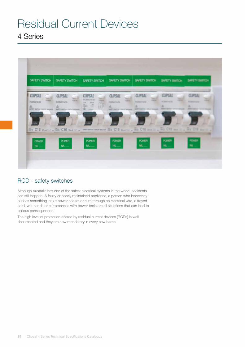
RCD - safety switches
Although Australia has one of the safest electrical systems in the world, accidents can still happen. A faulty or poorly maintained appliance, a person who innocently pushes something into a power socket or cuts through an electrical wire, a frayed cord, wet hands or carelessness with power tools are all situations that can lead to serious consequences.
The high level of protection offered by residual current devices (RCDs) is well documented and they are now mandatory in every new home.
4 Series
Residual Current Devices 4 Series
19
How an RCD works
The RCD works by constantly monitoring and comparing the current flow in both the Active and Neutral circuits of an electrical installation.
During normal operation, these Active and Neutral currents are in balance. However, should any current flow to Earth, an imbalance is created in these circuits. If this imbalance is sufficient, the RCD will cut the electrical supply.
Apart from the protection to people that an RCD offers, it will also cut off power to expensive electrical equipment in the event of an electrical fault to Earth. This protects appliances against costly damage and the installation against fire, resulting from faults of this nature.
Checking installations and appliances before installation
It is important to check the installation thoroughly to ensure that there is no inherent leakage or other problems in the installation, which will cause commissioning problems or other tripping.
Any leakage greater than 5mA will need to be located and eliminated.
Residual Current Devices
Clipsal 4 Series Technical Specifications Catalogue20
Switchboard Mounted RCDs - Safety Switches
These RCDs incorporate the same housing and installation features as the MCBs. With a range that includes pulse current sensitive and super immune devices, there’s a unit for every application.
Features and benefits:
• Same housing and installation features as the MCBs. Safe, easy and fast installation.
• Standard large coloured test button. Simple and convenient testing.
• Leading and lagging Neutral devices. Protects downstream sensitive ‘no-floating’ star-point.
• Large range of delayed surge-proof and pulse current sensitive devices. Availability of a unit for any application.
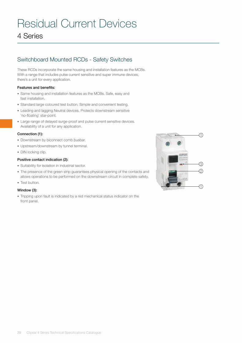
Connection (1):
• Downstream by biconnect comb busbar.
• Upstream/downstream by tunnel terminal.
• DIN locking clip.
Positive contact indication (2):
• Suitability for isolation in industrial sector.
• The presence of the green strip guarantees physical opening of the contacts and allows operations to be performed on the downstream circuit in complete safety.
• Test button.
Window (3):
• Tripping upon fault is indicated by a red mechanical status indicator on the front panel.
1
1
2
3
4 Series
Residual Current Devices 4 Series
21
Design improvements
Clipsal’s on-going research has resulted in significant design improvements, which have eliminated or reduced the incidence of nuisance tripping.
Tertiary winding is now fitted to all electromechanical 30mA Clipsal RCDs to prevent tripping caused by high frequency residual currents.
In addition to our standard RCD, three special RCDs have been designed: the SI-type, S-type and SIS-type.
Clipsal S-Type (selective), SI-Type (super immune) and SIS-Type (super immune and selective) RCDs
Selective type uses a simple network on the secondary winding to charge a capacitor to a certain level before discharging it into the tripping relay.
These devices provide a high level of immunity to tripping caused by short term transients and capacitive surges, which can occur when long cable runs are present that inherently have a high capacitance to Earth.
The SI range of RCDs provides reliable disturbance free tripping, mostly caused by non-dangerous Earth leakage.
The SIS range of RCDs provides a combination of selective and super immune features. SIS-type RCDs are highly recommended for installations where variations on voltage oscillations exist, either by high, or slow and damped, frequency.
Applications
S-Type
• Machinery.
• Series installation with other RCDs.
• Cable systems.
SI-Type
• High dependency installations.
• Computers.
• Fluorescent lighting with electronic ballasts.
SIS-Type
• Servers.
• Lighting strike zones.
• Application with drastic variation in voltage oscillations.
Selective S-Type
• Machinery.
• Series installation with other.
• RCD types.
• Cable systems.
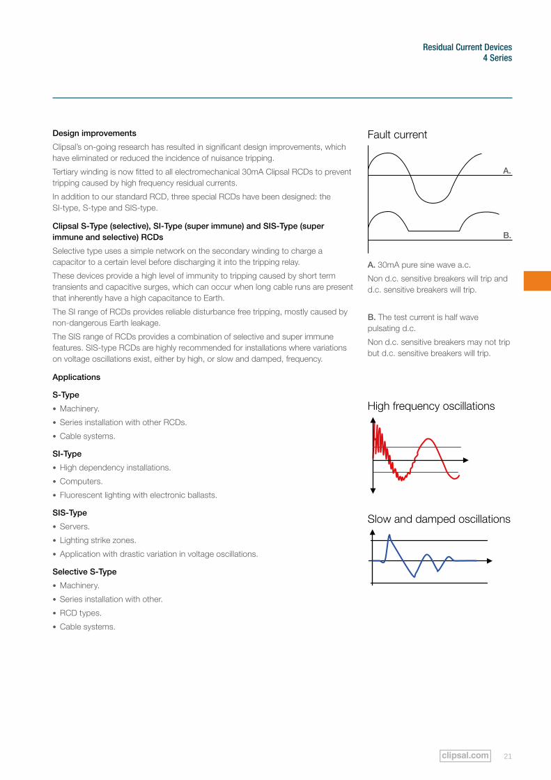
Fault current
A.
B.
Slow and damped oscillations
A. 30mA pure sine wave a.c.
Non d.c. sensitive breakers will trip and d.c. sensitive breakers will trip.
B. The test current is half wave pulsating d.c.
Non d.c. sensitive breakers may not trip but d.c. sensitive breakers will trip.
High frequency oscillations
Residual Current Devices
Clipsal 4 Series Technical Specifications Catalogue22
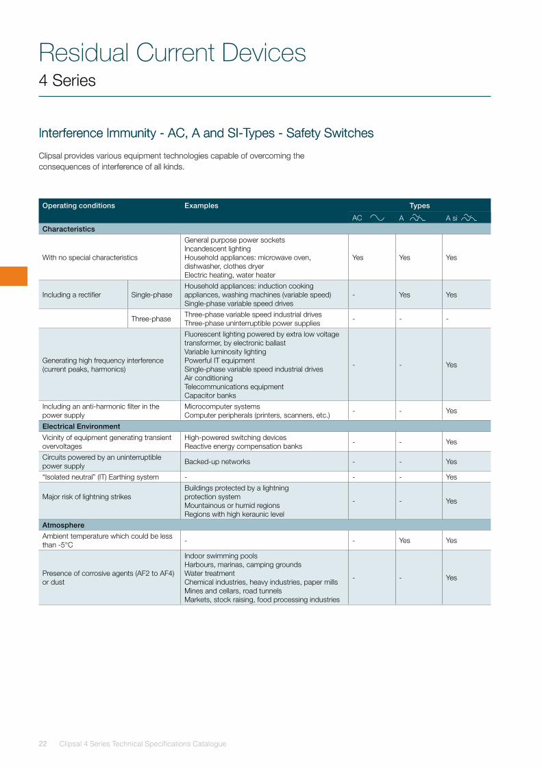
Interference Immunity - AC, A and SI-Types - Safety Switches
Clipsal provides various equipment technologies capable of overcoming the consequences of interference of all kinds.
Interference Immunity - AC, A and SI-Types - Safety Switches
Clipsal provides various equipment technologies capable of overcoming the consequences of interference of all kinds.
Operating conditions Examples Types
AC A A si Characteristics
With no special characteristics
General purpose power socketsIncandescent lightingHousehold appliances: microwave oven, dishwasher, clothes dryerElectric heating, water heater
Yes Yes Yes
Including a rectifier Single-phaseHousehold appliances: induction cooking appliances, washing machines (variable speed)Single-phase variable speed drives
- Yes Yes
Three-phase Three-phase variable speed industrial drivesThree-phase uninterruptible power supplies - - -
Generating high frequency interference (current peaks, harmonics)
Fluorescent lighting powered by extra low voltage transformer, by electronic ballastVariable luminosity lightingPowerful IT equipmentSingle-phase variable speed industrial drivesAir conditioningTelecommunications equipmentCapacitor banks
- - Yes
Including an anti-harmonic filter in the power supply
Microcomputer systemsComputer peripherals (printers, scanners, etc.) - - Yes
Electrical Environment
Vicinity of equipment generating transient overvoltages
High-powered switching devicesReactive energy compensation banks - - Yes
Circuits powered by an uninterruptible power supply Backed-up networks - - Yes
“Isolated neutral” (IT) Earthing system - - - Yes
Major risk of lightning strikesBuildings protected by a lightning protection systemMountainous or humid regionsRegions with high keraunic level
- - Yes
AtmosphereAmbient temperature which could be less than -5°C - - Yes Yes
Presence of corrosive agents (AF2 to AF4) or dust
Indoor swimming poolsHarbours, marinas, camping groundsWater treatmentChemical industries, heavy industries, paper millsMines and cellars, road tunnelsMarkets, stock raising, food processing industries
- - Yes
4 Series
Residual Current Devices 4 Series
23
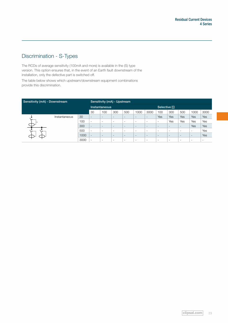
Discrimination - S-Types
The RCDs of average sensitivity (100mA and more) is available in the (S) type version. This option ensures that, in the event of an Earth fault downstream of the installation, only the defective part is switched off.
The table below shows which upstream/downstream equipment combinations provide this discrimination.
Sensitivity (mA) - Downstream Sensitivity (mA) - Upstream
Instantaneous Selective
30 100 300 500 1000 3000 100 300 500 1000 3000Instantaneous 30 - - - - - - Yes Yes Yes Yes Yes
100 - - - - - - - Yes Yes Yes Yes300 - - - - - - - - - Yes Yes500 - - - - - - - - - - Yes1000 - - - - - - - - - - Yes3000 - - - - - - - - - - -
Residual Current Devices
Clipsal 4 Series Technical Specifications Catalogue24
4 Series
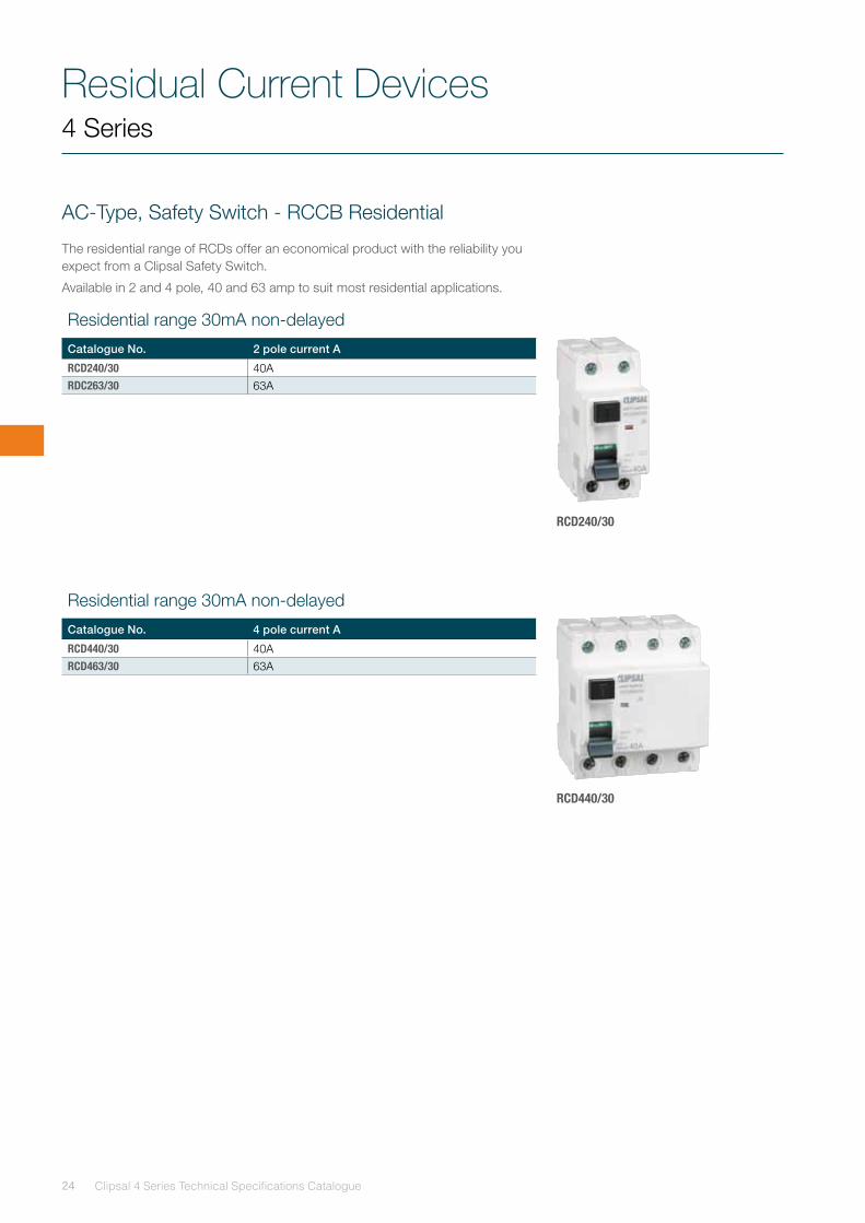
AC-Type, Safety Switch - RCCB Residential
The residential range of RCDs offer an economical product with the reliability you expect from a Clipsal Safety Switch.
Available in 2 and 4 pole, 40 and 63 amp to suit most residential applications.
RCD240/30
RCD440/30
Residential range 30mA non-delayed
Catalogue No. 2 pole current A
RCD240/30 40ARDC263/30 63A
Residential range 30mA non-delayed
Catalogue No. 4 pole current A
RCD440/30 40ARCD463/30 63A
Residual Current Devices 4 Series
25
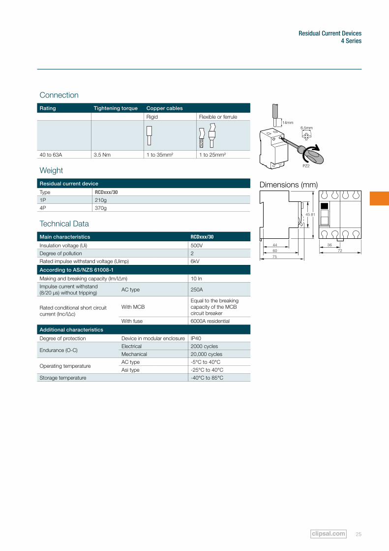
Connection
Rating Tightening torque Copper cables
Rigid Flexible or ferrule
40 to 63A 3.5 Nm 1 to 35mm² 1 to 25mm²
Weight
Residual current device
Type RCDxxx/30
1P 210g4P 370g
Technical Data
Main characteristics RCDxxx/30
Insulation voltage (Ui) 500VDegree of pollution 2Rated impulse withstand voltage (Uimp) 6kV
According to AS/NZS 61008-1
Making and breaking capacity (Im/I∆m) 10 InImpulse current withstand (8/20 µs) without tripping) AC type 250A
Rated conditional short circuit current (Inc/I∆c)
With MCBEqual to the breaking capacity of the MCB circuit breaker
With fuse 6000A residential
Additional characteristics
Degree of protection Device in modular enclosure IP40
Endurance (O-C)Electrical 2000 cyclesMechanical 20,000 cycles
Operating temperatureAC type -5°C to 40°CAsi type -25°C to 40°C
Storage temperature -40°C to 85°C
Dimensions (mm)
3672
81
75
44
60
45
Residual Current Devices
Clipsal 4 Series Technical Specifications Catalogue26
4 Series
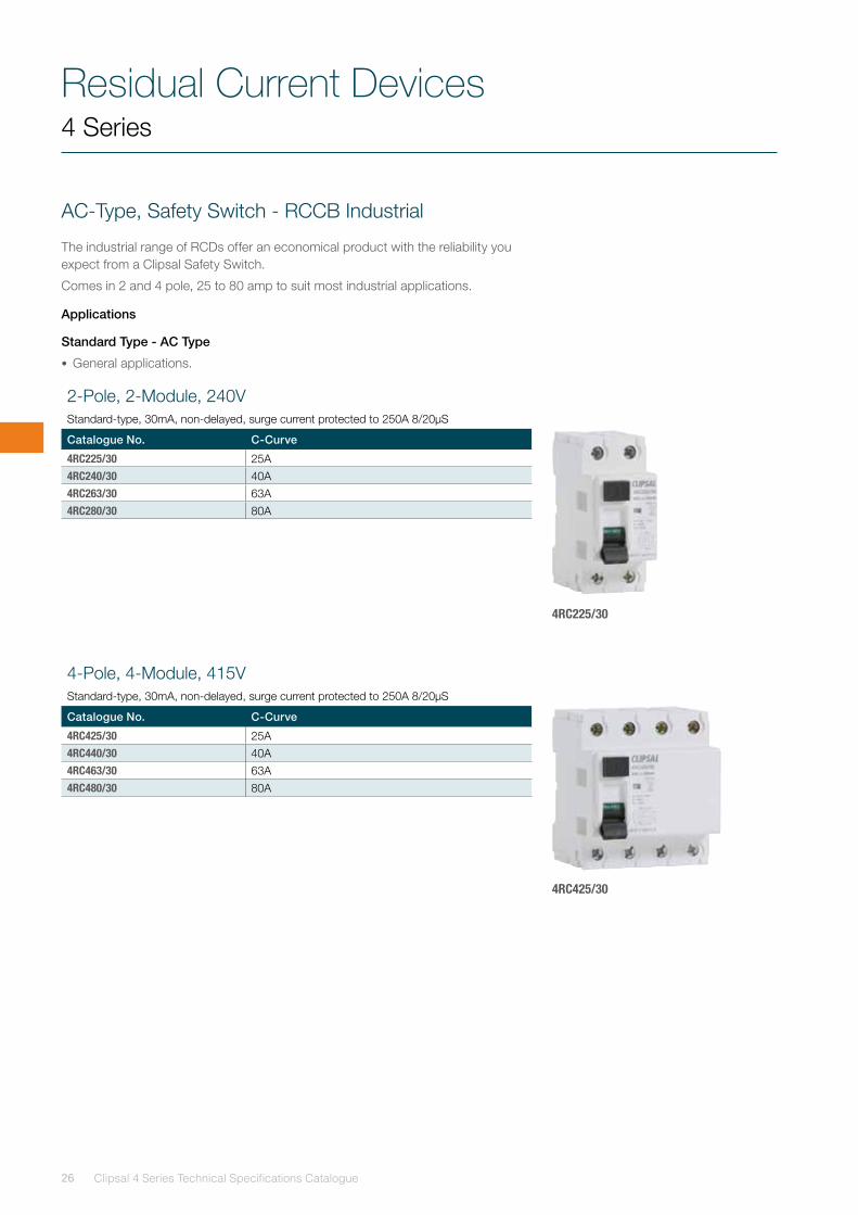
AC-Type, Safety Switch - RCCB Industrial
The industrial range of RCDs offer an economical product with the reliability you expect from a Clipsal Safety Switch.
Comes in 2 and 4 pole, 25 to 80 amp to suit most industrial applications.
Applications
Standard Type - AC Type
• General applications.
4RC225/30
4-Pole, 4-Module, 415V Standard-type, 30mA, non-delayed, surge current protected to 250A 8/20µS
Catalogue No. C-Curve
4RC425/30 25A4RC440/30 40A4RC463/30 63A4RC480/30 80A
4RC425/30
2-Pole, 2-Module, 240V Standard-type, 30mA, non-delayed, surge current protected to 250A 8/20µS
Catalogue No. C-Curve
4RC225/30 25A4RC240/30 40A4RC263/30 63A4RC280/30 80A
Residual Current Devices 4 Series
27
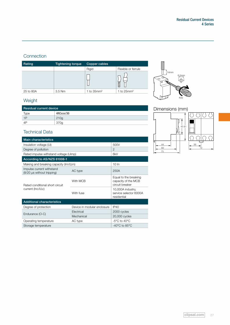
Dimensions (mm)
3672
81
75
44
60
45
Connection
Rating Tightening torque Copper cables
Rigid Flexible or ferrule
25 to 80A 3.5 Nm 1 to 35mm² 1 to 25mm²
Weight
Residual current device
Type 4RCxxx/30
1P 210g4P 370g
Technical Data
Main characteristics
Insulation voltage (Ui) 500VDegree of pollution 2Rated impulse withstand voltage (Uimp) 6kV
According to AS/NZS 61008-1
Making and breaking capacity (Im/I∆m) 10 InImpulse current withstand (8/20 µs without tripping) AC type 250A
Rated conditional short circuit current (Inc/I∆c)
With MCBEqual to the breaking capacity of the MCB circuit breaker
With fuse10,000A industry, service selector 6000A residential
Additional characteristics
Degree of protection Device in modular enclosure IP40
Endurance (O-C)Electrical 2000 cyclesMechanical 20,000 cycles
Operating temperature AC type -5°C to 40°CStorage temperature -40°C to 85°C
Residual Current Devices
Clipsal 4 Series Technical Specifications Catalogue28
4 Series
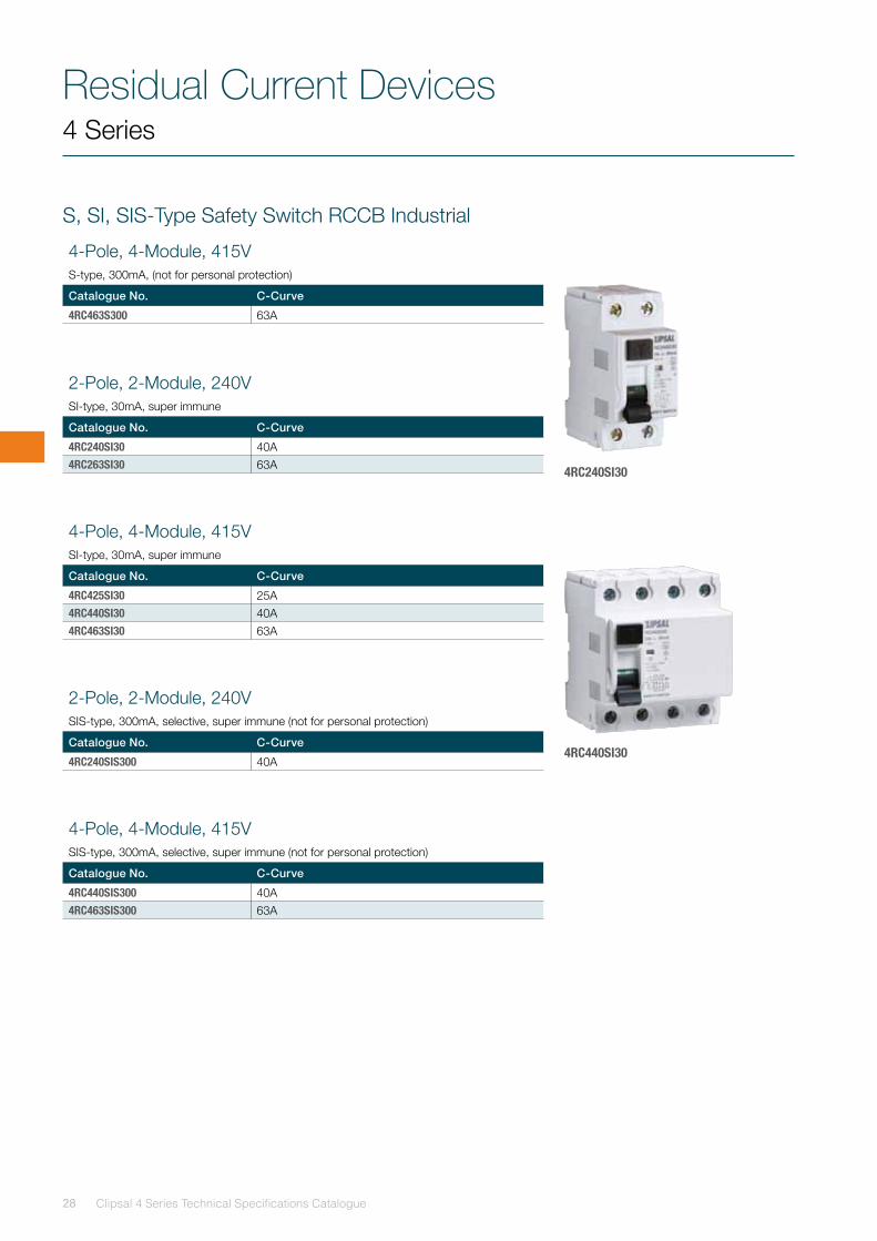
S, SI, SIS-Type Safety Switch RCCB Industrial
4RC440SI30
4RC240SI30
2-Pole, 2-Module, 240V SI-type, 30mA, super immune
Catalogue No. C-Curve
4RC240SI30 40A4RC263SI30 63A
2-Pole, 2-Module, 240V SIS-type, 300mA, selective, super immune (not for personal protection)
Catalogue No. C-Curve
4RC240SIS300 40A
4-Pole, 4-Module, 415V SI-type, 30mA, super immune
Catalogue No. C-Curve
4RC425SI30 25A4RC440SI30 40A4RC463SI30 63A
4-Pole, 4-Module, 415V SIS-type, 300mA, selective, super immune (not for personal protection)
Catalogue No. C-Curve
4RC440SIS300 40A4RC463SIS300 63A
4-Pole, 4-Module, 415V S-type, 300mA, (not for personal protection)
Catalogue No. C-Curve
4RC463S300 63A
Residual Current Devices 4 Series
29
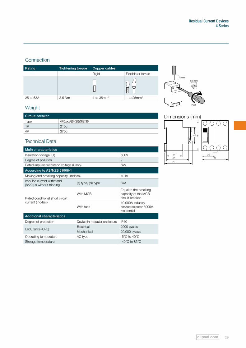
Dimensions (mm)
3672
81
75
44
60
45
Connection
Rating Tightening torque Copper cables
Rigid Flexible or ferrule
25 to 63A 3.5 Nm 1 to 35mm² 1 to 25mm²
Weight
Circuit-breaker
Type 4RCxxx/(S)(SI)(SIS)30
1P 210g4P 370g
Technical Data
Main characteristics
Insulation voltage (Ui) 500VDegree of pollution 2Rated impulse withstand voltage (Uimp) 6kV
According to AS/NZS 61008-1
Making and breaking capacity (Im/I∆m) 10 InImpulse current withstand (8/20 µs without tripping) (s) type, (si) type 3kA
Rated conditional short circuit current (Inc/I∆c)
With MCBEqual to the breaking capacity of the MCB circuit breaker
With fuse10,000A industry, service selector 6000A residential
Additional characteristics
Degree of protection Device in modular enclosure IP40
Endurance (O-C)Electrical 2000 cyclesMechanical 20,000 cycles
Operating temperature AC type -5°C to 40°CStorage temperature -40°C to 85°C
Residual Current Devices
Clipsal 4 Series Technical Specifications Catalogue30
4 Series
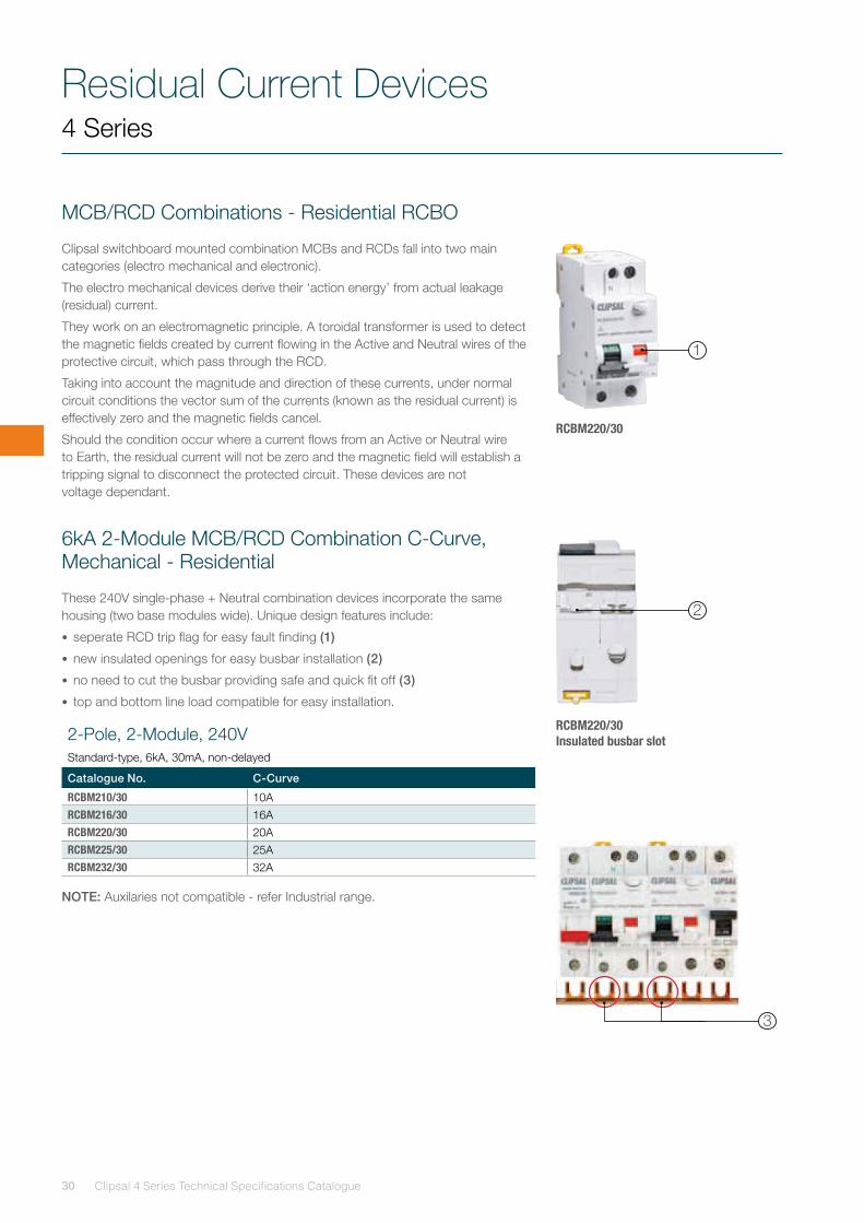
MCB/RCD Combinations - Residential RCBO
Clipsal switchboard mounted combination MCBs and RCDs fall into two main categories (electro mechanical and electronic).
The electro mechanical devices derive their ‘action energy’ from actual leakage (residual) current.
They work on an electromagnetic principle. A toroidal transformer is used to detect the magnetic fields created by current flowing in the Active and Neutral wires of the protective circuit, which pass through the RCD.
Taking into account the magnitude and direction of these currents, under normal circuit conditions the vector sum of the currents (known as the residual current) is effectively zero and the magnetic fields cancel.
Should the condition occur where a current flows from an Active or Neutral wire to Earth, the residual current will not be zero and the magnetic field will establish a tripping signal to disconnect the protected circuit. These devices are not voltage dependant.
6kA 2-Module MCB/RCD Combination C-Curve, Mechanical - Residential
These 240V single-phase + Neutral combination devices incorporate the same housing (two base modules wide). Unique design features include:
• seperate RCD trip flag for easy fault finding (1)
• new insulated openings for easy busbar installation (2)
• no need to cut the busbar providing safe and quick fit off (3)
• top and bottom line load compatible for easy installation.
NOTE: Auxilaries not compatible - refer Industrial range.
RCBM220/30
RCBM220/30 Insulated busbar slot
1
2
3
2-Pole, 2-Module, 240V Standard-type, 6kA, 30mA, non-delayed
Catalogue No. C-Curve
RCBM210/30 10ARCBM216/30 16ARCBM220/30 20ARCBM225/30 25ARCBM232/30 32A
Residual Current Devices 4 Series
31
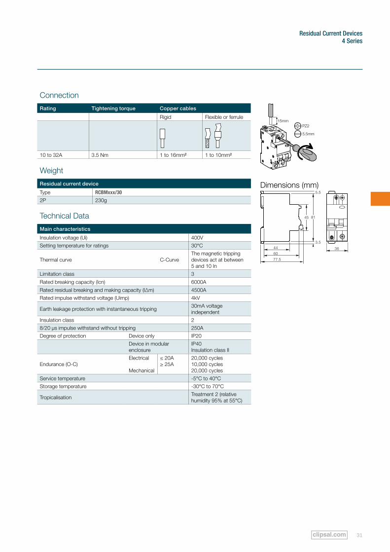
Connection
Rating Tightening torque Copper cables
Rigid Flexible or ferrule
10 to 32A 3.5 Nm 1 to 16mm² 1 to 10mm²
Weight
Residual current device
Type RCBMxxx/30
2P 230g
Technical Data
Main characteristics
Insulation voltage (Ui) 400VSetting temperature for ratings 30°C
Thermal curve C-CurveThe magnetic tripping devices act at between 5 and 10 In
Limitation class 3
Rated breaking capacity (Icn) 6000A
Rated residual breaking and making capacity (I∆m) 4500ARated impulse withstand voltage (Uimp) 4kV
Earth leakage protection with instantaneous tripping 30mA voltage independent
Insulation class 28/20 µs impulse withstand without tripping 250ADegree of protection Device only IP20
Device in modular enclosure
IP40 Insulation class II
Endurance (O-C)Electrical Mechanical
≤ 20A ≥ 25A
20,000 cycles 10,000 cycles 20,000 cycles
Service temperature -5°C to 40°CStorage temperature -30°C to 70°C
Tropicalisation Treatment 2 (relative humidity 95% at 55°C)
Dimensions (mm)
36
81
5.5
3.5
77.5
44
60
45
Residual Current Devices
Clipsal 4 Series Technical Specifications Catalogue32
4 Series
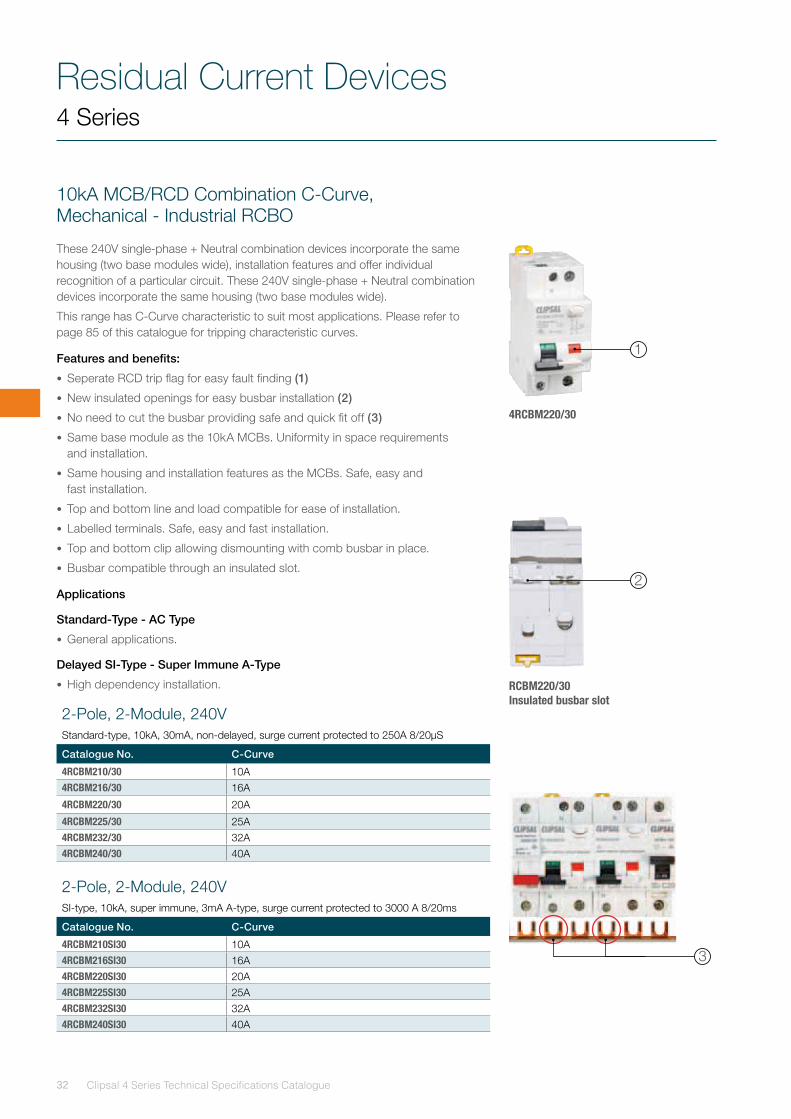
10kA MCB/RCD Combination C-Curve, Mechanical - Industrial RCBO
These 240V single-phase + Neutral combination devices incorporate the same housing (two base modules wide), installation features and offer individual recognition of a particular circuit. These 240V single-phase + Neutral combination devices incorporate the same housing (two base modules wide).
This range has C-Curve characteristic to suit most applications. Please refer to page 85 of this catalogue for tripping characteristic curves.
Features and benefits:
• Seperate RCD trip flag for easy fault finding (1)
• New insulated openings for easy busbar installation (2)
• No need to cut the busbar providing safe and quick fit off (3)
• Same base module as the 10kA MCBs. Uniformity in space requirements and installation.
• Same housing and installation features as the MCBs. Safe, easy and fast installation.
• Top and bottom line and load compatible for ease of installation.
• Labelled terminals. Safe, easy and fast installation.
• Top and bottom clip allowing dismounting with comb busbar in place.
• Busbar compatible through an insulated slot.
Applications
Standard-Type - AC Type
• General applications.
Delayed SI-Type - Super Immune A-Type
• High dependency installation.
2-Pole, 2-Module, 240V Standard-type, 10kA, 30mA, non-delayed, surge current protected to 250A 8/20µS
Catalogue No. C-Curve
4RCBM210/30 10A4RCBM216/30 16A
4RCBM220/30 20A
4RCBM225/30 25A4RCBM232/30 32A4RCBM240/30 40A
2-Pole, 2-Module, 240V SI-type, 10kA, super immune, 3mA A-type, surge current protected to 3000 A 8/20ms
Catalogue No. C-Curve
4RCBM210SI30 10A4RCBM216SI30 16A4RCBM220SI30 20A4RCBM225SI30 25A4RCBM232SI30 32A4RCBM240SI30 40A
RCBM220/30 Insulated busbar slot
2
4RCBM220/30
1
3
Residual Current Devices 4 Series
33
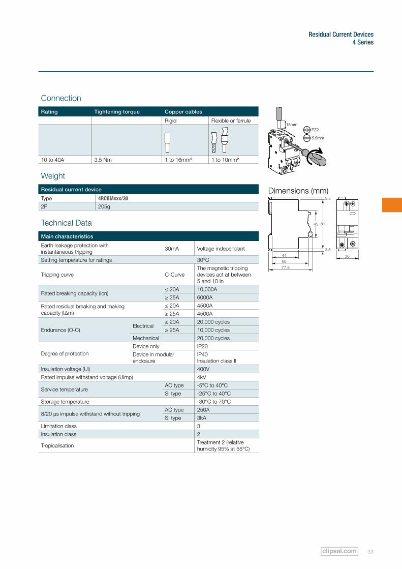
Weight
Residual current device
Type 4RCBMxxx/30
2P 205g
Dimensions (mm)
36
81
5.5
3.5
77.5
44
60
45Technical Data
Main characteristics
Earth leakage protection with instantaneous tripping 30mA Voltage independant
Setting temperature for ratings 30°C
Tripping curve C-CurveThe magnetic tripping devices act at between 5 and 10 In
Rated breaking capacity (Icn)≤ 20A 10,000A≥ 25A 6000A
Rated residual breaking and making capacity (I∆m)
≤ 20A 4500A≥ 25A 4500A
Endurance (O-C)Electrical
≤ 20A 20,000 cycles≥ 25A 10,000 cycles
Mechanical 20,000 cycles
Degree of protectionDevice only IP20Device in modular enclosure
IP40 Insulation class II
Insulation voltage (Ui) 400VRated impulse withstand voltage (Uimp) 4kV
Service temperatureAC type -5°C to 40°CSI type -25°C to 40°C
Storage temperature -30°C to 70°C
8/20 µs impulse withstand without trippingAC type 250ASI type 3kA
Limitation class 3Insulation class 2
Tropicalisation Treatment 2 (relative humidity 95% at 55°C)
Connection
Rating Tightening torque Copper cables
Rigid Flexible or ferrule
10 to 40A 3.5 Nm 1 to 16mm² 1 to 10mm²
Residual Current Devices
Clipsal 4 Series Technical Specifications Catalogue34
4 Series
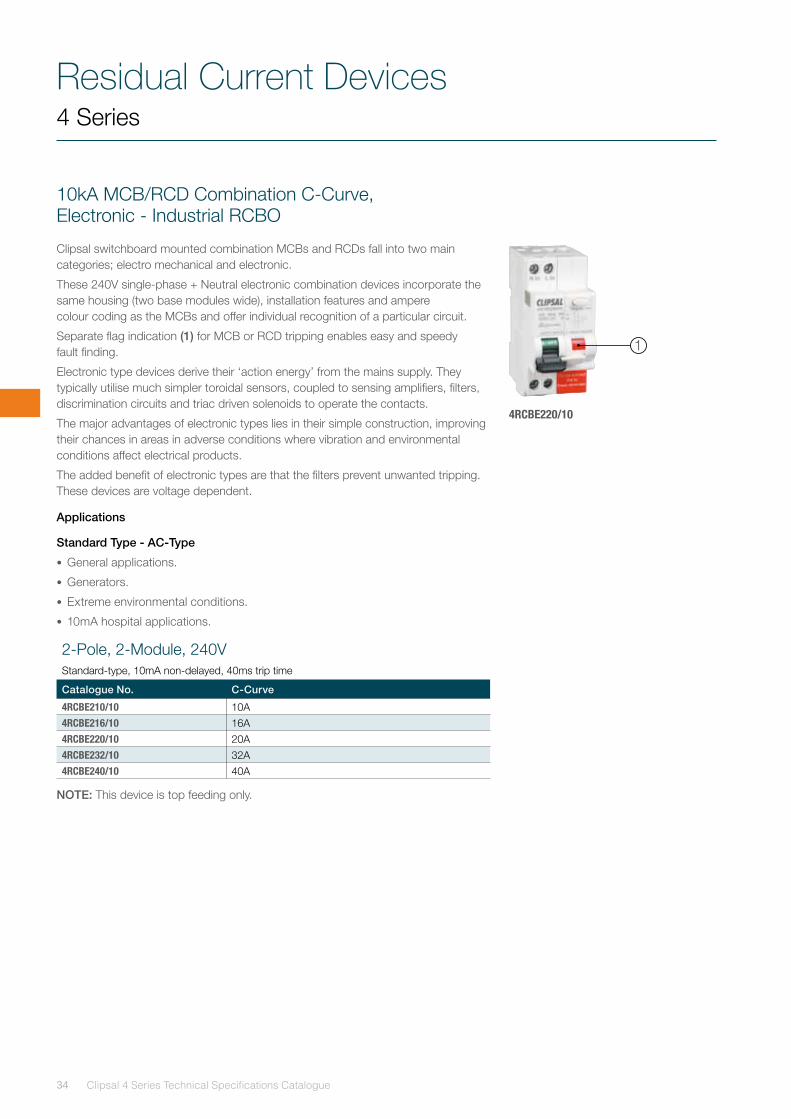
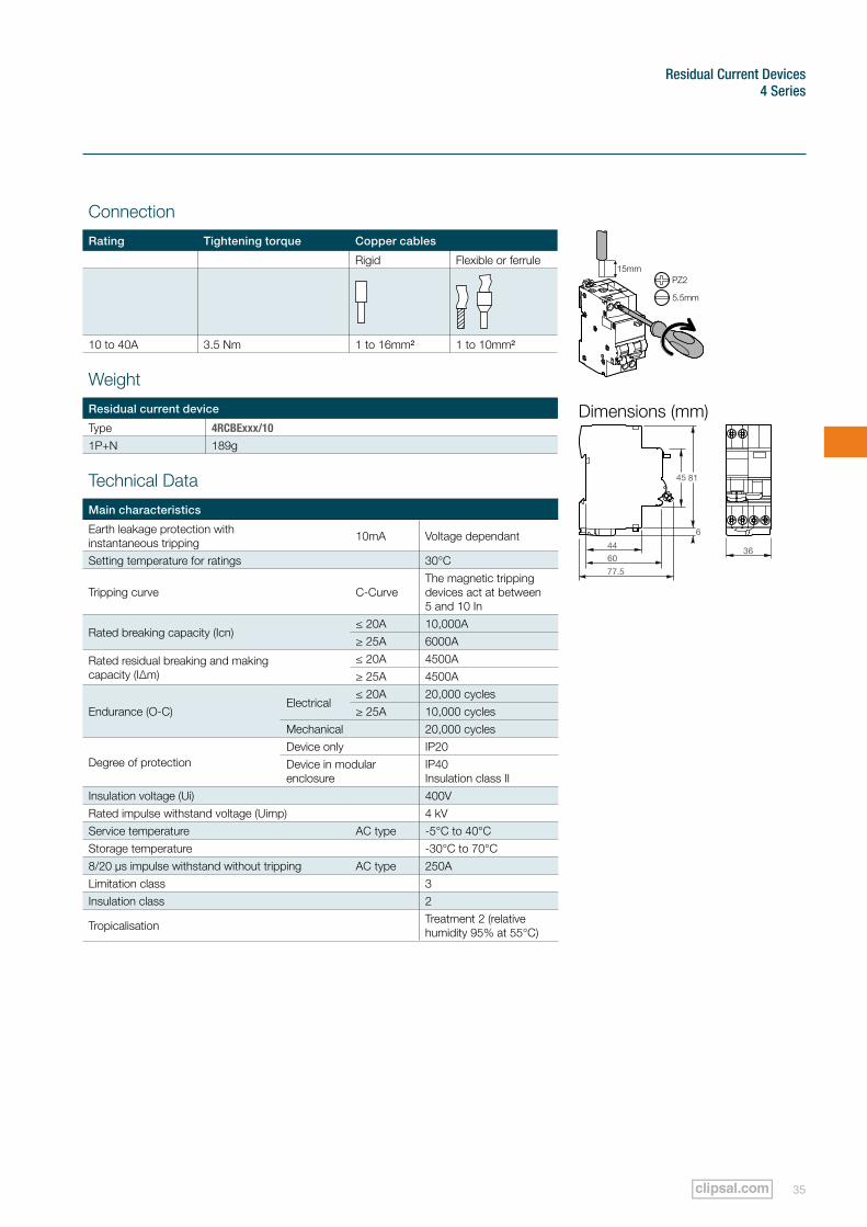
10kA MCB/RCD Combination C-Curve, Electronic - Industrial RCBO
Clipsal switchboard mounted combination MCBs and RCDs fall into two main categories; electro mechanical and electronic.
These 240V single-phase + Neutral electronic combination devices incorporate the same housing (two base modules wide), installation features and ampere colour coding as the MCBs and offer individual recognition of a particular circuit.
Separate flag indication (1) for MCB or RCD tripping enables easy and speedy fault finding.
Electronic type devices derive their ‘action energy’ from the mains supply. They typically utilise much simpler toroidal sensors, coupled to sensing amplifiers, filters, discrimination circuits and triac driven solenoids to operate the contacts.
The major advantages of electronic types lies in their simple construction, improving their chances in areas in adverse conditions where vibration and environmental conditions affect electrical products.
The added benefit of electronic types are that the filters prevent unwanted tripping. These devices are voltage dependent.
Applications
Standard Type - AC-Type
• General applications.
• Generators.
• Extreme environmental conditions.
• 10mA hospital applications.
2-Pole, 2-Module, 240V Standard-type, 10mA non-delayed, 40ms trip time
Catalogue No. C-Curve
4RCBE210/10 10A4RCBE216/10 16A4RCBE220/10 20A4RCBE232/10 32A4RCBE240/10 40A
NOTE: This device is top feeding only.
4RCBE220/10
1
Residual Current Devices 4 Series
35
Weight
Residual current device
Type 4RCBExxx/10
1P+N 189g
Technical Data
Main characteristics
Earth leakage protection with instantaneous tripping 10mA Voltage dependant
Setting temperature for ratings 30°C
Tripping curve C-CurveThe magnetic tripping devices act at between 5 and 10 In
Rated breaking capacity (Icn)≤ 20A 10,000A≥ 25A 6000A
Rated residual breaking and making capacity (I∆m)
≤ 20A 4500A≥ 25A 4500A
Endurance (O-C)Electrical
≤ 20A 20,000 cycles≥ 25A 10,000 cycles
Mechanical 20,000 cycles
Degree of protectionDevice only IP20Device in modular enclosure
IP40 Insulation class II
Insulation voltage (Ui) 400VRated impulse withstand voltage (Uimp) 4 kVService temperature AC type -5°C to 40°CStorage temperature -30°C to 70°C8/20 µs impulse withstand without tripping AC type 250ALimitation class 3Insulation class 2
Tropicalisation Treatment 2 (relative humidity 95% at 55°C)
Dimensions (mm)
81
6
77.5
44
60
45
36
Connection
Rating Tightening torque Copper cables
Rigid Flexible or ferrule
10 to 40A 3.5 Nm 1 to 16mm² 1 to 10mm²
Residual Current Devices
Clipsal 4 Series Technical Specifications Catalogue36
4 Series
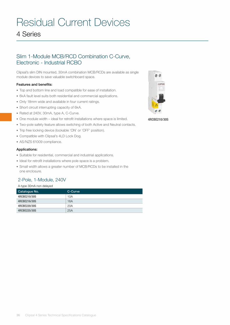
Slim 1-Module MCB/RCD Combination C-Curve, Electronic - Industrial RCBO
Clipsal’s slim DIN mounted, 30mA combination MCB/RCDs are available as single module devices to save valuable switchboard space.
Features and benefits:
• Top and bottom line and load compatible for ease of installation.
• 6kA fault level suits both residential and commercial applications.
• Only 18mm wide and available in four current ratings.
• Short circuit interrupting capacity of 6kA.
• Rated at 240V, 30mA, type A, C-Curve.
• One module width – ideal for retrofit installations where space is limited.
• Two-pole safety feature allows switching of both Active and Neutral contacts.
• Trip free locking device (lockable ‘ON’ or ‘OFF’ position).
• Compatible with Clipsal’s 4LD Lock Dog.
• AS/NZS 61009 compliance.
Applications:
• Suitable for residential, commercial and industrial applications.
• Ideal for retrofit installations where pole space is a problem.
• Small width allows a greater number of MCB/RCDs to be installed in the one enclosure.
2-Pole, 1-Module, 240V A-type 30mA non delayed
Catalogue No. C-Curve
4RCBE210/30S 10A4RCBE216/30S 16A4RCBE220/30S 20A4RCBE225/30S 25A
4RCBE210/30S
Residual Current Devices 4 Series
37
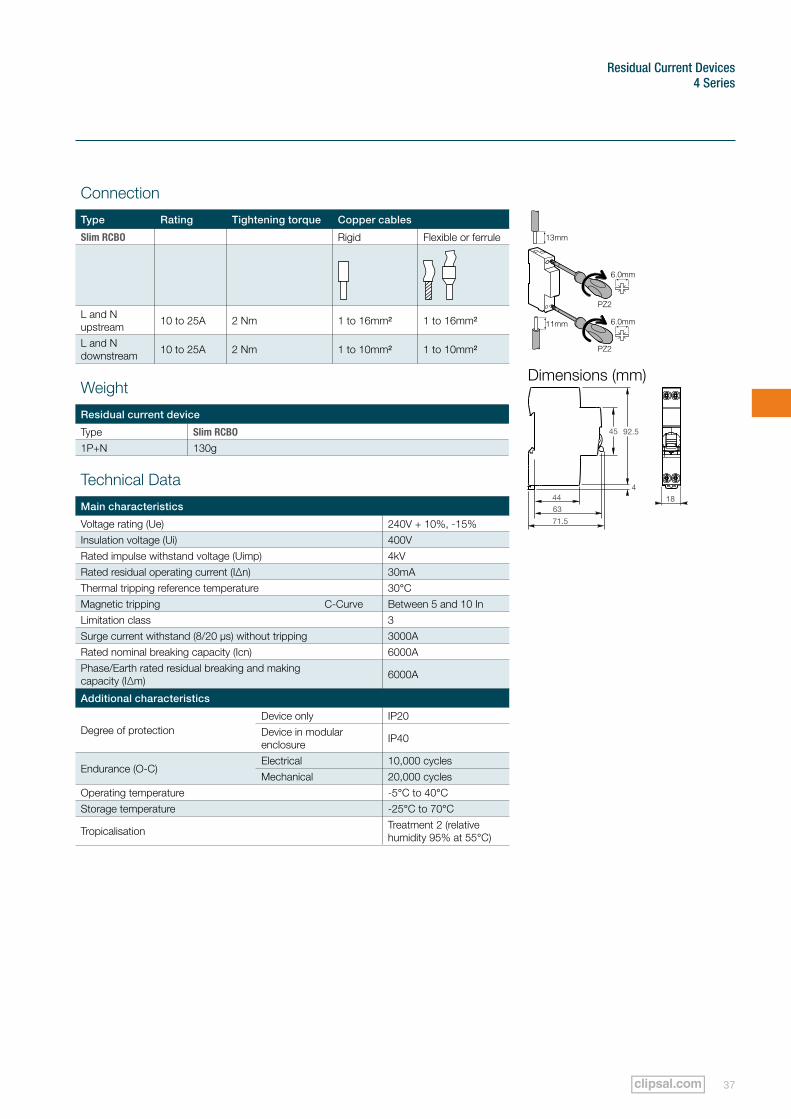
Connection
Type Rating Tightening torque Copper cables
Slim RCBO Rigid Flexible or ferrule
L and N upstream 10 to 25A 2 Nm 1 to 16mm² 1 to 16mm²
L and N downstream 10 to 25A 2 Nm 1 to 10mm² 1 to 10mm²
Weight
Residual current device
Type Slim RCBO
1P+N 130g
Dimensions (mm)
18
92.5
4
71.5
44
63
45
Technical Data
Main characteristics
Voltage rating (Ue) 240V + 10%, -15%Insulation voltage (Ui) 400VRated impulse withstand voltage (Uimp) 4kVRated residual operating current (I∆n) 30mAThermal tripping reference temperature 30°CMagnetic tripping C-Curve Between 5 and 10 InLimitation class 3Surge current withstand (8/20 µs) without tripping 3000ARated nominal breaking capacity (Icn) 6000APhase/Earth rated residual breaking and making capacity (I∆m) 6000A
Additional characteristics
Degree of protectionDevice only IP20Device in modular enclosure IP40
Endurance (O-C)Electrical 10,000 cyclesMechanical 20,000 cycles
Operating temperature -5°C to 40°CStorage temperature -25°C to 70°C
Tropicalisation Treatment 2 (relative humidity 95% at 55°C)
Residual Current Devices
Clipsal 4 Series Technical Specifications Catalogue38
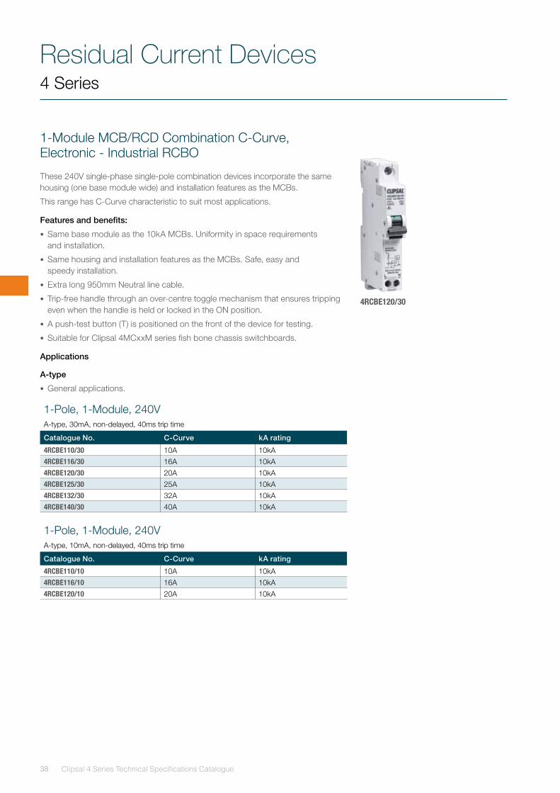
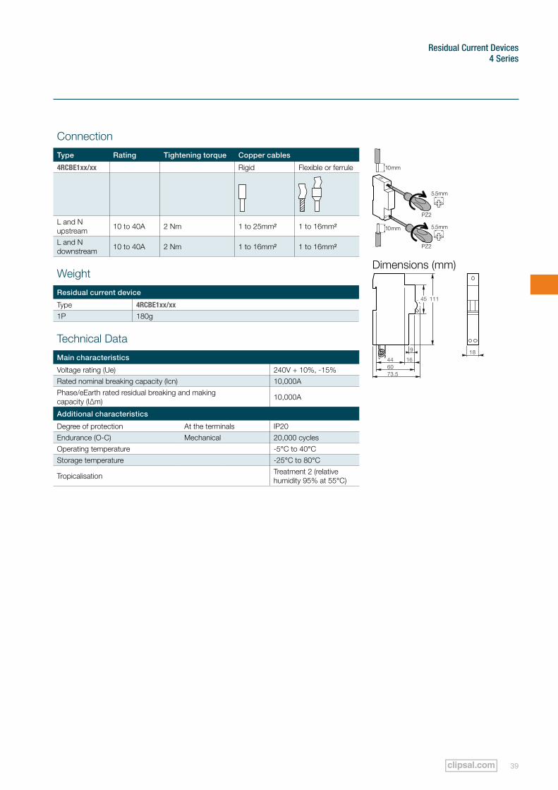
1-Module MCB/RCD Combination C-Curve, Electronic - Industrial RCBO
These 240V single-phase single-pole combination devices incorporate the same housing (one base module wide) and installation features as the MCBs.
This range has C-Curve characteristic to suit most applications.
Features and benefits:
• Same base module as the 10kA MCBs. Uniformity in space requirements and installation.
• Same housing and installation features as the MCBs. Safe, easy and speedy installation.
• Extra long 950mm Neutral line cable.
• Trip-free handle through an over-centre toggle mechanism that ensures tripping even when the handle is held or locked in the ON position.
• A push-test button (T) is positioned on the front of the device for testing.
• Suitable for Clipsal 4MCxxM series fish bone chassis switchboards.
Applications
A-type
• General applications.
4 Series
4RCBE120/30
1-Pole, 1-Module, 240V A-type, 30mA, non-delayed, 40ms trip time
Catalogue No. C-Curve kA rating
4RCBE110/30 10A 10kA4RCBE116/30 16A 10kA4RCBE120/30 20A 10kA4RCBE125/30 25A 10kA4RCBE132/30 32A 10kA4RCBE140/30 40A 10kA
1-Pole, 1-Module, 240V A-type, 10mA, non-delayed, 40ms trip time
Catalogue No. C-Curve kA rating
4RCBE110/10 10A 10kA4RCBE116/10 16A 10kA4RCBE120/10 20A 10kA
Residual Current Devices 4 Series
39
Dimensions (mm)
Connection
Type Rating Tightening torque Copper cables
4RCBE1xx/xx Rigid Flexible or ferrule
L and N upstream 10 to 40A 2 Nm 1 to 25mm² 1 to 16mm²
L and N downstream 10 to 40A 2 Nm 1 to 16mm² 1 to 16mm²
Weight
Residual current device
Type 4RCBE1xx/xx
1P 180g
Technical Data
Main characteristics
Voltage rating (Ue) 240V + 10%, -15%Rated nominal breaking capacity (Icn) 10,000APhase/eEarth rated residual breaking and making capacity (I∆m) 10,000A
Additional characteristics
Degree of protection At the terminals IP20Endurance (O-C) Mechanical 20,000 cyclesOperating temperature -5°C to 40°CStorage temperature -25°C to 80°C
Tropicalisation Treatment 2 (relative humidity 95% at 55°C)
18
111
44 16
9
6073.5
45
Residual Current Devices
Clipsal 4 Series Technical Specifications Catalogue40
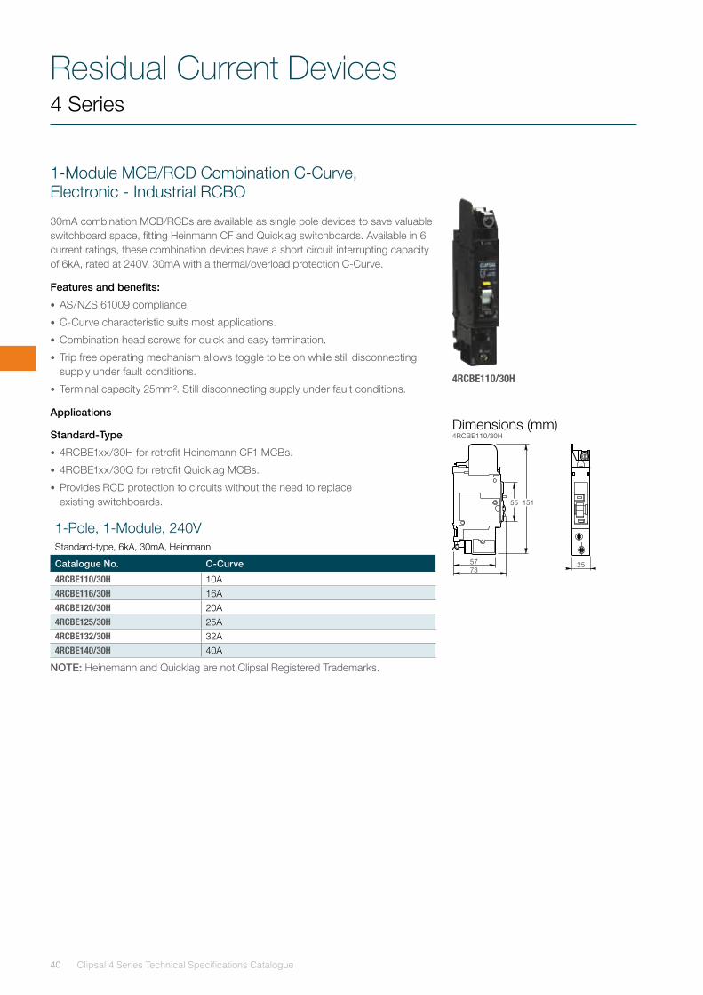
1-Module MCB/RCD Combination C-Curve, Electronic - Industrial RCBO
30mA combination MCB/RCDs are available as single pole devices to save valuable switchboard space, fitting Heinmann CF and Quicklag switchboards. Available in 6 current ratings, these combination devices have a short circuit interrupting capacity of 6kA, rated at 240V, 30mA with a thermal/overload protection C-Curve.
Features and benefits:
• AS/NZS 61009 compliance.
• C-Curve characteristic suits most applications.
• Combination head screws for quick and easy termination.
• Trip free operating mechanism allows toggle to be on while still disconnecting supply under fault conditions.
• Terminal capacity 25mm². Still disconnecting supply under fault conditions.
Applications
Standard-Type
• 4RCBE1xx/30H for retrofit Heinemann CF1 MCBs.
• 4RCBE1xx/30Q for retrofit Quicklag MCBs.
• Provides RCD protection to circuits without the need to replace existing switchboards.
NOTE: Heinemann and Quicklag are not Clipsal Registered Trademarks.
4 Series
4RCBE110/30H
1-Pole, 1-Module, 240V Standard-type, 6kA, 30mA, Heinmann
Catalogue No. C-Curve
4RCBE110/30H 10A4RCBE116/30H 16A4RCBE120/30H 20A4RCBE125/30H 25A4RCBE132/30H 32A4RCBE140/30H 40A
25
15155
5773
Dimensions (mm)4RCBE110/30H
Residual Current Devices 4 Series
41
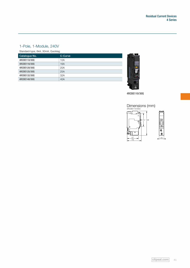
4RCBE110/30Q
1-Pole, 1-Module, 240V Standard-type, 6kA, 30mA, Quicklag
Catalogue No. C-Curve
4RCBE110/30Q 10A4RCBE116/30Q 16A4RCBE120/30Q 20A4RCBE125/30Q 25A4RCBE132/30Q 32A4RCBE140/30Q 40A
25
12873
5773
Dimensions (mm)4RCBE110/30Q
Clipsal 4 Series Technical Specifications Catalogue42
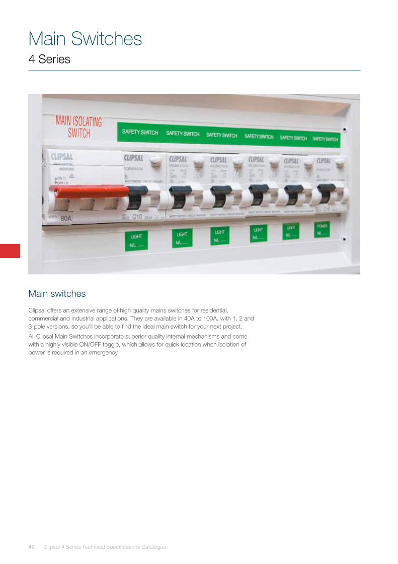
Main Switches
Main switches
Clipsal offers an extensive range of high quality mains switches for residential, commercial and industrial applications. They are available in 40A to 100A, with 1, 2 and 3-pole versions, so you’ll be able to find the ideal main switch for your next project.
All Clipsal Main Switches incorporate superior quality internal mechanisms and come with a highly visible ON/OFF toggle, which allows for quick location when isolation of power is required in an emergency.
4 Series
43
Main switches 4 Series

Clipsal 4 Series Technical Specifications Catalogue44
Main Switches4 Series
Isolating Switches, Residential
Isolating switches are available in 1, 2 and 3 pole models to 100 amps.
Features and benefits:
• Cable automatically guided to the correct position: terminals with guard.
• Insulated terminals - IP20.
• Downstream by bi-connect comb busbar, except 100A version.
• Downstream/upstream by tunnel terminals.
• Manual control on front face by O-I lever.
1-Pole, 1-Module, 240V
Catalogue No.
MSW140 40AMSW180 80AMSW1100 100A
2-Pole, 2-Module, 415V
Catalogue No.
MSW240 40AMSW280 80AMSW2100 100A
3-Pole, 3-Module, 415V
Catalogue No.
MSW340 40AMSW380 80AMSW3100 100A
MSW180
MSW280
MSW380

45
Main switches 4 Series
Connection
Type Rating Tightening torque Copper cables
Rigid Flexible or ferrule
Switch 40 to 100A 3.5 Nm ≤ 50mm² ≤ 35mm²
Weight
Isolator
Type MSWxxxx
1P 81g2P 161g3P 243g
Dimensions (mm) 40A & 80A
Dimensions (mm) 100A
81
2
78.5
44
73
45
82
75.5
40
60
45
1836
54
1836
54
Technical Data
Main characteristics 40A 80A 100A
Insulation voltage (Ui) 1P 250V a.c. 2P, 3P 500V a.c.
Pollution degree 3
Power circuit
Rated impulse withstand voltage (Uimp) 6kVOperating category a.c. - 22APermissible rated short-time withstand current (Icw) 1260A 1600A 2500AConditional rated short circuit current (Inc) 6 kA to AS/NZS 60947-3Rated short circuit closing current (Icm) 4.2kA 5kA
Using direct current 48V (110V with 2-poles in series)
Additional characteristics
Degree of protectionDevice only IP20Device in modular enclosure IP40
Endurance (O-C)Mechanical 50,000 cyclesElectrical 10,000 cycles
Operation temperature -20°C to 50°C
Storage temperature -40°C to 70°C
Tropicalisation Treatment 2 (relative humidity 95% at 55°C)
NOTE: 100A main switches are not bi-connect.
Clipsal 4 Series Technical Specifications Catalogue46
Main Switches4 Series
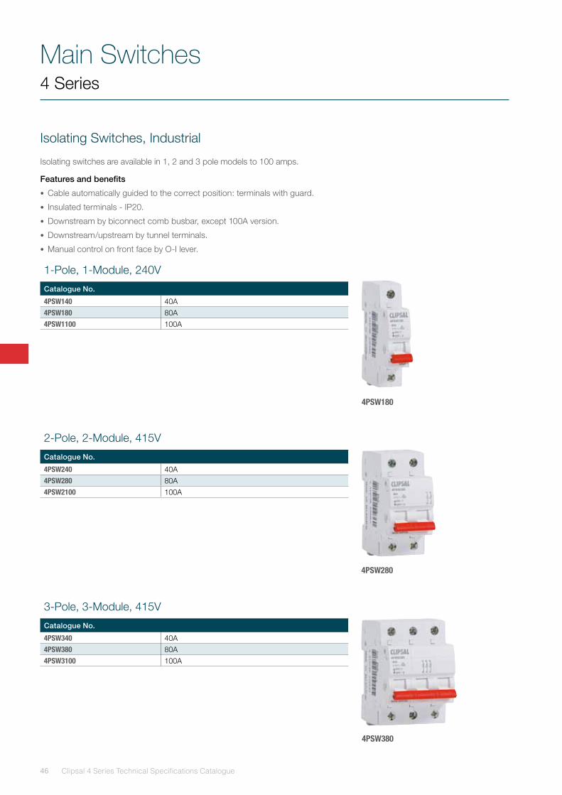
Isolating Switches, Industrial
Isolating switches are available in 1, 2 and 3 pole models to 100 amps.
Features and benefits
• Cable automatically guided to the correct position: terminals with guard.
• Insulated terminals - IP20.
• Downstream by biconnect comb busbar, except 100A version.
• Downstream/upstream by tunnel terminals.
• Manual control on front face by O-I lever.
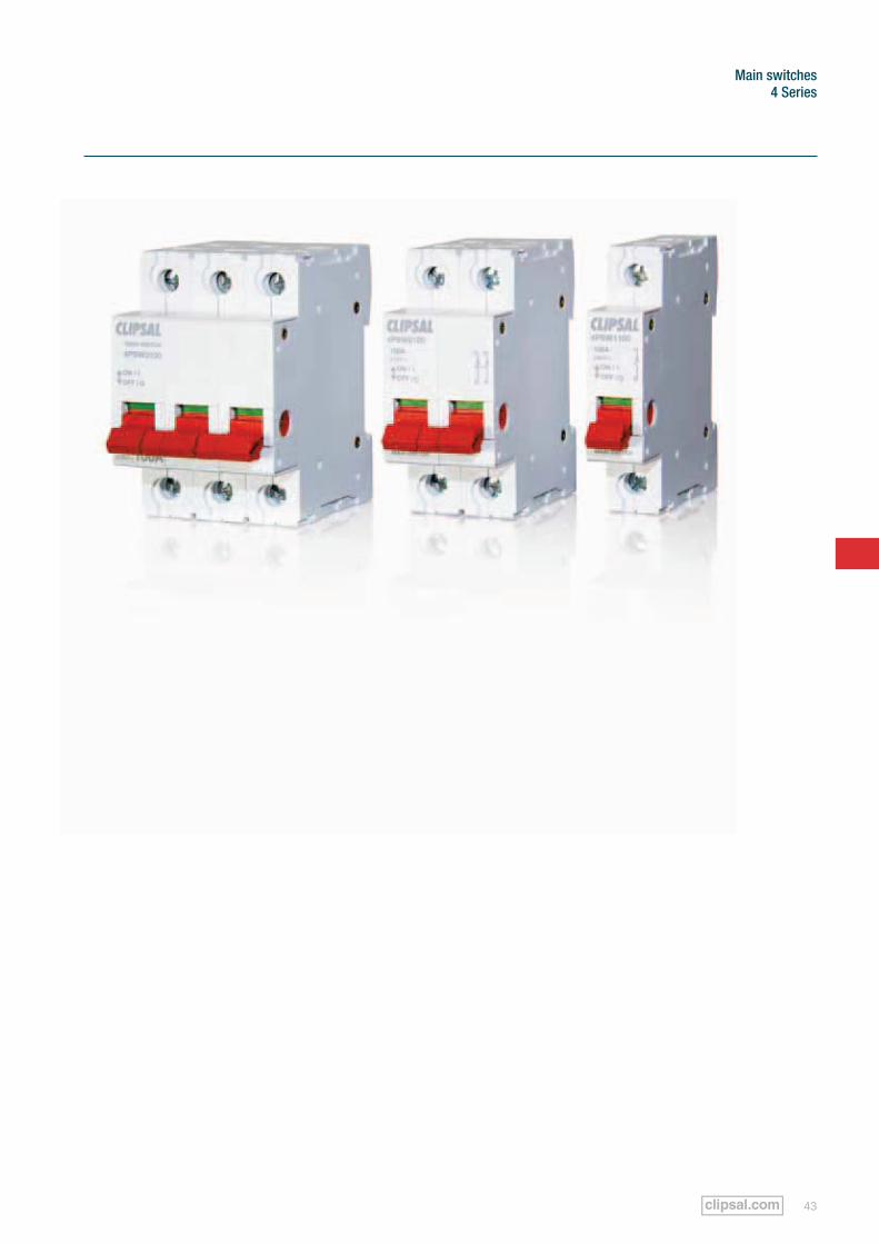
4PSW180
4PSW280
4PSW380
1-Pole, 1-Module, 240V
Catalogue No.
4PSW140 40A4PSW180 80A4PSW1100 100A
2-Pole, 2-Module, 415V
Catalogue No.
4PSW240 40A4PSW280 80A4PSW2100 100A
3-Pole, 3-Module, 415V
Catalogue No.
4PSW340 40A4PSW380 80A4PSW3100 100A
47
Main switches 4 Series
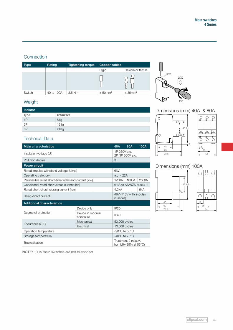
Connection
Type Rating Tightening torque Copper cables
Rigid Flexible or ferrule
Switch 40 to 100A 3.5 Nm ≤ 50mm² ≤ 35mm²
Dimensions (mm) 40A & 80A
Dimensions (mm) 100A
81
2
78.5
44
73
45
82
75.5
40
60
45
1836
54
1836
54
Weight
Isolator
Type 4PSWxxxx
1P 81g2P 161g3P 243g
Technical Data
Main characteristics 40A 80A 100A
Insulation voltage (Ui) 1P 250V a.c. 2P, 3P 500V a.c.
Pollution degree 3
Power circuit
Rated impulse withstand voltage (Uimp) 6kVOperating category a.c. - 22APermissible rated short-time withstand current (Icw) 1260A 1600A 2500AConditional rated short circuit current (Inc) 6 kA to AS/NZS 60947-3Rated short circuit closing current (Icm) 4.2kA 5kA
Using direct current 48V (110V with 2-poles in series)
Additional characteristics
Degree of protectionDevice only IP20Device in modular enclosure IP40
Endurance (O-C)Mechanical 50,000 cyclesElectrical 10,000 cycles
Operation temperature -20°C to 50°C
Storage temperature -40°C to 70°C
Tropicalisation Treatment 2 (relative humidity 95% at 55°C)
NOTE: 100A main switches are not bi-connect.
Accessories
Clipsal 4 Series Technical Specifications Catalogue48
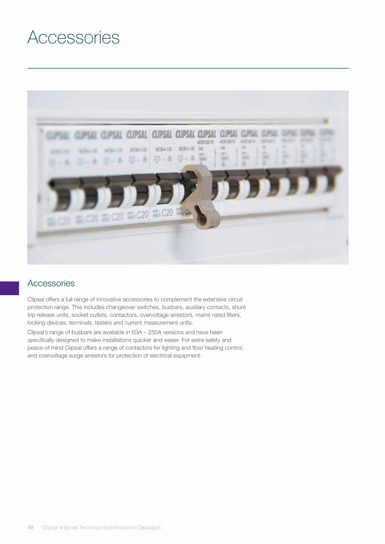
Accessories
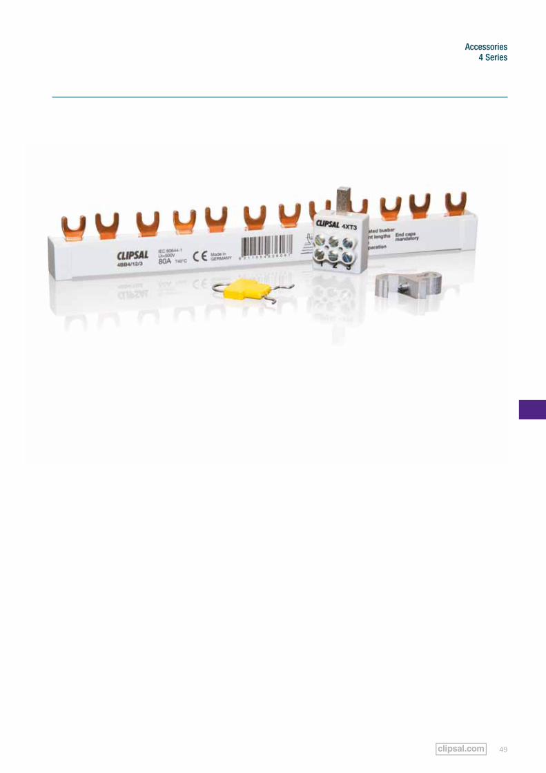
Clipsal offers a full range of innovative accessories to complement the extensive circuit protection range. This includes changeover switches, busbars, auxiliary contacts, shunt trip release units, socket outlets, contactors, overvoltage arrestors, mains rated filters, locking devices, terminals, testers and current measurement units.
Clipsal’s range of busbars are available in 63A – 250A versions and have been specifically designed to make installations quicker and easier. For extra safety and peace of mind Clipsal offers a range of contactors for lighting and floor heating control, and overvoltage surge arrestors for protection of electrical equipment.
49
Accessories4 Series
Accessories
Clipsal 4 Series Technical Specifications Catalogue50
4 Series
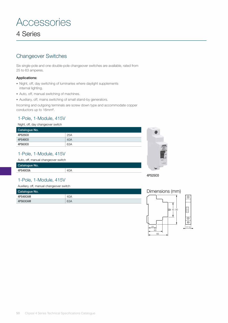
Changeover Switches
Six single-pole and one double-pole changeover switches are available, rated from 25 to 63 amperes.
Applications:
• Night, off, day switching of luminaries where daylight supplements internal lighting.
• Auto, off, manual switching of machines.
• Auxiliary, off, mains switching of small stand-by generators.
Incoming and outgoing terminals are screw down type and accommodate copper conductors up to 16mm².
4PS25CO
1-Pole, 1-Module, 415V Night, off, day changeover switch
Catalogue No.
4PS25CO 25A4PS40CO 40A4PS63CO 63A
1-Pole, 1-Module, 415V Auto, off, manual changeover switch
Catalogue No.
4PS40COA 40A
1-Pole, 1-Module, 415V Auxiliary, off, manual changeover switch
Catalogue No.
4PS40CAM 40A4PS63CAM 63A
90
60
25
40
45
17.5
Dimensions (mm)
51
Accessories4 Series
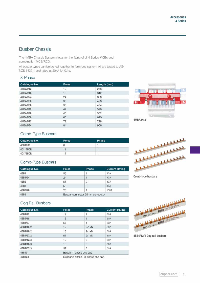
Busbar Chassis
The 4MBA Chassis System allows for the fitting of all 4 Series MCBs and combination MCB/RCD.
All busbar types can be bolted together to form one system. All are tested to AS/NZS 3439.1 and rated at 20kA for 0.1s.
4MBA3/18
3-Phase
Catalogue No. Poles Length (mm)
4MBA3/12 12 258
4MBA3/18 18 3124MBA3/24 24 3664MBA3/30 30 4204MBA3/36 36 4744MBA3/42 42 5284MBA3/48 48 5824MBA3/60 60 6904MBA3/72 72 7984MBA3/84 84 906
Comb-Type Busbars
Catalogue No. Poles Phase
4C6BBCR 6 1
4C11BBCR 11 1
4C17BBCR 17 1
Comb-Type Busbars
Catalogue No. Poles Phase Current Rating
4BB1 56 1 80A
4BB1/24 24 1 80A
4BB2 56 2 80A
4BB3 56 3 80A
4BB5/26 26 1 100A
4BB5 Busbar connector 25mm conductor
Cog Rail Busbars
Catalogue No. Poles Phase Current Rating
4BB4/12 12 1 80A
4BB4/18 18 1 80A
4BB4/57 57 1 80A
4BB4/12/2 12 2/1+N 80A
4BB4/18/2 18 2/1+N 80A
4BB4/57/2 57 2/1+N 80A
4BB4/12/3 12 3 80A
4BB4/18/3 18 3 80A
4BB4/57/3 57 3 80A
4BBTC1 Busbar 1-phase end cap
4BBTC3 Busbar 2-phase - 3-phase end cap
Comb-type busbars
4BB4/12/2 Cog rail busbars
Accessories
Clipsal 4 Series Technical Specifications Catalogue52
4 Series
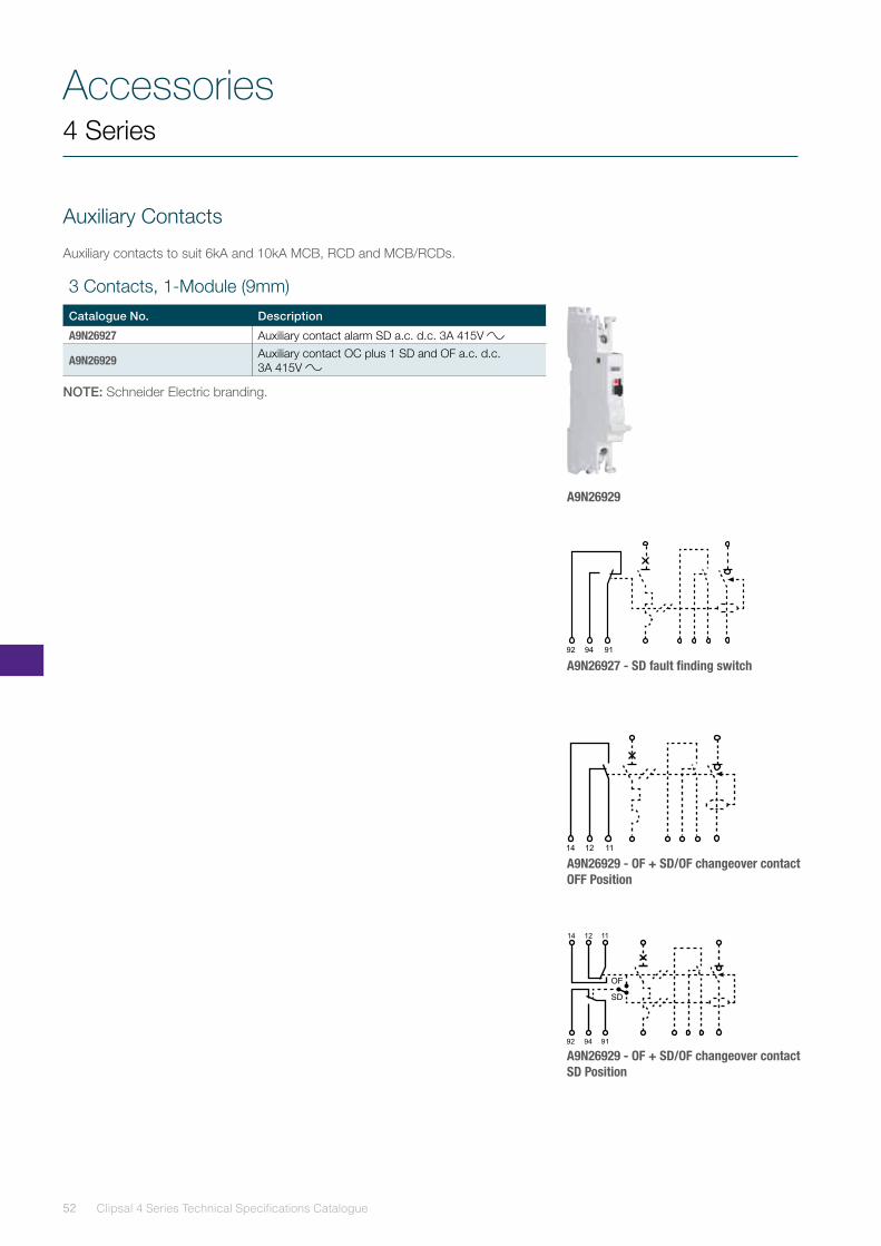
Auxiliary Contacts
Auxiliary contacts to suit 6kA and 10kA MCB, RCD and MCB/RCDs.
A9N26929
A9N26927 - SD fault finding switch
A9N26929 - OF + SD/OF changeover contact OFF Position
A9N26929 - OF + SD/OF changeover contact SD Position
3 Contacts, 1-Module (9mm)
Catalogue No. Description
A9N26927 Auxiliary contact alarm SD a.c. d.c. 3A 415V
A9N26929 Auxiliary contact OC plus 1 SD and OF a.c. d.c. 3A 415V
NOTE: Schneider Electric branding.
53
Accessories4 Series
Shunt Trip Release Units
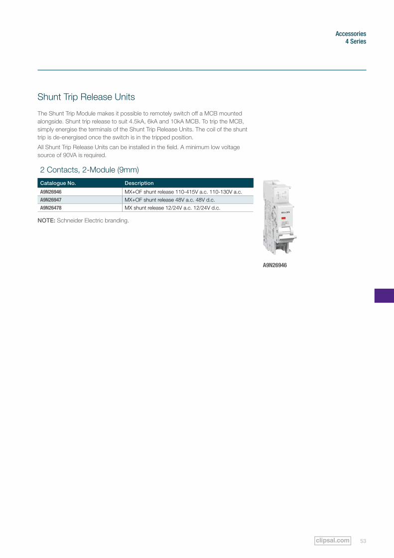
The Shunt Trip Module makes it possible to remotely switch off a MCB mounted alongside. Shunt trip release to suit 4.5kA, 6kA and 10kA MCB. To trip the MCB, simply energise the terminals of the Shunt Trip Release Units. The coil of the shunt trip is de-energised once the switch is in the tripped position.
All Shunt Trip Release Units can be installed in the field. A minimum low voltage source of 90VA is required.
2 Contacts, 2-Module (9mm)
Catalogue No. Description
A9N26946 MX+OF shunt release 110-415V a.c. 110-130V a.c.A9N26947 MX+OF shunt release 48V a.c. 48V d.c.A9N26478 MX shunt release 12/24V a.c. 12/24V d.c.
A9N26946
NOTE: Schneider Electric branding.
Accessories
Clipsal 4 Series Technical Specifications Catalogue54
4 Series
Socket Outlets
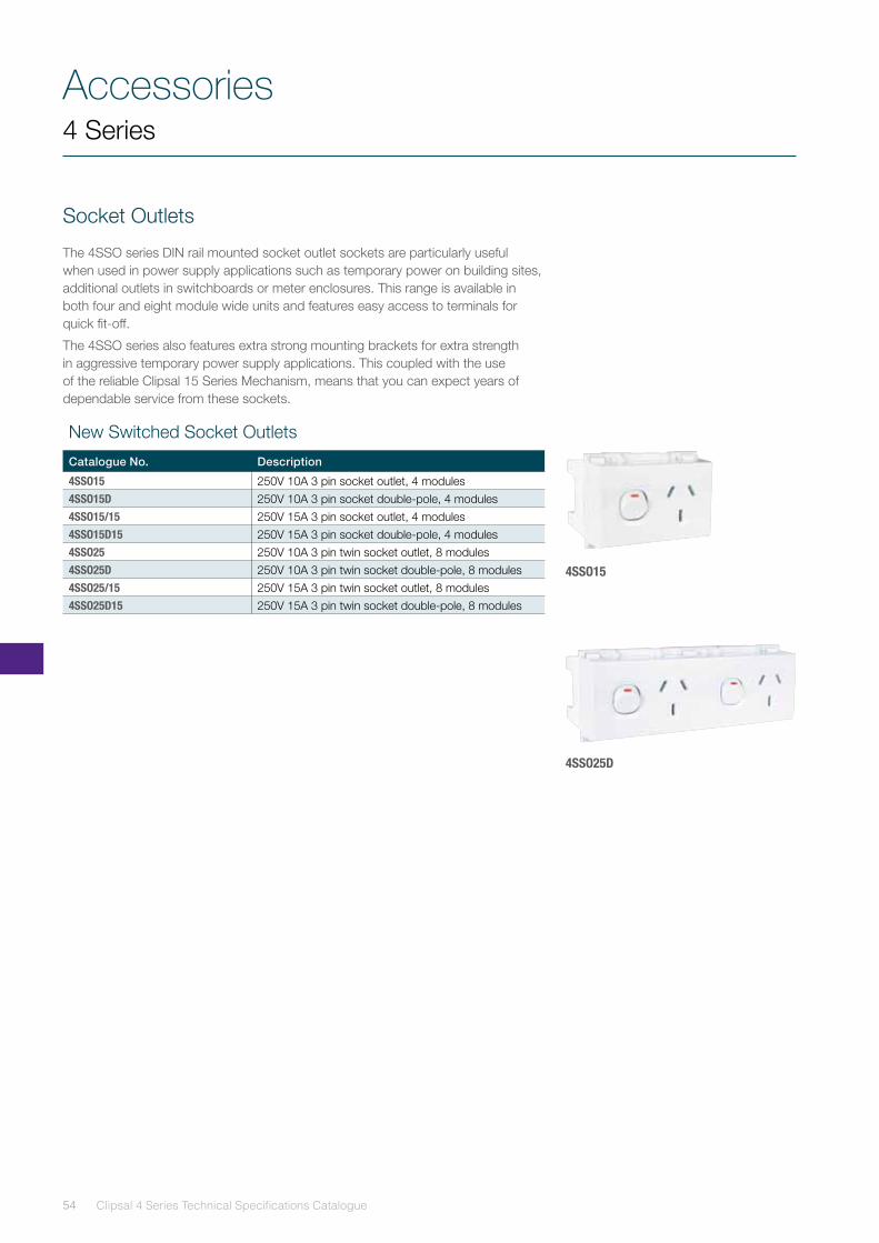
The 4SSO series DIN rail mounted socket outlet sockets are particularly useful when used in power supply applications such as temporary power on building sites, additional outlets in switchboards or meter enclosures. This range is available in both four and eight module wide units and features easy access to terminals for quick fit-off.
The 4SSO series also features extra strong mounting brackets for extra strength in aggressive temporary power supply applications. This coupled with the use of the reliable Clipsal 15 Series Mechanism, means that you can expect years of dependable service from these sockets.
New Switched Socket Outlets
Catalogue No. Description
4SSO15 250V 10A 3 pin socket outlet, 4 modules4SSO15D 250V 10A 3 pin socket double-pole, 4 modules4SSO15/15 250V 15A 3 pin socket outlet, 4 modules4SSO15D15 250V 15A 3 pin socket double-pole, 4 modules4SSO25 250V 10A 3 pin twin socket outlet, 8 modules4SSO25D 250V 10A 3 pin twin socket double-pole, 8 modules4SSO25/15 250V 15A 3 pin twin socket outlet, 8 modules4SSO25D15 250V 15A 3 pin twin socket double-pole, 8 modules
4SSO15
4SSO25D
55
Accessories4 Series
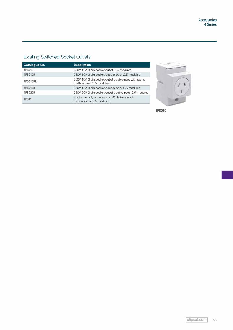
Existing Switched Socket Outlets
Catalogue No. Description
4PSO10 250V 10A 3 pin socket outlet, 2.5 modules4PSO10D 250V 10A 3 pin socket double-pole, 2.5 modules
4PSO10DL 250V 10A 3 pin socket outlet double-pole with round Earth socket, 2.5 modules
4PSO15D 250V 15A 3 pin socket double-pole, 2.5 modules4PSO20D 250V 20A 3 pin socket outlet double-pole, 2.5 modules
4PS31 Enclosure only accepts any 30 Series switch mechanisms, 2.5 modules
4PSO10
Accessories
Clipsal 4 Series Technical Specifications Catalogue56
4 Series
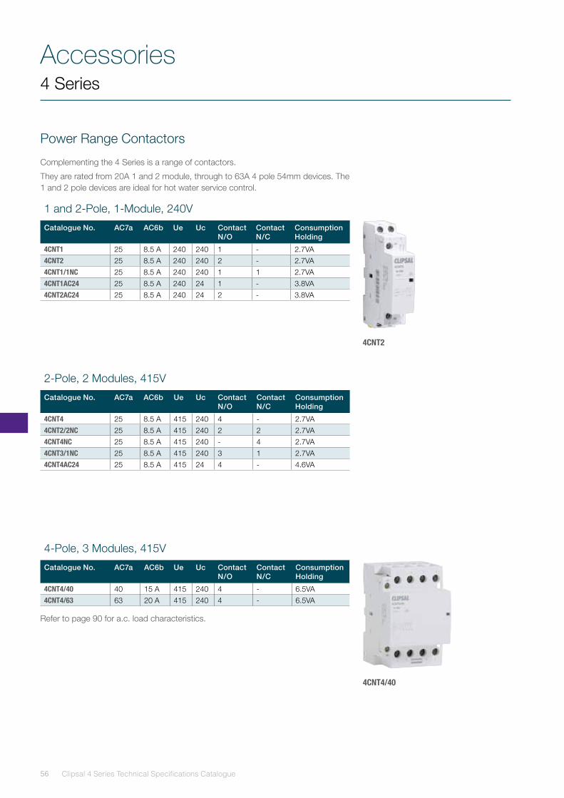
Power Range Contactors
Complementing the 4 Series is a range of contactors.
They are rated from 20A 1 and 2 module, through to 63A 4 pole 54mm devices. The 1 and 2 pole devices are ideal for hot water service control.
4CNT2
4CNT4/40
1 and 2-Pole, 1-Module, 240V
Catalogue No. AC7a AC6b Ue Uc Contact N/O
Contact N/C
Consumption Holding
4CNT1 25 8.5 A 240 240 1 - 2.7VA4CNT2 25 8.5 A 240 240 2 - 2.7VA4CNT1/1NC 25 8.5 A 240 240 1 1 2.7VA4CNT1AC24 25 8.5 A 240 24 1 - 3.8VA4CNT2AC24 25 8.5 A 240 24 2 - 3.8VA
2-Pole, 2 Modules, 415V
Catalogue No. AC7a AC6b Ue Uc Contact N/O
Contact N/C
Consumption Holding
4CNT4 25 8.5 A 415 240 4 - 2.7VA4CNT2/2NC 25 8.5 A 415 240 2 2 2.7VA4CNT4NC 25 8.5 A 415 240 - 4 2.7VA4CNT3/1NC 25 8.5 A 415 240 3 1 2.7VA4CNT4AC24 25 8.5 A 415 24 4 - 4.6VA
4-Pole, 3 Modules, 415V
Catalogue No. AC7a AC6b Ue Uc Contact N/O
Contact N/C
Consumption Holding
4CNT4/40 40 15 A 415 240 4 - 6.5VA4CNT4/63 63 20 A 415 240 4 - 6.5VA
Refer to page 90 for a.c. load characteristics.
57
Accessories4 Series
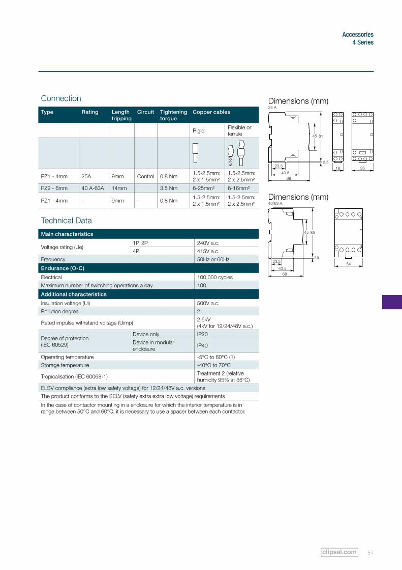
Connection
Type Rating Length tripping
Circuit Tightening torque
Copper cables
Rigid Flexible or ferrule
PZ1 - 4mm 25A 9mm Control 0.8 Nm 1.5-2.5mm: 2 x 1.5mm²
1.5-2.5mm: 2 x 2.5mm²
PZ2 - 6mm 40 A-63A 14mm 3.5 Nm 6-25mm² 6-16mm²
PZ1 - 4mm - 9mm - 0.8 Nm 1.5-2.5mm: 2 x 1.5mm²
1.5-2.5mm: 2 x 2.5mm²
Technical Data
Main characteristics
Voltage rating (Ue)1P, 2P 240V a.c.4P 415V a.c.
Frequency 50Hz or 60Hz
Endurance (O-C)
Electrical 100,000 cyclesMaximum number of switching operations a day 100
Additional characteristics
Insulation voltage (Ui) 500V a.c.Pollution degree 2
Rated impulse withstand voltage (Uimp) 2.5kV (4kV for 12/24/48V a.c.)
Degree of protection (IEC 60529)
Device only IP20Device in modular enclosure IP40
Operating temperature -5°C to 60°C (1)Storage temperature -40°C to 70°C
Tropicalisation (IEC 60068-1) Treatment 2 (relative humidity 95% at 55°C)
ELSV compliance (extra low safety voltage) for 12/24/48V a.c. versionsThe product conforms to the SELV (safety extra extra low voltage) requirements
In the case of contactor mounting in a enclosure for which the interior temperature is in range between 50°C and 60°C, it is necessary to use a spacer between each contactor.
Dimensions (mm)
Dimensions (mm)
25 A
40/63 A
81
2.5
68
23.5
43.5
45
18
85
2.5
68
23.5
43.5
45
54
36
Accessories
Clipsal 4 Series Technical Specifications Catalogue58
4 Series
Installation (Relay) Power Range Contactors, Series Z7
These switching devices have been designed specifically for installation in modular distribution with or without doors. Innovative technology using a.c. magnets are used for switching the contactors. This reduces the level of audible noise, while ensuring reliability and high contact forces in a device utilising a small footprint. The benefits of these characteristics enable the contactors to meet the stringent application requirements on systems, office equipment and residential areas.
The installation (relay) contactors are suitable for 1-phase or 3-phase consumer units up to 63A. A vast range of these devices are available for applications in building management and control.
Use of power range contactors from 16 to 63 A
For automation needs in housing, tertiary and industrial sectors. The range of modular CT contactors are used for:
• power control of final circuits for housing and tertiary sectors:
•lighting (luminous signs, shop windows, safety lighting, etc.)
•heating, heat pumps, ovens
•hot water for domestic use
•small utility motors (pumps, fans, barriers, garage doors, etc.)
•emergency stops and safety systems
•air conditioning
• energy distribution control:
•load shedding and restoration
•source changeover, etc.
59
Accessories4 Series
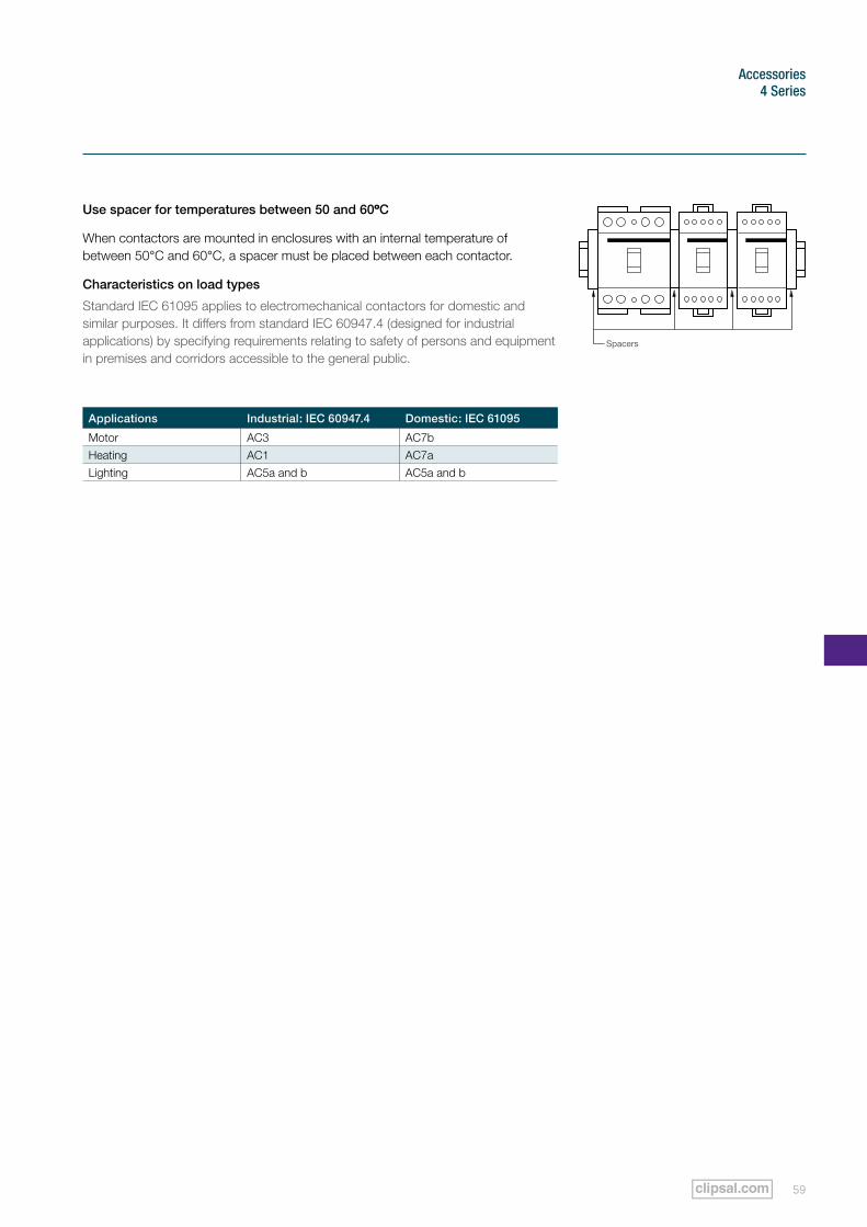
Use spacer for temperatures between 50 and 60ºC
When contactors are mounted in enclosures with an internal temperature of between 50°C and 60°C, a spacer must be placed between each contactor.
Characteristics on load types
Standard IEC 61095 applies to electromechanical contactors for domestic and similar purposes. It differs from standard IEC 60947.4 (designed for industrial applications) by specifying requirements relating to safety of persons and equipment in premises and corridors accessible to the general public.
Applications Industrial: IEC 60947.4 Domestic: IEC 61095
Motor AC3 AC7bHeating AC1 AC7aLighting AC5a and b AC5a and b
Spacers
Accessories - Surge Protection
Clipsal 4 Series Product Overview Catalogue60
4 Series
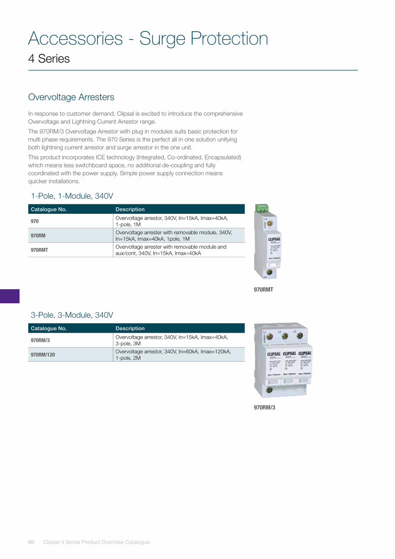
Overvoltage Arresters
In response to customer demand, Clipsal is excited to introduce the comprehensive Overvoltage and Lightning Current Arrestor range.
The 970RM/3 Overvoltage Arrestor with plug in modules suits basic protection for multi phase requirements. The 970 Series is the perfect all in one solution unifying both lightning current arrestor and surge arrestor in the one unit.
This product incorporates ICE technology (Integrated, Co-ordinated, Encapsulated) which means less switchboard space, no additional de-coupling and fully coordinated with the power supply. Simple power supply connection means quicker installations.
970RMT
970RM/3
1-Pole, 1-Module, 340V
Catalogue No. Description
970 Overvoltage arrestor, 340V, In=15kA, Imax=40kA, 1-pole, 1M
970RM Overvoltage arrester with removable module, 340V,In=15kA, Imax=40kA, 1pole, 1M
970RMT Overvoltage arrester with removable module and aux/cont, 340V, In=15kA, Imax=40kA
3-Pole, 3-Module, 340V
Catalogue No. Description
970RM/3 Overvoltage arrestor, 340V, In=15kA, Imax=40kA, 3-pole, 3M
970RM/120 Overvoltage arrestor, 340V, In=60kA, Imax=120kA, 1-pole, 2M
61
Accessories4 Series
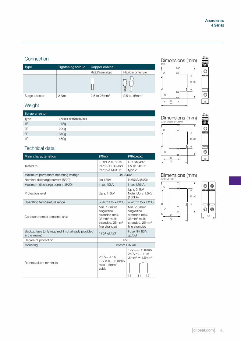
Weight
Surge arrestor
Type 970xxx or 970xxx/xxx
1P 115g
2P 220g
3P 340g4P 450g
Technical data
Main characteristics 970xxx 970xxx/xxx
Tested to E DIN VDE 0675 Part 6/11.89 and Part 6/A1/03.96
IEC 61643-1 EN 61643-11 type 2
Maximum permanent operating voltage Uc 340V~Nominal discharge current (8/20) isn 15kA In 60kA (8/20)Maximum discharge current (8/20) Imax 40kA Imax 120kA
Protection level Up ≤ 1.5kVUp ≤ 2.1kV Note: Up ≤ 1.5kV (100kA)
Operating temperature range -40°C to + 60°C -25°C to + 60°C
Conductor cross sectional area
Min. 1.5mm² single/fine stranded max. 35mm² multi stranded. 25mm² fine stranded
Min. 2.5mm² single/fine stranded max. 35mm² multi stranded. 25mm² fine stranded
Backup fuse (only required if not already provided in the mains) 125A gL/gG Fuse NH 63A
gL/gGDegree of protection IP20Mounting 35mm DIN rail
Remote alarm terminals
250V~ ≤ 1A12V d.c.~ ≤ 10mAmax 1.5mm² cable
12V ≥ 10mA250V ≤ 1A.5mm² 1.5mm²
Connection
Type Tightening torque Copper cables
Rigid/semi rigid Flexible or ferrule
Surge arrestor 2 Nm 2.5 to 25mm² 2.5 to 16mm²
Dimensions (mm)
Dimensions (mm)
Dimensions (mm)
970
970RM and 970RMT
970RM/120
18
15.4
18
15.4
36
80
7045
45
80
7045
45
80
7045
45
Accessories
Clipsal 4 Series Technical Specifications Catalogue62
4 Series
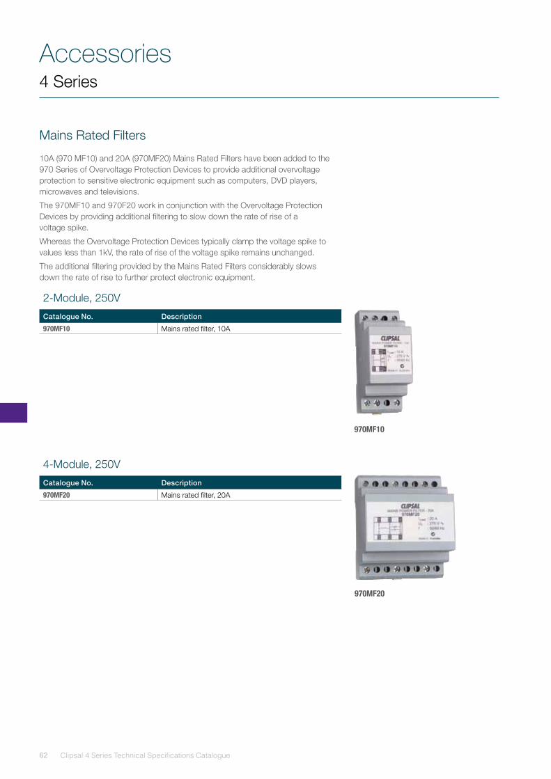
Mains Rated Filters
10A (970 MF10) and 20A (970MF20) Mains Rated Filters have been added to the 970 Series of Overvoltage Protection Devices to provide additional overvoltage protection to sensitive electronic equipment such as computers, DVD players, microwaves and televisions.
The 970MF10 and 970F20 work in conjunction with the Overvoltage Protection Devices by providing additional filtering to slow down the rate of rise of a voltage spike.
Whereas the Overvoltage Protection Devices typically clamp the voltage spike to values less than 1kV, the rate of rise of the voltage spike remains unchanged.
The additional filtering provided by the Mains Rated Filters considerably slows down the rate of rise to further protect electronic equipment.
970MF10
970MF20
2-Module, 250V
Catalogue No. Description
970MF10 Mains rated filter, 10A
4-Module, 250V
Catalogue No. Description
970MF20 Mains rated filter, 20A
63
Accessories4 Series
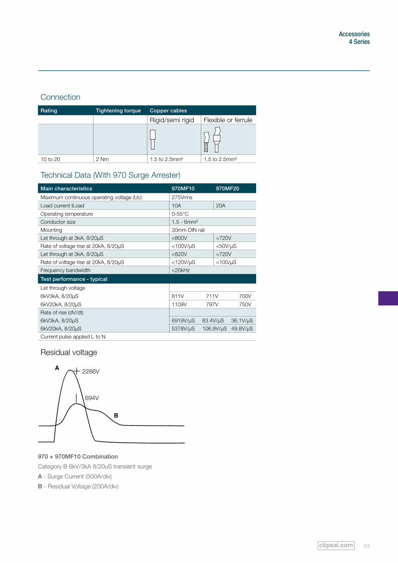
970 + 970MF10 Combination
Category B 6kV/3kA 8/20uS transient surge
A - Surge Current (500A/div)
B - Residual Voltage (200A/div)
Connection
Rating Tightening torque Copper cables
Rigid/semi rigid Flexible or ferrule
10 to 20 2 Nm 1.5 to 2.5mm² 1.5 to 2.5mm²
Residual voltage
Technical Data (With 970 Surge Arrester)
Main characteristics 970MF10 970MF20
Maximum continuous operating voltage (Uc) 275Vrms
Load current ILoad 10A 20A
Operating temperature 0-55°CConductor size 1.5 - 6mm²Mounting 30mm DIN railLet through at 3kA, 8/20µS <800V <720VRate of voltage rise at 20kA, 8/20µS <100V/µS <50V/µSLet through at 3kA, 8/20µS <820V <720VRate of voltage rise at 20kA, 8/20µS <120V/µS <100/µSFrequency bandwidth <20kHz
Test performance - typical
Let through voltage
6kV3kA, 8/20µS 811V 711V 700V
6kV20kA, 8/20µS 1109V 797V 750VRate of rise (dV/dt)6kV3kA, 8/20µS 6919V/µS 83.4V/µS 36.1V/µS6kV20kA, 8/20µS 5378V/µS 106.9V/µS 49.8V/µSCurrent pulse applied L to N
Accessories
Clipsal 4 Series Technical Specifications Catalogue64
4 Series
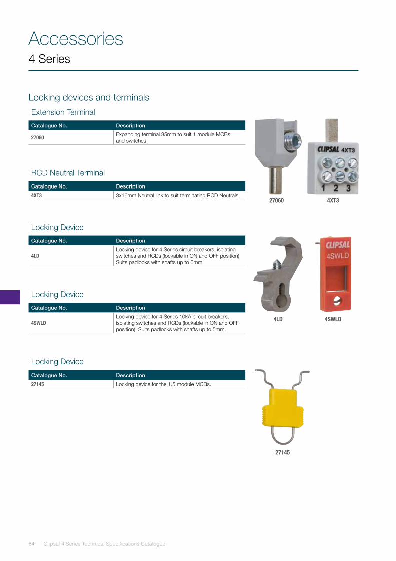
Locking devices and terminals
Extension Terminal
Catalogue No. Description
27060 Expanding terminal 35mm to suit 1 module MCBs and switches.
Locking Device
Catalogue No. Description
4SWLDLocking device for 4 Series 10kA circuit breakers, isolating switches and RCDs (lockable in ON and OFF position). Suits padlocks with shafts up to 5mm.
Locking Device
Catalogue No. Description
27145 Locking device for the 1.5 module MCBs.
Locking Device
Catalogue No. Description
4LDLocking device for 4 Series circuit breakers, isolating switches and RCDs (lockable in ON and OFF position). Suits padlocks with shafts up to 6mm.
RCD Neutral Terminal
Catalogue No. Description
4XT3 3x16mm Neutral link to suit terminating RCD Neutrals.27060
4LD
4XT3
27145
4SWLD
65
Accessories4 Series
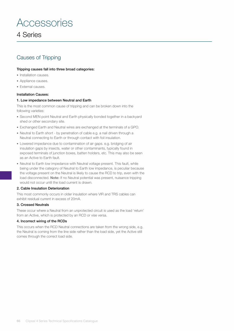
4F8
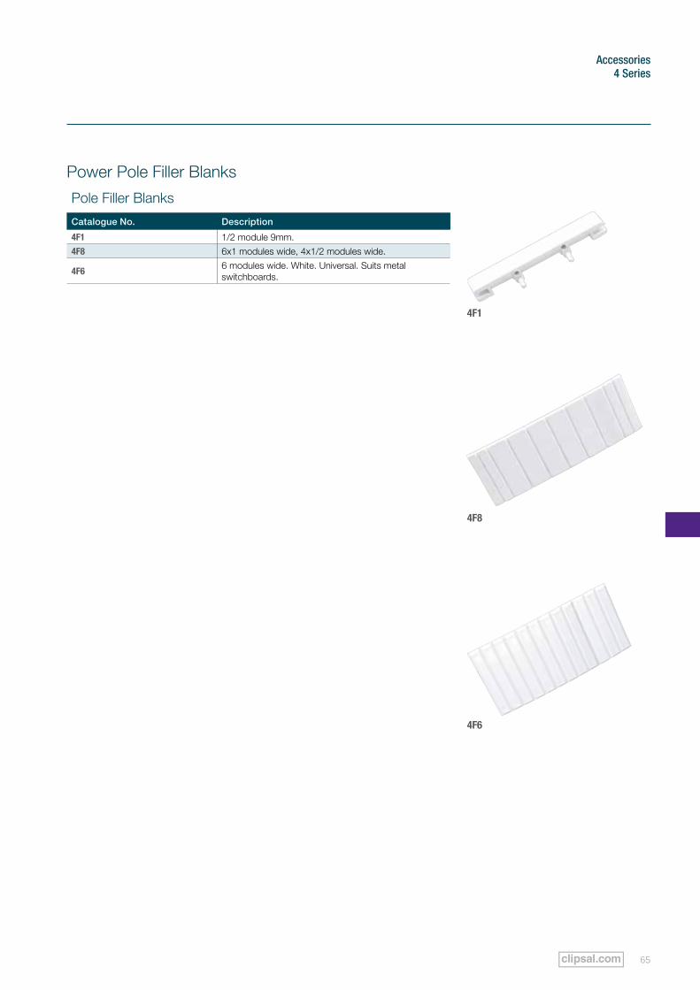
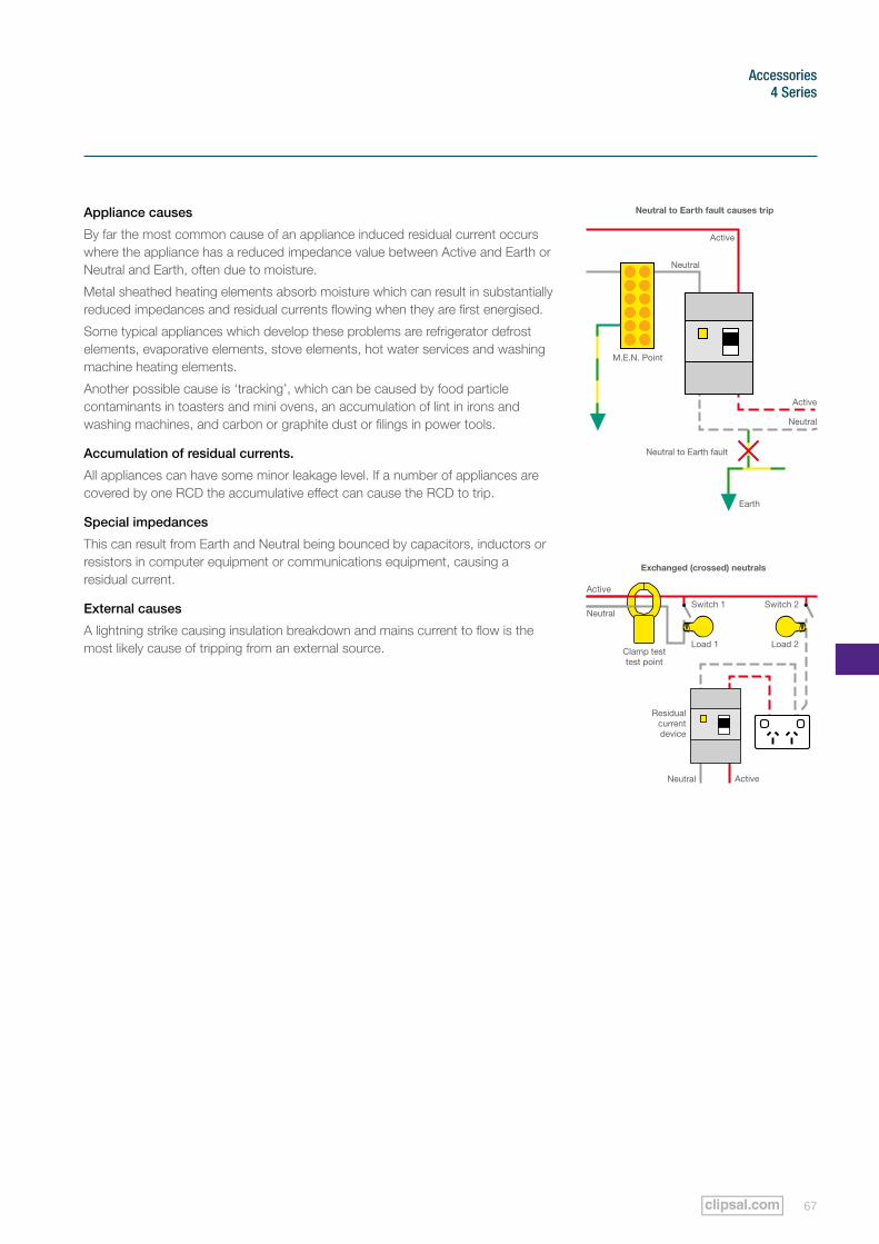
Power Pole Filler Blanks
Pole Filler Blanks
Catalogue No. Description
4F1 1/2 module 9mm.4F8 6x1 modules wide, 4x1/2 modules wide.
4F6 6 modules wide. White. Universal. Suits metal switchboards.
4F1
4F6
Accessories
Clipsal 4 Series Technical Specifications Catalogue66
4 Series
Causes of Tripping
Tripping causes fall into three broad categories:
• Installation causes.
• Appliance causes.
• External causes.
Installation Causes:
1. Low impedance between Neutral and Earth
This is the most common cause of tripping and can be broken down into the following varieties:
• Second MEN point Neutral and Earth physically bonded together in a backyard shed or other secondary site.
• Exchanged Earth and Neutral wires are exchanged at the terminals of a GPO.
• Neutral to Earth short - by penetration of cable e.g. a nail driven through a Neutral connecting to Earth or through contact with foil insulation.
• Lowered impedance due to contamination of air gaps. e.g. bridging of air insulation gaps by insects, water or other contaminants, typically found in exposed terminals of junction boxes, batten holders, etc. This may also be seen as an Active to Earth fault.
• Neutral to Earth low impedance with Neutral voltage present. This fault, while being under the category of Neutral to Earth low impedance, is peculiar because the voltage present on the Neutral is likely to cause the RCD to trip, even with the load disconnected. Note: If no Neutral potential was present, nuisance tripping would not occur until the load current is drawn.
2. Cable Insulation Deterioration
This most commonly occurs in older insulation where VIR and TRS cables can exhibit residual current in excess of 20mA.
3. Crossed Neutrals
These occur where a Neutral from an unprotected circuit is used as the load ‘return’ from an Active, which is protected by an RCD or vise versa.
4. Incorrect wiring of the RCDs
This occurs when the RCD Neutral connections are taken from the wrong side, e.g. the Neutral is coming from the line side rather than the load side, yet the Active still comes through the correct load side.
67
Accessories4 Series
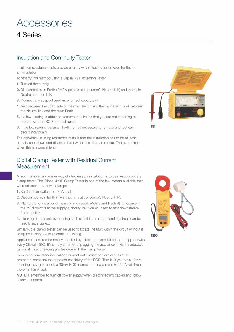
Appliance causes
By far the most common cause of an appliance induced residual current occurs where the appliance has a reduced impedance value between Active and Earth or Neutral and Earth, often due to moisture.
Metal sheathed heating elements absorb moisture which can result in substantially reduced impedances and residual currents flowing when they are first energised.
Some typical appliances which develop these problems are refrigerator defrost elements, evaporative elements, stove elements, hot water services and washing machine heating elements.
Another possible cause is ‘tracking’, which can be caused by food particle contaminants in toasters and mini ovens, an accumulation of lint in irons and washing machines, and carbon or graphite dust or filings in power tools.
Accumulation of residual currents.
All appliances can have some minor leakage level. If a number of appliances are covered by one RCD the accumulative effect can cause the RCD to trip.
Special impedances
This can result from Earth and Neutral being bounced by capacitors, inductors or resistors in computer equipment or communications equipment, causing a residual current.
External causes
A lightning strike causing insulation breakdown and mains current to flow is the most likely cause of tripping from an external source.
Active
Active
Earth
Neutral
Neutral
Neutral to Earth fault
Neutral to Earth fault causes trip
M.E.N. Point
Neutral
Neutral
Switch 1
Load 1Clamp test test point
Residual current device
Load 2
Switch 2
Active
Active
Exchanged (crossed) neutrals
Accessories
Clipsal 4 Series Technical Specifications Catalogue68
4 Series
Insulation and Continuity Tester
Insulation resistance tests provide a ready way of testing for leakage Earths in an installation.
To test by this method using a Clipsal 491 Insulation Tester:
1. Turn off the supply.
2. Disconnect main Earth (if MEN point is at consumer’s Neutral link) and the main Neutral from the link.
3. Connect any suspect appliance (or test separately).
4. Test between the Load side of the main switch and the main Earth, and between the Neutral link and the main Earth.
5. If a low reading is obtained, remove the circuits that you are not intending to protect with the RCD and test again.
6. If the low reading persists, it will then be necessary to remove and test each circuit individually.
The drawback in using resistance tests is that the installation has to be at least partially shut down and disassembled while tests are carried out. There are times when this is inconvenient.
Digital Clamp Tester with Residual Current Measurement
A much simpler and easier way of checking an installation is to use an appropriate clamp tester. The Clipsal 489D Clamp Tester is one of the few meters available that will read down to a few milliamps.
1. Set function switch to 40mA scale.
2. Disconnect main Earth (if MEN point is at consumer’s Neutral link).
3. Clamp the tongs around the incoming supply (Active and Neutral). Of course, if the MEN point is at the supply authority link, you will need to test downstream from that link.
4. If leakage is present, by opening each circuit in turn the offending circuit can be readily ascertained.
Similarly, the clamp tester can be used to locate the fault within the circuit without it being necessary to disassemble the wiring.
Appliances can also be readily checked by utilising the special adaptor supplied with every Clipsal 489D. It’s simply a matter of plugging the appliance in via the adaptor, turning it on and reading any leakage with the clamp tester.
Remember, any standing leakage current not eliminated from circuits to be protected increases the apparent sensitivity of the RCD. That is, if you have 10mA standing leakage current, a 30mA RCD (normal tripping current @ 25mA) will then trip on a 15mA fault.
NOTE: Remember to turn off power supply when disconnecting cables and follow safety standards.
491
489D
69
Accessories4 Series
RCD Tester with Digital Readout
Post installation testing is obviously vital and is definitely in the interests of good customer relations. Some statutory regulations require regular periods of checking and testing.
The objective is to test whether:
a) the RCD is actually providing protection on the required circuits
b) the RCD operates with a nominal residual current of 30mA flowing in the protected circuits
c) the test function of the RCD is operating.
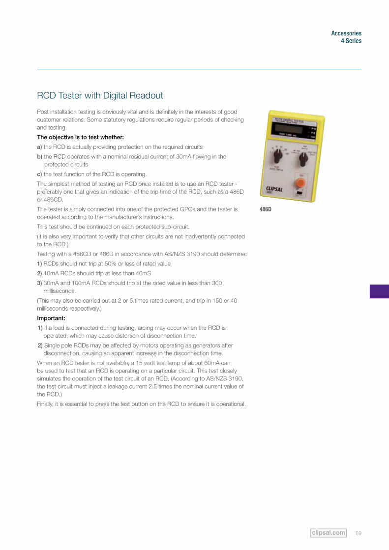
The simplest method of testing an RCD once installed is to use an RCD tester - preferably one that gives an indication of the trip time of the RCD, such as a 486D or 486CD.
The tester is simply connected into one of the protected GPOs and the tester is operated according to the manufacturer’s instructions.
This test should be continued on each protected sub-circuit.
(It is also very important to verify that other circuits are not inadvertently connected to the RCD.)
Testing with a 486CD or 486D in accordance with AS/NZS 3190 should determine:
1) RCDs should not trip at 50% or less of rated value
2) 10mA RCDs should trip at less than 40mS
3) 30mA and 100mA RCDs should trip at the rated value in less than 300 milliseconds.
(This may also be carried out at 2 or 5 times rated current, and trip in 150 or 40 milliseconds respectively.)
Important:
1) If a load is connected during testing, arcing may occur when the RCD is operated, which may cause distortion of disconnection time.
2) Single pole RCDs may be affected by motors operating as generators after disconnection, causing an apparent increase in the disconnection time.
When an RCD tester is not available, a 15 watt test lamp of about 60mA can be used to test that an RCD is operating on a particular circuit. This test closely simulates the operation of the test circuit of an RCD. (According to AS/NZS 3190, the test circuit must inject a leakage current 2.5 times the nominal current value of the RCD.)
Finally, it is essential to press the test button on the RCD to ensure it is operational.
486D
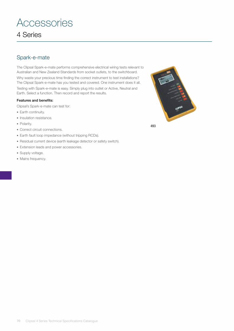
Accessories
Clipsal 4 Series Technical Specifications Catalogue70
Spark-e-mate
The Clipsal Spark-e-mate performs comprehensive electrical wiring tests relevant to Australian and New Zealand Standards from socket outlets, to the switchboard.
Why waste your precious time finding the correct instrument to test installations? The Clipsal Spark-e-mate has you tested and covered. One instrument does it all.
Testing with Spark-e-mate is easy. Simply plug into outlet or Active, Neutral and Earth. Select a function. Then record and report the results.
Features and benefits:
Clipsal’s Spark-e-mate can test for:
• Earth continuity.
• Insulation resistance.
• Polarity.
• Correct circuit connections.
• Earth fault loop impedance (without tripping RCDs).
• Residual current device (earth leakage detector or safety switch).
• Extension leads and power accessories.
• Supply voltage.
• Mains frequency.
493
4 Series
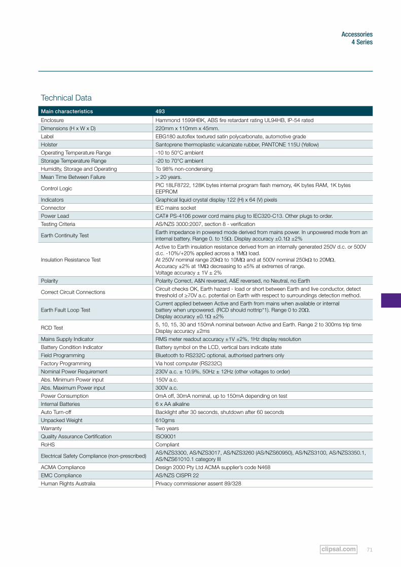
71
Accessories4 Series
Technical Data
Main characteristics 493
Enclosure Hammond 1599HBK, ABS fire retardant rating UL94HB, IP-54 ratedDimensions (H x W x D) 220mm x 110mm x 45mm.Label EBG180 autoflex textured satin polycarbonate, automotive gradeHolster Santoprene thermoplastic vulcanizate rubber, PANTONE 115U (Yellow)Operating Temperature Range -10 to 50°C ambientStorage Temperature Range -20 to 70°C ambientHumidity, Storage and Operating To 98% non-condensingMean Time Between Failure > 20 years.
Control Logic PIC 18LF8722, 128K bytes internal program flash memory, 4K bytes RAM, 1K bytes EEPROM
Indicators Graphical liquid crystal display 122 (H) x 64 (V) pixelsConnector IEC mains socketPower Lead CAT# PS-4106 power cord mains plug to IEC320-C13. Other plugs to order.Testing Criteria AS/NZS 3000:2007, section 8 - verification
Earth Continuity Test Earth impedance in powered mode derived from mains power. In unpowered mode from an internal battery. Range 0. to 15Ω. Display accuracy ±0.1Ω ±2%
Insulation Resistance Test
Active to Earth insulation resistance derived from an internally generated 250V d.c. or 500V d.c. -10%/+20% applied across a 1MΩ load.At 250V nominal range 20kΩ to 10MΩ and at 500V nominal 250kΩ to 20MΩ.Accuracy ±2% at 1MΩ decreasing to ±5% at extremes of range.Voltage accuracy ± 1V ± 2%
Polarity Polarity Correct, A&N reversed, A&E reversed, no Neutral, no Earth
Correct Circuit Connections Circuit checks OK, Earth hazard - load or short between Earth and live conductor, detect threshold of ≥70V a.c. potential on Earth with respect to surroundings detection method.
Earth Fault Loop TestCurrent applied between Active and Earth from mains when available or internalbattery when unpowered. (RCD should nottrip*1). Range 0 to 20Ω. Display accuracy ±0.1Ω ±2%
RCD Test 5, 10, 15, 30 and 150mA nominal between Active and Earth. Range 2 to 300ms trip time Display accuracy ±2ms
Mains Supply Indicator RMS meter readout accuracy ±1V ±2%, 1Hz display resolutionBattery Condition Indicator Battery symbol on the LCD, vertical bars indicate stateField Programming Bluetooth to RS232C optional, authorised partners onlyFactory Programming Via host computer (RS232C)Nominal Power Requirement 230V a.c. ± 10.9%, 50Hz ± 12Hz (other voltages to order)Abs. Minimum Power input 150V a.c.Abs. Maximum Power input 300V a.c.Power Consumption 0mA off, 30mA nominal, up to 150mA depending on testInternal Batteries 6 x AA alkalineAuto Turn-off Backlight after 30 seconds, shutdown after 60 secondsUnpacked Weight 610gmsWarranty Two yearsQuality Assurance Certification ISO9001RoHS Compliant
Electrical Safety Compliance (non-prescribed) AS/NZS3300, AS/NZS3017, AS/NZS3260 (AS/NZS60950), AS/NZS3100, AS/NZS3350.1, AS/NZS61010.1 category III
ACMA Compliance Design 2000 Pty Ltd ACMA supplier’s code N468EMC Compliance AS/NZS CISPR 22Human Rights Australia Privacy commissioner assent 89/328
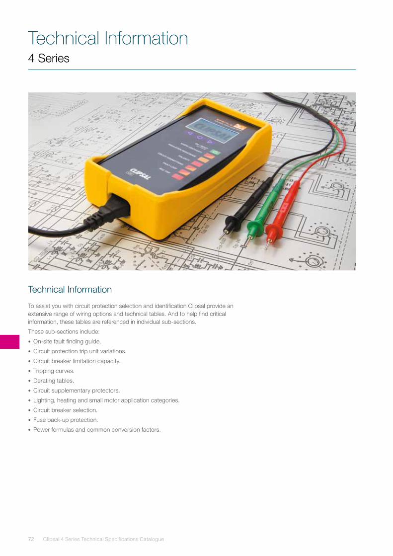
Clipsal 4 Series Technical Specifications Catalogue72
Technical Information4 Series
Technical Information
To assist you with circuit protection selection and identification Clipsal provide an extensive range of wiring options and technical tables. And to help find critical information, these tables are referenced in individual sub-sections.
These sub-sections include:
• On-site fault finding guide.
• Circuit protection trip unit variations.
• Circuit breaker limitation capacity.
• Tripping curves.
• Derating tables.
• Circuit supplementary protectors.
• Lighting, heating and small motor application categories.
• Circuit breaker selection.
• Fuse back-up protection.
• Power formulas and common conversion factors.
73
Technical information4 Series
Installation and wiring options
There are a number of types of RCDs that provide overall protection to an installation. The installing electrician needs to decide which type is best suited to individual installations as they arise.
The following wiring options are provided to assist installers in choosing the right type of RCD necessary for the installation.
Clipsal 4 Series Technical Specifications Catalogue74
Technical Information4 Series
Installation and Wiring Options (continued)
Option 1: Multiple GPO and lighting circuits protected by two-pole RCD
This is the most basic option and is the minimum configuration which allows compliance to AS/NZS 3000 Wiring Rules.The two-pole RCD offers greater flexibility, but you do need an extra Neutral link.
If you are installing the RCD in a Clipsal Moulded Switchboard Enclosure you will find that all the additional links are already provided.
The Neutrals from the circuits to be protected are relocated to this protected link and an appropriate size tail is taken from the main Neutral link through the RCD and back to the protected link.
On the Active side, the RCD is placed in circuit between the load side of the main switch and the line side of the fuses or circuit breakers controlling protected circuits.
This type of installation is suitable for use on new or existing installations.
But simply installing an RCD is often only part of the solution. The electrical contractor with the new rules must have a duty of care when making recommendations to a customer. And there’s a few things to consider before you can give the best advice.
For instance, a single RCD for everything in the house leaves the switch vulnerable to regular nuisance tripping, which means everything goes off at once - including the contents of the fridge. Not to mention the hazard of resetting the switch in the dark. Unsatisfied customers and annoying call-backs will almost certainly follow. An extension to the above circuit would be as follows:
• In retrofit installations, your choice of RCD may be partly determined by the physical size or available space on an existing switchboard panel, condition of existing wiring and existing protection devices such as fuses. In most cases the RCD can probably be fitted to the existing panel.
• In some instances, you may find it more convenient to remove old equipment and replace it with a compact, moulded switchboard to house all your new circuit protection devices.
• The customer may also like to take this opportunity of having a flush mounted moulded switchboard installed inside their facility. This provides your customer with the added benefits of security and convenience for re-setting devices in the event of circuit overloads or RCD tripping.
Benefits:
• Low cost.
• Easy installation.
• Allowance for additional circuits.
Disadvantages:
• A fault in any of the circuits will disconnect all including the lighting.
• Extra Neutral link is required.
• Accumulated leakage, meaning that all circuit leakages are added up and seen by one RCD.
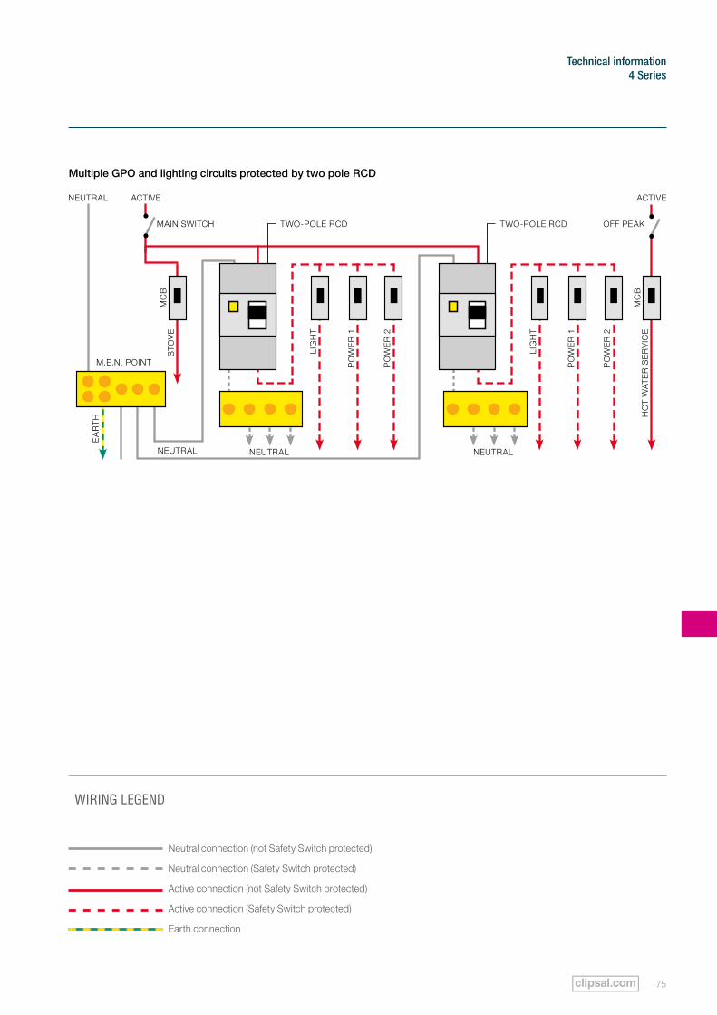
75
Technical information4 Series
TWO-POLE RCD TWO-POLE RCD
WIRING LEGEND
Neutral connection (not Safety Switch protected)
Neutral connection (Safety Switch protected)
Active connection (not Safety Switch protected)
Active connection (Safety Switch protected)
Earth connection
Multiple GPO and lighting circuits protected by two pole RCD
NEUTRAL ACTIVE
MAIN SWITCH OFF PEAk
MC
B
PO
WE
R 2
PO
WE
R 2
HO
T W
AT
ER
SE
RV
ICE
PO
WE
R 1
PO
WE
R 1
EA
RT
H
LIG
HT
LIG
HT
STO
VE
MC
B
NEUTRAL
M.E.N. POINT
ACTIVE
NEUTRAL NEUTRAL
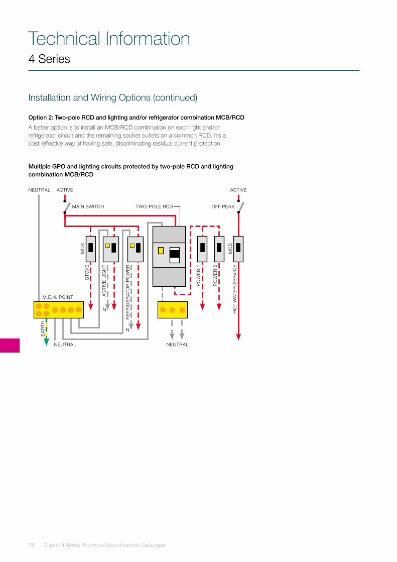
Clipsal 4 Series Technical Specifications Catalogue76
Technical Information4 Series
Installation and Wiring Options (continued)
Option 2: Two-pole RCD and lighting and/or refrigerator combination MCB/RCD
A better option is to install an MCB/RCD combination on each light and/or refrigerator circuit and the remaining socket outlets on a common RCD. It’s a cost-effective way of having safe, discriminating residual current protection.
Multiple GPO and lighting circuits protected by two-pole RCD and lighting combination MCB/RCD
NEUTRAL ACTIVE
MAIN SWITCH OFF PEAk
PO
WE
R 2
HO
T W
AT
ER
SE
RV
ICE
PO
WE
R 1
EA
RT
H
STO
VE
AC
TIV
E L
IGH
T
RE
FRIG
ER
ATO
R P
OW
ER
TWO-POLE RCD
NEUTRAL
N
N
NEUTRAL
M.E.N. POINT
ACTIVE
MC
B
MC
B
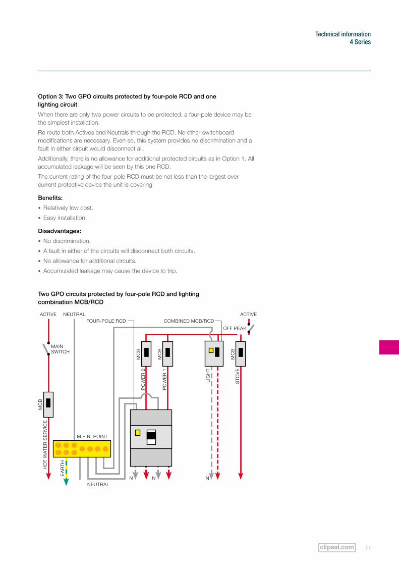
77
Technical information4 Series
Option 3: Two GPO circuits protected by four-pole RCD and one lighting circuit
When there are only two power circuits to be protected, a four-pole device may be the simplest installation.
Re route both Actives and Neutrals through the RCD. No other switchboard modifications are necessary. Even so, this system provides no discrimination and a fault in either circuit would disconnect all.
Additionally, there is no allowance for additional protected circuits as in Option 1. All accumulated leakage will be seen by this one RCD.
The current rating of the four-pole RCD must be not less than the largest over current protective device the unit is covering.
Benefits:
• Relatively low cost.
• Easy installation.
Disadvantages:
• No discrimination.
• A fault in either of the circuits will disconnect both circuits.
• No allowance for additional circuits.
• Accumulated leakage may cause the device to trip.
Two GPO circuits protected by four-pole RCD and lighting combination MCB/RCD
NEUTRAL ACTIVEACTIVE
MAIN SWITCH
OFF PEAk
HO
T W
AT
ER
SE
RV
ICE
PO
WE
R 1
PO
WE
R 2
EA
RT
H
STO
VE
LIG
HT
COMBINED MCB/RCDFOUR-POLE RCD
NN NNEUTRAL
M.E.N. POINT
MC
B
MC
B
MC
B
MC
B
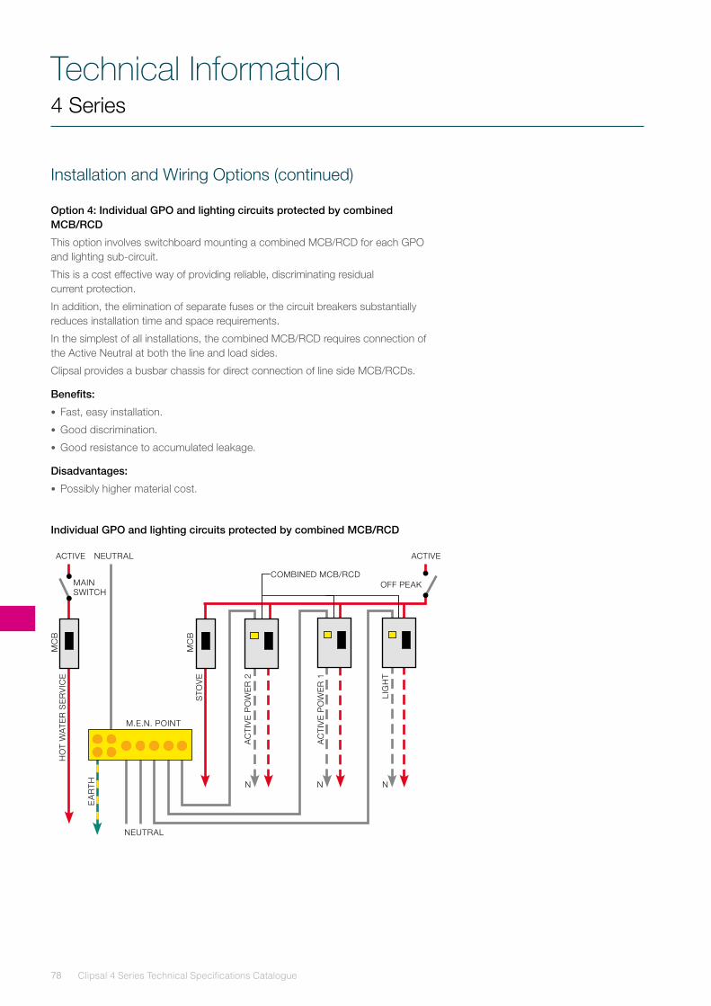
Clipsal 4 Series Technical Specifications Catalogue78
Technical Information
Installation and Wiring Options (continued)
Option 4: Individual GPO and lighting circuits protected by combined MCB/RCD
This option involves switchboard mounting a combined MCB/RCD for each GPO and lighting sub-circuit.
This is a cost effective way of providing reliable, discriminating residual current protection.
In addition, the elimination of separate fuses or the circuit breakers substantially reduces installation time and space requirements.
In the simplest of all installations, the combined MCB/RCD requires connection of the Active Neutral at both the line and load sides.
Clipsal provides a busbar chassis for direct connection of line side MCB/RCDs.
Benefits:
• Fast, easy installation.
• Good discrimination.
• Good resistance to accumulated leakage.
Disadvantages:
• Possibly higher material cost.
Individual GPO and lighting circuits protected by combined MCB/RCD
4 Series
NEUTRAL ACTIVEACTIVE
MAIN SWITCH
OFF PEAk
HO
T W
AT
ER
SE
RV
ICE
AC
TIV
E P
OW
ER
2
AC
TIV
E P
OW
ER
1
EA
RT
H
STO
VE
LIG
HT
COMBINED MCB/RCD
N N N
NEUTRAL
MC
B
MC
B
M.E.N. POINT
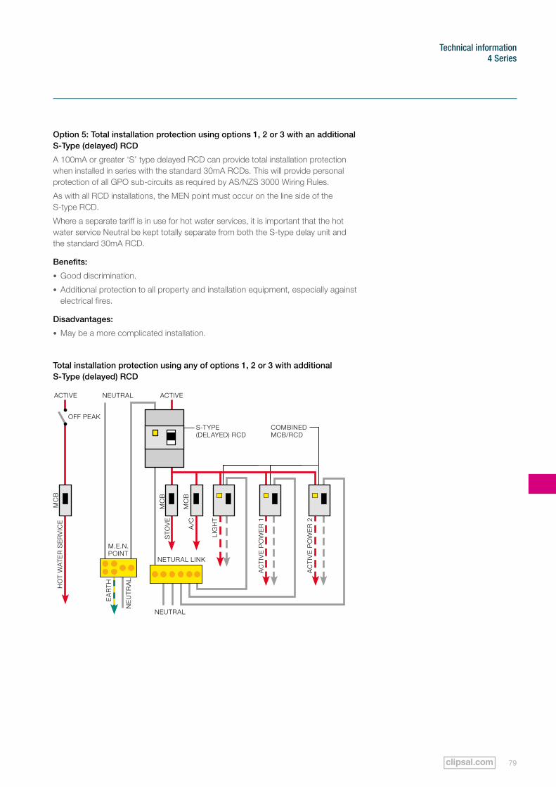
79
Technical information4 Series
Option 5: Total installation protection using options 1, 2 or 3 with an additional S-Type (delayed) RCD
A 100mA or greater ‘S’ type delayed RCD can provide total installation protection when installed in series with the standard 30mA RCDs. This will provide personal protection of all GPO sub-circuits as required by AS/NZS 3000 Wiring Rules.
As with all RCD installations, the MEN point must occur on the line side of the S-type RCD.
Where a separate tariff is in use for hot water services, it is important that the hot water service Neutral be kept totally separate from both the S-type delay unit and the standard 30mA RCD.
Benefits:
• Good discrimination.
• Additional protection to all property and installation equipment, especially against electrical fires.
Disadvantages:
• May be a more complicated installation.
Total installation protection using any of options 1, 2 or 3 with additional S-Type (delayed) RCD
S-TyPE (DELAyED) RCD
EA
RT
H
NEUTRAL ACTIVEACTIVE
HO
T W
AT
ER
SE
RV
ICE
AC
TIV
E P
OW
ER
2
AC
TIV
E P
OW
ER
1
STO
VE
A/C
LIG
HT
NEUTRAL
NE
UT
RA
L
M.E.N. POINT
NETURAL LINk
MC
B
MC
B
MC
B
COMBINED MCB/RCD
OFF PEAk
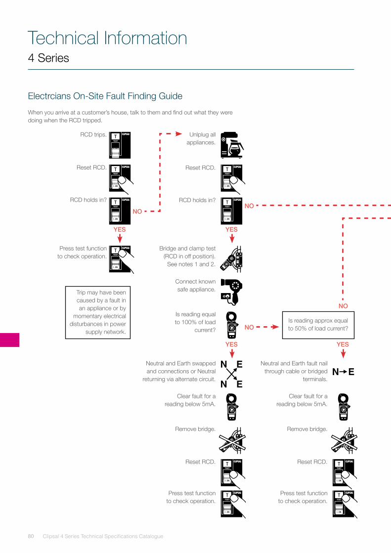
Clipsal 4 Series Technical Specifications Catalogue80
Technical Information4 Series
Electrcians On-Site Fault Finding Guide
When you arrive at a customer’s house, talk to them and find out what they were doing when the RCD tripped.
RCD trips.
Reset RCD.
RCD holds in?
Press test function to check operation.
Bridge and clamp test (RCD in off position).
See notes 1 and 2.
Neutral and Earth swapped and connections or Neutral
returning via alternate circuit.
Neutral and Earth fault nail through cable or bridged
terminals.
Is reading approx equal to 50% of load current?
Reset RCD. Reset RCD.
Press test function to check operation.
Press test function to check operation.
Connect known safe appliance.Trip may have been
caused by a fault in an appliance or by
momentary electrical disturbances in power
supply network.
Clear fault for a reading below 5mA.
Clear fault for a reading below 5mA.
Is reading equal to 100% of load
current?
Remove bridge. Remove bridge.
Unlplug all appliances.
Reset RCD.
RCD holds in?
NONO
NO
NO
YES YES
YES YES
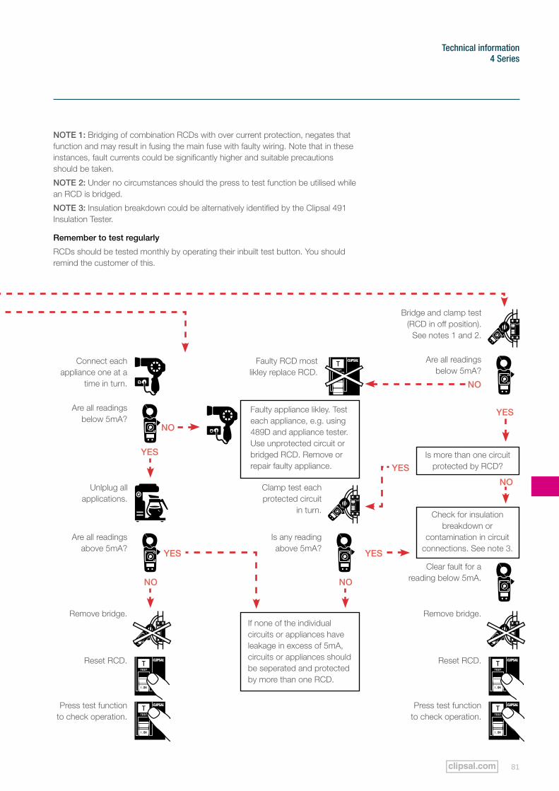
81
Technical information4 Series
Bridge and clamp test (RCD in off position).
See notes 1 and 2.
Is more than one circuit protected by RCD?
Check for insulation breakdown or
contamination in circuit connections. See note 3.
If none of the individual circuits or appliances have leakage in excess of 5mA, circuits or appliances should be seperated and protected by more than one RCD.
Reset RCD.Reset RCD.
Press test function to check operation.
Press test function to check operation.
Connect each appliance one at a
time in turn.
Faulty appliance likley. Test each appliance, e.g. using 489D and appliance tester. Use unprotected circuit or bridged RCD. Remove or repair faulty appliance.
Clear fault for a reading below 5mA.
Are all readings below 5mA?
Are all readings below 5mA?
Faulty RCD most likley replace RCD.
Are all readings above 5mA?
Is any reading above 5mA?
Remove bridge.Remove bridge.
Clamp test each protected circuit
in turn.
Unlplug all applications.
NOTE 1: Bridging of combination RCDs with over current protection, negates that function and may result in fusing the main fuse with faulty wiring. Note that in these instances, fault currents could be significantly higher and suitable precautions should be taken.
NOTE 2: Under no circumstances should the press to test function be utilised while an RCD is bridged.
NOTE 3: Insulation breakdown could be alternatively identified by the Clipsal 491 Insulation Tester.
Remember to test regularly
RCDs should be tested monthly by operating their inbuilt test button. you should remind the customer of this.
NO
NO
YES
YESYES
YES
YES
NO
NO NO
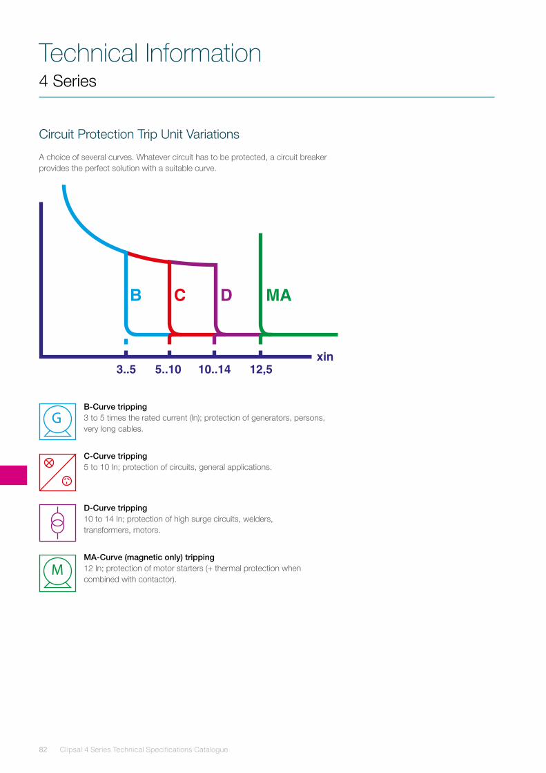
Clipsal 4 Series Technical Specifications Catalogue82
Technical Information4 Series
Circuit Protection Trip Unit Variations
A choice of several curves. Whatever circuit has to be protected, a circuit breaker provides the perfect solution with a suitable curve.
B-Curve tripping 3 to 5 times the rated current (ln); protection of generators, persons, very long cables.
C-Curve tripping 5 to 10 In; protection of circuits, general applications.
D-Curve tripping 10 to 14 In; protection of high surge circuits, welders, transformers, motors.
MA-Curve (magnetic only) tripping 12 In; protection of motor starters (+ thermal protection when combined with contactor).
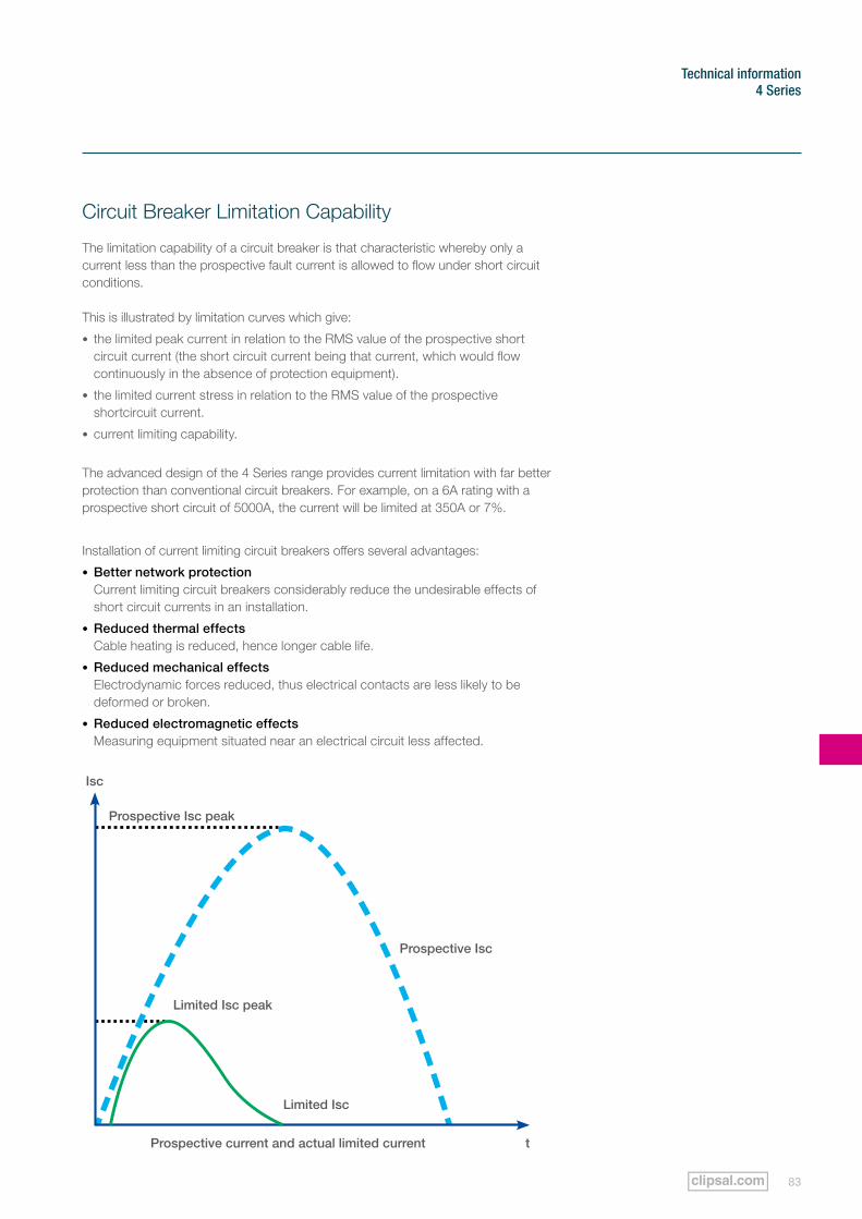
83
Technical information4 Series
Circuit Breaker Limitation Capability
The limitation capability of a circuit breaker is that characteristic whereby only a current less than the prospective fault current is allowed to flow under short circuit conditions. This is illustrated by limitation curves which give:
• the limited peak current in relation to the RMS value of the prospective short circuit current (the short circuit current being that current, which would flow continuously in the absence of protection equipment).
• the limited current stress in relation to the RMS value of the prospective shortcircuit current.
• current limiting capability.
The advanced design of the 4 Series range provides current limitation with far better protection than conventional circuit breakers. For example, on a 6A rating with a prospective short circuit of 5000A, the current will be limited at 350A or 7%.
Installation of current limiting circuit breakers offers several advantages:
• Better network protection Current limiting circuit breakers considerably reduce the undesirable effects of short circuit currents in an installation.
• Reduced thermal effects Cable heating is reduced, hence longer cable life.
• Reduced mechanical effects Electrodynamic forces reduced, thus electrical contacts are less likely to be deformed or broken.
• Reduced electromagnetic effects Measuring equipment situated near an electrical circuit less affected.
Isc
Prospective Isc
Prospective current and actual limited current t
Limited Isc peak
Limited Isc
Prospective Isc peak
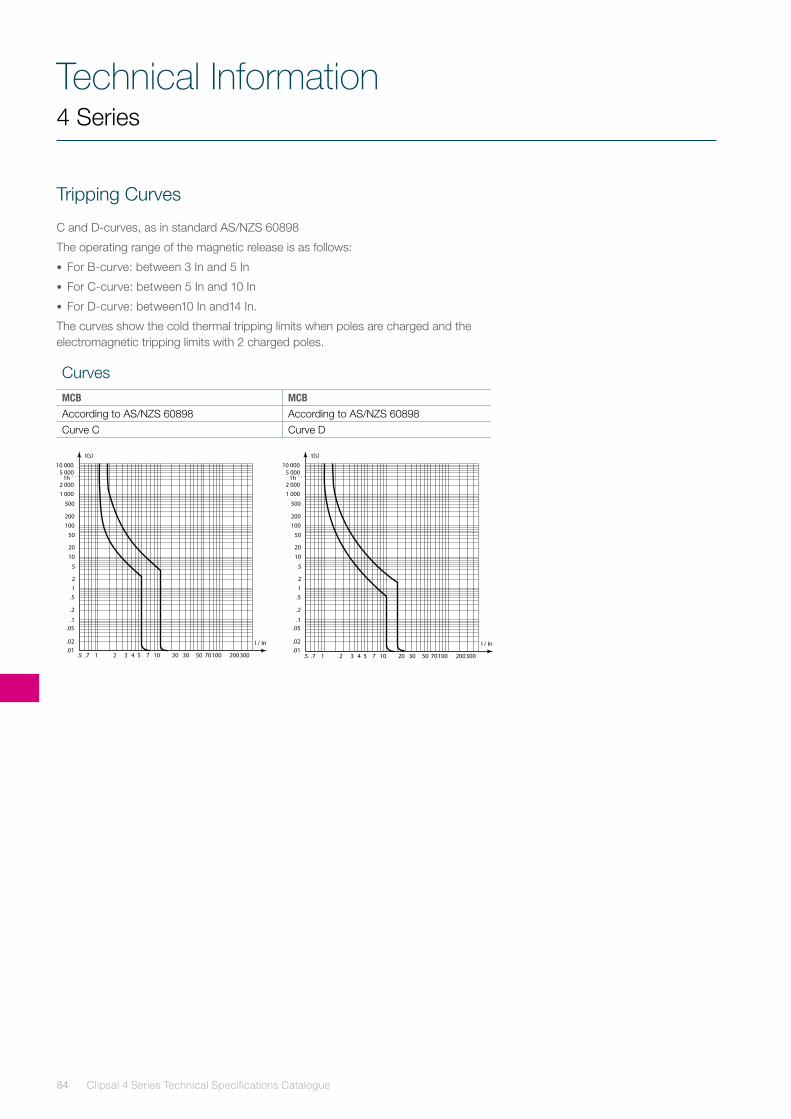
Clipsal 4 Series Technical Specifications Catalogue84
Technical Information4 Series
Tripping Curves
C and D-curves, as in standard AS/NZS 60898
The operating range of the magnetic release is as follows:
• For B-curve: between 3 In and 5 In
• For C-curve: between 5 In and 10 In
• For D-curve: between10 In and14 In.
The curves show the cold thermal tripping limits when poles are charged and the electromagnetic tripping limits with 2 charged poles.
CurvesMCB MCB
According to AS/NZS 60898 According to AS/NZS 60898Curve C Curve D
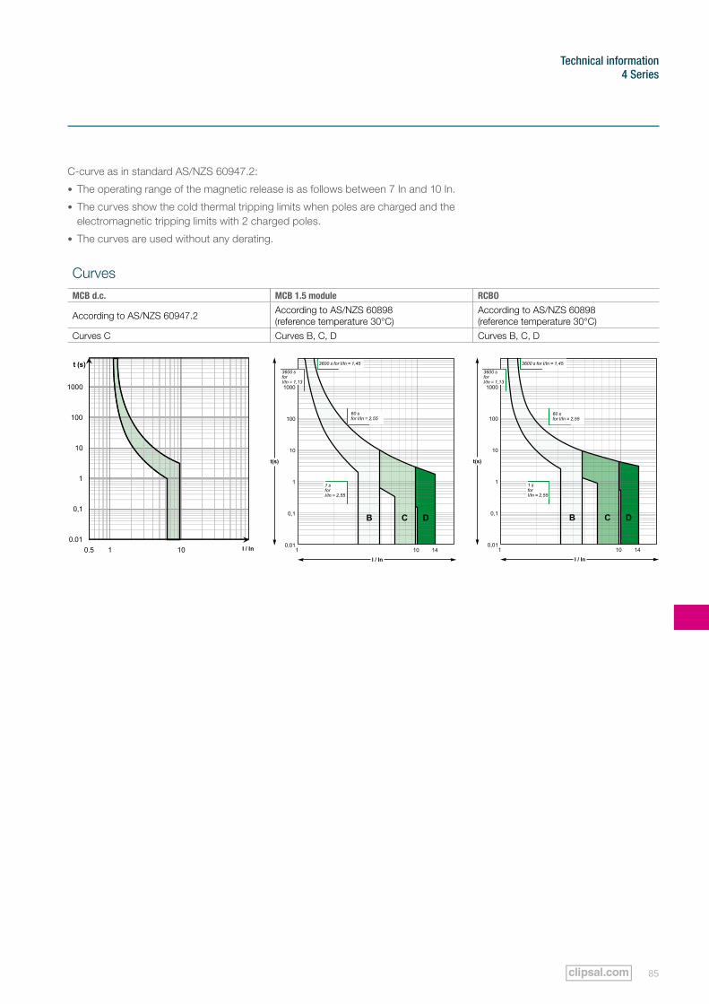
85
Technical information4 Series
C-curve as in standard AS/NZS 60947.2:
• The operating range of the magnetic release is as follows between 7 In and 10 In.
• The curves show the cold thermal tripping limits when poles are charged and the electromagnetic tripping limits with 2 charged poles.
• The curves are used without any derating.
CurvesMCB d.c. MCB 1.5 module RCBO
According to AS/NZS 60947.2 According to AS/NZS 60898 (reference temperature 30°C)
According to AS/NZS 60898 (reference temperature 30°C)
Curves C Curves B, C, D Curves B, C, D
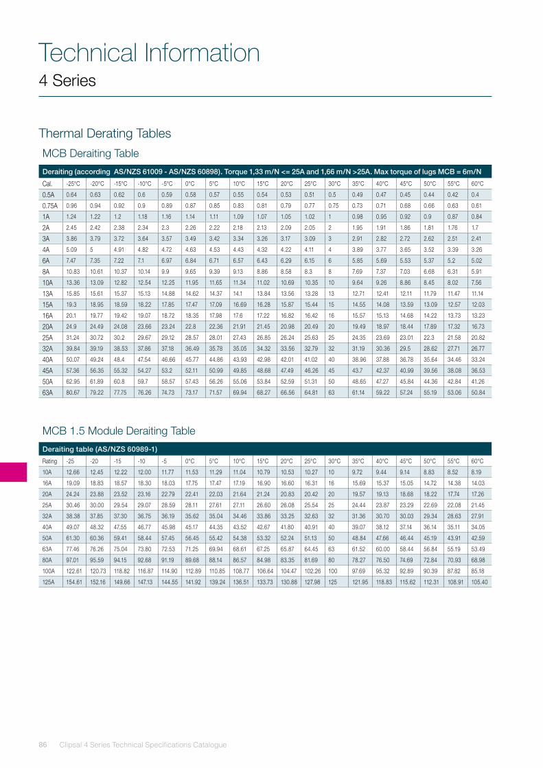
Clipsal 4 Series Technical Specifications Catalogue86
Technical Information
MCB Deraiting Table
Deraiting (according AS/NZS 61009 - AS/NZS 60898). Torque 1,33 m/N <= 25A and 1,66 m/N >25A. Max torque of lugs MCB = 6m/N
Cal. -25°C -20°C -15°C -10°C -5°C 0°C 5°C 10°C 15°C 20°C 25°C 30°C 35°C 40°C 45°C 50°C 55°C 60°C
0.5A 0.64 0.63 0.62 0.6 0.59 0.58 0.57 0.55 0.54 0.53 0.51 0.5 0.49 0.47 0.45 0.44 0.42 0.4
0.75A 0.96 0.94 0.92 0.9 0.89 0.87 0.85 0.83 0.81 0.79 0.77 0.75 0.73 0.71 0.68 0.66 0.63 0.61
1A 1.24 1.22 1.2 1.18 1.16 1.14 1.11 1.09 1.07 1.05 1.02 1 0.98 0.95 0.92 0.9 0.87 0.84
2A 2.45 2.42 2.38 2.34 2.3 2.26 2.22 2.18 2.13 2.09 2.05 2 1.95 1.91 1.86 1.81 1.76 1.7
3A 3.86 3.79 3.72 3.64 3.57 3.49 3.42 3.34 3.26 3.17 3.09 3 2.91 2.82 2.72 2.62 2.51 2.41
4A 5.09 5 4.91 4.82 4.72 4.63 4.53 4.43 4.32 4.22 4.11 4 3.89 3.77 3.65 3.52 3.39 3.26
6A 7.47 7.35 7.22 7.1 6.97 6.84 6.71 6.57 6.43 6.29 6.15 6 5.85 5.69 5.53 5.37 5.2 5.02
8A 10.83 10.61 10.37 10.14 9.9 9.65 9.39 9.13 8.86 8.58 8.3 8 7.69 7.37 7.03 6.68 6.31 5.91
10A 13.36 13.09 12.82 12.54 12.25 11.95 11.65 11.34 11.02 10.69 10.35 10 9.64 9.26 8.86 8.45 8.02 7.56
13A 15.85 15.61 15.37 15.13 14.88 14.62 14.37 14.1 13.84 13.56 13.28 13 12.71 12.41 12.11 11.79 11.47 11.14
15A 19.3 18.95 18.59 18.22 17.85 17.47 17.09 16.69 16.28 15.87 15.44 15 14.55 14.08 13.59 13.09 12.57 12.03
16A 20.1 19.77 19.42 19.07 18.72 18.35 17.98 17.6 17.22 16.82 16.42 16 15.57 15.13 14.68 14.22 13.73 13.23
20A 24.9 24.49 24.08 23.66 23.24 22.8 22.36 21.91 21.45 20.98 20.49 20 19.49 18.97 18.44 17.89 17.32 16.73
25A 31.24 30.72 30.2 29.67 29.12 28.57 28.01 27.43 26.85 26.24 25.63 25 24.35 23.69 23.01 22.3 21.58 20.82
32A 39.84 39.19 38.53 37.86 37.18 36.49 35.78 35.05 34.32 33.56 32.79 32 31.19 30.36 29.5 28.62 27.71 26.77
40A 50.07 49.24 48.4 47.54 46.66 45.77 44.86 43.93 42.98 42.01 41.02 40 38.96 37.88 36.78 35.64 34.46 33.24
45A 57.36 56.35 55.32 54.27 53.2 52.11 50.99 49.85 48.68 47.49 46.26 45 43.7 42.37 40.99 39.56 38.08 36.53
50A 62.95 61.89 60.8 59.7 58.57 57.43 56.26 55.06 53.84 52.59 51.31 50 48.65 47.27 45.84 44.36 42.84 41.26
63A 80.67 79.22 77.75 76.26 74.73 73.17 71.57 69.94 68.27 66.56 64.81 63 61.14 59.22 57.24 55.19 53.06 50.84
4 Series
Thermal Derating Tables
MCB 1.5 Module Deraiting Table
Deraiting table (AS/NZS 60989-1)
Rating -25 -20 -15 -10 -5 0°C 5°C 10°C 15°C 20°C 25°C 30°C 35°C 40°C 45°C 50°C 55°C 60°C
10A 12.66 12.45 12.22 12.00 11.77 11.53 11.29 11.04 10.79 10.53 10.27 10 9.72 9.44 9.14 8.83 8.52 8.19
16A 19.09 18.83 18.57 18.30 18.03 17.75 17.47 17.19 16.90 16.60 16.31 16 15.69 15.37 15.05 14.72 14.38 14.03
20A 24.24 23.88 23.52 23.16 22.79 22.41 22.03 21.64 21.24 20.83 20.42 20 19.57 19.13 18.68 18.22 17.74 17.26
25A 30.46 30.00 29.54 29.07 28.59 28.11 27.61 27.11 26.60 26.08 25.54 25 24.44 23.87 23.29 22.69 22.08 21.45
32A 38.38 37.85 37.30 36.75 36.19 35.62 35.04 34.46 33.86 33.25 32.63 32 31.36 30.70 30.03 29.34 28.63 27.91
40A 49.07 48.32 47.55 46.77 45.98 45.17 44.35 43.52 42.67 41.80 40.91 40 39.07 38.12 37.14 36.14 35.11 34.05
50A 61.30 60.36 59.41 58.44 57.45 56.45 55.42 54.38 53.32 52.24 51.13 50 48.84 47.66 46.44 45.19 43.91 42.59
63A 77.46 76.26 75.04 73.80 72.53 71.25 69.94 68.61 67.25 65.87 64.45 63 61.52 60.00 58.44 56.84 55.19 53.49
80A 97.01 95.59 94.15 92.68 91.19 89.68 88.14 86.57 84.98 83.35 81.69 80 78.27 76.50 74.69 72.84 70.93 68.98
100A 122.61 120.73 118.82 116.87 114.90 112.89 110.85 108.77 106.64 104.47 102.26 100 97.69 95.32 92.89 90.39 87.82 85.18
125A 154.61 152.16 149.66 147.13 144.55 141.92 139.24 136.51 133.73 130.88 127.98 125 121.95 118.83 115.62 112.31 108.91 105.40
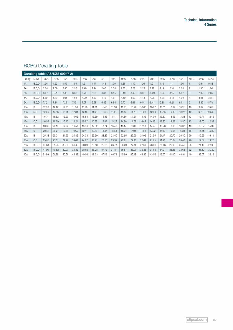
87
Technical information4 Series
RCBO Deraiting Table
Deraiting table (AS/NZS 60947-2)
Rating Curve -25°C -20°C -15°C -10°C -5°C 0°C 5°C 10°C 15°C 20°C 25°C 30°C 35°C 40°C 45°C 50°C 55°C 60°C
1A B,C,D 1.66 1.62 1.59 1.55 1.51 1.47 1.43 1.39 1.35 1.30 1.26 1.21 1.16 1.11 1.06 1 0.94 0.88
2A B,C,D 2.64 2.60 2.56 2.52 2.48 2.44 2.40 2.36 2.32 2.28 2.23 2.19 2.14 2.10 2.05 2 1.95 1.90
3A B,C,D 3.97 3.91 3.86 3.80 3.74 3.68 3.61 3.55 3.49 3.42 3.36 3.29 3.22 3.15 3.07 3 2.92 2.85
4A B,C,D 5.19 5.12 5.05 4.98 4.90 4.83 4.75 4.67 4.60 4.52 4.43 4.35 4.27 4.18 4.09 4 3.91 3.81
6A B,C,D 7.42 7.34 7.25 7.16 7.07 6.98 6.89 6.80 6.70 6.61 6.51 6.41 6.31 6.21 6.11 6 5.89 5.78
10A B 12.33 12.19 12.05 11.90 11.76 11.61 11.46 11.30 11.15 10.99 10.83 10.67 10.51 10.34 10.17 10 9.82 9.65
10A C,D 12.85 12.68 12.51 12.34 12.16 11.98 11.80 11.61 11.42 11.23 11.03 10.84 10.63 10.43 10.22 10 9.78 9.56
13A B 16.74 16.52 16.29 16.06 15.83 15.59 15.35 15.11 14.86 14.61 14.36 14.09 13.83 13.56 13.28 13 12.71 12.42
13A C,D 16.92 16.69 16.45 16.21 15.97 15.72 15.47 15.22 14.96 14.69 14.43 14.15 13.87 13.59 13.30 13 12.70 12.38
16A B,C 20.36 20.10 19.84 19.57 19.30 19.02 18.74 18.46 18.17 17.87 17.58 17.27 16.96 16.65 16.33 16 15.67 15.32
16A D 20.51 20.24 19.97 19.69 19.41 19.13 18.84 18.54 18.24 17.94 17.63 17.32 17.00 16.67 16.34 16 15.65 15.30
20A B 25.33 25.01 24.69 24.36 24.03 23.69 23.35 23.00 22.65 22.29 21.92 21.55 21.17 20.79 20.40 20 19.59 19.18
20A C,D 25.65 25.31 24.97 24.62 24.27 23.91 23.55 23.18 22.81 22.43 22.04 21.65 21.25 20.84 20.42 20 19.57 19.12
25A B,C,D 31.63 31.23 30.83 30.42 30.00 29.58 29.16 28.72 28.29 27.84 27.39 26.93 26.46 25.98 25.50 25 24.49 23.98
32A B,C,D 41.06 40.52 39.97 39.42 38.85 38.28 37.70 37.11 36.51 35.90 35.28 34.65 34.01 33.35 32.68 32 31.30 30.59
40A B,C,D 51.99 51.28 50.56 49.83 49.08 48.33 47.56 46.78 45.99 45.18 44.36 43.52 42.67 41.80 40.91 40 39.07 38.12
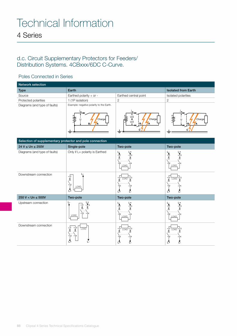
Clipsal 4 Series Technical Specifications Catalogue88
Technical Information
Selection of supplementary protector and pole connection
24 V ≤ Un ≤ 250V Single-pole Two-pole Two-pole
Diagrams (and type of faults) Only if L+ polarity is Earthed
Downstream connection
250 V < Un ≤ 500V Two-pole Two-pole Two-pole
Upstream connection
Downstream connection
4 Series
d.c. Circuit Supplementary Protectors for Feeders/Distribution Systems. 4CBxxx/6DC C-Curve.
Poles Connected in Series
Network selection
Type Earth Isolated from Earth
Source Earthed polarity + or - Earthed central point Isolated polaritiesProtected polarities 1 (1P isolation) 2 2Diagrams (and type of faults) Example: negative polarity to the Earth.
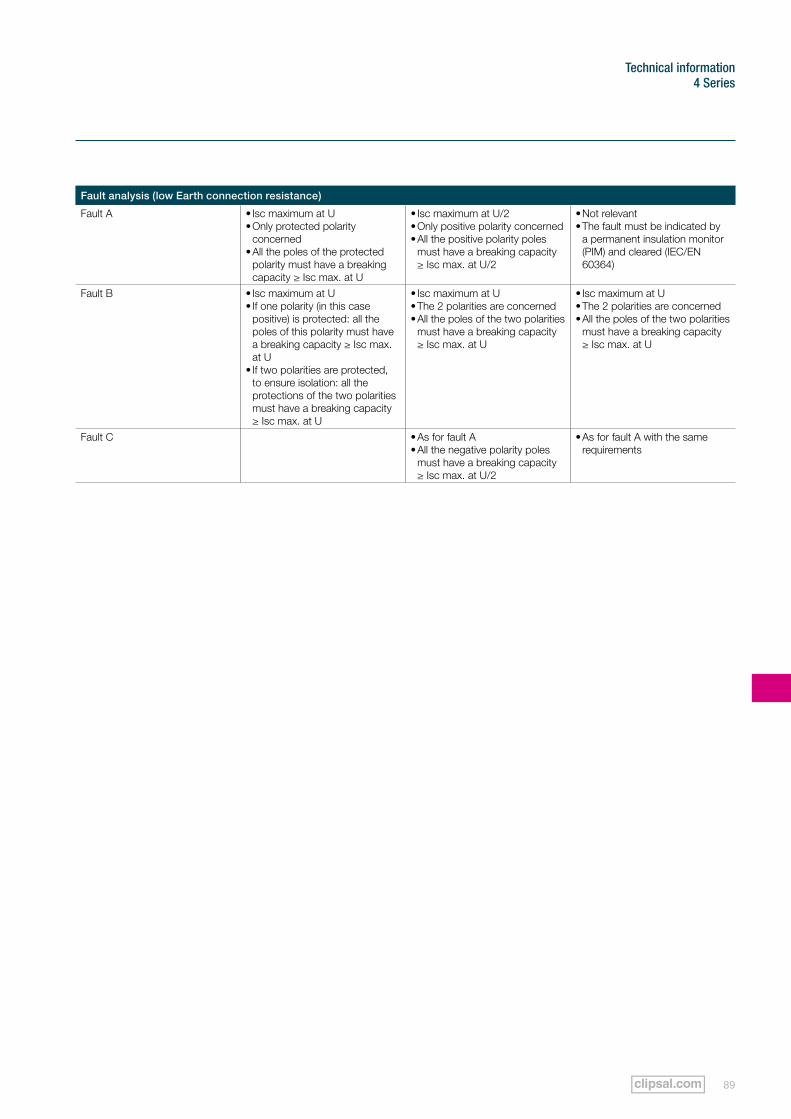
89
Technical information4 Series
Fault analysis (low Earth connection resistance)
Fault A • Isc maximum at U• Only protected polarity
concerned • All the poles of the protected
polarity must have a breaking capacity ≥ Isc max. at U
• Isc maximum at U/2• Only positive polarity concerned• All the positive polarity poles
must have a breaking capacity ≥ Isc max. at U/2
• Not relevant• The fault must be indicated by
a permanent insulation monitor (PIM) and cleared (IEC/EN 60364)
Fault B • Isc maximum at U• If one polarity (in this case
positive) is protected: all the poles of this polarity must have a breaking capacity ≥ Isc max. at U
• If two polarities are protected, to ensure isolation: all the protections of the two polarities must have a breaking capacity ≥ Isc max. at U
• Isc maximum at U• The 2 polarities are concerned• All the poles of the two polarities
must have a breaking capacity ≥ Isc max. at U
• Isc maximum at U• The 2 polarities are concerned• All the poles of the two polarities
must have a breaking capacity ≥ Isc max. at U
Fault C • As for fault A• All the negative polarity poles
must have a breaking capacity ≥ Isc max. at U/2
• As for fault A with the same requirements
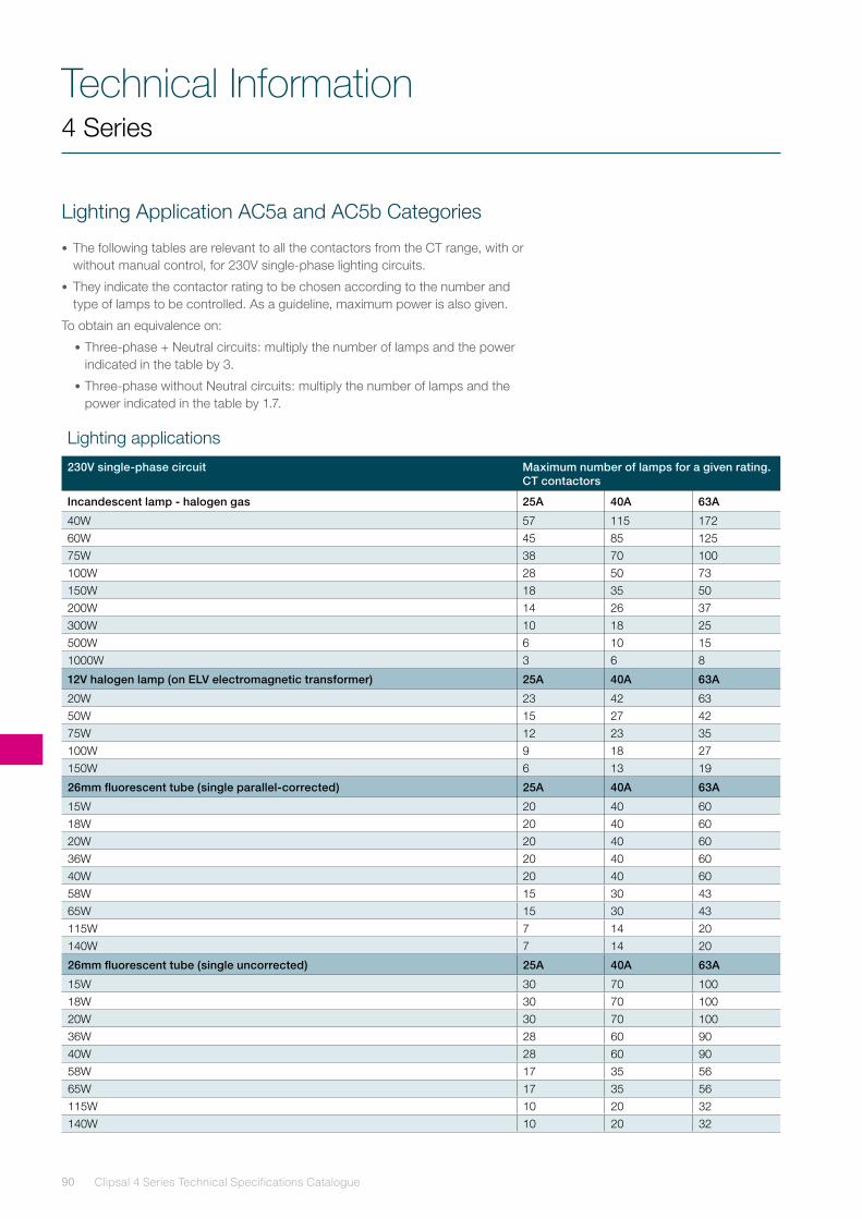
Clipsal 4 Series Technical Specifications Catalogue90
Technical Information4 Series
Lighting Application AC5a and AC5b Categories
• The following tables are relevant to all the contactors from the CT range, with or without manual control, for 230V single-phase lighting circuits.
• They indicate the contactor rating to be chosen according to the number and type of lamps to be controlled. As a guideline, maximum power is also given.
To obtain an equivalence on:
•Three-phase + Neutral circuits: multiply the number of lamps and the power indicated in the table by 3.
•Three-phase without Neutral circuits: multiply the number of lamps and the power indicated in the table by 1.7.
Lighting applications
230V single-phase circuit Maximum number of lamps for a given rating. CT contactors
Incandescent lamp - halogen gas 25A 40A 63A
40W 57 115 17260W 45 85 12575W 38 70 100100W 28 50 73150W 18 35 50200W 14 26 37300W 10 18 25500W 6 10 151000W 3 6 8
12V halogen lamp (on ELV electromagnetic transformer) 25A 40A 63A
20W 23 42 6350W 15 27 4275W 12 23 35100W 9 18 27150W 6 13 19
26mm fluorescent tube (single parallel-corrected) 25A 40A 63A
15W 20 40 6018W 20 40 6020W 20 40 6036W 20 40 6040W 20 40 6058W 15 30 4365W 15 30 43115W 7 14 20140W 7 14 20
26mm fluorescent tube (single uncorrected) 25A 40A 63A
15W 30 70 10018W 30 70 10020W 30 70 10036W 28 60 9040W 28 60 9058W 17 35 5665W 17 35 56115W 10 20 32140W 10 20 32
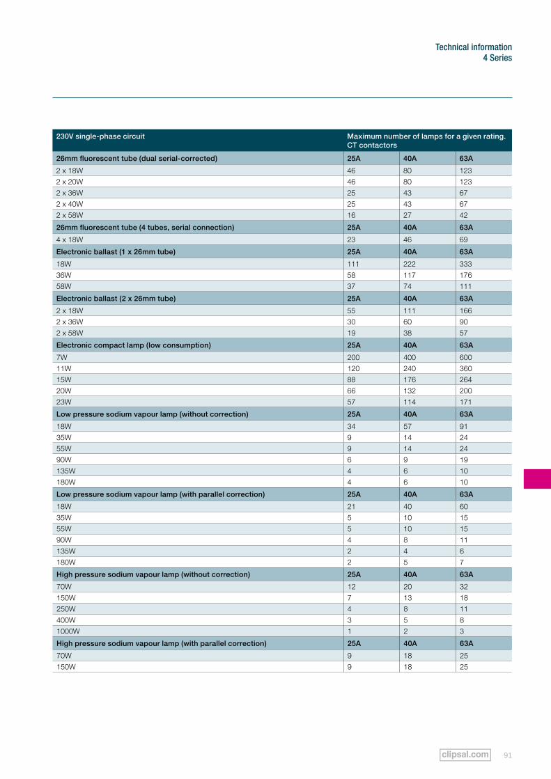
91
Technical information4 Series
230V single-phase circuit Maximum number of lamps for a given rating. CT contactors
26mm fluorescent tube (dual serial-corrected) 25A 40A 63A
2 x 18W 46 80 1232 x 20W 46 80 1232 x 36W 25 43 672 x 40W 25 43 672 x 58W 16 27 42
26mm fluorescent tube (4 tubes, serial connection) 25A 40A 63A
4 x 18W 23 46 69
Electronic ballast (1 x 26mm tube) 25A 40A 63A
18W 111 222 33336W 58 117 17658W 37 74 111
Electronic ballast (2 x 26mm tube) 25A 40A 63A
2 x 18W 55 111 1662 x 36W 30 60 902 x 58W 19 38 57
Electronic compact lamp (low consumption) 25A 40A 63A
7W 200 400 60011W 120 240 36015W 88 176 26420W 66 132 20023W 57 114 171
Low pressure sodium vapour lamp (without correction) 25A 40A 63A
18W 34 57 9135W 9 14 2455W 9 14 2490W 6 9 19135W 4 6 10180W 4 6 10
Low pressure sodium vapour lamp (with parallel correction) 25A 40A 63A
18W 21 40 6035W 5 10 1555W 5 10 1590W 4 8 11135W 2 4 6180W 2 5 7
High pressure sodium vapour lamp (without correction) 25A 40A 63A
70W 12 20 32150W 7 13 18250W 4 8 11400W 3 5 81000W 1 2 3
High pressure sodium vapour lamp (with parallel correction) 25A 40A 63A
70W 9 18 25150W 9 18 25
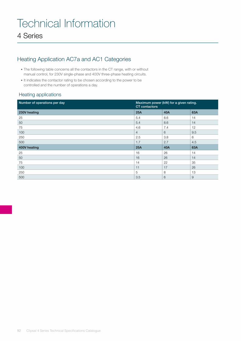
Clipsal 4 Series Technical Specifications Catalogue92
Technical Information4 Series
Heating Application AC7a and AC1 Categories
•The following table concerns all the contactors in the CT range, with or without manual control, for 230V single-phase and 400V three-phase heating circuits.
•It indicates the contactor rating to be chosen according to the power to be controlled and the number of operations a day.
Heating applications
Number of operations per day Maximum power (kW) for a given rating. CT contactors
230V heating 25A 40A 63A
25 5.4 8.6 1450 5.4 8.6 1475 4.6 7.4 12100 4 6 9.5250 2.5 3.8 6500 1.7 2.7 4.5
400V heating 25A 40A 63A
25 16 26 1450 16 26 1475 14 22 35100 11 17 26250 5 8 13500 3.5 6 9
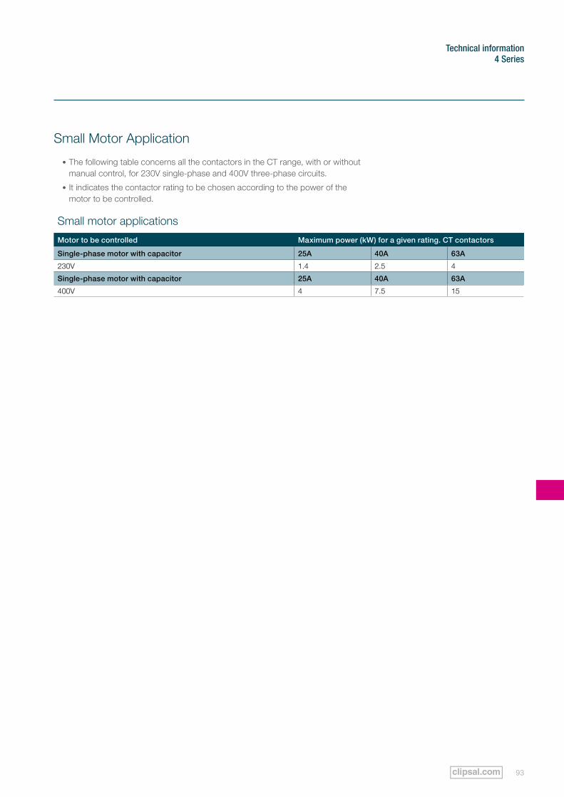
93
Technical information4 Series
Small Motor Application
•The following table concerns all the contactors in the CT range, with or without manual control, for 230V single-phase and 400V three-phase circuits.
•It indicates the contactor rating to be chosen according to the power of the motor to be controlled.
Small motor applications
Motor to be controlled Maximum power (kW) for a given rating. CT contactors
Single-phase motor with capacitor 25A 40A 63A
230V 1.4 2.5 4
Single-phase motor with capacitor 25A 40A 63A
400V 4 7.5 15
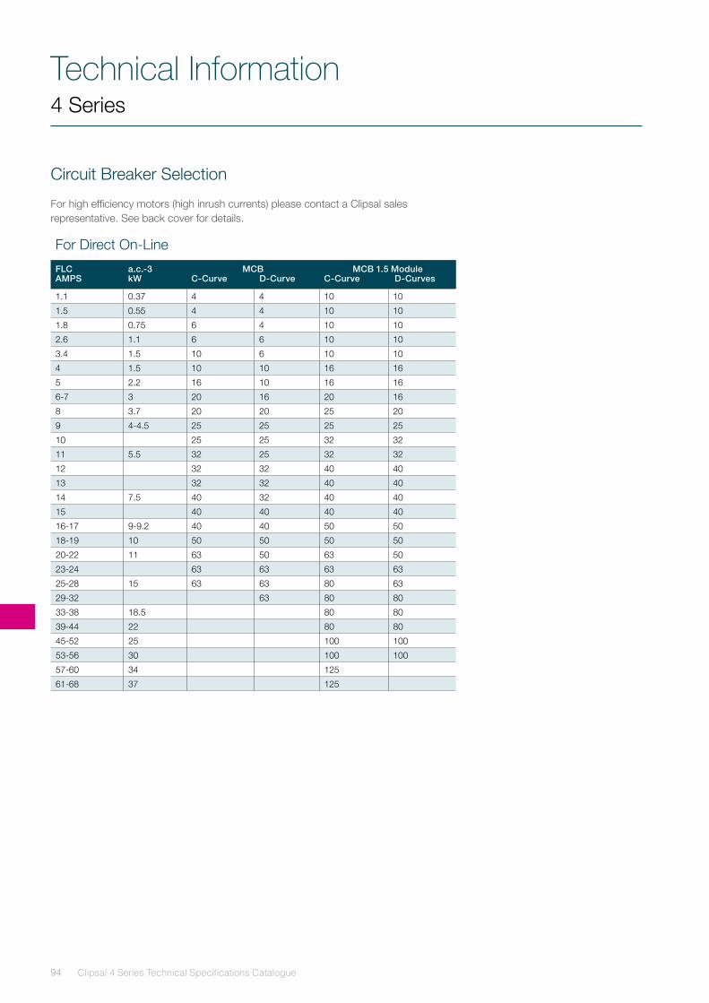
Clipsal 4 Series Technical Specifications Catalogue94
Technical Information
For Direct On-Line
FLCAMPS
a.c.-3kW
MCBC-Curve D-Curve
MCB 1.5 ModuleC-Curve D-Curves
1.1 0.37 4 4 10 10
1.5 0.55 4 4 10 10
1.8 0.75 6 4 10 10
2.6 1.1 6 6 10 10
3.4 1.5 10 6 10 10
4 1.5 10 10 16 16
5 2.2 16 10 16 16
6-7 3 20 16 20 16
8 3.7 20 20 25 20
9 4-4.5 25 25 25 25
10 25 25 32 32
11 5.5 32 25 32 32
12 32 32 40 40
13 32 32 40 40
14 7.5 40 32 40 40
15 40 40 40 40
16-17 9-9.2 40 40 50 50
18-19 10 50 50 50 50
20-22 11 63 50 63 50
23-24 63 63 63 63
25-28 15 63 63 80 63
29-32 63 80 80
33-38 18.5 80 80
39-44 22 80 80
45-52 25 100 100
53-56 30 100 100
57-60 34 125
61-68 37 125
4 Series
Circuit Breaker Selection
For high efficiency motors (high inrush currents) please contact a Clipsal sales representative. See back cover for details.
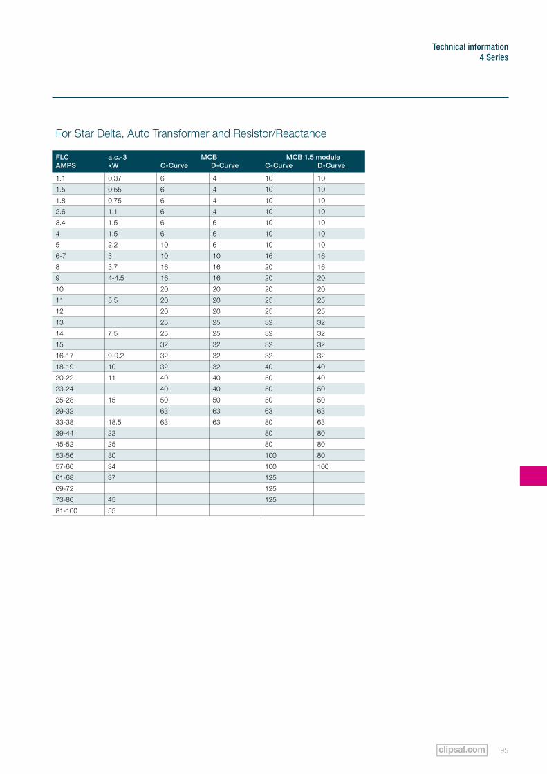
95
Technical information4 Series
For Star Delta, Auto Transformer and Resistor/Reactance
FLCAMPS
a.c.-3kW
MCBC-Curve D-Curve
MCB 1.5 moduleC-Curve D-Curve
1.1 0.37 6 4 10 10
1.5 0.55 6 4 10 10
1.8 0.75 6 4 10 10
2.6 1.1 6 4 10 10
3.4 1.5 6 6 10 10
4 1.5 6 6 10 10
5 2.2 10 6 10 10
6-7 3 10 10 16 16
8 3.7 16 16 20 16
9 4-4.5 16 16 20 20
10 20 20 20 20
11 5.5 20 20 25 25
12 20 20 25 25
13 25 25 32 32
14 7.5 25 25 32 32
15 32 32 32 32
16-17 9-9.2 32 32 32 32
18-19 10 32 32 40 40
20-22 11 40 40 50 40
23-24 40 40 50 50
25-28 15 50 50 50 50
29-32 63 63 63 63
33-38 18.5 63 63 80 63
39-44 22 80 80
45-52 25 80 80
53-56 30 100 80
57-60 34 100 100
61-68 37 125
69-72 125
73-80 45 125
81-100 55
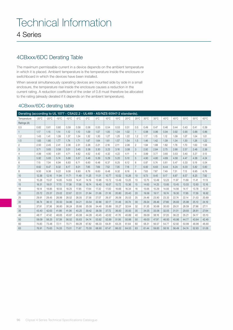
Clipsal 4 Series Technical Specifications Catalogue96
Technical Information4 Series
4CBxxx/6DC Derating Table
The maximum permissable current in a device depends on the ambient temperature in which it is placed. Ambient temperature is the temperature inside the enclosure or switchboard in which the devices have been installed.
When several simultaneously operating devices are mounted side by side in a small enclosure, the temperature rise inside the enclosure causes a reduction in the current rating. A reduction coefficient of the order of 0.8 must therefore be allocated to the rating (already derated if it depends on the ambient temperature).
4CBxxx/6DC derating table
Derating (according to UL 1077 - CSA22.2 - UL489 - AS/NZS 60947-2 standards).
Temperature -25°C -20°C -15°C -10°C -5°C 0°C 5°C 10°C 15°C 20°C 25°C 30°C 35°C 40°C 45°C 50°C 55°C 60°C
Ratings (A)
0.5 0.62 0.61 0.60 0.59 0.58 0.56 0.55 0.54 0.53 0.51 0.5 0.49 0.47 0.46 0.44 0.43 0.41 0.39
1 1.17 1.15 1.14 1.12 1.10 1.09 1.07 1.05 1.04 1.02 1 0.98 0.96 0.94 0.92 0.90 0.88 0.86
1.2 1.43 1.41 1.39 1.37 1.34 1.32 1.30 1.27 1.25 1.22 1.2 1.17 1.15 1.12 1.09 1.07 1.04 1.01
1.5 1.83 1.80 1.77 1.74 1.71 1.67 1.64 1.61 1.57 1.54 1.5 1.46 1.42 1.39 1.34 1.30 1.26 1.22
2 2.50 2.45 2.41 2.36 2.31 2.26 2.21 2.16 2.11 2.06 2 1.94 1.88 1.82 1.76 1.70 1.63 1.56
3 3.71 3.65 3.58 3.51 3.45 3.38 3.30 3.23 3.16 3.08 3 2.92 2.84 2.75 2.66 2.57 2.48 2.38
4 4.99 4.90 4.81 4.71 4.62 4.52 4.42 4.32 4.22 4.11 4 3.89 3.77 3.65 3.53 3.40 3.27 3.13
5 5.92 5.83 5.74 5.66 5.57 5.48 5.39 5.29 5.20 5.10 5 4.90 4.80 4.69 4.58 4.47 4.36 4.24
6 7.15 7.04 6.94 6.83 6.71 6.60 6.48 6.37 6.25 6.12 6 5.87 5.74 5.61 5.47 5.33 5.19 5.04
7 8.62 8.47 8.32 8.17 8.01 7.85 7.69 7.52 7.35 7.18 7 6.82 6.63 6.44 6.24 6.03 5.82 5.60
8 9.50 9.36 9.22 9.08 8.93 8.78 8.63 8.48 8.32 8.16 8 7.83 7.67 7.49 7.31 7.13 6.95 6.76
10 12.38 12.16 11.94 11.71 11.49 11.25 11.01 10.77 10.52 10.26 10 9.73 9.45 9.17 8.87 8.57 8.25 7.92
13 15.28 15.07 14.85 14.63 14.41 14.19 13.96 13.72 13.49 13.25 13 12.75 12.49 12.23 11.97 11.69 11.41 11.13
15 18.31 18.01 17.70 17.38 17.06 16.74 16.40 16.07 15.72 15.36 15 14.63 14.25 13.85 13.45 13.03 12.60 12.16
16 19.14 18.85 18.55 18.25 17.95 17.64 17.32 17.00 16.68 16.34 16 15.65 15.29 14.93 14.56 14.17 13.78 13.37
20 23.72 23.37 23.02 22.67 22.31 21.94 21.56 21.18 20.80 20.40 20 19.59 19.17 18.74 18.30 17.85 17.39 16.92
25 29.91 29.45 28.99 28.52 28.05 27.56 27.07 26.57 26.06 25.53 25 24.46 23.90 23.33 22.74 22.14 21.53 20.89
30 36.74 36.12 35.50 34.86 34.21 33.54 32.86 32.17 31.46 30.74 30 29.24 28.46 27.66 26.83 25.98 25.10 24.19
32 37.91 37.36 36.80 36.24 35.66 35.08 34.48 33.88 33.27 32.64 32 31.35 30.68 30.00 29.31 28.59 27.86 27.11
35 43.40 42.63 41.86 41.06 40.25 39.42 38.58 37.72 36.83 35.93 35 34.05 33.06 32.05 31.01 29.93 28.81 27.64
40 48.17 47.42 46.65 45.87 45.08 44.28 43.45 42.62 41.76 40.89 40 39.09 38.16 37.20 36.22 35.21 34.17 33.10
50 59.09 58.25 57.39 56.52 55.63 54.74 53.82 52.89 51.95 50.98 50 49.00 47.97 46.93 45.86 44.77 43.64 42.49
60 74.83 73.48 72.11 70.71 69.28 67.82 66.33 64.81 63.25 61.64 60 58.31 56.57 54.77 52.92 50.99 48.99 46.90
63 76.91 75.63 74.33 73.01 71.67 70.30 68.90 67.47 66.02 64.53 63 61.44 59.83 58.18 56.49 54.74 52.93 51.06
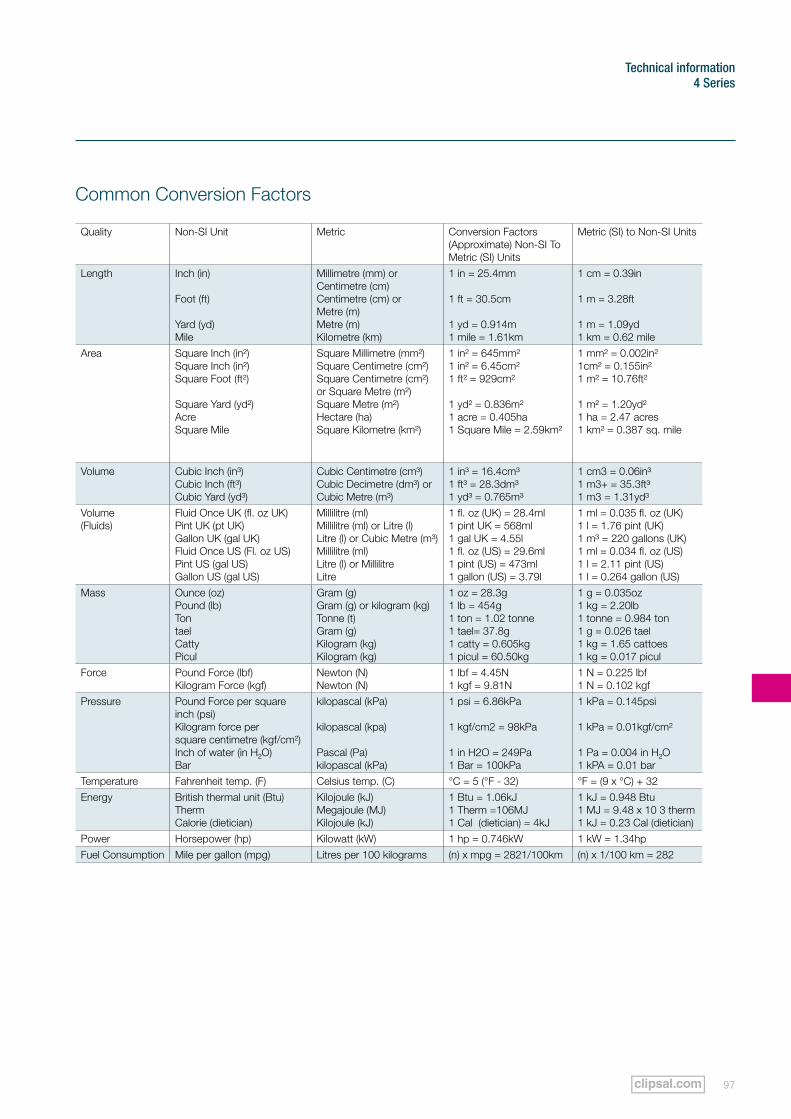
97
Technical information4 Series
Common Conversion Factors
Quality Non-SI Unit Metric Conversion Factors (Approximate) Non-SI To Metric (SI) Units
Metric (SI) to Non-SI Units
Length Inch (in)
Foot (ft)
Yard (yd)Mile
Millimetre (mm) orCentimetre (cm)Centimetre (cm) or Metre (m)Metre (m)Kilometre (km)
1 in = 25.4mm
1 ft = 30.5cm
1 yd = 0.914m1 mile = 1.61km
1 cm = 0.39in
1 m = 3.28ft
1 m = 1.09yd1 km = 0.62 mile
Area Square Inch (in²)Square Inch (in²)Square Foot (ft²)
Square Yard (yd²)AcreSquare Mile
Square Millimetre (mm²)Square Centimetre (cm²)Square Centimetre (cm²)or Square Metre (m²)Square Metre (m²)Hectare (ha)Square Kilometre (km²)
1 in² = 645mm²1 in² = 6.45cm²1 ft² = 929cm²
1 yd² = 0.836m²1 acre = 0.405ha1 Square Mile = 2.59km²
1 mm² = 0.002in²1cm² = 0.155in²1 m² = 10.76ft²
1 m² = 1.20yd²1 ha = 2.47 acres1 km² = 0.387 sq. mile
Volume Cubic Inch (in³)Cubic Inch (ft³)Cubic Yard (yd³)
Cubic Centimetre (cm³)Cubic Decimetre (dm³) orCubic Metre (m³)
1 in³ = 16.4cm³1 ft³ = 28.3dm³1 yd³ = 0.765m³
1 cm3 = 0.06in³1 m3+ = 35.3ft³ 1 m3 = 1.31yd³
Volume(Fluids)
Fluid Once UK (fl. oz UK)Pint UK (pt UK)Gallon UK (gal UK)Fluid Once US (Fl. oz US)Pint US (gal US)Gallon US (gal US)
Millilitre (ml)Millilitre (ml) or Litre (l)Litre (l) or Cubic Metre (m³)Millilitre (ml)Litre (l) or MillilitreLitre
1 fl. oz (UK) = 28.4ml1 pint UK = 568ml1 gal UK = 4.55l1 fl. oz (US) = 29.6ml1 pint (US) = 473ml1 gallon (US) = 3.79l
1 ml = 0.035 fl. oz (UK)1 l = 1.76 pint (UK)1 m³ = 220 gallons (UK)1 ml = 0.034 fl. oz (US)1 l = 2.11 pint (US)1 l = 0.264 gallon (US)
Mass Ounce (oz)Pound (lb)TontaelCattyPicul
Gram (g)Gram (g) or kilogram (kg)Tonne (t)Gram (g)Kilogram (kg)Kilogram (kg)
1 oz = 28.3g1 lb = 454g1 ton = 1.02 tonne1 tael= 37.8g1 catty = 0.605kg1 picul = 60.50kg
1 g = 0.035oz1 kg = 2.20lb1 tonne = 0.984 ton1 g = 0.026 tael1 kg = 1.65 cattoes1 kg = 0.017 picul
Force Pound Force (lbf)Kilogram Force (kgf)
Newton (N)Newton (N)
1 lbf = 4.45N1 kgf = 9.81N
1 N = 0.225 lbf1 N = 0.102 kgf
Pressure Pound Force per squareinch (psi)Kilogram force persquare centimetre (kgf/cm²)Inch of water (in H²O)Bar
kilopascal (kPa)
kilopascal (kpa)
Pascal (Pa)kilopascal (kPa)
1 psi = 6.86kPa
1 kgf/cm2 = 98kPa
1 in H2O = 249Pa1 Bar = 100kPa
1 kPa = 0.145psi
1 kPa = 0.01kgf/cm²
1 Pa = 0.004 in H²O1 kPA = 0.01 bar
Temperature Fahrenheit temp. (F) Celsius temp. (C) °C = 5 (°F - 32) °F = (9 x °C) + 32Energy British thermal unit (Btu)
ThermCalorie (dietician)
Kilojoule (kJ)Megajoule (MJ)Kilojoule (kJ)
1 Btu = 1.06kJ1 Therm =106MJ1 Cal (dietician) = 4kJ
1 kJ = 0.948 Btu1 MJ = 9.48 x 10 3 therm1 kJ = 0.23 Cal (dietician)
Power Horsepower (hp) Kilowatt (kW) 1 hp = 0.746kW 1 kW = 1.34hpFuel Consumption Mile per gallon (mpg) Litres per 100 kilograms (n) x mpg = 2821/100km (n) x 1/100 km = 282
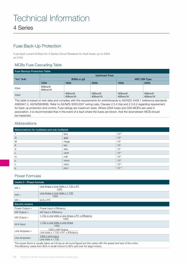
Clipsal 4 Series Technical Specifications Catalogue98
Technical Information4 Series
Fuse Back-Up Protection
Fuse fault current limiters for 4 Series Circuit Breakers for fault levels up to 50kA at 415V.
MCBs Fuse Cascading Table
Fuse Backup Protection Table
“Icc” (kA)Upstream Fuse
BS88 or gG HRC DIN Type125A 160A 200A 160A 200A
63kA4CBxxx/6 4CBxxx/10
50kA4CBxxx/6 4CBxxx/10
4CBxxx/6 4CBxxx/10
4CBxxx/6 4CBxxx/10
4CBxxx/6 4CBxxx/10
This table is based on test data and complies with the requirements for switchboards to AS/NZS 3439.1 (reference standards AS60947.2, AS/NZS60898). Refer to AS/NZS 3000:2007 wiring rules, Clauses 2.5.4.5(a) and 2.5.6.2 regarding requirement for back up protection and control. Fuse ratings are maximum sizes. Where 200A fuses and C60 MCB’s are used in association, it is recommended that in the event of a fault where the fuses are blown, that the downstream MCB should be inspected.
Abbreviations
Abbreviations for multiples and sub multiples
T tera 1012
G giga 109
M mega 106
K kilo 103
d deci 10-1
c centi 10-2
m milli 10-3
µ micro 10-6
n nano 10-9
p pico 10-12
Power Formulas
Useful 3 - Phase formula
kW = Line Amps x Line Volts x 1.732 x P.F. 1000
kVA = Line Amps x Line Volts x 1.732 1000
kW = kV.A x P.F.
Electric motors
Power Output = Power Input x EfficiencykW Output = kW Input x Efficiency
kW Output = 1.732 x Line Volts x Line Amps x P.F. x Efficiency 1000
kV.A Input 1.732 x Line Volts x Line Amps 1000
Line Amperes = 1000 x kW Output Line Volts x 1.732 x P.F. x Efficiency
Line Amperes= 1000 x kV.A InputLine Volts x 1.732
The power factor is usually taken as 0.8 (as an all-round figure) but this varies with the speed and size of the motor.The efficiency varies from 85% in small motors to 90% and over for large motors.
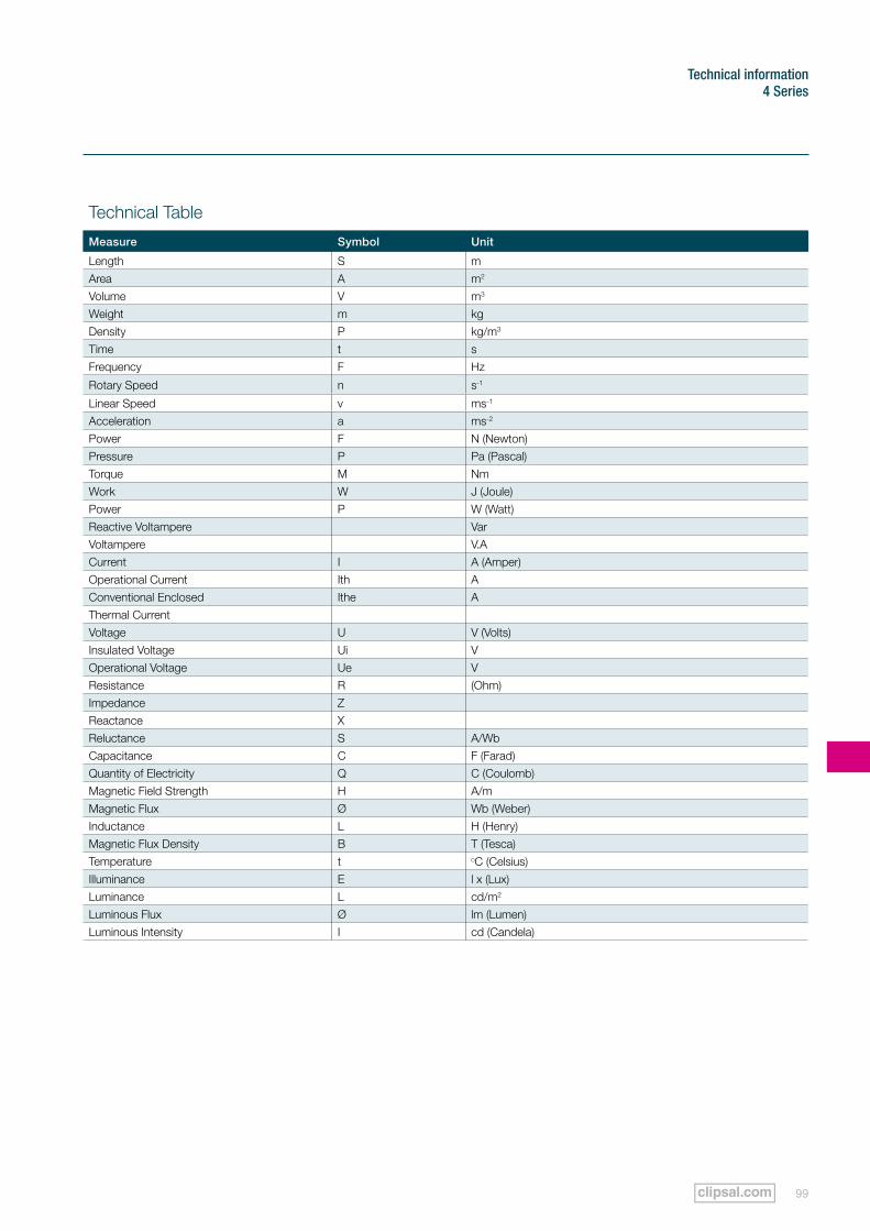
99
Technical information4 Series
Technical Table
Measure Symbol Unit
Length S mArea A m2
Volume V m3
Weight m kgDensity P kg/m3
Time t sFrequency F Hz
Rotary Speed n s-1
Linear Speed v ms-1
Acceleration a ms-2
Power F N (Newton)Pressure P Pa (Pascal)Torque M NmWork W J (Joule)Power P W (Watt)Reactive Voltampere VarVoltampere V.ACurrent I A (Amper)Operational Current Ith AConventional Enclosed Ithe AThermal CurrentVoltage U V (Volts)Insulated Voltage Ui VOperational Voltage Ue VResistance R (Ohm)Impedance ZReactance XReluctance S A/WbCapacitance C F (Farad)Quantity of Electricity Q C (Coulomb)Magnetic Field Strength H A/mMagnetic Flux Ø Wb (Weber)Inductance L H (Henry)Magnetic Flux Density B T (Tesca)Temperature t oC (Celsius)Illuminance E l x (Lux)Luminance L cd/m2
Luminous Flux Ø lm (Lumen)Luminous Intensity I cd (Candela)
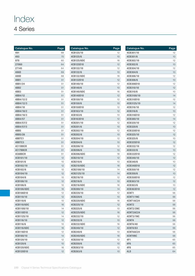
Clipsal 4 Series Technical Specifications Catalogue100
Index4 Series
Catalogue No. Page Catalogue No. PageCatalogue No. Page
491 68
493 70
970 60
27060 64
27145 64
486D 69
489D 68
4BB1 51
4BB1/24 51
4BB2 51
4BB3 51
4BB4/12 51
4BB4/12/2 51
4BB4/12/3 51
4BB4/18 51
4BB4/18/2 51
4BB4/18/3 51
4BB4/57 51
4BB4/57/2 51
4BB4/57/3 51
4BB5 51
4BB5/26 51
4BBTC1 51
4BBTC3 51
4C11BBCR 51
4C17BBCR 51
4C6BBCR 51
4CB101/10 12
4CB101/6 10
4CB102/10 12
4CB102/6 10
4CB104/10 12
4CB104/6 10
4CB106/10 12
4CB106/6 10
4CB106/6DC 16
4CB106D10 12
4CB110/10 12
4CB110/6 10
4CB110/6DC 16
4CB1100/10 14
4CB110D10 12
4CB1125/10 14
4CB116/10 12
4CB116/6 10
4CB116/6DC 16
4CB116D10 12
4CB180/10 14
4CB120/10 12
4CB120/6 10
4CB120/6DC 16
4CB120D10 12
4CB125/10 12
4CB125/6 10
4CB125/6DC 16
4CB125D10 12
4CB132/10 12
4CB132/6 10
4CB132/6DC 16
4CB132D10 12
4CB140/10 12
4CB140/6 10
4CB140/6DC 16
4CB140D10 12
4CB150/10 12
4CB150/6 10
4CB150D10 12
4CB163/10 12
4CB163/6 10
4CB163D10 12
4CB201/10 12
4CB201/6 10
4CB202/10 12
4CB202/6 10
4CB204/10 12
4CB204/6 10
4CB206/10 12
4CB206/6 10
4CB206/6DC 16
4CB210/10 12
4CB210/6 10
4CB210/6DC 16
4CB2100/10 14
4CB2125/10 14
4CB216/10 12
4CB216/6 10
4CB216/6DC 16
4CB280/10 14
4CB220/10 12
4CB220/6 10
4CB220/6DC 16
4CB225/10 12
4CB225/6 10
4CB225/6DC 16
4CB232/10 12
4CB232/6 10
4CB232/6DC 16
4CB240/10 12
4CB240/6 10
4CB240/6DC 16
4CB250/10 12
4CB250/6 10
4CB263/10 12
4CB263/6 10
4CB301/10 12
4CB301/6 10
4CB302/10 12
4CB302/6 10
4CB304/10 12
4CB304/6 10
4CB306/10 12
4CB306/6 10
4CB306D10 12
4CB310/10 12
4CB310/6 10
4CB3100/10 14
4CB310D10 12
4CB3125/10 14
4CB316/10 12
4CB316/6 10
4CB316D10 12
4CB380/10 14
4CB320/10 12
4CB320/6 10
4CB320D10 12
4CB325/10 12
4CB325/6 10
4CB325D10 12
4CB332/10 12
4CB332/6 10
4CB332D10 12
4CB340/10 12
4CB340/6 10
4CB340D10 12
4CB350/10 12
4CB350/6 10
4CB350D10 12
4CB363/10 12
4CB363/6 10
4CB363D10 12
4CNT1 56
4CNT1/1NC 56
4CNT1AC24 56
4CNT2 56
4CNT2/2NC 56
4CNT2AC24 56
4CNT3/1NC 56
4CNT4 56
4CNT4/40 56
4CNT4/63 56
4CNT4AC24 56
4CNT4NC 56
4F1 65
4F6 65
4F8 65
4LD 64
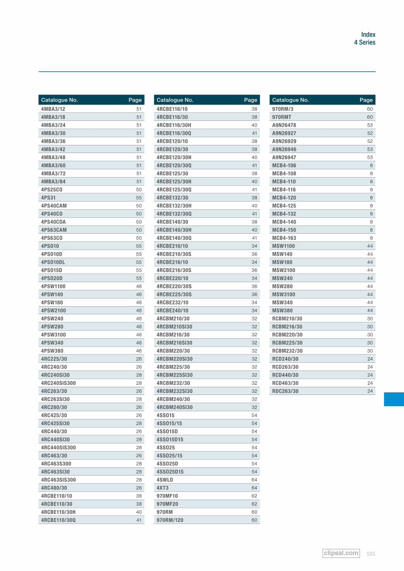
101
Index 4 Series
Catalogue No. Page Catalogue No. PageCatalogue No. Page
4MBA3/12 51
4MBA3/18 51
4MBA3/24 51
4MBA3/30 51
4MBA3/36 51
4MBA3/42 51
4MBA3/48 51
4MBA3/60 51
4MBA3/72 51
4MBA3/84 51
4PS25CO 50
4PS31 55
4PS40CAM 50
4PS40CO 50
4PS40COA 50
4PS63CAM 50
4PS63CO 50
4PSO10 55
4PSO10D 55
4PSO10DL 55
4PSO15D 55
4PSO20D 55
4PSW1100 46
4PSW140 46
4PSW180 46
4PSW2100 46
4PSW240 46
4PSW280 46
4PSW3100 46
4PSW340 46
4PSW380 46
4RC225/30 26
4RC240/30 26
4RC240SI30 28
4RC240SIS300 28
4RC263/30 26
4RC263SI30 28
4RC280/30 26
4RC425/30 26
4RC425SI30 28
4RC440/30 26
4RC440SI30 28
4RC440SIS300 28
4RC463/30 26
4RC463S300 28
4RC463SI30 28
4RC463SIS300 28
4RC480/30 26
4RCBE110/10 38
4RCBE110/30 38
4RCBE110/30H 40
4RCBE110/30Q 41
4RCBE116/10 38
4RCBE116/30 38
4RCBE116/30H 40
4RCBE116/30Q 41
4RCBE120/10 38
4RCBE120/30 38
4RCBE120/30H 40
4RCBE120/30Q 41
4RCBE125/30 38
4RCBE125/30H 40
4RCBE125/30Q 41
4RCBE132/30 38
4RCBE132/30H 40
4RCBE132/30Q 41
4RCBE140/30 38
4RCBE140/30H 40
4RCBE140/30Q 41
4RCBE210/10 34
4RCBE210/30S 36
4RCBE216/10 34
4RCBE216/30S 36
4RCBE220/10 34
4RCBE220/30S 36
4RCBE225/30S 36
4RCBE232/10 34
4RCBE240/10 34
4RCBM210/30 32
4RCBM210SI30 32
4RCBM216/30 32
4RCBM216SI30 32
4RCBM220/30 32
4RCBM220SI30 32
4RCBM225/30 32
4RCBM225SI30 32
4RCBM232/30 32
4RCBM232SI30 32
4RCBM240/30 32
4RCBM240SI30 32
4SSO15 54
4SSO15/15 54
4SSO15D 54
4SSO15D15 54
4SSO25 54
4SSO25/15 54
4SSO25D 54
4SSO25D15 54
4SWLD 64
4XT3 64
970MF10 62
970MF20 62
970RM 60
970RM/120 60
970RM/3 60
970RMT 60
A9N26478 53
A9N26927 52
A9N26929 52
A9N26946 53
A9N26947 53
MCB4-106 8
MCB4-108 8
MCB4-110 8
MCB4-116 8
MCB4-120 8
MCB4-125 8
MCB4-132 8
MCB4-140 8
MCB4-150 8
MCB4-163 8
MSW1100 44
MSW140 44
MSW180 44
MSW2100 44
MSW240 44
MSW280 44
MSW3100 44
MSW340 44
MSW380 44
RCBM210/30 30
RCBM216/30 30
RCBM220/30 30
RCBM225/30 30
RCBM232/30 30
RCD240/30 24
RCD263/30 24
RCD440/30 24
RCD463/30 24
RDC263/30 24
Clipsal 4 Series Technical Specifications Catalogue102
Notes4 Series
103
Notes 4 Series
© 2011 Schneider Electric. All Rights Reserved.
Trademarks are owned by Schneider Electric Industries SAS or its affiliated companies.
You can find this brochure and many others online in PDF format at: clipsal.comFollow the links off the home page or access the following page directly: clipsal.com/brochures
Schneider Electric (Australia) Pty Ltd reserves the right to change specifications, modify designs and discontinue items without incurring obligation and whilst every effort is made to ensure that descriptions, specifications and other information in this catalogue are correct, no warranty is given in respect thereof and the company shall not be liable for any error therein.
C3-
013
Schneider Electric (Australia) Pty Ltd
33-37 Port Wakefield Road, Gepps Cross, South Australia 5094
PO Box 132, Enfield Plaza, South Australia 5085
Telephone: (08) 8161 0511 Facsimile: (08) 8161 0900 Email: [email protected] Internet: www.clipsal.com
National Customer Care Enquiries: 1300 2025 25National Customer Care Facsimile: 1300 2025 56
International Enquiries International Sales and Marketing Email: [email protected]
Schneider Electric (NZ) Ltd38 Business Parade South, Highbrook, East Tamaki, Manukau 2013, NEW ZEALAND
Telephone: + 64 9 829 0490Facsimile: + 64 9 829 0491Internet: www.schneider-electric.co.nz
Customer CareFreephone: 0800 652 999Freefax: 0800 101 152Email: [email protected] Internet: www.clipsal.co.nz
O/N 23276CLIPCOM 23276 November 2011
printed on recycled paper