Embed Size (px)
DESCRIPTION
4-TH CONCEPT MDI ISSUES update. Alexander Mikhailichenko, Cornell University John Hauptman, Iowa University For 4-th Collaboration http://physics.uoregon.edu/~lc/wwstudy/concepts/. LCWS08, November 15-20, 2008 –Chicago. - PowerPoint PPT Presentation
Citation preview
1
Alexander Mikhailichenko, Cornell University
John Hauptman, Iowa University
For 4-th Collaboration
http://physics.uoregon.edu/~lc/wwstudy/concepts/
4-TH CONCEPT MDI ISSUESupdate
LCWS08, November 15-20, 2008 –Chicago
2
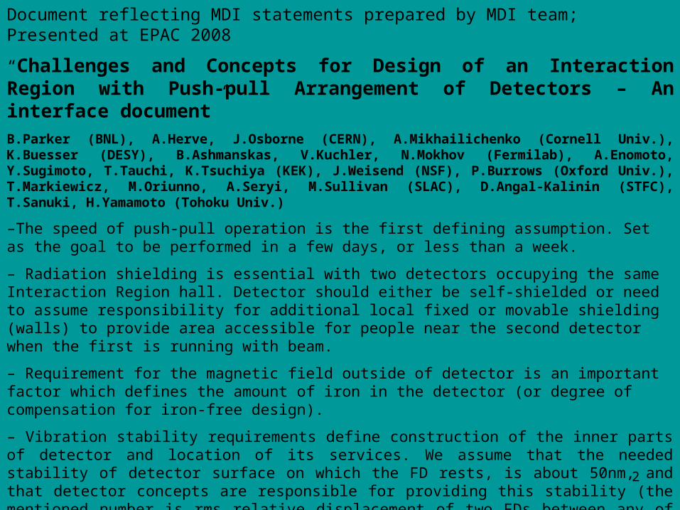
Document reflecting MDI statements prepared by MDI team; Presented at EPAC 2008
“Challenges and Concepts for Design of an Interaction Region with Push-pull Arrangement of Detectors – An interface document”B.Parker (BNL), A.Herve, J.Osborne (CERN), A.Mikhailichenko (Cornell Univ.), K.Buesser (DESY), B.Ashmanskas, V.Kuchler, N.Mokhov (Fermilab), A.Enomoto, Y.Sugimoto, T.Tauchi, K.Tsuchiya (KEK), J.Weisend (NSF), P.Burrows (Oxford Univ.), T.Markiewicz, M.Oriunno, A.Seryi, M.Sullivan (SLAC), D.Angal-Kalinin (STFC), T.Sanuki, H.Yamamoto (Tohoku Univ.)
–The speed of push-pull operation is the first defining assumption. Set as the goal to be performed in a few days, or less than a week.
– Radiation shielding is essential with two detectors occupying the same Interaction Region hall. Detector should either be self-shielded or need to assume responsibility for additional local fixed or movable shielding (walls) to provide area accessible for people near the second detector when the first is running with beam.
– Requirement for the magnetic field outside of detector is an important factor which defines the amount of iron in the detector (or degree of compensation for iron-free design).
– Vibration stability requirements define construction of the inner parts of detector and location of its services. We assume that the needed stability of detector surface on which the FD rests, is about 50nm, and that detector concepts are responsible for providing this stability (the mentioned number is rms relative displacement of two FDs between any of 5Hz pulses). This also assumes that final stability of the Final Doublet would be about 100nm and the difference constitutes the machine vibration budget. – For reference, the detector has its own internal alignment requirements, which typically involve measuring Vertex position with respect to tracker on a micron level, and measuring tracker to calorimeter on mm level.
3
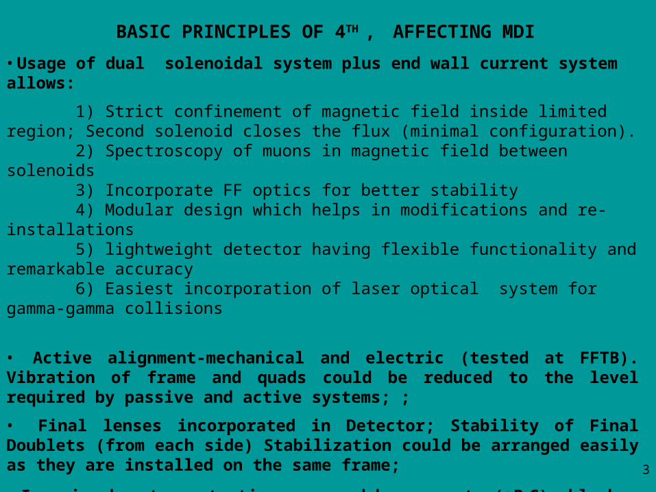
• Usage of dual solenoidal system plus end wall current system allows:
1) Strict confinement of magnetic field inside limited region; Second solenoid closes the flux (minimal configuration). 2) Spectroscopy of muons in magnetic field between solenoids 3) Incorporate FF optics for better stability 4) Modular design which helps in modifications and re-installations 5) lightweight detector having flexible functionality and remarkable accuracy 6) Easiest incorporation of laser optical system for gamma-gamma collisions
• Active alignment-mechanical and electric (tested at FFTB). Vibration of frame and quads could be reduced to the level required by passive and active systems; ;
• Final lenses incorporated in Detector; Stability of Final Doublets (from each side) Stabilization could be arranged easily as they are installed on the same frame;
• Iron is absent; protection arranged by concrete (+B4C) blocks surrounded;
• Light weight allows easy transportation and pre-alignment;
• Push-pull concept satisfied easily; no platform required;
BASIC PRINCIPLES OF 4TH , AFFECTING MDI

4
CONCEPTS OF FF OPTICS INSTALLATION AND BASEMENT
Active systems for positioning include
• Stepping motor-driven micro-positioning movers (tested at FFTB);
• Piezoelectric fast movers with active feedback;
• Dipole windings in each quadrupole for equivalent shift of quadrupole axis in both transverse directions (tested at FFTB).
worsen
better
Basement to the Detector
Basement to the ground
Attachment of cryostat with QF1 to the detector frame could be done after positioning detector in place
5
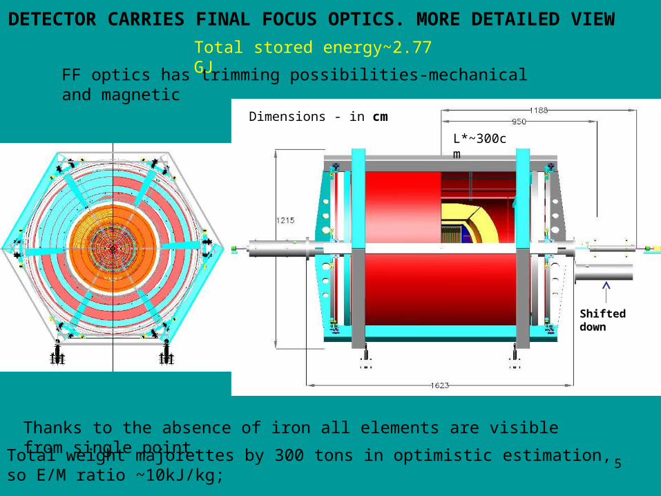
DETECTOR CARRIES FINAL FOCUS OPTICS. MORE DETAILED VIEW
Total weight majorettes by 300 tons in optimistic estimation, so E/M ratio ~10kJ/kg;
1000 T in conservative estimation (traditional coil design)
FF optics has trimming possibilities-mechanical and magnetic
Total stored energy~2.77 GJ
Thanks to the absence of iron all elements are visible from single point.
Shifted down
L*~300cm
Dimensions - in cm
6
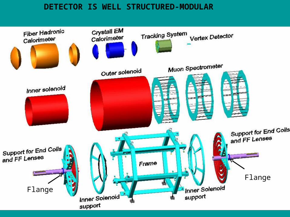
DETECTOR IS WELL STRUCTURED-MODULAR
Flange
Flange
7
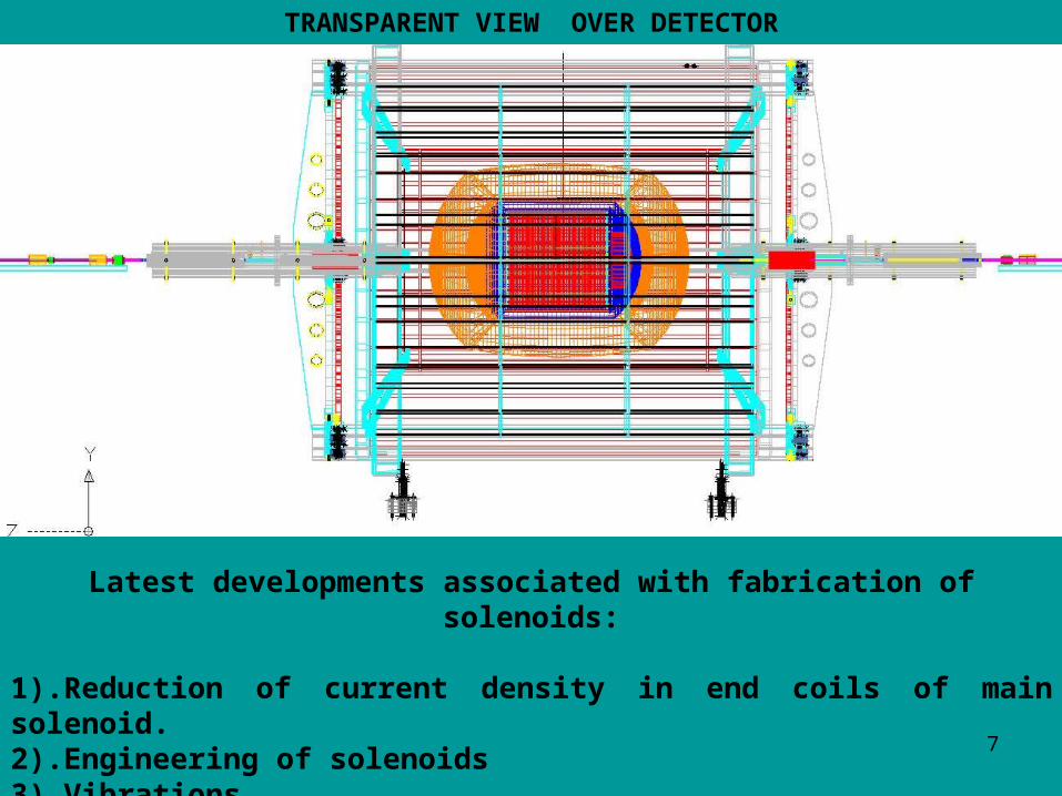
TRANSPARENT VIEW OVER DETECTOR
Latest developments associated with fabrication of solenoids:
1).Reduction of current density in end coils of main solenoid. 2).Engineering of solenoids3).Vibrations
8
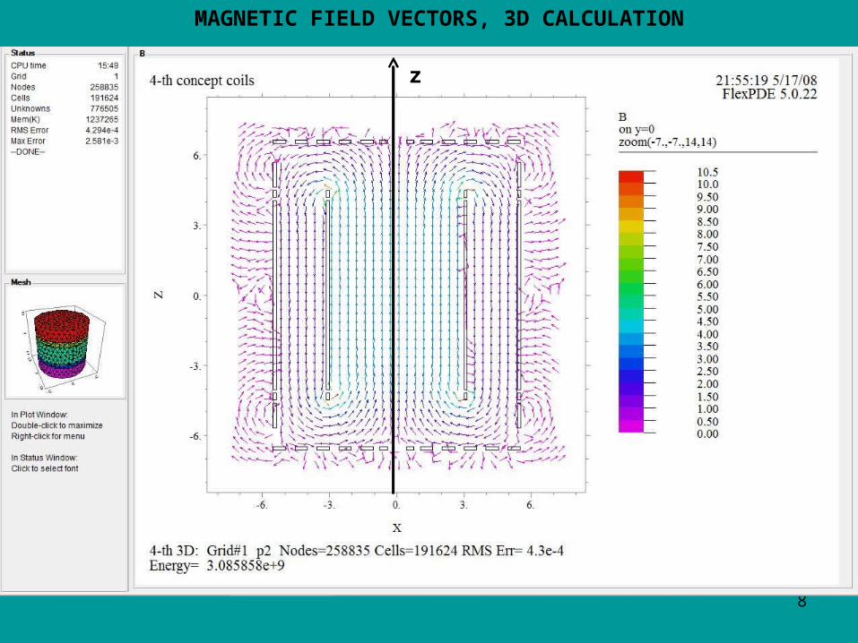
MAGNETIC FIELD VECTORS, 3D CALCULATION
z
9
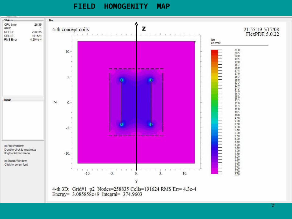
FIELD HOMOGENITY MAP
z
10
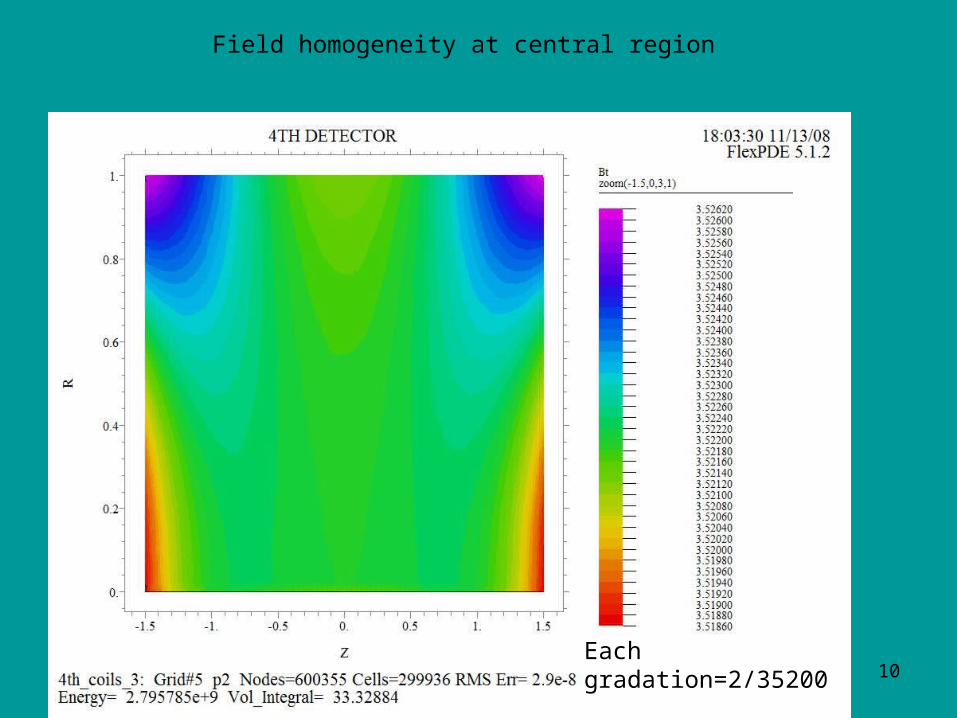
Field homogeneity at central region
Each gradation=2/35200

11
WE APPROACCHING ENGINEERING STAGE IN COIL DESIGN
Coil design;
Type of cable, wire;
Tests need to be carried;
Technologies need to be revisited;
Structural composition of solenoids;
Mechanical stability;
Wall coils-room temperature. Adjust current density and dimensions;
Quench protection (coils, electronics and all inner systems)
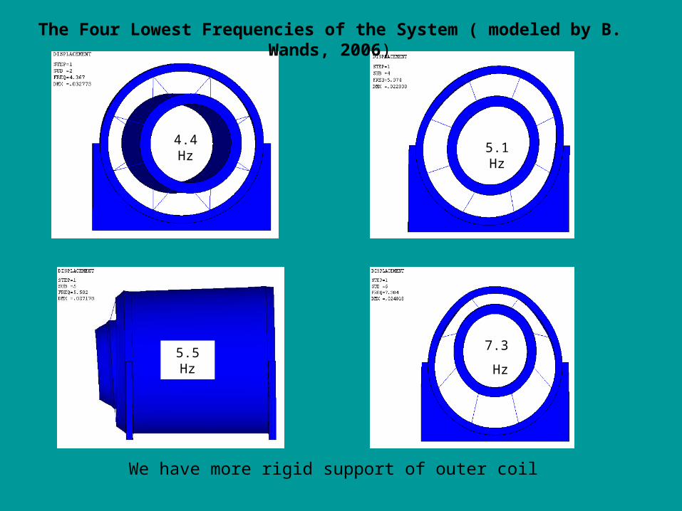
4.4 Hz5.1 Hz
5.5 Hz7.3
Hz
The Four Lowest Frequencies of the System ( modeled by B. Wands, 2006)
We have more rigid support of outer coil
13
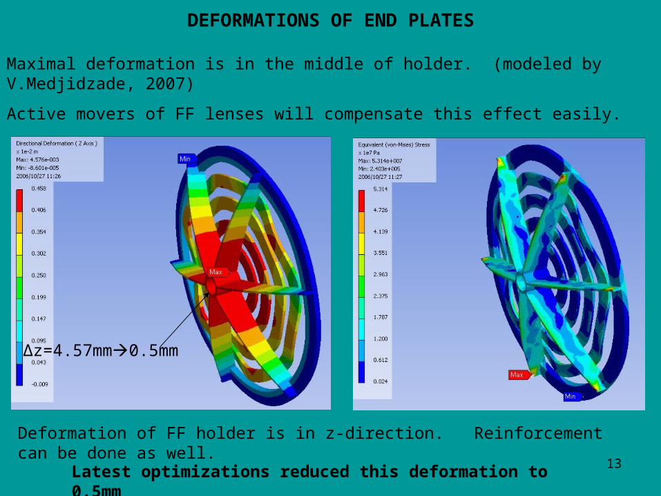
DEFORMATIONS OF END PLATES
Latest optimizations reduced this deformation to 0.5mm
Maximal deformation is in the middle of holder. (modeled by V.Medjidzade, 2007)
Active movers of FF lenses will compensate this effect easily.
Deformation of FF holder is in z-direction. Reinforcement can be done as well.
Δz=4.57mm0.5mm
14
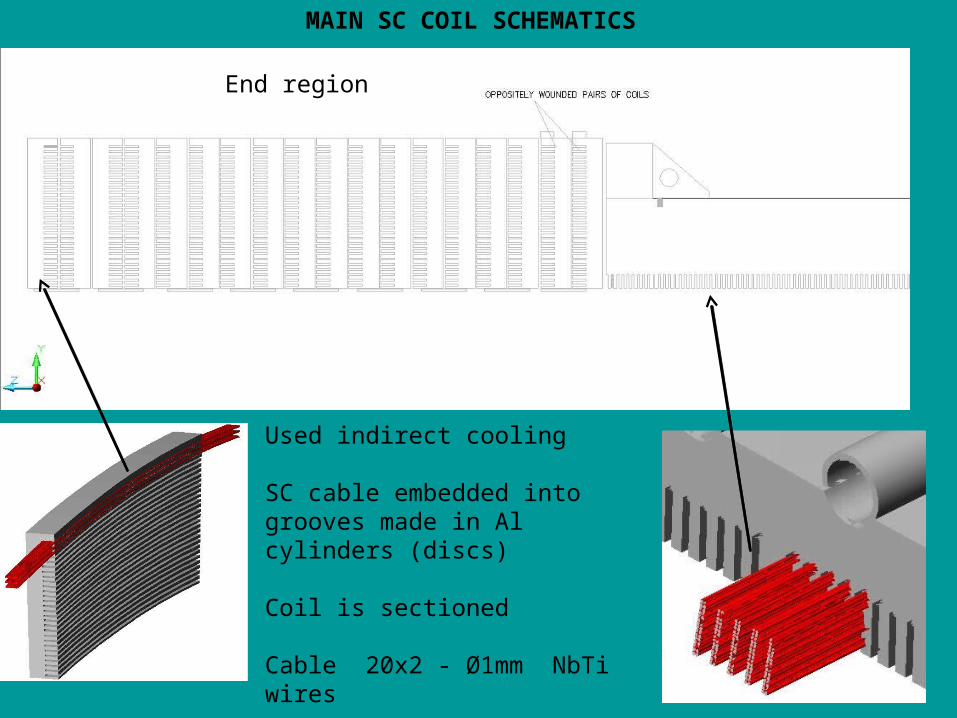
MAIN SC COIL SCHEMATICS
End region
Used indirect cooling
SC cable embedded into grooves made in Al cylinders (discs)
Coil is sectioned
Cable 20x2 - Ø1mm NbTi wires
15
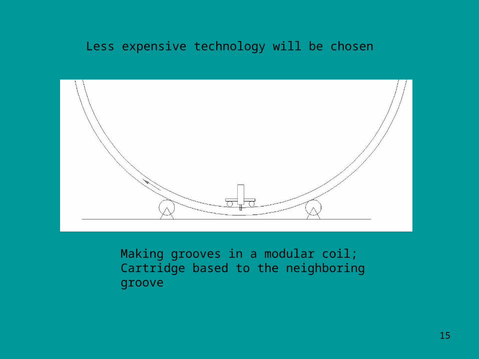
Less expensive technology will be chosen
Making grooves in a modular coil;Cartridge based to the neighboring groove
16
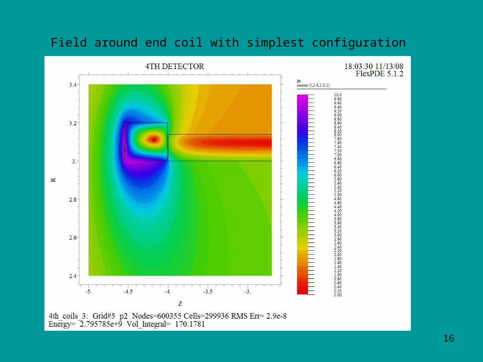
Field around end coil with simplest configuration
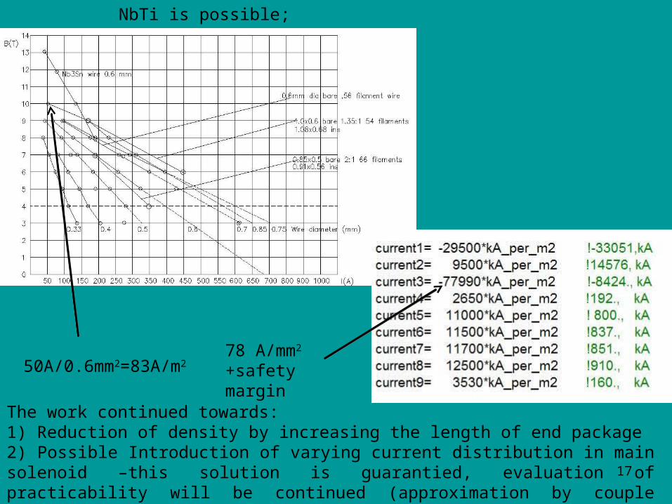
17
50A/0.6mm2=83A/m2 78 A/mm2
+safety margin
NbTi is possible;
The work continued towards:1) Reduction of density by increasing the length of end package 2) Possible Introduction of varying current distribution in main solenoid –this solution is guarantied, evaluation of practicability will be continued (approximation by couple addition sections)
18
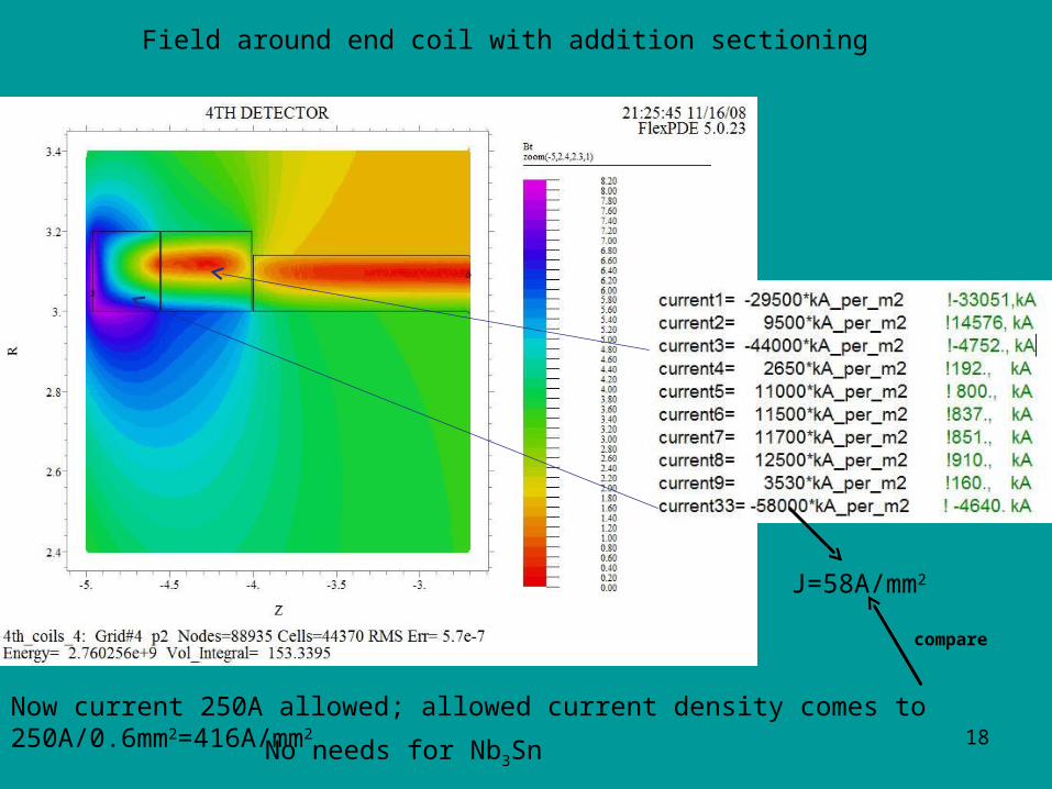
Field around end coil with addition sectioning
Now current 250A allowed; allowed current density comes to 250A/0.6mm2=416A/mm2
J=58A/mm2
compare
No needs for Nb3Sn
19
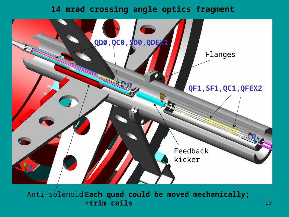
QD0,QC0,SD0,QDEX1
QF1,SF1,QC1,QFEX2
14 mrad crossing angle optics fragment
Flanges
Feedback kicker
Anti-solenoid Each quad could be moved mechanically;+trim coils
20
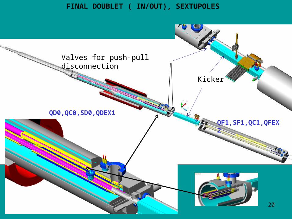
Valves for push-pull disconnection
FINAL DOUBLET ( IN/OUT), SEXTUPOLES
QF1,SF1,QC1,QFEX2
QD0,QC0,SD0,QDEX1
Kicker
21
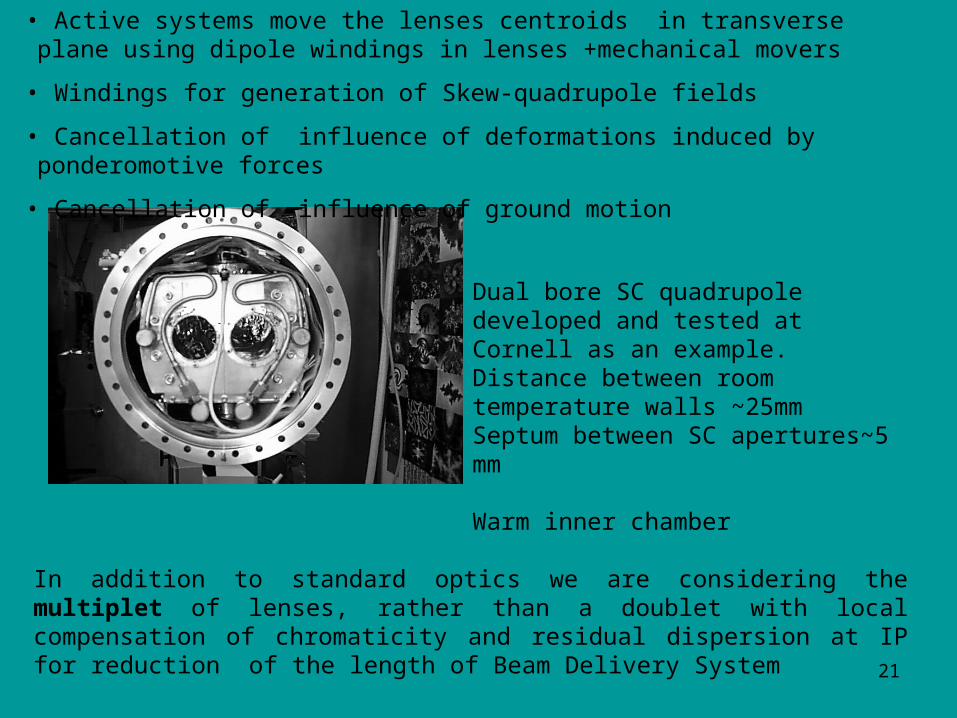
In addition to standard optics we are considering the multiplet of lenses, rather than a doublet with local compensation of chromaticity and residual dispersion at IP for reduction of the length of Beam Delivery System
• Active systems move the lenses centroids in transverse plane using dipole windings in lenses +mechanical movers
• Windings for generation of Skew-quadrupole fields
• Cancellation of influence of deformations induced by ponderomotive forces
• Cancellation of influence of ground motion
Dual bore SC quadrupole developed and tested at Cornell as an example. Distance between room temperature walls ~25mmSeptum between SC apertures~5 mm
Warm inner chamber
22
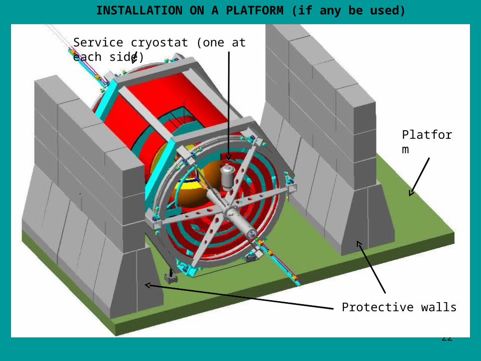
Platform
Service cryostat (one at each side)
INSTALLATION ON A PLATFORM (if any be used)
Protective walls

3D SKETCH OF THE CAVE
Loading detector. Mostly of equipment attached to the frame already (solenoids, muon spectrometer parts, calorimeters…)
Tunnel shields at the cave entrances (Pacmans) not shown (next slide)
Shaft diameter ~16m
~120m
~25m
~40m
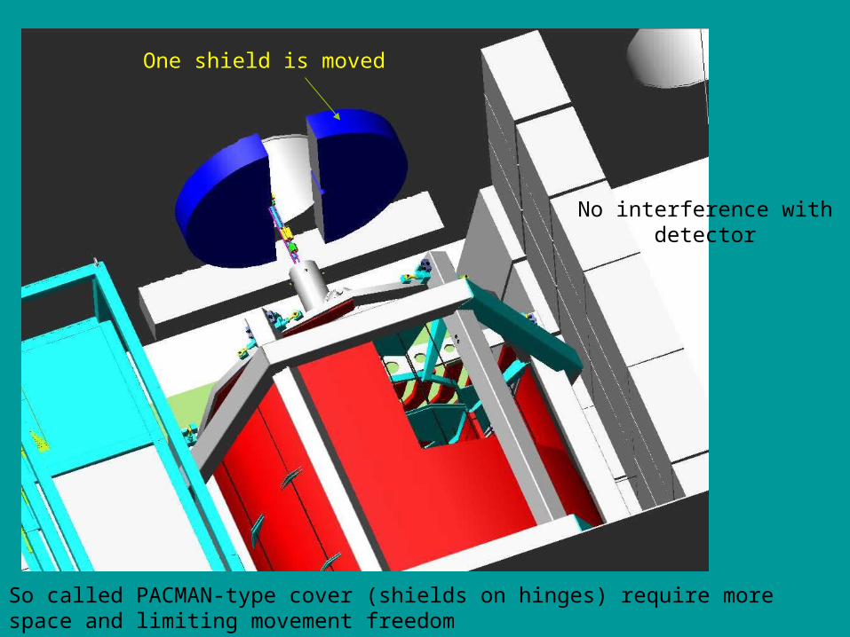
One shield is moved
No interference with detector
So called PACMAN-type cover (shields on hinges) require more space and limiting movement freedom
25
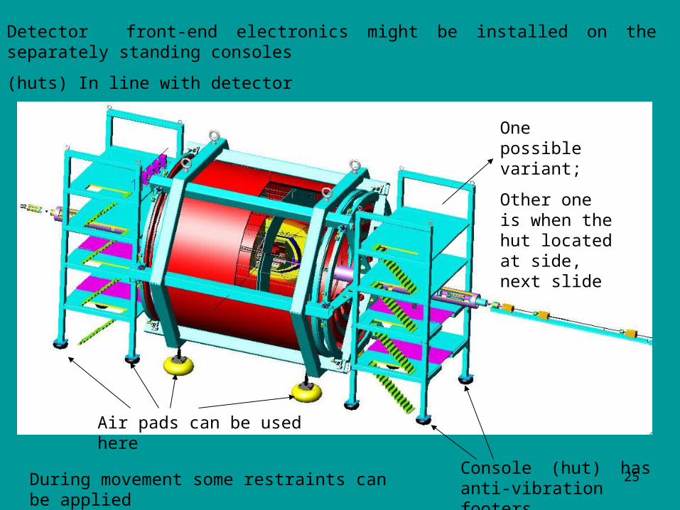
Detector front-end electronics might be installed on the separately standing consoles
(huts) In line with detector
Console (hut) has anti-vibration footers.
Disconnection for push-pull detector exchange
Air pads can be used here
During movement some restraints can be applied
One possible variant;
Other one is when the hut located at side, next slide
26
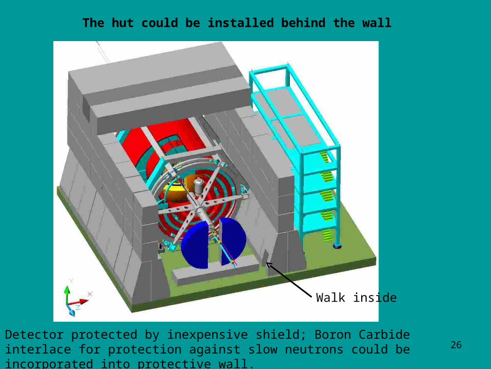
The hut could be installed behind the wall
Walk inside
Detector protected by inexpensive shield; Boron Carbide interlace for protection against slow neutrons could be incorporated into protective wall.
27
• All MDI questions could be answered;
• 4-th concept detector can easy accommodate any beam optics;
• It can be easily installed in cave as it has no heavy Iron;
• 4th-concept allows easy motion into cave for push-pull operation;
• Elements of FF optics mounted on detector frame allow better protection against ground motion; active system against vibrations;
• Field can be made homogeneous to satisfy Tracking System request; measured accurately as there is no interference from Iron (10-4);
• Easy upgrade for gamma-gamma if necessary ;
• Modular concept of 4-th detector allows easy exchange of different equipment, such as TPC, Vertex detector, sections of calorimeter, gamma-gamma hardware and Newest Tracking System;
• Current density could be reduced by sectioning to allow NbTi wire by end coil sectioning;
• Engineering stage for coil design must be continued toward practical tests of concept.
CONCLUSIONS
Backup slides
28
29
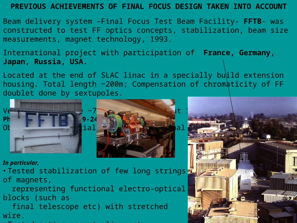
PREVIOUS ACHIEVEMENTS OF FINAL FOCUS DESIGN TAKEN INTO ACCOUNT
Beam delivery system –Final Focus Test Beam Facility- FFTB- was constructed to test FF optics concepts, stabilization, beam size measurements, magnet technology, 1993.
International project with participation of France, Germany, Japan, Russia, USA.
Located at the end of SLAC linac in a specially build extension housing. Total length ~200m; Compensation of chromaticity of FF doublet done by sextupoles.
Vertical beam size ~70nm was measured at IP – Phys.Rev.Lett.74:2479-2482,1995Obtained substantial experience in Final Focus design
In particular,
• Tested stabilization of few long strings of magnets, representing functional electro-optical blocks (such as final telescope etc) with stretched wire. • Tested active magnet alignment. • Introduced and tested ballistic method for FF alignment • Tested new-type beam size monitor for nm scale

30
Recent addition – toroid between TPC and calorimeter for increase of momentum resolution for particles with small angle. TPC will come to r=20cm radially and extend to z=1.7m axially including the readout end plates. Concept not finished yet
TPC
Vertex
Fiber hadronic calorimeter
Fiber hadronic calorimeter
Crystal EM calorimeter
Fiber hadronic calorimeter
31
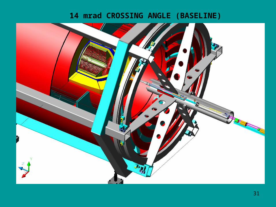
14 mrad CROSSING ANGLE (BASELINE)

32
WALL OF COILSAxis-symmetrical system of coils restricts propagation of field out of detector
All side coils are room-temperature ones; have ~same current density; water cooled
Current density: 1; 8; 4.2; 3.3; 3.7; 1.7 A/mm2
Field outside detector can be zeroed to any level by proper current distribution; Coils can be fixed easily at the end plates
Center of detector
Forces :1.75; 102; 131; 135; 111; 10 tons
(Effective CMS Current density ~14.2 A/mm2 (with stabilizer area). meanwhile typical practical current density in directly cooled SC wire is 1500A/mm2 for 3.5 T field--- lot to think about)
z
33
4th-concept allows easy installation into cave as it has no heavy Iron;
Elements of FF optics mounted on detector frame allowing better protection against ground motion;
Field can be made homogeneous to satisfy TPC request and measured accurately as there is no interference from Iron (10-4);
Measures against vibrations force to locate front end electronics in a separate hut installed on vibration-isolative footers;
Modular concept of 4-th detector allows easy exchange of different equipment, such as TPC, vertex detector, sections of calorimeter, gamma-gamma collisions etc.;
Detector could be manufactured at lowest cost;
Detector can be reassembled quickly to take benefits from different energy of colliding e+e- beams;Detector allows relatively quick flip of magnetic field orientation for calibration of asymmetry; this is beneficial for collisions with polarized beams.
4-th concept easily accommodates 14 mrad optics.
Head on collision scheme delivers undoubted benefits for HEP and for the beam optics. Directional kicker with TEM wave can be used here.
34
Different energy of colliding beams. It is natural to keep such possibility for ILC. Here all background products generated off-center in contrast with asymmetric B-factory.
ILC accelerating structure is a standing wave type; it allows acceleration in both directions. One can consider the possibility to work at double energy with a stationary target. For this action, the beam accelerated in the first linac is redirected through IP into another one. The phasing could be arranged; the optics needs to be tuned.
Zero crossing angle. Nonzero angle initiated by NLC/JLC type machines. Crossing angle vas not required for TESLA, VLEPP. Zero angles give advantages in optics, preventing from SR in magnetic field of detector and degradation of luminosity. So we think, that this option must be kept in detector design as alternative.
Monochromatization –the ability to arrange collision at IP in such a way, that low energy particles from the first beam collide with the higher energy ones in the opposing beam. This idea was considered for circular machines a long time ago. For a single pass system, as the ILC is, realization of such program becomes much easier procedure. Despite significant SR energy spread generated during collision, this might be important for measurements at narrow resonances, including low energy option (Giga-Z).
Work with nonzero dispersion at IP. This might be useful for monochromatization and to simplify the FF optics.
Adiabatic focusing at IP. Focusing arranged with multiplet of quadrupoles, rather than a doublet so that the strength of the lenses changes slowly from lens to lens.
Peculiarity for registering of collisions with both polarized beams. Registration of back-forward asymmetries of secondary products is the main task for operation with polarized particles. This question requires special attention. 4-th magnet allows easy swap polarity.
35
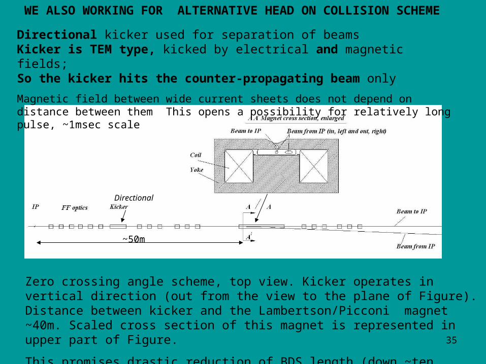
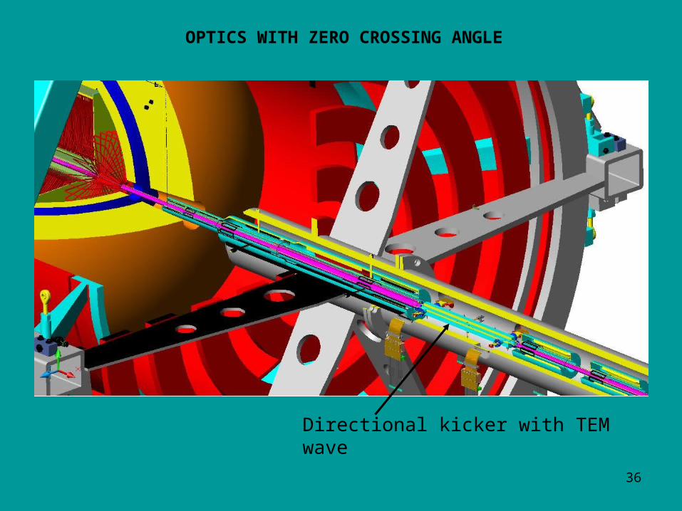
Zero crossing angle scheme, top view. Kicker operates in vertical direction (out from the view to the plane of Figure). Distance between kicker and the Lambertson/Picconi magnet ~40m. Scaled cross section of this magnet is represented in upper part of Figure.
This promises drastic reduction of BDS length (down ~ten times)
~50m
Directional kicker used for separation of beams Kicker is TEM type, kicked by electrical and magnetic fields;So the kicker hits the counter-propagating beam only
Magnetic field between wide current sheets does not depend on distance between them This opens a possibility for relatively long pulse, ~1msec scale
WE ALSO WORKING FOR ALTERNATIVE HEAD ON COLLISION SCHEME
Directional
36
OPTICS WITH ZERO CROSSING ANGLE
Directional kicker with TEM wave
37
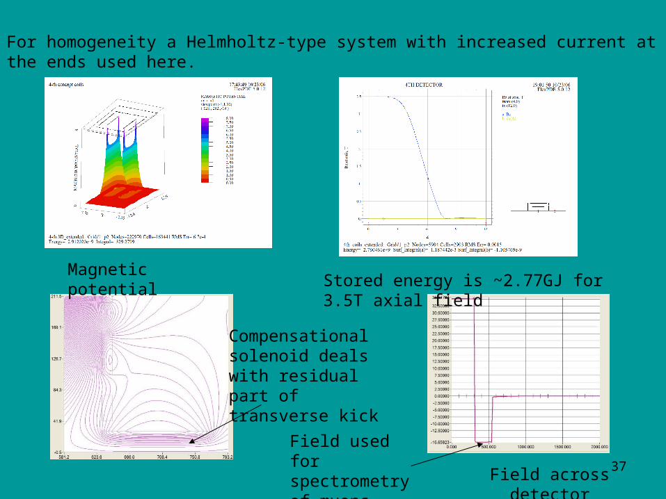
For homogeneity a Helmholtz-type system with increased current at the ends used here.
Stored energy is ~2.77GJ for 3.5T axial fieldMagnetic potential
Compensational solenoid deals with residual part of transverse kick
Field across detector
Field used for spectrometry of muons
38
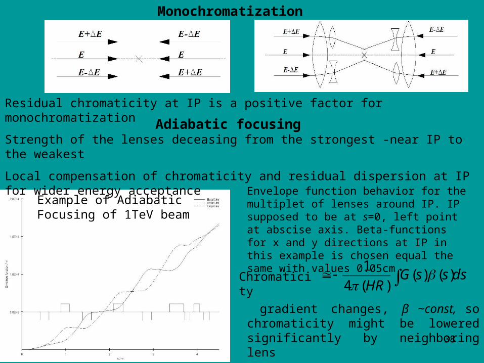
Envelope function behavior for the multiplet of lenses around IP. IP supposed to be at s=0, left point at abscise axis. Beta-functions for x and y directions at IP in this example is chosen equal the same with values 0.05cm.
Monochromatization
Adiabatic focusing
Example of Adiabatic Focusing of 1TeV beam
Strength of the lenses deceasing from the strongest -near IP to the weakest
Local compensation of chromaticity and residual dispersion at IP for wider energy acceptance
Residual chromaticity at IP is a positive factor for monochromatization
dsssGHR )()()(4
1
gradient changes, β ~const, so chromaticity might be lowered significantly by neighboring lens
Chromaticity
39
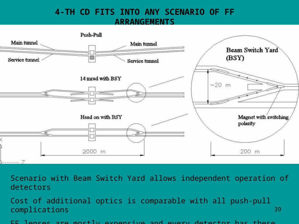
4-TH CD FITS INTO ANY SCENARIO OF FF ARRANGEMENTS
Scenario with Beam Switch Yard allows independent operation of detectors
Cost of additional optics is comparable with all push-pull complications
FF lenses are mostly expensive and every detector has these lenses already
4th CD can be easily fit into this scenario
40
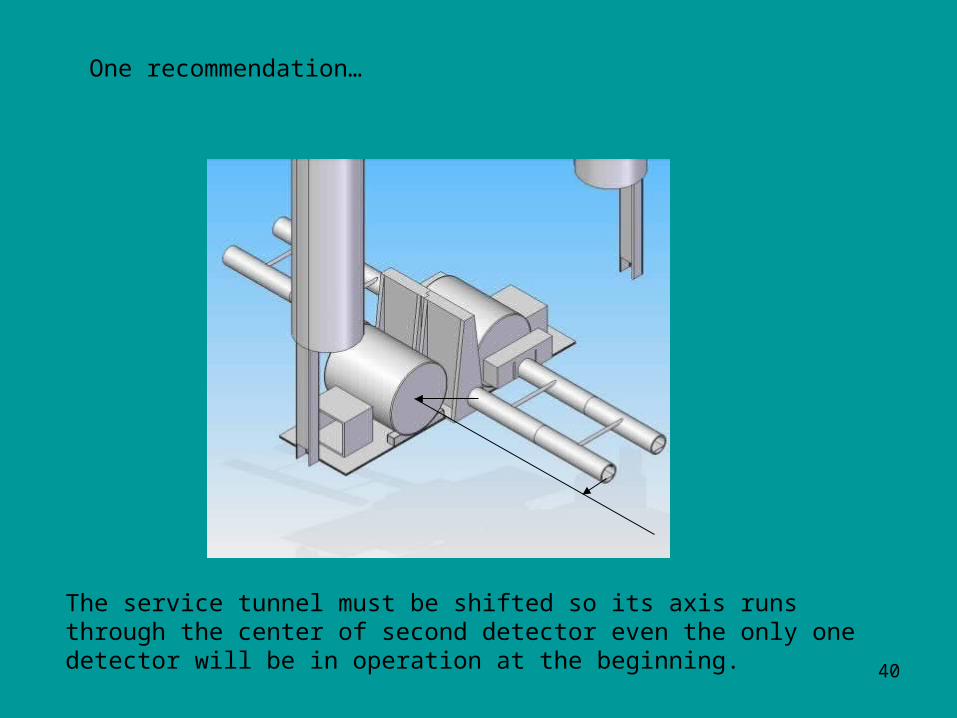
One recommendation…
The service tunnel must be shifted so its axis runs through the center of second detector even the only one detector will be in operation at the beginning.