Embed Size (px)
Citation preview
ENVIRONMENTAL STATEMENT
The Proposed Development & Alternatives
P17-0534_04_ProposedDev&AltsRevB_260318 Bio Plant, Deeside
4 THE PROPOSED DEVELOPMENT & ALTERNATIVES
4.1 INTRODUCTION
4.1.1 This chapter of the Environmental Statement (ES) sets out the description of the
Proposed Development and its construction, and identifies the main alternatives to
the Proposed Development that have been considered and the reasons why these
were rejected.
4.2 THE PROPOSED DEVELOPMENT
4.2.1 The planning application seeks detailed planning consent for a municipal solid waste
(MSW) and commercial and industrial waste (C & I) recycling and recovery plant on
land at Deeside Industrial Estate, Flintshire Enterprise Zone. More specifically this
includes hydro mechanical separation and preparation and multi stage anaerobic
digestion waste recycling plant.
4.2.2 The Proposed Development is described in more detail throughout this chapter,
however comprises the following principal elements:
• Processing unit where the hydro-mechanical separation and preparation
occurs. This includes a waste reception hall with ground level tipping area,
sorting hall, with associated equipment for separation and processing. The
waste areas will be housed under a negative pressure with fast acting doors.
The building also includes a Refused Derived Fuel (RDF) hall, control room,
electrical room and workers facilities;
• Anaerobic Digestion tank farm, including digester tanks, acetogenic tanks,
methanogenic tank and a balancing tank, where the biological multi stage
anaerobic digestion processing occurs;
• Biogas holder balloon of approximately 1000m3;
• Waste water treatment area and dewatering area;
• Generator;
• Bio-filter;
• Internal access road with pedestrian walkways and passing places;
• Car parking area, bin storage area and maintenance depot/fuel and oil
storage;
• Two way weighbridge for trucks delivering waste or recyclables in and out;
• Washing station for trucks prior exiting the site;
• Access from Weighbridge Road; and
• Ancillary infrastructure (including utility services, drainage, retaining wall,
internal roads and related lighting) and associated earthworks.
4.2.3 In accordance with Environmental Impact Assessment (EIA) case law, the EIA has
been carried out with regards to a range of fixed development parameters to
enable a robust assessment of the proposals to be completed.
4.2.4 The Proposed Development which has been the subject of this EIA is shown within
Figure 4.1. This plan has been assessed against baseline conditions within each
environmental discipline. Figures 4.2, 4.3 and 4.4 also provide indicative
elevations and visuals of the main structures proposed on the site.
ENVIRONMENTAL STATEMENT
The Proposed Development & Alternatives
Bio Plant, Deeside P17-0534_04_ProposedDev&AltsRevB_260318
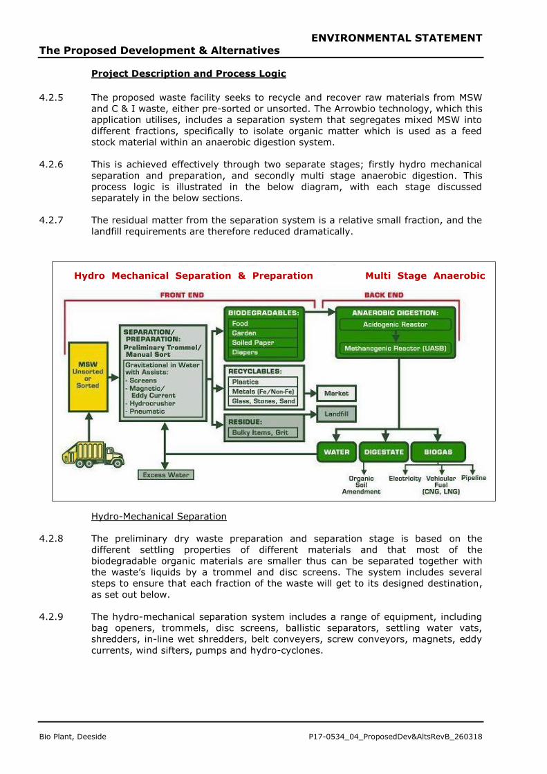
Project Description and Process Logic
4.2.5 The proposed waste facility seeks to recycle and recover raw materials from MSW
and C & I waste, either pre-sorted or unsorted. The Arrowbio technology, which this
application utilises, includes a separation system that segregates mixed MSW into
different fractions, specifically to isolate organic matter which is used as a feed
stock material within an anaerobic digestion system.
4.2.6 This is achieved effectively through two separate stages; firstly hydro mechanical
separation and preparation, and secondly multi stage anaerobic digestion. This
process logic is illustrated in the below diagram, with each stage discussed
separately in the below sections.
4.2.7 The residual matter from the separation system is a relative small fraction, and the
landfill requirements are therefore reduced dramatically.
Hydro-Mechanical Separation
4.2.8 The preliminary dry waste preparation and separation stage is based on the
different settling properties of different materials and that most of the
biodegradable organic materials are smaller thus can be separated together with
the waste’s liquids by a trommel and disc screens. The system includes several
steps to ensure that each fraction of the waste will get to its designed destination,
as set out below.
4.2.9 The hydro-mechanical separation system includes a range of equipment, including
bag openers, trommels, disc screens, ballistic separators, settling water vats,
shredders, in-line wet shredders, belt conveyers, screw conveyors, magnets, eddy
currents, wind sifters, pumps and hydro-cyclones.
Hydro Mechanical Separation & Preparation Multi Stage Anaerobic
Digestion
ENVIRONMENTAL STATEMENT
The Proposed Development & Alternatives
P17-0534_04_ProposedDev&AltsRevB_260318 Bio Plant, Deeside
4.2.10 The main separation steps are as follows:
• Mixed MSW is fed into a bag opener. Then into a trommel with 150mm &
300mm hole size;
• The oversize (>300mm) materials will continue for manual picking
(cardboard, metals, large HDPE) and a wind sifter for recovering light
fraction;
• The midsize (150-300mm) will continue to a ballistic separator for dividing
2D and 3D materials.
• 3D materials will be sorted manually/automatically to recyclables as metals,
PET, HDPE depending on the market. Wind sifter at the end of the line.
• 2D materials will be sorted manually/automatically for paper/cardboards and
wind sifter at the end of the line.
• The undersize (<150mm) with 95% of the organic fraction will continue to a
disc screen of 60/80mm.
• Undersize (<60/80mm) is conveyed under an over belt magnet (for ferrous
metals) and then through a liquid screen (2.5mm slots) into the settling vat,
that divides to 3 streams a) heavy fractions e.g. glass and stones; b) light
fraction e.g. plastics and fibres; and c) organic fraction that will be pumped to
the biological treatment area (AD tanks). See below section for this separate
process
4.2.11 The materials from each of the above separation steps are then dealt with as
follows:
• Oversize (>60/80) passes a magnet and an eddy current to separate the
ferrous and none ferrous metals; manual picking conveyor for recyclables;
wind sifter; then shredded and screened with another disc screen.
• The undersize will go to a settling vat and then will be pumped to the
biological area.
• Stream to AD tanks all organic and other materials that are pumped to the
AD tanks will be chopped to the size of 10mm with inline shredders.
• Recyclables such as paper and plastics will be accumulated in bunkers and
will be conveyed to a baler for optimizing shipments to the customers.
• Glass – whole bottles will be picked manually into collection bins. Broken
glass that will come out from the settling vats will be separated with X-ray
fluorescence or Near-Infrared spectroscopy.
• Sand removal most of the sand will fall with the under size of the liquid
screen (2.5mm), and will be removed from the process by hydro-cyclones.
• Wet residue from the settling vats or the biological area will pass a screw
press prior going to landfill offsite, the pressed liquids will be recycled back in
to the process.
Anaerobic Digestion and Wastewater Treatment
4.2.12 The organic material isolated in the above process is then used as a feed stock
material within the multi stage anaerobic digestion (AD) system, which takes place
in an advanced high efficiency reactors where environmental conditions can be
controlled to maximize microbe activity, gas production and waste decomposition
rates.
4.2.13 The anaerobic process occurs in two phases; firstly, acetogenic micro-organisms
breakdown complex materials into smaller molecules of organic acids (this includes
both low solid and high solid feed streams as generated by the earlier separation
technology); and secondly, methanogenic micro-organisms breakdown the organic
acids to form biogas. Further information on the processes can be found within
Appendix 4.1.
ENVIRONMENTAL STATEMENT
The Proposed Development & Alternatives
Bio Plant, Deeside P17-0534_04_ProposedDev&AltsRevB_260318
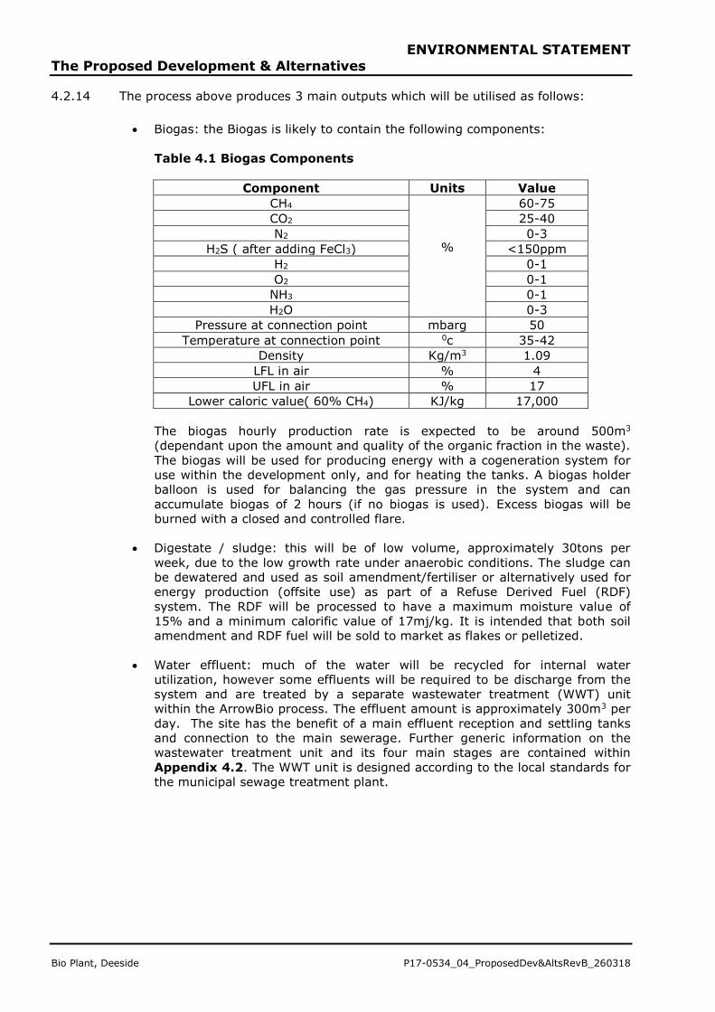
4.2.14 The process above produces 3 main outputs which will be utilised as follows:
• Biogas: the Biogas is likely to contain the following components:
Table 4.1 Biogas Components
Component Units Value
CH4
%
60-75
CO2 25-40
N2 0-3
H2S ( after adding FeCl3) <150ppm
H2 0-1
O2 0-1
NH3 0-1
H2O 0-3
Pressure at connection point mbarg 50
Temperature at connection point 0c 35-42
Density Kg/m3 1.09
LFL in air % 4
UFL in air % 17
Lower caloric value( 60% CH4) KJ/kg 17,000
The biogas hourly production rate is expected to be around 500m3
(dependant upon the amount and quality of the organic fraction in the waste).
The biogas will be used for producing energy with a cogeneration system for
use within the development only, and for heating the tanks. A biogas holder
balloon is used for balancing the gas pressure in the system and can
accumulate biogas of 2 hours (if no biogas is used). Excess biogas will be
burned with a closed and controlled flare.
• Digestate / sludge: this will be of low volume, approximately 30tons per
week, due to the low growth rate under anaerobic conditions. The sludge can
be dewatered and used as soil amendment/fertiliser or alternatively used for
energy production (offsite use) as part of a Refuse Derived Fuel (RDF)
system. The RDF will be processed to have a maximum moisture value of
15% and a minimum calorific value of 17mj/kg. It is intended that both soil
amendment and RDF fuel will be sold to market as flakes or pelletized.
• Water effluent: much of the water will be recycled for internal water
utilization, however some effluents will be required to be discharge from the
system and are treated by a separate wastewater treatment (WWT) unit
within the ArrowBio process. The effluent amount is approximately 300m3 per
day. The site has the benefit of a main effluent reception and settling tanks
and connection to the main sewerage. Further generic information on the
wastewater treatment unit and its four main stages are contained within
Appendix 4.2. The WWT unit is designed according to the local standards for
the municipal sewage treatment plant.
ENVIRONMENTAL STATEMENT
The Proposed Development & Alternatives
P17-0534_04_ProposedDev&AltsRevB_260318 Bio Plant, Deeside
Layout
4.2.15 The layout seeking permission, and that which has been assessed within this ES, is
illustrated on Figure 4.1. Figure 4.2 also provides indicative elevations of the
main structures on site.
4.2.16 The layout proposes to use the existing access to the site off Weighbridge Road in
the site’s south western corner. The layout beyond this point has been driven by
the operational needs of the facility and has been heavily determined by the
proposed vehicular movement on the site.
4.2.17 Once entering the site, the road leads to a car park with approximately 34 spaces
for staff; a visitors and disabled car park is located further into the site adjacent to
the entrance to the main processing building. The main processing building, where
the mechanical separation and preparation occurs (as discussed earlier in this
chapter), is situated to the eastern area of the site allowing for refuse vehicles and
HGVs to pass through the necessary weighbridges prior to manoeuvring into the
building, where they will either deposit the MSW at the waste reception hall (within
the main building), or collect RDF or recyclables (within the main building) or
containers for landfill. The internal areas of the plant will operate under a negative
air pressure and have fast acting automatic doors.
4.2.18 The input is expected to be 600 MT of waste per day or 182,000 MT per year, with
the majority of the waste expected to be domestic household MSW type, along with
commercial and industrial waste and food and organic waste in general. The source
of the waste is likely to come from some of the local county councils (assuming c.
50 mile radius initially) in the form of local waste trucks direct from the residents
homes, thereby diverting away from landfill.
4.2.19 The length of the technical processes utilised necessitates a north/south orientation
of the processing building on the site with the tank farm at the northern end of the
building. In addition to the mechanical separation and preparation, the building will
also include office and welfare facilities at first floor level, and the Refused Derived
Fuel (RDF) storage hall. The main building extends to c. 122m in length, excluding
canopies (c. 145m including canopies), and varies in width from c. 53.75m at the
southern end to 34.6m at the northern end. The maximum height of the building is
20.59m, with the gross internal floor area (including first floor office/ancillary
accommodation) totalling 7,370 m2.
4.2.20 The internal road is designed to ensure an accessible ‘loop’ can be made by the
goods vehicles, which includes, on exiting the site, the vehicles to pass through a
wheel washing facility and the (2-way) weighbridge once more.
4.2.21 The anaerobic digestion area is located to the north of the main building, in the
north east corner of this site. This includes a number of tanks for each stage of the
process, in addition to the Waste Water Treatment dewatering system and
laboratory. The whole area has a sunken bund. The proposed tanks and types are
provided in Table 4.2 below:
ENVIRONMENTAL STATEMENT
The Proposed Development & Alternatives
Bio Plant, Deeside P17-0534_04_ProposedDev&AltsRevB_260318
Table 4.2 Tank Farm Schedule
Name Maximum
Diameter/Height
(m)
Quantity Matter in tank
Acetogenic 9/12 3 2.5mm<X<30mm organic
with some plastics
Digester 10/12 3 0.75mm<X<2.5mm
Fine organic with small
plastic chips
Methanogenic 16/15 1 X<0.75mm organic liquid
Balance 10.5/11.5 1 Treated waste water for
separation area
SBR 6/7 1 Waste water after sludge
dewatering
Settling 6/6 1 Aerated waste water
Sampling 5/5 1 Treated waste water
before sewage
Biogas holder 12.5 (D of sphere) 1 Biogas (potential to hold
1000m3)
2.5mm drum
screen
1.8/4 (D/length) 3 Receiving from Acetogenic
0.75mm drum
screen
1.8/4 (D/length) 3 Receiving from Digester
and undersize of 2.5
screen
Screw press 0.6/1/1.5 W/H/L 3 Sludge for dewatering
DAF TBD (according to
quality of organic
waste)
1 Waste water after sludge
dewatering
4.2.22 In addition to the above, the facility also proposes a maintenance depot/fuel and oil
store in the south eastern corner of the site, in addition to a bin storage area
located on the internal road loop to the west of the site. A biogas generator which
will produce electricity to run the plant is also proposed to the east of the main
building, alongside a bio-filter. The location and sizes of these are depicted on
Figure 4.1.
Anticipated Vehicle Movements
4.2.23 Based on the above proposals, the following approximate vehicle movements are
assumed, and have been used accordingly in relevant environmental assessments.
Table 4.3 Approximate Vehicle Movements
Vehicle Categories Movements
RCV 80
Residue Trucks 20
Recyclable Trucks 2
RDF Trucks 4
Employees/Deliveries 40
Total 146
Daily Movements 292
ENVIRONMENTAL STATEMENT
The Proposed Development & Alternatives
P17-0534_04_ProposedDev&AltsRevB_260318 Bio Plant, Deeside
Hours of Operation and Staff Levels
4.2.24 The core operational hours are assumed to be from 6am to 8pm 5 days a week,
with deliveries from 6am to 4pm 5 days a week. The biological area will operate 24
hours a day, 7 days a week, to some degree. After regular shift hours it switches to
night mode and only self-circulating systems work.
4.2.25 The process will be fully automated from a central control room via a SCADA
system with remote access, alarms and telemetry.
4.2.26 The plant is likely to employ (in the order of) the following number of staff:
General Manager …………………..………… 1
Operation manager ………………..……….. 1
Control operator ……………………..………. 2
Maintenance ……………………………..……. 5
Machine/forklift/crane operators……… 6
Biological area operator/laboratory ... 2
Regular workers ……………………………. 18
Weighbridge ……………………………………. 1
Other part time ………………………. 4
Total employees……………………… 40
General Maintenance, Management Systems and Monitoring
4.2.27 General maintenance will be done during operation hours where possible and will
include weekly cleaning and inspection. Periodically it may be necessary to
grease/oil/change parts according to supplier's demand and according to safety
regulations.
4.2.28 Plant surfacing will be subject to daily cleaning walkway and vehicle drive areas
with high pressure water, with mechanical sweepers and manually.
Safety and Security Elements
4.2.29 Incidents and non-conformances, including spills from conveyors or other
machinery will happen from time to time during operation or maintenance; all
designated pedestrian areas will be marked and covered if needed.
4.2.30 All ‘wet’ areas are bunded and surrounded with troughs to ensure that any leaked
liquid drains back into the system.
4.2.31 The plant is equipped with firefighting equipment and safety outlet doors and signs
according to local regulations, in addition to an in house sprinkler system to help
contain any fire incidents.
4.2.32 All areas with waste will be closed or covered and closed areas will have air
circulation system with mechanical or biological filters.
4.2.33 The site will be monitored with CCTV for process, safety and security purposes. On
site biometrics will be utilised to monitor personnel.
4.2.34 Whilst the biogas that is produced contains a lower level of methane than natural
gas, the same safety regulations will be applied and to avoid explosion/flame while
handling biogas the following precaution must be taken:
ENVIRONMENTAL STATEMENT
The Proposed Development & Alternatives
Bio Plant, Deeside P17-0534_04_ProposedDev&AltsRevB_260318
• 1. Measure the methane content in the biogas. (See LFL/ UFL data)
• 2. No static electricity contact to biogas.
• 3. No smoking is allowed in the tank farm area.
• 4. No sparks, Welding, Electrical circuits or any other ignition factor near
biogas.
• 5. All equipment must be with explosion proof enclosure .
• 6. Avoid breathing the biogas. If needed, use mask with filter.
• 7. The only authorized person regarding handling the biogas / work near the
biogas is a safety expert or other person that is authorized by the safety
expert.
4.3 CONSTRUCTION
Program and Methodology
4.3.1 It is anticipated that construction of the plant is likely to take in the order of 18
months, with the plant being operation in 2020.
4.3.2 It is anticipated that the working hours will be as set out below:
• 08.00 – 18.00 Monday to Friday; and
• 08.00 – 13.00 Saturday
4.3.3 All work outside these hours will be subject to prior agreement, and/or reasonable
notice, with the LPA, who may impose certain restrictions. Night time working will
be restricted to exceptional circumstances.
4.3.4 These working hours will be agreed prior to the commencement of the works and
will be set out in the CMP/CEMP.
4.3.5 In the event of unusual activities or events that can be anticipated, these will be
notified to the Council and to the relevant property owners or occupiers wherever
possible and neighbors, in advance of the activity.
Management of Contracts
4.3.6 Individual contracts (for example for waste removal) will incorporate relevant
requirements in respect of environmental control, based largely on the standard of
‘best environmental practice’ (BEP) as well as statutory requirements. Any sub-
contractors (where used) will be required to demonstrate how they will achieve best
practice, how targets will be met and how potential effects will be minimized. All
sub-contractors will be subject to stringent due diligence audit by the Applicant’s
Financial and Health and Safety departments.
Public Liaison
4.3.7 There will be a designated Construction Liaison Officer who will deal with public and
other complaints and enquiries. This nominated individual will be named at the
Application Site entrance, with a contact number, and will be identified to the
Council prior to the start of site activities, and whenever a change of responsibility
occurs.
Responses to Complaints
4.3.8 Any complaints will be logged on site, where necessary. The procedures will specify
the roles and responsibilities of the Construction Liaison Officer and the Council in
ENVIRONMENTAL STATEMENT
The Proposed Development & Alternatives
P17-0534_04_ProposedDev&AltsRevB_260318 Bio Plant, Deeside
respect of breaches and complaints from the public. The required actions will be
different in each specific case, depending on the operation, equipment or location
or applying additional controls.
Decommissioning
4.3.9 Given the design life of the Proposed Development, demolition and
decommissioning has been scoped out of this EIA.
4.4 ALTERNATIVES
4.4.1 Schedule 4, Paragraph 2, of the EIA Regulations requires that the ES contain:
“A description of the reasonable alternatives (for example in terms of
development design, technology, location, size and scale) studied by the
applicant... and an indication of the main reasons for selecting the chosen
option, including a comparison of the environmental effects”.
4.4.2 The main alternatives to the Proposed Development which the Applicant has
considered include:
• The ‘No Development’ Alternative;
• Alternative Locations for the development;
• Alternative Uses;
• Alternative Designs.
The ‘No Development’ Alternative
4.4.3 The ‘No Development’ Alternative refers to the option of leaving the Application Site
in its current use and physical state.
4.4.4 Currently the site comprises an area of vacant brownfield land, that does not have
any current landuse. The site is also allocated within the Flintshire UDP as an
employment site.
4.4.1 The last former use of the majority of the site was as Shotton Power Station, a 210
megawatt gas-fire combined heat and power (CHP) generating station. The station
ceased generating in June 2012 and a restoration/remediation scheme was
submitted and subsequently completed. The majority of the site therefore
comprises remediated previously developed land, a small parcel of the land to the
north did not form part of the Shotton CHP, and therefore this remains as
undeveloped grassland.
4.4.2 The ‘no development’ scenario would leave the site in this current vacant state, and
would fail to fulfill its UDP designation. A vacant site in this location would not be an
efficient use of previously developed land within an urban industrial area, as
encouraged by planning policy. Furthermore, Flintshire’s UDP has a specific policy
EWP6 – Areas of Search for New Waste Management – the ‘no development’
scenario would therefore not fulfil this policy.
4.4.3 Without development the land would remain under utilised and could attract crime
and antisocial behavior, becoming further derelict should it not be maintained in the
long term.
ENVIRONMENTAL STATEMENT
The Proposed Development & Alternatives
Bio Plant, Deeside P17-0534_04_ProposedDev&AltsRevB_260318
Alternative Locations
4.4.4 The joint employment land study (2015) for Wrexham Council and Flintshire County
Council has been produced to analyse the employment land across both Local
Authorities. The report assesses the supply, need and demand for employment land
and premises (Use Class B) in the local authority areas of Wrexham and Flintshire.
It has been carried out on behalf of Wrexham County Borough Council (WCBC) and
Flintshire County Council (FCC) to provide robust evidence to underpin and inform
the Council’s respective Local Development Plans (LDP) to bring them in line with
the updated requirements of Planning Policy Wales (PPW) and Technical Advice
Note (TAN) 23. It will analyse employment land and premises demand, supply and
need to 2030.
4.4.5 Forecast analysis suggests a net negative land requirement of -19ha over the next
17 years. Again this reflects projected contractions in the manufacturing sector.
However, looking at sectors projected to grow gives a positive requirement of 38.5
ha is required to 2030, or 1.90 ha/year.
4.4.6 The largest sector in Flintshire is manufacturing, with 20,000 jobs – representing
27.4% of total employment. Job numbers in the sector have remained broadly in
the 19,000-20,000 range over the last 5-6 years. The Flintshire Regeneration
Strategy for 2009-20 recognises the importance of manufacturing to the area. It
highlights how the sector, particularly advanced manufacturing, is increasingly a
focus for policy makers because of its significant wealth generating potential.
ENVIRONMENTAL STATEMENT
The Proposed Development & Alternatives
P17-0534_04_ProposedDev&AltsRevB_260318 Bio Plant, Deeside
Document reference: http://www.flintshire.gov.uk/en/PDFFiles/Planning/LDP-evidence-base/Local/Wrexham-and-Flintshire-Employment-Land-Review-Study.pdf
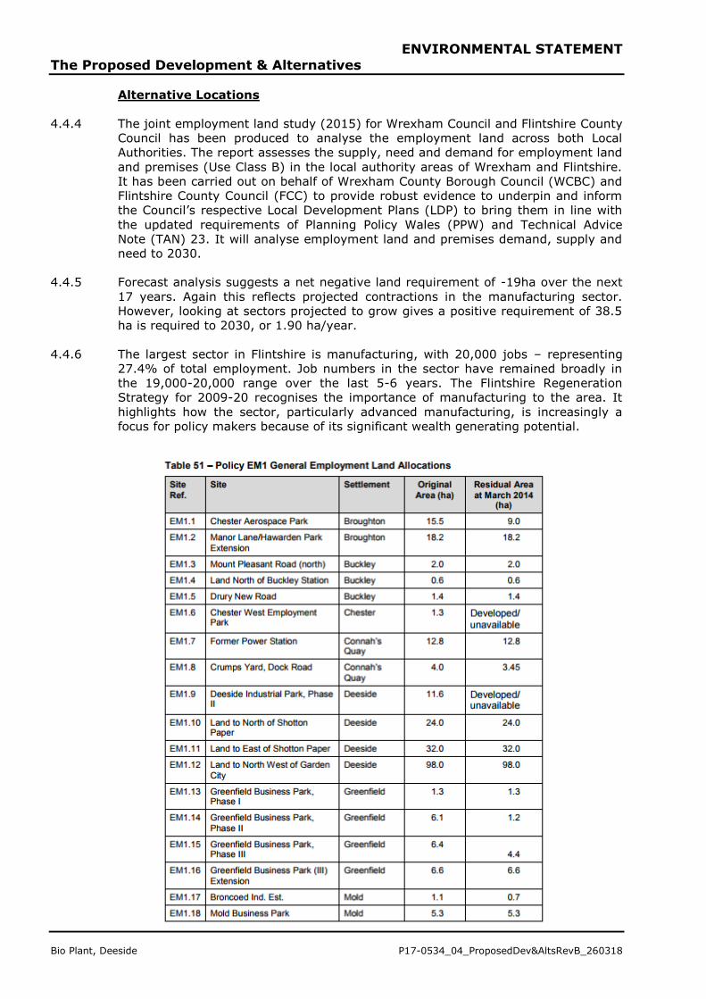
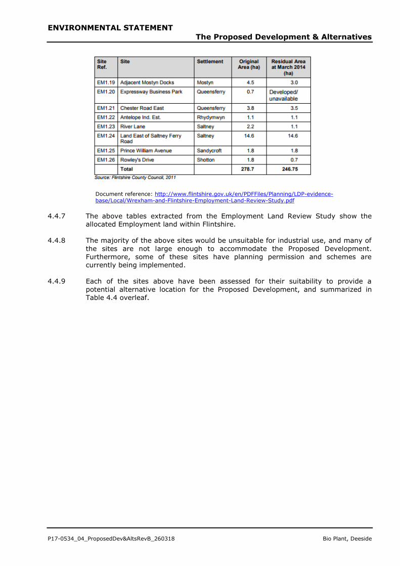
4.4.7 The above tables extracted from the Employment Land Review Study show the
allocated Employment land within Flintshire.
4.4.8 The majority of the above sites would be unsuitable for industrial use, and many of
the sites are not large enough to accommodate the Proposed Development.
Furthermore, some of these sites have planning permission and schemes are
currently being implemented.
4.4.9 Each of the sites above have been assessed for their suitability to provide a
potential alternative location for the Proposed Development, and summarized in
Table 4.4 overleaf.
ENVIRONMENTAL STATEMENT
The Proposed Development & Alternatives
Bio Plant, Deeside P17-0534_04_ProposedDev&AltsRevB_260318
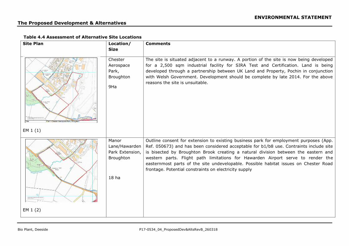
Table 4.4 Assessment of Alternative Site Locations
Site Plan Location/
Size
Comments
EM 1 (1)
Chester
Aerospace
Park,
Broughton
9Ha
The site is situated adjacent to a runway. A portion of the site is now being developed
for a 2,500 sqm industrial facility for SIRA Test and Certification. Land is being
developed through a partnership between UK Land and Property, Pochin in conjunction
with Welsh Government. Development should be complete by late 2014. For the above
reasons the site is unsuitable.
EM 1 (2)
Manor
Lane/Hawarden
Park Extension,
Broughton
18 ha
Outline consent for extension to existing business park for employment purposes (App.
Ref. 050673) and has been considered acceptable for b1/b8 use. Contraints include site
is bisected by Broughton Brook creating a natural division between the eastern and
western parts. Flight path limitations for Hawarden Airport serve to render the
easternmost parts of the site undevelopable. Possible habitat issues on Chester Road
frontage. Potential constraints on electricity supply
ENVIRONMENTAL STATEMENT
The Proposed Development & Alternatives
P17-0534_04_ProposedDev&AltsRevB_260318 Bio Plant, Deeside
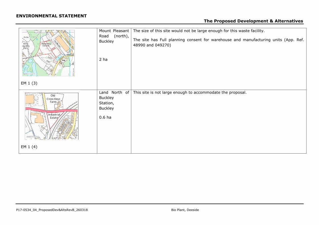
EM 1 (3)
Mount Pleasant
Road (north),
Buckley
2 ha
The size of this site would not be large enough for this waste facility.
The site has Full planning consent for warehouse and manufacturing units (App. Ref.
48990 and 049270)
EM 1 (4)
Land North of
Buckley
Station,
Buckley
0.6 ha
This site is not large enough to accommodate the proposal.
ENVIRONMENTAL STATEMENT
The Proposed Development & Alternatives
Bio Plant, Deeside P17-0534_04_ProposedDev&AltsRevB_260318
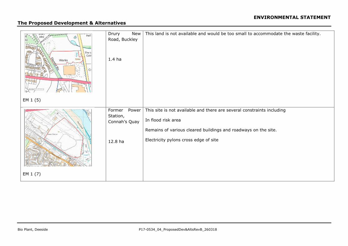
EM 1 (5)
Drury New
Road, Buckley
1.4 ha
This land is not available and would be too small to accommodate the waste facility.
EM 1 (7)
Former Power
Station,
Connah’s Quay
12.8 ha
This site is not available and there are several constraints including
In flood risk area
Remains of various cleared buildings and roadways on the site.
Electricity pylons cross edge of site
ENVIRONMENTAL STATEMENT
The Proposed Development & Alternatives
P17-0534_04_ProposedDev&AltsRevB_260318 Bio Plant, Deeside
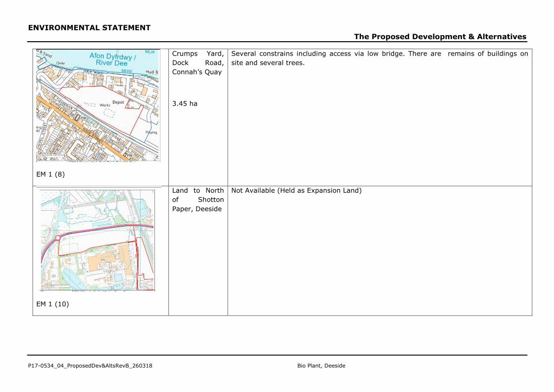
EM 1 (8)
Crumps Yard,
Dock Road,
Connah’s Quay
3.45 ha
Several constrains including access via low bridge. There are remains of buildings on
site and several trees.
EM 1 (10)
Land to North
of Shotton
Paper, Deeside
Not Available (Held as Expansion Land)
ENVIRONMENTAL STATEMENT
The Proposed Development & Alternatives
Bio Plant, Deeside P17-0534_04_ProposedDev&AltsRevB_260318
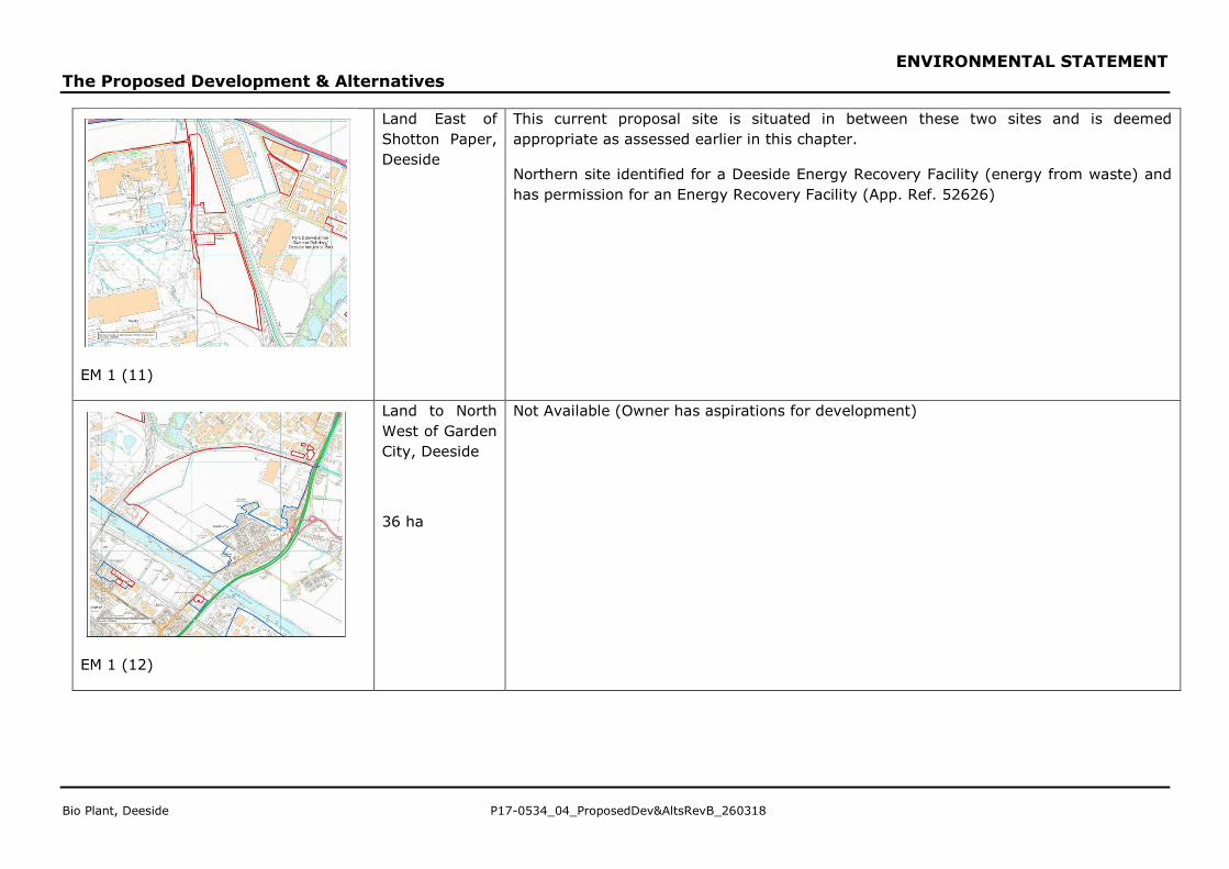
EM 1 (11)
Land East of
Shotton Paper,
Deeside
This current proposal site is situated in between these two sites and is deemed
appropriate as assessed earlier in this chapter.
Northern site identified for a Deeside Energy Recovery Facility (energy from waste) and
has permission for an Energy Recovery Facility (App. Ref. 52626)
EM 1 (12)
Land to North
West of Garden
City, Deeside
36 ha
Not Available (Owner has aspirations for development)
ENVIRONMENTAL STATEMENT
The Proposed Development & Alternatives
P17-0534_04_ProposedDev&AltsRevB_260318 Bio Plant, Deeside
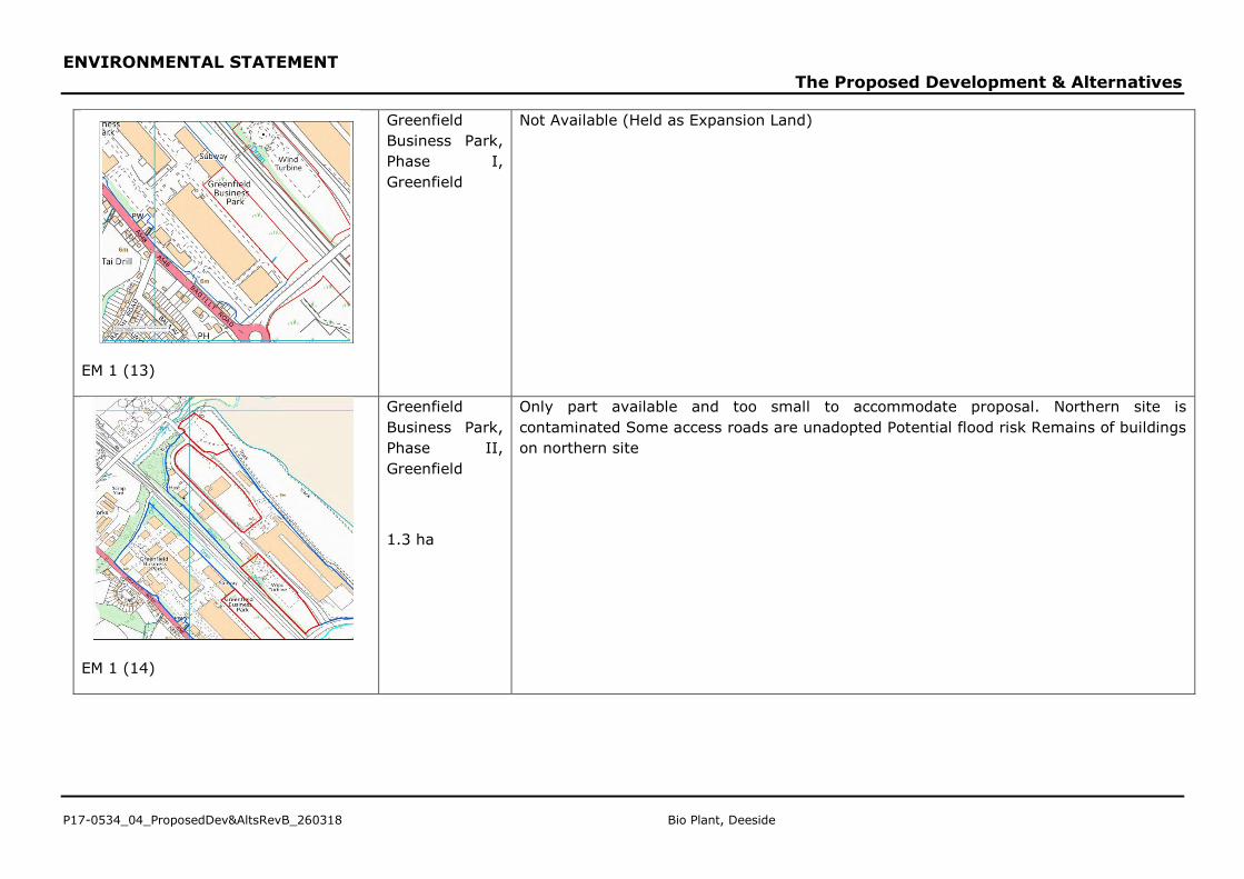
EM 1 (13)
Greenfield
Business Park,
Phase I,
Greenfield
Not Available (Held as Expansion Land)
EM 1 (14)
Greenfield
Business Park,
Phase II,
Greenfield
1.3 ha
Only part available and too small to accommodate proposal. Northern site is
contaminated Some access roads are unadopted Potential flood risk Remains of buildings
on northern site
ENVIRONMENTAL STATEMENT
The Proposed Development & Alternatives
Bio Plant, Deeside P17-0534_04_ProposedDev&AltsRevB_260318
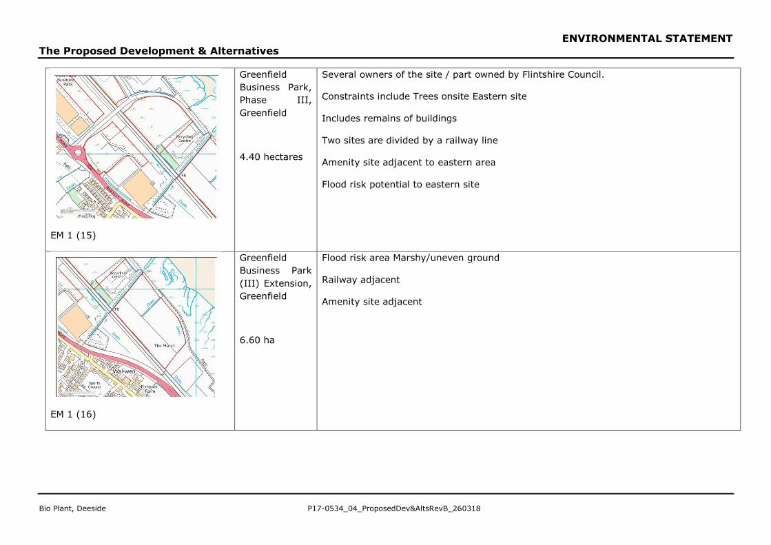
EM 1 (15)
Greenfield
Business Park,
Phase III,
Greenfield
4.40 hectares
Several owners of the site / part owned by Flintshire Council.
Constraints include Trees onsite Eastern site
Includes remains of buildings
Two sites are divided by a railway line
Amenity site adjacent to eastern area
Flood risk potential to eastern site
EM 1 (16)
Greenfield
Business Park
(III) Extension,
Greenfield
6.60 ha
Flood risk area Marshy/uneven ground
Railway adjacent
Amenity site adjacent
ENVIRONMENTAL STATEMENT
The Proposed Development & Alternatives
P17-0534_04_ProposedDev&AltsRevB_260318 Bio Plant, Deeside
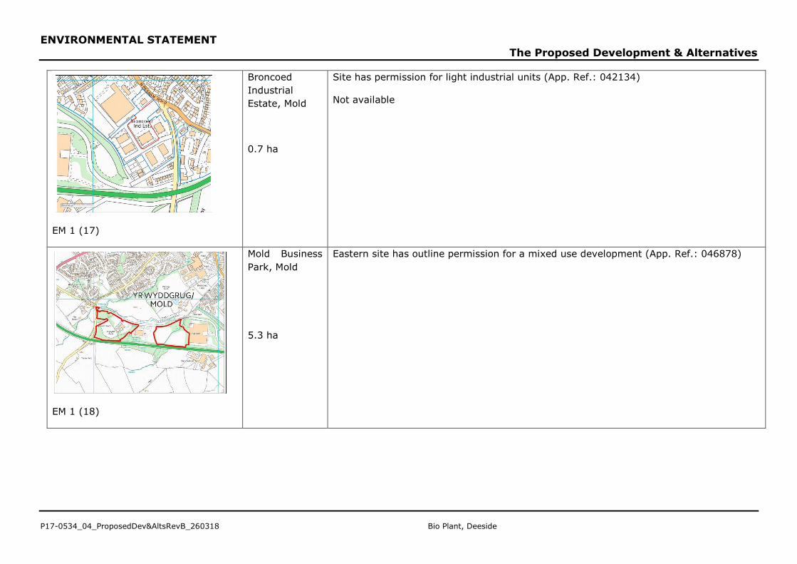
EM 1 (17)
Broncoed
Industrial
Estate, Mold
0.7 ha
Site has permission for light industrial units (App. Ref.: 042134)
Not available
EM 1 (18)
Mold Business
Park, Mold
5.3 ha
Eastern site has outline permission for a mixed use development (App. Ref.: 046878)
ENVIRONMENTAL STATEMENT
The Proposed Development & Alternatives
Bio Plant, Deeside P17-0534_04_ProposedDev&AltsRevB_260318
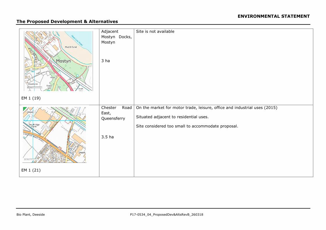
EM 1 (19)
Adjacent
Mostyn Docks,
Mostyn
3 ha
Site is not available
EM 1 (21)
Chester Road
East,
Queensferry
3.5 ha
On the market for motor trade, leisure, office and industrial uses (2015)
Situated adjacent to residential uses.
Site considered too small to accommodate proposal.
ENVIRONMENTAL STATEMENT
The Proposed Development & Alternatives
P17-0534_04_ProposedDev&AltsRevB_260318 Bio Plant, Deeside
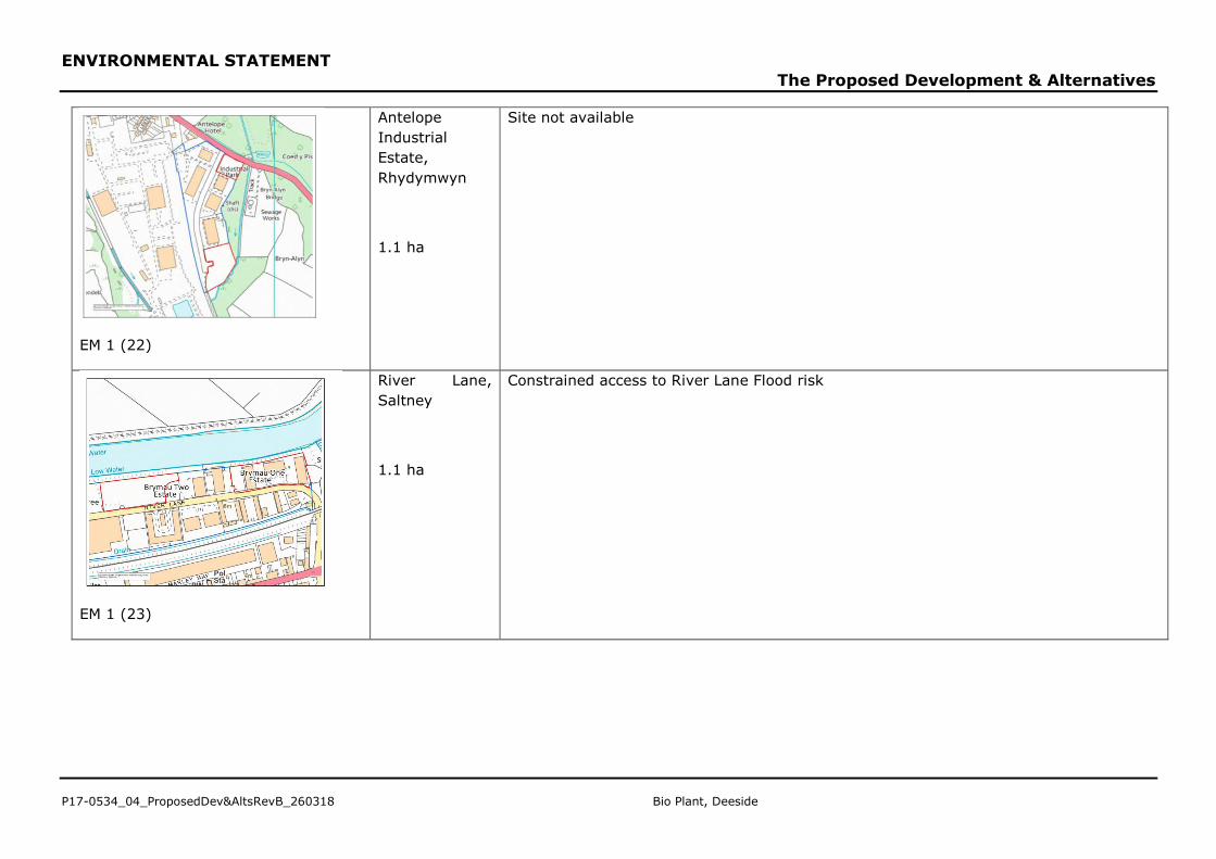
EM 1 (22)
Antelope
Industrial
Estate,
Rhydymwyn
1.1 ha
Site not available
EM 1 (23)
River Lane,
Saltney
1.1 ha
Constrained access to River Lane Flood risk
ENVIRONMENTAL STATEMENT
The Proposed Development & Alternatives
Bio Plant, Deeside P17-0534_04_ProposedDev&AltsRevB_260318
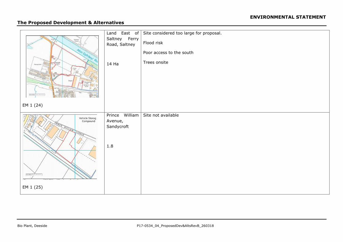
EM 1 (24)
Land East of
Saltney Ferry
Road, Saltney
14 Ha
Site considered too large for proposal.
Flood risk
Poor access to the south
Trees onsite
EM 1 (25)
Prince William
Avenue,
Sandycroft
1.8
Site not available
ENVIRONMENTAL STATEMENT
The Proposed Development & Alternatives
P17-0534_04_ProposedDev&AltsRevB_260318 Bio Plant, Deeside
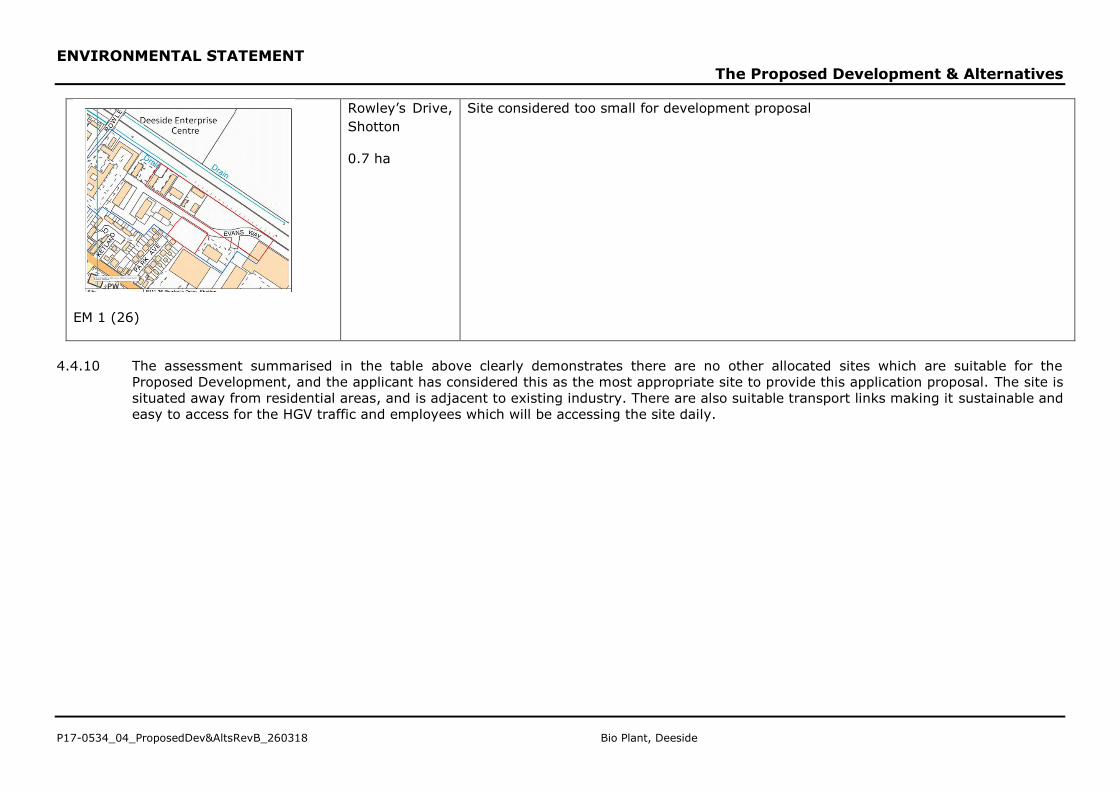
EM 1 (26)
Rowley’s Drive,
Shotton
0.7 ha
Site considered too small for development proposal
4.4.10 The assessment summarised in the table above clearly demonstrates there are no other allocated sites which are suitable for the
Proposed Development, and the applicant has considered this as the most appropriate site to provide this application proposal. The site is
situated away from residential areas, and is adjacent to existing industry. There are also suitable transport links making it sustainable and
easy to access for the HGV traffic and employees which will be accessing the site daily.
ENVIRONMENTAL STATEMENT
The Proposed Development & Alternatives
Bio Plant, Deeside P17-0534_04_ProposedDev&AltsRevB_260318
Alternative Designs
4.4.11 The constraints and opportunities presented by the Application Site and required
technology have been used to inform the design principles, which in turn have
helped refine and structure the Proposed Development.
4.4.12 The Design and Access Statement (DAS) that accompanies the planning
application describes in detail the design evolution and concepts.
4.4.13 The design approach for the architectural elements on the site has been driven by
the process that the building encloses, with a ‘form follows function’ approach.
That said how the building responds to its context has also been considered.
4.4.14 In terms of scale, the dimensions of the building have ultimately been determined
by the process plant dimensions and required clearances within, however every
effort to minimise the overall mass of the building has been taken by ensuring an
efficient structural solution and low profile, simple architectural solution. Shallow
pitch roofs hidden behind low parapets allow for a very simple rectangular form,
articulated by suspended canopies providing shelter at the drop off/pick up ends of
the process. To the east the building is further articulated by a second smaller
rectangular form which houses the RDF Hall at ground floor level and office, welfare
and control facilities over a partial first floor. Expressed circulation cores provide
vertical relief from the otherwise strongly horizontal aesthetic.
4.4.15 Responding to context the proposals follow a strongly industrial aesthetic with the
use of profiled coloured metal cladding across all elevations creating a clearly
contemporary response. The mass of the building is broken up with the use of
different colour tones and orientation profiling in the cladding to articulate the
different levels and create bands which pick up openings and canopies creating a
cohesive overall response. Areas of curtain wall glazing articulate vertical circulation
towers and mark the main pedestrian entrance to the facility. A further band of
intermittent glazing provides daylight and views out from the office and welfare
areas.