Embed Size (px)
Citation preview

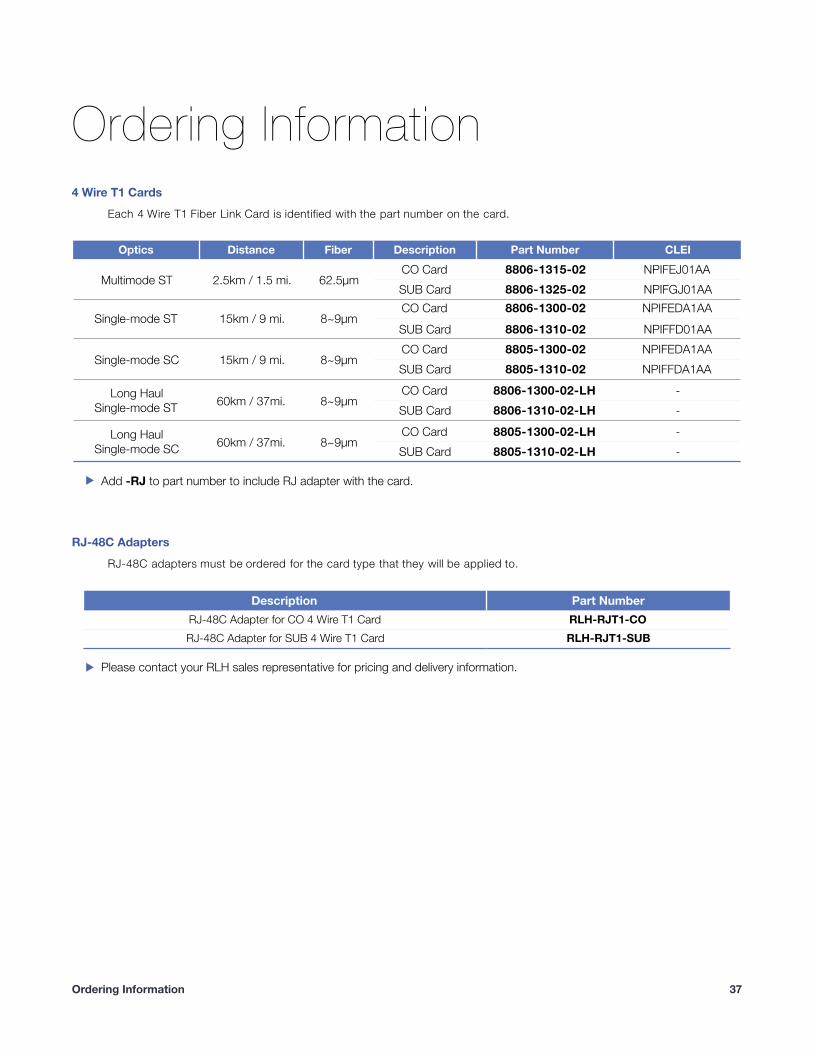
4 Wire T1 Fiber Link Card System
User Guide
U-001 2019A-0816

� RLH Industries, Inc.Copyright © 2019 RLH Industries, Inc. All rights reserved.No part of this document may be copied or distributed without permission.
The RLH logo may not be used for commercial purposes without the prior written consent of RLH and may constitute trademark infringement.
Other company and product names mentioned herein are trademarks of their respective companies. Mention of third-party products is for informational purposes only and constitutes neither an endorsement nor a recommendation. RLH assumes no responsibility with regard to the performance or use of these products.
The information contained in this document is the property of RLH Industries, Inc. and my not be reproduced or disseminated to third parties without the express written permission of RLH.
Every effort has been made to ensure that the information in this document is accurate. RLH is not responsible for printing or clerical errors. Because we are constantly seeking ways to improve our products, specifications and information contained in this document are subject to change without notice.
RLH Industries, Inc.936 North Main StreetOrange,CA 92867Ph. 714 532-1672email: [email protected]
�2
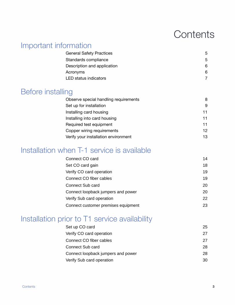
Contents Important information
General Safety Practices 5Standards compliance 5Description and application 6Acronyms 6LED status indicators 7
Before installing Observe special handling requirements 8Set up for installation 9Installing card housing 11Installing into card housing 11Required test equipment 11Copper wiring requirements 12Verify your installation environment 13
Installation when T-1 service is available Connect CO card 14
Set CO card gain 18
Verify CO card operation 19
Connect CO fiber cables 19
Connect Sub card 20
Connect loopback jumpers and power 20
Verify Sub card operation 22
Connect customer premises equipment 23
Installation prior to T1 service availability Set up CO card 25
Verify CO card operation 27
Connect CO fiber cables 27
Connect Sub card 28
Connect loopback jumpers and power 28
Verify Sub card operation 30
Contents �3
Troubleshooting Common Issues 31CO side troubleshooting 32Sub Side troubleshooting 32Power supply issues 33Verifying fiber cable 34Connecting T1 service after installation 36NIU Compatibility 36
Ordering Information 4 Wire T1 Cards 37RJ-48C Adapters 37
Specifications General Specifications 38
Support Technical Support 39Contact Information 39
� Contents4
Contents
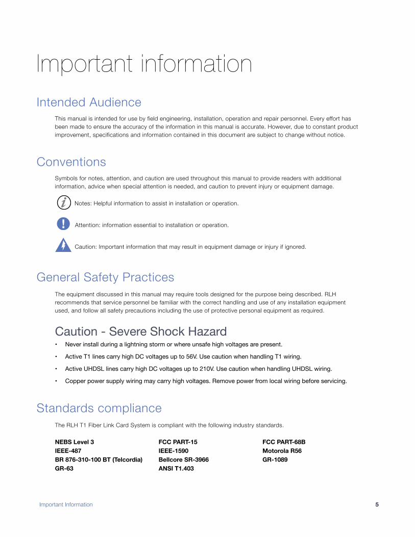
Important information Intended Audience
This manual is intended for use by field engineering, installation, operation and repair personnel. Every effort has been made to ensure the accuracy of the information in this manual is accurate. However, due to constant product improvement, specifications and information contained in this document are subject to change without notice.
Conventions Symbols for notes, attention, and caution are used throughout this manual to provide readers with additional information, advice when special attention is needed, and caution to prevent injury or equipment damage.
Notes: Helpful information to assist in installation or operation.
Attention: information essential to installation or operation.
Caution: Important information that may result in equipment damage or injury if ignored.
General Safety Practices The equipment discussed in this manual may require tools designed for the purpose being described. RLH recommends that service personnel be familiar with the correct handling and use of any installation equipment used, and follow all safety precautions including the use of protective personal equipment as required.
Caution - Severe Shock Hazard• Never install during a lightning storm or where unsafe high voltages are present.
• Active T1 lines carry high DC voltages up to 56V. Use caution when handling T1 wiring.
• Active UHDSL lines carry high DC voltages up to 210V. Use caution when handling UHDSL wiring.
• Copper power supply wiring may carry high voltages. Remove power from local wiring before servicing.
Standards compliance The RLH T1 Fiber Link Card System is compliant with the following industry standards.
NEBS Level 3 FCC PART-15 FCC PART-68BIEEE-487 IEEE-1590 Motorola R56BR 876-310-100 BT (Telcordia) Bellcore SR-3966 GR-1089GR-63 ANSI T1.403
Important Information �5
• Verify or repair before continuing
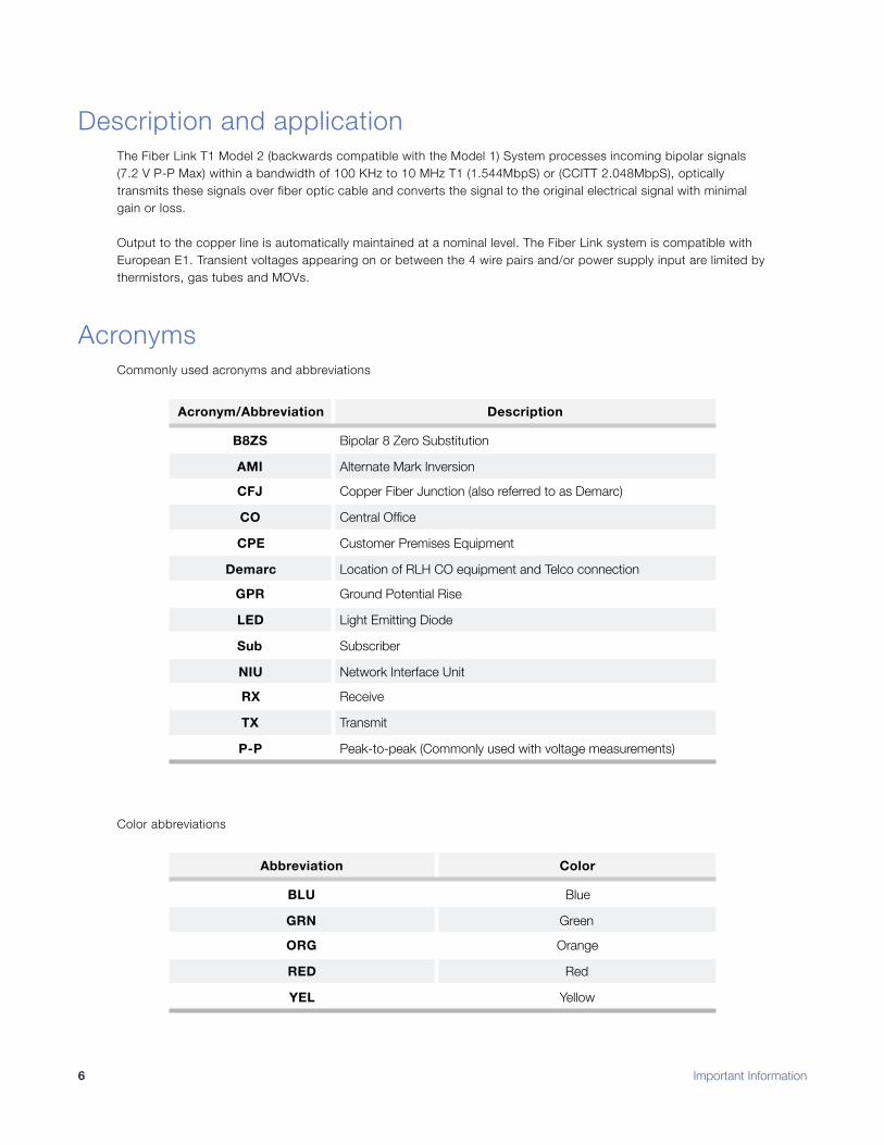
Description and application The Fiber Link T1 Model 2 (backwards compatible with the Model 1) System processes incoming bipolar signals (7.2 V P-P Max) within a bandwidth of 100 KHz to 10 MHz T1 (1.544MbpS) or (CCITT 2.048MbpS), optically transmits these signals over fiber optic cable and converts the signal to the original electrical signal with minimal gain or loss.
Output to the copper line is automatically maintained at a nominal level. The Fiber Link system is compatible with European E1. Transient voltages appearing on or between the 4 wire pairs and/or power supply input are limited by thermistors, gas tubes and MOVs.
Acronyms Commonly used acronyms and abbreviations
Color abbreviations
Acronym/Abbreviation Description
B8ZS Bipolar 8 Zero Substitution
AMI Alternate Mark Inversion
CFJ Copper Fiber Junction (also referred to as Demarc)
CO Central Office
CPE Customer Premises Equipment
Demarc Location of RLH CO equipment and Telco connection
GPR Ground Potential Rise
LED Light Emitting Diode
Sub Subscriber
NIU Network Interface Unit
RX Receive
TX Transmit
P-P Peak-to-peak (Commonly used with voltage measurements)
Abbreviation Color
BLU Blue
GRN Green
ORG Orange
RED Red
YEL Yellow
� Important Information6
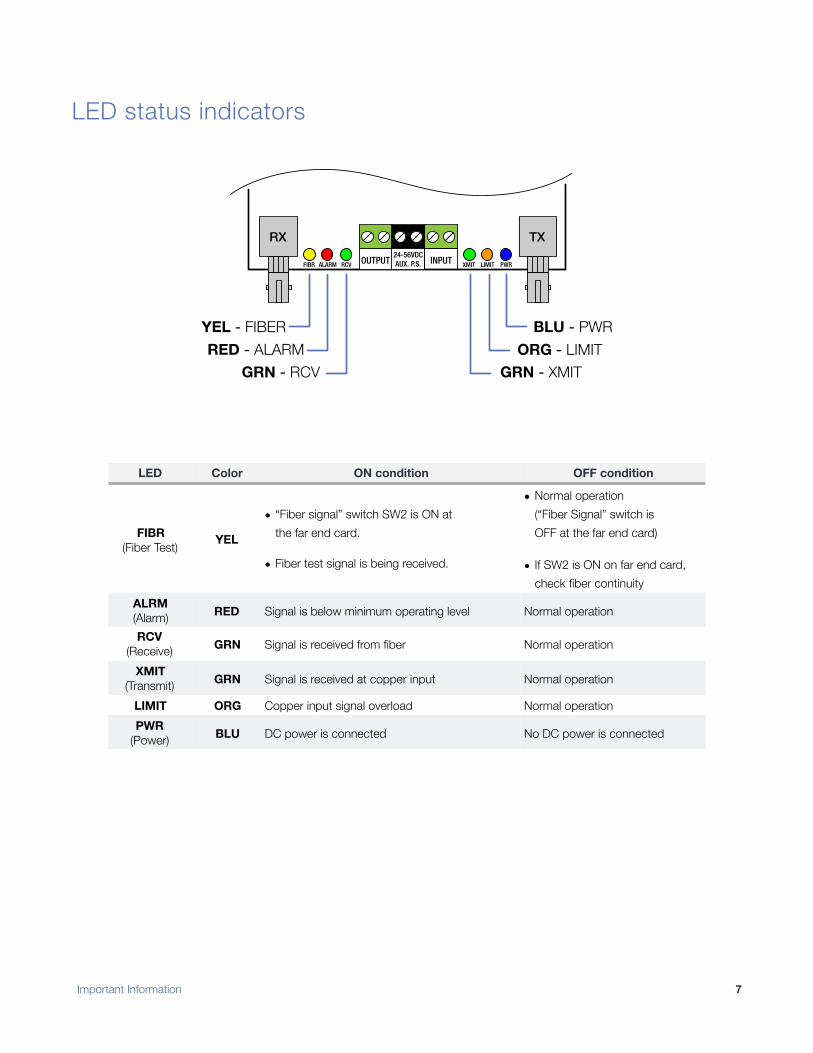
LED status indicators
!
OUTPUT24-56VDCAUX. P.S. INPUTFIBR RCV XMIT LIMIT PWRALARM
RX TX
YEL - FIBER
RED - ALARM
GRN - RCV
BLU - PWR
ORG - LIMIT
GRN - XMIT
LED Color ON condition OFF condition
FIBR(Fiber Test) YEL
• “Fiber signal” switch SW2 is ON at the far end card.
• Fiber test signal is being received.
• Normal operation(“Fiber Signal” switch is OFF at the far end card)
• If SW2 is ON on far end card, check fiber continuity
ALRM(Alarm) RED Signal is below minimum operating level Normal operation
RCV(Receive) GRN Signal is received from fiber Normal operation
XMIT(Transmit) GRN Signal is received at copper input Normal operation
LIMIT ORG Copper input signal overload Normal operationPWR
(Power) BLU DC power is connected No DC power is connected
Important Information �7
Before installing
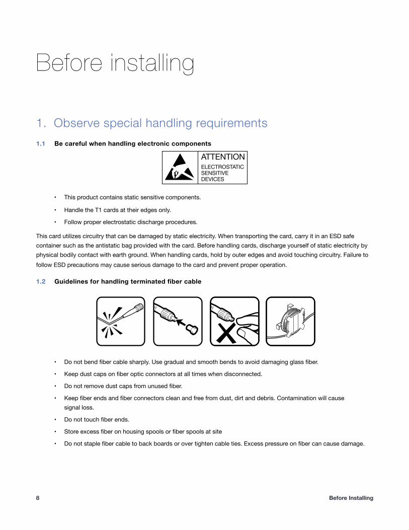
Observe special handling requirements 1.1 Be careful when handling electronic components
!
• This product contains static sensitive components.
• Handle the T1 cards at their edges only.
• Follow proper electrostatic discharge procedures.
This card utilizes circuitry that can be damaged by static electricity. When transporting the card, carry it in an ESD safe container such as the antistatic bag provided with the card. Before handling cards, discharge yourself of static electricity by physical bodily contact with earth ground. When handling cards, hold by outer edges and avoid touching circuitry. Failure to follow ESD precautions may cause serious damage to the card and prevent proper operation.
1.2 Guidelines for handling terminated fiber cable
!
• Do not bend fiber cable sharply. Use gradual and smooth bends to avoid damaging glass fiber.
• Keep dust caps on fiber optic connectors at all times when disconnected.
• Do not remove dust caps from unused fiber.
• Keep fiber ends and fiber connectors clean and free from dust, dirt and debris. Contamination will cause signal loss.
• Do not touch fiber ends.
• Store excess fiber on housing spools or fiber spools at site
• Do not staple fiber cable to back boards or over tighten cable ties. Excess pressure on fiber can cause damage.
ATTENTION
ELECTROSTATIC
SENSITIVE
DEVICES
� Before Installing8
1.
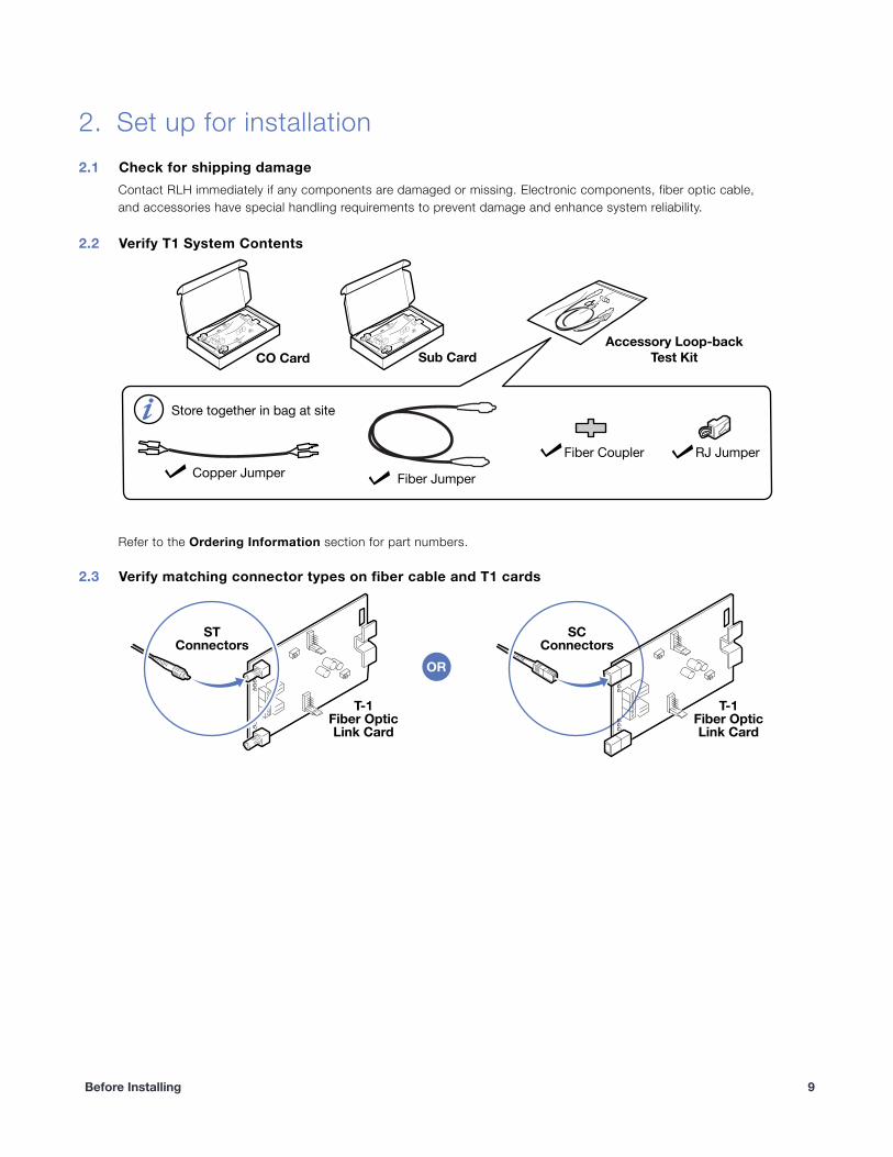
Set up for installation 2.1 Check for shipping damage
Contact RLH immediately if any components are damaged or missing. Electronic components, fiber optic cable, and accessories have special handling requirements to prevent damage and enhance system reliability.
2.2 Verify T1 System Contents
�
Refer to the Ordering Information section for part numbers.
2.3 Verify matching connector types on fiber cable and T1 cards
�
Fiber Jumper
Fiber Coupler
Copper Jumper
Store together in bag at site
RJ Jumper
CO Card Sub Card
Accessory Loop-back
Test Kit
ST
Connectors
T-1
Fiber Optic
Link Card
T-1
Fiber Optic
Link Card
SC
Connectors
OR
Before Installing �9
2.
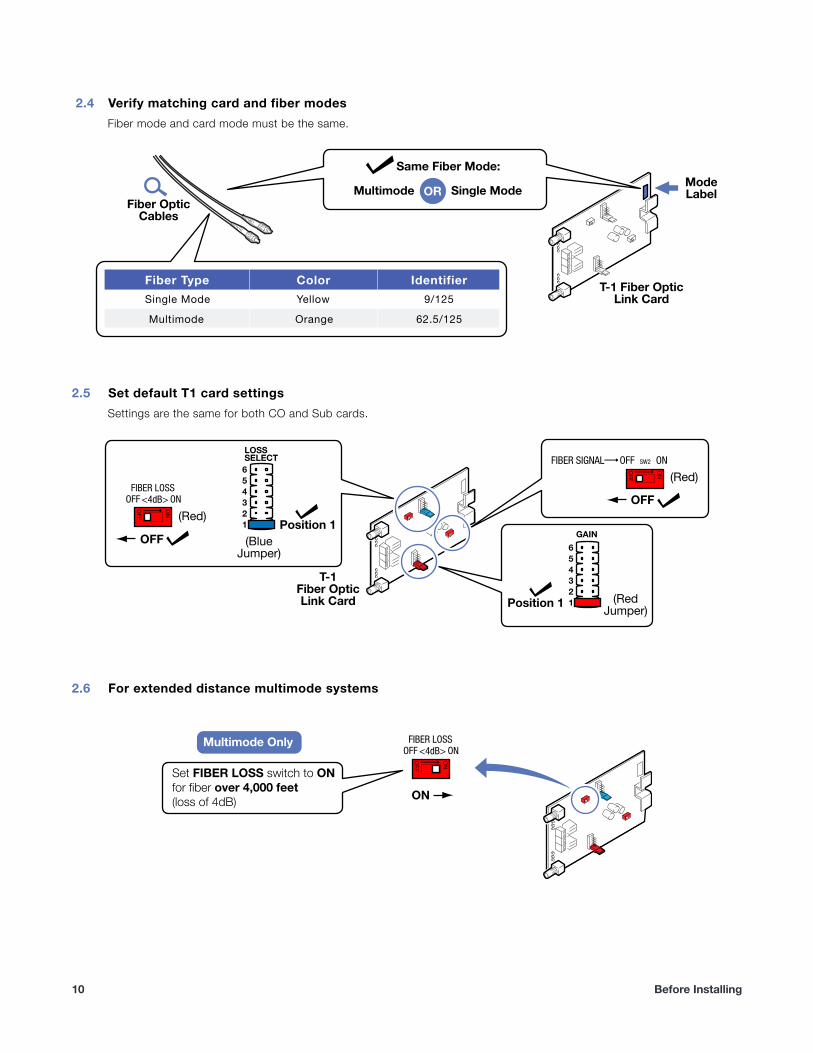
2.4 Verify matching card and fiber modes Fiber mode and card mode must be the same.
!
2.5 Set default T1 card settings Settings are the same for both CO and Sub cards.
!
2.6 For extended distance multimode systems
!
Fiber Type Color IdentifierSingle Mode Yellow 9/125
Multimode Orange 62.5/125
Multimode
Same Fiber Mode:
Fiber Optic
Cables
T-1 Fiber Optic
Link Card
Mode
LabelSingle ModeOR
1
2
3
4
5
6
LOSSSELECT
(Blue
Jumper)
(Red)
(Red)
(Red
Jumper)1
2
3
4
5
6
GAIN
ON
OFF
ONOFFFIBER SIGNAL SW2
ON
OFF
ONOFFFIBER LOSS
<4dB> OFF
Position 1
OFF
T-1
Fiber Optic
Link Card Position 1
ON
OFF
ONOFFFIBER LOSS
<4dB>
Set FIBER LOSS switch to ON
for fiber over 4,000 feet
(loss of 4dB)
Multimode Only
ON
� Before Installing10
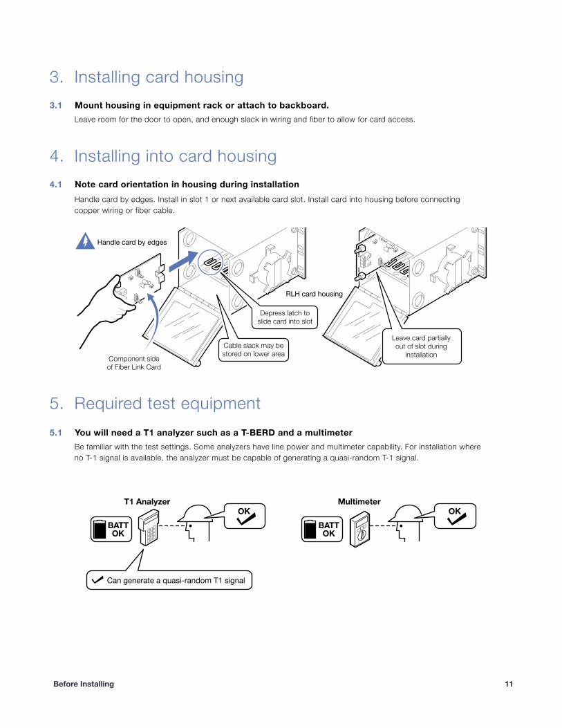
Installing card housing 3.1 Mount housing in equipment rack or attach to backboard.
Leave room for the door to open, and enough slack in wiring and fiber to allow for card access.
Installing into card housing 4.1 Note card orientation in housing during installation
Handle card by edges. Install in slot 1 or next available card slot. Install card into housing before connecting copper wiring or fiber cable.
!
Required test equipment 5.1 You will need a T1 analyzer such as a T-BERD and a multimeter
Be familiar with the test settings. Some analyzers have line power and multimeter capability. For installation where no T-1 signal is available, the analyzer must be capable of generating a quasi-random T-1 signal.
! Can generate a quasi-random T1 signal
OK
OK
BATT
T1 Analyzer
OK
OK
BATT
Multimeter
Before Installing �11
3.
4.
5.
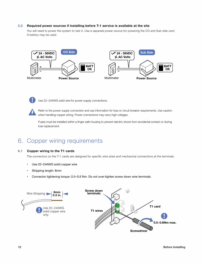
5.2 Required power sources if installing before T-1 service is available at the site You will need to power the system to test it. Use a separate power source for powering the CO and Sub side card. A battery may be used.
!
Copper wiring requirements 6.1 Copper wiring to the T1 cards
The connectors on the T-1 cards are designed for specific wire sizes and mechanical connections at the terminals.
• Use 22~24AWG solid copper wire
• Stripping length: 8mm
• Connector tightening torque: 0.5~0.6 Nm. Do not over-tighten screw down wire terminals.
�
+
–
24 - 56VDC
AC Volts
Power SourcePower Source
24 - 56VDC
AC Volts
OK
BATT+
–
Multimeter Multimeter
OK
BATT
Sub SideCO Side
Use 22~24AWG solid wire for power supply connections.
Refer to the power supply connection and use information for fuse or circuit breaker requirements. Use caution when handling copper wiring. Power connections may carry high voltages.
Fuses must be installed within a finger safe housing to prevent electric shock from accidental contact or during fuse replacement.
�
�
Use 22~24AWGsolid copper wireonly.
Wire Stripping 8mm0.3 in.
T1 wiresT1 card
0.5~0.6Nm max.
Screwdriver
Screw downterminals
� Before Installing12
6.
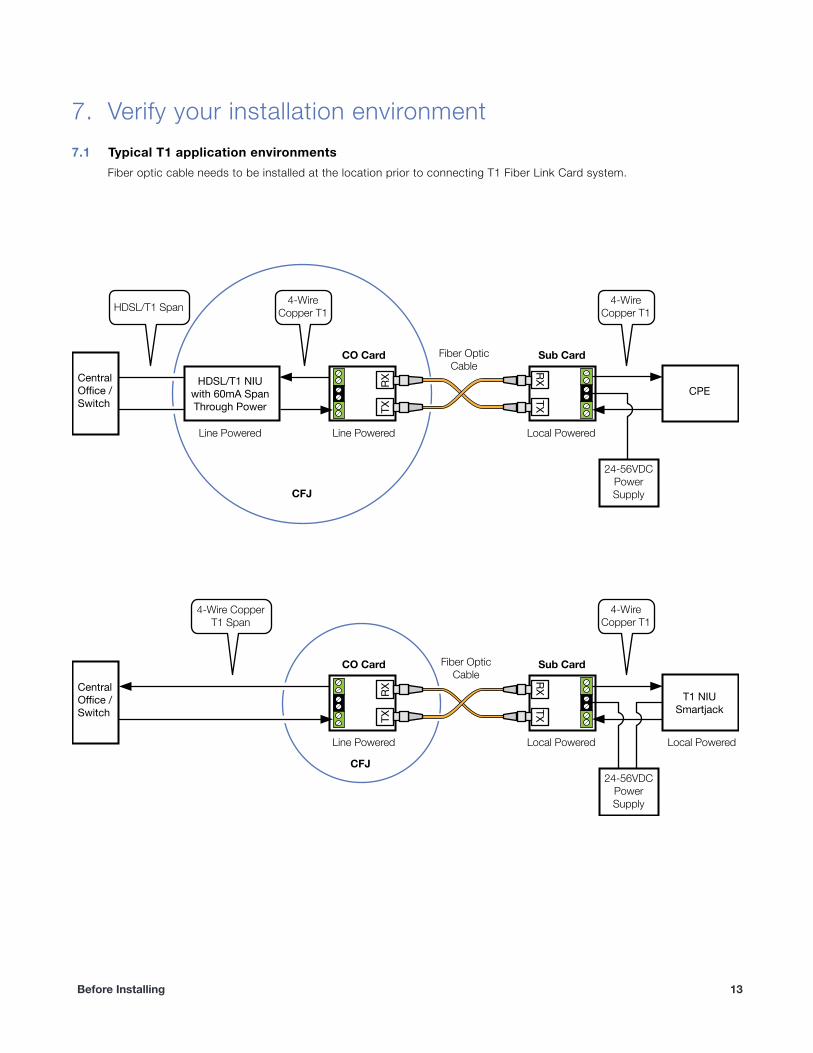
Verify your installation environment 7.1 Typical T1 application environments
Fiber optic cable needs to be installed at the location prior to connecting T1 Fiber Link Card system.
!
CentralOffice /Switch
HDSL/T1 NIUwith 60mA SpanThrough Power
Line Powered Line Powered
CO Card Sub Card
CFJ
CFJ
Local Powered
24-56VDCPowerSupply
CPE
4-WireCopper T1HDSL/T1 Span
Fiber OpticCable
4-WireCopper T1
RX
TX
RX
TX
CentralOffice /Switch
Line Powered
CO Card Sub Card
Local Powered Local Powered
24-56VDCPowerSupply
T1 NIUSmartjack
4-Wire CopperT1 Span
Fiber OpticCable
4-WireCopper T1
RX
TX
RX
TX
Before Installing �13
7.
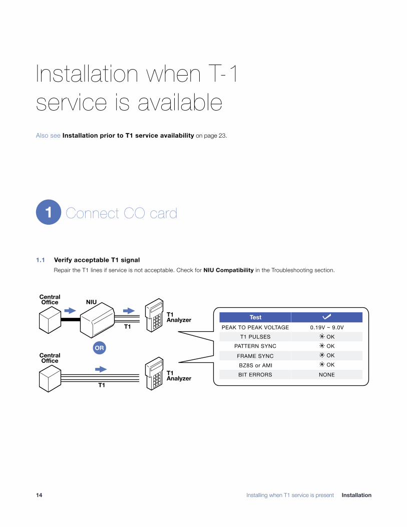
Installation when T-1 service is available Also see Installation prior to T1 service availability on page 23.
Connect CO card
1.1 Verify acceptable T1 signal Repair the T1 lines if service is not acceptable. Check for NIU Compatibility in the Troubleshooting section.
!
1
TestPEAK TO PEAK VOLTAGE 0.19V ~ 9.0V
T1 PULSESPATTERN SYNC
FRAME SYNCBZ8S or AMIBIT ERRORS NONE
� OK
� OK� OK
�
� OK
NIU
T1
CentralOffice
T1Analyzer
T1
CentralOffice
T1Analyzer
OR
� Installing when T1 service is present Installation14
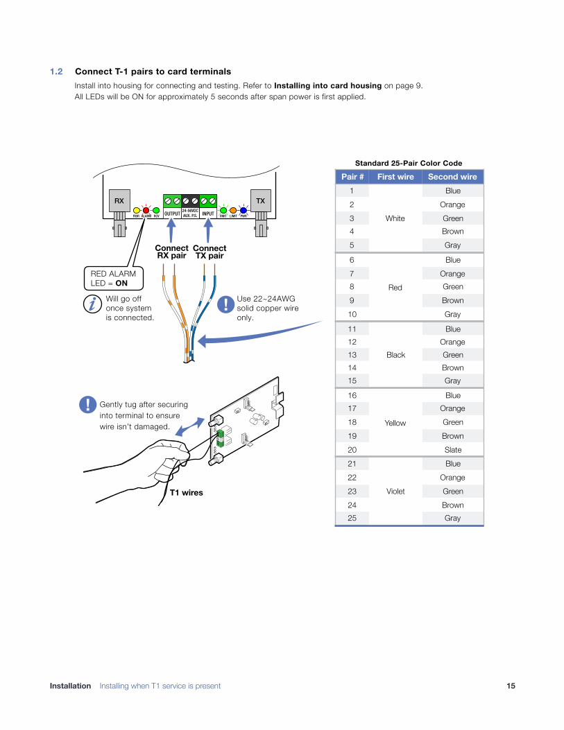
1.2 Connect T-1 pairs to card terminals Install into housing for connecting and testing. Refer to Installing into card housing on page 9. All LEDs will be ON for approximately 5 seconds after span power is first applied.
!
Pair # First wire Second wire1
White
Blue2 Orange3 Green4 Brown5 Gray
6
Red
Blue7 Orange8 Green9 Brown10 Gray
11
Black
Blue12 Orange13 Green14 Brown15 Gray
16
Yellow
Blue17 Orange18 Green19 Brown20 Slate21
Violet
Blue22 Orange23 Green24 Brown25 Gray
Standard 25-Pair Color Code
OUTPUT24-56VDCAUX. P.S. INPUTFIBR RCV XMIT LIMIT PWRALARM
RX TX
ConnectTX pair
ConnectRX pair
RED ALARMLED = ON
Will go offonce systemis connected.
Use 22~24AWGsolid copper wireonly.
T1 wires
Gently tug after securing into terminal to ensure wire isn’t damaged.
Installation Installing when T1 service is present �15
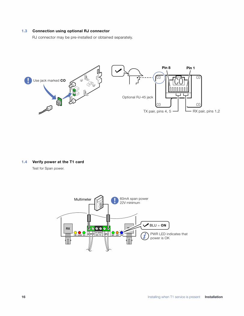
1.3 Connection using optional RJ connector RJ connector may be pre-installed or obtained separately.
!
1.4 Verify power at the T1 card Test for Span power.
!
Pin 1Pin 8
Use jack marked CO
Optional RJ-45 jack
COCO
CO
CO
CO
RX pair, pins 1,2TX pair, pins 4, 5
OUTPUT24-56VDCAUX. P.S. INPUTFIBR RCV XMIT LIMIT PWRALARM
RX TX
PWR LED indicates that
power is OK
60mA span power
22V minimum
Multimeter
BLU = ON
� Installing when T1 service is present Installation16
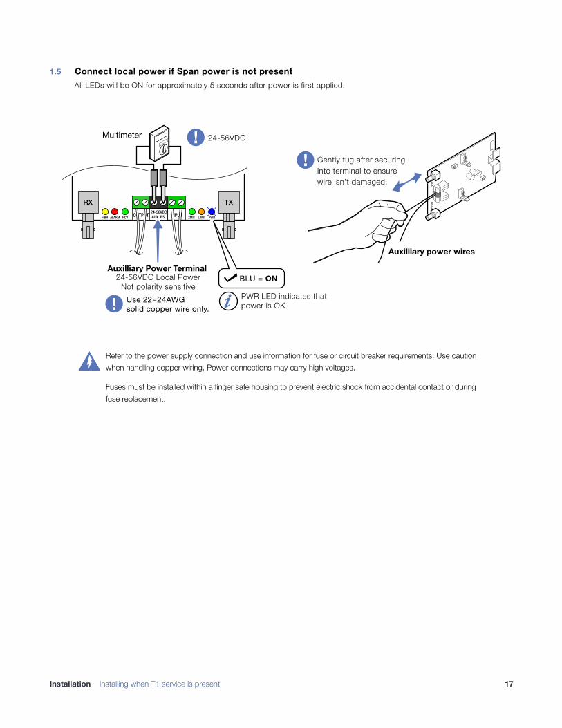
1.5 Connect local power if Span power is not present All LEDs will be ON for approximately 5 seconds after power is first applied.
!
Auxilliary power wires
Gently tug after securing
into terminal to ensure
wire isn’t damaged.
OUTPUT24-56VDCAUX. P.S. INPUTFIBR RCV XMIT LIMIT PWRALARM
RX TX
PWR LED indicates that
power is OK
Multimeter
BLU = ON
Auxilliary Power Terminal
24-56VDC Local Power
Not polarity sensitive
24-56VDC
Use 22~24AWGsolid copper wire only.
Refer to the power supply connection and use information for fuse or circuit breaker requirements. Use caution when handling copper wiring. Power connections may carry high voltages.
Fuses must be installed within a finger safe housing to prevent electric shock from accidental contact or during fuse replacement.
�
Installation Installing when T1 service is present �17
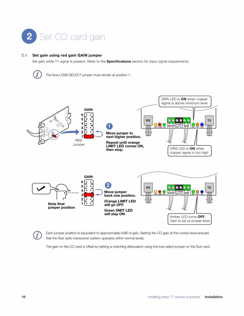
Set CO card gain
2.1 Set gain using red gain GAIN jumper Set gain while T1 signal is present. Refer to the Specifications section for input signal requirements.
!
2
The blue LOSS SELECT jumper must remain at position 1.�
1
2
3
4
5
6
GAIN
Move jumper to
next higher position.
Repeat until orange
LIMIT LED comes ON,
then stop.
OUTPUT24-56VDCAUX. P.S. INPUTFIBR RCV XMIT LIMIT PWRALARM
RX TX
ORG LED is ON when
copper signal is too high
RED
Jumper
1
2
3
4
5
6
GAIN
Move jumper
back one position.
Orange LIMIT LED
will go OFF.
Green XMIT LED
will stay ON.
Note final
jumper position
OUTPUT24-56VDCAUX. P.S. INPUTFIBR RCV XMIT LIMIT PWRALARM
RX TX
Amber LED turns OFF.
Gain is set at proper level.
1
2
GRN LED is ON when copper
signal is above minimum level
Each jumper position is equivalent to approximately 6dB of gain. Setting the CO gain at the correct level ensures that the fiber optic transceiver system operates within normal levels.
The gain on the CO card is offset by setting a matching attenuation using the loss select jumper on the Sub card.
�
� Installing when T1 service is present Installation18
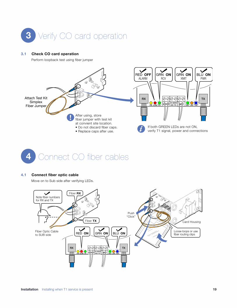
Verify CO card operation
3.1 Check CO card operation Perform loopback test using fiber jumper
!
Connect CO fiber cables
4.1 Connect fiber optic cable Move on to Sub side after verifying LEDs.
!
3
Attach Test KitSimplex
Fiber Jumper OUTPUT24-56VDCAUX. P.S. INPUTFIBR RCV XMIT LIMIT PWRALARM
RX TX
OFFREDALARM RCV XMIT PWR
ONGRN GRN BLUON ON
After using, storefiber jumper with test kitat convient site location.• Do not discard fiber caps.
• Replace caps after use.
If both GREEN LEDs are not ON,
verify T1 signal, power and connections
4
OUTPUT24-56VDCAUX. P.S. INPUTFIBR RCV XMIT LIMIT PWRALARM
RX TX
Fiber RX
Note fiber numbersfor RX and TX
Loose loops or usefiber routing clips
Fiber TX
GRN ONRED ON BLU ON Fiber Optic Cableto SUB side
Card Housing
Push“Click”
Installation Installing when T1 service is present �19
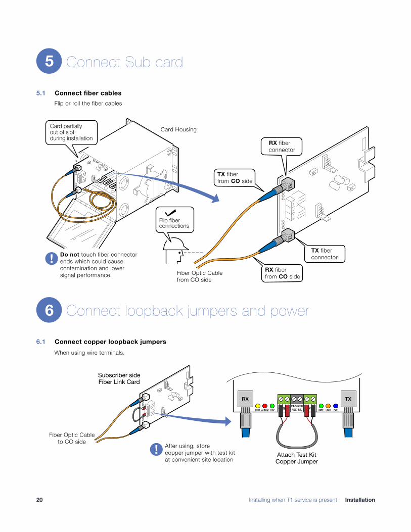
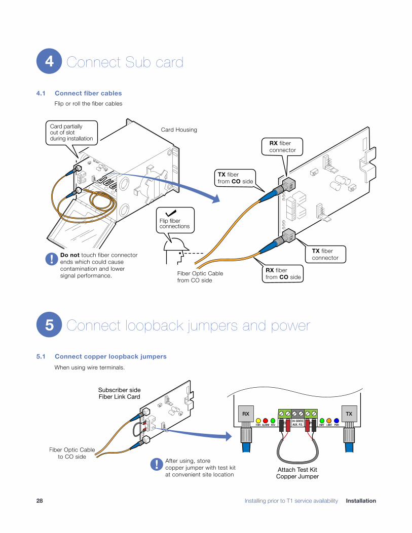
Connect Sub card
5.1 Connect fiber cables Flip or roll the fiber cables
!
Connect loopback jumpers and power
6.1 Connect copper loopback jumpers When using wire terminals.
�
5
TX fiberconnector
RX fiberfrom CO side
RXTX
Flip fiberconnections
TX fiberfrom CO side
RX fiberconnector
Do not touch fiber connectorends which could causecontamination and lowersignal performance.
Card partiallyout of slotduring installation
Fiber Optic Cablefrom CO side
Card Housing
6
� Installing when T1 service is present Installation20
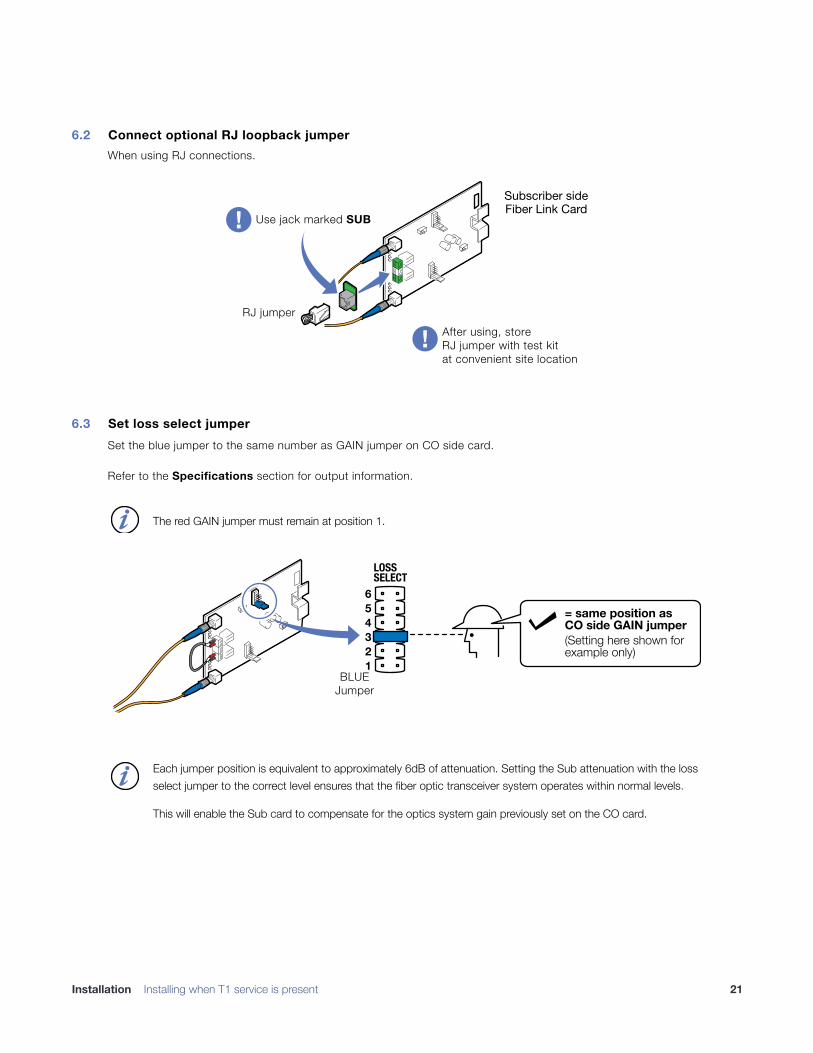
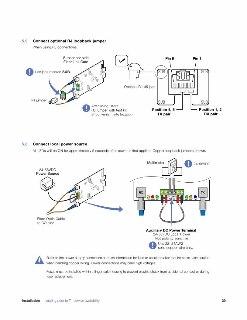
6.2 Connect optional RJ loopback jumper When using RJ connections.
!
6.3 Set loss select jumper Set the blue jumper to the same number as GAIN jumper on CO side card.
Refer to the Specifications section for output information.
!
The red GAIN jumper must remain at position 1.�
1
2
3
4
5
6
LOSSSELECT
BLUEJumper
= same position as
CO side GAIN jumper
(Setting here shown forexample only)
Each jumper position is equivalent to approximately 6dB of attenuation. Setting the Sub attenuation with the loss select jumper to the correct level ensures that the fiber optic transceiver system operates within normal levels.
This will enable the Sub card to compensate for the optics system gain previously set on the CO card.
�
Installation Installing when T1 service is present �21
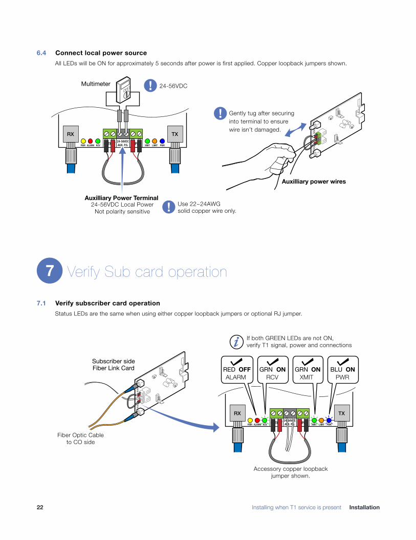
6.4 Connect local power source All LEDs will be ON for approximately 5 seconds after power is first applied. Copper loopback jumpers shown.
!
Verify Sub card operation
7.1 Verify subscriber card operation Status LEDs are the same when using either copper loopback jumpers or optional RJ jumper.
!
Auxilliary power wires
Gently tug after securing into terminal to ensure wire isn’t damaged.
OUTPUT24-56VDCAUX. P.S. INPUTFIBR RCV XMIT LIMIT PWRALARM
RX TX
Auxilliary Power Terminal24-56VDC Local Power
Not polarity sensitive
Multimeter 24-56VDC
Use 22~24AWGsolid copper wire only.
7
� Installing when T1 service is present Installation22
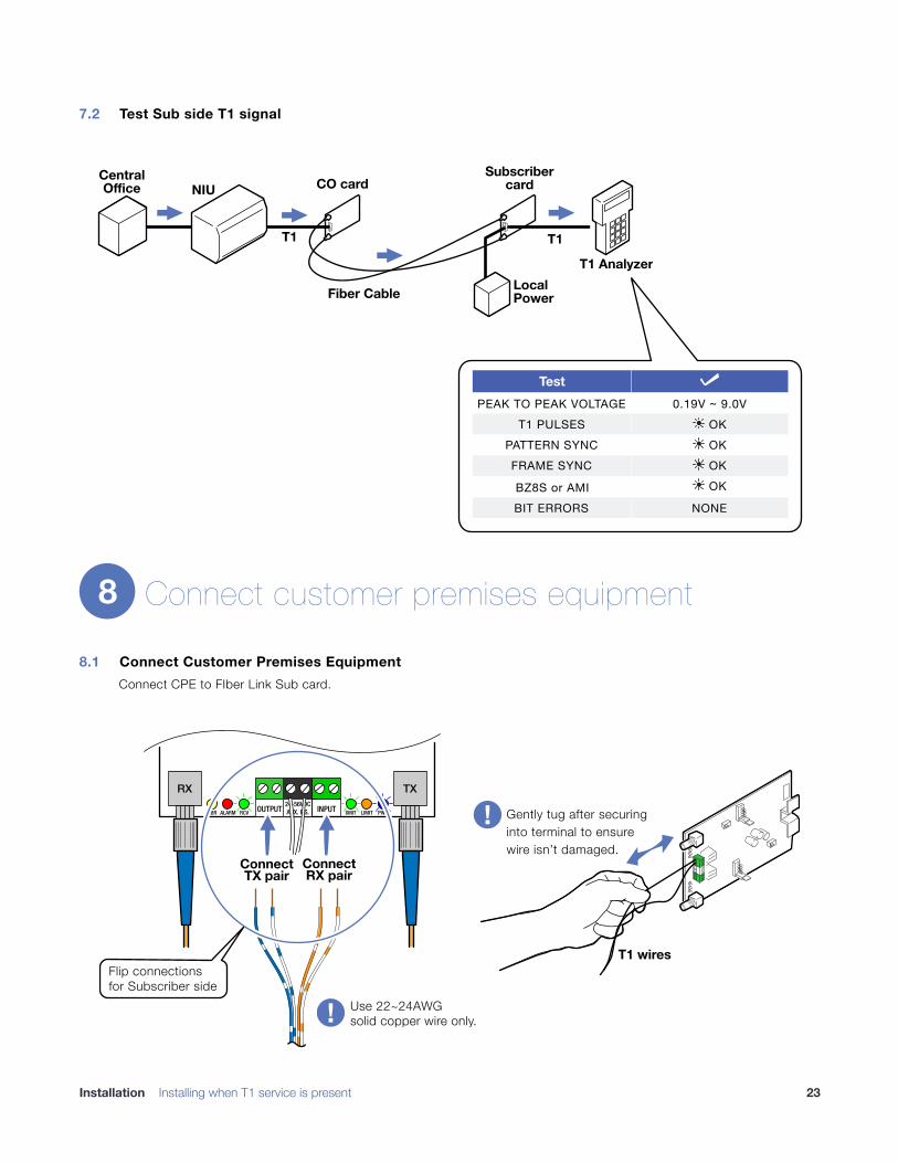
7.2 Test Sub side T1 signal
!
Connect customer premises equipment
8.1 Connect Customer Premises Equipment Connect CPE to FIber Link Sub card.
!
TestPEAK TO PEAK VOLTAGE 0.19V ~ 9.0V
T1 PULSESPATTERN SYNCFRAME SYNC
BZ8S or AMIBIT ERRORS NONE
� OK
� OK� OK
�
� OK
NIU
T1 T1
CO card
Subscriber
card
Local
Power
T1 Analyzer
Fiber Cable
Central
Office
8
Use 22~24AWGsolid copper wire only.
OUTPUT24-56VDCAUX. P.S. INPUTFIBR RCV XMIT LIMIT PWRALARM
RX TX
ConnectTX pair
ConnectRX pair
T1 wires
Gently tug after securing into terminal to ensure wire isn’t damaged.
Flip connectionsfor Subscriber side
Installation Installing when T1 service is present �23
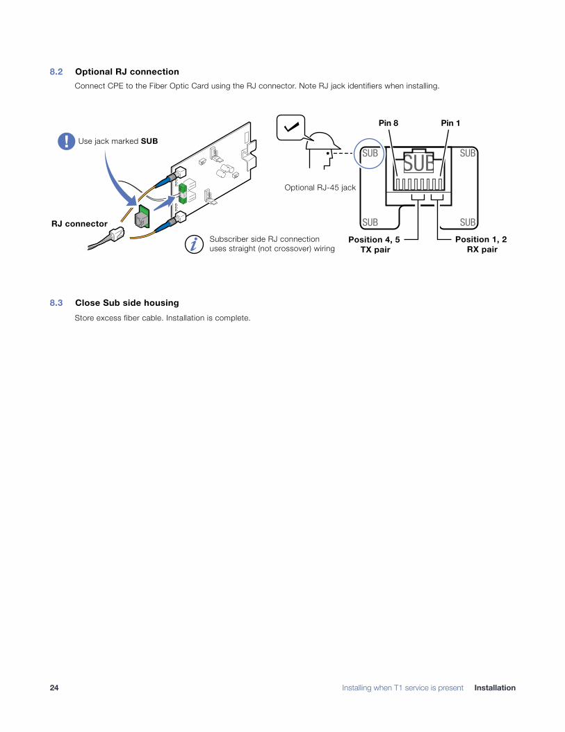
8.2 Optional RJ connection Connect CPE to the Fiber Optic Card using the RJ connector. Note RJ jack identifiers when installing.
!
8.3 Close Sub side housing Store excess fiber cable. Installation is complete.
Pin 1Pin 8
Use jack marked SUB
Subscriber side RJ connection
uses straight (not crossover) wiring
SUBOptional RJ-45 jack
SUB
SUB
SUB
SUBRJ connector
Position 1, 2 RX pair
Position 4, 5 TX pair
� Installing when T1 service is present Installation24
Installation prior to T1 service availability Also see Installation when T1 service is available on page 13
Set up CO card
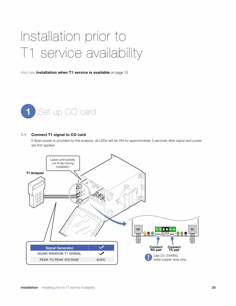
1.1 Connect T1 signal to CO card If Span power is provided by the analyzer, all LEDs will be ON for approximately 5 seconds after signal and power are first applied.
�
1
Use 22~24AWGsolid copper wire only.
T1 Analyzer
OUTPUT24-56VDCAUX. P.S. INPUTFIBR RCV XMIT LIMIT PWRALARM
RX TX
ConnectTX pair
ConnectRX pair
Leave card partiallyout of slot during
installation
Signal GeneratorQUASI-RANDOM T1 SIGNAL
PEAK TO PEAK VOLTAGE 6VDC�
�
Installation Installing prior to T1 service availability �25
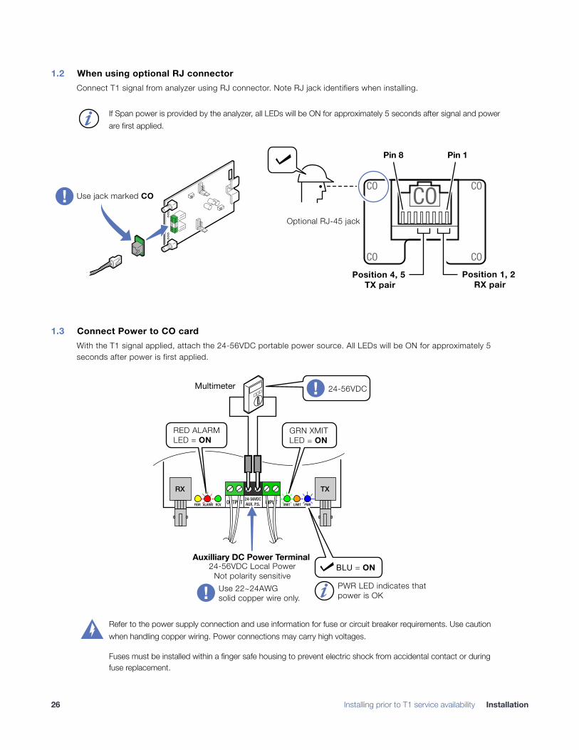
1.2 When using optional RJ connector Connect T1 signal from analyzer using RJ connector. Note RJ jack identifiers when installing.
!
1.3 Connect Power to CO card With the T1 signal applied, attach the 24-56VDC portable power source. All LEDs will be ON for approximately 5 seconds after power is first applied.
�
If Span power is provided by the analyzer, all LEDs will be ON for approximately 5 seconds after signal and power are first applied.�
Pin 1Pin 8
COUse jack marked CO
Optional RJ-45 jack
CO
CO
CO
CO
Position 1, 2 RX pair
Position 4, 5 TX pair
Use 22~24AWGsolid copper wire only.
OUTPUT24-56VDCAUX. P.S. INPUTFIBR RCV XMIT LIMIT PWRALARM
RX TX
PWR LED indicates that
power is OK
Multimeter
BLU = ON
Auxilliary DC Power Terminal
24-56VDC Local Power
Not polarity sensitive
24-56VDC
RED ALARM
LED = ON
GRN XMIT
LED = ON
Refer to the power supply connection and use information for fuse or circuit breaker requirements. Use caution when handling copper wiring. Power connections may carry high voltages.
Fuses must be installed within a finger safe housing to prevent electric shock from accidental contact or during fuse replacement.
�
� Installing prior to T1 service availability Installation26
Verify CO card operation
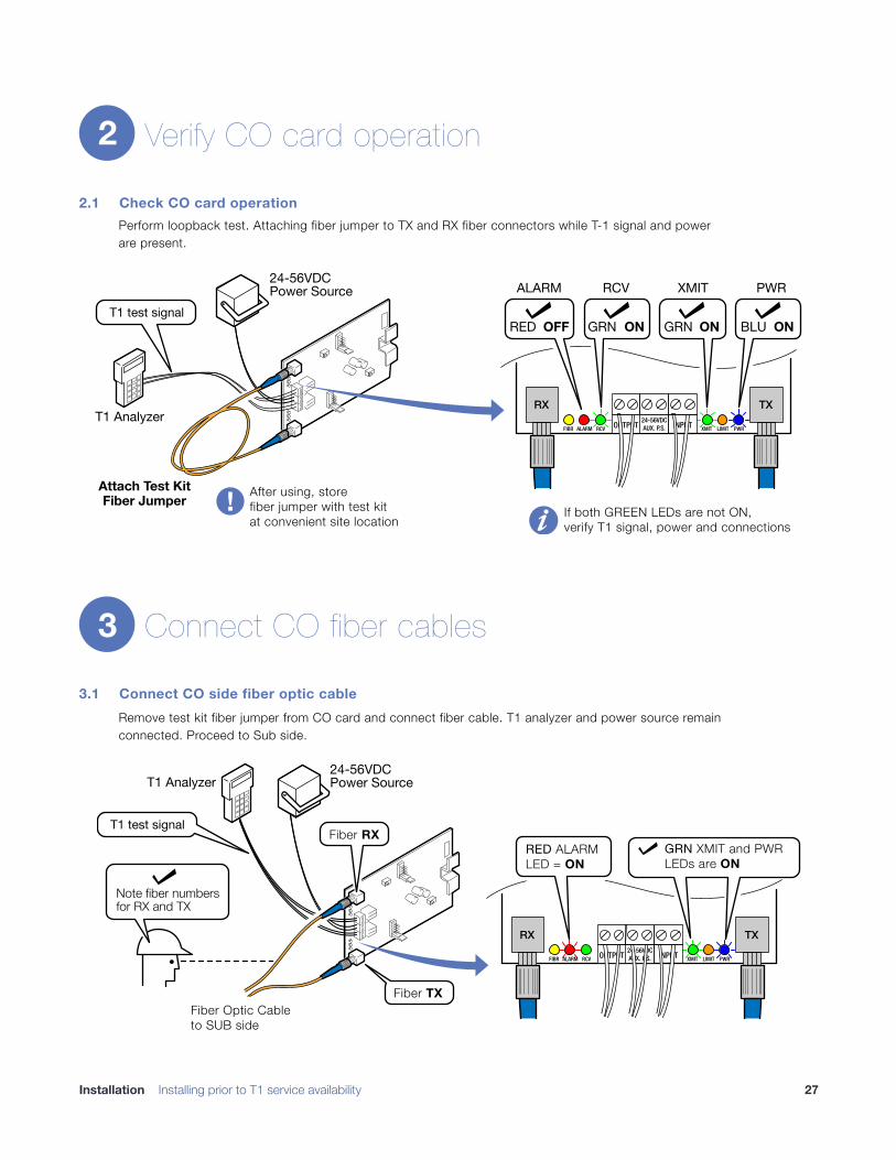
2.1 Check CO card operation Perform loopback test. Attaching fiber jumper to TX and RX fiber connectors while T-1 signal and power are present.
!
Connect CO fiber cables
3.1 Connect CO side fiber optic cable Remove test kit fiber jumper from CO card and connect fiber cable. T1 analyzer and power source remain connected. Proceed to Sub side.
�
2
Attach Test Kit
Fiber Jumper
OUTPUT24-56VDCAUX. P.S. INPUTFIBR RCV XMIT LIMIT PWRALARM
RX TX
OFFRED ONGRN
RCVALARM PWRXMIT
GRN BLUON ON
T1 test signal
T1 Analyzer
24-56VDCPower Source
After using, store
fiber jumper with test kit
at convenient site locationIf both GREEN LEDs are not ON,
verify T1 signal, power and connections
3
OUTPUT24-56VDCAUX. P.S. INPUTFIBR RCV XMIT LIMIT PWRALARM
RX TX
GRN XMIT and PWR
LEDs are ON
Fiber RX
Fiber TX
RED ALARM
LED = ON
Note fiber numbers
for RX and TX
T1 test signal
T1 Analyzer24-56VDCPower Source
Fiber Optic Cable
to SUB side
Installation Installing prior to T1 service availability �27
Connect Sub card
4.1 Connect fiber cables Flip or roll the fiber cables
!
Connect loopback jumpers and power
5.1 Connect copper loopback jumpers When using wire terminals.
�
4
TX fiberconnector
RX fiberfrom CO side
RXTX
Flip fiberconnections
TX fiberfrom CO side
RX fiberconnector
Do not touch fiber connectorends which could causecontamination and lowersignal performance.
Card partiallyout of slotduring installation
Fiber Optic Cablefrom CO side
Card Housing
5
� Installing prior to T1 service availability Installation28
5.2 Connect optional RJ loopback jumper When using RJ connections.
!
5.3 Connect local power source All LEDs will be ON for approximately 5 seconds after power is first applied. Copper loopback jumpers shown.
! Use 22~24AWGsolid copper wire only.
OUTPUT24-56VDCAUX. P.S. INPUTFIBR RCV XMIT LIMIT PWRALARM
RX TX
Auxilliary DC Power Terminal24-56VDC Local Power
Not polarity sensitive
Multimeter 24-56VDC
24-56VDCPower Source
Fiber Optic Cable
to CO side
Refer to the power supply connection and use information for fuse or circuit breaker requirements. Use caution when handling copper wiring. Power connections may carry high voltages.
Fuses must be installed within a finger safe housing to prevent electric shock from accidental contact or during fuse replacement.
�
Installation Installing prior to T1 service availability �29
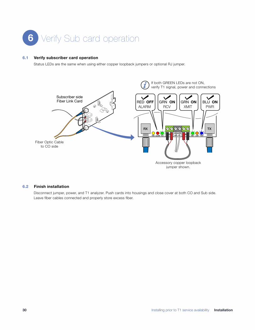
Verify Sub card operation
6.1 Verify subscriber card operation Status LEDs are the same when using either copper loopback jumpers or optional RJ jumper.
!
6.2 Finish installation Disconnect jumper, power, and T1 analyzer. Push cards into housings and close cover at both CO and Sub side. Leave fiber cables connected and properly store excess fiber.
6
� Installing prior to T1 service availability Installation30
Troubleshooting
First Step: Isolate the problem Following the installation procedure will greatly speed any troubleshooting. It is designed to isolate different parts of the system during installation.
Isolating the source of trouble is essential to determining the steps needed to fix the problem. Most installation problems can be easily fixed in the field once the problem is properly identified.
Common Issues Most problems encountered during installation and testing can be attributed to these 4 issues:
• Problems with the CO side or incoming T1 signal
• Problems with the Sub side or T1 signal output
• Problems providing correct power to the cards
• Problems with the copper connections wiring due to nicking, scoring or poor terminating
• Problems with the fiber optic cable
RLH T1 cards are built to the highest standards and fully tested before leaving the factory.
Isolating and ruling out common issues with the installation will help determine if there is a problem with the card itself.
Troubleshooting �31
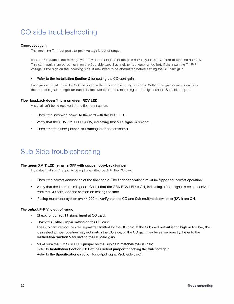
CO side troubleshooting Cannot set gain
The incoming T1 input peak-to-peak voltage is out of range.
If the P-P voltage is out of range you may not be able to set the gain correctly for the CO card to function normally. This can result in an output level on the Sub side card that is either too weak or too hot. If the Incoming T1 P-P voltage is too high on the incoming side, it may need to be attenuated before setting the CO card gain.
• Refer to the Installation Section 2 for setting the CO card gain.
Each jumper position on the CO card is equivalent to approximately 6dB gain. Setting the gain correctly ensures the correct signal strength for transmission over fiber and a matching output signal on the Sub side output.
Fiber loopback doesn’t turn on green RCV LED A signal isn’t being received at the fiber connection.
• Check the incoming power to the card with the BLU LED.
• Verify that the GRN XMIT LED is ON, indicating that a T1 signal is present.
• Check that the fiber jumper isn’t damaged or contaminated.
Sub Side troubleshooting
The green XMIT LED remains OFF with copper loop-back jumper Indicates that no T1 signal is being transmitted back to the CO card
• Check the correct connection of the fiber cable. The fiber connections must be flipped for correct operation.
• Verify that the fiber cable is good. Check that the GRN RCV LED is ON, indicating a fiber signal is being received from the CO card. See the section on testing the fiber.
• If using multimode system over 4,000 ft., verify that the CO and Sub multimode switches (SW1) are ON.
The output P-P V is out of range • Check for correct T1 signal input at CO card.
• Check the GAIN jumper setting on the CO card.The Sub card reproduces the signal transmitted by the CO card. If the Sub card output is too high or too low, the loss select jumper position may not match the CO side, or the CO gain may be set incorrectly. Refer to the Installation Section 2 for setting the CO card gain.
• Make sure the LOSS SELECT jumper on the Sub card matches the CO card.Refer to Installation Section 6.3 Set loss select jumper for setting the Sub card gain.Refer to the Specifications section for output signal (Sub side card).
� Troubleshooting 32
Power supply issues Blue PWR LED remains off
The T1 card isn’t receiving proper power.
• Check power by using a multimeter on the top of the screw-down terminals.
If using Span power
• Check across the INPUT and OUTPUT terminals. Power must be 22VDC minimum.
• Check the NIU compatibly chart for NIU systems providing span power.
• If Span power is too low or not provided, repair the T1 line or use an auxiliary power source.
• Check wiring for nicking, scoring or poor termination.
If using auxiliary power
• Check the AUX P.S. terminals for 24-56VDC, 55-75mA.
• No AC power can be detectable on the DC power line.
• Check wiring for nicking, scoring or poor termination.
Use 22~24AWG solid wire for power supply connections.
Refer to the power supply connection and use information for fuse or circuit breaker requirements. Use caution when handling copper wiring. Power connections may carry high voltages.
Fuses must be installed within a finger safe housing to prevent electric shock from accidental contact or during fuse replacement.
�
�
Troubleshooting �33
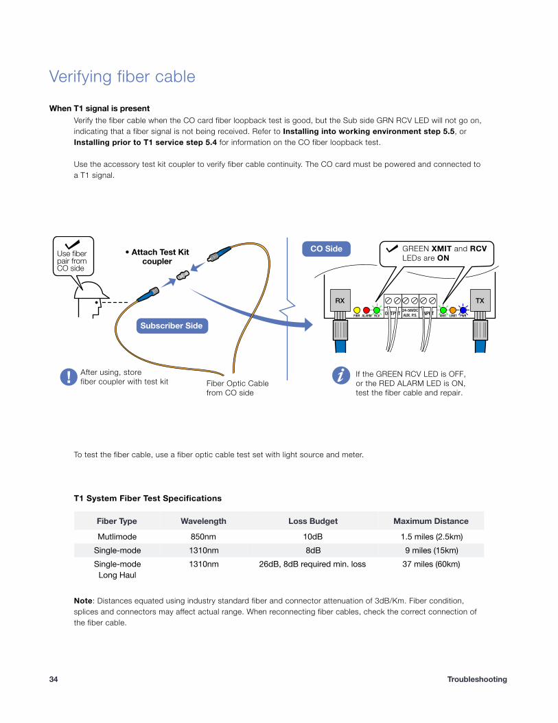
Verifying fiber cable When T1 signal is present
Verify the fiber cable when the CO card fiber loopback test is good, but the Sub side GRN RCV LED will not go on, indicating that a fiber signal is not being received. Refer to Installing into working environment step 5.5, or Installing prior to T1 service step 5.4 for information on the CO fiber loopback test.
Use the accessory test kit coupler to verify fiber cable continuity. The CO card must be powered and connected to a T1 signal.
!
To test the fiber cable, use a fiber optic cable test set with light source and meter.
T1 System Fiber Test Specifications
Note: Distances equated using industry standard fiber and connector attenuation of 3dB/Km. Fiber condition, splices and connectors may affect actual range. When reconnecting fiber cables, check the correct connection of the fiber cable.
• Attach Test Kit
coupler
OUTPUT24-56VDCAUX. P.S. INPUTFIBR RCV XMIT LIMIT PWRALARM
RX TX
GREEN XMIT and RCV
LEDs are ON
Subscriber Side
CO SideUse fiber
pair from
CO side
After using, store
fiber coupler with test kit
If the GREEN RCV LED is OFF,
or the RED ALARM LED is ON,
test the fiber cable and repair.
Fiber Optic Cable
from CO side
Fiber Type Wavelength Loss Budget Maximum Distance
Mutlimode 850nm 10dB 1.5 miles (2.5km)Single-mode 1310nm 8dB 9 miles (15km)Single-modeLong Haul
1310nm 26dB, 8dB required min. loss 37 miles (60km)
� Troubleshooting 34
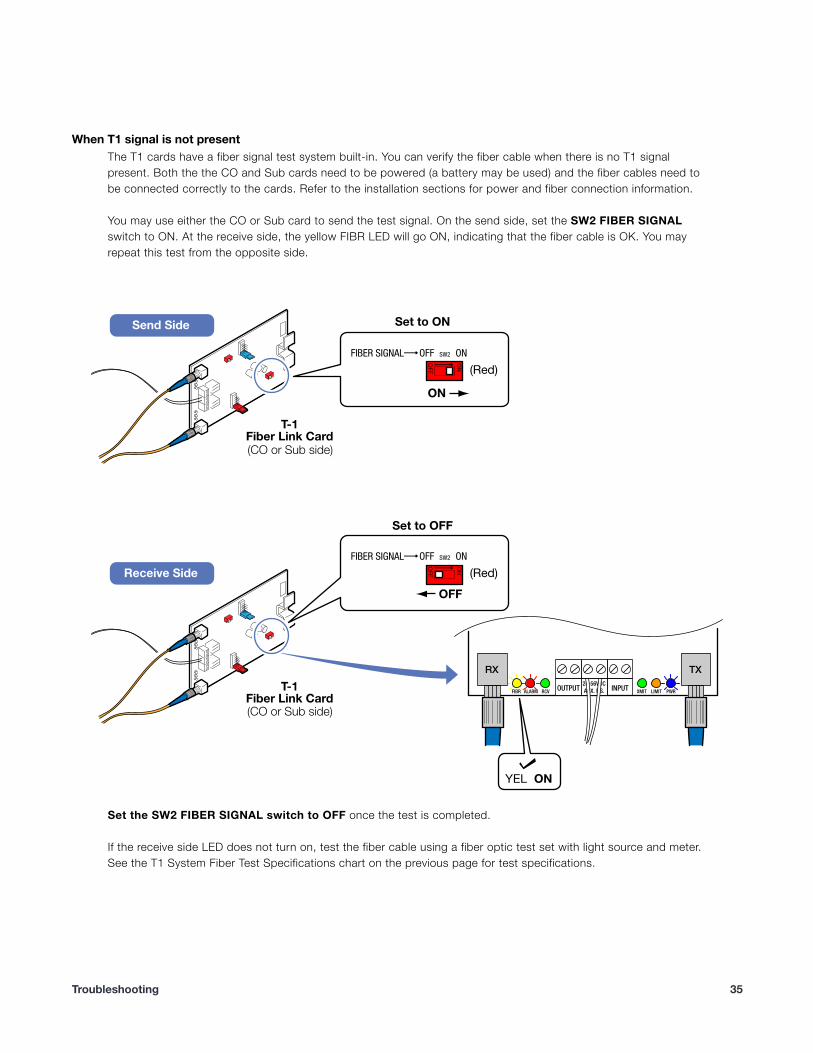
When T1 signal is not present The T1 cards have a fiber signal test system built-in. You can verify the fiber cable when there is no T1 signal present. Both the the CO and Sub cards need to be powered (a battery may be used) and the fiber cables need to be connected correctly to the cards. Refer to the installation sections for power and fiber connection information.
You may use either the CO or Sub card to send the test signal. On the send side, set the SW2 FIBER SIGNAL switch to ON. At the receive side, the yellow FIBR LED will go ON, indicating that the fiber cable is OK. You may repeat this test from the opposite side.
!
Set the SW2 FIBER SIGNAL switch to OFF once the test is completed.
If the receive side LED does not turn on, test the fiber cable using a fiber optic test set with light source and meter. See the T1 System Fiber Test Specifications chart on the previous page for test specifications.
Troubleshooting �35
Connecting T1 service after installation When connecting T1 Service AFTER the Fiber Link has been pre-installed, make sure to check the following.
• Verify span or auxiliary power to the CO card at the card terminals (page 15)
• Set the gain using the GAIN jumper on the CO card (page 16)
• Set the LOSS SELECT jumper on the Sub card to the same setting as the GAIN jumper on the CO card (page 19)
• Verify auxiliary power to the Sub card at the card terminals (page 20)
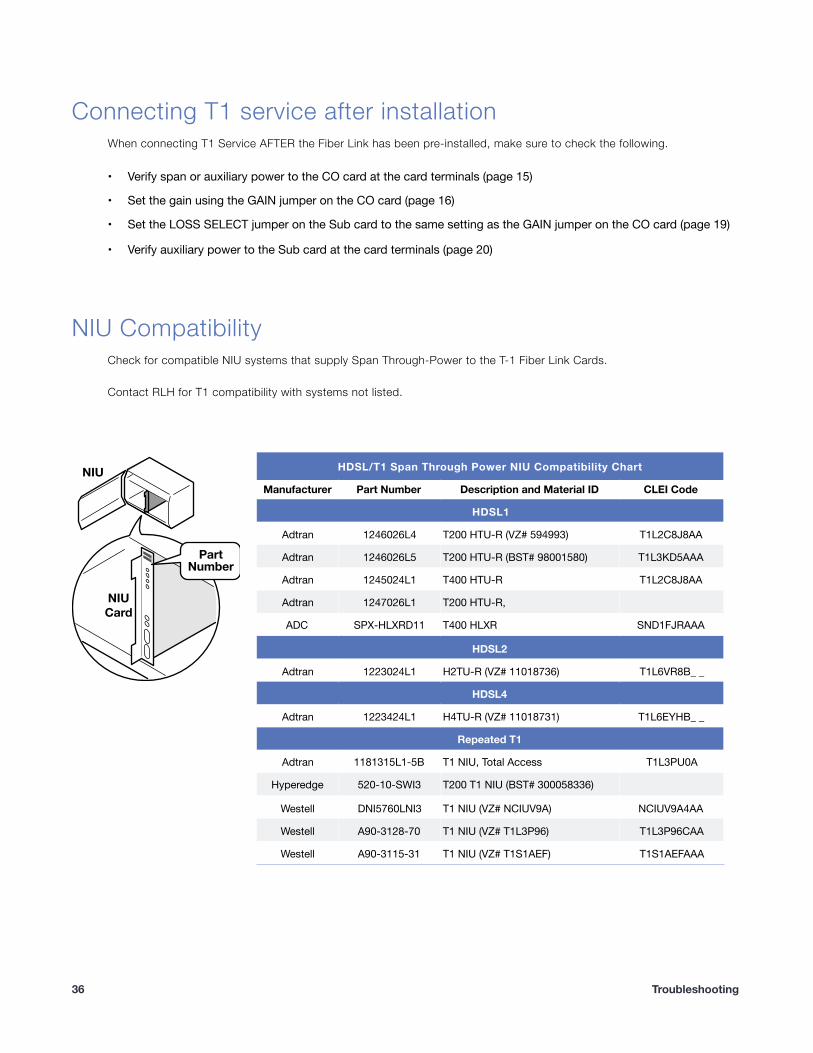
NIU Compatibility Check for compatible NIU systems that supply Span Through-Power to the T-1 Fiber Link Cards.
Contact RLH for T1 compatibility with systems not listed.
!
HDSL/T1 Span Through Power NIU Compatibility Chart
Manufacturer Part Number Description and Material ID CLEI Code
HDSL1
Adtran 1246026L4 T200 HTU-R (VZ# 594993) T1L2C8J8AA
Adtran 1246026L5 T200 HTU-R (BST# 98001580) T1L3KD5AAA
Adtran 1245024L1 T400 HTU-R T1L2C8J8AA
Adtran 1247026L1 T200 HTU-R,
ADC SPX-HLXRD11 T400 HLXR SND1FJRAAA
HDSL2
Adtran 1223024L1 H2TU-R (VZ# 11018736) T1L6VR8B_ _
HDSL4
Adtran 1223424L1 H4TU-R (VZ# 11018731) T1L6EYHB_ _
Repeated T1
Adtran 1181315L1-5B T1 NIU, Total Access T1L3PU0A
Hyperedge 520-10-SWI3 T200 T1 NIU (BST# 300058336)
Westell DNI5760LNI3 T1 NIU (VZ# NCIUV9A) NCIUV9A4AA
Westell A90-3128-70 T1 NIU (VZ# T1L3P96) T1L3P96CAA
Westell A90-3115-31 T1 NIU (VZ# T1S1AEF) T1S1AEFAAA
NIU
NIUCard
PartNumber
� Troubleshooting 36
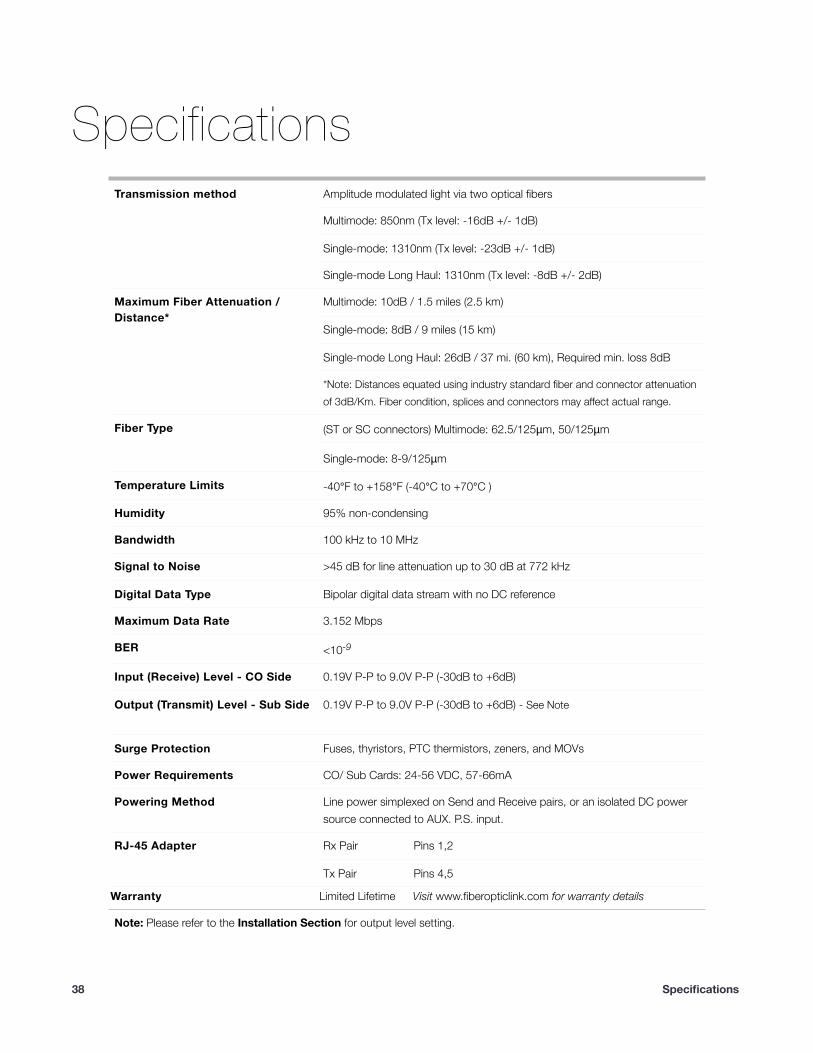
Specifications General Specifications
Transmission method Amplitude modulated light via two optical fibers
Multimode: 850nm (Tx level: -16dB +/- 1dB)
Single-mode: 1310nm (Tx level: -23dB +/- 1dB)
Single-mode Long Haul: 1310nm (Tx level: -8dB +/- 2dB)
Maximum Fiber Attenuation /Distance*
Multimode: 10dB / 1.5 miles (2.5 km)
Single-mode: 8dB / 9 miles (15 km)
Single-mode Long Haul: 26dB / 37 mi. (60 km), Required min. loss 8dB
*Note: Distances equated using industry standard fiber and connector attenuation of 3dB/Km. Fiber condition, splices and connectors may affect actual range.
Fiber Type (ST or SC connectors) Multimode: 62.5/125µm, 50/125µm
Single-mode: 8-9/125µm
Temperature Limits -40°F to +158°F (-40°C to +70°C )
Humidity 95% non-condensing
Bandwidth 100 kHz to 10 MHz
Signal to Noise >45 dB for line attenuation up to 30 dB at 772 kHz
Digital Data Type Bipolar digital data stream with no DC reference
Maximum Data Rate 3.152 Mbps
BER <10-9
Input (Receive) Level - CO Side 0.19V P-P to 9.0V P-P (-30dB to +6dB)
Output (Transmit) Level - Sub Side 0.19V P-P to 9.0V P-P (-30dB to +6dB) - See Note
Surge Protection Fuses, thyristors, PTC thermistors, zeners, and MOVs
Power Requirements CO/ Sub Cards: 24-56 VDC, 57-66mA
Powering Method Line power simplexed on Send and Receive pairs, or an isolated DC power source connected to AUX. P.S. input.
RJ-45 Adapter Rx Pair Pins 1,2
Tx Pair Pins 4,5
Warranty Limited Lifetime Visit www.fiberopticlink.com for warranty details
Note: Please refer to the Installation Section for output level setting.
� Specifications 38
Support Technical Support
Contact Information
�
Email: [email protected]/7 technical support: Toll Free 1-855-RLH-24X7
Toll Free 1-855-754-2497
Corporate Headquarters: RLH Industries, Inc. 936 N. Main Street Orange, CA 92867 USA
Phone: (714) 532-1672 Toll Free 1-800-877-1672 Toll Free 1-866-DO-FIBER
Fax: (714) 532-1885Email: [email protected] site: www.fiberopticlink.com
RLH Industries, Inc. 936 N. Main Street, Orange, CA 92867 USA T: (714) 532-1672 F: (714) 532-1885
Please contact your RLH sales representative for pricing and delivery information.
Specifications subject to change without notice.
Support �39
![FOM-E1/T1 · FOM-E1/T1 E1/T1 Fiber Optic Modem Option Wavelength Fiber Type Transmitter Type Typical Power Receiver Sensitivity Connector Typical Max. Range [nm] [µm] [dBm] [km]](https://img.pdfslide.net/doc/110x75/60bbc714da2ed42bab706100/fom-e1t1-fom-e1t1-e1t1-fiber-optic-modem-option-wavelength-fiber-type-transmitter.jpg)