Embed Size (px)
Citation preview

40 AND 100 GIGABIT ETHERNET CONSORTIUM
Annex 83E
100G CAUI-4 PMD Test Suite Version 1.1
Technical Document
Last Updated: May 10, 2016
40 and 100 Gigabit Ethernet Consortium 21 Madbury Road, Suite 100 Durham, NH 03824 University of New Hampshire Phone: (603) 862-0090 InterOperability Laboratory Fax: (603) 862-4181 https://www.iol.unh.edu/testing/ethernet/40and100gec/test-suites

The University of New Hampshire InterOperability Laboratory
TABLE OF CONTENTS
TABLE OF CONTENTS ..........................................................................................................2
MODIFICATION RECORD ....................................................................................................3
ACKNOWLEDGMENTS .........................................................................................................4
INTRODUCTION .....................................................................................................................5
GROUP 1: TRANSMITTER ELECTRICAL SIGNALING REQUIREMENTS ..................7
TEST 83E.1.1 – SIGNALING SPEED ............................................................................................8 TEST 83E.1.2 – COMMON MODE OUTPUT VOLTAGE ..................................................................9 TEST 83E.1.3 – DIFFERENTIAL OUTPUT AMPLITUDE ............................................................... 10 TEST 83E.1.4 – COMMON-MODE AC OUTPUT VOLTAGE RMS .................................................. 11 TEST 83E.1.5 – SINGLE ENDED OUTPUT VOLTAGE .................................................................. 12 TEST 83E.1.6 – TRANSITION TIME .......................................................................................... 13 TEST 83E.1.7 – TRANSMITTER EYE ......................................................................................... 14
GROUP 2: IMPEDANCE REQUIREMENTS ...................................................................... 15
TEST 83E.2.1 – DIFFERENTIAL OUTPUT RETURN LOSS ............................................................ 16 TEST 83E.2.2 – DIFFERENTIAL INPUT RETURN LOSS ............................................................... 17 TEST 83E.2.3 – COMMON TO DIFFERENTIAL OUTPUT RETURN LOSS ........................................ 18 TEST 83E.2.4 – DIFFERENTIAL TO COMMON MODE INPUT RETURN LOSS .................................. 19 TEST 83E.2.5 – MAXIMUM TERMINATION MISMATCH AT 1MHZ ............................................. 20
GROUP 3: RECIEVER ELECTRICAL SIGNALING REQUIREMENTS ........................ 21
TEST 83E.43.1 – STRESSED INPUT TEST .................................................................................. 22 APPENDIX I – TEST FIXTURES AND SETUPS ............................................................................. 24
40 and 100 Gigabit Consortium 2 Annex 83E –CAUI 4 PMD Test Suite v1.1

The University of New Hampshire InterOperability Laboratory
MODIFICATION RECORD December 1, 2014 Version 1.0
Michael Klempa: Preliminary release. First draft. Revision Publication Date Author(s) Comments 1.0 December 1. 2014 Michael Klempa Preliminary release. First draft. 1.1 May 10, 2016 Kathryn Dube Minor editorial updates to front cover
40 and 100 Gigabit Consortium 3 Annex 83E –CAUI 4 PMD Test Suite v1.1

The University of New Hampshire InterOperability Laboratory
ACKNOWLEDGMENTS
The University of New Hampshire would like to acknowledge the efforts of the following individuals in the development of this test suite.
Michael Klempa UNH InterOperability Laboratory Jeff Lapak UNH InterOperability Laboratory Curtis Donahue UNH InterOperability Laboratory
40 and 100 Gigabit Consortium 4 Annex 83E –CAUI 4 PMD Test Suite v1.1

The University of New Hampshire InterOperability Laboratory
INTRODUCTION The University of New Hampshire’s InterOperability Laboratory (IOL) is an institution designed to improve the interoperability of standards based products by providing an environment where a product can be tested against other implementations of a standard. This particular suite of tests has been developed to help implementers evaluate the functionality of the Physical Medium Dependent (PMD) sublayer of their 100G CAUI-4 products. These tests are designed to determine if a product conforms to specifications defined in Annex 83E of the IEEE Std 802.3bm. Successful completion of all tests contained in this suite does not guarantee that the tested device will operate with other devices. However, combined with satisfactory operation in the IOL’s interoperability test bed, these tests provide a reasonable level of confidence that the Device Under Test (DUT) will function properly in many 100G CAUI-4 environments. The tests contained in this document are organized in such a manner as to simplify the identification of information related to a test, and to facilitate in the actual testing process. Tests are organized into groups, primarily in order to reduce setup time in the lab environment, however the different groups typically also tend to focus on specific aspects of device functionality. A three-part numbering system is used to organize the tests, where the first number indicates the clause of the IEEE 802.3 standard on which the test suite is based. The second and third numbers indicate the test’s group number and test number within that group, respectively. This format allows for the addition of future tests to the appropriate groups without requiring the renumbering of the subsequent tests. The test definitions themselves are intended to provide a high-level description of the motivation, resources, procedures, and methodologies pertinent to each test. Specifically, each test description consists of the following sections: Purpose The purpose is a brief statement outlining what the test attempts to achieve. The test is written at the functional level. References This section specifies source material external to the test suite, including specific subclauses pertinent to the test definition, or any other references that might be helpful in understanding the test methodology and/or test results. External sources are always referenced by number when mentioned in the test description. Any other references not specified by number are stated with respect to the test suite document itself. Resource Requirements The requirements section specifies the test hardware and/or software needed to perform the test. This is generally expressed in terms of minimum requirements, however in some cases specific equipment manufacturer/model information may be provided.
40 and 100 Gigabit Consortium 5 Annex 83E –CAUI 4 PMD Test Suite v1.1

The University of New Hampshire InterOperability Laboratory
Last Modification This specifies the date of the last modification to this test. Discussion The discussion covers the assumptions made in the design or implementation of the test, as well as known limitations. Other items specific to the test are covered here. Test Setup The setup section describes the initial configuration of the test environment. Small changes in the configuration should not be included here, and are generally covered in the test procedure section, below. Test Procedure The procedure section of the test description contains the systematic instructions for carrying out the test. It provides a cookbook approach to testing, and may be interspersed with observable results. Observable Results This section lists the specific observables that can be examined by the tester in order to verify that the DUT is operating properly. When multiple values for an observable are possible, this section provides a short discussion on how to interpret them. The determination of a pass or fail outcome for a particular test is generally based on the successful (or unsuccessful) detection of a specific observable. Possible Problems This section contains a description of known issues with the test procedure, which may affect test results in certain situations. It may also refer the reader to test suite appendices and/or whitepapers that may provide more detail regarding these issues.
40 and 100 Gigabit Consortium 6 Annex 83E –CAUI 4 PMD Test Suite v1.1

The University of New Hampshire InterOperability Laboratory
GROUP 1: TRANSMITTER ELECTRICAL SIGNALING
REQUIREMENTS Overview: The tests defined in this section verify the transmitter’s electrical signaling characteristics of the Physical Medium Dependent (PMD) layer defined in Annex 83E of the IEEE Std. 802.3bm.
40 and 100 Gigabit Consortium 7 Annex 83E –CAUI 4 PMD Test Suite v1.1

The University of New Hampshire InterOperability Laboratory
Test 83E.1.1 – Signaling Speed Purpose: To verify that the baud rate of the DUT is within the conformance limits. References:
[1] IEEE Std. 802.3bm, Table 83E-1 – Transmitter Characteristics [2] IEEE Std. 802.3bj, subclause 93.8.1.1 – Transmitter Test fixture
Resource Requirements: See Appendix I Last Modification: December 1, 2014 Discussion: Reference [1] specifies the transmitter characteristics for 100G CAUI-4 devices. This specification includes conformance requirements for the signaling speed which states that the signaling speed should be 25.78125 Gbaud +/- 100 ppm per lane. This translates to 25.78125 Gbaud +/- 2.578125 Mbaud, with a nominal Unit Interval (UI) of 38.7878 ps. In this test, the signaling speed is measured while the DUT is connected to the test fixture defined in [2], or its functional equivalent. The signal being transmitted by the DUT may be any valid 100G CAUI-4 signal. Test Setup: See Appendix I Test Procedure:
1. Configure the DUT to send a valid signal or test pattern. 2. Connect the DUT’s transmitter to the DSO. 3. Measure the average TX signaling speed. 4. Repeat steps 1-3 for each transmit lane.
Observable Results:
a. The signaling speed should be within 25.78125 Gbaud +/- 100 ppm per lane Possible Problems: None.
40 and 100 Gigabit Consortium 8 Annex 83E –CAUI 4 PMD Test Suite v1.1

The University of New Hampshire InterOperability Laboratory
Test 83E.1.2 – Common Mode Output Voltage Purpose: To verify that the DC common mode output voltage of the DUT is within the conformance limits References:
[1] IEEE Std. 802.3bm, Table 83E-1 – Transmitter Characteristics [2] IEEE Std. 802.3bj, subclause 93.8.1.3 – Signal Levels [3] IEEE Std. 802.3bj, subclause 93.8.1.1 – Transmitter Test fixture
Resource Requirements: See Appendix I Last Modification: December 1, 2014 Discussion:
Reference [1] specifies the transmitter characteristics for 100G CAUI-4 devices. This specification includes conformance requirements for the common mode output voltage defined in [2].
In this test, the DC common mode output voltage is measured while the DUT is connected to the test fixture defined in [3], or its functional equivalent. The signal being transmitted by the DUT shall be PRBS9 as defined in [2]. Test Setup: See Appendix I Test Procedure:
1. Configure the DUT to send PRBS9. 2. Connect the DUT’s transmitter to the DSO. 3. Measure the common mode output voltage of SL<p> and SL<n>. 4. Repeat steps 1-3 for each transmit lane.
Observable Results:
a. The common mode output voltage should be between -0.3 V and 2.8 V with respect to the signal shield.
Possible Problems: None
40 and 100 Gigabit Consortium 9 Annex 83E –CAUI 4 PMD Test Suite v1.1
The University of New Hampshire InterOperability Laboratory
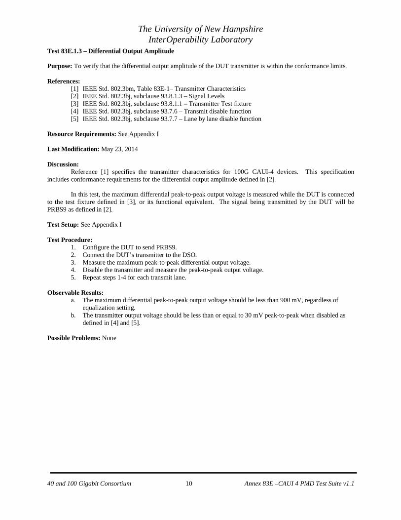
Test 83E.1.3 – Differential Output Amplitude Purpose: To verify that the differential output amplitude of the DUT transmitter is within the conformance limits. References:
[1] IEEE Std. 802.3bm, Table 83E-1– Transmitter Characteristics [2] IEEE Std. 802.3bj, subclause 93.8.1.3 – Signal Levels [3] IEEE Std. 802.3bj, subclause 93.8.1.1 – Transmitter Test fixture [4] IEEE Std. 802.3bj, subclause 93.7.6 – Transmit disable function [5] IEEE Std. 802.3bj, subclause 93.7.7 – Lane by lane disable function
Resource Requirements: See Appendix I Last Modification: May 23, 2014 Discussion:
Reference [1] specifies the transmitter characteristics for 100G CAUI-4 devices. This specification includes conformance requirements for the differential output amplitude defined in [2].
In this test, the maximum differential peak-to-peak output voltage is measured while the DUT is connected to the test fixture defined in [3], or its functional equivalent. The signal being transmitted by the DUT will be PRBS9 as defined in [2]. Test Setup: See Appendix I Test Procedure:
1. Configure the DUT to send PRBS9. 2. Connect the DUT’s transmitter to the DSO. 3. Measure the maximum peak-to-peak differential output voltage. 4. Disable the transmitter and measure the peak-to-peak output voltage. 5. Repeat steps 1-4 for each transmit lane.
Observable Results:
a. The maximum differential peak-to-peak output voltage should be less than 900 mV, regardless of equalization setting.
b. The transmitter output voltage should be less than or equal to 30 mV peak-to-peak when disabled as defined in [4] and [5].
Possible Problems: None
40 and 100 Gigabit Consortium 10 Annex 83E –CAUI 4 PMD Test Suite v1.1

The University of New Hampshire InterOperability Laboratory
Test 83E.1.4 – Common-mode AC output voltage RMS Purpose: To verify that the maximum AC common-mode output voltages are within the conformance limits. References:
[1] IEEE Std. 802.3bm, Table 83E-1 – Transmitter Characteristics [2] IEEE Std. 802.3bj, subclause 93.8.1.3 – Signal Levels [3] IEEE Std. 802.3bj, subclause 93.8.1.1 – Transmitter Test fixture
Resource Requirements: See Appendix I Last Modification: December 1, 2014 Discussion:
Reference [1] specifies the transmitter characteristics for 100G CAUI-4 devices. This specification includes conformance requirements for maximum output AC common-mode voltage defined in [2].
In this test, the differential amplitude is measured while the DUT is connected to the DSO. The common
mode voltage can be found by averaging the signal+ and signal- at any time. RMS AC common-mode voltage may be calculated by applying the histogram function over 1 UI to the common mode signal. The signal being transmitted by the DUT will be PRBS9 as defined in [2]. Test Setup: See Appendix I Test Procedure:
1. Configure the DUT to send PRBS9. 2. Connect the DUT’s transmitter to the DSO. 3. Apply a histogram function over 1 UI of the common mode signal. 5. Measure the common mode RMS amplitude. 6. Repeat steps 1-5 for each transmit lane.
Observable Results:
a. The maximum output AC common-mode voltage should be no greater than 17.5mV. Possible Problems: None
40 and 100 Gigabit Consortium 11 Annex 83E –CAUI 4 PMD Test Suite v1.1

The University of New Hampshire InterOperability Laboratory
Test 83E.1.5 – Single Ended Output Voltage Purpose: To verify that the single ended output voltage is within the conformance limits. References:
[1] IEEE Std. 802.3bm, Table 83E-1 – Transmitter Characteristics [2] IEEE Std. 802.3bm, subclause 83E.3.1.2 – Signal Levels [3] IEEE Std. 802.3bj, subclause 93.8.1.1 – Transmitter Test fixture
Resource Requirements: See Appendix I Last Modification: December 1, 2014 Discussion:
Reference [1] specifies the transmitter characteristics for 100G CAUI-4 devices. This specification includes conformance requirements for single ended output voltage defined in [2].
In this test, the single ended output voltage is measured while the DUT is connected to the test fixture
defined in [3], or its functional equivalent. The signal being transmitted by the DUT shall be PRBS9 as defined in [2]. Test Setup: See Appendix I Test Procedure:
1. Configure the DUT to send PRBS9. 2. Connect the DUT’s transmitter to the DSO. 3. Measure single ended output voltage of SL<p> and SL<n>. 4. Repeat steps 1-3 for all lanes
Observable Results:
a. The single ended output voltage shall have a minimum of -0.4V and a maximum of 3.3V Possible Problems: None
40 and 100 Gigabit Consortium 12 Annex 83E –CAUI 4 PMD Test Suite v1.1

The University of New Hampshire InterOperability Laboratory
Test 83E.1.6 – Transition Time Purpose: To verify that the DUT’s transition time is within the conformance limits References:
[1] IEEE Std. 802.3bm, Table 83E-1 – Transmitter Characteristics [2] IEEE Std. 802.3bm, subclause 83E.3.1.5 – Transition Time [3] IEEE Std. 802.3bj, Annex 86A.5.3.3 – Rise/Fall time
Resource Requirements: See Appendix I Last Modification: December 1, 2014 Discussion:
Reference [1] specifies the transmitter eye characteristics for 100G CAUI-4 devices. This specification includes conformance requirements for rising and falling edge transition times defined in [2]. In this test, the transition time is measured while the DUT is connected to the DSO. The transition times are to be measured at the 20% and 80% levels as defined in [3]. Reference [3] also requires that the measurement be done using the square wave test pattern [3], with no equalization [3] and a run of at least eight consecutive ones. Test Setup: See Appendix I Test Procedure:
1. Configure the DUT so that it is sourcing a square pattern with no equalization. 2. Connect the DUT’s transmitter to the DSO. 3. Capture a run of at least right consecutive ones. 4. Measure the rising and falling edge transition times. 5. Repeat steps 1-5 for each transmit lane.
Observable Results:
a. The rising and falling edge transition times value should be greater than or equal to 10 ps. Possible Problems: None
40 and 100 Gigabit Consortium 13 Annex 83E –CAUI 4 PMD Test Suite v1.1

The University of New Hampshire InterOperability Laboratory
Test 83E.1.7 – Transmitter Eye Purpose: To verify that the DUT’s transmit jitter is within conformance limits References:
[1] IEEE Std. 802.3bm, Table 83E-1 – Transmitter Characteristics [2] IEEE Std. 802.3bm, subclause 83E.3.1.6 – Host output eye width and eye height [3] IEEE Std. 802.3bm, subclause 83E.4.2 – Eye width and eye height measurement method [4] IEEE Std. 802.3bm, Figure 83E-9– Host output eye width and eye height setup
Resource Requirements: See Appendix I Last Modification: December 1, 2014 Discussion:
Reference [1] specifies the transmitter eye characteristics for 100G CAUI-4 devices. This specification includes conformance requirements for the transmitter eye defined in [2]. In this test, the transmitter eye width is measured by leveraging the Dual-Dirac jitter model to estimate random jitter on a cumulative density function (CDF) created from a differential equalized signal. The DUT is instructed to transmit Pattern 4, and there should be sufficient samples to allow for a CDF to a probability of 10-6 without extrapolation. The CDF for the left and right edges of the eye diagram are linear fit to yield the random jitter for the left and right edges (RJR, RJL), which then uses equation 83E-7 to extrapolate the eye width from 10-6 probability to the desired 10-15 probability:
𝐸𝐸𝐸𝐸15 = 𝐸𝐸𝐸𝐸6− 3.19 ∗ (𝑅𝑅𝑅𝑅𝑅𝑅 + 𝑅𝑅𝑅𝑅𝑅𝑅) (83𝐸𝐸 − 7)
The transmitter eye height is found by finding the central 5% of the signal at both logic 1 and logic 0. A CDF is created for each level, which are linear fit in Q-scale over the range of probabilities of 10-4 and 10-6 which yield relative noise 1 (RN1) and relative noise 0 (RN0). Equation 83E-8 is used to extrapolate the eye height from 10-6 probability to the desired 10-15 probability:
𝐸𝐸𝐸𝐸15 = 𝐸𝐸𝐸𝐸6− 3.19 ∗ (𝑅𝑅𝑅𝑅0 + 𝑅𝑅𝑅𝑅1) (83𝐸𝐸 − 8) Test Setup: See Appendix I Test Procedure:
1. Configure a receiver to specifications listed in [3] and connect to DUT. 2. Acquire the recommended CTLE settings from receiver. 3. Configure the DUT so that it is sourcing pattern 4 with equalization. 4. Connect the DUT’s transmitter to the DSO. 5. Capture at least 4 million samples. 6. Calculate EW15 and EH15 following the procedure in [3]. 7. Repeat steps 1-6 for each transmit lane. 8. Repeat steps 3-7 for with CTLE values 1dB higher than recommended by host. 9. Repeat steps 3-7 for with CTLE values 1dB lower than recommended by host.
Observable Results:
a. The eye width shall be at least 0.46 UI. b. The eye height shall be at least 95 mV for case A (recommended equalization), and 80mV for case B
(+/- 1dB of equalization to CTLE). Possible Problems: None
40 and 100 Gigabit Consortium 14 Annex 83E –CAUI 4 PMD Test Suite v1.1

The University of New Hampshire InterOperability Laboratory
GROUP 2: IMPEDANCE REQUIREMENTS
Overview: The tests defined in this section verify the impedance characteristics of the Physical Medium Dependent (PMD) layer defined in Annex 83E of the IEEE Std. 802.3bm.
40 and 100 Gigabit Consortium 15 Annex 83E –CAUI 4 PMD Test Suite v1.1

The University of New Hampshire InterOperability Laboratory
Test 83E.2.1 – Differential Output Return Loss Purpose: To verify that the differential output return loss of the DUT is within the conformance limits References:
[1] IEEE Std. 802.3bm., Table 83E-1 – Transmitter Characteristics [2] IEEE Std. 802.3bm., subclause 83E.3.1.3 – Differential output return loss
Resource Requirements: See Appendix I Last Modification: December 1, 2014 Discussion:
Reference [1] specifies the transmitter characteristics for 100G CAUI-4 devices. This specification includes conformance requirements for the differential output return loss, which are specified in [2].
For the purpose of this test, the differential output return loss is defined as the magnitude of the reflection coefficient expressed in decibels of the DUT’s transmitter. The reflection coefficient is the ratio of the voltage in the reflected wave to the voltage in the incident wave. The differential output return loss of the driver should exceed (83E-2). The reference impedance for differential return loss measurements shall be 100 Ω.
𝑅𝑅𝑅𝑅𝑅𝑅𝑅𝑅𝑅𝑅𝑅𝑅_𝑙𝑙𝑙𝑙𝑙𝑙𝑙𝑙(𝑓𝑓) ≥ 9.5− 0.37𝑓𝑓 0.01 ≤ 𝑓𝑓 ≤ 84.75− 7.4𝑙𝑙𝑙𝑙𝑙𝑙10(𝑓𝑓) 8 ≤ 𝑓𝑓 ≤ 19 (𝑑𝑑𝑑𝑑) (83𝐸𝐸 − 2)
Test Setup: See Appendix I Test Procedure:
1. Calibrate the VNA to remove the effects of the coaxial cables. 2. Connect the DUT’s transmitter to the VNA. 3. Measure the differential output return loss of the DUT. 4. Repeat steps 1-3 for each transmit lane.
Observable Results:
a. The differential output return loss should exceed the limits described by (83E-2). Possible Problems: None
40 and 100 Gigabit Consortium 16 Annex 83E –CAUI 4 PMD Test Suite v1.1

The University of New Hampshire InterOperability Laboratory
Test 83E.2.2 – Differential Input Return Loss Purpose: To verify that the differential output return loss of the DUT is within the conformance limits References:
[1] IEEE Std. 802.3bm., Table 83E-4 – Receiver Characteristics [2] IEEE Std. 802.3bm., subclause 83E.3.3.1 – Differential input return loss
Resource Requirements: See Appendix I Last Modification: December 1, 2014 Discussion:
Reference [1] specifies the transmitter characteristics for 100G CAUI-4 devices. This specification includes conformance requirements for the differential output return loss, which are specified in [2].
For the purpose of this test, the differential input return loss is defined as the magnitude of the reflection coefficient expressed in decibels of the DUT’s transmitter. The reflection coefficient is the ratio of the voltage in the reflected wave to the voltage in the incident wave. The differential input return loss of the driver should exceed (83E-5). The reference impedance for differential return loss measurements shall be 100 Ω.
𝑅𝑅𝑅𝑅𝑅𝑅𝑅𝑅𝑅𝑅𝑅𝑅_𝑙𝑙𝑙𝑙𝑙𝑙𝑙𝑙(𝑓𝑓) ≥ 9.5− 0.37𝑓𝑓 0.01 ≤ 𝑓𝑓 ≤ 8
4.75− 7.4𝑙𝑙𝑙𝑙𝑙𝑙10(𝑓𝑓
14) 8 ≤ 𝑓𝑓 ≤ 19 (𝑑𝑑𝑑𝑑) (83𝐸𝐸 − 5)
Test Setup: See Appendix I Test Procedure:
1. Calibrate the VNA to remove the effects of the coaxial cables. 2. Connect the DUT’s transmitter to the VNA. 3. Measure the differential input return loss of the DUT. 4. Repeat steps 1-3 for each transmit lane.
Observable Results:
a. The differential input return loss should exceed the limits described by (83E-5). Possible Problems: None
40 and 100 Gigabit Consortium 17 Annex 83E –CAUI 4 PMD Test Suite v1.1

The University of New Hampshire InterOperability Laboratory
Test 83E.2.3 – Common to Differential Output Return Loss Purpose: To verify that the common mode output return loss of the DUT is within the conformance limits References:
[1] IEEE Std. 802.3bm., Table 83E-1 – Transmitter Characteristics [2] IEEE Std. 802.3bm., subclause 83E.3.1.3 – Output return loss
Resource Requirements: See Appendix I Last Modification: December 1, 2014 Discussion:
Reference [1] specifies the transmitter characteristics for 100G CAUI-4 devices. This specification includes conformance requirements for the common to differential output return loss, which are specified in [2].
For the purpose of this test, the differential to common output return loss is defined as the magnitude of the reflection coefficient expressed in decibels of the DUT’s receiver. The reflection coefficient is the ratio of the voltage in the reflected wave to the voltage in the incident wave. The differential to common mode return loss of the driver should exceed (93-4).
𝑅𝑅𝑅𝑅𝑅𝑅𝑅𝑅𝑅𝑅𝑅𝑅_𝑙𝑙𝑙𝑙𝑙𝑙𝑙𝑙(𝑓𝑓) ≥ 22− 20
𝑓𝑓25.78 0.01 ≤ 𝑓𝑓 ≤ 12.89
15 − 6𝑓𝑓
25.7812.89 ≤ 𝑓𝑓 ≤ 19
(𝑑𝑑𝑑𝑑) (83𝐸𝐸 − 3)
Test Setup: See Appendix I Test Procedure:
1. Calibrate the VNA to remove the effects of the coaxial cables. 2. Connect the DUT’s receiver to the VNA. 3. Measure the common to differential output return loss of the DUT. 4. Repeat steps 1-3 for each transmit lane.
Observable Results:
a. The differential to common mode return loss should exceed the limits described by (83E-3). Possible Problems: None
40 and 100 Gigabit Consortium 18 Annex 83E –CAUI 4 PMD Test Suite v1.1

The University of New Hampshire InterOperability Laboratory
Test 83E.2.4 – Differential to Common mode input Return Loss Purpose: To verify that the differential to common mode input return loss of the DUT is within the conformance limits References:
[1] IEEE Std. 802.3bm., Table 83E-4– Receiver Characteristics [2] IEEE Std. 802.3bm., subclause 83E.3.3.1 – Input return loss
Resource Requirements: See Appendix I Last Modification: December 1, 2014 Discussion:
Reference [1] specifies the transmitter characteristics for 100G CAUI-4 devices. This specification includes conformance requirements for the differential to common mode input return loss, which are specified in [2].
For the purpose of this test, the differential to common mode input return loss is defined as the magnitude of the reflection coefficient expressed in decibels of the DUT’s receiver. The reflection coefficient is the ratio of the voltage in the reflected wave to the voltage in the incident wave. The differential to common mode input return loss of the driver should exceed (83E-6).
𝑅𝑅𝑅𝑅𝑅𝑅𝑅𝑅𝑅𝑅𝑅𝑅_𝑙𝑙𝑙𝑙𝑙𝑙𝑙𝑙(𝑓𝑓) ≥ 22− 20
𝑓𝑓25.78 0.01 ≤ 𝑓𝑓 ≤ 12.89
15 − 6𝑓𝑓
25.7812.89 ≤ 𝑓𝑓 ≤ 19
(𝑑𝑑𝑑𝑑) (83𝐸𝐸 − 6)
Test Setup: See Appendix I Test Procedure:
1. Calibrate the VNA to remove the effects of the coaxial cables. 2. Connect the DUT’s receiver to the VNA. 3. Measure the differential to common mode input return loss of the DUT. 4. Repeat steps 1-3 for each transmit lane.
Observable Results:
a. The differential to common mode return loss should exceed the limits described by (83E-6). Possible Problems: None
40 and 100 Gigabit Consortium 19 Annex 83E –CAUI 4 PMD Test Suite v1.1

The University of New Hampshire InterOperability Laboratory
Test 83E.2.5 – Maximum Termination Mismatch at 1MHz Purpose: To verify that the termination mismatch of the DUT is within the conformance limits References:
[1] IEEE Std. 802.3bm., Table 83E-1 – Transmitter Characteristics [2] IEEE Std. 802.3bm., subclause 83E.3.1.4 – Differential termination mismatch [3] IEEE Std. 802.3-2012, subclause 86A.5.3.2 – Termination mismatch
Resource Requirements: See Appendix I Last Modification: December 1, 2014 Discussion:
Reference [1] specifies the transmitter characteristics for 100G CAUI-4 devices. This specification includes conformance requirements for the differential termination mismatch, which is specified in [2] and [3]. In this test, the termination mismatch can be measured by applying a low frequency test tone to the differential inputs. The test frequency must be high enough to overcome the high pass effects of any AC coupling capacitors. Once the impedance of both inputs is found, use Equation 86A -10 to find the mismatch:
𝛥𝛥𝛥𝛥𝛥𝛥 = 2 ∗|𝛥𝛥𝑍𝑍 − 𝛥𝛥𝑅𝑅|𝛥𝛥𝑍𝑍 − 𝛥𝛥𝑅𝑅
∗ 100 (%) (86𝐴𝐴 − 10)
Test Setup: See Appendix I Test Procedure:
1. Calibrate the VNA to remove the effects of the coaxial cables. 2. Connect the DUT’s transmitter to the VNA. 3. Configure the DUT so that it is sourcing low frequency signaling [3]. 4. Connect the DUT’s positive transmitter to the VNA 5. Observe the Impedance for the positive channel. 6. Repeat steps 3 and 4 for the negative channel 7. Using the values from the positive and negative impedances compute the termination mismatch with
equation 86A - 10. 8. Repeat steps 1-3 for each transmit lane.
Observable Results:
a. The termination mismatch shall be less than 10% Possible Problems: None
40 and 100 Gigabit Consortium 20 Annex 83E –CAUI 4 PMD Test Suite v1.1

The University of New Hampshire InterOperability Laboratory
GROUP 3: RECIEVER ELECTRICAL SIGNALING REQUIREMENTS
Overview: The tests defined in this section verify the receiver’s electrical signaling characteristics of the Physical Medium Dependent (PMD) layer defined in Annex 83E of the IEEE Std. 802.3bm.
40 and 100 Gigabit Consortium 21 Annex 83E –CAUI 4 PMD Test Suite v1.1

The University of New Hampshire InterOperability Laboratory
Test 83E.43.1 – Stressed Input Test Purpose: To verify that the bit error ratio (BER) of the DUT’s receiver is within the conformance limits while communicating over a lossy channel with coupled interference. References:
[1] IEEE Std. 802.3bm, Table 83E- 4 Host input characteristics [2] IEEE Std. 802.3bm, subclause 83E.3.3.2 – Host stressed input parameters [3] IEEE Std. 802.3bm, subclause 83E.3.3.2.1 – Host stressed input test procedure [4] IEEE Std. 802.3bm, Figure 83E-14 – Host stressed input summary [5] IEEE Std. 802.3bj, Annex 93A.2 - Test channel calibration [6] IEEE Std. 802.3bm, Table 83E-6 - COM parameter values
Resource Requirements: See Appendix I Last Modification: May 23, 2014 Discussion:
Reference [1] specifies the receiver tolerance characteristics for 100G CAUI-4 devices. A major problem in the communication of multi-channel transceivers is interference. The interfering signal can come from a variety of sources including: a) Crosstalk from other data channels running the same kind of signals as the channel of interest. This type of interference is usually subdivided into:1) Far-end crosstalk (FEXT) coming from data traveling in the same general direction as the channel of interest.2) Near-end crosstalk (NEXT) originating from a channel with a transmitter near the receiver of the channel of interest. b) Self interference caused by reflections due to impedance discontinuities, stubs, etc. This is a form of intersymbol interference (ISI) that is beyond what a reasonable equalizer can compensate. c) Alien crosstalk which is defined to be interference from unrelated sources such as clocks, other kinds of data, power supply noise, etc. For the channel to work, the receiver must be able to extract correct data from the lossy channel in the presences of interference. The ability of the receiver to extract data in the presence of interference is an important characteristic of the receiver and needs to be measured. This ability is called interference tolerance.
In this test, BER is measured while the DUT is subjected to an input victim signal with far-end crosstalk disturber interference as specified in [3]. The DUT’s transmitter taps are set via management to provide the lowest BER and sinusoidal jitter is added to the test transmitter via a modulated clock source. Reference [4] specifies four sets of test values which describe the setup parameters for the test. The test channel will be calibrated using COM as described in [5] with the parameters as described in [6]. Test Setup: See Appendix I Test Procedure:
1. Configure the victim, far end and near end pattern generator output to transmit a jittered PRBS9 waveform
2. Connect the lane under test’s transmitter to an error detector. 3. Enable an externally facing loopback on the DUT. 4. Transmit at least 3x1012 bits from the victim pattern generator and calculate the BER from the number
of errors on the error detector. 5. Repeat steps 1-4 for all test values in [4]. 6. Repeat steps 1-5 with signaling speed of 25.78125 Gbd - 100ppm and 25.78125 Gbd + 100ppm. 7. Repeat steps 1-8 for each receive lane.
Observable Results:
a. The receiver shall operate with a BER of 10-15 or better Possible Problems: None
40 and 100 Gigabit Consortium 22 Annex 83E –CAUI 4 PMD Test Suite v1.1

The University of New Hampshire InterOperability Laboratory
APPENDICES Overview:
Test suite appendices are intended to provide additional low-level technical detail pertinent to specific tests contained in this test suite. These appendices often cover topics that are outside of the scope of the standard, and are specific to the methodologies used for performing the measurements in this test suite. Appendix topics may also include discussion regarding a specific interpretation of the standard (for the purposes of this test suite), for cases where a particular specification may appear unclear or otherwise open to multiple interpretations. Scope:
Test suite appendices are considered informative supplements, and pertain solely to the test definitions and procedures contained in this test suite.
40 and 100 Gigabit Consortium 23 Annex 83E –CAUI 4 PMD Test Suite v1.1

The University of New Hampshire InterOperability Laboratory
Appendix I – Test Fixtures and Setups Purpose: To specify the test equipment and setup used to test all electrical characteristic as well as waveform characteristics in this test suite. Last Modification: May 23, 2014 Equipment List:
1. Digital Storage Oscilloscope, 35 GHz bandwidth (minimum) 2. Vector Network Analyzer, capable of measuring up to19 GHz (minimum) 3. Bit Error Rate Tester (BERT) 4. 50Ω matched coax cables 5. Host compliance board (HCB)
83E.I – 1: Setup used for Group 1: Transmitter Electrical testing
83E.I – 2: Setup used for Group 3: Impedance Requirements testing
40 and 100 Gigabit Consortium 24 Annex 83E –CAUI 4 PMD Test Suite v1.1

The University of New Hampshire InterOperability Laboratory
83E.I – 3: Setup used for Group 4: Receiver Electrical Requirements testing
40 and 100 Gigabit Consortium 25 Annex 83E –CAUI 4 PMD Test Suite v1.1