Embed Size (px)
Citation preview
AC
-D
C
Specification
400-2500 Watts
• Configurable for Fast Time to Market
• SEMI F47 Compliant
• Flexible Series & Parallel Capability
• -20 °C Operation
• Extra Power Available at High Line
• Optional Fan Speed Control
• 3 Year Warranty
f leXPower Series
InputInput Voltage • 85-264 VAC (120-370 VDC). Full power at
90 VAC, derate by 10% at 85 VAC. 3 phaseinput is available, see 3 phase fleXPowerdatasheet.
Input Frequency • 47-63 Hz, 400 Hz (all specifications met at400 Hz, except leakage current)
Input Current(1) • X4: 5.33 A at 115 VAC, 2.67 A at 230 VACX5: 6.67 A at 115 VAC, 3.33 A at 230 VACX7: 9.33 A at 115 VAC, 4.67 A at 230 VACX9: 12.0 A at 115 VAC, 6.00 A at 230 VACX10: 13.3 A at 115 VAC, 6.67 A at 230 VACX15: 20 A at 115 VAC, 10 A at 230 VAC
Inrush Current(1) • X4, X5, X7: <20 A, X9/X10: <40 A, X15: <60 A, cold start at 25 °C
Power Factor • 0.99 typical at 115 VAC & 230 VAC full loadEarth Leakage Current(1) • X models: <1.5 mA at 264 VAC, 50 Hz
XM7-10: <200 µA at 264 VAC, 50 HzXM15: <300 µA at 115 VAC 60 Hz, <400 µA at 264 VAC 50 Hz
Input Protection • X4-7/XM4-7: T12 A/250 V, X9/XM9: T15 A/250 V, X10/XM10: T20 A/250 V, X15/XM15: T30 A/250 V, internal fuse in lineand neutral
OutputOutput Power • See tableOutput Voltage • See tableOutput Voltage Trim • 3.3 V outputs ±6%, others ±10% Minimum Load • No min load required for 2 slot, 3 slot or 4
slot single output modules on 6x dualoutput models. 5x dual outputs require10% load on V1 to meet specifiedregulation on V2
Start Up Delay • 2 s typicalHold Up Time • 20 ms at 90 VAC input & full output loadLine Regulation • <0.1%Load Regulation • <1.0%Ripple & Noise • 50 mV or 1% pk-pk at 20 MHz bandwidth,
whichever is greater. 6E module has 1.5%on V1 and V2. 6N module has 1.5% on V1and 3% on V2
Overvoltage Protection • 115-130% Vnom, 115-140% Vnom for 6Eand 6N modules
Overtemperature • 115 °C measured internally, auto resetting ProtectionOverload Protection • 110-140% for 2x, 3x and 4x modules
110-150% for 1x modules110-150% on V1 and 110-200% on V2 of5x modules110-200% on V1 and V2 of 6x modules
Short Circuit Protection • Continuous trip & restart (hiccup mode)Temperature • 0.03%/°CCoefficientRemote Sense • Compensates for up to 0.5 V dropEnable/Inhibit • See signals pageCurrent Share • See signals pageHousekeeping Voltage • 5 V/1 A from each chassis
xppower.com
GeneralEfficiency • Up to 89%Isolation • 4000 VAC Input to Output 2 x MOPP,
1500 VAC Input to Ground 1 x MOPP,250 VDC Output to Ground
Switching Frequency • 60 kHz typ PFC, 200 kHz typ modulesSignals • See signals pageMTBF • 225 kHrs typ to MIL-HDBK-217F at 25 °C, GB
EnvironmentalOperating Temperature • -20 °C to +70 °C. For operation above
+50 °C, derate linearly to 50% load at +70 °C. Reverse air option derate from +40 °C to half load at +60 °C
Cooling • Forced air cooling (via field-replaceableinternal fan). Fan speed control optional
Operating Humidity • 5-95% RH, non-condensingStorage Temperature • -40 °C to +85 °COperating Altitude • 3000 m at full specificationShock • MIL STD-810 Method 516.4 Procedure 1,
30 g, half sine, 6 axesVibration • MIL STD-810 Method 514.4 Procedure 1,
1 g rms, 5-500 Hz, 3 axes
EMC & SafetyEmissions • X version: EN55022 (CISPR22) Class B
conducted XM version: EN55011 (CISPR 11) Class Aconducted
Immunity • EN60601-1-2, EN61204-3Harmonic Currents • EN61000-3-2, Class AVoltage Flicker • EN61000-3-3ESD Immunity • EN61000-4-2, level 4 Perf Criteria ARadiated Immunity • EN61000-4-3, 10 V/m Perf Criteria AEFT/Burst • EN61000-4-4, level 3 Perf Criteria ASurge • EN61000-4-5, installation class 3,
Perf Criteria A, SEMI F47Conducted Immunity • EN61000-4-6, level 3 Perf Criteria ADips and Interruptions • EN61000-4-11 , 30% 10 ms, 60% 100 ms,
100% 5000 ms, Perf Criteria A, B, BEN60601-1, 30% 500 ms, 60% 100 ms,100% 10 ms, 100% 5000 ms,Perf Criteria A, A (with 60% load), A, B
Safety Approvals • EN60601-1, ANSI/AAMI ES60601-1,CSA22.2 No.60601-1 per cUL, Including RiskManagement XM Models, EN60950, UL60950X Models
Notes1. Current specifications double for DD chassis versions.
(Low leakage for EN60601-1-2 available as modified standard, contact sales)

AC
-D
C
fleXPowerConfiguration - Model Number Construction
Model Sector
Vinput
Slots115 V 230 V
Pnom Ppk* Pnom Ppk*
X4 Industrial 400 W 800 W 600 W 1200 W 10XM4 Medical 400 W 800 W 600 W 1200 W 10X5 Industrial 500 W 800 W 700 W 1200 W 10XM5 Medical 500 W 800 W 700 W 1200 W 10X7 Industrial 700 W 800 W 900 W 1200 W 10XM7 Medical 700 W 800 W 900 W 1200 W 10X9 Industrial 900 W 1100 W 1100 W 1500 W 12XM9 Medical 900 W 1100 W 1100 W 1500 W 12X10 Industrial 1000 W 1300 W 1200 W 1600 W 14XM10 Medical 1000 W 1300 W 1200 W 1600 W 14
The fleXPower range allows for simple configuration of a custom modular power supply with up to twenty outputs. The chassisconsists of either ten, twelve, fourteen or twenty slots, and modules are either two, three or four slots wide. Please refer to next pagefor specific X15 configuration information.
Dual Output - Module Voltage/Current RatingOutput 1 Output 2 Slots CodeVoltage Current Voltage Current
5.0 V 10.0 A 5.0 V 10.0 A 2 5A5.0 V 10.0 A 3.3 V 10.0 A 2 5B12.0 V 10.0 A 12.0 V 8.0 A 2 5D15.0 V 8.0 A 15.0 V 6.0 A 2 5E15.0 V 8.0 A 15.0 V 6.0 A 2 6E*15.0 V 8.0 A 12.0 V 8.0 A 2 5F12.0 V 10.0 A 5.0 V 10.0 A 2 5G12.0 V 10.0 A 3.3 V 10.0 A 2 5H12.0 V 10.0 A 2.0 V 10.0 A 2 5J15.0 V 10.0 A 5.0 V 10.0 A 2 5K15.0 V 10.0 A 3.3 V 10.0 A 2 5L15.0 V 10.0 A 2.0 V 10.0 A 2 5M24.0 V 6.0 A 5.0 V 10.0 A 2 5N24.0 V 6.0 A 5.0 V 10.0 A 2 6N*24.0 V 6.0 A 3.3 V 10.0 A 2 5P24.0 V 6.0 A 2.0 V 10.0 A 2 5Q
Step 1To configure your fleXPower unit, select the requiredoutput power and application type. fleXPower chassisare available in multiple power formats.
Step 2FleXPower can accommodate up to ten modules,resulting in an extensive range of output combinations.However, as all modules are designed to fit across either2, 3 or 4 slots in the chassis, configuration is verysimple. Select the appropriate modules for your outputrequirements, ensurig that all modules will fit in thechassis. First, insert 4 series modules, ordered lowestvoltage to highest. Next in order, insert 3 seriesmodules, ordered lowest voltage highest. Follow with 2series, then 5 series dual output, ordered alphabeticallya-z. Then 1 series, ordered lowest voltage to highest.
Step 3Add any required options. These are grouped into threetypes; parallel options, series options and other options.The standard signal set for each chassis includes GlobalInhibit, Global DC OK and Global AC OK, each havinglogic 0 operation. Optionally a logic 1 operating version ofeach is available along with reverse air flow. Also availableis a fan speed control option, which is availableseparately or combined with previously listed options.
Parallel Option CodesCode Description00 No parallel required12 Modules 1 & 213 Modules 1 to 314 Modules 1 to 423 Modules 2 & 324 Modules 2 to 425 Modules 2 to 534 Modules 3 & 435 Modules 3 to 540 Modules 1 & 2, 3 & 4
Series Option CodesCode Description00 No series required12 Modules 1 & 213 Modules 1 to 323 Modules 2 & 324 Modules 2 to 440 Modules 1 & 2, 3 & 4
OUTPUT MODULES 1-5 (1-6: 900 W chassis/ 1-7: 1000 W chassis)
X7 - 700 W industrial chassis, 10 module slots available.3C - 3.3 V @ 60.0 A. Three slot width module.3L - 15.0 V @ 20.0 A. Three slot width module.2C - 3.3 V @ 40.0 A. Two slot width module.00 - No parallel option.00 - No series option.16 - Fan speed control card.
CHASSIS OPTIONS
P P S S + +X X X X - -
Example
MOD.1 MOD.2 MOD.3 MOD.4 MOD.5 MOD.7MOD.6
Note: Total power for dual output module must not exceed 175 W max. 6x modules do not need minimum load on output 1 for regulation
Other Option CodesCode Description01 Reverse Air02 Global Enable - Logic 103 Option 01 & 0204 Global DC OK - Logic 105 Option 01 & 0406 Option 02 & 0407 Option 01, 02 & 0408 Global AC OK - Logic 109 Option 01 & 0810 Option 02 & 0811 Option 01, 02 & 0812 Option 04 & 0813 Option 01, 04 & 0814 Option 02, 04 & 0815 Option 01, 02, 04 & 0816 Fan Speed Control17 Option 01 & 1618 Option 02 & 1619 Option 04 & 1620 Option 08 & 1621 Option 01, 02 & 1622 Option 01, 04 & 1623 Option 01, 08 & 1624 Option 02, 04 & 1625 Option 02, 08 & 1626 Option 04, 08 & 1627 Option 01, 02, 04 & 1628 Option 01, 02, 08 & 1629 Option 02, 04, 08 & 1630 Option 01, 02, 04, 08 & 16
X7-3C3L2C-000016
Note: Peak power available for 10 seconds with 35% dutycycle.
Note: 1. Fancard options 16-30 willoccupy 2 slots. See mechanicaldrawing.
Single Output - Module Voltage/Current RatingVoltage Current Ipk Power Ppk Slots Code3.3 V 20.0 A n/a 66 W n/a 2 1C3.3 V 40.0 A n/a 132 W n/a 2 2C3.3 V 60.0 A n/a 198 W n/a 3 3C5.0 V 20.0 A n/a 100 W n/a 2 1D5.0 V 40.0 A n/a 200 W n/a 2 2D5.0 V 60.0 A n/a 300 W n/a 3 3D8.0 V 25.0 A n/a 200 W n/a 2 2H10.0 V 20.0 A n/a 200 W n/a 2 2I10.0 V 30.0 A n/a 300 W n/a 3 3I12.0 V 8.50 A n/a 102 W n/a 2 1J12.0 V 17.0 A n/a 204 W n/a 2 2J12.0 V 25.0 A n/a 300 W n/a 3 3J12.0 V 62.5 A n/a 750 W n/a 4 4J15.0 V 7.00 A n/a 105 W n/a 2 1L15.0 V 14.0 A n/a 210 W n/a 2 2L15.0 V 20.0 A n/a 300 W n/a 3 3L15.0 V 50.0 A n/a 750 W n/a 4 4L18.0 V 16.7 A n/a 300 W n/a 3 3N24.0 V 5.00 A n/a 120 W n/a 2 1P24.0 V 10.5 A n/a 252 W n/a 2 2P24.0 V 17.0 A n/a 408 W n/a 3 3P24.0 V 31.5 A n/a 750 W n/a 4 4P24.0 V 5.00 A 10.0 A 120 W 240 W 2 1R(1)
24.0 V 10.5 A 21.0 A 252 W 504 W 2 2R(1)
24.0 V 17.0 A 34.0 A 408 W 816 W 3 3R(1)
28.0 V 4.50 A n/a 126 W n/a 2 1Q28.0 V 9.00 A n/a 252 W n/a 2 2Q28.0 V 14.0 A n/a 392 W n/a 3 3Q28.0 V 26.8 A n/a 750 W n/a 4 4Q30.0 V 8.4 A n/a 252 W n/a 2 2S30.0 V 13.5 A n/a 405 W n/a 3 3S36.0 V 3.50 A n/a 126 W n/a 2 1U36.0 V 7.00 A n/a 252 W n/a 2 2U36.0 V 11.0 A n/a 396 W n/a 3 3U36.0 V 21.0 A n/a 750 W n/a 4 4U42.0 V 9.05 A n/a 400 W n/a 3 3V48.0 V 2.50 A n/a 120 W n/a 2 1W48.0 V 5.20 A n/a 249 W n/a 2 2W48.0 V 8.50 A n/a 408 W n/a 3 3W48.0 V 15.7 A n/a 750 W n/a 4 4W60.0 V 2.00 A n/a 120 W n/a 2 1Y60.0 V 4.20 A n/a 252 W n/a 2 2Y60.0 V 7.00 A n/a 420 W n/a 3 3Y60.0 V 12.5 A n/a 750 W n/a 4 4Y
1. Peak power available for 10 seconds with 35% dutycycle, if peak power rating is exceeded output may latch,recycle input to reset.

AC
-D
C fleXPowerX15 Configuration Rules
Model Sector
Vinput
Slots115 V 230 V
Max Power Max Power
X15 Industrial 1500 W 2500 W 20XM15 Medical 1500 W 2500 W 20
Step 1To configure your fleXPower unit, select the requiredoutput power and application type. fleXPower chassisare available in multiple power formats.
Step 2FleXPower can accommodate up to ten modules,resulting in an extensive range of output combinations.However, as all modules are designed to fit across either2, 3 or 4 slots in the chassis, configuration is verysimple. Select the appropriate modules for your outputrequirements, ensurig that all modules will fit in thechassis. First, insert 4 series modules, ordered lowestvoltage to highest. Next in order, insert 3 seriesmodules, ordered lowest voltage highest. Follow with 2series, then 5 series dual output, ordered alphabeticallya-z. Then 1 series, ordered lowest voltage to highest.
Step 3Add any required options. These are grouped into threetypes; parallel options, series options and other options.The standard signal set for each chassis includesGlobal Inhibit, Global DC OK and Global AC OK, eachhaving logic 0 operation. Optionally a logic 1 operatingversion of each is available along with reverse air flow.Also available is a fan speed control option, which isavailable separately or combined with previously listedoptions.
Parallel Option CodesCode Description00 No parallel required12 Modules 1 & 213 Modules 1 to 314 Modules 1 to 423 Modules 2 & 324 Modules 2 to 425 Modules 2 to 534 Modules 3 & 435 Modules 3 to 540 Modules 1 & 2, 3 & 4
Series Option CodesCode Description00 No series required12 Modules 1 & 213 Modules 1 to 323 Modules 2 & 324 Modules 2 to 440 Modules 1 & 2, 3 & 4
Vertical Parallel Option CodeCode Description
61 Parallel module 1 top bayto module 1 bottom bay
Top Bay Modules Bottom Bay Modules
X15 - 2500 W (230 VAC) industrial chassis,20 module slots available.
4W - 48 V @ 15.7 A Four slot width module top bay.4W - 48 V @ 15.7 A Four slot width module top bay.4W - 48 V @ 15.7 A Four slot width module bottom bay.2W - 48 V @ 5.2 A Two slot width module bottom bay.12 - 4W & 4W top bay in parallel to give 48 V @ 31.4 A.12 - 4W & 2W bottom bay in parallel to give 48 V @ 20.9 A.61 - 4W & 4W top bay in parallel with 4W & 2W bottom bay
to give 48 V @ 52.3 A.
CHASSIS
X X X X /
Example
MOD.1 MOD.2 MOD.3 MOD.4 MOD.5
Top Bay
Parallel Code
Top Bay
Series Code
Vertical
Top to Bottom
Parallel Code
Bottom Bay
Parallel Code
Bottom Bay
Series Code
Option Code
MOD.1 MOD.2 MOD.3 MOD.4 MOD.5
Other Option CodesCode Description01 Reverse Air02 Global Enable - Logic 103 Option 01 & 0204 Global DC OK - Logic 105 Option 01 & 0406 Option 02 & 0407 Option 01, 02 & 0408 Global AC OK - Logic 109 Option 01 & 0810 Option 02 & 0811 Option 01, 02 & 0812 Option 04 & 0813 Option 01, 04 & 0814 Option 02, 04 & 0815 Option 01, 02, 04 & 0816 Fan Speed Control17 Option 01 & 1618 Option 02 & 1619 Option 04 & 1620 Option 08 & 1621 Option 01, 02 & 1622 Option 01, 04 & 1623 Option 01, 08 & 1624 Option 02, 04 & 1625 Option 02, 08 & 1626 Option 04, 08 & 1627 Option 01, 02, 04 & 1628 Option 01, 02, 08 & 1629 Option 02, 04, 08 & 1630 Option 01, 02, 04, 08 & 16
X15-4W4W-120061/4W4W-120000
Note: 1. Fancard options 16-30 willoccupy 2 slots. See mechanicaldrawing.
Single Output - Module Voltage/Current RatingVoltage Current Ipk Power Ppk Slots Code3.3 V 20.0 A n/a 66 W n/a 2 1C3.3 V 40.0 A n/a 132 W n/a 2 2C3.3 V 60.0 A n/a 198 W n/a 3 3C5.0 V 20.0 A n/a 100 W n/a 2 1D5.0 V 40.0 A n/a 200 W n/a 2 2D5.0 V 60.0 A n/a 300 W n/a 3 3D8.0 V 25.0 A n/a 200 W n/a 2 2H10.0 V 20.0 A n/a 200 W n/a 2 2I10.0 V 30.0 A n/a 300 W n/a 3 3I12.0 V 8.50 A n/a 102 W n/a 2 1J12.0 V 17.0 A n/a 204 W n/a 2 2J12.0 V 25.0 A n/a 300 W n/a 3 3J12.0 V 62.5 A n/a 750 W n/a 4 4J15.0 V 7.00 A n/a 105 W n/a 2 1L15.0 V 14.0 A n/a 210 W n/a 2 2L15.0 V 20.0 A n/a 300 W n/a 3 3L15.0 V 50.0 A n/a 750 W n/a 4 4L18.0 V 16.7 A n/a 300 W n/a 3 3N24.0 V 5.00 A n/a 120 W n/a 2 1P24.0 V 10.5 A n/a 252 W n/a 2 2P24.0 V 17.0 A n/a 408 W n/a 3 3P24.0 V 31.5 A n/a 750 W n/a 4 4P24.0 V 5.00 A 10.0 A 120 W 240 W 2 1R(1)
24.0 V 10.5 A 21.0 A 252 W 504 W 2 2R(1)
24.0 V 17.0 A 34.0 A 408 W 816 W 3 3R(1)
30.0 V 8.4 A n/a 252 W n/a 2 2S30.0 V 13.5 A n/a 405 W n/a 3 3S28.0 V 4.50 A n/a 126 W n/a 2 1Q28.0 V 9.00 A n/a 252 W n/a 2 2Q28.0 V 14.0 A n/a 392 W n/a 3 3Q28.0 V 26.8 A n/a 750 W n/a 4 4Q36.0 V 3.50 A n/a 126 W n/a 2 1U36.0 V 7.00 A n/a 252 W n/a 2 2U36.0 V 11.0 A n/a 396 W n/a 3 3U36.0 V 21.0 A n/a 750 W n/a 4 4U42.0 V 9.5 A n/a 400 W n/a 3 3 V48.0 V 2.50 A n/a 120 W n/a 2 1W48.0 V 5.20 A n/a 249 W n/a 2 2W48.0 V 8.50 A n/a 408 W n/a 3 3W48.0 V 15.7 A n/a 750 W n/a 4 4W60.0 V 2.00 A n/a 120 W n/a 2 1Y60.0 V 4.20 A n/a 252 W n/a 2 2Y60.0 V 7.00 A n/a 420 W n/a 3 3Y60.0 V 12.5 A n/a 750 W n/a 4 4Y
1. Peak power available for 10 seconds with 35% duty cycle, ifpeak power rating is exceeded output may latch, recycleinput to reset.
Note: Total power for dual output module must not exceed175 W max. 6x modules do not need minimum loadon output 1 for regulation
Dual Output - Module Voltage/Current RatingOutput 1 Output 2
Slots CodeVoltage Current Voltage Current5.0 V 10.0 A 5.0 V 10.0 A 2 5A5.0 V 10.0 A 3.3 V 10.0 A 2 5B12.0 V 10.0 A 12.0 V 8.0 A 2 5D15.0 V 8.0 A 15.0 V 6.0 A 2 5E15.0 V 8.0 A 15.0 V 6.0 A 2 6E*15.0 V 8.0 A 12.0 V 8.0 A 2 5F12.0 V 10.0 A 5.0 V 10.0 A 2 5G12.0 V 10.0 A 3.3 V 10.0 A 2 5H12.0 V 10.0 A 2.0 V 10.0 A 2 5J15.0 V 10.0 A 5.0 V 10.0 A 2 5K15.0 V 10.0 A 3.3 V 10.0 A 2 5L15.0 V 10.0 A 2.0 V 10.0 A 2 5M24.0 V 6.0 A 5.0 V 10.0 A 2 5N24.0 V 6.0 A 5.0 V 10.0 A 2 6N*24.0 V 6.0 A 3.3 V 10.0 A 2 5P24.0 V 6.0 A 2.0 V 10.0 A 2 5Q

fleXPowerSignals
Global AC OK/Power Fail
Global AC OK is an isolated transistor of an optocoupler providing a minimum of5 ms warning of loss of output regulation. The signal is fully isolated and thecollector and emitter must be connected externally.
Maximum sink current 2 mA, maximum voltage 20 V.
AC OK Collector Pin 6
AC OK Emitter Pin 5
POWER SUPPLY
Standard Logic 0Transistor On (<0.8 V): AC OK Transistor Off (>4.5 V): AC NOT OK
Optional Logic 1Transistor Off (>4.5 V): AC OKTransistor On (<0.8 V): AC NOT OK
Chassis J2 Logic Connector
3300R
5 V Standby Return Pin 8
5 V Standby Pin 7
DC OK Collector Pin 4
DC OK Emitter Pin 3
POWER SUPPLY
Standard Logic 0Transistor On (<0.8 V): DC OK Transistor Off (>4.5 V): DC NOT OK
Optional Logic 1Transistor Off (>4.5 V): DC OKTransistor On (<0.8 V): DC NOT OK
Chassis J2 Logic Connector
3300R
5 V Standby Return Pin 8
5 V Standby Pin 7
Global Inhibit Pin 2
POWER SUPPLY
100R
Chassis J2 Logic Connector
Global Inhibit Return Pin 1
5 V Standby Pin 7
5 V Standby Return Pin 8
Standard Logic 00 V or Floating: Power Supply On2-5 mA: Power Supply Off
Optional Logic 12-5 mA: Power Supply On0 V or Floating: Power Supply Off
800R
2-5 mA
Global DC OK
Global DC OK is an isolated transistor of an optocoupler providing warning thatthe output voltage has fallen below 90% of nominal. The signal is fully isolatedand the collector and emitter must be connected externally.
Maximum sink current 2 mA, maximum voltage 20 V.On Dual output module, DC OK monitors V1 output only.
Global Inhibit
Global Inhibit is an isolated control signal input which turns the power supply offby supplying 2 to 5 mA into the pin. Global Enable option available, see ‘OtherOption Codes’ table.
Module DC OK
Module DC OK is a nominal “ON” isolated transistor of an optocoupler whichprovides a warning of the loss of output regulation on the main output of themodule.
Maximum sink current 2 mA, maximum voltage 20 V.
Module DC OK Collector Pin 8
Module DC OK Emitter Pin 9
POWER SUPPLY
Transistor On (<0.8 V): DC OK Transistor Off (>4.5 V): DC NOT OK
Module Logic Connector
3300R
0 V
+5 V
Module Inhibit Pin 6
POWER SUPPLY
1K Ohm
Module Logic Connector
Module Inhibit Return Pin 7
0 V or Floating: Module On2-5 mA: Module Off
2-5 mA
+5 V
0 V
Module Inhibit
Module Inhibit signal is an isolated control signal which turns the module off bysupplying 2 to 5 mA into the pin.
Pin 2
Pin 9
POWER SUPPLY
Open CollectorTransistor On : Fan FailTransistor Off : Fan OK
Chassis J2 Logic Connector
3300R
5 V Standby Return Pin 8
5 V Standby Pin 7
Pin 1
Pin 10
Fan Fail
When fan speed control fitted (option 16).
Open collector signal warns of any fan failure.
AC
-D
C
Module 1
Pin 2 Pin 4
Module 2
Pin 2 Pin 4
Module 4
Pin 2 Pin 4
Current Share
Connecting pins 2 and 4 of like voltage modules (4 maximum) within the same chassis or separatechassis will force the current to share between the outputs. Different slot width modules share inproportion to their output current rating.

fleXPower
0.60 (15.2)
VOLTAGE ADJUST
0.45 (11.4)
0.425 (10.8)
M4-0.7 THDOUTPUT HARDWARETORQUE: 12-14 IN-LB(0.138-0.161 KG-M)
0.60 (15.2)
1.25 (31.78)
0.225 (5.7)
9
1
0.60(15.2)
0.45(11.4)
0.60(15.2)
M4-0.7 THDOUTPUT HARDWARETORQUE: 12-14 IN-LB(0.138-0.161 KG-M)
VOLTAGEADJUST
3 Slot Modules(3R Peak)
4 Slot Modules2 Slot Modules (1R / 2R Peak)
ADJUSTVOLTAGE
0.45(11.4)
M4-0.7 THDOUTPUT HARDWARETORQUE: 12-14 IN-LB(0.138-0.161 KG-M)
0.435(11.05)
0.691(17.55)
0.60(15.2)
1.25(31.78)
0.54(13.7)
2 1
Notes
1. All dimensions in inches (mm).Tolerance: .xx = ±0.02 (±0.50)
.xxx = ±0.01 (±0.25)2. Weight: 2/2R Slot: 0.48 lb (218 g)
approx,3 Slot: 0.74 lb (335 g) approx.4 Slot: 0.95 lb (431 g) approx.
3. Mating plug: JST part no. PHDR-10VS.4. Contact: 26-22 AWG JST part no.SPHD-001T-P0.5.
5. Connector kit available order part no.fleXPower CONKIT.
Single Output: Module Logic Connector PinoutsPin Function Pin Function1 Sense + 6 Inhibit2 Sense - 7 Module Inhibit Return3 V Prog 8 DC OK Collector4 I Share 9 DC OK Emitter5 Not used 10 Not used
Dual Output: Module LogicConnector Pinouts
Pin Function1 V1 Sense +2 V1 Sense -3 Not used4 Not used5 V2 Sense +6 Inhibit7 Module Inhibit Return8 DC OK Collector9 DC OK Emitter10 V2 Sense -
Module Mechanical Details
2 Slot Modules
0.691(17.55)
0.480(12.19)0.325
(8.26)
ADJUST (V2)VOLTAGE
-
+
-
ADJUST (V1)VOLTAGE
OUTPUT TERMINAL BLOCK6-32 HARDWARE 0.325 CTRTORQUE: 9-10 IN-LB (0.104-0.115 KG-M)
+
V1
V22.30
(58.42)
2 1
9
Notes1. All dimensions in inches (mm). Tolerance: .xx = ±0.02 (±0.50); .xxx = ±0.01 (±0.25).
2. Weight: 0.48 lb (218 g) approx.3. Mating plug: JST part no. PHDR-10VS.4. Contact: 26-22 AWG JST part no. SPHD-001T-P0.5.5. Connector kit available order part no. fleXPower CONKIT.
2 Slot Modules
Single Output
Dual Output Fan Speed Control Module
0.312(7.92)
9
1
Fan Speed Control ModuleConnector Pinouts
Pin Function1 Fan Fail2 Fan Fail3 Not Used4 Not Used5 Not Used6 Not Used7 Not Used8 Not Used9 Ground10 Ground
Notes1. All dimensions in inches (mm). Tolerance: .xx = ±0.02 (±0.50); .xxx = ±0.01 (±0.25).
2. Weight: 0.10 lb (45 g) approx.3. Mating plug: JST part no. PHDR-10VS.4. Contact: 26-22 AWG JST part no. SPHD-001T-P0.5.5. Connector kit available order part no. fleXPower CONKIT.
2 Slot Module
Controls speed of fan(s) depending on output load and thermal environmentof the power supply. Also provides warning of any fan failure.
ADJUSTVOLTAGE
0.45(11.4)
M4-0.7 THDOUTPUT HARDWARETORQUE: 12-14 IN-LB(0.138-0.161 KG-M)
0.425(10.65)
1
9
0.60(15.37)
AC
-D
C

Notes
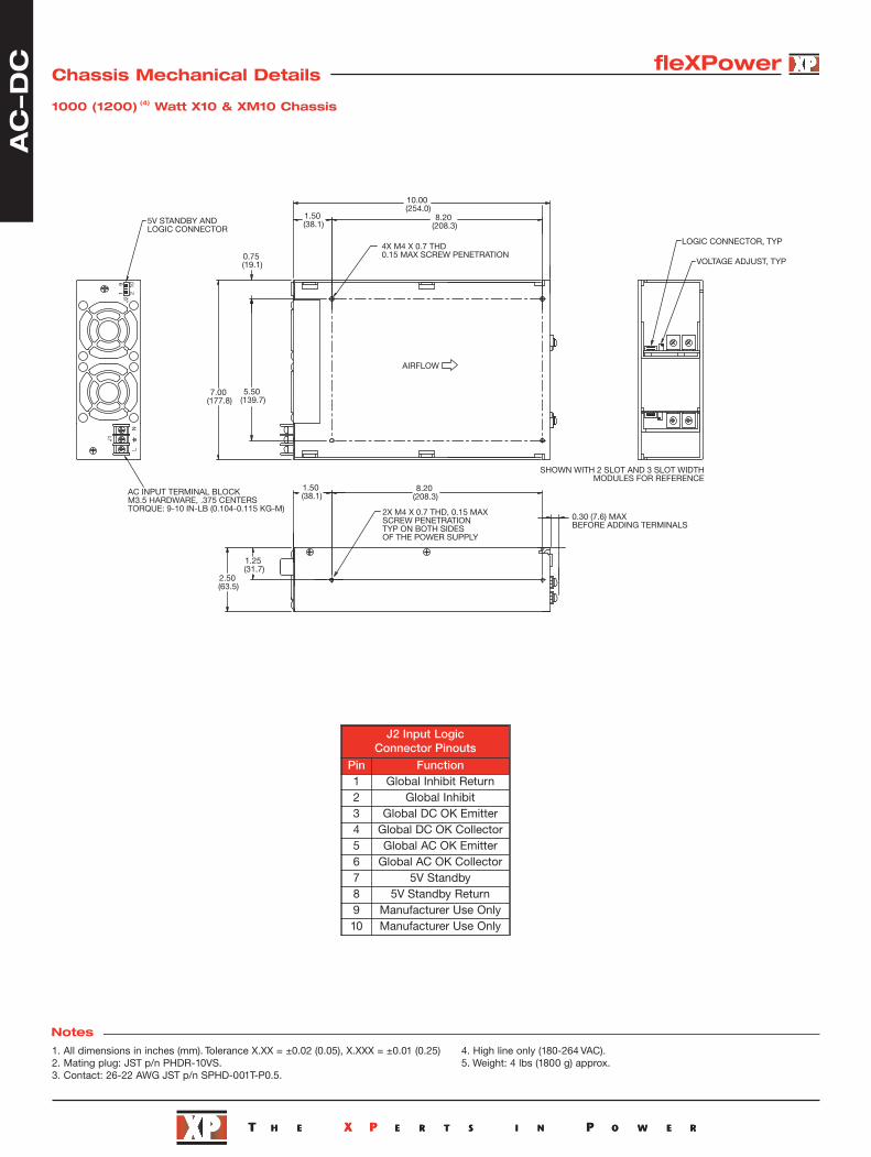
fleXPowerChassis Mechanical Details
1. All dimensions in inches (mm). Tolerance X.XX = ±0.02 (0.05), X.XXX = ±0.01 (0.25)
2. Mating plug: JST p/n PHDR-10VS.3. Contact: 26-22 AWG JST p/n SPHD-001T-P0.5.4. High line only (180-264 VAC).
5. Weights: 400 (600) W X4 & XM4 chassis: 2.75 lbs (1250 g) approx.500 (700) W X5 & XM5 chassis: 2.75 lbs (1250 g) approx.700 (900) W X7 & XM7 chassis: 2.75 lbs (1250 g) approx.900 (1100) W X9 & XM9 chassis: 3.3 lbs (1500 g) approx.
400 (600)(4) Watt X4 & XM4 Chassis, 500 (700)(4) Watt X5 & XM5 Chassis, 700 (900)(4) Watt X7 & XM7 Chassis
10.00 (254.0)
8.20 (208.3)1.50
(38.1)
0.75 (19.1)
4X M4 X 0.7 THD0.15 (3.8) MAX SCREW PENETRATION
2X M4 X 0.7 THD, 0.15 (3.8) MAXSCREW PENETRATION TYP ON BOTH SIDES OF THE POWER SUPPLY
1.25 (31.7)
0.30 (7.6) MAXBEFORE ADDING TERMINALS
109
21J2
J1
NL
AC INPUT TERMINAL BLOCKM3.5 HARDWARE, 0.375 (9.52) CENTERSTORQUE: 9-10 IN-LB(0.104-0.115 KG-M)
J2 INPUT LOGIC CONNECTOR
2.50 (63.5)
1.50 (38.1) 8.20 (208.3)
SHOWN WITH 2-SLOT-WIDTH MODULE FOR REFERENCE
5.00
(127.0)3.50(88.9)
AIRFLOW
J2 Input Logic Connector Pinouts
Pin Function1 Global Inhibit Return2 Global Inhibit3 Global DC OK Emitter4 Global DC OK Collector5 Global AC OK Emitter6 Global AC OK Collector7 5V Standby8 5V Standby Return9 Manufacturer Use Only10 Manufacturer Use Only
10.00 (254.0)
8.20 (208.3)1.50
(38.1)
4.50 (114.3)
0.75 (19.1)
4X M4 X 0.7 THD0.15 (3.8) MAX SCREW PENETRATION
LN
J1
J21 2
9 10
AC INPUT TERMINAL BLOCK M3.5 HARDWARE, 0.375 (9.52) CENTERSTORQUE: 9-10 IN-LB(0.104-0.115 KG-M)
J2 INPUTLOGIC CONNECTOR
SHOWN WITH 2-SLOT-WIDTHMODULE FOR REFERENCE
6.00(152.4)
2X M4 X 0.7 THD, 0.15 (3.8) MAX SCREW PENETRATION TYP ON BOTH SIDES OF THE POWER SUPPLY
1.25 (31.7)
0.30 (7.6) MAX BEFORE ADDING TERMINALS
2.50 (63.5)
8.20 (208.3)1.50 (38.1)
AIRFLOW
900 (1100)(4) Watt X9 & XM9 Chassis
AC
-D
C
Notes
fleXPower
1. All dimensions in inches (mm). Tolerance X.XX = ±0.02 (0.05), X.XXX = ±0.01 (0.25)2. Mating plug: JST p/n PHDR-10VS.3. Contact: 26-22 AWG JST p/n SPHD-001T-P0.5.
4. High line only (180-264 VAC).5. Weight: 4 lbs (1800 g) approx.
Chassis Mechanical Details
1000 (1200) (4) Watt X10 & XM10 Chassis
SHOWN WITH 2 SLOT AND 3 SLOT WIDTHMODULES FOR REFERENCE
L109
21J2
J1
N
7.00 (177.8)
10.00 (254.0)
8.20 (208.3)
1.50 (38.1)
5.50 (139.7)
0.75 (19.1) VOLTAGE ADJUST, TYP
LOGIC CONNECTOR, TYP4X M4 X 0.7 THD0.15 MAX SCREW PENETRATION
2X M4 X 0.7 THD, 0.15 MAXSCREW PENETRATIONTYP ON BOTH SIDESOF THE POWER SUPPLY
1.25 (31.7)
0.30 (7.6) MAXBEFORE ADDING TERMINALS
AC INPUT TERMINAL BLOCKM3.5 HARDWARE, .375 CENTERSTORQUE: 9-10 IN-LB (0.104-0.115 KG-M)
5V STANDBY AND LOGIC CONNECTOR
2.50 (63.5)
8.20 (208.3)
1.50 (38.1)
AIRFLOW
J2 Input Logic Connector Pinouts
Pin Function1 Global Inhibit Return2 Global Inhibit3 Global DC OK Emitter4 Global DC OK Collector5 Global AC OK Emitter6 Global AC OK Collector7 5V Standby8 5V Standby Return9 Manufacturer Use Only10 Manufacturer Use Only
AC
-D
C

Notes1. All dimensions in inches (mm). Tolerance X.XX = ±0.02 (0.05), X.XXX = ±0.01 (0.25)
2. Mating plug: JST p/n PHDR-10VS.3. Contact: 26-22 AWG JST p/n SPHD-001T-P0.5.4. High line only (180-264 VAC).
5. Weights: 800 (1200) W X4DD & XM4DD chassis: 5.5 lbs (2500 g) approx.1000 (1400) W X5DD & XM5DD chassis: 5.5 lbs (2500 g) approx.1400 (1800) W X7DD & XM7DD chassis: 5.5 lbs (2500 g) approx.1800 (2200) W X9DD & XM9DD chassis: 6.6 lbs (3000 g) approx.
109
21J2
J1
NL
109
21J2
J1
NL
AC INPUT TERMINAL BLOCKS(PARALLEL CONNECTED)M3.5 HARDWARE, 0.375 (9.52) CENTERSTORQUE: 9-10 IN-LB (0.104-0.115 KG-M)
5V STANDBY AND LOGIC CONNECTORS
EACH P/S IS SHOWN WITH 2-SLOT-WIDTH MODULE FOR REFERENCE
10.00 (254.0)
8.20 (208.3)1.50 (38.1)
3.50 (88.9)
.75 (19.1)
4X M4 X 0.7 THD0.15 (3.8) MAX SCREW PENETRATION
5.20 (132.1)
0.10 (2.5)TYP
0.228 (5.79)
0.228 (5.79)
1.25 (31.7)
0.30 (7.6) MAX BEFORE ADDING TERMINALS
1.50 (38.1)8.20 (208.3)
2.50 (63.5)
5.00 (127.0)
AIRFLOW
J2 Input Logic Connector Pinouts
Pin Function1 Global Inhibit Return2 Global Inhibit3 Global DC OK Emitter4 Global DC OK Collector5 Global AC OK Emitter6 Global AC OK Collector7 5V Standby8 5V Standby Return9 Inhibit Sum10 VCC Return
10.00 (254.0)
8.20 (208.3)1.50
(38.1)
4.50 (114.3)
0.75(19.1)
M4 X 0.7 THD0.15 (3.8) MAX SCREW PENETRATION
1.25 (31.7)
0.30 (7.6) MAXBEFORE ADDING TERMINALS
5.00(127.0)
8.20 (208.3)1.50 (38.1)
2.50 (63.5)
6.20 (157.5)
0.10 (2.5)TYP
LN
J1
J21 2
9 10
LN
J1
J21 2
9 10
AC INPUT TERMINAL BLOCKS(PARALLEL CONNECTED)
M3.5 HARDWARE, 0.375 (9.52) CENTERSTORQUE: 9-10 IN-LB (0.104-0.115 KG-M)
5V STANDBY AND LOGIC CONNECTORSEACH P/S IS SHOWN WITH 2-SLOT-WIDTH
MODULE FOR REFERENCE
AIRFLOW
0.228 (5.79)
0.228 (5.79)
800 (1200)(4) Watt X4DD & XM4DD Chassis, 1000 (1400)(4) Watt X5DD & XM5DD Chassis1400 (1800)(4) Watt X7DD & XM7DD Chassis
1800 (2200)(4) Watt X9DD & XM9DD Chassis
fleXPowerChassis Mechanical Details
AC
-D
C

Notes1. All dimensions in inches (mm). Tolerance X.XX = ±0.02 (0.05), X.XXX = ±0.01 (0.25)
2. Mating plug: JST p/n PHDR-10VS.3. Contact: 26-22 AWG JST p/n SPHD-001T-P0.5.
4. High line only (180-264 VAC).5. Weight: 8.0 lbs (3636 g) approx.
2000 (2400)(4) Watt X10DD & XM10DD Chassis
L109
21J2
J1
N
L109
21J2
J1
N
7.00 (177.8)
10.00 (254.0)
8.20 (208.3)
1.50 (38.1)
5.50 (139.7)
.75 (19.1) 4X M4 X 0.7 THD
0.15 MAX SCREW PENETRATION
4X M4 X 0.7 THD,TYP ON BOTH SIDESOF THE POWER SUPPLY
1.25 (31.7)
0.30 (7.6) MAXBEFORE
ADDING TERMINALSAC INPUT TERMINAL BLOCKS
(PARALLEL CONNECTION)M3.5 HARDWARE, .375 CENTERS
TORQUE: 9-10 IN-LB (0.104-0.115 KG-M)
5V STANDBY AND LOGIC CONNECTOR
2.50 (63.5)
5.00 (127.0)
1.50 (38.1)
8.20 (208.3)
LOGIC CONNECTOR, TYP
VOLTAGE ADJUST, TYP
0.228(5.79)
0.228(5.79)
AIRFLOW
J2 Input Logic Connector Pinouts
Pin Function1 Global Inhibit Return2 Global Inhibit3 Global DC OK Emitter4 Global DC OK Collector5 Global AC OK Emitter6 Global AC OK Collector7 5V Standby8 5V Standby Return9 Inhibit Sum10 VCC Return
AC
-D
C fleXPowerChassis Mechanical Details

05 Jan 16
Notes1. All dimensions in inches (mm). Tolerance X.XX = ±0.02 (0.05), X.XXX = ±0.01 (0.25)
2. Mating plug: JST p/n PHDR-10VS.3. Contact: 26-22 AWG JST p/n SPHD-001T-P0.5.
4. High line only (180-264 VAC).5. Weight: 8.0 lbs (3636 g) approx.
1500 (2500)(4) Watt X15 & XM15 Chassis
11.00 (279.4)
Fan Control Card
M4 x 0.7 THDOutput Hardware, Typ
Voltage Adjust, Typ
Logic Connector, Typ
P/S is shown with 2-slot-width modules and fan control card for reference
1.75 (44.5)
5.00 (127.0)
5.00(127.0)
91
102
J2
N
J1
L
5 V standby & logic connector(see pin table)
AC Input Terminal Block6-32 Hardware, 0.375 centers
2 x 1.75(44.5)
2 x 0.75 (19.1)
2 x 8.950 (227.33)
0.75(19.1)
3.500(88.9)
4 x M4 x 0.7 THD 0.15 (3.8) Max Screw PenetrationBoth sides of P/S
2 x 3.500(88.9)
4 x M4 x 0.7 THD0.15 (3.8) Max Screw Penetration
8.950 (227.33)
AIRFLOW
J2 Input Logic Connector Pinouts
Pin Function1 Global Inhibit Return2 Global Inhibit3 Global DC OK Emitter4 Global DC OK Collector5 Global AC OK Emitter6 Global AC OK Collector7 5V Standby8 5V Standby Return9 Inhibit Sum (Internal Use Only)10 VCC Return (Internal Use Only)
AC
-D
C
fleXPowerChassis Mechanical Details