Embed Size (px)
Citation preview
400410
R880
®
Price Index
Special Features / Options
Assembly Tips
Usage Guidelines
• When quiet operation is required• When very high speeds and/or
accelerations are required• For long travels• For high fill weights
• When side-mounting with a longunsupported length is required‰ Series 4040/4041/R8840
• When a simpler, low-cost solution isrequired‰ Series 14040/R18840
• If an extreme vibration-free solutionis required‰ Series 14040/R18840
Opening Energy Chains®: Remove cross-bars and clips - Insert screwdriver into theslot, push down, release by lever action
Series 400
Series R880
Series 410
Remove lids/bottoms (Energy Tubes) -Insert screw driver into the slot, release bylever action
Energy Chain System® E4/100Series 400/410/R880
6.159
Order Example: Complete Energy Chain®
Please indicate chain length or number of links. Example:
9.84 ft (3 m) 400-30-300-0 Energy Chain®
With 2 separators 411 assembled every 2nd link Interior separation
1 Set 40000-30-12P Mounting bracket
2.20” 2.20”
Also available asE4/00-NC without camber:400-NCST
Clean-Room Cleanroom test upon request
Low noise version E4/101Series 401 available withspecial rubber pads
ESD classification:Electrically conductiveESD/ATEX version upon request
Features & BenefitsKMA mounting brackets with attachment points
on all sides
Crossbars on Energy Chains® are removable
along both radii
Stop dog with brake for noise reduction
Hinged snap-open removable lids along the
outer radius
Optimized glide pads with lateral wear
allowance
Integrated strain relief possible
Locking or pivoting mounting brackets available
Dirt-repellent exterior
Closed and open styles can be combined
Wide, rounded crossbars
Numerous interior separation possibilities
Energy Chains® also available with reverse
bending radius “RBR”
Other Installation Methods
Vertical, hanging ≤ 328 ft (100 m)
Vertical, standing ≤ 19.69 ft (6 m)
Side-mounted, unsupp. ≤ 8.20 ft (2.5 m)
Rotary requires further calculation
energy chain® configurator
Long Travels -Gliding
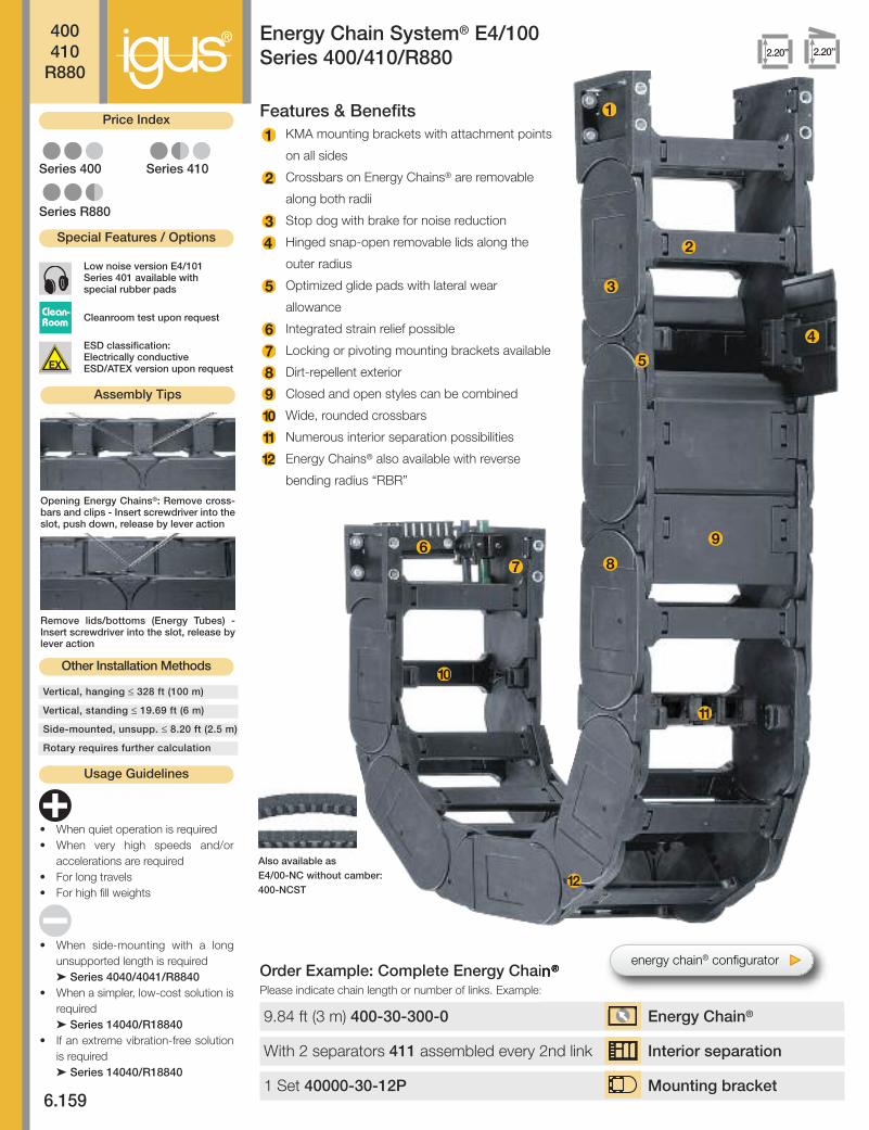
®Energy Chain System® E4/100Series 400/410/R880Installation Dimensions
400410
R880
Legend
2.20”
PD
F:
ww
w.ig
us.
com
/e-c
hai
n-p
dfs
Sp
ecs/
CA
D/R
FQ
: w
ww
.igu
s.co
m/e
-ch
ain
sR
oH
S in
fo:
ww
w.ig
us.
com
/Ro
HS
6.160
If the unsupported length isexceeded, the EnergyChain®/Tube must glide onitself. This requires a guidetrough.Design, Chapter 1
Details of materialproperties
‰ Design , Chapter 1
S = Length of travel
R = Bending radius
H = Nominal clearance
height
HF = Required clearance
height
HRI = Trough inner height
D = Overlength Energy
Chain® radius in final
position
K = π • R + safety buffer
D2 = Overlength - long
travels, gliding
K2 = *Add-on
H2 = *Mounting height
*If the mounting bracketlocation is set lower
F °
Short travel, unsupported length● FLB = unsupported with permitted sag
● FLG = unsupported with straight upper run
Further information ‰ Design, Chapter 1
.34
1.01
0
.67
0 3.28 6.56 9.84 13.12 16.41
6.72
13.44
26.88
33.60
20.16
1.34
4.03
FLG
FLB
Fill
wei
ght l
bs/f
t
Unsupported length in ft FLB / FLG
Length of travel S in ft0 6.56 13.12 19.69 26.25 32.81
For long travels with lowered mounting heightLong travel lengths from 32.8 ft.(10m) to max. 1,312.4 ft. (400m)
FLG
FLB
H
HF
S (FLG)
S (FLB)
D
H
H -
3.3
1 (8
4)
R
S/2
S3.
31 (84)
3.58(91)
HF=
H +
1.9
6 (5
0)Moving End
Fixed End
SD2S/2 S/2
R
K2
HR
I
H2
Guide trough with glide bar Guide trough without glide bar
Total length of guide trough
Fixed endMoving end
The required clearance height: HF = H + 1.96 in. (50 mm) (with 2.02 lbs/ft (3 kg/m) fill weight. Please consult igus® if spaceis particularly restricted.
Pitch per link: = 3.58” (91 mm)
Links per ft (m): = 3.35 (11)
For center mount applications:
Chain length = s/2 +K
Speed / acceleration FLG max. 65.6 ft/s (20 m/s) / max. 656 ft/s2 (200 m/s2)
Speed / acceleration FLB max. 9.84 ft/s (3 m/s) / max. 19.69 ft/s2 (6 m/s2)
Gliding speed / acceleration (maximum) max. 32.8 ft/s (10 m/s) / max. 164 ft/s2 (50 m/s2)
Material - permitted temperature igumid G / -40°F (-40°C) up to +248°F (+120° C)
Flammability Class, igumid G VDE 0304 IIC UL94 HB
R 5.31 (135) 5.91 (150) 6.89 (175) 7.87 (200) 9.45 (240) 9.84 (250) 11.81 (300) 13.78 (350) 15.75 (400) 19.68 (500)
H*-0
+25 14.17 (360) 15.16 (385) 17.13 (435) 19.09 (485) 22.24 (565) 23.03 (585) 26.97 (685) 30.91 (785) 34.84 (885) 42.72 (1085)
D 10.63 (270) 11.22 (285) 12.20 (310) 13.19 (335) 14.76 (375) 15.16 (385) 17.13 (435) 19.09 (485) 21.06 (535) 25.00 (635)
K 25.59 (650) 29.53 (750) 32.48 (825) 35.43 (900) 40.16 (1020) 41.34 (1050) 48.23 (1225) 52.76 (1340) 57.09 (1450) 69.88 (1775)
R 5.31 (135) 5.91 (150) 6.89 (175) 7.87 (200) 9.45 (240) 9.84 (250) 11.81 (300) 13.78 (350) 15.75 (400) 19.68 (500)
H2 - 10.47 (266) 10.47 (266) 10.47 (266) 10.47 (266) 10.47 (266) 10.47 (266) 10.47 (266) 10.47 (266) 10.47 (266)
D2 - 18.90 (480) 23.62 (600) 28.74 (730) 36.22 (920) 37.40 (950) 46.46 (1180) 56.69 (1440) 60.24 (1530) 74.80 (1900)
K2 - 32.24 (819) 42.99 (1092) 50.16 (1274) 60.91 (1547) 60.91 (1547) 78.82 (2002) 89.57 (2275) 100.31(2548) 128.98 (3276)
Technical Data
For support of the lower run, see Chapter 9 for the Support Tray tool kit
For center mount applications:
Chain length: = s/2 +K2
UnsupportedEnergy Chains®
feature positivecamber over short travels.This must be accounted forwhen specifying the clear-ance height. Please refer toInstallation dimensions forfurther details.
Short Travels -Unsupported
energy chain® configurator

Part Number Structure
Color - Black
Bending radius
Width
Series
Part Number Structure
Color - Black
Bending radius
Width
Series
®400410
R880
6.161
Inte
rnet
: h
ttp
://w
ww
.igu
s.co
mem
ail:
sale
s@ig
us.
com
Qu
ickS
pec
: h
ttp
://w
ww
.igu
s.co
m/q
uic
ksp
ec
Tele
ph
on
e1-
800-
521-
2747
Fax
1-
401-
438-
7270
igu
s®E
ner
gy
Ch
ain
Sys
tem
®
Energy Chain System® E4/100Series 400/410/R880
Part Number Structure
Color - Black
Bending radius
Width
Series
BaBi
1.97max.
2.20
(56)
3.31
(84)
Series400
BaBi
1.97max.
2.20
(56)
3.31
(84)
Series410
BaBi
1.97max.
2.20
(56)
3.31
(84)
SeriesR880
RRR
RRR
RRR
410- 13- 0250-
Series 400 - Energy Chain® with crossbars every link
• Crossbars every link• For use with rigid hydraulic
hoses• For particularly demanding
applications• Can be opened from both
sides
Series 410 - Energy Chain® with crossbars every other link
• Crossbars every other link• Standard configuration• For nearly every situation• Can be opened from both
sides• Easy assembly• Stable• Cost-effective
Series R880 - fully enclosed Energy Tube
Energy Chain® as separate parts, links and side plates
• Fully enclosed• Excellent cable and hose
protection against dirt• Protection against hot chips
up to 1,562°F (850°C)• Lids along inner radius are
completely removable• Lids along the outer radius
are single-sided, snap open,hinged on one side as well ascompletely removable
400- 13- 0250-
D
H
H -
3.3
1 (8
4)
R
S/2
S
3.31 (84)
3.58(91)
HF=
H +
1.9
6 (5
0)
Moving End
Fixed End
880- 25- 0250-
Single crossbar, Energy Chain® - Part No. 450- BiSingle lid, Energy Tube - Part No. 885- Bi
Single bottom, Energy Tube - Part No. 886- Bi
Outer side link, single part - Part No. 400-01(Suitable for all radii)
Bi
Bi
Bi
Inner side link, single part - Part No. 400-02- BiR
Inner side link
Inner side links, each left/right
or outer side links, each left/right
Outer side link
energy chain® configurator
® 400410
R880
6.162
PD
F:
ww
w.ig
us.
com
/e-c
hai
n-p
dfs
Sp
ecs/
CA
D/R
FQ
: w
ww
.igu
s.co
m/e
-ch
ain
sR
oH
S in
fo:
ww
w.ig
us.
com
/Ro
HS
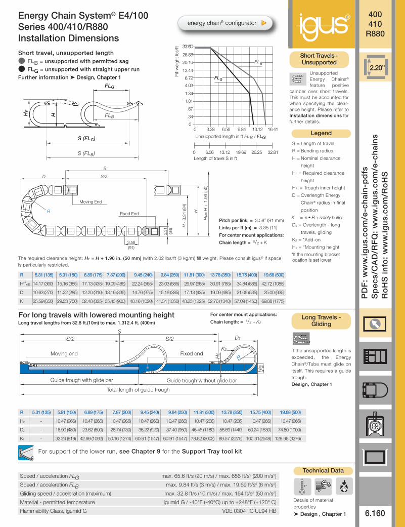
Energy Chain System® E4/100Series 400/410/R880
Part Number.Crossbars Crossbars Tube Bi Ba 400 410 R880Every link Every other Version in. (mm) in. (mm) lbs/ft (kg/m) lbs/ft (kg/m) lbs/ft (kg/m)
400-05- 410-05- -0 1.97 (50) 3.31 (84) ≈ 2.31 (3.44) ≈ 2.10 (3.12) –
400-06- 410-06- -0 2.56 (65) 3.90 (99) ≈ 2.35 (3.50) ≈ 2.15 (3.20) –
400-07- 410-07- 880-07- -0* 2.95 (75) 4.29 (109) ≈ 2.37 (3.53) ≈ 2.31 (3.44) ≈ 2.67 (3.98)
400-10- 410-10- 880-10- -0 3.94 (100) 5.28 (134) ≈ 2.49 (3.71) ≈ 2.37 (3.53) ≈ 2.87 (4.27)
400-11- 410-11 - -0 4.41 (112) 5.79 (147) ≈ 2.58 (3.84) ≈ 2.42 (3.60) –
400-12- 410-12- 880-12- -0 4.92 (125) 6.26 (159) ≈ 2.63 (3.91) ≈ 2.44 (3.63) ≈ 3.11 (4.63)
400-13- 410-13- -0 5.39 (137) 6.77 (172) ≈ 2.72 (4.04) ≈ 2.49 (3.70) –
400-15- 410-15- 880-15- -0 5.91 (150) 7.24 (184) ≈ 2.76 (4.10) ≈ 2.51 (3.73) ≈ 3.40 (5.06)
400-16- 410-16- -0 6.38 (162) 7.76 (197) ≈ 2.83 (4.21) ≈ 2.54 (3.78) –
400-17- 410-17- -0 6.89 (175) 8.23 (209) ≈ 2.90 (4.32) ≈ 2.58 (3.84) –
400-18- 410-18- -0 7.36 (187) 8.74 (222) ≈ 2.98 (4.43) ≈ 2.61 (3.89) –
400-20- 410-20- 880-20- -0 7.87 (200) 9.21 (234) ≈ 3.00 (4.46) ≈ 2.63 (3.91) ≈ 3.78 (5.63)
400-21- 410-21- -0 8.35 (212) 9.72 (247) ≈ 3.07 (4.57) ≈ 2.66 (3.96) –
400-22- 410-22- -0 8.86 (225) 10.20 (259) ≈ 3.11 (4.63) ≈ 2.68 (3.99) –
400-23- 410-23- -0 9.33 (237) 10.71 (272) ≈ 3.20 (4.76) ≈ 2.73 (4.06) –
400-25- 410-25- 880-25- -0 9.84 (250) 11.18 (284) ≈ 3.26 (4.85) ≈ 2.76 (4.10) ≈ 4.27 (6.36)
400-26- 410-26- -0 10.31 (262) 11.69 (297) ≈ 3.32 (4.94) ≈ 2.79 (4.15) –
400-27- 410-27- 880-27- -0 10.83 (275) 12.17 (309) ≈ 3.39 (5.05) ≈ 2.82 (4.20) ≈ 4.52 (6.72)
400-28- 410-28- -0 11.30 (287) 12.68 (322) ≈ 3.41 (5.07) ≈ 2.83 (4.21) –
400-30- 410-30- 880-30- -0 11.81 (300) 13.15 (334) ≈ 3.56 (5.29) ≈ 2.90 (4.32) ≈ 4.72 (7.02)
400-31- 410-31- -0 12.28 (312) 13.66 (347) ≈ 3.56 (5.29) ≈ 2.90 (4.32) –
400-32- 410-32- -0 12.79 (325) 14.13 (359) ≈ 3.62 (5.38) ≈ 2.94 (4.37) –
400-33- 410-33- -0 13.27 (337) 14.65 (372) ≈ 3.74 (5.56) ≈ 3.00 (4.46) –
400-35- 410-35- 880-35- -0 13.78 (350) 15.12 (384) ≈ 3.84 (5.71) ≈ 3.04 (4.53) ≈ 5.19 (7.72)
400-36- 410-36- -0 14.25 (362) 15.63 (397) ≈ 3.84 (5.71) ≈ 3.04 (4.53) –
400-37- 410-37- -0 14.76 (375) 16.10 (409) ≈ 3.85 (5.73) ≈ 3.05 (4.54) –
400-38- 410-38- -0 15.24 (387) 16.61 (422) ≈ 3.91 (5.82) ≈ 3.08 (4.59) –
400-40- 410-40- 880-40- -0 15.75 (400) 17.09 (434) ≈ 4.05 (6.02) ≈ 3.15 (4.69) ≈ 5.86 (8.72)
400-41- 410-41- -0 16.22 (412) 17.60 (447) ≈ 4.15 (6.17) ≈ 3.20 (4.76) –
400-42- 410-42- -0 16.73 (425) 18.07 (459) ≈ 4.25 (6.33) ≈ 3.25 (4.84) –
400-43- 410-43- -0 17.20 (437) 18.58 (472) ≈ 4.29 (6.39) ≈ 3.27 (4.87) –
400-45- 410-45- -0 17.72 (450) 19.06 (484) ≈ 4.34 (6.46) ≈ 3.30 (4.91) –
400-46- 410-46- 880-46- -0 18.19 (462) 19.57 (497) ≈ 4.35 (6.48) ≈ 3.31 (4.92) ≈ 6.18 (9.19)
400-47- 410-47- -0 18.70 (475) 20.04 (509) ≈ 4.44 (6.61) ≈ 3.35 (4.98) –
400-48- 410-48- -0 19.17 (487) 20.55 (522) ≈ 4.47 (6.65) ≈ 3.37 (5.01) –
400-50- 410-50- -0 19.69 (500) 21.02 (534) ≈ 4.53 (6.74) ≈ 3.39 (5.05) –
400-51- 410-51- -0 20.16 (512) 21.54 (547) ≈ 4.55 (6.77) ≈ 3.40 (5.06) –
400-52- 410-52- -0 20.67 (525) 22.01 (559) ≈ 4.58 (6.81) ≈ 3.41 (5.08) –
400-53- 410-53- -0 21.14 (537) 22.52 (572) ≈ 4.68 (6.96) ≈ 3.47 (5.16) –
400-55- 410-55- -0 21.65 (550) 22.99 (584) ≈ 5.01 (7.45) ≈ 3.63 (5.40) –
400-60- 410-60- -0 23.62 (600) 24.96 (634) ≈ 5.14 (7.65) ≈ 3.70 (5.50) –
Choose from the radii below for all of the above sizes
Radius (mm) Example: 400-30- -0
Supplement part number with required radius. Example: 400-30- -0Pitch: 3.58 in. (91mm) per link links/ft(m) = 3.35 (11)
300
300
R 5.31 (135) 5.91 (150) 6.89 (175) 7.87 (200) 9.45 (240) 9.84 (250) 11.81 (300) 13.78 (350) 15.75 (400) 19.69 (500)
H*-0
+25 14.17 (360) 15.16 (385) 17.13 (435) 19.09 (485) 22.24 (565) 23.03 (585) 26.97 (685) 30.91 (785) 34.84 (885) 42.72 (1085)
D 10.63 (270) 11.22 (285) 12.20 (310) 13.19 (335) 14.76 (375) 15.16 (385) 17.13 (435) 19.09 (485) 21.06 (535) 25.00 (635)
K 25.59 (650) 29.53 (750) 32.48 (825) 35.43 (900) 40.16 (1020) 41.34 (1050) 48.23 (1225) 52.76 (1340) 57.09 (1450) 69.88 (1775)
500400 350 300 250 240 200 175150 135**
** This radius is not available for the R880 Series *Removable lid only, no hinged option
0=Standard color black. For other colors see Chapter 1For wider chains see page 6.95. For large diameter hoses see page 6.95
energy chain® configurator
Vertical
separator
401
®400410
R880
6.163
Inte
rnet
: h
ttp
://w
ww
.igu
s.co
mem
ail:
sale
s@ig
us.
com
Qu
ickS
pec
: h
ttp
://w
ww
.igu
s.co
m/q
uic
ksp
ec
Tele
ph
on
e1-
800-
521-
2747
Fax
1-
401-
438-
7270
igu
s®E
ner
gy
Ch
ain
Sys
tem
®
Energy Chain System® E4/100Series 400/410/R880Interior Separation
Locking
separator
404
Locking
separator
406
Vertical
separator
483
415-X411A 414 411484
484411 min. 1.30”33 mm
min. 0.63”16 mm
EnergyChain®
EnergyTube
Vertical separator
Unassembled Part No. 401
Assembled Part No. 411
.12 (3)
.71(18)
Vertical separator
Unassembled Part No. 483
Assembled Part No. 484
.12 (3)
.31(8)
STANDARD
Locking separator(chain only)
Unassembled Part No. 404
Assembled Part No. 414
Locking separator(tube only)
Unassembled Part No. 406
Assembled Part No. 416
.12 (3)
.83(21)
.14 (3.5)
.71(18)
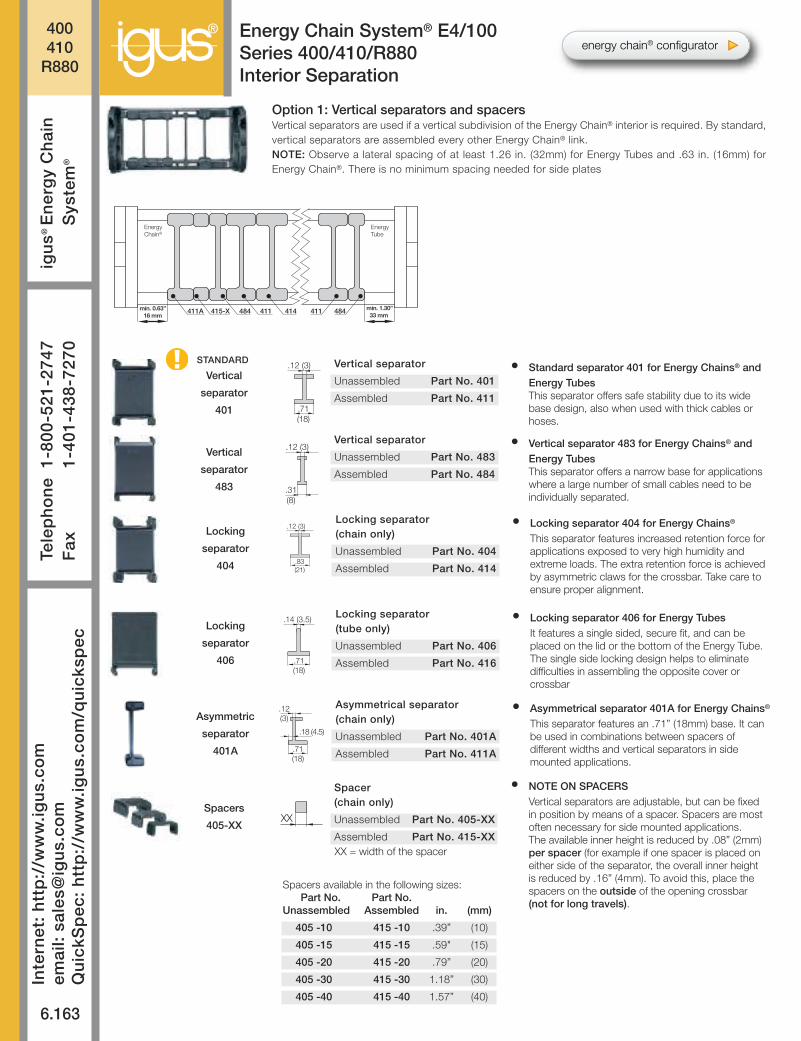
• Standard separator 401 for Energy Chains® andEnergy TubesThis separator offers safe stability due to its widebase design, also when used with thick cables orhoses.
• Vertical separator 483 for Energy Chains® andEnergy TubesThis separator offers a narrow base for applicationswhere a large number of small cables need to beindividually separated.
XX = width of the spacer
• Locking separator 404 for Energy Chains®
This separator features increased retention force forapplications exposed to very high humidity andextreme loads. The extra retention force is achievedby asymmetric claws for the crossbar. Take care toensure proper alignment.
• Locking separator 406 for Energy TubesIt features a single sided, secure fit, and can beplaced on the lid or the bottom of the Energy Tube.The single side locking design helps to eliminatedifficulties in assembling the opposite cover orcrossbar
Asymmetric
separator
401A
Asymmetrical separator(chain only)
Unassembled Part No. 401A
Assembled Part No. 411A
.12(3)
.71(18)
.18 (4.5)
• Asymmetrical separator 401A for Energy Chains®
This separator features an .71” (18mm) base. It canbe used in combinations between spacers ofdifferent widths and vertical separators in sidemounted applications.
Spacers
405-XXXX
Spacer(chain only)
Unassembled Part No. 405-XX
Assembled Part No. 415-XX
• NOTE ON SPACERSVertical separators are adjustable, but can be fixedin position by means of a spacer. Spacers are mostoften necessary for side mounted applications.The available inner height is reduced by .08” (2mm)per spacer (for example if one spacer is placed oneither side of the separator, the overall inner heightis reduced by .16” (4mm). To avoid this, place thespacers on the outside of the opening crossbar(not for long travels).
Option 1: Vertical separators and spacersVertical separators are used if a vertical subdivision of the Energy Chain® interior is required. By standard,vertical separators are assembled every other Energy Chain® link.NOTE: Observe a lateral spacing of at least 1.26 in. (32mm) for Energy Tubes and .63 in. (16mm) forEnergy Chain®. There is no minimum spacing needed for side plates
Spacers available in the following sizes:Part No. Part No.
Unassembled Assembled in. (mm)
405 -10 415 -10 .39” (10)
405 -15 415 -15 .59" (15)
405 -20 415 -20 .79” (20)
405 -30 415 -30 1.18” (30)
405 -40 415 -40 1.57” (40)
energy chain® configurator
® 400410
R880
6.164
PD
F:
ww
w.ig
us.
com
/e-c
hai
n-p
dfs
Sp
ecs/
CA
D/R
FQ
: w
ww
.igu
s.co
m/e
-ch
ain
sR
oH
S in
fo:
ww
w.ig
us.
com
/Ro
HS
Energy Chain System® E4/100Series 400/410/R880Interior Separation
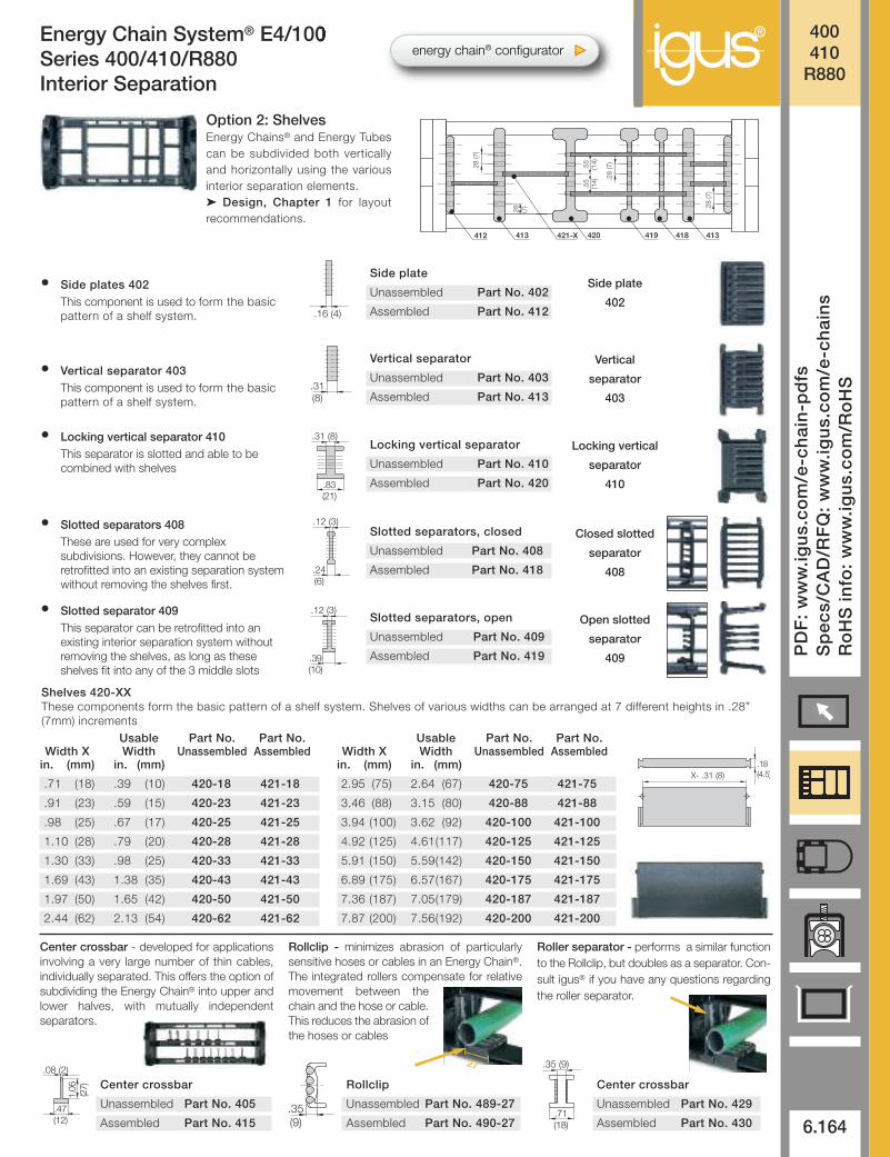
Center crossbar - developed for applicationsinvolving a very large number of thin cables,individually separated. This offers the option ofsubdividing the Energy Chain® into upper andlower halves, with mutually independentseparators.
Rollclip - minimizes abrasion of particularlysensitive hoses or cables in an Energy Chain®.The integrated rollers compensate for relativemovement between thechain and the hose or cable.This reduces the abrasion ofthe hoses or cables
Roller separator - performs a similar functionto the Rollclip, but doubles as a separator. Con-sult igus® if you have any questions regardingthe roller separator.
412 421-X 418413
.28
(7)
419420
.28
(7)
413
.55
(14)
.28
(7)
.28
(7)
.55
(14)
Option 2: ShelvesEnergy Chains® and Energy Tubescan be subdivided both verticallyand horizontally using the variousinterior separation elements.‰ Design, Chapter 1 for layoutrecommendations.
Side plate
402
Vertical
separator
403
Locking vertical
separator
410
Closed slotted
separator
408
Open slotted
separator
409
Side plate
Unassembled Part No. 402
Assembled Part No. 412
Center crossbar
Unassembled Part No. 405
Assembled Part No. 415
Shelves 420-XXThese components form the basic pattern of a shelf system. Shelves of various widths can be arranged at 7 different heights in .28”(7mm) increments
• Locking vertical separator 410This separator is slotted and able to becombined with shelves
• Slotted separators 408These are used for very complexsubdivisions. However, they cannot beretrofitted into an existing separation systemwithout removing the shelves first.
• Slotted separator 409This separator can be retrofitted into anexisting interior separation system withoutremoving the shelves, as long as theseshelves fit into any of the 3 middle slots
.16 (4)
Vertical separator
Unassembled Part No. 403
Assembled Part No. 413.31(8)
Locking vertical separator
Unassembled Part No. 410
Assembled Part No. 420
.31 (8)
.83(21)
.12 (3)
.24(6)
Slotted separators, closed
Unassembled Part No. 408
Assembled Part No. 418
.12 (3)
.39(10)
Slotted separators, open
Unassembled Part No. 409
Assembled Part No. 419
.18 (4.5)X- .31 (8)
Usable Part No. Part No.Width X Width Unassembled Assembled
in. (mm) in. (mm)
.71 (18) .39 (10) 420-18 421-18
.91 (23) .59 (15) 420-23 421-23
.98 (25) .67 (17) 420-25 421-25
1.10 (28) .79 (20) 420-28 421-28
1.30 (33) .98 (25) 420-33 421-33
1.69 (43) 1.38 (35) 420-43 421-43
1.97 (50) 1.65 (42) 420-50 421-50
2.44 (62) 2.13 (54) 420-62 421-62
Usable Part No. Part No.Width X Width Unassembled Assembled
in. (mm) in. (mm)
2.95 (75) 2.64 (67) 420-75 421-75
3.46 (88) 3.15 (80) 420-88 421-88
3.94 (100) 3.62 (92) 420-100 421-100
4.92 (125) 4.61(117) 420-125 421-125
5.91 (150) 5.59(142) 420-150 421-150
6.89 (175) 6.57(167) 420-175 421-175
7.36 (187) 7.05(179) 420-187 421-187
7.87 (200) 7.56(192) 420-200 421-200
• Side plates 402This component is used to form the basicpattern of a shelf system.
• Vertical separator 403This component is used to form the basicpattern of a shelf system.
.08 (2)
.47(12)
1.06 (27) Rollclip
Unassembled Part No. 489-27
Assembled Part No. 490-27.35(9)
Center crossbar
Unassembled Part No. 429
Assembled Part No. 430
.35 (9)
.71(18)
27
energy chain® configurator
®400410
R880
6.165
Inte
rnet
: h
ttp
://w
ww
.igu
s.co
mem
ail:
sale
s@ig
us.
com
Qu
ickS
pec
: h
ttp
://w
ww
.igu
s.co
m/q
uic
ksp
ec
Tele
ph
on
e1-
800-
521-
2747
Fax
1-
401-
438-
7270
igu
s®E
ner
gy
Ch
ain
Sys
tem
®
Energy Chain System® E4/100Series 400/410/R880Special Accessories
+.04
(1
)
.79
(20 )
Bi 1 Bi 2 Bi 3
Bi 3 + .75 (19)
ø.35 (9)
3.13
(79.5).88
(22.5)
Bi 1 + .75 (19)
[Bi 1 + .75 (19) + Bi 2 + .63 (16) + Bi 3 + .75 (19)] + .71 (18) ± .12 (3)
Bi 2 + .63 (16)
Bi 1 + .75 (19) + Bi 2 + .63 (16) + Bi 3 + .75 (19) ± .12 (3)
1.38
(35)
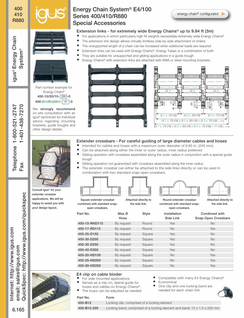
Extension links - for extremely wide Energy Chains® up to 9.84 ft (3m)• For applications in which particularly high fill weights necessitate extremely wide Energy Chains®
• The extension link design allows virtually limitless side-by-side attachment of chains
• The unsupported length of a chain can be increased when additional loads are required
• Extension links can be used with Energy Chains®, Energy Tubes or a combination of both
• They are suitable for unsupported and gliding applications in a guide trough• Energy Chains® with extension links are attached with KMA or steel mounting brackets.
Extender crossbars - For careful guiding of large diameter cables and hoses• Intended for cables and hoses with a maximum outer diameter of 9.65 in. (245 mm).• Can be attached along either the inner or outer radius, inner radius preferred• Gliding operation with crossbars assembled along the outer radius in conjunction with a special guide
trough• Gliding operation not guaranteed with crossbars assembled along the inner radius• The extender crossbar can either be attached to the side links directly or can be used in
combination with two standard snap-open crossbars.
E4 clip on cable binder• For side mounted applications• Serves as a clip-on, lateral guide for
hoses and cables on Energy Chains®
• The loops can be adjusted as needed
• Compatible with many E4 Energy Chains®
• Economical• One clip and one locking band are
needed for each chain link
Part No. Max Ø Style Installation Combined withHose Side Link Snap-Open Crossbars
450-15-RHD115 By request Round Yes No
450-17-RD115 By request Round No Yes
450-25-D150 By request Square Yes No
450-30-D200 By request Square Yes No
450-35-D250 By request Square Yes No
450-40-D300 By request Square Yes No
450-20-HD150 By request Square No Yes
450-25-HD200 By request Square No Yes
450-30-HD250 By request Square No Yes
Part No. Form
450-B12 Locking clip, comprised of a locking element
450-B12-200 Locking band, comprised of a locking element and band; 12 x 1.5 x 200 mm
Consult igus® for your
extender crossbar
applications. We will be
happy to assist you with
your design layout.
Square extender crossbarcombined with standard snap-
open crossbars.
Attached directly tothe side link.
Round extender crossbarcombined with standard snap-
open crossbars.
Attached directly tothe side link.
We strongly recommendon-site consultation with anigus® technician for individualadvice regarding mountingbrackets, guide troughs andother design details.
Part number example forEnergy Chain®
400-10/20/10- 200-0
400-Bi1/Bi2/Bi3- -0
200
R
energy chain® configurator
® 400410
R880
6.166
PD
F:
ww
w.ig
us.
com
/e-c
hai
n-p
dfs
Sp
ecs/
CA
D/R
FQ
: w
ww
.igu
s.co
m/e
-ch
ain
sR
oH
S in
fo:
ww
w.ig
us.
com
/Ro
HS
Energy Chain System® E4/100Series 400/410/R880Mounting Brackets, KMA
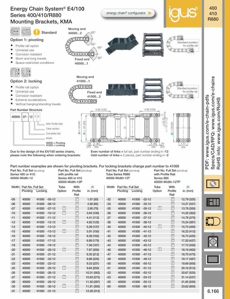
Option 1: pivoting
• Profile rail option• Universal use• Corrosion resistant• Short and long travels• Space-restricted conditions
Standard
45°
45°
45°
45°
Moving end40000...2
Fixed end40000...1
Bi
1.77(45)
ø.35
(9)
t =
.41
(11.
2)
4.92 (125)
1.38(35)
.79(20)
Bi +
1.6
1 (4
1)
Bi +
.91
(23)
4.92 (125)
.79(20)
1.38(35)
Bi +
1.6
1 (4
1)
Standard positionfor profile rail
Standard positionfor profile rail
Option 2: locking
• Profile rail option• Universal use• Corrosion resistant• Extreme accelerations• Vertical hanging/standing travels
Moving end41000...1
Fixed end41000...2
-05 40000 41000 -05-12 1.97 (50)
-06 40000 41000 -06-12 2.56 (65)
-07 40000 41000 -07-12 2.95 (75)
-10 40000 41000 -10-12 3.94 (100)
-11 40000 41000 -11-12 4.41 (112)
-12 40000 41000 -12-12 4.92 (125)
-13 40000 41000 -13-12 5.39 (137)
-15 40000 41000 -15-12 5.91 (150)
-16 40000 41000 -16-12 6.38 (162)
-17 40000 41000 -17-12 6.89 (175)
-18 40000 41000 -18-12 7.36 (187)
-20 40000 41000 -20-12 7.87 (200)
-21 40000 41000 -21-12 8.35 (212)
-22 40000 41000 -22-12 8.86 (225)
-23 40000 41000 -23-12 9.33 (237)
-25 40000 41000 -25-12 9.84 (250)
-26 40000 41000 -26-12 10.31 (262)
-27 40000 41000 -27-12 10.83 (275)
-28 40000 41000 -28-12 11.30 (287)
-30 40000 41000 -30-12 11.81 (300)
-31 40000 41000 -31-12 12.28 (312)
-32 40000 41000 -32-12 12.79 (325)
-33 40000 41000 -33-12 13.27 (337)
-35 40000 41000 -35-12 13.78 (350)
-36 40000 41000 -36-12 14.25 (362)
-37 40000 41000 -37-12 14.76 (375)
-38 40000 41000 -38-12 15.24 (387)
-40 40000 41000 -40-12 15.75 (400)
-41 40000 41000 -41-12 16.22 (412)
-42 40000 41000 -42-12 16.73 (425)
-43 40000 41000 -43-12 17.20 (437)
-45 40000 41000 -45-12 17.72 (450)
-46 40000 41000 -46-12 18.19 (462)
-47 40000 41000 -47-12 18.70 (475)
-48 40000 41000 -48-12 19.17 (487)
-50 40000 41000 -50-12 19.69 (500)
-51 40000 41000 -51-12 20.16 (512)
-52 40000 41000 -52-12 20.67 (525)
-53 40000 41000 -53-12 21.14 (537)
-55 40000 41000 -55-12 21.65 (550)
-60 40000 41000 -60-12 23.62 (600)
PP
P
P
P
P
P
P
P
P
P
P
P
P
P
P
P
P
P
P
P
P
P
P
P
P
P
P
P
P
P
P
P
P
P
P
P
P
P
P
P
T
T
T
T
T
T
T
T
T
T
T
Width Part No. Full Set Tube With BiPivoting Locking Option Profile in. (mm)
Rail
Width Part No. Full Set Tube With BiPivoting Locking Option Profile in. (mm)
Rail
Part No. Full Set (pivoting)Series 400 or 410:40000-Width-12
Part No. Full Set (pivoting)with profile railSeries 400 or 41040000-Width-12P
Part No. Full Set (pivoting)Tube Series R88040000-Width-12T
Part No. Full Set (pivoting)with Profile RailSeries 88040000-Width-12TP
Part number examples are shown for pivoting brackets. For locking brackets change part number to 41000
Part Number Structure
40000- 12 T P07-
With Profile Rail
Tube version
Complete Set
Width
40000 = Pivoting41000 = Locking
Due to the design of the E4/100 series chains,please note the following when ordering brackets:
Even number of links = full set, part number ending in -12Odd number of links = 2 pieces, part number ending in -2
energy chain® configurator
®400410
R880
6.167
Inte
rnet
: h
ttp
://w
ww
.igu
s.co
mem
ail:
sale
s@ig
us.
com
Qu
ickS
pec
: h
ttp
://w
ww
.igu
s.co
m/q
uic
ksp
ec
Tele
ph
on
e1-
800-
521-
2747
Fax
1-
401-
438-
7270
igu
s®E
ner
gy
Ch
ain
Sys
tem
®
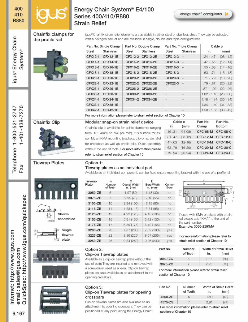
Energy Chain System® E4/100Series 400/410/R880Strain Relief
Part No. Single Clamp Part No. Double Clamp Part No. Triple Clamp Cable ø
Steel Stainless Steel Stainless Steel Stainless in. (mm)
CFX12-1 CFX12-1E CFX12-2 CFX12-2E CFX12-3 – .24 - .47 (06 - 12)
CFX14-1 CFX14-1E CFX14-2 CFX14-2E CFX14-3 – .47 - .55 (12 - 14)
CFX16-1 CFX16-1E CFX16-2 CFX16-2E CFX16-3 – .55 - .63 (14 - 16)
CFX18-1 CFX18-1E CFX18-2 CFX18-2E CFX18-3 – .63 - .71 (16 - 18)
CFX20-1 CFX20-1E CFX20-2 CFX20-2E CFX20-3 – .71 - .79 (18 - 20)
CFX22-1 CFX22-1E CFX22-2 CFX22-2E CFX22-3 – .79 - .87 (20 - 22)
CFX26-1 CFX26-1E CFX26-2 CFX26-2E – – .87 - 1.02 (22 - 26)
CFX30-1 CFX30-1E CFX30-2 CFX30-2E – – 1.02 - 1.18 (26 - 30)
CFX34-1 CFX34-1E CFX34-2 CFX34-2E – – 1.18 - 1.34 (30 - 34)
CFX38-1 CFX38-1E – – – – 1.34 - 1.50 (34 - 38)
CFX42-1 CFX42-1E – – – – 1.50 - 1.65 (38 - 42)
Chainfix clamps forthe profile rail
Tiewrap Plates
igus® Chainfix strain relief elements are available in either steel or stainless steel. They can be adjustedwith a hexagon socket and are available in single, double and triple configurations.
Option 2:Clip-on Tiewrap platesAvailable as a clip-on tiewrap plate without theuse of bolts They are inserted and removed witha screwdriver used as a lever. Clip-on tiewrapplates are also available as an attachment to theopening crossbars.
Option 3:Clip-on Tiewrap plates for openingcrossbarsClip-on tiewrap plates are also available as anattachment to opening crossbars. They can bepositioned at any point along the Energy Chain®.
Option 1:Tiewrap plates as an individual partAvailable as an individual component, can be fixed onto a mounting bracket with the use of a profile rail.
B
C
90°
(n-1) x .39 (10)
.08 (2).31(8)
.71 (18)
1.73
(44).47 (12)
.08
(2)
.24
(6.2
)
.47 (12)
.24
(6)
.31
(8)
.08
(2)
1.10(28)
1.38 (35)
Singletiewrapplate
Shownassembled
Tiewrap n C B Plate Number Overall Width Bore Width Center
of Teeth in. (mm) in. (mm) Bore
3050-ZB 5 1.97 (50) 1.18 (30) no
3075-ZB 7 2.95 (75) 2.16 (55) no
3100-ZB 10 3.94 (100) 3.15 (80) no
3115-ZB 11 4.53 (115) 3.74 (95) no
3125-ZB 12 4.92 (125) 4.13 (105) no
3150-ZB 15 5.91 (150) 5.12 (130) no
3175-ZB 17 6.89 (175) 6.10 (155) no
3200-ZB 20 7.87 (200) 7.09 (180) yes
3225-ZB 22 8.86 (225) 8.07 (205) yes
3250-ZB 25 9.84 (250) 9.06 (230) yes
Part No. Number Width of Strain Reliefof Teeth in. (mm)
3050-ZC 5 1.97 (50)
3075-ZC 7 2.95 (75)
Part No. Number Width of Strain Reliefof Teeth in. (mm)
4550-ZS 5 1.89 (48)
4575-ZS 7 2.91 (74)For more information please refer to strain reliefsection of Chapter 10
For more information please refer to strain reliefsection of Chapter 10
For more information please refer to strain relief section of Chapter 10
Cable ø Part No. Part No.in. (mm) Clamp Bottom
.16-.31 (04-08) CFC-08-M CFC-08-C
.31-.47 (08-12) CFC-12-M CFC-12-C
.47-.63 (12-16) CFC-16-M CFC-16-C
.63-.79 (16-20) CFC-20-M CFC-20-C
.79-.94 (20-24) CFC-24-M CFC-24-C
Modular snap-on strain relief deviceChainfix clip is available for cable diameters ranging
from .16” (4mm) to .94” (24 mm). It is suitable for as-
sembly on KMA mounting brackets, clip-on strain relief
for crossbars as well as profile rails. Quick assembly
without the use of tools. For more information please
refer to strain relief section of Chapter 10
Chainfix Clip
For more information please refer tostrain relief section of Chapter 10
If used with KMA brackets with profilerail please add “KMA” to the end ofthe part number.Example: 3050-ZBKMA
energy chain® configurator
® 400410
R880
6.168
PD
F:
ww
w.ig
us.
com
/e-c
hai
n-p
dfs
Sp
ecs/
CA
D/R
FQ
: w
ww
.igu
s.co
m/e
-ch
ain
sR
oH
S in
fo:
ww
w.ig
us.
com
/Ro
HS
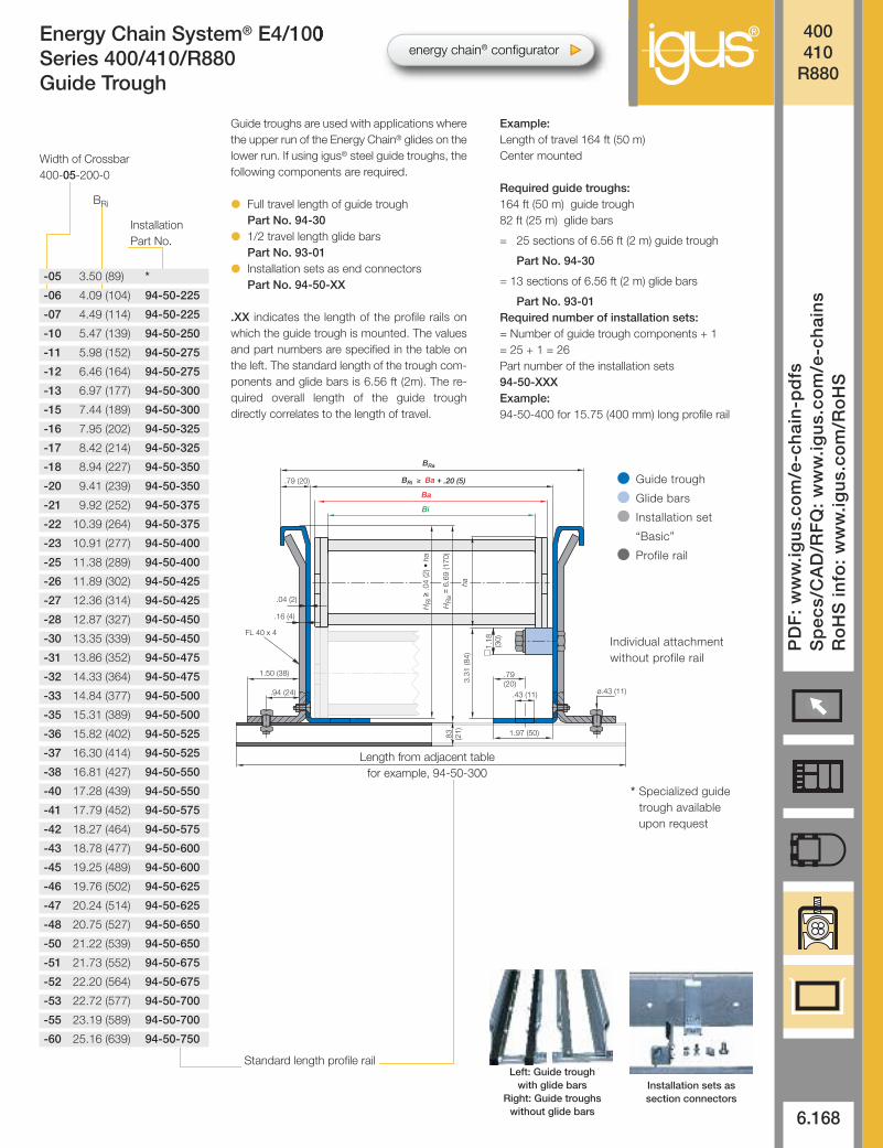
Energy Chain System® E4/100Series 400/410/R880Guide Trough
Guide troughs are used with applications wherethe upper run of the Energy Chain® glides on thelower run. If using igus® steel guide troughs, thefollowing components are required.
● Full travel length of guide troughPart No. 94-30
● 1/2 travel length glide barsPart No. 93-01
● Installation sets as end connectorsPart No. 94-50-XX
.XX indicates the length of the profile rails onwhich the guide trough is mounted. The valuesand part numbers are specified in the table onthe left. The standard length of the trough com-ponents and glide bars is 6.56 ft (2m). The re-quired overall length of the guide trough directly correlates to the length of travel.
Example: Length of travel 164 ft (50 m)Center mounted
Required guide troughs:164 ft (50 m) guide trough82 ft (25 m) glide bars
= 25 sections of 6.56 ft (2 m) guide trough
Part No. 94-30
= 13 sections of 6.56 ft (2 m) glide bars
Part No. 93-01Required number of installation sets:= Number of guide trough components + 1= 25 + 1 = 26Part number of the installation sets94-50-XXXExample:94-50-400 for 15.75 (400 mm) long profile rail
B Ri ≥ Ba +
FL 40 x 4
Bi
Ba
B Ra
.79 (20) .20 (5)
.79 (20)
.94 (24)
1.50 (38)
1.97 (50)
3.31
(84)
1.18
(3
0)
.04 (2)
.16 (4)
.43 (11) ø.43 (11)
ha
.83
(21)
HR
i ≥ .0
4 (2
) • h
a
HR
a =
6.6
9 (1
70)
* Specialized guidetrough availableupon request
Individual attachmentwithout profile rail
Standard length profile rail
Length from adjacent tablefor example, 94-50-300
Width of Crossbar400-05-200-0
BRi
InstallationPart No.
-05 3.50 (89) *
-06 4.09 (104) 94-50-225
-07 4.49 (114) 94-50-225
-10 5.47 (139) 94-50-250
-11 5.98 (152) 94-50-275
-12 6.46 (164) 94-50-275
-13 6.97 (177) 94-50-300
-15 7.44 (189) 94-50-300
-16 7.95 (202) 94-50-325
-17 8.42 (214) 94-50-325
-18 8.94 (227) 94-50-350
-20 9.41 (239) 94-50-350
-21 9.92 (252) 94-50-375
-22 10.39 (264) 94-50-375
-23 10.91 (277) 94-50-400
-25 11.38 (289) 94-50-400
-26 11.89 (302) 94-50-425
-27 12.36 (314) 94-50-425
-28 12.87 (327) 94-50-450
-30 13.35 (339) 94-50-450
-31 13.86 (352) 94-50-475
-32 14.33 (364) 94-50-475
-33 14.84 (377) 94-50-500
-35 15.31 (389) 94-50-500
-36 15.82 (402) 94-50-525
-37 16.30 (414) 94-50-525
-38 16.81 (427) 94-50-550
-40 17.28 (439) 94-50-550
-41 17.79 (452) 94-50-575
-42 18.27 (464) 94-50-575
-43 18.78 (477) 94-50-600
-45 19.25 (489) 94-50-600
-46 19.76 (502) 94-50-625
-47 20.24 (514) 94-50-625
-48 20.75 (527) 94-50-650
-50 21.22 (539) 94-50-650
-51 21.73 (552) 94-50-675
-52 22.20 (564) 94-50-675
-53 22.72 (577) 94-50-700
-55 23.19 (589) 94-50-700
-60 25.16 (639) 94-50-750
Left: Guide troughwith glide bars
Right: Guide troughswithout glide bars
Installation sets assection connectors
Guide trough
Glide bars
Installation set
“Basic”
Profile rail
energy chain® configurator
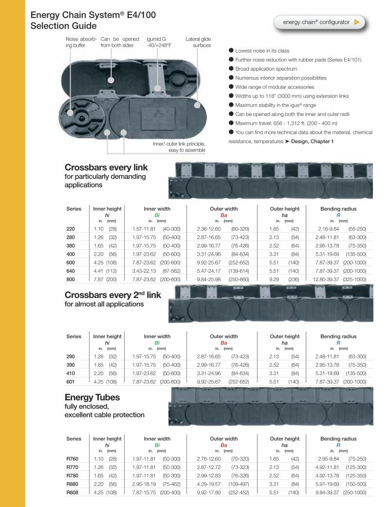
Energy Chain System® E4/100Selection Guide
Noise absorb-ing buffer
igumid G-40/+248°F
Lateral glide surfaces
Can be openedfrom both sides
l Lowest noise in its class
l Further noise reduction with rubber pads (Series E4/101)
l Broad application spectrum
l Numerous interior separation possibilities
l Wide range of modular accessories
l Widths up to 118” (3000 mm) using extension links
l Maximum stability in the igus® range
l Can be opened along both the inner and outer radii
l Maximum travel: 656 - 1,312 ft. (200 - 400 m)
l You can find more technical data about the material, chemical
resistance, temperatures ‰ Design, Chapter 1
Crossbars every linkfor particularly demandingapplications
Series Inner height Inner width Outer width Outer height Bending radius hi Bi Ba ha R
in. (mm) in. (mm) in. (mm) in. (mm) in. (mm)
220 1.10 (28) 1.57-11.81 (40-300) 2.36-12.60 (60-320) 1.65 (42) 2.16-9.84 (55-250)
280 1.26 (32) 1.97-15.75 (50-400) 2.87-16.65 (73-423) 2.13 (54) 2.48-11.81 (63-300)
380 1.65 (42) 1.97-15.75 (50-400) 2.99-16.77 (76-426) 2.52 (64) 2.95-13.78 (75-350)
400 2.20 (56) 1.97-23.62 (50-600) 3.31-24.96 (84-634) 3.31 (84) 5.31-19.69 (135-500)
600 4.25 (108) 7.87-23.62 (200-600) 9.92-25.67 (252-652) 5.51 (140) 7.87-39.37 (200-1000)
640 4.41 (112) 3.43-22.13 (87-562) 5.47-24.17 (139-614) 5.51 (140) 7.87-39.37 (200-1000)
800 7.87 (200) 7.87-23.62 (200-600) 9.84-25.98 (250-660) 9.29 (236) 12.80-39.37 (325-1000)
Crossbars every 2nd linkfor almost all applications
Series Inner height Inner width Outer width Outer height Bending radius hi Bi Ba ha R
in. (mm) in. (mm) in. (mm) in. (mm) in. (mm)
290 1.26 (32) 1.97-15.75 (50-400) 2.87-16.65 (73-423) 2.13 (54) 2.48-11.81 (63-300)
390 1.65 (42) 1.97-15.75 (50-400) 2.99-16.77 (76-426) 2.52 (64) 2.95-13.78 (75-350)
410 2.20 (56) 1.97-23.62 (50-600) 3.31-24.96 (84-634) 3.31 (84) 5.31-19.69 (135-500)
601 4.25 (108) 7.87-23.62 (200-600) 9.92-25.67 (252-652) 5.51 (140) 7.87-39.37 (200-1000)
Energy Tubesfully enclosed, excellent cable protection
Series Inner height Inner width Outer width Outer height Bending radius hi Bi Ba ha R
in. (mm) in. (mm) in. (mm) in. (mm) in. (mm)
R760 1.10 (28) 1.97-11.81 (50-300) 2.76-12.60 (70-320) 1.65 (42) 2.95-9.84 (75-250)
R770 1.26 (32) 1.97-11.81 (50-300) 2.87-12.72 (73-323) 2.13 (54) 4.92-11.81 (125-300)
R780 1.65 (42) 1.97-11.81 (50-300) 2.99-12.83 (76-326) 2.52 (64) 4.92-13.78 (125-350)
R880 2.20 (56) 2.95-18.19 (75-462) 4.29-19.57 (109-497) 3.31 (84) 5.91-19.69 (150-500)
R608 4.25 (108) 7.87-15.75 (200-400) 9.92-17.80 (252-452) 5.51 (140) 9.84-39.37 (250-1000)
Inner/-outer link principle, easy to assemble
energy chain® configurator
E4/1
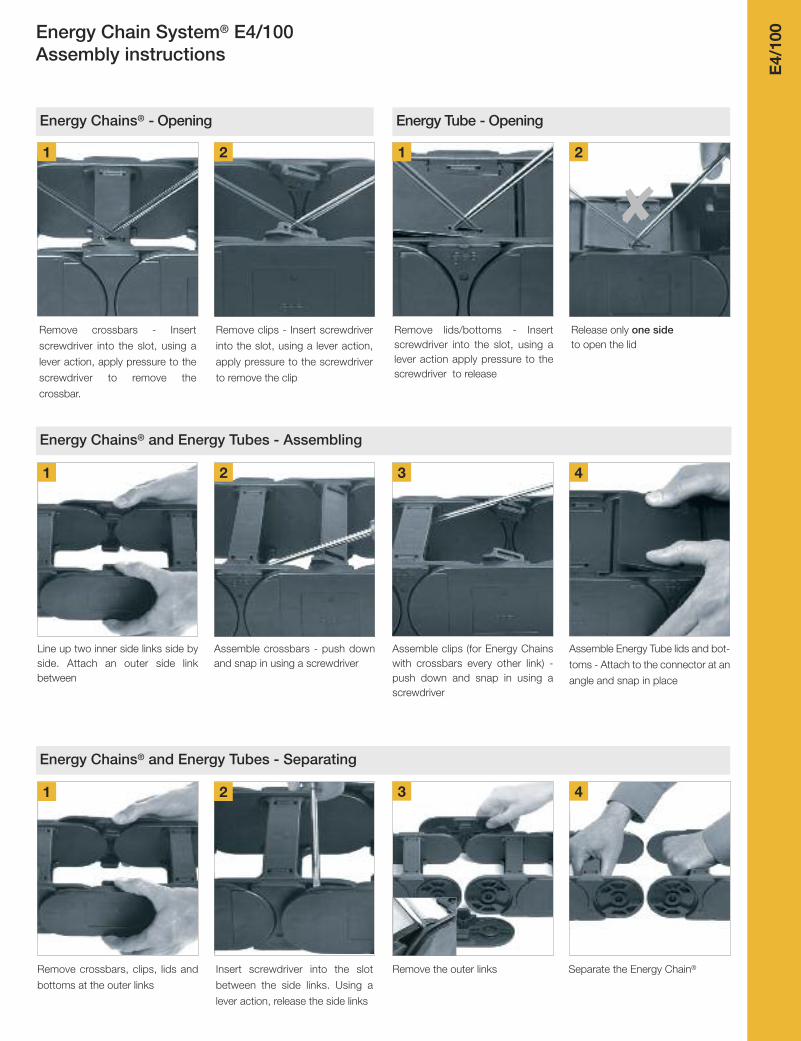
00Energy Chain System® E4/100
Assembly instructions
1 2 3 4
1 2 3 4
Release only one side to open the lid
Energy Chains® and Energy Tubes - Assembling
Line up two inner side links side byside. Attach an outer side linkbetween
Assemble crossbars - push downand snap in using a screwdriver
Assemble clips (for Energy Chainswith crossbars every other link) -push down and snap in using ascrewdriver
Assemble Energy Tube lids and bot-
toms - Attach to the connector at an
angle and snap in place
Energy Chains® and Energy Tubes - Separating
Remove crossbars, clips, lids and
bottoms at the outer links
Remove lids/bottoms - Insertscrew driver into the slot, using alever action apply pressure to thescrewdriver to release
Insert screwdriver into the slot
between the side links. Using a
lever action, release the side links
Remove crossbars - Insert
screwdriver into the slot, using a
lever action, apply pressure to the
screwdriver to remove the
crossbar.
Remove clips - Insert screwdriver
into the slot, using a lever action,
apply pressure to the screwdriver
to remove the clip
Remove the outer links Separate the Energy Chain®
1 2
Energy Chains® - Opening
1 2
Energy Tube - Opening
8
![CHROMA METER CR-400/410Catalog] CR-400.pdf · 2020. 5. 13. · CR-400_outside.ai 2016.2.22 23 CHROMA METER ˜CR-400/410 CR-400 CR-410 217 40.2 32 100 255 73 Data Processor DP-400](https://img.pdfslide.net/doc/110x75/60cb27bfea0b0036f227a1f4/chroma-meter-cr-400-catalog-cr-400pdf-2020-5-13-cr-400outsideai-2016222.jpg)