Embed Size (px)
Citation preview

MSc. Polymer Engineering
Project Report
SESSION 2014-2015
TITLE
Developing Polymer composite manhole cover using waste and recycled materials
Author Supervisor
Amit Kumar Rana Dr. Mike Barker
40135619
1

ACKNOWLEDGEMENTS
The writing of this dissertation has been one of the most significant academic
challenges I have ever had to face. Without the support, patience and guidance of
the following people, this study would not have been completed. It is to them that I
owe my deepest gratitude.
Foremost, I would like to express my sincere gratitude to my supervisor Dr. Mike
Barker for the continuous support of my M.Sc. project, for his patience, motivation,
enthusiasm, and immense knowledge. His guidance helped me in all the time of
research and writing of this dissertation. I could not have imagined having a better
supervisor and mentor for my M.Sc. project.
Besides my supervisor, I would like to thank the rest of my project members: Lynn
Chalmers, Professor Nick Christofi for their encouragement and insightful comments.
2

ABSTRACT
This work cover studies on manufacturing of manhole covers using recycled
polymeric waste materials such as glass fibre and rubber particles along with
thermoset epoxy resin used as matrix material. Surface treated rubber particles were
used which was done by using vinyltrimethoxysilane coupling agent. The mixture of
epoxy resin along with rubber particles and glass fibre was poured into moulds to
obtain mechanical test specimens. After curing of epoxy resin mechanical tests such
as tensile test, charpy impact test and 3-point bend test were performed and results
were analysed. Throughout the study, changes in mechanical properties were
observed on increasing the weight percentage of rubber particles and powdered
glass fibre. At starting, neat epoxy was not completely brittle and to find out that DSC
was also performed with no significant result; but upon adding recycled glass fibre
powder the sample cracked in a very brittle manner and also the tensile modulus
along with other tensile properties was drastically decreased. Therefore, particles of
recycled rubber was added to improve some ductility of prepared sample and the
results were impressive; tensile strength, impact toughness, and fracture toughness
all were increased to the approximate level of neat epoxy test values. With 10% 16
mesh size rubber particles and 30% powdered glass fibre, which was then kept in
compression moulding machine gave the best results among all the other
formulations. Similarly, with increasing the rubber content by 20% and lowering the
glass fibre content from 30% to 25% good results were obtained.
3

LIST OF SYMBOLS AND ABBREVIATIONS
GF glass fibre
CM compression moulding
HF heating off
HO heating on
R rubber
PMMA poly(methylmethacrylate)
PET poly(ethleneterephthalate)
t.s. Tensile strength
min. Minimum
PP Polypropylene
GRP Glass reinforced polymer
4

Table of Contents
1. INTRODUCTION.........................................................................................................................6
2. LITERATURE REVIEW.............................................................................................................8
2.1 Recycled rubber particles in concrete..............................................................................8
2.2 Recycled rubber particles in polymers.............................................................................9
2.3 Recycled glass fibre in polymers.....................................................................................10
3. EXPERIMENTAL......................................................................................................................11
3.1 Materials.................................................................................................................................11
3.2 Processing.............................................................................................................................12
3.3 Characterisation...................................................................................................................14
4. RESULTS..................................................................................................................................16
4.1 Tensile test.......................................................................................................................16
4.2 Charpy impact test.........................................................................................................18
4.3 3-point bend test.............................................................................................................19
5. DISCUSSION............................................................................................................................20
6. CONCLUSION..........................................................................................................................26
7. RECOMMENDATIONS............................................................................................................26
8. REFERENCES..........................................................................................................................27
9. BIBLIOGRAPHY.......................................................................................................................28
5

1. INTRODUCTION
Iron is used in most of the application due to its low price and abundant
availability in nature. Cast iron provides high durability and a strong product capable
to bear high load and severe impacts. But there is problem on using cast iron in open
environment, it get easily corroded, and also to maintain those high mechanical
properties product always becomes too heavy which causes problems to the
workers, as metal is a good electrical conductor it can be electrocuted which can
cause death in extreme conditions and also due to high resale value of cast iron it is
very attractive to thefts. To tackle these problems polymer composites can be used
instead of cast iron as these composites has either very low or zero scrap value.
Epoxy is one of the available thermoset polymer which can be used in place of cast
iron to prepare street furniture’s such as manhole covers, lamp posts, benches etc.
where it could last long in harsh environments very easily. As like cast iron there is a
problem with epoxies as well, that they are very brittle in nature; but this can be
substantially overcome by using recycled rubber particles which reduces the
brittleness of epoxy resin.
There are some studies that already have been carried out successfully with
positive results showing improvements in mechanical performances. In one study it
is mentioned that using homogenous and treated fine rubber particles improves
mechanical performance than using coarse and untreated rubber particles; and an
optimum concentration should be determined for the desired modifications because
using more than 25% volume treated rubber particles decreases the mechanical
performance of epoxy.
6

The main objective of this research is to find the possibilities of blending three
(epoxy, recycled rubber particles and powdered glass fibre) non-compatible
materials into a homogenous mixture while investigating the potential filler, and
developing the formulation so that it could exhibit the required properties which
needed to prepare manhole covers specifically. According to British standard BS EN
124-1994 manhole tops are divided into the following classes:
Group 1 (min. class A 15) – areas which can be used by pedestrians and
pedal cyclists.
Group 2 (min. class B 125) – footways, pedestrian areas and comparable
areas, car parks or car parking decks.
Group 3 (min. class C 250) – for manhole tops installed in the area of
kerbside channels of roads which when measured from the kerb edge, extend
a maximum of 0.5 m into the carriageway and a maximum of 0.2 m into the
footway.
Group 4 (min. class D 400) – carriageways of roads (including pedestrian
streets), hard shoulders and parking areas, for all types of road vehicles.
Group 5 (min. class E 600) – areas imposing high wheel loads, e.g. docks,
aircraft pavements.
Group 6 (class F 900) – areas imposing particularly high wheels loads, e.g.
aircraft pavements. (STANDARD, 1994)
7

2. LITERATURE REVIEW
2.1 Recycled rubber particles in concrete
Several researchers have worked on the recycling and reclamation methodologies of
waste rubber products to make them reusable for engineering applications. One
study has focussed on the use of shredded or ground rubber, without
devulcanization, in secondary products. Significant amount of work have been done
on the mixing of recycled rubber particles inside concrete, bitumen and asphalt to
make products appropriate for structural applications. The brittle nature of concrete
and its low loading toughness has initiated the use of rubber particles to remedy
these drawbacks. Several studies discussed the properties and performances of
concrete mixed with high volume of crumb rubber from scrap tires. All of them
demonstrated promising mechanical properties and enhanced performance by the
use of crumb rubberized concrete. Another common trend investigated by all of the
researchers was considerable deformation undergone by concrete before failure and
its capability to withstand post-failure loads. All of these studies reveal a dependence
of properties on the rubber particle size along with an increase in failure temperature.
The biggest common advantage depicted by all of these studies had been the ease
of fabricating crumb rubberized products for structural applications. In spite of all
these advantages, some drawbacks were also seen. Fattuhi et al. analysed the
properties of cement-based materials containing shredded scrap truck tire rubber
and got reduced compressive properties and densities of cement by the use of
rubber. Fenner et al. discussed the environmental and structural implications for the
reuse of tires in fluvial and marine construction. They showed that leaching of
different chemical compounds like zinc, cadmium and carbon black results in the
8

degradation of rubber tires and limits their use for marine applications, especially in
sea water and proposed one corrective measure for the same. In addition,
researchers found increased water permeability in the concrete mixtures by the
addition of rubber particles. (BHADRA, 2010)
2.2 Recycled rubber particles in polymers
Rubber particles have been found to be usable in polymeric matrix as well.
Elastic rubber particles are expected to absorb large impact energy through plastic
deformation of the particles. Rubber particles would also promote crack pinning and
crack bridging. These mechanism should lead to higher toughness in rubber
reinforced polymers. Researchers have observed that the processing method,
rubber particle size, and size distribution are important parameters in affecting
rubber–matrix adhesion and material properties. (BHADRA, 2010)
Using the resin transfer method, Structural Science Composite (SSC) said its
composite design produced covers which were “typically three to four times lighter
than an equivalent steel or reinforced concrete cover, yet still provides the long term
performance and mechanical properties required for this type of application”. The
group said this included very high load bearing capabilities to meet BS EN124:1994
Standards Group 4 Class D400, which specifies an access cover must be able to
cope with static loading from cars, vans, lorries and HGVs if installed on roads, hard
shoulders, factory sites or industrial estates. To pass BS EN124 Class D400 an
access cover or grating must withstand a 40 tonne test load. (staff, 2015)
9

2.3 Recycled glass fibre in polymers
Recycling of fibre reinforced polymers is an important area of research for
manufacturers to invest in. There are two types of FRP matrices: thermosetting and
thermoplastic. Thermoplastic resin matrixes are held together by weak Van-der-Waal
bonds which break when heated and “reconnect” when cooled. This section mainly
focuses on the recycling of FRP with a thermosetting matrix which presents a
problem when recycling because it cannot be melted and reformed. Thermosets
require a chemical reaction know as curing to convert liquid resin into a solid polymer
component. Curing involves a cross-linking process which occurs at a particular
temperature when a hardener initiates the cross-linking process. Cross-linking is the
reason thermosets cannot be melted and re-solidified to form new components.
Thermosetting resins are used as matrixes instead of thermoplastic resin matrixes
because the cross-linking process of the resin means that solid structures produced
are often stronger than any thermoplastic. They are also much better suited to higher
temperature applications because they do not soften or creep significantly when
heated. Thermosetting FRP are often specialist and require properties from the
thermoset that thermoplastics cannot match. Effective recycling of thermosetting
FRP is important so thermosetting composites can be continually used without a
huge impact on the environment. There are four main recycling techniques for
thermosetting FRP; size reduction, thermal degradation, chemical degradation and
energy recovery. Information on these four different recycling processes can be seen
in appendix 1. (Wait, 2010)
10

3. EXPERIMENTAL
3.1 Materials
The epoxy resin used, was in liquid form provided by Gurit named SP106
(bisphenol-A-(epichlorhydrin) epoxy resin). The hardener used was slow hardener
also provided by Gurit, and no accelerator was used to decrease the curing time.
Rubber particles of different sizes were provided by Recyclatech Group Limited of
different mesh sizes (2mesh, 6mesh, 8mesh, 12mesh, 16mesh) which was derived
from truck tyre buffing’s. For surface treatment of these recycled rubber particles
vinyltrimethoxysilane was used to enhance bonding in between rubber and epoxy
resin. Recycled Glass fibre which was used provided by Filon in powder form, having
a fibre lengths ranging from 18mm (shredded) to 1700 microns (M10) to 375 microns
(M40). Table 1 has the composition of different ingredients which were present in the
powdered recycled glass fibre.
Table 1. Composition of Filon GRP Filler
Product Name %
Glass Fibre ≥30
Aluminium Trihydrate ≥5
Polyester Resin ≥60
Polyester Film ≥0.2
Nylon ≥0.05
11

3.2 Processing
Casting is a manufacturing process by which a liquid material is usually
poured into a mould, which contains a hollow cavity of the desired shape, and then
allowed to solidify. The solidified part is also known as a casting, which is ejected or
broken out of the mould to complete the process. Casting materials are usually
metals or various cold setting materials that cure after mixing two or more
components together; examples are epoxy, concrete, plaster and clay. Casting is
most often used for making complex shapes that would be otherwise difficult or
uneconomical to make by other methods. (DeGarmo, 2003)
The mixing ratio of the epoxy and hardener was kept constant for all
experiments as 100:18 by weight respectively. To prepare neat epoxy sample, epoxy
and hardener was mixed in a plastic container made up off PP with the help of a pop
sickle stick and then the mixture was poured into a mould made up of metal. But
before that a PET film was placed onto the metal surface and Macwax named
releasing agent was sprayed onto that PET film and left for 2 minutes untouched, so
that the prepared sample would not stick to film and comes off easily from mould.
The whole system was hold together by the help of paper clips so that the mixture
does not flow outside from the mould. Then, another sample was prepared by using
8 mesh size recycled rubber particles along with epoxy to enhance the mechanical
properties of cured epoxy resin. This time mixing was done using an electric stirrer
having a propeller kind of attachment and mixing was followed by 2 minutes then the
mixture was poured into the metal mould. Similarly, another sample was casted but
this time instead of 8 mesh rubber 16 mesh size recycled rubber particles and
recycled powdered glass fibre were incorporated along with epoxy resin then this
mixture was poured into two different mould one was made up of metal and another
12
was made up of PMMA. The details of all different formulations with varying
components is discussed below in table 2. This whole processing was carried out at
room temperature (17-19oC). But at this very low temperature some problems came
into view which are discussed further in details in discussion section of report.
Therefore, to tackle these problems some changes were done at processing stage.
Firstly, the sample was placed onto the hot surface of oven hoping that it will
increase the temperature of the mould and problem could be overcome; but with no
luck, problem still persisted. Hence, for second time the sample was kept into
vacuum oven while the heating was off. But still no appropriate results were obtained
and for the third but not the last time sample was kept into vacuum oven with heating
maintained around 40oC. As these changes in processing conditions did not provided
desirable samples. Then at last, keeping the sample into the compression moulding
was decided under some pressure and temperature. Therefore, an another metal
plate was prepared having another PET film pasted onto the surface of metal and
each time Macwax named releasing agent was sprayed onto the whole mould
assembly so that no problems would have to face to release the prepared sample
from the mould. As the mixture was poured into the moulds another metal plate was
kept onto that and by keeping both casting samples upon each other, the whole
assembly was kept into the compression moulding machine; where the samples
were under high pressure (15KN) and normal temperature ranging from 33oC to
40oC.
13

3.3 Characterisation
In this study, tension, impact and fracture toughness tests were performed in
order to determine the mechanical properties of rubber and glass fibre modified
epoxy resin. For tensile test, specimen with gauge length (55mm), width (3.58mm-
5.25mm) and thickness of 10.1mm were used. For charpy impact test, 2mm
notched bars were used having breadth (3.88mm-4.64mm) and width (8.08mm-
9.10mm). For 3-point bend test long bar like samples having breadth (3.58mm-
5.23mm) and width (9.48mm-10.92mm) were used. To perform these tests Zwick
Roell machines were used having load cells of 30KN and 50KN for tensile and 3-
point bend tests respectively; and for charpy impact test 5J hammer was used to
calculate the impact resistance of 2mm notched samples.
In order to obtain these samples, different formulations were used by varying mainly
the rubber and glass fibre loading percentage and all these formulations were
followed by a mixing time of at least 2 min and maximum of 5 min according to mix-
ability of rubber and glass fibre into epoxy resin and those different formulations are
mentioned below in table 2.
14

Table 2. Description of the Formulations used
Epoxy
Resin
(g)
Slow
Hardener
(g)
Rubber
(g)
Vinyltrimethoxy-
-silane
(g)
Glass
fibre
(g)
Formulation 1 45.8 10 3 (8 mesh) 1.2 0
Formulation 2 45.9 10.1 0 0 14
Formulation 3 53.4 11.7 3.5 (16 mesh) 1.4 0
Formulation 4 41.9 9.2 3.5 (16 mesh) 1.4 14
Formulation 5 50.5 11.1 3.5 (16 mesh) 1.4 3.5
Formulation 6 47.6 10.5 3.5 (16 mesh) 1.4 7
Formulation 7 36.2 8.0 3.5 (16 mesh) 1.4 21
Formulation 8 33.3 7.3 7 (16 mesh) 1.4 21
Formulation 9 30.4 6.7 10.5 (16 mesh) 1.4 21
Formulation 10 30.4 6.7 14 (16 mesh) 1.4 17.5
Formulation 11 47.6 10.5 10.5 (16 mesh) 1.4 0
15

4. RESULTS
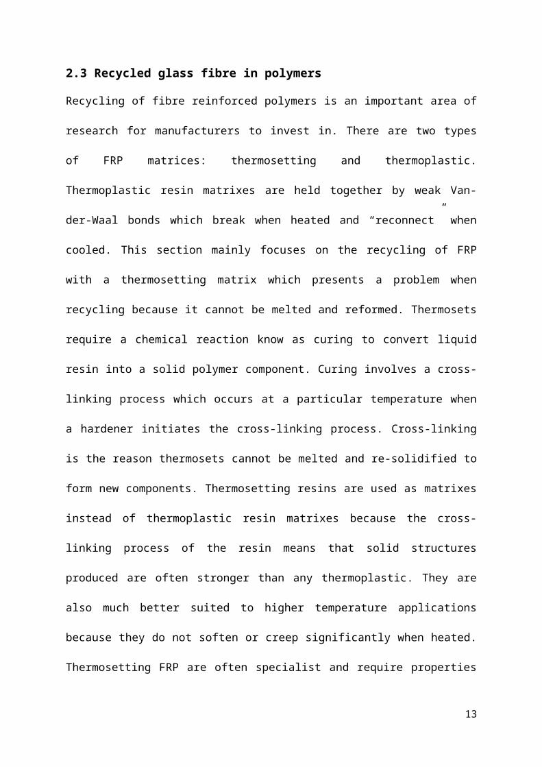
4.1 Tensile test
Tensile properties of recycled rubber and glass fibre modified epoxy are
presented in Table 3 as tensile modulus, tensile yield, tensile strength, elongation at
t.s., stress at break and strain at break. This SP106 epoxy has ductile nature,
because during tensile testing it gave yield point which was a strange behaviour, as
epoxies are generally brittle in nature and does not give yield points. Similarly,
strange behaviour can be seen with increasing powdered recycled glass fibre
concentration and keeping rubber content constant at 5 percent. These all differently
behaving properties are further discussed in details in discussion section of report.
Materialcomposites
Tensile modulus
MPa
Tensile Yield
MPa
Tensile strength
MPa
Elongation at T.S. %
Stress at break MPa
Strain at break %
Width
mm
Thickness
mm
Area
mm2
Epoxy 711 52.5 52.5 9.9 40.8 11.8 3.58 10.1 36.16Epoxy+5%R 296 21.2 21.2 8.9 15.1 11.0 3.91 10.1 39.44Epoxy+5%R+5%GF
499 25.5 5.9 24.9 5.9 4.538 10.1 45.83
Epoxy+5%R+10%GF
383 19.7 4.8 19.6 4.8 4.018 10.1 40.58
Epoxy+5%R+20%GF
273 13.9 13.9 7.8 11.8 13.1 4.1 10.1 41.41
Epoxy+5%R+30%GF+hf
303 13.1 4.5 12.8 4.5 5.25 10.1 53.03
Epoxy+5%R+30%GF+ho
468 13.5 3.1 13.2 3.1 4.293 10.1 43.35
Epoxy+10%R+30%GF+CM
625 21.3 3.8 21.2 3.8 4.07 10.1 41.11
Epoxy+15%R+30%GF+CM
546 17.3 3.9 17.2 3.9 4.13 10.1 41.71
Epoxy+20%R+25%GF+
393 15.6 4.4 15.2 4.4 4.045 10.1 40.85
16

CMEpoxy+15%R
242 13.4 13.4 7.0 12.2 7.6 4.073 10.1 41.14
Table 3. Tensile test results
4.2 Charpy impact test
Charpy impact test results are presented in Table 4 as impact resistance values.
On considering the obtained results, it is shown clearly that upon adding rubber
particles into epoxy resin during processing increases the impact resistance of epoxy
resin. Whereas, addition of powdered glass fibre decreases impact resistance.
Table 4. Charpy impact test results
Material composite bmm
hmm
I.R.KJ/m2
Epoxy 4.15 8.13 6.97Epoxy+5%R 4.59 8.20 3.03
Epoxy+5%R+5%GF 4.64 9.10 1.53
Epoxy+5%R+10%GF 4.24 8.95 1.73
Epoxy+5%R+30%GF+hf 4.56 8.14 1.8
Epoxy+5%R+30%GF+ho 4.31 8.78 1.55
17

Epoxy+10%R+30%GF+CM 3.91 8.44 5.18
Epoxy+15%R+30%GF+CM 3.88 8.08 50.45
Epoxy+20%R+25%GF+CM 4.1 8.16 217.83
Epoxy+15%R 4.55 8.11 241.57
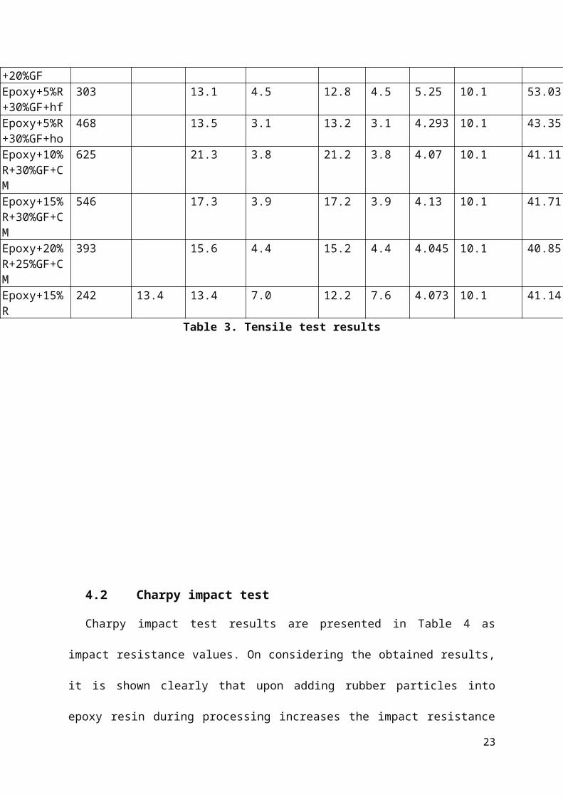
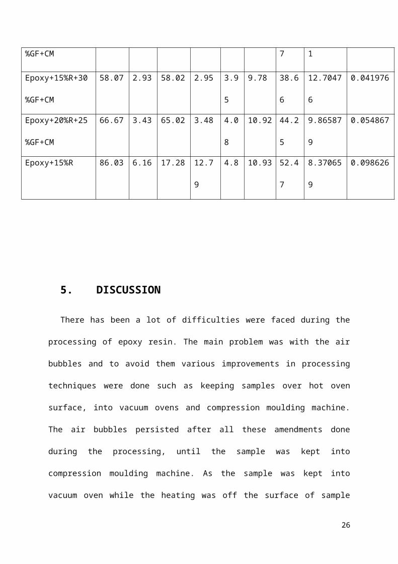
4.3 3-point bend test
The results for 3-point bend test are presented in table 5 and these results are
much similar to impact test results. On addition of more recycled rubber particles the
sample became more flexible and upon adding powdered recycled glass fibre the
sample becomes stiffer and gave very low force bearing values.
Table 5. 3-point bend test results
Material
compostites
Fmax
N
dL at
Fmax
mm
Fbreak
N
dL at
break
mm
a0
mm
b0
mm
S0
mm
flexural
stress
KN/mm2
maximum
strain
Epoxy 153 6.97 124.45 10.09 4.17 9.48 39.57 12.80821 0.09679
Epoxy+5%R 110.56 6.03 109.63 6.4 4.58 9.77 44.21 10.9796 0.086298
Epoxy+5%R+5%G
F
108 8 106 8.3 4.85 11.25 54.56 7.819779 0.131836
Epoxy+5%R+10%
GF
49.2 10.5 47.7 11.9 3.58 10.82 38.73 11.45259 0.166421
18

Epoxy+5%R+30%
GF+hf
66.3 5 63.7 5.1 5.23 10.52 55.08 8.292931 0.077051
Epoxy+5%R+30%
GF+ho
43.6 4 42.2 4.1 4.29 10.53 45.18 10.09084 0.061699
Epoxy+10%R+30
%GF+CM
62.23 3.13 61.78 3.18 4 9.94 39.77 12.14531 0.045575
Epoxy+15%R+30
%GF+CM
58.07 2.93 58.02 2.95 3.95 9.78 38.66 12.70476 0.041976
Epoxy+20%R+25
%GF+CM
66.67 3.43 65.02 3.48 4.08 10.92 44.25 9.865879 0.054867
Epoxy+15%R 86.03 6.16 17.28 12.79 4.8 10.93 52.47 8.370659 0.098626
5. DISCUSSION
There has been a lot of difficulties were faced during the processing of epoxy
resin. The main problem was with the air bubbles and to avoid them various
improvements in processing techniques were done such as keeping samples over
hot oven surface, into vacuum ovens and compression moulding machine. The air
bubbles persisted after all these amendments done during the processing, until the
sample was kept into compression moulding machine. As the sample was kept into
vacuum oven while the heating was off the surface of sample became very rough
and all the air bubbles were trapped onto upper surface generating stress
19

concentrators all over of the sample; even when the heating was switched on air
bubbles remained in samples. As like the PET film was kept on lower surface during
casting; similarly another PET film was kept onto the upper surface. This time there
were no air bubbles in sample but all the rubber particle came onto the upper surface
and also keeping the PET film on upper surface was very difficult because air was
trapping in between and were creating big air bubbles instead of smaller ones.
Therefore, at last compression moulding machine was used at some elevated
temperature (40oC) than the room temperature. The curing time of epoxy was 4
hours because slow hardener was used instead of fast as slow hardener diminishes
the creep properties of epoxy, and also high temperature could not be used as well
because this would have decreased the viscosity and all the rubber particles might
be migrated to lower surface leaving very bad dispersion and distribution of the
particles. But high pressure was used so that obtained sample would have been very
compact, having high density. When 8 mesh size recycled rubber particles were
used the dispersion and distribution of the rubber particles was not very good and
also did not possess any significant improvement in mechanical properties of
modified epoxy resin. Therefore, in all formulations smaller particles i.e. 16 mesh
size recycled rubber crumbs were used. The critical point for mixing of rubber
particles and glass fibre with epoxy resin while making a composite was 15% and
30% respectively. If there is any need to increase the rubber loading percentage
then the glass fibre loading percentage will decrease for obtaining appropriate
dispersion and distribution of the particles into the mixture. Otherwise, there will be a
problem in mixing all three components into each other and then spreading the
prepared mixture into mould for casting.
20

On comparing the tensile modulus values of virgin epoxy with modified epoxy
there is a drastic decrease in that as epoxy is brittle material and upon adding rubber
into that it becomes less brittle hence the stiffness of epoxy decreases.
Chart 1. Tensile modulus
But other properties were changing in a positive aspect such as impact toughness,
flexural stress and flexural strain.
Similarly, on comparing tensile strength results there is decrement in strength on
increasing the glass fibre content because it makes the product more brittle.
Ep o x y
Ep o x y +5 %R
Ep o x y +5 %R +5 %
G F
Ep o x y +5 %R +1 0 %
G F
Ep o x y +5 %R +2 0 %
G F
Ep o x y +5 %R +3 0 %
G F+h f
Ep o x y +5 %R +3 0 %
G F+h o
Ep o x y +1 0 %R +3 0 %
G F +C M
Ep o x y +1 5 %R +3 0 %
G F +C M
Ep o x y +2 0 %R +2 5 %
G F +C M
Ep o x y +1 5 %R
52.5
21.2 25
.5
19.7
13.9
13.1
13.5 21
.3
17.3
15.6
13.4
tensile test resulttensile strength
Chart 2. Tensile strength
Hence more vulnerable to failure. As the rubber content in the composite reaches a
level of 10% from 5% tensile strength was increased by approximately 8MPa, but
21

upon adding more rubber than this does not make any significance improvement in
tensile strength.
As like other tensile properties stress at break is also related with the loading
percentage of recycled glass fibre and recycled rubber particles.
Ep o x y
Ep o x y +5 %R
Ep o x y +5 %R +5 %
G F
Ep o x y +5 %R +1 0 %
G F
Ep o x y +5 %R +2 0 %
G F
Ep o x y +5 %R +3 0 %
G F+h f
Ep o x y +5 %R +3 0 %
G F+h o
Ep o x y +1 0 %R +3 0 %
G F +C M
Ep o x y +1 5 %R +3 0 %
G F +C M
Ep o x y +2 0 %R +2 5 %
G F +C M
Ep o x y +1 5 %R
40.8
15.1
24.9
19.6
11.8
12.8
13.2
21.2
17.2
15.2
12.2
tensile test resultstress at break
Chart 3. Stress at break
At breaking point maximum bearable stress of 40.8 MPa was given by neat
epoxy resin which was not achieved by any another composite. However, more than
50% stress bearing capability was achieved by 15% rubber & 30% glass fibre and
5% of each rubber & glass fibre contained composites. Whereas, other samples
were able to withstand only 11-15 MPa of stress.
22
Maximum impact resistance were obtained with 15 percent rubber content into
epoxy resin which is quiet acceptable as rubber particles toughen the epoxy by crack
deflection and crack bridging methods of toughening mechanism in composites.
Ep o x y
Ep o x y +5 %R
Ep o x y +5 %R +5 %
G F
Ep o x y +5 %R +1 0 %
G F
Ep o x y +5 %R +3 0 %
G F+h f
Ep o x y +5 %R +3 0 %
G F+h o
Ep o x y +1 0 %R +3 0 %
G F +C M
Ep o x y +1 5 %R +3 0 %
G F +C M
Ep o x y +2 0 %R +2 5 %
G F +C M
Ep o x y +1 5 %R
6.97
3.03
1.53
1.73
1.8
1.55
5.18
50.4
5
217.
83
241.
57
Impact ResistanceImpact Resistance
Chart 4. Impact resistance
But with 20% rubber and 25% glass fibre content results were very good too, by
providing approximately same impact toughness value as with only 15% rubber
content. This happened because of the glass fibre concentration as it was making
the specimen more susceptible to impact failure.
23

Maximum force bearing strength was shown by neat epoxy on comparing all the 3-
point bend test results. There had been a drastic decrease in force bearing ability of
epoxy in all other composites. During testing the composites having 20% and 15%
rubber were cracked but did not split apart showing some positive significance of
added rubber particles. If the deflection at maximum force is also considered then
there is no hierarchy is present in results. But as like tensile test having 10% rubber
and 30% glass fibre gave pretty good result for flexural stress much more close to
neat epoxy values.
Ep o x y
Ep o x y +5 %R
Ep o x y +5 %R +5 %
G F
Ep o x y +5 %R +1 0 %
G F
Ep o x y +5 %R +3 0 %
G F+h f
Ep o x y +5 %R +3 0 %
G F+h o
Ep o x y +1 0 %R +3 0 %
G F +C M
Ep o x y +1 5 %R +3 0 %
G F +C M
Ep o x y +2 0 %R +2 5 %
G F +C M
Ep o x y +1 5 %R
153
110.
56
108
49.2 66
.3
43.6 62
.23
58.0
7
66.6
7 86.0
3
3-point bend test resultFmax
Chart 5. Fmax
24
6. CONCLUSION
After tension, impact resistance and flexural tests studies of modified epoxy with
treated rubber particles and glass fibre, the following conclusions can be drawn:
a) For improved mechanical behaviour the size of rubber particles is very
important; because large size particles do not disperse and distribute very
well as small size particles do.
b) Increasing glass fibre content increases the brittleness of epoxy matrix
causing drastically decreases in mechanical properties but there is a need to
incorporate glass fibre into the epoxy because presence of rubber particles
makes epoxy matrix very flexible having low tensile properties. Therefore, a
considerable amount of both rubber and glass fibre need to add to obtain
desired properties.
7. RECOMMENDATIONS
The further recommendations for this work is to observe the different cracked
sample surfaces under optical microscope so that dispersion of glass fibre
particles, rubber particles and type of cracks can be observed. There is a need to
take the work upon next level by preparing a prototype for which the work has
been carried out to investigate the proper ratio of all materials. The formulation
having 10% rubber and 30% glass fibre content would be a great choice for
further work and also there will be a need to study the mechanical properties of
the prepared prototype in real life scenarios.
25
8. REFERENCES
B.J.P. Jansen, K. T. H. M. P. L., 1999. Preparation of thermoset rubbery epoxy particles as novel toughening modifiers for glassy epoxy resins. Polymer, Volume 40, pp. 5601-5607.
BHADRA, A., 2010. MICROSTRUCTURE–MECHANICAL PROPERTY RELATIONSHIP OF CRUMB RUBBER–POLYURETHANE FOAM COMPOSITES, Oklahoma: s.n.
Cengiz Celikbilek, G. A. C. K., 2004. Modification of Epoxy by a Liquid Elastomer and Solid Rubber Particles. PoIymer BuIIetin, Volume 51, pp. 429-435.
Cevdet Kaynak, C. C. G. A., 2003. Use of silane coupling agents to improve epoxy–rubber interface. European Polymer Journal, Volume 39, pp. 1125-1132.
E. Paul DeGarmo, J. T. B. R. A. K., 2003. MATERIALS AND PROCESS IN MANUFACTURING. 9th ed. s.l.:John Wiley & Sons, Inc.
E. Sipahi-Saglam, C. K. G. A. M. Y. N. A., 2001. Studies on Epoxy Modified With Recycled Rubber. Polymer Engineering And Science , Volume 41, pp. 514-521.
F.G. Smith l, E. D. A. T., 1995. Testing and evaluating commercial applications of new surface-treated rubber technology utilizing waste tires. resources, conservation and recycling, Volume 15, pp. 133-144.
R. BAGHERI, M. A. W. R. A. P., 1997. Use of Surface Modified Recycled Rubber Particles for Toughening of Epoxy Polymers. POLYMER ENGINEERING AND SCIENCE, Volume 37, pp. 245-251.
Song Aiteng, Y. Y., 1990. CTBN-toughened epoxy resins effect of curing mechanism on network structure of the rubber phase. Chinese Journal of Polymer Science, Volume 8, pp. 183-187.
staff, P., 2015. Composites do a good cover-up job. [Online] Available at: http://www.prw.com/subscriber/headlines2.html?id=6281[Accessed 25 04 2015].
STANDARD, B., 1994. Gully tops and manhole tops for vehicular and pedestrian areas - Design requirements, type testing, marking, quality control. Brussels: CEN.
Wait, C. F., 2010. The Reuse and Recycling of Glass Fibre Waste, Birmingham: s.n.
26
9. BIBLIOGRAPHY
B.J.P. Jansen, K. T. H. M. P. L., 1999. Preparation of thermoset rubbery epoxy particles as novel toughening modifiers for glassy epoxy resins. Polymer, Volume 40, pp. 5601-5607.
BHADRA, A., 2010. MICROSTRUCTURE–MECHANICAL PROPERTY RELATIONSHIP OF CRUMB RUBBER–POLYURETHANE FOAM COMPOSITES, Oklahoma: s.n.
Cengiz Celikbilek, G. A. C. K., 2004. Modification of Epoxy by a Liquid Elastomer and Solid Rubber Particles. PoIymer BuIIetin, Volume 51, pp. 429-435.
Cevdet Kaynak, C. C. G. A., 2003. Use of silane coupling agents to improve epoxy–rubber interface. European Polymer Journal, Volume 39, pp. 1125-1132.
E. Paul DeGarmo, J. T. B. R. A. K., 2003. MATERIALS AND PROCESS IN MANUFACTURING. 9th ed. s.l.:John Wiley & Sons, Inc.
E. Sipahi-Saglam, C. K. G. A. M. Y. N. A., 2001. Studies on Epoxy Modified With Recycled Rubber. Polymer Engineering And Science , Volume 41, pp. 514-521.
F.G. Smith l, E. D. A. T., 1995. Testing and evaluating commercial applications of new surface-treated rubber technology utilizing waste tires. resources, conservation and recycling, Volume 15, pp. 133-144.
R. BAGHERI, M. A. W. R. A. P., 1997. Use of Surface Modified Recycled Rubber Particles for Toughening of Epoxy Polymers. POLYMER ENGINEERING AND SCIENCE, Volume 37, pp. 245-251.
Song Aiteng, Y. Y., 1990. CTBN-toughened epoxy resins effect of curing mechanism on network structure of the rubber phase. Chinese Journal of Polymer Science, Volume 8, pp. 183-187.
staff, P., 2015. Composites do a good cover-up job. [Online] Available at: http://www.prw.com/subscriber/headlines2.html?id=6281[Accessed 25 04 2015].
STANDARD, B., 1994. Gully tops and manhole tops for vehicular and pedestrian areas - Design requirements, type testing, marking, quality control. Brussels: CEN.
Wait, C. F., 2010. The Reuse and Recycling of Glass Fibre Waste, Birmingham: s.n.
27

Appendix-1
There is high demand to recycle thermoset materials and mainly there are four main
techniques to recycle thermosetting FRP; chemical degradation, thermal degradation
size reduction and energy recovery.
Chemical degradation – chemical degradation involves the use of chemical
solvents at different temperature which when added to FRP composite cause the
thermosetting matrix to degrade and breakdown so fibres can be recovered.
Chemical recycling requires the use of a chemical solvent to break strong cross-
linking bonds in thermosetting resin. In some cases the organic compound produced
from dissolution of the polymer can be a used for the formulation of new resins.
Dang et al. found bisphenol-F epoxy resin cured with 1, 8-p-menthanediamine would
completely decompose in a nitric acid solution. They used the products obtained
from the chemical decomposition and repolymerized them with an epoxy resin and
curing agent to prepare a recycled resin. Liu et al. used a nitric acid solution at 90 °C
to decompose a bisphenol-A epoxy resin matrix with curing agent IPDA and recover
carbon fibres. Under optimum conditions, epoxy resin was found to decompose
rapidly and it was reported that the fibre appeared unharmed and retained most of
the strength. A urethane-based matrix of scrap end-of-life vehicles with reinforcing
carbon fibres was found to completely degrade using a triethylene glycol/water
solution at temperatures ~240°C and carbon fibres could be recovered. However,
the same treatment was not successful in decomposing an epoxy-based substrate.
Another work completed by Jiang et al. investigated using supercritical n-propanol to
breakdown C-O-C and C-N-C bonds of epoxy resin and obtain long-recycled carbon
fibres maintaining the advantages of continuous structure resulting in high strength.
Supercritical n-propanol was used in a semi-continuous flow reactor with a pressure
28

of 5.2 MPa at 310 °C. Recycled carbon fibre cleaned in an ultrasonic bath of
acetone, followed by a fresh acetone rinse. Resulting carbon fibres had similar
tensile strength and Modulus to as-received carbon fibres with the main difference in
reduction of interfacial bonding strength when recycled fibres were added to epoxy
resin to produce a new composite.
A major disadvantage of using this process is different chemicals and solutions
required to degrade different types of polymer matrix due to different chemical bonds
they can break. Also recovered fibres require washing to remove residual chemicals
and solvents from the surface. There is a large amount of chemical waste produced
during this process making it less environmental friendly. However, this technique
does enable recovery of fibres in continuous form therefore composites produced
using these fibres could potentially achieve higher strengths due to continuous fibres
reducing crack propagation through a composite component. (Wait, 2010)
Thermal degradation - Thermal degradation of FRP matrix is achieved by pyrolysis.
Pyrolysis is the removal of thermosetting resin by thermally degrading the matrix
component of the composite. Pyrolysis involves heating a composite sample to a
moderate temperature in an oxygen-free environment until the volatile organic part
(polymer matrix) decomposes into gases and oils and the inorganic part remains
unchanged (fibres, fillers and char). These can then be recycled back into new
polymeric products with little changes made to the acquired components. Oil and gas
are separated via cooling where they can be collected and fibres are trapped in a
mesh and extracted for use. Oil produced could be added to petroleum or used
directly as a fuel it is also an important source of chemicals which can be used in
other applications. Cunliffe & Williams found oil produced could be used as a viable
fuel when blended with suitable oils to increase the flash point to meet UK and US
29

health and safety legislation. Gas produced could be burnt to power the pyrolysis
system because emissions generated from the combustion of the gas lack toxicity
and hazards that are associated with normal incineration emissions. Recovered
fibres are often covered in char and can require further heating to remove any solid
residue left on the fibres. Fillers such as calcium carbonate can be used again as
fillers in other composites. A study by Torres et al. showed the optimum temperature
for pyrolysis is between 400 ˚C and 500 ˚C. At temperatures above this there was
degradation of the CaCO3 filler and deterioration in properties obtained from fibres
recovered. Temperatures below 400 ˚C resulted in only partial decomposition of the
thermosetting matrix and fibres could not be removed. Torres et al. found the sample
only had to be held at final pyrolysis temperature for 30 minutes. After this time no
more pyrolysis products were produced. Average recovery achieved during the
pyrolysis process is approximately 98% therefore is an efficient recycling technique
especially if gas produced is used to power the process, this would reduce recycling
cost for the manufacturer. Kennerley et al. found that using a fluidized bed pyrolysis
process (hot bed of sand to heat up composite) at 450 °C minimizes the degradation
of recovered glass fibres. However at this temperature the polymer did not
completely combust, so a secondary higher temperature heating process is required.
After processing, around 60% weight of fibres recovered was the filler. But washing
of fibres demonstrated little contamination or filler remained on fibres indicating that
this process effectively removes the polymer and leaves the fibres “clean”. (Wait,
2010)
30

Size reduction - Size reduction is a process by which a composite component
(uncured prepregs) undergoes a series of cutting and milling processes into a
recyclate which can be of different sizes. This can then be reused as a filler with
virgin constitutes in a new FRP component. The disadvantages are the fibres
become damaged and are reduced in size so lose their continuous structure. Astrom
found during grinding fibre length is shortened and there is a decrease in the
molecular weight of the resin. They also found a reduction in the interfacial bonding
between fibre and resin. Pannkoke et al. ground uncured prepreg tapes and fabric
waste and manufactured composites by pressing, autoclave pressing or scale cut
recyclates (two layered laminates). They found tensile modulus of the ground
material was nearly independent of manufacturing process and was three times that
of just epoxy resin. Superior stiffness was found in the scale cut material to the mill
cut materials used for the pressing. This demonstrates that modulus depends on the
scale size. Broken fibres in the components produced form recycled fibres might
make them unsuitable for structural applications due to broken fibres acting as
notches which increase crack initiation at lower loads thus failure could occur at
lower tensile strength than predicted if using the rule of mixtures. However, bending
strength of the ground recyclate composite was better than tensile strength and
suggested that it might be useful for use in sandwich structures. (Wait, 2010)
31

Incineration with energy recovery - Incineration with energy recovery and
composting should only be considered if all alternatives are deemed inappropriate
because toxic fumes generated contribute to global warming and damaging the
environment. Given that polymers are made from oil, it would make since that they
produce a good fuel sources when burnt. FRPs have a high calorific value therefore
incineration with energy recovery is a viable option. Incinerator operators will usually
charge more for FRP waste because of the high calorific content and toxic emissions
given off during incineration. Electricity can be produced from energy recovery but
this is not the primary concern of the incinerators. (Wait, 2010)
32