Embed Size (px)
Citation preview
40m 2-element Wire Beam: Parasitic Phased Array
Conversion
Updating the 4th-Generation
Stealth All-Band Electrically Reversible
Directional Array
Jeff Blaine – ACØC
Presented to the KC DX Club – 25 April 2011
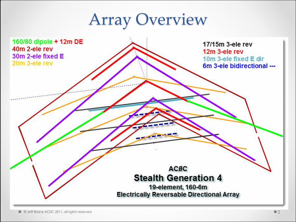
Array Overview
© Jeff Blaine AC0C 2011, all rights reserved 2
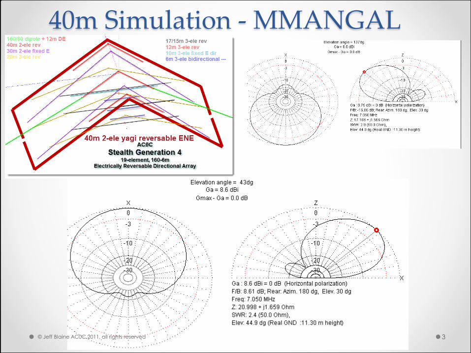
40m Simulation - MMANGAL
© Jeff Blaine AC0C 2011, all rights reserved 3
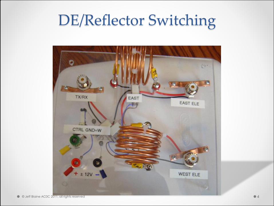
DE/Reflector Switching
© Jeff Blaine AC0C 2011, all rights reserved 4
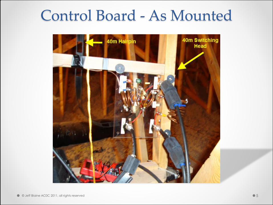
Control Board - As Mounted
© Jeff Blaine AC0C 2011, all rights reserved 5
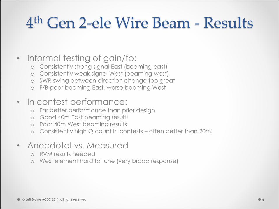
4th Gen 2-ele Wire Beam - Results
• Informal testing of gain/fb: o Consistently strong signal East (beaming east)
o Consistently weak signal West (beaming west)
o SWR swing between direction change too great
o F/B poor beaming East, worse beaming West
• In contest performance: o Far better performance than prior design
o Good 40m East beaming results
o Poor 40m West beaming results
o Consistently high Q count in contests – often better than 20m!
• Anecdotal vs. Measured o RVM results needed
o West element hard to tune (very broad response)
© Jeff Blaine AC0C 2011, all rights reserved 6
Measuring the Baseline
• 40m Beam - Parasitic to Phased Conversion
© Jeff Blaine AC0C 2011, all rights reserved 7
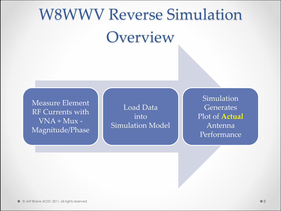
W8WWV Reverse Simulation
Overview
Measure Element RF Currents with
VNA + Mux - Magnitude/Phase
Load Data into
Simulation Model
Simulation Generates
Plot of Actual Antenna
Performance
© Jeff Blaine AC0C 2011, all rights reserved 8
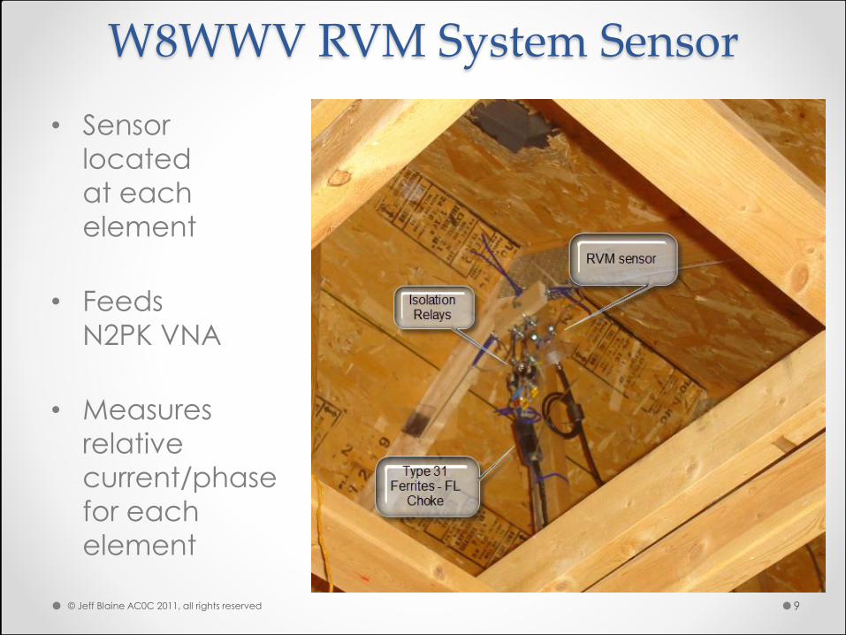
W8WWV RVM System Sensor
• Sensor
located
at each
element
• Feeds
N2PK VNA
• Measures
relative
current/phase
for each
element
© Jeff Blaine AC0C 2011, all rights reserved 9
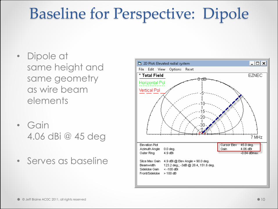
Baseline for Perspective: Dipole
• Dipole at
same height and
same geometry
as wire beam
elements
• Gain
4.06 dBi @ 45 deg
• Serves as baseline
© Jeff Blaine AC0C 2011, all rights reserved 10
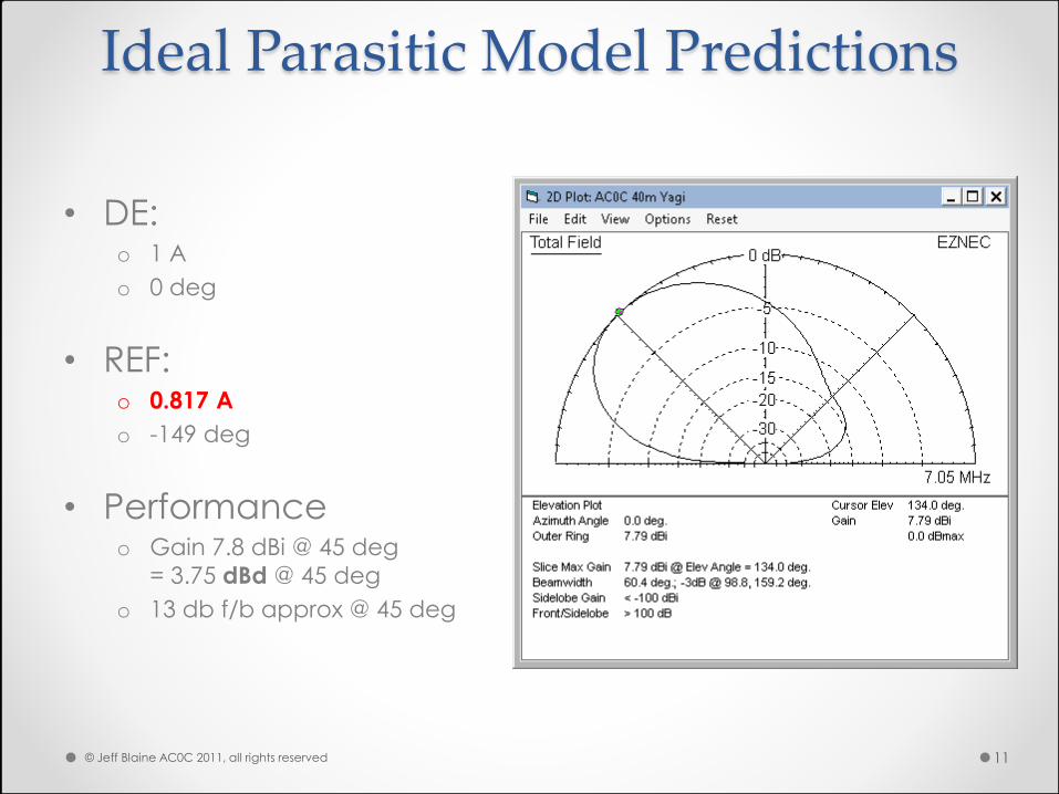
Ideal Parasitic Model Predictions
• DE: o 1 A
o 0 deg
• REF: o 0.817 A
o -149 deg
• Performance o Gain 7.8 dBi @ 45 deg
= 3.75 dBd @ 45 deg
o 13 db f/b approx @ 45 deg
© Jeff Blaine AC0C 2011, all rights reserved 11
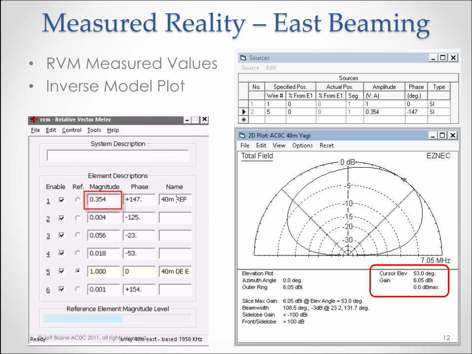
Measured Reality – East Beaming
• RVM Measured Values
• Inverse Model Plot
© Jeff Blaine AC0C 2011, all rights reserved 12
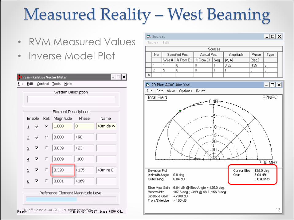
Measured Reality – West Beaming
• RVM Measured Values
• Inverse Model Plot
© Jeff Blaine AC0C 2011, all rights reserved 13
Measured Reality - Conclusions
• Actual vs. Ideal: o Gain 1.5 db less than ideal (EZ-NEC5)
o TOA ~10 degrees higher than ideal
o Good response to 90 degree signals more noise pickup
• Root cause of poor pattern: o Antenna trimmed for phase, current considered “given”
o But phase & current do interact – AND vary with frequency
o Best: lengths and spacing independently adjustable
• Complications: o Adjacent metal items unmodeled coupling and re-radiation effects
o The stucco factor?
• There must be a better way…
© Jeff Blaine AC0C 2011, all rights reserved 14
The NEW Plan
• Move west elements away from stucco wall
• Move models to EZ-NEC5 (easier help)
• Closer look at inadvertent parasitic interactions
• Use phased drive to force proper current/phase
• RVM system used to measure actual element
phase/currents
© Jeff Blaine AC0C 2011, all rights reserved 15
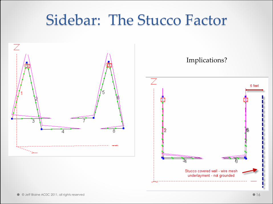
Sidebar: The Stucco Factor
Implications?
© Jeff Blaine AC0C 2011, all rights reserved 16
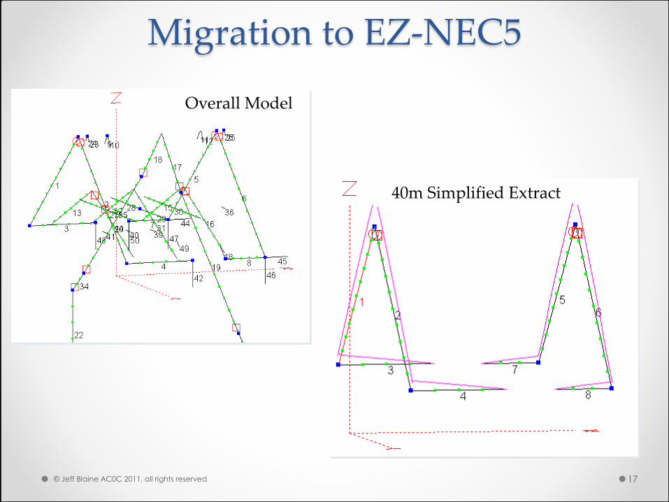
Migration to EZ-NEC5
40m Simplified Extract
Overall Model
© Jeff Blaine AC0C 2011, all rights reserved 17
Phased Drive Methodology
• 40m Beam - Parasitic to Phased Conversion
© Jeff Blaine AC0C 2011, all rights reserved 18
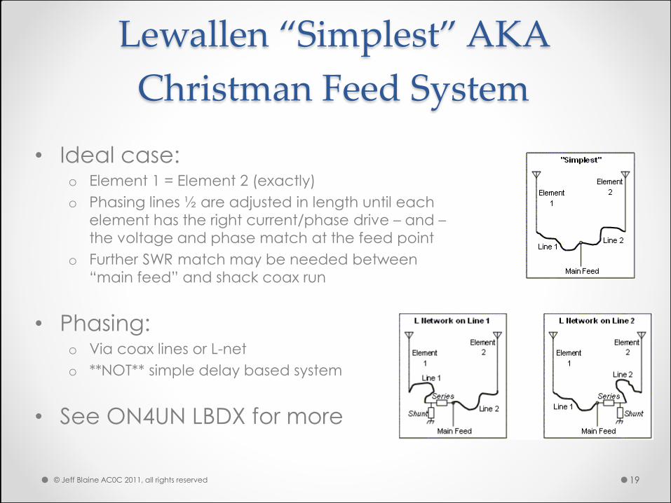
Lewallen “Simplest” AKA
Christman Feed System
• Ideal case: o Element 1 = Element 2 (exactly)
o Phasing lines ½ are adjusted in length until each
element has the right current/phase drive – and –
the voltage and phase match at the feed point
o Further SWR match may be needed between
“main feed” and shack coax run
• Phasing: o Via coax lines or L-net
o **NOT** simple delay based system
• See ON4UN LBDX for more
© Jeff Blaine AC0C 2011, all rights reserved 19
Christman Phasing – Key Steps
• Measure antenna (self and coupled Z) (VNA/MFJ)
• Calculate drive Z from measured data (ON4UN)
• Optional: Measure phase line values (VNA+ZPLOTS)
• Calculate phase line lengths (FEED2EL)
• Assembly & test
• Optional: SWR match to feed point
© Jeff Blaine AC0C 2011, all rights reserved 20
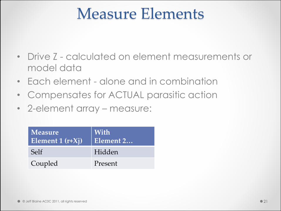
Measure Elements
Measure Element 1 (r+Xj)
With Element 2…
Self Hidden
Coupled Present
• Drive Z - calculated on element measurements or
model data
• Each element - alone and in combination
• Compensates for ACTUAL parasitic action
• 2-element array – measure:
© Jeff Blaine AC0C 2011, all rights reserved 21
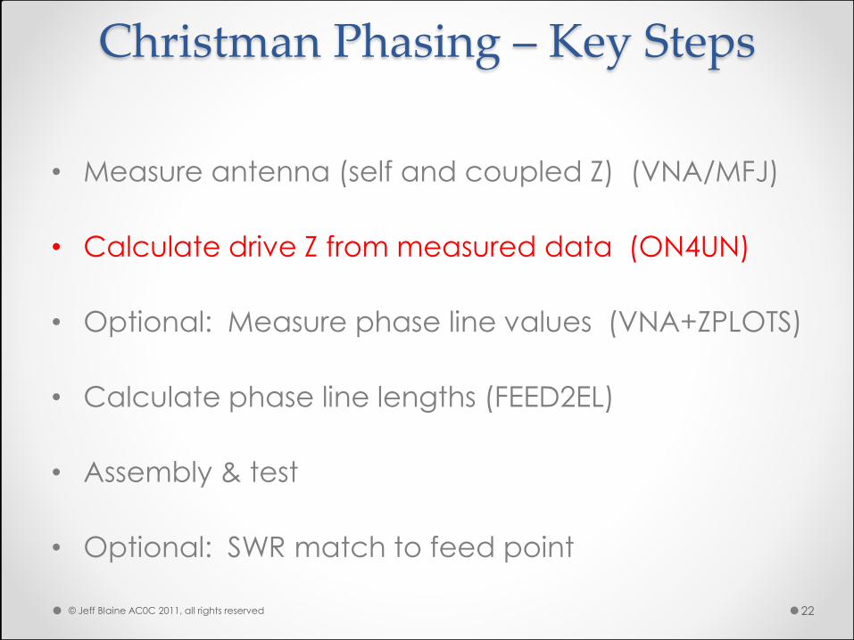
Christman Phasing – Key Steps
• Measure antenna (self and coupled Z) (VNA/MFJ)
• Calculate drive Z from measured data (ON4UN)
• Optional: Measure phase line values (VNA+ZPLOTS)
• Calculate phase line lengths (FEED2EL)
• Assembly & test
• Optional: SWR match to feed point
© Jeff Blaine AC0C 2011, all rights reserved 22
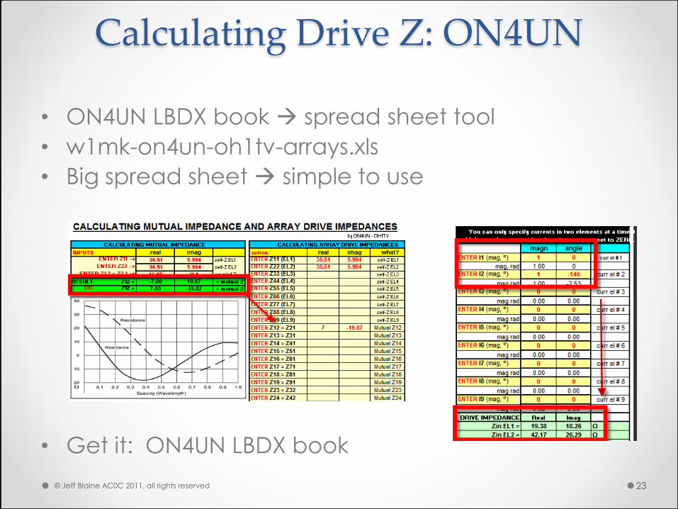
Calculating Drive Z: ON4UN
• ON4UN LBDX book spread sheet tool
• w1mk-on4un-oh1tv-arrays.xls
• Big spread sheet simple to use
• Get it: ON4UN LBDX book
© Jeff Blaine AC0C 2011, all rights reserved 23
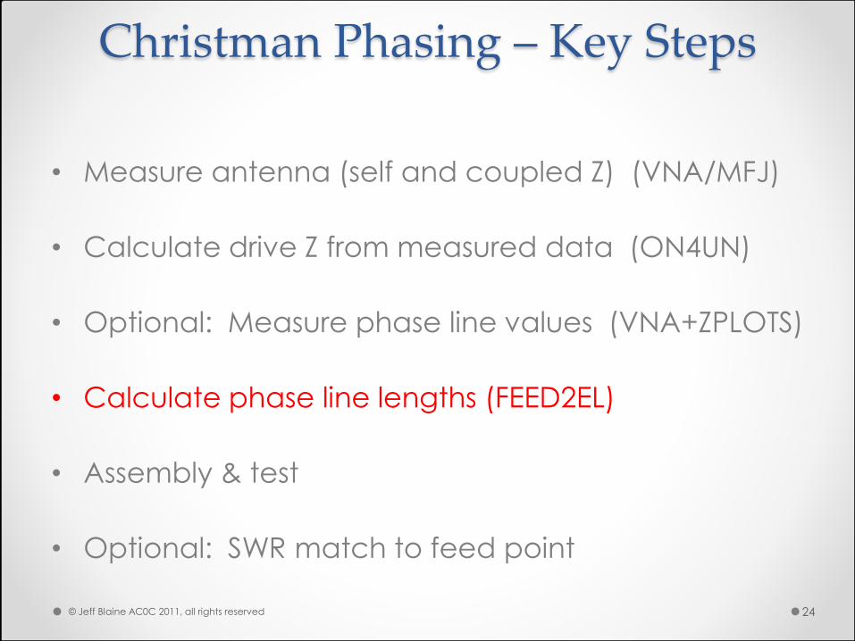
Christman Phasing – Key Steps
• Measure antenna (self and coupled Z) (VNA/MFJ)
• Calculate drive Z from measured data (ON4UN)
• Optional: Measure phase line values (VNA+ZPLOTS)
• Calculate phase line lengths (FEED2EL)
• Assembly & test
• Optional: SWR match to feed point
© Jeff Blaine AC0C 2011, all rights reserved 24
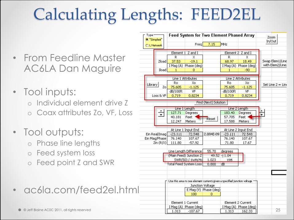
Calculating Lengths: FEED2EL
• From Feedline Master AC6LA Dan Maguire
• Tool inputs: o Individual element drive Z
o Coax attributes Zo, VF, Loss
• Tool outputs: o Phase line lengths
o Feed system loss
o Feed point Z and SWR
• ac6la.com/feed2el.html
© Jeff Blaine AC0C 2011, all rights reserved 25
Construction Details
• 40m Beam - Parasitic to Phased Conversion
© Jeff Blaine AC0C 2011, all rights reserved 26
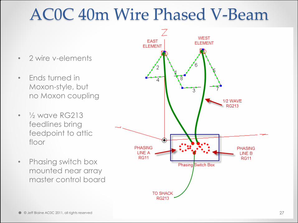
AC0C 40m Wire Phased V-Beam
• 2 wire v-elements
• Ends turned in
Moxon-style, but
no Moxon coupling
• ½ wave RG213
feedlines bring
feedpoint to attic
floor
• Phasing switch box
mounted near array
master control board
© Jeff Blaine AC0C 2011, all rights reserved 27
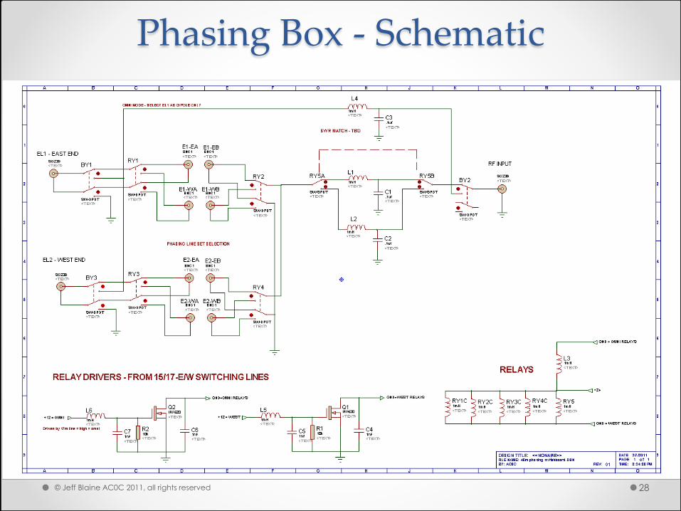
Phasing Box - Schematic
© Jeff Blaine AC0C 2011, all rights reserved 28
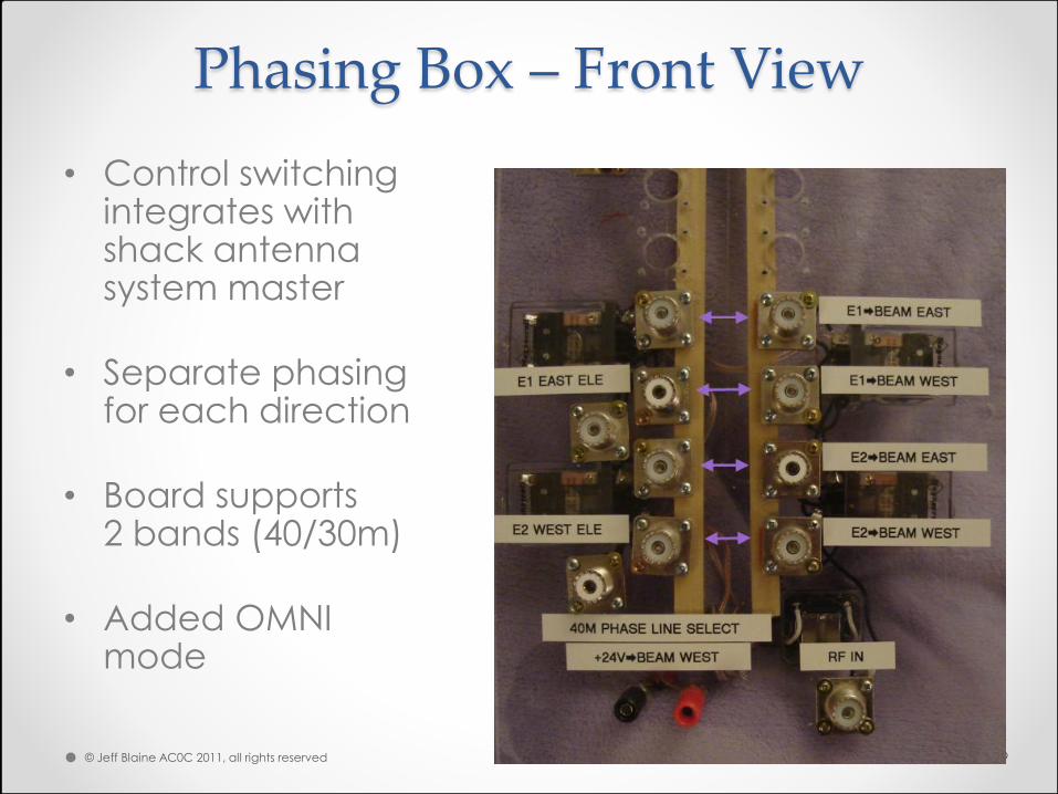
Phasing Box – Front View
• Control switching integrates with shack antenna system master
• Separate phasing for each direction
• Board supports 2 bands (40/30m)
• Added OMNI mode
© Jeff Blaine AC0C 2011, all rights reserved 29
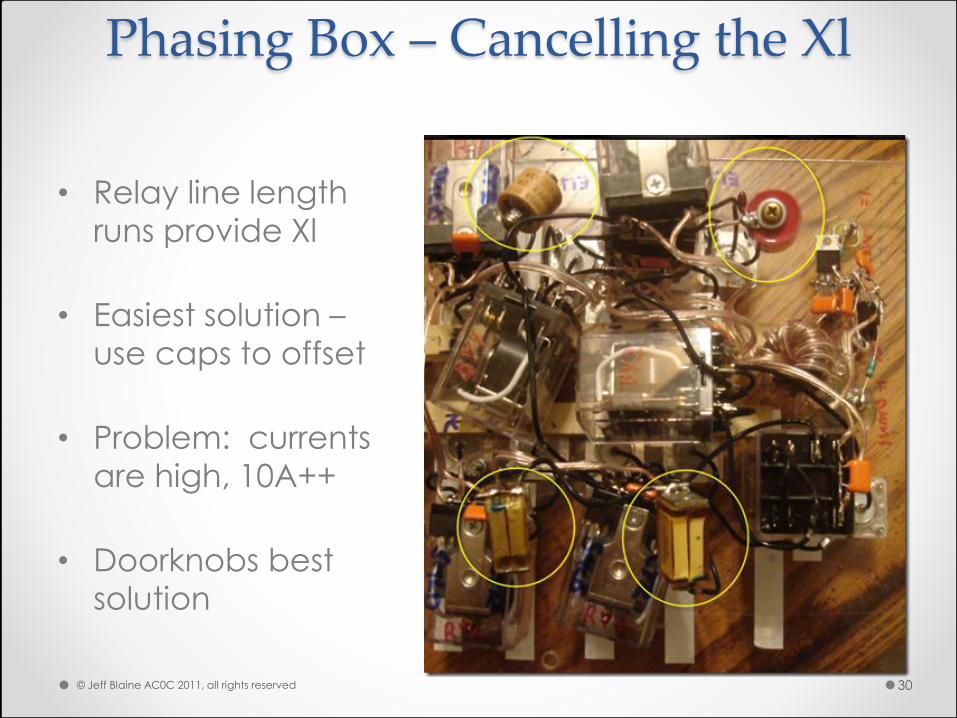
Phasing Box – Cancelling the Xl
• Relay line length
runs provide Xl
• Easiest solution –
use caps to offset
• Problem: currents
are high, 10A++
• Doorknobs best
solution
© Jeff Blaine AC0C 2011, all rights reserved 30
Results
• 40m Beam - Parasitic to Phased Conversion
© Jeff Blaine AC0C 2011, all rights reserved 31
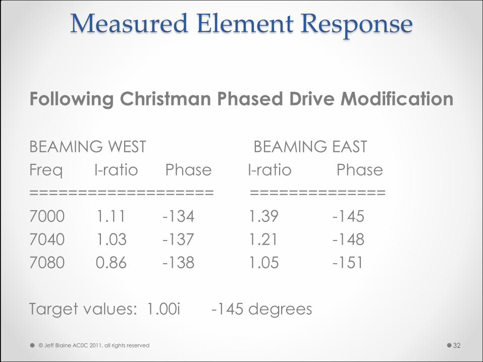
Measured Element Response
Following Christman Phased Drive Modification
BEAMING WEST BEAMING EAST
Freq I-ratio Phase I-ratio Phase
=================== ==============
7000 1.11 -134 1.39 -145
7040 1.03 -137 1.21 -148
7080 0.86 -138 1.05 -151
Target values: 1.00i -145 degrees
© Jeff Blaine AC0C 2011, all rights reserved 32
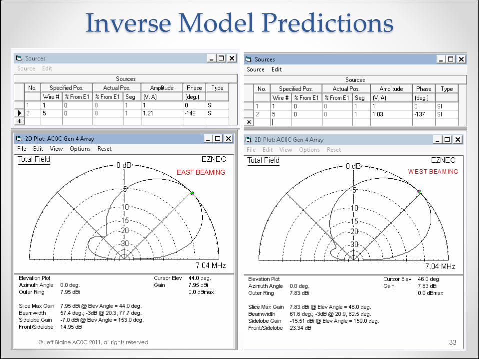
Inverse Model Predictions
© Jeff Blaine AC0C 2011, all rights reserved 33
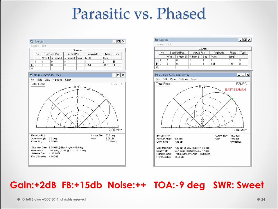
Parasitic vs. Phased
Gain:+2dB FB:+15db Noise:++ TOA:-9 deg SWR: Sweet
© Jeff Blaine AC0C 2011, all rights reserved 34
Conclusions
• Phased drive benefits: o Predictable current/phase
o Accommodates variations in mutual coupling
o Minimal trimming after assembly
o Delivers improved gain, F/B in real-world environments
• Phased drive problems: o Build complexity greater
o More similar elements are simpler to make bidirectional
o Antenna changes redo phasing lines
© Jeff Blaine AC0C 2011, all rights reserved 35
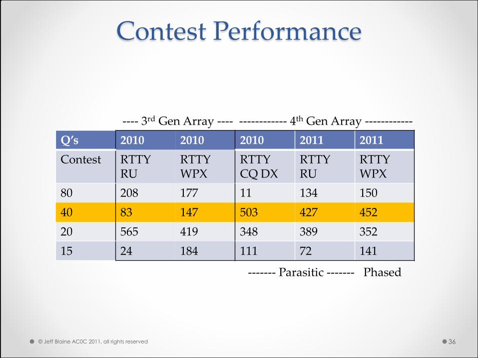
Contest Performance
Q’s 2010 2010 2010 2011 2011
Contest RTTY RU
RTTY WPX
RTTY CQ DX
RTTY RU
RTTY WPX
80 208 177 11 134 150
40 83 147 503 427 452
20 565 419 348 389 352
15 24 184 111 72 141
---- 3rd Gen Array ---- ------------ 4th Gen Array ------------
© Jeff Blaine AC0C 2011, all rights reserved 36
------- Parasitic ------- Phased

Special Thanks To:
• For Elmering a “phasing novice,” and cooking up
excellent tools for the ham world’s benefit… o Greg Ordy, W8WWV EZDZ, RVM
o Dan Mcguire, AC6LA FEED2EL, ZPLOTS
• For materials contributed o Jack Holzer, KD0MDA
o Rob Underwood, K0RU
o Jerry Chamberlin, WA0JRJ
o Dewey “Lucky” Jones, W0DRJ
© Jeff Blaine AC0C 2011, all rights reserved 37