Embed Size (px)
Citation preview
1 CO (SPDT) 2 CO (DPDT) 1 CO (SPDT)
12/25 8/15 16/30
250/400 250/400 250/400
3,000 2,000 4,000
600 400 750
0.5 0.3 0.5
12/0.3/0.12 8/0.3/0.12 16/0.3/0.12
300 (5/5) 300 (5/5) 300 (5/5)
AgNi AgNi AgNi
24 - 230 24 - 230 24 - 230
5 - 6 - 12 - 24 - 48 - 60 - 110 5 - 6 - 12 - 24 - 48 - 60 - 110 5 - 6 - 12 - 24 - 48 - 60 - 110
0.9/0.4 0.9/0.4 0.9/0.4
(0.8...1.1)UN (0.8...1.1)UN (0.8...1.1)UN
(0.7...1.5)UN (0.7...1.5)UN (0.7...1.5)UN
0.8/0.4UN 0.8/0.4 UN 0.8/0.4 UN
0.2/0.1UN 0.2/0.1 UN 0.2/0.1 UN
5·106/10·106 5·106/10·106 5·106/10·106
60 · 103 60 · 103 50 · 103
5/4 5/4 5/4
6 (8 mm) 6 (8 mm) 6 (8 mm)
1,000 1,000 1,000
–40…+70 (AC); +85 (DC) –40…+70 (AC); +85 (DC) –40…+70 (AC); +85 (DC)
RT II RT II RT II
Contact specification
Contact configuration
Rated current/Maximum peak current A
Rated voltage/Maximum switching voltage V AC
Rated load AC1 VA
Rated load AC15 (230 V AC) VA
Single phase motor rating (230 V AC) kW
Breaking capacity DC1: 30/110/220 V A
Minimum switching load mW (V/mA)
Standard contact material
Coil specification
Nominal voltage (UN) V AC (50/60 Hz)
V DC
Rated power AC/DC VA (50 Hz)/W
Operating range AC
DC
Holding voltage AC/DC
Must drop-out voltage AC/DC
Technical data
Mechanical life AC/DC cycles
Electrical life at rated load AC1 cycles
Operate/release time ms
Insulation between coil and contacts (1.2/50 μs) kV
Dielectric strength between open contacts V AC
Ambient temperature range °C
Environmental protection
Approvals (according to type)
Copper side view Copper side view Copper side view
1
Features1 & 2 Pole - Low profile (15.7 mm height) 41.31 - 1 Pole 12 A (3.5 mm pin pitch)41.52 - 2 Pole 8 A (5 mm pin pitch)41.61 - 1 Pole 16 A (5 mm pin pitch)
PCB mount- direct or via PCB socket
35 mm rail mount - via screw and screwless sockets
• AC and DC coils• 8 mm, 6 kV (1.2/50 μs) isolation, coil-contacts• Cadmium Free contact materials• Flux proof: RT II standard, (RT III option)
• 3.5 mm contact pin pitch• 1 Pole 12 A• PCB direct or via socket
• 5 mm contact pin pitch• 2 Pole 8 A• PCB direct or via socket
• 5 mm contact pin pitch• 1 Pole 16 A• PCB direct or via socket
FOR UL RATINGS SEE: “General technical information” page V
41 Series - Low profile PCB relays 8 - 12 - 16 A
41.31 41.52 41.61
12.6
15.7
3.8
29
0.8
0.4
0.6
III-2
013,
ww
w.fi
nder
net.c
om
41SERIES
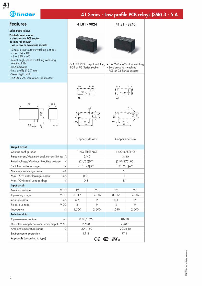
41.81 - 9024 41.81 - 8240
1 NO (SPST-NO) 1 NO (SPST-NO)
5/40 3/40
(24/35)DC (240/275)AC
(1.5...24)DC (12...240)AC
1 50
0.01 1
0.3 1.1
12 24 12 24
8...17 14...32 8...17 14...32
5.5 9 8.8 9
4 9 4 9
1,550 2,600 1,030 2,600
0.05/0.25 10/10
2,500 2,500
–20...+60 –20...+60
RT III RT III
Output circuit
Contact configuration
Rated current/Maximum peak current (10 ms) A
Rated voltage/Maximum blocking voltage V
Switching voltage range V
Minimum switching current mA
Max. “OFF-state” leakage current mA
Max. “ON-state” voltage drop V
Input circuit
Nominal voltage V DC
Operating range V DC
Control current mA
Release voltage V DC
Impedance Ω
Technical data
Operate/release time ms
Dielectric strength between input/output V AC
Ambient temperature range °C
Environmental protection
Approvals (according to type)
Copper side view Copper side view
FeaturesSolid State Relays
Printed circuit mount:- direct or via PCB socket 35 mm rail mount:- via screw or screwless sockets
• Single circuit output switching options- 5 A 24 V DC- 3 A 240 V AC
• Silent, high speed switching with longelectrical life
• LED indicator• Low profile (15.7 mm)• Wash tight: RT III• 2,500 V AC insulation, input-output
• 5 A, 24 V DC output switching• PCB or 93 Series sockets
• 3 A, 240 V AC output switching• Zero crossing switching• PCB or 93 Series sockets
41 Series - Low profile PCB relays (SSR) 3 - 5 A
2
III-2
013,
ww
w.fi
nder
net.c
om
41SERIES
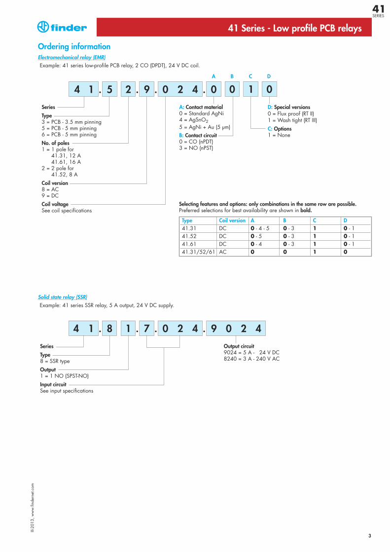
Example: 41 series low-profile PCB relay, 2 CO (DPDT), 24 V DC coil.
A: Contact material0 = Standard AgNi4 = AgSnO2 5 = AgNi + Au (5 μm)B: Contact circuit0 = CO (nPDT)3 = NO (nPST)
Series
Type3 = PCB - 3.5 mm pinning5 = PCB - 5 mm pinning6 = PCB - 5 mm pinning
No. of poles1 = 1 pole for
41.31, 12 A 41.61, 16 A
2 = 2 pole for41.52, 8 A
Coil version8 = AC9 = DC
Coil voltageSee coil specifications
D: Special versions0 = Flux proof (RT II)1 = Wash tight (RT III)
C: Options1 = None
A B C D
41 Series - Low profile PCB relays
Ordering information
5 2 09. . . .0 2 44 1 0 1 0
Type Coil version A B C D41.31 DC 0 - 4 - 5 0 - 3 1 0 - 141.52 DC 0 - 5 0 - 3 1 0 - 141.61 DC 0 - 4 0 - 3 1 0 - 141.31/52/61 AC 0 0 1 0
Selecting features and options: only combinations in the same row are possible.Preferred selections for best availability are shown in bold.
Example: 41 series SSR relay, 5 A output, 24 V DC supply.
Output circuit9024 = 5 A - 24 V DC8240 = 3 A - 240 V AC
Series
Type8 = SSR type
Output1 = 1 NO (SPST-NO)
Input circuitSee input specifications
8 1 7. . . .0 2 4 9 0 2 44 1
Solid state relay (SSR)
3
Electromechanical relay (EMR)
III-2
013,
ww
w.fi
nder
net.c
om
41SERIES
4
41 Series - Low profile PCB relays
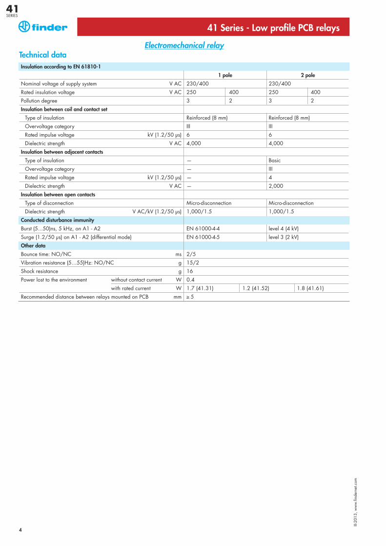
Technical dataInsulation according to EN 61810-1
1 pole 2 pole
Nominal voltage of supply system V AC 230/400 230/400
Rated insulation voltage V AC 250 400 250 400
Pollution degree 3 2 3 2
Insulation between coil and contact set
Type of insulation Reinforced (8 mm) Reinforced (8 mm)
Overvoltage category III III
Rated impulse voltage kV (1.2/50 μs) 6 6
Dielectric strength V AC 4,000 4,000
Insulation between adjacent contacts
Type of insulation — Basic
Overvoltage category — III
Rated impulse voltage kV (1.2/50 μs) — 4
Dielectric strength V AC — 2,000
Insulation between open contacts
Type of disconnection Micro-disconnection Micro-disconnection
Dielectric strength V AC/kV (1.2/50 μs) 1,000/1.5 1,000/1.5
Conducted disturbance immunity
Burst (5...50)ns, 5 kHz, on A1 - A2 EN 61000-4-4 level 4 (4 kV)
Surge (1.2/50 μs) on A1 - A2 (differential mode) EN 61000-4-5 level 3 (2 kV)
Other data
Bounce time: NO/NC ms 2/5
Vibration resistance (5…55)Hz: NO/NC g 15/2
Shock resistance g 16
Power lost to the environment without contact current W 0.4
with rated current W 1.7 (41.31) 1.2 (41.52) 1.8 (41.61)
Recommended distance between relays mounted on PCB mm ≥ 5
Electromechanical relay
III-2
013,
ww
w.fi
nder
net.c
om
41SERIES
5
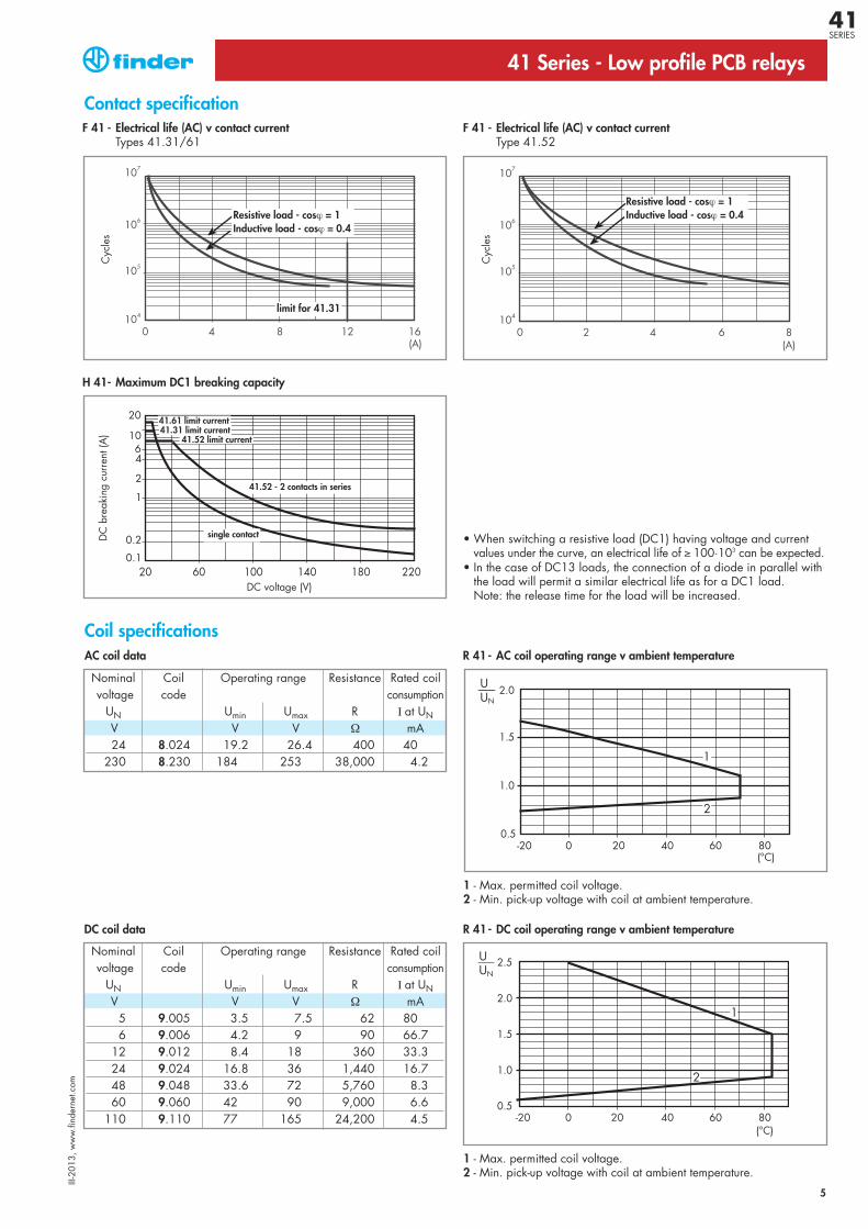
Coil specifications
Nominal Coil Operating range Resistance Rated coilvoltage code consumption
UN Umin Umax R I at UNV V V Ω mA
5 9.005 3.5 7.5 62 806 9.006 4.2 9 90 66.7
12 9.012 8.4 18 360 33.324 9.024 16.8 36 1,440 16.748 9.048 33.6 72 5,760 8.360 9.060 42 90 9,000 6.6
110 9.110 77 165 24,200 4.5
1 - Max. permitted coil voltage.2 - Min. pick-up voltage with coil at ambient temperature.
F 41 - Electrical life (AC) v contact currentTypes 41.31/61
Cyc
les
H 41- Maximum DC1 breaking capacity
41 Series - Low profile PCB relays
Contact specification
DC coil data
• When switching a resistive load (DC1) having voltage and current values under the curve, an electrical life of ≥ 100·103 can be expected.
• In the case of DC13 loads, the connection of a diode in parallel withthe load will permit a similar electrical life as for a DC1 load.Note: the release time for the load will be increased.
DC
bre
akin
g cu
rren
t (A
)
DC voltage (V)
R 41- DC coil operating range v ambient temperature
F 41 - Electrical life (AC) v contact currentType 41.52
Cyc
les
Resistive load - cosϕ = 1Inductive load - cosϕ = 0.4
limit for 41.31
Resistive load - cosϕ = 1Inductive load - cosϕ = 0.4
41.52 - 2 contacts in series
single contact
41.61 limit current41.31 limit current
41.52 limit current
Nominal Coil Operating range Resistance Rated coilvoltage code consumption
UN Umin Umax R I at UNV V V Ω mA24 8.024 19.2 26.4 400 40
230 8.230 184 253 38,000 4.2
1 - Max. permitted coil voltage.2 - Min. pick-up voltage with coil at ambient temperature.
AC coil data R 41- AC coil operating range v ambient temperature
III-2
013,
ww
w.fi
nder
net.c
om
41SERIES
41 Series - Low profile PCB relays
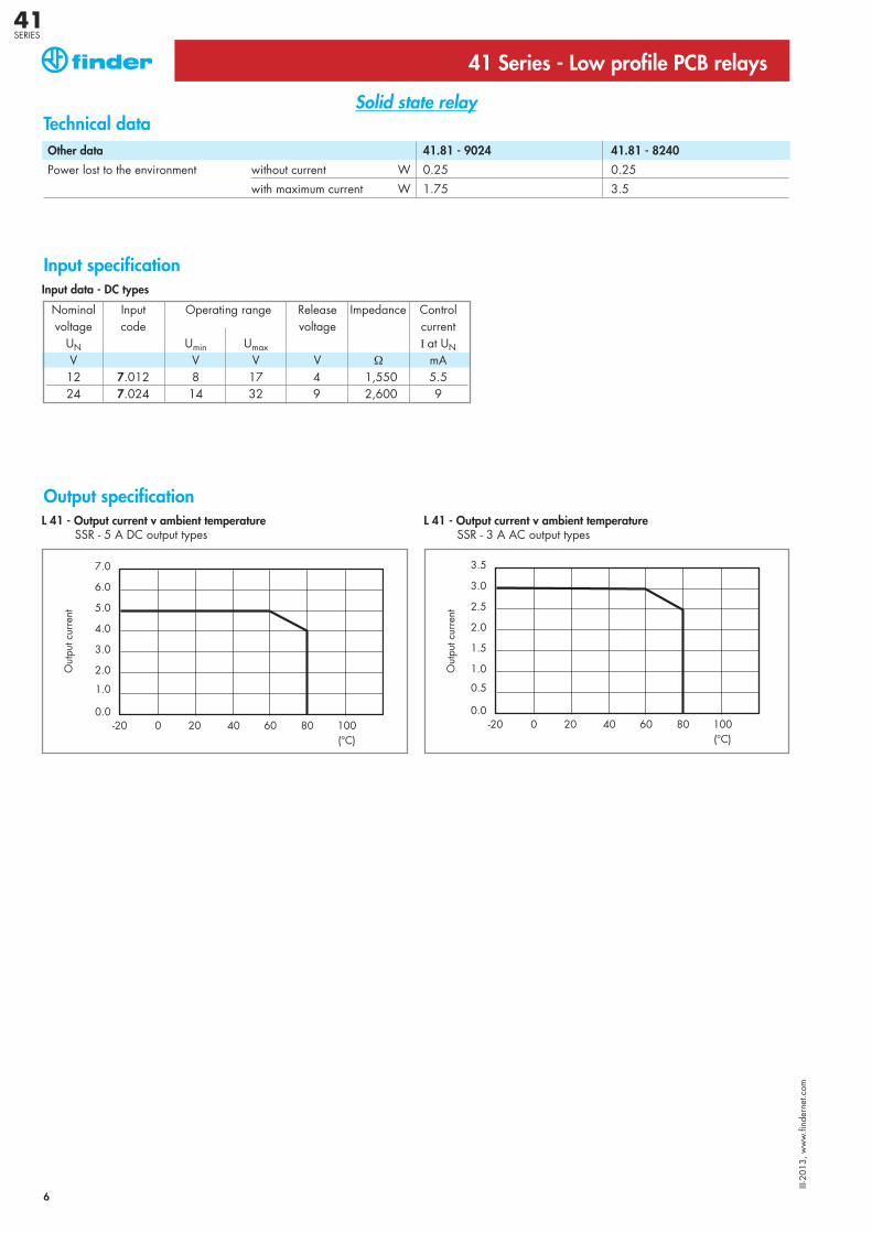
Solid state relayTechnical dataOther data 41.81 - 9024 41.81 - 8240
Power lost to the environment without current W 0.25 0.25
with maximum current W 1.75 3.5
Nominal Input Operating range Release Impedance Controlvoltage code voltage current
UN Umin Umax I at UNV V V V Ω mA12 7.012 8 17 4 1,550 5.524 7.024 14 32 9 2,600 9
Input data - DC types
Input specification
Output specification
Out
put c
urre
nt
Out
put c
urre
nt
L 41 - Output current v ambient temperatureSSR - 5 A DC output types
L 41 - Output current v ambient temperatureSSR - 3 A AC output types
6
III-2
013,
ww
w.fi
nder
net.c
om
41SERIES
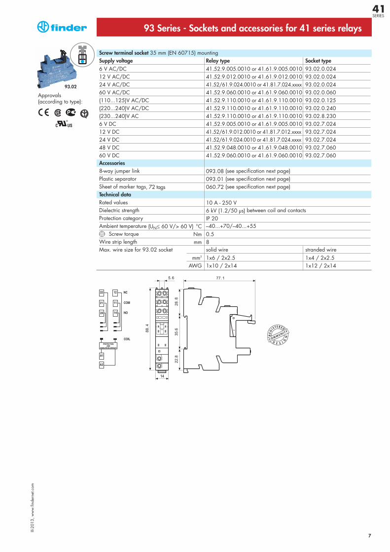
93.02
93 Series - Sockets and accessories for 41 series relays
Screw terminal socket 35 mm (EN 60715) mountingSupply voltage Relay type Socket type6 V AC/DC 41.52.9.005.0010 or 41.61.9.005.0010 93.02.0.02412 V AC/DC 41.52.9.012.0010 or 41.61.9.012.0010 93.02.0.02424 V AC/DC 41.52/61.9.024.0010 or 41.81.7.024.xxxx 93.02.0.02460 V AC/DC 41.52.9.060.0010 or 41.61.9.060.0010 93.02.0.060(110...125)V AC/DC 41.52.9.110.0010 or 41.61.9.110.0010 93.02.0.125(220...240)V AC/DC 41.52.9.110.0010 or 41.61.9.110.0010 93.02.0.240(230...240)V AC 41.52.9.110.0010 or 41.61.9.110.0010 93.02.8.2306 V DC 41.52.9.005.0010 or 41.61.9.005.0010 93.02.7.024 12 V DC 41.52/61.9.012.0010 or 41.81.7.012.xxxx 93.02.7.02424 V DC 41.52/61.9.024.0010 or 41.81.7.024.xxxx 93.02.7.02448 V DC 41.52.9.048.0010 or 41.61.9.048.0010 93.02.7.060 60 V DC 41.52.9.060.0010 or 41.61.9.060.0010 93.02.7.060 Accessories8-way jumper link 093.08 (see specification next page)Plastic separator 093.01 (see specification next page)Sheet of marker tags, 72 tags 060.72 (see specification next page)Technical dataRated values 10 A - 250 V Dielectric strength 6 kV (1.2/50 μs) between coil and contactsProtection category IP 20Ambient temperature (UN≤ 60 V/> 60 V) °C –40...+70/–40...+55
Screw torque Nm 0.5Wire strip length mm 8Max. wire size for 93.02 socket solid wire stranded wire
mm2 1x6 / 2x2.5 1x4 / 2x2.5AWG 1x10 / 2x14 1x12 / 2x14
Approvals (according to type):
7
III-2
013,
ww
w.fi
nder
net.c
om
41SERIES
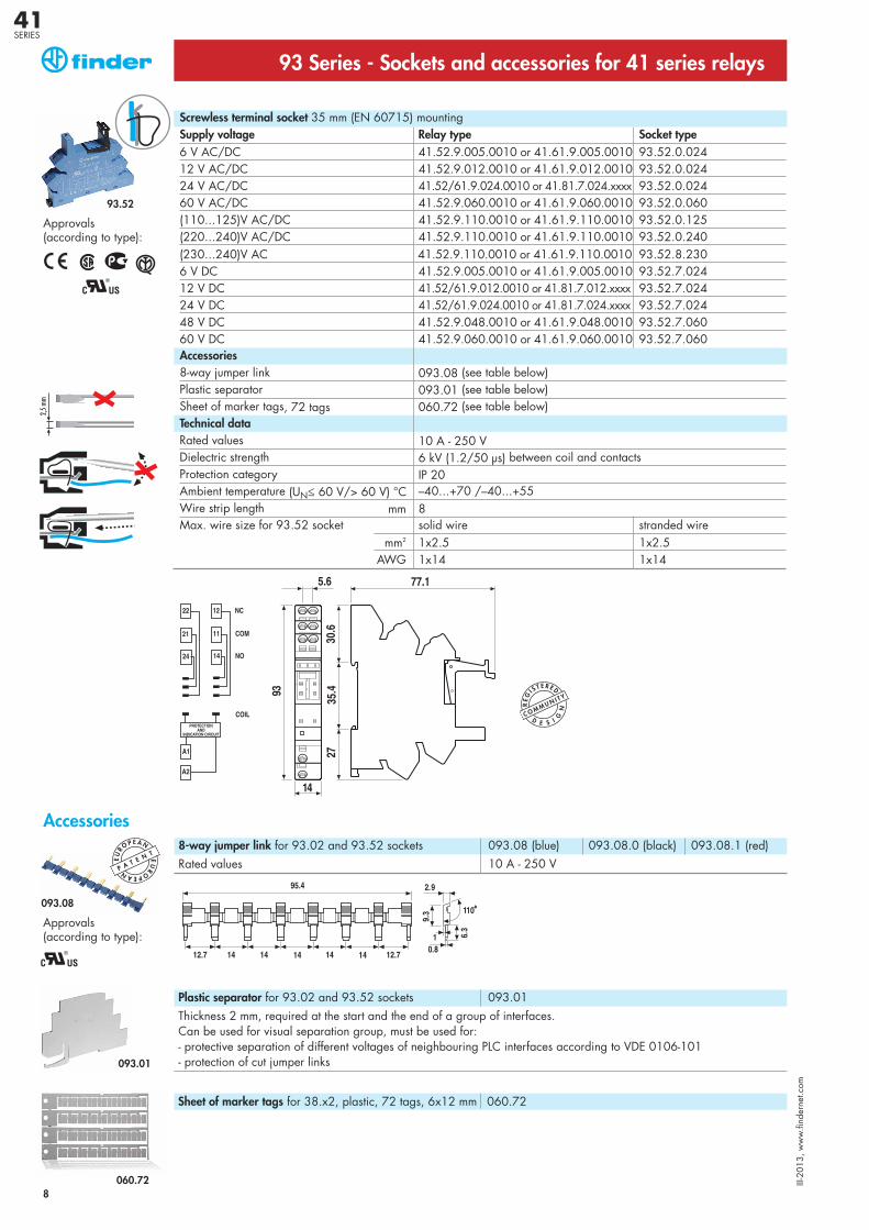
93.52
Screwless terminal socket 35 mm (EN 60715) mountingSupply voltage Relay type Socket type6 V AC/DC 41.52.9.005.0010 or 41.61.9.005.0010 93.52.0.02412 V AC/DC 41.52.9.012.0010 or 41.61.9.012.0010 93.52.0.02424 V AC/DC 41.52/61.9.024.0010 or 41.81.7.024.xxxx 93.52.0.02460 V AC/DC 41.52.9.060.0010 or 41.61.9.060.0010 93.52.0.060(110...125)V AC/DC 41.52.9.110.0010 or 41.61.9.110.0010 93.52.0.125(220...240)V AC/DC 41.52.9.110.0010 or 41.61.9.110.0010 93.52.0.240(230...240)V AC 41.52.9.110.0010 or 41.61.9.110.0010 93.52.8.2306 V DC 41.52.9.005.0010 or 41.61.9.005.0010 93.52.7.024 12 V DC 41.52/61.9.012.0010 or 41.81.7.012.xxxx 93.52.7.02424 V DC 41.52/61.9.024.0010 or 41.81.7.024.xxxx 93.52.7.02448 V DC 41.52.9.048.0010 or 41.61.9.048.0010 93.52.7.060 60 V DC 41.52.9.060.0010 or 41.61.9.060.0010 93.52.7.060Accessories8-way jumper link 093.08 (see table below)Plastic separator 093.01 (see table below)Sheet of marker tags, 72 tags 060.72 (see table below)Technical dataRated values 10 A - 250 V Dielectric strength 6 kV (1.2/50 μs) between coil and contactsProtection category IP 20Ambient temperature (UN≤ 60 V/> 60 V) °C –40...+70 /–40...+55Wire strip length mm 8Max. wire size for 93.52 socket solid wire stranded wire
mm2 1x2.5 1x2.5AWG 1x14 1x14
Approvals (according to type):
93 Series - Sockets and accessories for 41 series relays
Accessories
Approvals (according to type):
8-way jumper link for 93.02 and 93.52 sockets 093.08 (blue) 093.08.0 (black) 093.08.1 (red)Rated values 10 A - 250 V
Plastic separator for 93.02 and 93.52 sockets 093.01Thickness 2 mm, required at the start and the end of a group of interfaces.Can be used for visual separation group, must be used for:- protective separation of different voltages of neighbouring PLC interfaces according to VDE 0106-101- protection of cut jumper links
Sheet of marker tags for 38.x2, plastic, 72 tags, 6x12 mm 060.72
8
093.08
093.01
060.72
EU
ROPEAN E
URO P E A N
P A T E N T
III-2
013,
ww
w.fi
nder
net.c
om
41SERIES
2030
3.5
137.5
3.5
1.5
41.52 41.81 - 9024
41.81 - 8240
41.31
95.13.2 95.15.2
41.61
9
1 3.9 5 S L A
1 3.
2.
2.9 5
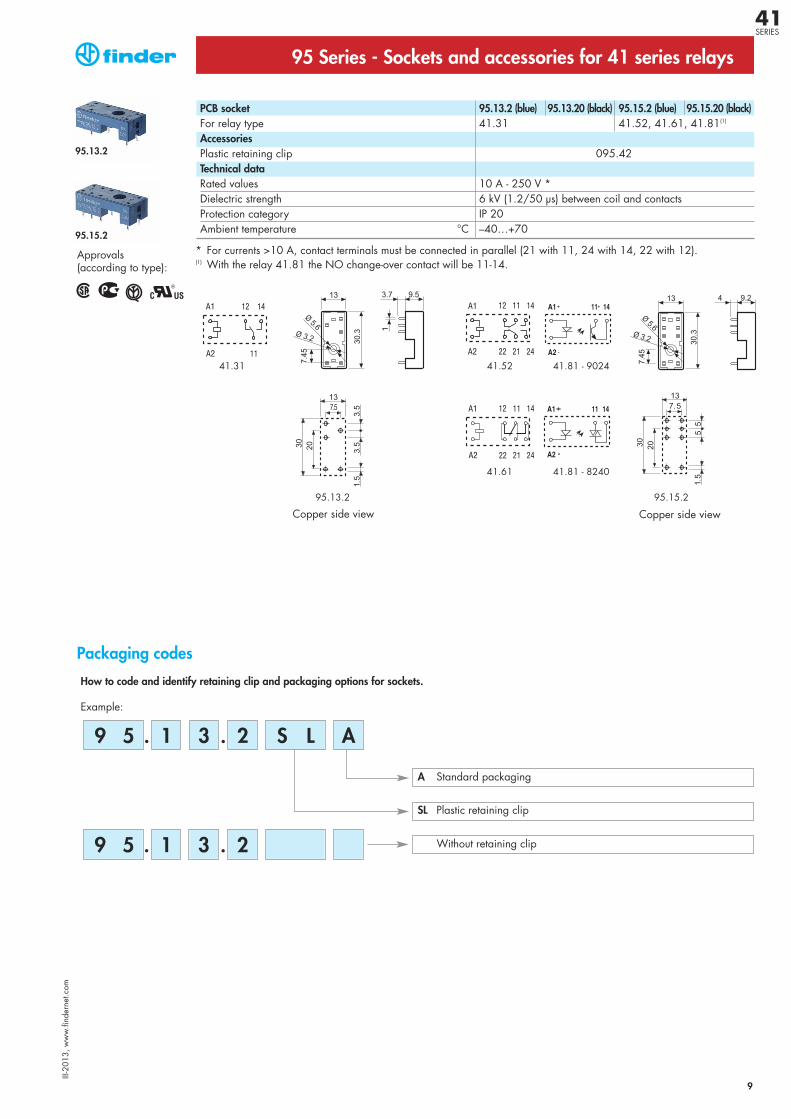
95 Series - Sockets and accessories for 41 series relays
How to code and identify retaining clip and packaging options for sockets.
Example:
Packaging codes
A Standard packaging
Without retaining clip
SL Plastic retaining clip
Approvals (according to type):
PCB socket 95.13.2 (blue) 95.13.20 (black) 95.15.2 (blue) 95.15.20 (black)For relay type 41.31 41.52, 41.61, 41.81(1)
AccessoriesPlastic retaining clip 095.42Technical dataRated values 10 A - 250 V *Dielectric strength 6 kV (1.2/50 μs) between coil and contactsProtection category IP 20Ambient temperature °C –40…+70
* For currents >10 A, contact terminals must be connected in parallel (21 with 11, 24 with 14, 22 with 12).(1) With the relay 41.81 the NO change-over contact will be 11-14.
Copper side viewCopper side view
95.15.2
95.13.2
III-2
013,
ww
w.fi
nder
net.c
om
41SERIES