Embed Size (px)
Citation preview
4.10 Geological models
127
4.10 Geological models
A geological model is a spatial representation of the distribution of sediments and rocks in the subsurface. The model is traditionally presented by 2D cross-sections, but increasingly visualised as digital 3D models (Artimo et al. 2003, Kassenaar et al. 2003, Hinsby & Abatzis 2004). The distribution of sediments controls the groundwater flow, and the migration of e.g. pollutants or saltwater in the subsurface, due to the varying physical, chemical and microbiological properties of the different sediment types (de Vries 1997, Refsgaard & Trolborg 2001, Harrar et al. 2003, Hojberg & Refsgaard 2004). Hence the geological model is the core of any deterministic groundwater flow model, such as e.g. the national hydrological model of Denmark (Henriksen et al., 2003). Considerable uncertainties are associated with the model set-up and parameterisation, and all groundwater flow models, including the geological model, should therefore be validated for a specific application (Refsgaard & Henriksen 2004). Conventionally, the results of geological and geophysical data collection are presented in 2D geological maps, profiles and thematic maps. This is adequate only, if effects of the three dimensional structure of the underground are not important for the problem to be solved. Buried valleys, however, have a pronounced 3D structure, therefore a 3D framework (Barnett et al. 1998, Kassenaar et al. 2003) is well-suited for integrating the results of large scale surveys like those, which have been performed in the BurVal pilot areas (see Chap. 5). Digital 2 and 3D geological modelling including both geological and geophysical data is currently increasing in disciplines such as petroleum–, mining– and hydro-geology (e.g. Hinsby & Binzer 2001, Chambers & Brown 2003, Rasmussen 2004a,b, Apel 2006). Such a 3D-framework can vary from simple conceptual models which describe the rough 3D-geological set-up of an area up to very complex digital models, not only showing the distribution of geological layers but also taking into account rock properties and changes in time. Depending on the requirements of a project a wide range of commercially available digital tools for the purposes of geological 3D-modelling exist, which
can differ extremely concerning costs, performance and user-friendliness. The software should preferably fulfil several prerequisites: ■ the import of all types of different basic data
must be possible
■ have interfaces to common databases
■ the created geological body must have topologies (neighbourhood relationships)
■ it must be possible to change the geological body, (to introduce of new information)
■ it must be possible to combine models of different parts to an overall model
■ the program must document the alterations occurring during the development of the model
■ it must be possible to assign differently types of information as attributes to the geological body and the program must be able to calculate the variation of the attributes in the 3D space
■ the program must be able to produce two dimensional maps and profiles
■ the program must be able to produce 3D visualisations of an integrating nature
■ the program must have user friendly interfaces and export facilities to groundwater modelling software.
4.10.1 Procedure for the development of
a Geological 3D model
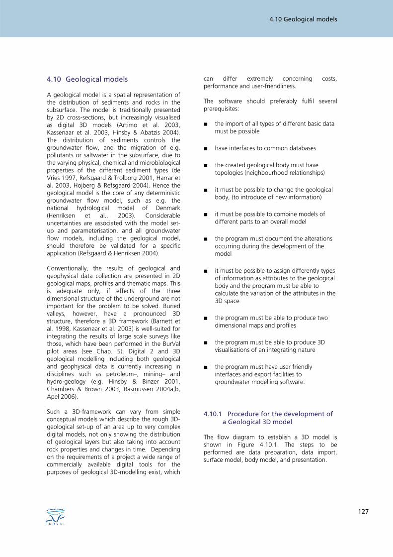
The flow diagram to establish a 3D model is shown in Figure 4.10.1. The steps to be performed are data preparation, data import, surface model, body model, and presentation.
JENS KRÖGER & KLAUS HINSBY
128
Fig. 4.10.1: Flow diagram showing the development of a 3D geological model.
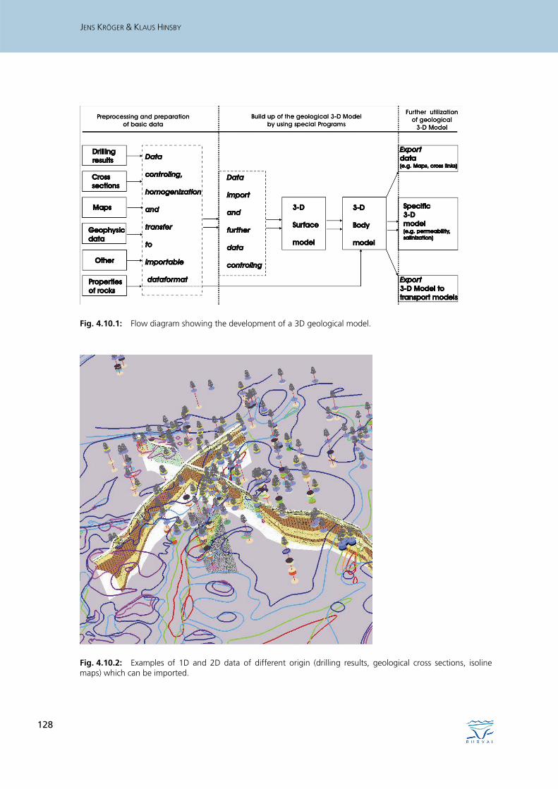
Fig. 4.10.2: Examples of 1D and 2D data of different origin (drilling results, geological cross sections, isoline maps) which can be imported.
4.10 Geological models
129
Data preparation
As a first step, the basic data must be checked and tested. Usually geological data have been collected over decades, and different experts were involved, so that data are based on different interpretations. All relevant data, e.g. maps, profiles, cross sections, geophysical and other data (Fig. 4.10.2), must be checked for consistency, and, if necessary and possible, they must be revised in order to produce a homogeneous data set. Usually, this needs a lot of manual work. Data import
The checked data from the various data sources, e.g. geological surveys, institutions, companies and various databases often have quite heterogenous formats. Hardly any software is able to import all these different data formats. Therefore all data have to be changed to a common proper format before being imported. Almost all known 3D programs allow a data import of at least the ASCII (American Standard Code for Information Interchange) format. First step in model generation: Surface models
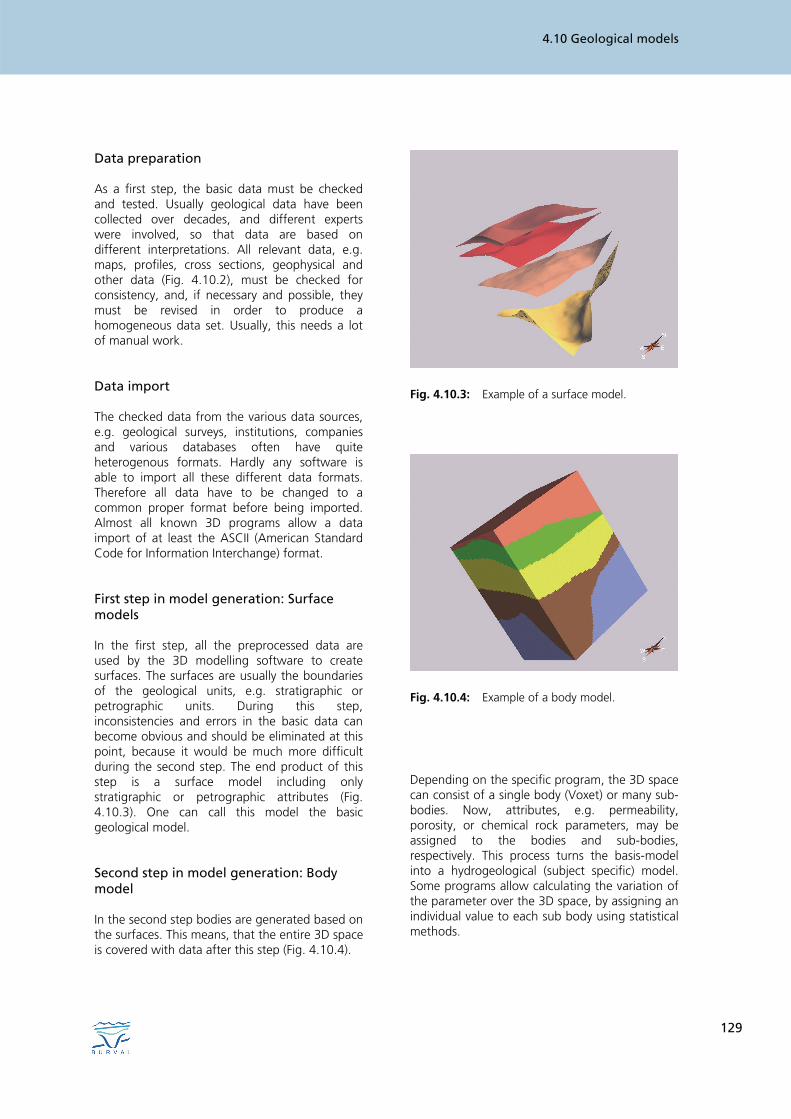
In the first step, all the preprocessed data are used by the 3D modelling software to create surfaces. The surfaces are usually the boundaries of the geological units, e.g. stratigraphic or petrographic units. During this step, inconsistencies and errors in the basic data can become obvious and should be eliminated at this point, because it would be much more difficult during the second step. The end product of this step is a surface model including only stratigraphic or petrographic attributes (Fig. 4.10.3). One can call this model the basic geological model. Second step in model generation: Body model
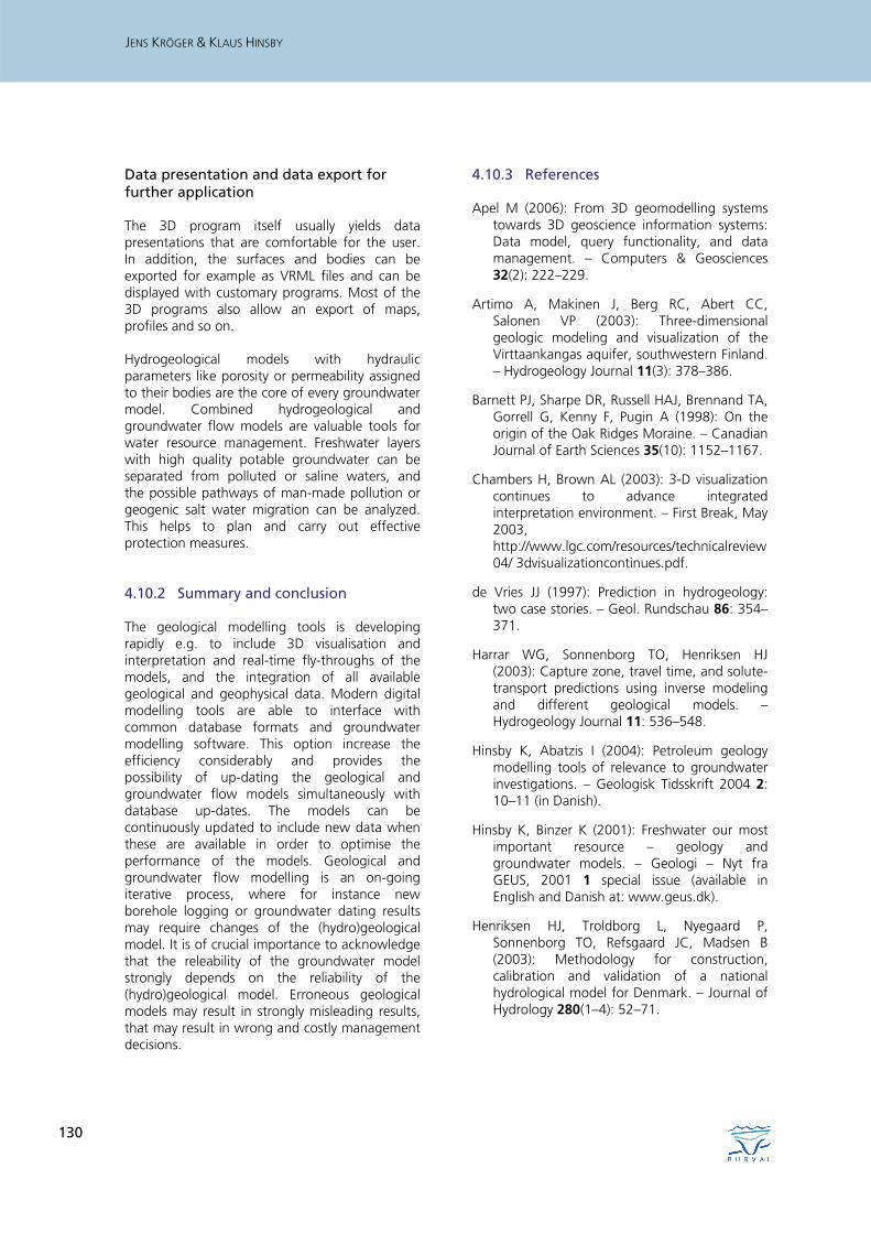
In the second step bodies are generated based on the surfaces. This means, that the entire 3D space is covered with data after this step (Fig. 4.10.4).
Fig. 4.10.3: Example of a surface model.
Fig. 4.10.4: Example of a body model.
Depending on the specific program, the 3D space can consist of a single body (Voxet) or many sub-bodies. Now, attributes, e.g. permeability, porosity, or chemical rock parameters, may be assigned to the bodies and sub-bodies, respectively. This process turns the basis-model into a hydrogeological (subject specific) model. Some programs allow calculating the variation of the parameter over the 3D space, by assigning an individual value to each sub body using statistical methods.
JENS KRÖGER & KLAUS HINSBY
130
Data presentation and data export for further application
The 3D program itself usually yields data presentations that are comfortable for the user. In addition, the surfaces and bodies can be exported for example as VRML files and can be displayed with customary programs. Most of the 3D programs also allow an export of maps, profiles and so on. Hydrogeological models with hydraulic parameters like porosity or permeability assigned to their bodies are the core of every groundwater model. Combined hydrogeological and groundwater flow models are valuable tools for water resource management. Freshwater layers with high quality potable groundwater can be separated from polluted or saline waters, and the possible pathways of man-made pollution or geogenic salt water migration can be analyzed. This helps to plan and carry out effective protection measures. 4.10.2 Summary and conclusion
The geological modelling tools is developing rapidly e.g. to include 3D visualisation and interpretation and real-time fly-throughs of the models, and the integration of all available geological and geophysical data. Modern digital modelling tools are able to interface with common database formats and groundwater modelling software. This option increase the efficiency considerably and provides the possibility of up-dating the geological and groundwater flow models simultaneously with database up-dates. The models can be continuously updated to include new data when these are available in order to optimise the performance of the models. Geological and groundwater flow modelling is an on-going iterative process, where for instance new borehole logging or groundwater dating results may require changes of the (hydro)geological model. It is of crucial importance to acknowledge that the releability of the groundwater model strongly depends on the reliability of the (hydro)geological model. Erroneous geological models may result in strongly misleading results, that may result in wrong and costly management decisions.
4.10.3 References
Apel M (2006): From 3D geomodelling systems towards 3D geoscience information systems: Data model, query functionality, and data management. – Computers & Geosciences 32(2): 222–229.
Artimo A, Makinen J, Berg RC, Abert CC, Salonen VP (2003): Three-dimensional geologic modeling and visualization of the Virttaankangas aquifer, southwestern Finland. – Hydrogeology Journal 11(3): 378–386.
Barnett PJ, Sharpe DR, Russell HAJ, Brennand TA, Gorrell G, Kenny F, Pugin A (1998): On the origin of the Oak Ridges Moraine. – Canadian Journal of Earth Sciences 35(10): 1152–1167.
Chambers H, Brown AL (2003): 3-D visualization continues to advance integrated interpretation environment. – First Break, May 2003, http://www.lgc.com/resources/technicalreview04/ 3dvisualizationcontinues.pdf.
de Vries JJ (1997): Prediction in hydrogeology: two case stories. – Geol. Rundschau 86: 354–371.
Harrar WG, Sonnenborg TO, Henriksen HJ (2003): Capture zone, travel time, and solute-transport predictions using inverse modeling and different geological models. – Hydrogeology Journal 11: 536–548.
Hinsby K, Abatzis I (2004): Petroleum geology modelling tools of relevance to groundwater investigations. – Geologisk Tidsskrift 2004 2: 10–11 (in Danish).
Hinsby K, Binzer K (2001): Freshwater our most important resource – geology and groundwater models. – Geologi – Nyt fra GEUS, 2001 1 special issue (available in English and Danish at: www.geus.dk).
Henriksen HJ, Troldborg L, Nyegaard P, Sonnenborg TO, Refsgaard JC, Madsen B (2003): Methodology for construction, calibration and validation of a national hydrological model for Denmark. – Journal of Hydrology 280(1–4): 52–71.
4.10 Geological models
131
Hojberg AL, Refsgaard JC (2005): Model uncertainty – parameter uncertainty versus conceptual models. – Water Science and Technology 52(6): 177–186.
Kassenaar D, Holysh S, Gerber R (2003): An integrated 3D Hydrostratigraphic Interpretation Methodology for Complex Aquifer Systems. – In: Poeter, Zheng, Hill and Doherty (eds.): Proceedings, MODFLOW and More, understanding through modelling, Colorado School of Mines, Golden CO, September 16–19, 2003, p. 661–665.
Rasmussen ES (2004a): The interplay between true eustatic sea-level changes, tectonics, and climatical changes: What is the dominating factor in sequence formation of the Upper Oligocene-Miocene succession in the eastern North Sea Basin, Denmark? – Global and Planetary Changes 41: 15–30.
Rasmussen ES (2004b): Stratigraphy and depositional evolution of the uppermost Oligocene – Miocene succession in Denmark. – Geological Society of Denmark, Bulletin 51: 89–109.
Refsgaard JC ,Henriksen HJ (2004): Modelling guidelines – terminology and guiding principles. – Advances in Water Resources 27(1): 71–82.
Refsgaard JC, Troldborg L (2001): Geological data improves groundwater models. In: Hinsby, K , Binzer, K (2001). Freshwater our most important resource – geology and groundwater models. – Geologi – Nyt fra GEUS, 2001, 1, special issue (available in English and Danish at: www.geus.dk).

JENS KRÖGER & KLAUS HINSBY
132