Embed Size (px)
Citation preview
657
4.11 Temperature Switches and Thermostats
B. G. LIPTÁK
(1982, 1995)
L. W. MOORE, B. ADLER
(2003)
Types:
A. Electronic SwitchesA1. Input From TransmitterA2. Input From Sensor in the Field
B. Electromechanical SwitchesC. Thermostats
C1. Electrical/ElectronicC2. Pneumatic
Range:
A1: Depends on sensor/transmitter rangeA2: Depends on sensor, from
−
328 to 4172
°
F (
−
200 to 2300
°
C)B: From 0 to 75
°
F (
−
8 to 24
°
C) up to 50 to 650
°
F (10 to 343
°
C) spans are standard;the maximum range is from
−
50 to 1100
°
F (
−
46 to 593
°
C)C: Room thermostat set points are adjustable from 45 to 85
°
F (7 to 29
°
C) for heatingand from 55 to 105
°
F (13 to 40
°
C) for cooling services
Cost:
A: $150 to $600B: Bimetallic spring elements cost only a few dollars; general purpose temperature
switches are $150; industrial-quality, indicating, explosion-proof temperatureswitches with thermowells cost $300 to $500
C: Conventional room thermostats cost from $50 to about $100; programmablemicroprocessor-based energy-saver thermostats cost $200 to $400
Inaccuracy:
B: 0.5 to 2% of spanC: Traditional thermostats are usually uncalibrated and their set point error can vary
from 0.5 to 3% and is not guaranteed. The microprocessor-based programmablethermostats are repeatable within 1
°
F (0.6
°
C).
Repeatability of Actuation:
A: 0.5% of span for analog, 0.05% for digital
Partial List of Suppliers:
Acromag (A1, A2) (www.acromag.com)Allen-Bradley (B) (www.ab.com)Ametek Drexelbrook (B) (www.drexelbrook.com)API (A1, A2) (www.api-usa.com)Applications Engineering Ltd. (B) (www.appeng.co.uk)ASCO (B) (www.ascovalve.com)Ashcroft (B) (www.dresserinstruments.com)Barksdale/Crane (B) (www.barksdale.com)Custom Control Sensors (B) (www.ccsduslsnap.com)Dallas Semiconductor/Maxim (B) (www.para.maxim-ic.com)Dresser Instruments (B) (www.dresserinstruments.com)Eurotherm/Action Instruments/Invensys (A1, A2) (www.actionio.com)Eurotherm/Barber Coleman (A1, A2, C) (www.eurotherm.com)Fluid Components (B) (www.fluidcomponents.com)Foxboro Co. (A1) (www.foxboro.com)Hi-Stat Div. Stoneridge (B) (www.histat.com/histat/temp-sw.htm)Honeywell (B) (www.thermalswitch.com)Honeywell (C) (www.content.honeywell.com/yourhome/ptc-thermostats/thermostat.ht)
Alarm
TSH
TT
Alarm
Flow Sheet Symbol
TS
Damper orValve
TC
© 2003 by Béla Lipták
658
Temperature Measurement
Honeywell Sensing and Control (A1, A2) (www.honeywell.com/sensing)Jumo (B) (www.jumoprocesscontrol.com)Kobold (B) (www.coboldusa.com)Mercoid/Dwyer (B) (www.dwyer-inst.com)Moore Industries-International, Inc. (A1, A2) (www.miinet.com)Neo-Dyn (B) (www.neodyn.com)Omega Engineering (A1, A2, B) (www.omega.com)Powers Controls (B, C) (www.powerscontrols.com)Robertshaw/Invensys (C) (www.robertshaw.com/cli-fam-robTherm.html)Rochester/Ametek (A1, A2) (www.rochester.com)Rosemount Inc. Div. of Emerson (A1) (www.rosemount.com)SOR (B) (www.sorinc.com/productsTemp.stm)Staefa/Siemens Building Automation (C) (www.sbt.siemens.com/hvp/Components/
catalog/thermostats.asp)Therm-O-Disc/Emerson (B) (www.thermodisc.com)Thermo Electric (B) (www.thermo-electric-direct.com)United Electric (B) (www.ueonline.com)White Rogers (C) (www.whiterogers.com)
INTRODUCTION
The terms
thermostat
and
temperature switch
are somewhatinterchangeable. Temperature switches are on-off devices,while thermostats are narrow (frequently fixed) proportionalband controllers. Their common characteristic is that mea-surement, set point, and control functions are all combinedinto a single instrument.
A thermostat is a device that controls the temperature inan enclosed space and can be electrical/electronic or pneu-matic. It functions either as a proportional-only controller oras an on-off switch with a dead-band.
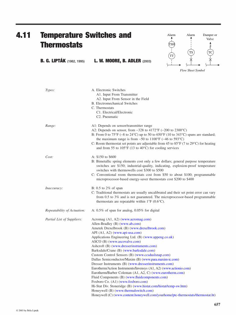
Figure 4.11a illustrates some of the terminology used inconnection with temperature switches. The temperature rangewithin which the actuation point can be set is referred to as
adjustable range.
The switch may actuate at its set point on
rising (
high
) or falling (
low
) temperature. The set point is thetemperature that actuates the switch to open or close anelectric circuit. The set point accuracy defines the band withinwhich repetitive actuations will occur. Differential or deadband is the difference between the set point and reactuationpoint. For example, if a high temperature switch is set toactuate (close) at 100
°
F (38
°
C) on rising temperature, it willclose at that point. When the temperature drops, it will notopen again until the temperature has fallen to 95
°
F (35
°
C).In this case, the differential is 5
°
F (2.8
°
C). Tolerance is therepeatable accuracy of the reactuation point.
Temperature switches utilize a wide variety of technolo-gies depending on their applications in commercial products,industrial equipment, process control, and even aerospace.They also vary in sophistication from simple snap disc mod-els typically used in coffee makers up through very sophis-ticated models. An alternate name for them is limit alarms.They can accept temperature sensor inputs from thermocou-ples (TCs) or resistance temperature detectors (RTDs) andprovide multiple alarms at different settings or serve bothalarm and equipment shutdown functions. This section willdiscuss both industrial and commercial switches as well aspersonal comfort (heating, ventilation, and air conditioning[HVAC]) thermostats.
ELECTRONIC TEMPERATURE SWITCHES
There are two types of electronic temperature switches (somesuppliers also call them limit alarms), which are differenti-ated by the source of their input signals. If the temperatureof interest is detected by a temperature transmitter, the highor low temperature switch detects a transmitter output signalof 4–20 mA or 1–5 V DC. If a transmitter is not available,a local process temperature sensor is connected directly tothe electronic high or low temperature switch (limit alarm),which is preferably mounted near the sensing point. Bothtypes will be discussed.
FIG. 4.11a
Temperature switch terminology.
High Temperature Switch(Detects Temperature Rise)
Low Temperature Switch(Detects Temperature Decrease)
Set Point
Set Point
Accuracy
Accuracy
Tolerance
Tolerance
ReactivationPoint
ReactivationPoint
Differential DifferentialAdjustable
Range
© 2003 by Béla Lipták
4.11 Temperature Switches and Thermostats
659
Input from Transmitter
Temperature transmitters with 4–20 mA output signals areoften connected to a programmable logic controller or dis-tributed control system for monitoring, alarming, and control.However, there are often requirements to have a backupdevice for monitoring the same signal for redundant alarmingand emergency equipment shutdown. It makes economicalsense to locate this device near the equipment being moni-tored so that shutdown commands need not be wired all theway from the control room.
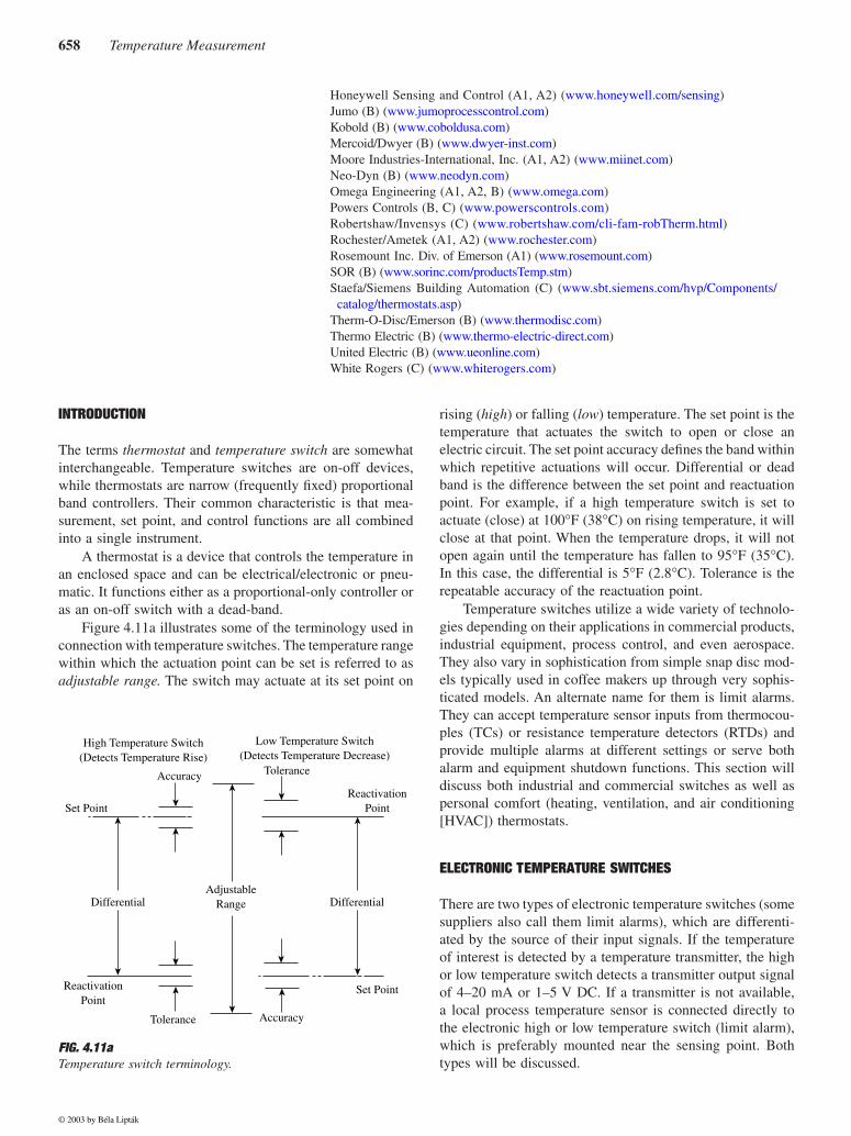
This type of temperature switch uses an analog circuitryand typically has either one or two trip points that are screw-driver adjusted and provide relay outputs. These analogswitches require a signal source and a continuity-measuringdevice to set the trip points. Such an analog temperatureswitch is shown in Figure 4.11b. Indicating models are alsoavailable, which indicate both the detected temperature andthe set point for switch actuation. Trip point repeatability asa percent of input span varies from 0.5 to 0.05% of span, asa function of whether the device is an inexpensive analogmodel or a more accurate digital one. Some models are alsoprovided with an adjustable dead band, which is a range,through which the input can change without causing a statechange in the switch position.
High-end digital temperature switches are field-configurablefor trip point, dead band, time delay, and latching options(Figure 4.11c). Others also incorporate an indicating display,which is scalable in various engineering units, or provideexcitation power for the temperature transmitter and retrans-mits the received input signal as an isolated 4–20 mA outputsignal. These temperature switches are available with 1 to 4relays.
Input Directly from Sensor
These direct connected temperature switches also range fromless sophisticated analog designs to the more sophisticatedfield-configurable digital models. For the analog switches,the type of sensor input must be specified while the digitalmodels can be field-configured for a variety of sensors. Thisincludes eight types of TCs and a number of RTDs, includingtwo-, three-, or four-wire circuitry and platinum, nickel, orcopper elements.
These switches also accept direct resistance input or mil-livolt signals. A valuable feature of these sensor input devicesis their ability to perform sensor diagnostics. One model pro-vides a relay output in the event of a sensor failure whileinhibiting the other alarm/shutdown outputs. The benefit isthat a nuisance shutdown of a piece of machinery or a processmay be avoided and yet the user knows that a sensor mustbe replaced to maintain monitoring.
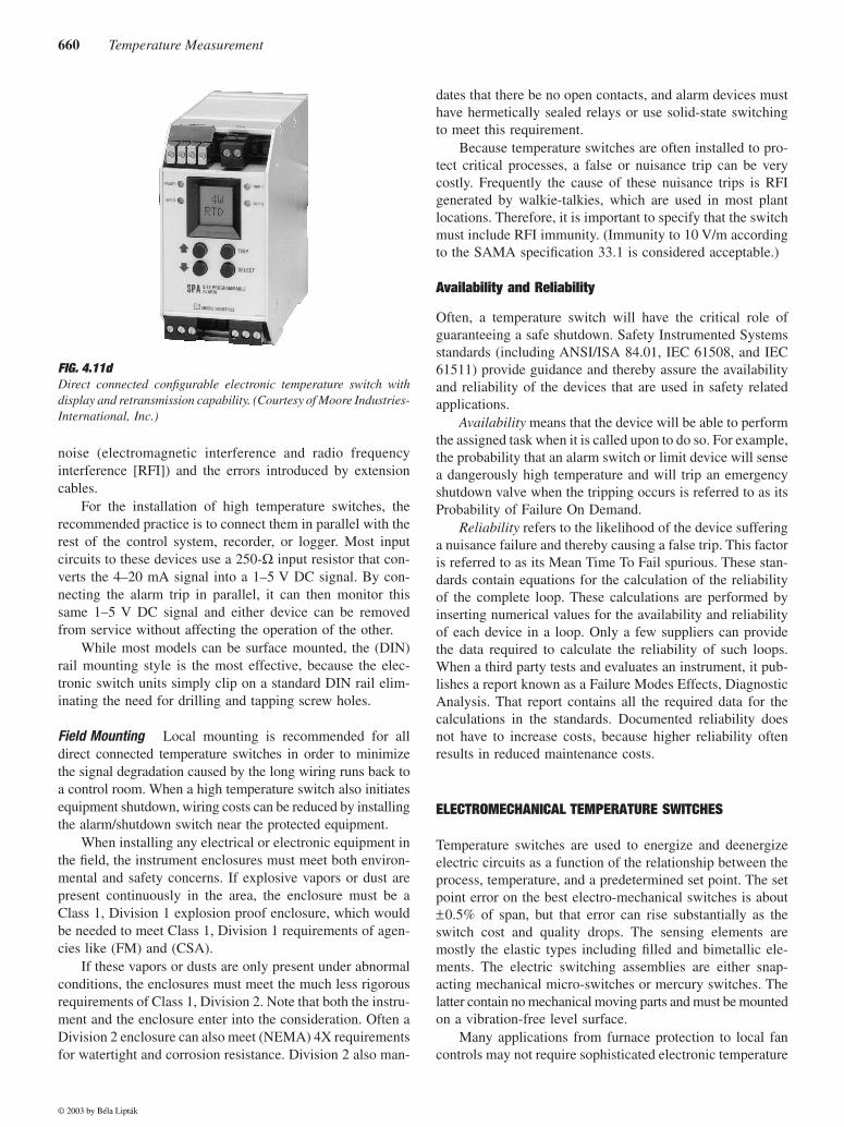
If the same temperature, which is detected by the tem-perature switch, is also needed for control, recording or otherreasons, some of these direct-connected devices are able toalso act as transmitters and output a 4–20 mA signal (Figure4.11d). This way, in addition to the temperature switch, thefunctions of indication and transmission are also provided bythe same unit.
Installation Considerations
In The Control Room
If a temperature transmitter output isalready being sent to the control room, it is logical to alsomount the temperature switch there. For direct sensor input,better performance is obtained by installing the instrumentclose to the sensor, in order to reduce the effects of electrical
FIG. 4.11b
Analog electronic switch operating off the output signal of a trans-mitter. (Courtesy of Moore Industries-International, Inc.)
FIG. 4.11c
Configurable and indicating digital electronic switch operating offthe output signal of a transmitter. (Courtesy of Moore Industries-International, Inc.)
© 2003 by Béla Lipták
660
Temperature Measurement
noise (electromagnetic interference and radio frequencyinterference [RFI]) and the errors introduced by extensioncables.
For the installation of high temperature switches, therecommended practice is to connect them in parallel with therest of the control system, recorder, or logger. Most inputcircuits to these devices use a 250-
Ω
input resistor that con-verts the 4–20 mA signal into a 1–5 V DC signal. By con-necting the alarm trip in parallel, it can then monitor thissame 1–5 V DC signal and either device can be removedfrom service without affecting the operation of the other.
While most models can be surface mounted, the (DIN)rail mounting style is the most effective, because the elec-tronic switch units simply clip on a standard DIN rail elim-inating the need for drilling and tapping screw holes.
Field Mounting
Local mounting is recommended for alldirect connected temperature switches in order to minimizethe signal degradation caused by the long wiring runs back toa control room. When a high temperature switch also initiatesequipment shutdown, wiring costs can be reduced by installingthe alarm/shutdown switch near the protected equipment.
When installing any electrical or electronic equipment inthe field, the instrument enclosures must meet both environ-mental and safety concerns. If explosive vapors or dust arepresent continuously in the area, the enclosure must be aClass 1, Division 1 explosion proof enclosure, which wouldbe needed to meet Class 1, Division 1 requirements of agen-cies like (FM) and (CSA).
If these vapors or dusts are only present under abnormalconditions, the enclosures must meet the much less rigorousrequirements of Class 1, Division 2. Note that both the instru-ment and the enclosure enter into the consideration. Often aDivision 2 enclosure can also meet (NEMA) 4X requirementsfor watertight and corrosion resistance. Division 2 also man-
dates that there be no open contacts, and alarm devices musthave hermetically sealed relays or use solid-state switchingto meet this requirement.
Because temperature switches are often installed to pro-tect critical processes, a false or nuisance trip can be verycostly. Frequently the cause of these nuisance trips is RFIgenerated by walkie-talkies, which are used in most plantlocations. Therefore, it is important to specify that the switchmust include RFI immunity. (Immunity to 10 V/m accordingto the SAMA specification 33.1 is considered acceptable.)
Availability and Reliability
Often, a temperature switch will have the critical role ofguaranteeing a safe shutdown. Safety Instrumented Systemsstandards (including ANSI/ISA 84.01, IEC 61508, and IEC61511) provide guidance and thereby assure the availabilityand reliability of the devices that are used in safety relatedapplications.
Availability
means that the device will be able to performthe assigned task when it is called upon to do so. For example,the probability that an alarm switch or limit device will sensea dangerously high temperature and will trip an emergencyshutdown valve when the tripping occurs is referred to as itsProbability of Failure On Demand.
Reliability
refers to the likelihood of the device sufferinga nuisance failure and thereby causing a false trip. This factoris referred to as its Mean Time To Fail spurious. These stan-dards contain equations for the calculation of the reliabilityof the complete loop. These calculations are performed byinserting numerical values for the availability and reliabilityof each device in a loop. Only a few suppliers can providethe data required to calculate the reliability of such loops.When a third party tests and evaluates an instrument, it pub-lishes a report known as a Failure Modes Effects, DiagnosticAnalysis. That report contains all the required data for thecalculations in the standards. Documented reliability doesnot have to increase costs, because higher reliability oftenresults in reduced maintenance costs.
ELECTROMECHANICAL TEMPERATURE SWITCHES
Temperature switches are used to energize and deenergizeelectric circuits as a function of the relationship between theprocess, temperature, and a predetermined set point. The setpoint error on the best electro-mechanical switches is about
±
0.5% of span, but that error can rise substantially as theswitch cost and quality drops. The sensing elements aremostly the elastic types including filled and bimetallic ele-ments. The electric switching assemblies are either snap-acting mechanical micro-switches or mercury switches. Thelatter contain no mechanical moving parts and must be mountedon a vibration-free level surface.
Many applications from furnace protection to local fancontrols may not require sophisticated electronic temperature
FIG. 4.11d
Direct connected configurable electronic temperature switch withdisplay and retransmission capability. (Courtesy of Moore Industries-International, Inc.)
© 2003 by Béla Lipták
4.11 Temperature Switches and Thermostats
661
switches, and in such applications bimetallic or filled bulbtype switches are used. The lower cost versions are providedonly with factory set fixed set points and fixed differentials,while the more expensive ones can be indicating and haveadjustable differentials and calibrated, externally adjustableset points and setting scales.
Features Required for Industrial Applications
Temperature switch elements should be selected with servicelife and maximum operating temperature in mind. Most elas-tic elements will have a service life of close to a millioncycles if the cycle time is not less than 5 s. The service lifeis related to the amount of current required to switch and thefrequency of switching. By increasing the dead-band, thefrequency of switching is reduced and the life of the switchincreases. Similarly, increasing the margin between the switchrating and the actual current flow handled will also increaseswitch life. For example, a device that is switching 4 A shouldhave a 10-A and not a 5-A rating.
Selection of the adjustable range for a specific installationshould consider both the set point actuation accuracy and thelife factor. For greatest accuracy, the set point should fall inthe upper half of the range, but for longest service life itshould be in the lower half. The usually acceptable compro-mise is to locate the set point in the middle third of the range.
It is desirable to have an external calibrated knob pro-vided on the temperature switch for set point adjustment.Uncalibrated or internal set point adjustments are generallyundesirable on industrial installations. The fixed differentialtemperature switches are furnished with a single adjustmentfor set point. These units are factory-set with differentialsthat range from 0.5 to 1% of span. On double-adjustment-type designs, both set points and reactuation points can beindependently adjusted. The maximum differential in suchdesigns is the range of the switch, while the minimum variesbetween 2 and 8% of span. Temperature switches with dualcontrol are also available. Here, two independent switchesmounted in the same housing are responding to the sameprocess temperature in opening or closing two independentcircuits.
Safety Considerations
The electrical rating of temperature switches at a 115 V oper-ating level varies from 0.3 to 10 A on AC or DC circuits.Generally, the dual control and the fixed differential switcheshave lower ratings, and the double-adjustment-type units havehigher ratings. The available circuit arrangements are veryflexible. Some of the standard arrangements include single-pole–single-throw, single-pole–double-throw, and double-pole–double-throw designs, but units are available with up tofour poles.
There are basically three standard case designs: generalpurpose (NEMA 1), weather-resistant (NEMA 2 and 3), andexplosion-proof (NEMA 7) cases. These enclosures and the
switches inside them may require certification to meet haz-ardous area classifications from certification agencies suchas FM, CSA, or Underwriters’ Laboratories.
In some designs, the control mechanism is an integral partof the explosion-proof case, while in others it can be removedin the field for maintenance. As noted earlier, the set pointshould be externally adjustable so that the explosion-proofcase does not need to be opened in order to change the setpoint. For added convenience of the operator, some switchesalso provide continuous process temperature indication.Another optional feature is push-button reset, which must bemanually operated before the circuit will be restored to itsoriginal state after an automatic operation. This manual resetencourages the operator to verify the safety of the systembefore restarting.
THERMOSTATS
Conventional thermostats are usually uncalibrated devicesand their manufacturers usually do not guarantee their accu-racy. This is a limitation, because it is possible to have somethermostats with as much as 5 to 10
°
F (3 to 6
°
C) error intheir measurement. In the last decades a new generation ofthermostats has been introduced that guarantee to limit theirerror to 1
°
F (0.6
°
C) or less.
Electromechanical Designs
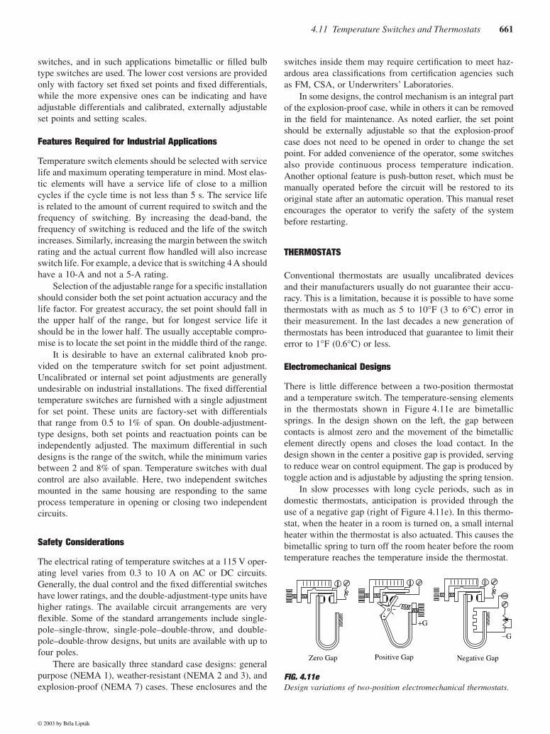
There is little difference between a two-position thermostatand a temperature switch. The temperature-sensing elementsin the thermostats shown in Figure 4.11e are bimetallicsprings. In the design shown on the left, the gap betweencontacts is almost zero and the movement of the bimetallicelement directly opens and closes the load contact. In thedesign shown in the center a positive gap is provided, servingto reduce wear on control equipment. The gap is produced bytoggle action and is adjustable by adjusting the spring tension.
In slow processes with long cycle periods, such as indomestic thermostats, anticipation is provided through theuse of a negative gap (right of Figure 4.11e). In this thermo-stat, when the heater in a room is turned on, a small internalheater within the thermostat is also actuated. This causes thebimetallic spring to turn off the room heater before the roomtemperature reaches the temperature inside the thermostat.
FIG. 4.11e
Design variations of two-position electromechanical thermostats.
Zero Gap Positive Gap Negative Gap
+G
−G
© 2003 by Béla Lipták
662
Temperature Measurement
Pneumatic Designs
Pneumatic-Bimetallic
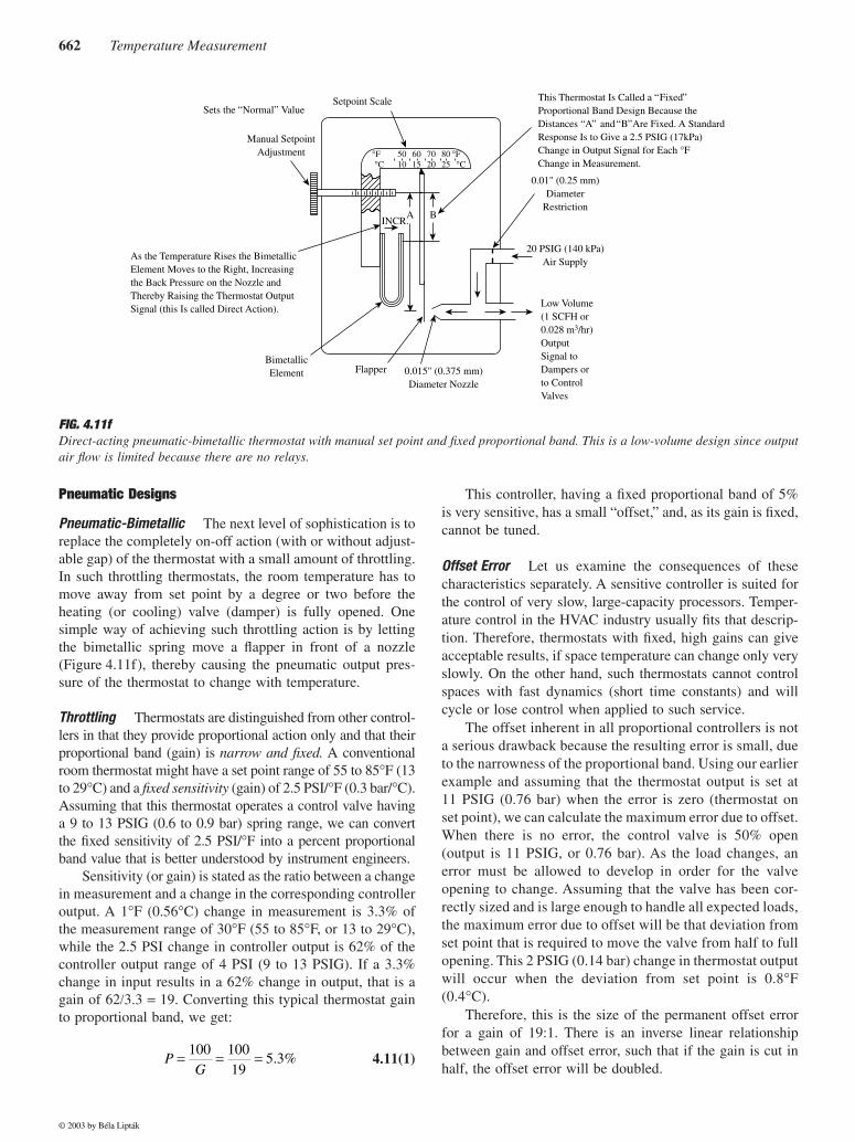
The next level of sophistication is toreplace the completely on-off action (with or without adjust-able gap) of the thermostat with a small amount of throttling.In such throttling thermostats, the room temperature has tomove away from set point by a degree or two before theheating (or cooling) valve (damper) is fully opened. Onesimple way of achieving such throttling action is by lettingthe bimetallic spring move a flapper in front of a nozzle(Figure 4.11f), thereby causing the pneumatic output pres-sure of the thermostat to change with temperature.
Throttling
Thermostats are distinguished from other control-lers in that they provide proportional action only and that theirproportional band (gain) is
narrow and fixed.
A conventionalroom thermostat might have a set point range of 55 to 85
°
F (13to 29
°
C) and a
fixed sensitivity
(gain) of 2.5 PSI/
°
F (0.3 bar/
°
C).Assuming that this thermostat operates a control valve havinga 9 to 13 PSIG (0.6 to 0.9 bar) spring range, we can convertthe fixed sensitivity of 2.5 PSI/
°
F into a percent proportionalband value that is better understood by instrument engineers.
Sensitivity (or gain) is stated as the ratio between a changein measurement and a change in the corresponding controlleroutput. A 1
°
F (0.56
°
C) change in measurement is 3.3% ofthe measurement range of 30
°
F (55 to 85
°
F, or 13 to 29
°
C),while the 2.5 PSI change in controller output is 62% of thecontroller output range of 4 PSI (9 to 13 PSIG). If a 3.3%change in input results in a 62% change in output, that is again of 62
/
3.3
=
19. Converting this typical thermostat gainto proportional band, we get:
4.11(1)
This controller, having a fixed proportional band of 5%is very sensitive, has a small “offset,” and, as its gain is fixed,cannot be tuned.
Offset Error
Let us examine the consequences of thesecharacteristics separately. A sensitive controller is suited forthe control of very slow, large-capacity processors. Temper-ature control in the HVAC industry usually fits that descrip-tion. Therefore, thermostats with fixed, high gains can giveacceptable results, if space temperature can change only veryslowly. On the other hand, such thermostats cannot controlspaces with fast dynamics (short time constants) and willcycle or lose control when applied to such service.
The offset inherent in all proportional controllers is nota serious drawback because the resulting error is small, dueto the narrowness of the proportional band. Using our earlierexample and assuming that the thermostat output is set at11 PSIG (0.76 bar) when the error is zero (thermostat onset point), we can calculate the maximum error due to offset.When there is no error, the control valve is 50% open(output is 11 PSIG, or 0.76 bar). As the load changes, anerror must be allowed to develop in order for the valveopening to change. Assuming that the valve has been cor-rectly sized and is large enough to handle all expected loads,the maximum error due to offset will be that deviation fromset point that is required to move the valve from half to fullopening. This 2 PSIG (0.14 bar) change in thermostat outputwill occur when the deviation from set point is 0.8
°
F(0.4
°
C).Therefore, this is the size of the permanent offset error
for a gain of 19:1. There is an inverse linear relationshipbetween gain and offset error, such that if the gain is cut inhalf, the offset error will be doubled.
FIG. 4.11f
Direct-acting pneumatic-bimetallic thermostat with manual set point and fixed proportional band. This is a low-volume design since outputair flow is limited because there are no relays.
This Thermostat Is Called a FixedProportional Band Design Because theDistances A and B Are Fixed. A StandardResponse Is to Give a 2.5 PSIG (17kPa)Change in Output Signal for Each °FChange in Measurement.
Setpoint Scale
50 60 70 80 °F10 15 20 25 °C
°F°C
Sets the Normal Value
Manual SetpointAdjustment
As the Temperature Rises the BimetallicElement Moves to the Right, Increasingthe Back Pressure on the Nozzle andThereby Raising the Thermostat OutputSignal (this Is called Direct Action).
BimetallicElement Flapper 0.015" (0.375 mm)
Diameter Nozzle
20 PSIG (140 kPa)Air Supply
0.01" (0.25 mm)Diameter
Restriction
Low Volume(1 SCFH or0.028 m3/hr)OutputSignal toDampers orto ControlValves
AINCR.
B
PG
= = =100 10019
5 3. %
© 2003 by Béla Lipták
4.11 Temperature Switches and Thermostats
663
From the above discussion it might be concluded that theconventional room thermostat is a good selection for theHVAC-type applications and that more expensive instru-ments, such as PID controllers, would not necessarilyimprove the overall performance.
Design Features
Application engineers can choose from afairly large variety of design features when specifying ther-mostats, because they cannot only be electromechanical,pneumatic, or electronic, but can also be (1) indicating orblind, (2) direct or reverse acting, (3) can automatically switchtheir actions in response to a pneumatic or electronic signal,(4) can have bimetallic, filled, or electronic sensing elements,(5) can have local or remote set points, or (6) have their setpoints under key, concealed, or externally adjustable.
Advanced Features
If the set point of a pneumatic thermo-stat is adjusted remotely by an air signal, each 1 PSIG (0.07 bar)change in set point pressure will move the set point by anadjustable preset amount. The range of this adjustment isusually from 0.15 to 1.4
°
F (0.1 to 0.8
°
C) per 1 PSI (0.07 bar).If the set point is to change as a function of the time of day,a timer can automatically operate a solenoid and therebyswitch the set point signal.
Some of the more recently developed and more advancedthermostat features include the following:
Adjustable Gains or Proportional Bands
Another term usedto describe the sensitivity of thermostats is throttling range.As shown in Figure 4.11g, it refers to the amount of temper-ature change that is required to change the thermostat outputfrom 3 to 13 PSIG (0.2 to 0.9 bar). The throttling range isusually adjustable from 2 to 10
°
F (1 to 5
°
C).
Dual Set Points
These thermostats will switch their settingsin response to a change in the air supply pressure. Both setpoints can be manually adjusted, with the day setting made byexternal thumbwheel and the night setting concealed internally.
Limited Control Range
These thermostats allow the occu-pant of an office to move the set point to any value desired,but will disregard any setting that exceeds the limit value.For example, in heating applications, the limit could be 74
°
F(23
°
C). In this case, the space temperature will be limited toa maximum of 74
°
F, regardless of the setting by the occupant.Similar limit values can be set for cooling.
Zero Energy Band Control
A recent addition to the avail-able thermostat choices is the zero energy band (ZEB) design.The idea behind ZEB control is to conserve energy by notusing any when the room is comfortable. As illustrated byFigure 4.11h, the conventional thermostat wastes energy bycontinuing to use energy when the area’s temperature isalready comfortable. The comfort gap, or ZEB, is adjustableand can be varied to match the nature of the particular spaceinvolved.
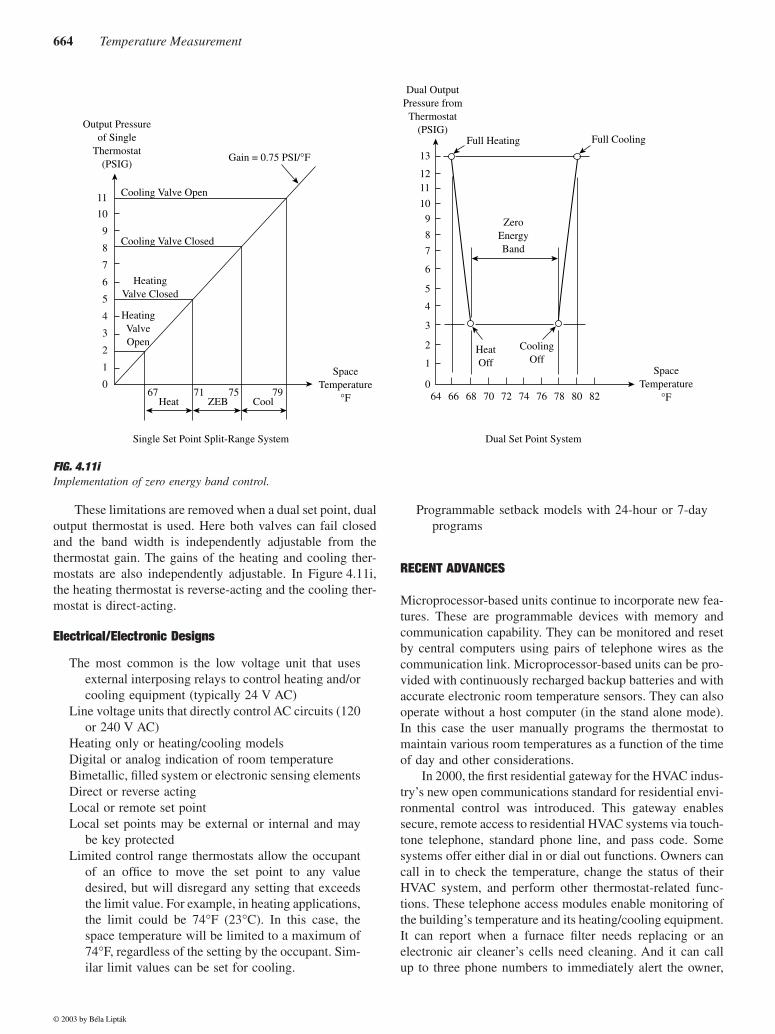
ZEB control can be accomplished in one of two ways. Thesingle set point and single output approach is illustrated on theleft side of Figure 4.11i. Here the cooling valve fails closedand is shown to have an 8 to 11 PSIG (0.55 to 0.76 bar) springrange, while the heating valve is selected to fail open and hasa 2 to 5 PSIG (0.14 to 0.34 bar) range. Therefore, between 5and 8 PSIG (0.34 and 0.55) both valves are closed, and no payenergy is expended while the thermostat output is within thisrange. The throttling range is usually adjustable from 5 to 25
°
F(3 to 13
°
C). Thus, if the ZEB is 30% of the throttling range,it can be varied from a gap size of 1.5
°
F (0.85
°
C) to 7.5
°
F(4.2
°
C) by changing the throttling range (or gain).
Split Range Control
While the split-range approach is a littleless expensive than the dual set point scheme (shown on theright of Figure 4.11i), it is also less flexible and more restrictive.The two basic limitations of the split-range approach are:
1. The gap width can only be adjusted by changing thethermostat gain; maximum gap width is limited by theminimum gain setting of the unit.
2. In this design, the heating valve must fail open; this isundesirable from an energy conservation point of view.
FIG. 4.11g Definitions of throttling range for pneumatic thermostats.
13
ThermostatOutput (PSIG)
3
ThrottlingRange
Temperature(°F)
FIG. 4.11hZero energy band control.
HeatingLoad
CoolingLoad
Conventional Control
ZEB Control
Zeb
(Adjustable)
Resulting Saving
100% 100%
0%0%
55 65 75 85 95Room
Temperature(°F)
© 2003 by Béla Lipták
664 Temperature Measurement
These limitations are removed when a dual set point, dualoutput thermostat is used. Here both valves can fail closedand the band width is independently adjustable from thethermostat gain. The gains of the heating and cooling ther-mostats are also independently adjustable. In Figure 4.11i,the heating thermostat is reverse-acting and the cooling ther-mostat is direct-acting.
Electrical/Electronic Designs
The most common is the low voltage unit that usesexternal interposing relays to control heating and/orcooling equipment (typically 24 V AC)
Line voltage units that directly control AC circuits (120or 240 V AC)
Heating only or heating/cooling modelsDigital or analog indication of room temperatureBimetallic, filled system or electronic sensing elementsDirect or reverse actingLocal or remote set pointLocal set points may be external or internal and may
be key protectedLimited control range thermostats allow the occupant
of an office to move the set point to any valuedesired, but will disregard any setting that exceedsthe limit value. For example, in heating applications,the limit could be 74°F (23°C). In this case, thespace temperature will be limited to a maximum of74°F, regardless of the setting by the occupant. Sim-ilar limit values can be set for cooling.
Programmable setback models with 24-hour or 7-dayprograms
RECENT ADVANCES
Microprocessor-based units continue to incorporate new fea-tures. These are programmable devices with memory andcommunication capability. They can be monitored and resetby central computers using pairs of telephone wires as thecommunication link. Microprocessor-based units can be pro-vided with continuously recharged backup batteries and withaccurate electronic room temperature sensors. They can alsooperate without a host computer (in the stand alone mode).In this case the user manually programs the thermostat tomaintain various room temperatures as a function of the timeof day and other considerations.
In 2000, the first residential gateway for the HVAC indus-try’s new open communications standard for residential envi-ronmental control was introduced. This gateway enablessecure, remote access to residential HVAC systems via touch-tone telephone, standard phone line, and pass code. Somesystems offer either dial in or dial out functions. Owners cancall in to check the temperature, change the status of theirHVAC system, and perform other thermostat-related func-tions. These telephone access modules enable monitoring ofthe building’s temperature and its heating/cooling equipment.It can report when a furnace filter needs replacing or anelectronic air cleaner’s cells need cleaning. And it can callup to three phone numbers to immediately alert the owner,
FIG. 4.11i Implementation of zero energy band control.
11 Cooling Valve Open
Output Pressureof Single
Thermostat(PSIG)
Gain = 0.75 PSI/°F
Cooling Valve Closed
HeatingValve Closed
HeatingValveOpen
SpaceTemperature
°F
CoolingOff
HeatOff
ZeroEnergyBand
Full Heating Full Cooling
Dual OutputPressure from
Thermostat(PSIG)
SpaceTemperature
°F
Single Set Point Split-Range System Dual Set Point System
Heat67 71 75 79
ZEB Cool
10
9
8
7
6
5
4
3
2
1
0
1112
13
10
9
8
7
6
5
4
3
2
1
64 66 68 70 72 74 76 78 80 820
© 2003 by Béla Lipták

4.11 Temperature Switches and Thermostats 665
contractor, or others of problems, such as freezing tempera-tures or an extended power outage.
Bibliography
Air-Conditioning and Refrigeration Institute Standard: 750–76, “Thermo-static Refrigerant Expansion Valves,” Atlanta, GA, 1976.
American Gas Association Standard: Z21.23–1975, “Gas Appliance Ther-mostats,” Washington, D.C., 1975.
American Society of Heating, Refrigerating and Air-Conditioning EngineersStandard: 17–75 (ANSI: B60.1–1975), “Method of Testing for Capac-ity Rating of Thermostatic Refrigerant Expansion Valves,” Atlanta,GA, 1975.
American Society of Testing and Materials Standard: B106–68, “StandardMethod of Test for Flexibility of Thermostat Metals,” West Consho-hocken, PA, 1972.
American Society of Testing and Materials Standard: B389–65, “StandardMethod of Test of Thermal Deflection Rate of Spiral and Helical Coilsof Thermostat Metal,” West Conshohocken, PA, 1975.
“Automatic Control,” in ASHRAE Handbook and Product Directory, Atlanta,GA: American Society of Heating, Refrigerating and Air-ConditioningEngineers,1980, chap. 34.
Eckman, D.P., Automatic Process Controls, New York: John Wiley & Sons,1958.
“Filled-Systems Thermometers,” Measurements and Controls, September 1991.
Hashemian, H.M., et al., “Assuring Accurate Temperature Measurement,”InTech, October 1989.
Jutila, J.M., “Temperature Instrumentation,” Instrumentation Technology,February 1980.
Krigman, A., “Guide to Selecting Temperature Switches,” InTech, June1984.
Lipták, B.G., “Reducing the Operating Costs of Buildings by the Use ofComputers,” ASHRAE Transactions, Vol. 83, Part I, 1977.
National Electric Manufacturers’ Association Standard: DC3–1972, “Res-idential Controls: Low Voltage Room Thermostats,” Rosslyn, VA,1972.
National Electric Manufacturers’ Association Standard: DC13–1973, “Res-idential Controls: Integrally Mounted Thermostats for Electric Heat-ers,” Rosslyn, VA, 1973.
Plumb, H.H., “Temperature: Its Measure and Control in Science and Indus-try,” 5th Symposium on Temperature, National Bureau of Standards,American Institute of Physics, Instrumentation, Systems, and Automa-tion Society, 1971.
Spethmann, D.H., “Importance of Control in Energy Conservation,”ASHRAE Journal, February 1975.
Roots, W.K., Fundamentals of Temperature Control, New York: AcademicPress, 1969.
Underwriters’ Laboratories Standard: UL-521 (ANSI: Z220.1–1971), “Stan-dard for Fire-Detection Thermostats,” Northbrook, IL, 1971.
Ween, S., “Liquid-in-glass Thermometers, Still Well and Indicating,” Paper#91–0308, Instrumentation, Systems, and Automation Society Confer-ence, Toronto, 1991.
© 2003 by Béla Lipták


![Temperature (2 Channels) Mini logger [ML24] · 4.11 การแปลงไฟล์ของข้อมูลที่มีไปเป็นไฟล์ที่ใช้ใน](https://img.pdfslide.net/doc/110x75/5fdccc186ba72558d52d9798/temperature-2-channels-mini-logger-ml24-411-aaaaaaaaaaaoeaaaaaaaaaaaaaaaaaaaaaaaaoeaaaafaaafa.jpg)