Embed Size (px)
Citation preview
Low Impact Development in Coastal South Carolina: A Planning and Design Guide 4-179
Guide to Stormwater Best Management Practices Chapter 4
4.11 Wet Detention Ponds
IntroductionWet detention ponds (Figures 4.11-1 and 4.11-2) are stormwater storage practices that consist of a combination of a permanent pool, micropool, or shallow marsh that promote a good environment for gravitational settling, biological uptake, and microbial activity. Ponds are widely applicable for most land uses and are best suited for larger drainage areas. Runoff from each new storm enters the pond and partially displaces pool water from previous storms. The pool also acts as a barrier to re-suspension of sediments and other pollutants deposited during prior storms. When sized properly, wet detention ponds have a residence time that ranges from many days to several weeks, which allows numerous pollutant removal mechanisms to operate. Wet detention ponds also provide stor-age above the permanent pool to provide increased water quality benefits and to meet stormwater management requirements for larger storms.
Wet detention ponds are credited differently than other BMPs. In order to meet water quality requirements, they must store and release at least the first ½-inch of runoff over 24-hours (possibly greater when the site is located within ½ mile of a receiving water body).
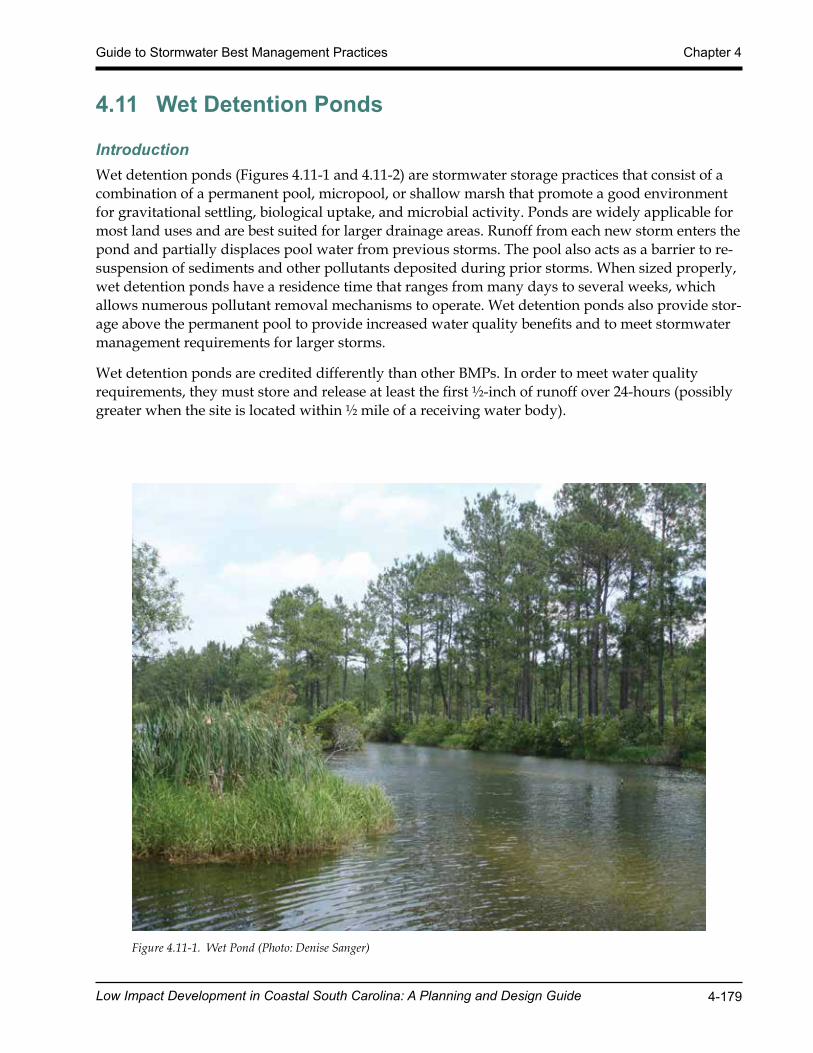
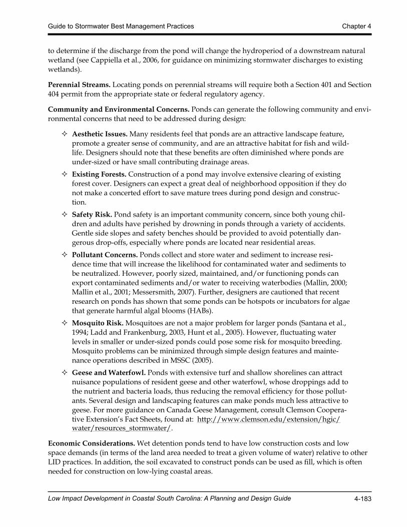
Figure 4.11-1. Wet Pond (Photo: Denise Sanger)
Low Impact Development in Coastal South Carolina: A Planning and Design Guide 4-180
Chapter 4 Guide to Stormwater Best Management Practices
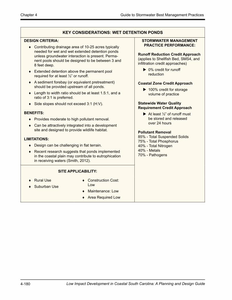
KEY CONSIDERATIONS: WET DETENTION PONDS
DESIGN CRITERIA: ♦ Contributing drainage area of 10-25 acres typically
needed for wet and wet extended detention ponds unless groundwater interaction is present. Perma-nent pools should be designed to be between 3 and 8 feet deep.
♦ Extended detention above the permanent pool required for at least ½” or runoff.
♦ A sediment forebay (or equivalent pretreatment) should be provided upstream of all ponds.
♦ Length to width ratio should be at least 1.5:1, and a ratio of 3:1 is preferred.
♦ Side slopes should not exceed 3:1 (H:V).
BENEFITS: ♦ Provides moderate to high pollutant removal. ♦ Can be attractively integrated into a development
site and designed to provide wildlife habitat.
LIMITATIONS: ♦ Design can be challenging in flat terrain. ♦ Recent research suggests that ponds implemented
in the coastal plain may contribute to eutrophication in receiving waters (Smith, 2012).
STORMWATER MANAGEMENT PRACTICE PERFORMANCE:
Runoff Reduction Credit Approach(applies to Shellfish Bed, SMS4, and infiltration credit approaches)
X 0% credit for runoff reduction
Coastal Zone Credit Approach X 100% credit for storage volume of practice
Statewide Water Quality Requirement Credit Approach
X At least ½” of runoff must be stored and released over 24 hours
Pollutant Removal85% - Total Suspended Solids75% - Total Phosphorus40% - Total Nitrogen40% - Metals70% - Pathogens
SITE APPLICABILITY:
♦ Rural Use ♦ Suburban Use
♦ Construction Cost: Low
♦ Maintenance: Low ♦ Area Required Low
Low Impact Development in Coastal South Carolina: A Planning and Design Guide 4-181
Guide to Stormwater Best Management Practices Chapter 4
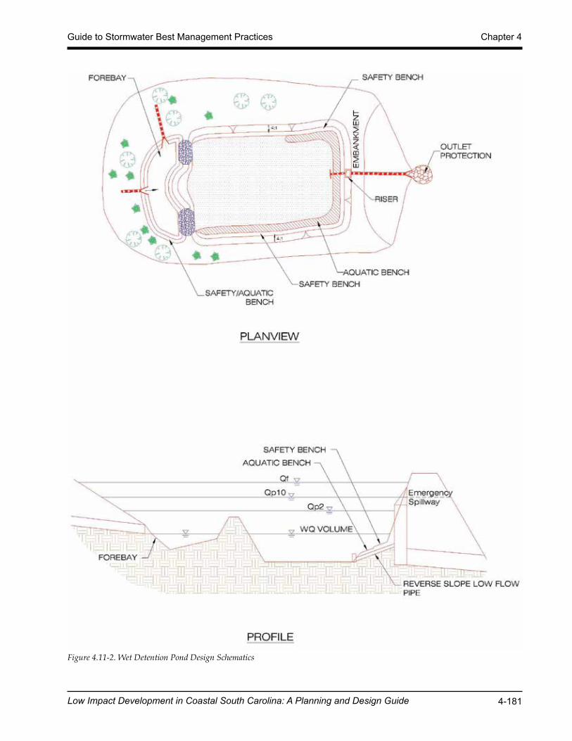
Figure 4.11-2. Wet Detention Pond Design Schematics
Low Impact Development in Coastal South Carolina: A Planning and Design Guide 4-182
Chapter 4 Guide to Stormwater Best Management Practices
Wet Detention Pond Feasibility CriteriaThe following feasibility issues need to be considered when wet ponds are considered a final storm-water management practice of the treatment train.
Adequate Water Balance. Wet detention ponds must have enough water supplied from groundwa-ter, runoff, or base flow so that the wet pools will not draw down by more than 2 feet after a 30-day summer drought. A simple water balance calculation should be performed using the equation provided in Wet Detention Pond Design Criteria.
Contributing Drainage Area. A contributing drainage area of 10 to 25 acres is typically recom-mended for ponds to maintain constant water elevations. Ponds can still function with drainage areas less than 10 acres, but designers should be aware that these “pocket” ponds will be prone to clogging, experience fluctuating water levels, and generate more nuisance conditions.
Space Requirements. The surface area of a pond will normally be at least 1% to 3% of its contribut-ing drainage area, depending on the pond’s depth.
Site Topography. Ponds are best applied when the grade of contributing slopes is less than 15%.
Available Hydraulic Head. The depth of a pond is usually determined by the hydraulic head avail-able on the site. The bottom elevation is normally the invert of the existing downstream conveyance system to which the pond discharges. However, the permanent pool may be located below this elevation. Typically, a minimum of 4 to 8 feet of head are needed to hold the wet pool and any ad-ditional large storm storage or overflow capacity for a pond to function.
Minimum Setbacks. Generally, wet ponds should be set back at least 10 feet from property lines, and 10 feet down-gradient from building foundations.
Proximity to Utilities. No utility lines should be permitted to cross any part of the embankment of a wet pond.
Depth-to-Water Table. The depth to the groundwater table is not a major constraint for wet ponds, since a high water table can help maintain wetland conditions. However, groundwater inputs can also reduce the pollutant removal rates of ponds. Further, if the water table is close to the surface, it may make excavation difficult and expensive.
Tailwater Conditions. The flow depth in the receiving channel should be considered when deter-mining outlet elevations and discharge rates from wet pond.
Soils. Highly permeable soils may make it difficult to maintain a healthy permanent pool. Soil infiltration tests need to be conducted at proposed pond sites to determine the need for a pond liner or other method to ensure a constant water surface elevation. Underlying soils of Hydrologic Soil Group (HSG) C or D should be adequate to maintain a permanent pool. Most HSG A soils and some HSG B soils will require a liner (See Table 4.11-1) or groundwater interaction. Geotechnical tests should be conducted to determine the infiltration rates and other subsurface properties of the soils beneath the proposed pond.
Use of or Discharges to Natural Wetlands. Ponds cannot be located within jurisdictional waters, including wetlands, without obtaining a section 404 permit from the appropriate state or federal regulatory agency. In addition, the designer should investigate the wetland status of adjacent areas
Low Impact Development in Coastal South Carolina: A Planning and Design Guide 4-183
Guide to Stormwater Best Management Practices Chapter 4
to determine if the discharge from the pond will change the hydroperiod of a downstream natural wetland (see Cappiella et al., 2006, for guidance on minimizing stormwater discharges to existing wetlands).
Perennial Streams. Locating ponds on perennial streams will require both a Section 401 and Section 404 permit from the appropriate state or federal regulatory agency.
Community and Environmental Concerns. Ponds can generate the following community and envi-ronmental concerns that need to be addressed during design:
� Aesthetic Issues. Many residents feel that ponds are an attractive landscape feature, promote a greater sense of community, and are an attractive habitat for fish and wild-life. Designers should note that these benefits are often diminished where ponds are under-sized or have small contributing drainage areas.
� Existing Forests. Construction of a pond may involve extensive clearing of existing forest cover. Designers can expect a great deal of neighborhood opposition if they do not make a concerted effort to save mature trees during pond design and construc-tion.
� Safety Risk. Pond safety is an important community concern, since both young chil-dren and adults have perished by drowning in ponds through a variety of accidents. Gentle side slopes and safety benches should be provided to avoid potentially dan-gerous drop-offs, especially where ponds are located near residential areas.
� Pollutant Concerns. Ponds collect and store water and sediment to increase resi-dence time that will increase the likelihood for contaminated water and sediments to be neutralized. However, poorly sized, maintained, and/or functioning ponds can export contaminated sediments and/or water to receiving waterbodies (Mallin, 2000; Mallin et al., 2001; Messersmith, 2007). Further, designers are cautioned that recent research on ponds has shown that some ponds can be hotspots or incubators for algae that generate harmful algal blooms (HABs).
� Mosquito Risk. Mosquitoes are not a major problem for larger ponds (Santana et al., 1994; Ladd and Frankenburg, 2003, Hunt et al., 2005). However, fluctuating water levels in smaller or under-sized ponds could pose some risk for mosquito breeding. Mosquito problems can be minimized through simple design features and mainte-nance operations described in MSSC (2005).
� Geese and Waterfowl. Ponds with extensive turf and shallow shorelines can attract nuisance populations of resident geese and other waterfowl, whose droppings add to the nutrient and bacteria loads, thus reducing the removal efficiency for those pollut-ants. Several design and landscaping features can make ponds much less attractive to geese. For more guidance on Canada Geese Management, consult Clemson Coopera-tive Extension’s Fact Sheets, found at: http://www.clemson.edu/extension/hgic/water/resources_stormwater/.
Economic Considerations. Wet detention ponds tend to have low construction costs and low space demands (in terms of the land area needed to treat a given volume of water) relative to other LID practices. In addition, the soil excavated to construct ponds can be used as fill, which is often needed for construction on low-lying coastal areas.
Low Impact Development in Coastal South Carolina: A Planning and Design Guide 4-184
Chapter 4 Guide to Stormwater Best Management Practices
Wet Detention Pond Conveyance CriteriaInternal Slope. The longitudinal slope of the pond bottom should be at least 0.5% to 1% to facilitate maintenance.
Primary Spillway. The spillway should be designed with acceptable anti-flotation, anti-vortex, and trash rack devices. The spillway must generally be accessible from dry land. When reinforced con-crete pipe is used for the principal spillway to increase its longevity, “O-ring” gaskets (ASTM C361) shall be used to create watertight joints.
Non-Clogging Low Flow Orifice. A low flow orifice must be provided that is adequately protected from clogging by either an acceptable external trash rack or by internal orifice protection that may allow for smaller diameters. Orifices less than 3 inches in diameter may require extra attention dur-ing design, to minimize the potential for clogging. Options include:
� A submerged reverse-slope pipe that extends downward from the riser to an inflow point 1 foot below the normal pool elevation.
� A broad crested rectangular V-notch (or proportional) weir, protected by a half-round Corrugated Metal Pipe (CMP) that extends at least 12 inches below the normal pool elevation.
Emergency Spillway. Ponds should be constructed with overflow capacity to pass the 100-year design storm event through either the primary spillway or a vegetated or armored emergency spill-way.
Adequate Outfall Protection. The design should specify an outfall that will be stable for the 10-year design storm event. The channel immediately below the pond outfall may need to be modified to prevent erosion and conform to natural dimensions in the shortest possible distance. This is typi-cally done by placing appropriately sized riprap over filter fabric, which can reduce flow velocities from the principal spillway to non-erosive levels (3.5 to 5.0 fps) depending on the channel lining material. Flared pipe sections, which discharge at or near the stream invert or into a step pool ar-rangement, should be used at the spillway outlet.
When the discharge is to a manmade pipe or channel system, the system must be adequate to con-vey the required design storm peak discharge.
If a pond daylights to a channel with dry weather flow, care should be taken to minimize tree clear-ing along the downstream channel, and to reestablish a forested riparian zone in the shortest pos-sible distance. Excessive use of riprap should be avoided.
The final release rate of the facility may need to be modified if any increase in flooding or stream channel erosion would result at a downstream structure, highway, or natural point of restricted streamflow.
Inlet Protection. Inflow points into the pond should be stabilized to ensure that non-erosive condi-tions exist during storm events up to the overbank flood event (i.e., the 10-year storm event). Inlet pipe inverts should generally be located at or slightly below the permanent pool elevation.
Low Impact Development in Coastal South Carolina: A Planning and Design Guide 4-185
Guide to Stormwater Best Management Practices Chapter 4
Wet Detention Pond Pretreatment CriteriaSediment forebays are considered to be an integral design feature to maintain the longevity of all ponds. A forebay should be located at each major inlet to trap sediment and preserve the capacity of the main treatment cell. The following criteria apply to forebay design:
� A major inlet is defined as an individual storm drain inlet pipe or open channel serv-ing at least 10% of the pond’s contributing drainage area.
� The forebay consists of a separate cell, formed by an acceptable barrier (e.g., an earthen berm, concrete weir, gabion baskets, etc.).
� The forebay should be between 4 and 6 feet deep equipped with an aquatic bench for safety purposes. The aquatic bench should be 4 to 6 feet wide at a depth of 1 to 2 feet below the water surface. Small forebays may require alternate geometry to achieve the goals of pretreatment and safety within a small area.
� The forebay should be sized to contain 0.1 inches of runoff from the contributing drainage impervious area.
� The bottom of the forebay may be hardened (e.g., with concrete, asphalt, or grouted riprap) to make sediment removal easier.
� The forebay should be equipped with a metered rod in the center of the pool (as mea-sured lengthwise along the low flow water travel path) for long-term monitoring of sediment accumulation.
� Exit velocities from the forebay should be non-erosive or an armored overflow shall be provided. Non-erosive velocities are 4 feet per second for the two-year event, and 6 feet per second for the 10-year event.
� Direct maintenance access for appropriate equipment should be provided for each forebay.
Wet Detention Pond Design CriteriaPond Storage Design: While there are no specific state requirements for the size of the permanent pool, pollutant removal can be improved by storing the equivalent of at least 0.5 inches of runoff in the permanent pool. Volume storage may be provided in multiple cells. Performance is enhanced when multiple treatment pathways are provided by using multiple cells, longer flowpaths, high surface area to volume ratios, and complex microtopography.
Pond Geometry: Pond designs should have a long flow path from inlet to outlet, to increase water residence time and pond performance. The minimum length to width ratio (i.e., length relative to width) for ponds should be 1.5:1. Greater flowpaths and irregular shapes are recommended. Inter-nal berms, baffles, or vegetated peninsulas can be used to extend flow paths and/or create multiple pond cells.
Permanent Pool Depth: The maximum depth of the permanent pool should not generally exceed eight feet unless the pond is designed for multiple uses.
Micropool: A micropool is a three to six foot deep pool used to protect the low flow pipe from clog-ging and to prevent sediment resuspension.
Low Impact Development in Coastal South Carolina: A Planning and Design Guide 4-186
Chapter 4 Guide to Stormwater Best Management Practices
Side Slopes: Side slopes for ponds should generally have a gradient no steeper than 3H:1V. Mild slopes promote better establishment and growth of vegetation and provide for easier maintenance and a more natural appearance.
Maximum Extended Detention Levels: The total storage, including any ponding for larger flood-ing events (100-year storm), should not extend more than 5 feet above the pond permanent pool unless specific design enhancements to ensure side slope stability, safety, and maintenance are identified and approved.
Stormwater Pond Benches: The perimeter of all pool areas greater than 4 feet in depth should be surrounded by two benches, as follows:
� A Safety Bench is a flat bench located just outside of the perimeter of the permanent pool to allow for maintenance access and reduce safety risks. Except when the storm-water pond side slopes are 5H:1V or flatter, provide a safety bench that generally extends 8 to 15 feet outward from the normal water edge to the toe of the stormwater pond side slope. The maximum slope of the safety bench is 5%.
� An Aquatic Bench is a shallow area just inside the perimeter of the normal pool that promotes growth of aquatic and wetland plants. The bench also serves as a safety feature, reduces shoreline erosion, and conceals floatable trash. Incorporate an aquatic bench that generally extends up to 10 feet inward from the normal shoreline, has an irregular configuration, and extends a maximum depth of 18 inches below the normal pool water surface elevation.
Liners. When a stormwater pond is located over highly permeable soils or fractured bedrock, a liner may be needed to sustain a permanent pool of water if groundwater interaction is not present. If geotechnical tests confirm the need for a liner, acceptable options include the following:
1. a clay liner following the specifications outlined in Table 4.11-12. a 30 mil poly-liner3. bentonite4. use of chemical additives5. an engineering design, as approved on a case-by-case basis by the local review au-
thorityA clay liner should have a minimum thickness of 12 inches with an additional 12-inch layer of com-pacted soil above it, and it must meet the specifications outlined in Table 4.11-1. Other synthetic lin-ers can be used if the designer can supply supporting documentation that the material will achieve the required performance.
Low Impact Development in Coastal South Carolina: A Planning and Design Guide 4-187
Guide to Stormwater Best Management Practices Chapter 4
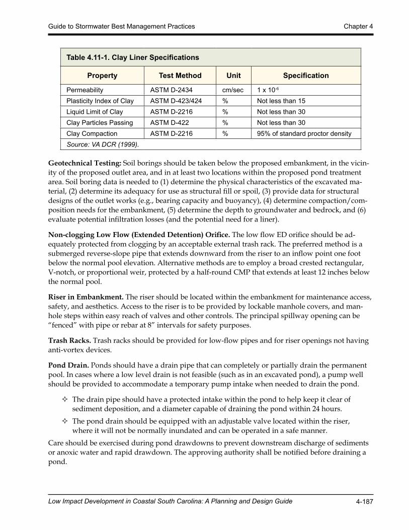
Table 4.11-1. Clay Liner Specifications
Property Test Method Unit Specification
Permeability ASTM D-2434 cm/sec 1 x 10⁻⁶
Plasticity Index of Clay ASTM D-423/424 % Not less than 15Liquid Limit of Clay ASTM D-2216 % Not less than 30Clay Particles Passing ASTM D-422 % Not less than 30Clay Compaction ASTM D-2216 % 95% of standard proctor densitySource: VA DCR (1999).
Geotechnical Testing: Soil borings should be taken below the proposed embankment, in the vicin-ity of the proposed outlet area, and in at least two locations within the proposed pond treatment area. Soil boring data is needed to (1) determine the physical characteristics of the excavated ma-terial, (2) determine its adequacy for use as structural fill or spoil, (3) provide data for structural designs of the outlet works (e.g., bearing capacity and buoyancy), (4) determine compaction/com-position needs for the embankment, (5) determine the depth to groundwater and bedrock, and (6) evaluate potential infiltration losses (and the potential need for a liner).
Non-clogging Low Flow (Extended Detention) Orifice. The low flow ED orifice should be ad-equately protected from clogging by an acceptable external trash rack. The preferred method is a submerged reverse-slope pipe that extends downward from the riser to an inflow point one foot below the normal pool elevation. Alternative methods are to employ a broad crested rectangular, V-notch, or proportional weir, protected by a half-round CMP that extends at least 12 inches below the normal pool.
Riser in Embankment. The riser should be located within the embankment for maintenance access, safety, and aesthetics. Access to the riser is to be provided by lockable manhole covers, and man-hole steps within easy reach of valves and other controls. The principal spillway opening can be “fenced” with pipe or rebar at 8” intervals for safety purposes.
Trash Racks. Trash racks should be provided for low-flow pipes and for riser openings not having anti-vortex devices.
Pond Drain. Ponds should have a drain pipe that can completely or partially drain the permanent pool. In cases where a low level drain is not feasible (such as in an excavated pond), a pump well should be provided to accommodate a temporary pump intake when needed to drain the pond.
� The drain pipe should have a protected intake within the pond to help keep it clear of sediment deposition, and a diameter capable of draining the pond within 24 hours.
� The pond drain should be equipped with an adjustable valve located within the riser, where it will not be normally inundated and can be operated in a safe manner.
Care should be exercised during pond drawdowns to prevent downstream discharge of sediments or anoxic water and rapid drawdown. The approving authority shall be notified before draining a pond.

Low Impact Development in Coastal South Carolina: A Planning and Design Guide 4-188
Chapter 4 Guide to Stormwater Best Management Practices
Adjustable Gate Valve. Both the outlet pipe and the pond drain should be equipped with an adjustable gate valve (typically a handwheel activated knife gate valve) or pump well and be sized one pipe size greater than the calculated design diameter. Valves should be located inside of the riser at a point where they (a) will not normally be inundated and (b) can be operated in a safe man-ner. To prevent vandalism, the handwheel should be chained to a ringbolt, manhole step or other fixed object.
Safety Features.
� The principal spillway opening should be designed and constructed to prevent access by small children.
� End walls above pipe outfalls greater than 48 inches in diameter should be fenced to prevent a hazard.
� Storage practices should incorporate an additional 1 foot of freeboard above the emer-gency spillway.
� The emergency spillway should be located so that downstream structures will not be impacted by spillway discharges.
� Both the safety bench and the aquatic bench should be landscaped with vegetation that hinders or prevents access to the pool.
� Warning signs prohibiting swimming should be posted. � Where permitted, fencing of the perimeter of ponds is discouraged. The preferred
method to reduce risk is to manage the contours of the stormwater pond to eliminate drop-offs or other safety hazards. Fencing is recommended at or above the maximum water surface elevation in the rare situations when the pond slope is a vertical wall.
� Side slopes to the pond should not be steeper than 3H:1V, and should terminate on a 15-foot wide safety bench. Both the safety bench and the aquatic bench may be land-scaped to prevent access to the pool. The safety bench may be omitted if slopes are 4H:1V or flatter.
Maintenance Reduction Features: The following pond maintenance issues can be addressed during the design, in order to make on-going maintenance easier:
� Maintenance Access. All ponds should be designed so as to be accessible to annual maintenance. Good access is needed so crews can remove sediments, make repairs, and preserve pond treatment capacity. • Adequate maintenance access should extend to the forebay, safety bench, riser,
and outlet structure and must have sufficient area to allow vehicles to turn around. • The riser should be located within the embankment for maintenance access, safety,
and aesthetics. Access to the riser should be provided by lockable manhole covers and manhole steps within easy reach of valves and other controls.
• Access roads should (1) be constructed of load-bearing materials or be built to withstand the expected frequency of use, (2) have a minimum width of 15 feet, and (3) have a profile grade that does not exceed 5:1.
• A maintenance right-of-way or easement should extend to the stormwater pond from a public or private road.
Low Impact Development in Coastal South Carolina: A Planning and Design Guide 4-189
Guide to Stormwater Best Management Practices Chapter 4
Pond Sizing. Wet detention ponds can be designed to capture and treat the remaining stormwater discharged from upstream practices from the design storm or used as the sole water quality BMP. Additionally, ponds should be sized to control peak flow rates from the 2-year and 10-year frequen-cy storm event or other design storms as required. Design calculations must ensure that the post-development peak discharge does not exceed the pre-development peak discharge.
For treatment train designs where upland practices are utilized for treatment of the water quality volume, designers can use a reduced Rv or CN that reflects the volume reduction of upland practic-es to compute the peak flows for the 2-year and 10-year storms (Qp2 and Qp10) that must be treated by the stormwater pond.
For water quality purposes, the storage volume, Sv, for a wet detention pond is the volume of water that is provided above the permanent pool elevation, and released slowly over 24 hours – extended detention (The Sv does not include the permanent pool or the 2-year and 10-year detention vol-umes.). To fully treat the water quality volume with at wet detention pond the Sv must be equal to ½ inch of runoff from the site. Within ½ mile from receiving water bodies, the requirement is ½ inch of runoff from the site, or 1 inch of runoff from built-upon areas, whichever is greater.
In the LID Compliance Calculator spreadsheet, wet detention ponds are not assigned any runoff reduction credit. For projects in the Coastal Zone, the Sv for wet detention ponds is given a 100% credit toward the storage requirement. For the statewide water quality requirements, wet detention ponds are credited as a pond with permanent pool, and at least ½ inch of runoff must be stored and released over 24 hours.
Water Balance Testing: A water balance calculation is recommended to document that sufficient inflows to wet ponds exist to compensate for combined infiltration and evapotranspiration losses during a 30-day summer drought without creating unacceptable drawdowns (see Equation 4.11-1, adapted from Hunt et al., 2007). The recommended minimum pool depth to avoid nuisance condi-tions may vary; however, it is generally recommended that the water balance maintain a minimum 24-inch reservoir.
Equation 4.11-1. Water Balance Equation for Acceptable Water Depth in a Wet Pond
DP > ET + INF + RES – MB
where:
DP = Average design depth of the permanent pool (inches)
ET = Summer evapotranspiration rate (inches) (assume 8 inches)
INF = Monthly infiltration loss (assume 7.2 inches @ 0.01 inch/hour)
RES = Reservoir of water for a factor of safety (assume 24 inches)
MB = Measured baseflow rate to the pond, if any (convert to inches)
Design factors that will alter this equation are the measurements of seasonal base flow and infiltra-tion rate. The use of a liner could eliminate or greatly reduce the influence of infiltration. Similarly, land use changes in the upstream watershed could alter the base flow conditions over time (e.g., urbanization and increased impervious cover).
Low Impact Development in Coastal South Carolina: A Planning and Design Guide 4-190
Chapter 4 Guide to Stormwater Best Management Practices
Translating the baseflow to inches refers to the depth within the pond. Therefore, Equation 4.11-2 can be used to convert the baseflow, measured in cubic feet per second (ft3/s), to pond-inches:
Equation 4.11-2. Baseflow Conversion
where:
MB = Measured baseflow rate to the pond (in ft3/s)
2.592 × 106 = Conversion factor: ft3/s to ft3/month.
SA = surface area of pond in ft2
Wet Detention Pond Landscaping CriteriaLandscaping and Planting Plan. A landscaping plan should be provided that indicates the meth-ods used to establish and maintain vegetative coverage in the pond and its buffer. Minimum ele-ments of a landscaping plan include the following:
� Delineation of pondscaping zones within both the pond and buffer � Selection of corresponding plant species � The planting plan � The sequence for preparing the wetland benches (including soil amendments, if needed) � Sources of native plant material � The landscaping plan should provide elements that promote diverse wildlife and
waterfowl use within the stormwater wetland and buffers. � Woody vegetation may not be planted or allowed to grow within 15 feet of the toe of
the embankment nor within 25 feet from the principal spillway structure. � A vegetated buffer should be provided that extends at least 25 feet outward from the
maximum water surface elevation of the pond. Permanent structures (e.g., buildings) should not be constructed within the buffer area. Existing trees should be preserved in the buffer area during construction.
� The soils in the stormwater buffer area are often severely compacted during the construction process, to ensure stability. The density of these compacted soils can be so great that it effectively prevents root penetration and, therefore, may lead to premature mortality or loss of vigor. As a rule of thumb, planting holes should be three times wider than the diameter of the root ball. Replacement of soils immediately below the planting hole may be beneficial as well.
� Avoid species that require full shade, or are prone to wind damage. Extra mulching around the base of trees and shrubs is strongly recommended as a means of conserv-ing moisture and suppressing weeds.
For more guidance on planting trees and shrubs in pond buffers, consult Cappiella et al (2006), as well as guidance from Clemson Cooperative Extension available at http://www.clemson.edu/ex-tension/hgic/water/resources_stormwater/.
MB × 2.592 × 106 × (12 in/ft)
SAPond Inches (per month) =
Low Impact Development in Coastal South Carolina: A Planning and Design Guide 4-191
Guide to Stormwater Best Management Practices Chapter 4
Wet Detention Pond Construction SequenceThe following is a typical construction sequence to properly install a wet detention pond. The steps may be modified to reflect different pond designs, site conditions, and the size, complexity, and configuration of the proposed facility.
Step 1: Use Ponds for Erosion and Sediment Control. A pond may serve as a sediment basin during project construction. If this is done, the volume should be based on the more stringent sizing rule (erosion and sediment control requirement vs. storage volume requirement). Instal-lation of the permanent riser should be initiated during the construction phase, and design elevations should be set with final cleanout of the sediment basin and conversion to the post-construction pond in mind. The bottom elevation of the pond should be lower than the bottom elevation of the temporary sediment basin. Appropriate procedures should be implemented to prevent discharge of turbid waters when the basin is being converted into a pond.
Step 2: Stabilize the Drainage Area. Ponds should only be constructed after the contributing drainage area to the pond is completely stabilized. If the proposed pond site will be used as a sediment trap or basin during the construction phase, the construction notes should clearly indicate that the facility will be de-watered, dredged, and re-graded to design dimensions after the original site construction is complete.
Step 3: Assemble Construction Materials on-site, make sure they meet design specifications, and prepare any staging areas.
Step 4: Clear and Strip the project area to the desired sub-grade.
Step 5: Install Erosion and Sediment Controls prior to construction, including temporary de-watering devices and stormwater diversion practices. All areas surrounding the pond that are graded or denuded during construction must be planted with turf grass, native plantings, or other approved methods of soil stabilization.
Step 6: Excavate the Core Trench and Install the Spillway Pipe.
Step 7: Install the Riser or Outflow Structure, and ensure the top invert of the overflow weir is constructed level at the design elevation.
Step 8: Construct the Embankment and Any Internal Berms in 8- to 12-inch lifts, compact the lifts with appropriate equipment.
Step 9: Excavate/Grade until the appropriate elevation and desired contours are achieved for the bottom and side slopes of the pond.
Step 10: Construct the Emergency Spillway in cut or structurally stabilized soils.
Step 11: Install Outlet Pipes, including downstream riprap apron protection.
Step 12: Stabilize Exposed Soils with temporary seed mixtures appropriate for the pond buffer. All areas above the normal pool elevation should be permanently stabilized by hydroseeding or seeding over straw.
Step 13: Plant the Pond Buffer Area, following the pondscaping plan (see Pond Landscaping Criteria).
Low Impact Development in Coastal South Carolina: A Planning and Design Guide 4-192
Chapter 4 Guide to Stormwater Best Management Practices
Construction Inspection. Multiple inspections are critical to ensure that stormwater ponds are properly constructed. Inspections are recommended during the following stages of construction:
� Pre-construction meeting � Initial site preparation (including installation of E&S controls) � Excavation/Grading (interim and final elevations) � Installation of the embankment, the riser/primary spillway, and the outlet structure � Implementation of the pondscaping plan and vegetative stabilization � Final inspection (develop a punchlist for facility acceptance)
To facilitate maintenance, contractors should measure the actual constructed pond depth at three areas within the permanent pool (forebay, mid-pond and at the riser), and they should mark them on an as-built drawing. This simple data set will enable maintenance inspectors to determine pond sediment deposition rates in order to schedule sediment cleanouts.
Wet Detention Pond Maintenance CriteriaMaintenance is needed so wet detention ponds continue to operate as designed on a long-term basis. Ponds normally have fewer routine maintenance requirements than other stormwater control measures. Pond maintenance activities vary regarding the level of effort and expertise required to perform them. Routine pond maintenance, such as mowing and removing debris and trash, is needed several times each year (See Table 4.11-3). More significant maintenance (e.g., removing accumulated sediment) is needed less frequently but requires more skilled labor and special equip-ment. Inspection and repair of critical structural features (e.g., embankments and risers) needs to be performed by a qualified professional (e.g., a structural engineer) who has experience in the con-struction, inspection, and repair of these features.
Sediment removal in the pond pretreatment forebay should occur every 5 to 7 years or after 50% of total forebay capacity has been lost. Also, sediment removal should be performed if more than 25% of the permanent pool volume is filled. The designer should check to see whether removed sedi-ments can be spoiled on-site or must be hauled away. Currently, in South Carolina, there are no re-quirements that stormwater pond sediments be tested for chemical or biological contaminants prior to sediment removal. However, sediment testing may be needed prior to sediment disposal because sediments excavated from ponds could potentially be considered toxic or hazardous (Weinstein et al., 2008). In lieu of local regulations for sediment testing, the parameters in Table 4.11-2 may be used:
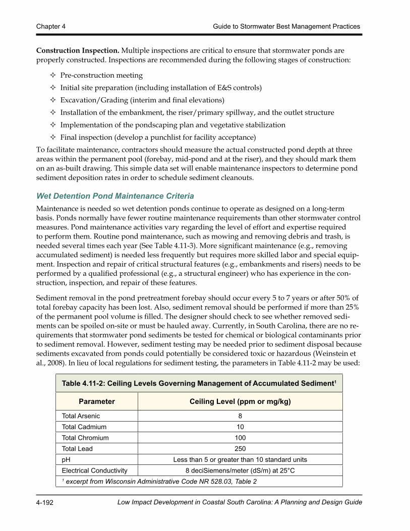
Table 4.11-2: Ceiling Levels Governing Management of Accumulated Sediment1
Parameter Ceiling Level (ppm or mg/kg)
Total Arsenic 8Total Cadmium 10Total Chromium 100Total Lead 250pH Less than 5 or greater than 10 standard unitsElectrical Conductivity 8 deciSiemens/meter (dS/m) at 25°C1 excerpt from Wisconsin Administrative Code NR 528.03, Table 2
Low Impact Development in Coastal South Carolina: A Planning and Design Guide 4-193
Guide to Stormwater Best Management Practices Chapter 4
Maintenance plans should clearly outline how vegetation in the pond and its buffer will be man-aged or harvested in the future. Periodic mowing of the stormwater buffer is only required along maintenance rights-of-way and the embankment. The remaining buffer can be managed as a mead-ow (mowing every other year) or forest. For information on chemical control methods for aquatic plants, consult Clemson’s fact sheet entitled “Aquatic Weed Control Overview” available online at http://www.clemson.edu/extension/hgic/plants/other/landscaping/hgic1714.html.
The maintenance plan should schedule a shoreline cleanup at least once a year to remove trash and floatables. More information on planting maintenance can be found in the Wetland Maintenance section.
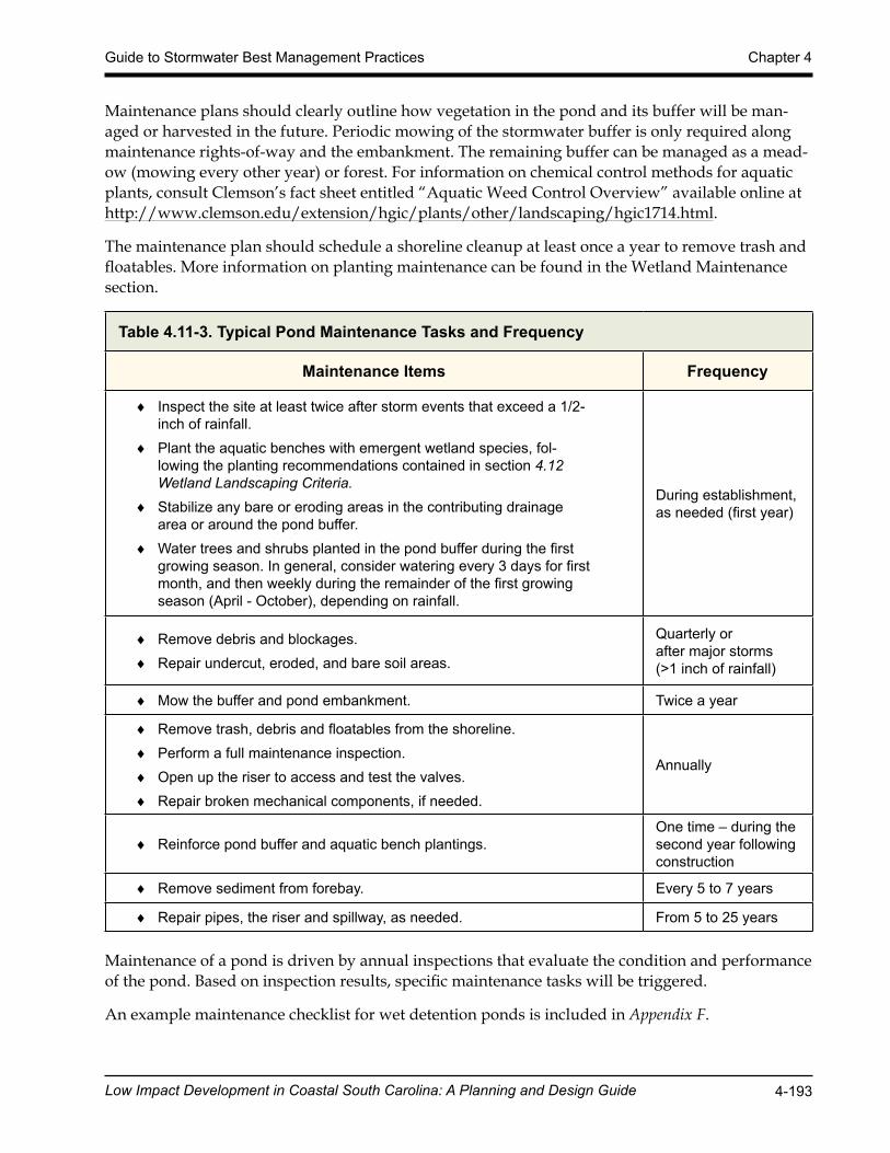
Table 4.11-3. Typical Pond Maintenance Tasks and Frequency
Maintenance Items Frequency
♦ Inspect the site at least twice after storm events that exceed a 1/2-inch of rainfall.
♦ Plant the aquatic benches with emergent wetland species, fol-lowing the planting recommendations contained in section 4.12 Wetland Landscaping Criteria.
♦ Stabilize any bare or eroding areas in the contributing drainage area or around the pond buffer.
♦ Water trees and shrubs planted in the pond buffer during the first growing season. In general, consider watering every 3 days for first month, and then weekly during the remainder of the first growing season (April - October), depending on rainfall.
During establishment, as needed (first year)
♦ Remove debris and blockages. ♦ Repair undercut, eroded, and bare soil areas.
Quarterly or after major storms(>1 inch of rainfall)
♦ Mow the buffer and pond embankment. Twice a year
♦ Remove trash, debris and floatables from the shoreline. ♦ Perform a full maintenance inspection. ♦ Open up the riser to access and test the valves. ♦ Repair broken mechanical components, if needed.
Annually
♦ Reinforce pond buffer and aquatic bench plantings. One time – during thesecond year following construction
♦ Remove sediment from forebay. Every 5 to 7 years
♦ Repair pipes, the riser and spillway, as needed. From 5 to 25 years
Maintenance of a pond is driven by annual inspections that evaluate the condition and performance of the pond. Based on inspection results, specific maintenance tasks will be triggered.
An example maintenance checklist for wet detention ponds is included in Appendix F.
Low Impact Development in Coastal South Carolina: A Planning and Design Guide 4-194
Chapter 4 Guide to Stormwater Best Management Practices
Wet Detention Pond References and Additional Resources
1. Atlanta Regional Commission (ARC). 2001. Georgia Stormwater Management Manual, First Edition. Available online at: http://www.georgiastormwater.com
2. Cappiella, K., T. Schueler and T. Wright. 2006. Urban Watershed Forestry Manual: Part 2: Conserving and Planting Trees at Development Sites. USDA Forest Service. Center for Watershed Protection. Ellicott City, MD.
3. Hunt, W., C. Apperson, and W. Lord. 2005. “Mosquito Control for Stormwater Facilities.” Urban Waterways. North Carolina State University and North Carolina Cooperative Ex-tension. Raleigh, NC.
4. Hunt, W., M. Burchell, J. Wright and K. Bass. 2007. “Stormwater Wetland Design Update: Zones, Vegetation, Soil and Outlet Guidance.” Urban Waterways. North Carolina State Cooperative Extension Service. Raleigh, NC.
5. Ladd, B and J. Frankenburg. 2003. Management of Ponds, Wetlands and Other Water Res-ervoirs. Purdue Extension. WQ-41-W.
6. Mallin, M. 2000. Effect of human development on bacteriological water quality in coastal watersheds. Ecological Applications 10(4):1047-1056.
7. Mallin, M.A., S.H. Ensign, Matthew R. McIver, G. Christopher Shank, and Patricia K. Fowler. 2001. Demographic, landscape, and meteorological factors controlling the micro-bial pollution of coastal waters. Hydrobiologia 460(1-3):185-193.
8. Messersmith, M.J. 2007. Assessing the hydrology and pollutant removal efficiencies of wet detention ponds in South Carolina. MS. Charleston, S.C. College of Charleston, Master of Environmental Studies.
9. Minnesota Stormwater Steering Committee (MSSC). 2005. Minnesota Stormwater Manual. Emmons & Oliver Resources, Inc. Minnesota Pollution Control Agency. St. Paul, MN.
10. Santana, F., J. Wood, R. Parsons, and S. Chamberlain. 1994. Control of Mosquito Breeding in Permitted Stormwater Systems. Southwest Florida Water Management District. Brooks-ville, FL.
11. Schueler, T, 1992. Design of Stormwater Wetland Systems. Metropolitan Washington Council of Governments. Washington, DC.
12. Smith, E.M. 2012. Nutrient-Organic Matter Dynamics in Stormwater ponds: Implications for Stormwater Management and the Role of Ponds as Sources of Coastal Water Qual-ity Impairment. Paper presented at the South Carolina Water Resources Conference, Columbia SC. Available online at: http://tigerprints.clemson.edu/cgi/viewcontent.cgi?article=1060&context=scwrc
13. Virginia Department of Conservation and Recreation (VA DCR). 2011. Stormwater De-sign Specification No. 14: Wet Ponds Version 1.8. Available at http://vwrrc.vt.edu/swc/april_22_2010_update/DCR_BMP_Spec_No_14_WET_PONDS_Final_Draft_v1-8_04132010.htm
14. Virginia Department of Conservation and Recreation (VA DCR). 2011. Stormwater Design Specification No. 15: Extended Detention (ED) Pond Version 1.8. http://vwrrc.vt.edu/swc/april_22_2010_update/DCR_BMP_Spec_No_15_EXT_DETENTION_POND_Final_Draft_v1-8_04132010.pdf
Low Impact Development in Coastal South Carolina: A Planning and Design Guide 4-195
Guide to Stormwater Best Management Practices Chapter 4
15. Virginia Department of Conservation and Recreation (VA DCR). 1999. Virginia Stormwa-ter Management Handbook, first edition.
16. Orscheln, N., and Giacolne, K., 2013 Resident Canada Geese: Management Options. SC-Waterways. Clemson Cooperative Extension. Available online at: http://www.clemson.edu/extension/hgic/water/resources_stormwater/
17. Weinstein, J.E., K.D. Crawford, and T.R. Garner. 2008. Chemical and Biological Contami-nation of Stormwater Detention Pond Sediments in Coastal South Carolina. Available at http://www.scseagrant.org/pdf_files/SC_stormwater_rpt.pdf
18. Wisconsin Administrative Code NR 528. 2012. Management of Accumulated Sediment from Storm Water Management Structures. Available at http://docs.legis.wisconsin.gov/code/admin_code/nr/500/528.pdf