Embed Size (px)
Citation preview
cd C-
418 2 P; 4 2 z
RESEARCH MEMORANDUM
NACA
INVESTIGATION O F SPOILER AILERONS WITH AND WITHOUT A GAP
BERIND THE SPOILER ON A 45' SWEPTBACK WING-FUSELAGE
COMBINATION AT MACH NUMBERS FROM 0.60 T O 1.03 0\ cv rl
By F. E. West , Jr., William Solomon, and Edward M. rumm male
Langley Aeronautical Laboratory 8 G
Langley Field, Va.
FIED DOCUM&NT
he National Defense of the U&d States wit& the meading 708 end 194, the transmissloa or revelation of which in aqy
m a r to an UltauUlorked person is prohibited by law.
NATIONAL ADVISORY COMMITT FOR AERONAUTICS
WASHINGTON September 14, 1953
CON F, rl*; AZJi
Restriction/Classification Cancelled
Restriction/Classification Cancelled
Restriction/Classification Cancelled
Restriction/Classification Cancelled
https://ntrs.nasa.gov/search.jsp?R=19930087817 2018-07-01T20:45:05+00:00Z
R NACA RM L53G07a Tm
NATIONAL ABVISORY COMMITTEE FOR AERONAUTICS
RESEARCH moRANDUM
INVESTIGATION OF SPOILER AIL;ERONS WITH AM) WITHOUT A GAP
BEHIND TKE SPOILER ON A 45' SWEPTBACK WING-FUSELAGE
COMBINATION AT MACH IWMEEBS FROM 0 .60 TO 1 .03
By F. E. West, Jr ., W i l l i a m Solomon, and Edward M . Brummal
SUMMARY
An invest igat ion was conducted with severa l 73-percent semispan inboard spo i le r a i lerons , project ing 4 percent of the l o c a l wing chord from the wing surface, and located a t t h e 70-percent chord l i n e of a 45' sweptback wing-fuselage combination. The model consisted of a wing with an aspect r a t i o of 3.98, t aper r a t i o of 0.61, and NACA 65~006 a i r f o i l sect ions p a r a l l e l t o the plane of symmetry i n combination with a b l u n t - t a i l fuselage of f ineness r a t i o 10. Six-component force da t a were obtained during the invest igat ion i n the Langley 16-foot t ransonic
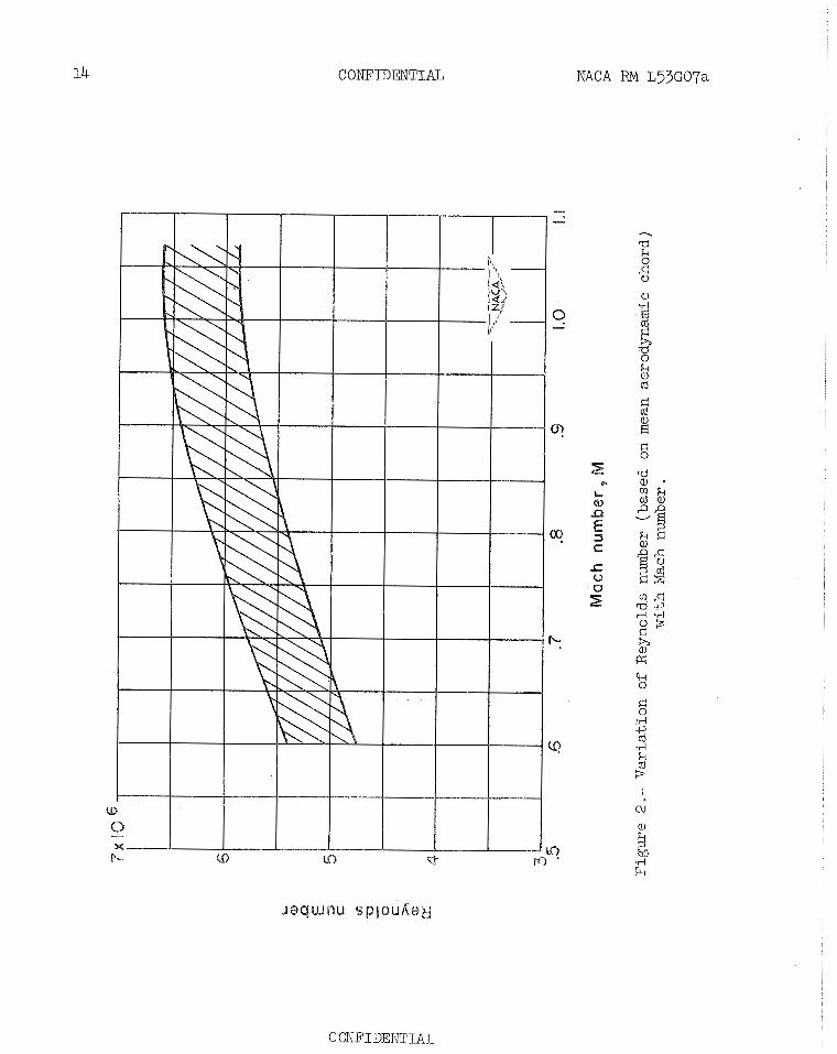
tunnel a t Mach numbers from 0.60 ( ~ e y n o l d s number of 5.1 x 10⁶) t o 1 .03 ( ~ e ~ o l d s number of 6.2 x 10⁶) f o r an angle-of-attack range of approxi- mately -2O t o 26O.
Although upper-surface-spoiler configurations with a gap i n t h e wing behind the spo i l e r l o s t rolling-moment effect iveness above an angle of a t t ack of 60, they did r e t a i n some effectiveness even at high angles of a t t ack f o r the e n t i r e transonic speed range, whereas an upper-surface- spo i l e r configuration without a gap l o s t complete effect iveness a t high angles of a t t ack fo r most Mach numbers. The upper-surface-spoiler ef fec- t iveness increased with increase i n width of the wing gap. Although a t low angles of a t t a ck the influence of wing-gap width decreased with increase i n Mach number, l i t t l e change i n the influence of the gap width occurred a t high angles of a t t ack . A lower-surface spo i le r was l e s s e f fec t ive than a corresponding upper-surface spo i l e r a t low angles of a t t ack and produced a subs tan t ia l r o l l i n g moment i n the reversed d i r ec t i on a t high angles of a t t ack . Two oppositely def lected spo i le r s were found t o be usefu l mainly i n the lower angle-of-attack'range where the r o l l i n g moment produced was much greater than fo r a s ingle upper-surface spo i l e r .
Restriction/Classification Cancelled
Restriction/Classification Cancelled
CONFIDENTIAL NACA RM L33G07a
INTRODUCTION
Because flap-type ailerons on sweptback wings lose effectiveness with approach t o transonic speeds, as indicated i n reference 1, the need has existed for a la teral-control device which would r e t a in effectiveness throughout the speed and angle-of-attack range. Spoiler ailerons have been shown t o be effect ive on sweptback wings and t h e i r effectiveness has been found t o increase through the transonic speed range. (see reference 2.) I n addition, spoiler ailerons can be designed with very low hinge moments and they tend t o produce l e s s wing t w i s t than conven- t i ona l flap-type ai lerons. Although numerous investigations of spoi lers have been conducted a t low speeds, most of the spoiler investigations a t transonic speeds have been conducted a t low angles of a t tack and low Reynolds numbers. or example, see r e f . 2 . ) A systematic t e s t program has therefore been in i t i a t ed i n the Langley 16-foot transonic tunnel t o obtain force and pressure data for various spoiler configurations i n the transonic speed range a t moderately high Reynolds numbers and over a wide range of angle of a t tack. The i n i t i a l investigation of t h i s program has been conducted on a 4 5 O sweptback wing-fuselage combination a t 0' yaw and a Mach number range from 0.60 t o 1.03.
The spoi lers investigated were of the retractable type and extended along the 70-percent chord l ine from the fuselage (o r 14 percent of the wing semispan) t o 87 percent of the wing semispan and were projected from the wing surface 4 percent of the loca l wing chord. This paper presents the six-component force- test resu l t s which were obtained during t h i s i n i t i a l investigation. Aerodynamic character is t ics a re shown for an upper-surface- spoiler configuration having various widths of gap i n the wing behind the spoiler, fo r a lower-surface spoiler alone, and fo r a lower-surface spoiler i n combination with an upper-surface spoi ler . A comparison i s also made between spoiler effectiveness and flap-type ai leron effectiveness over the Mach number range.
The forces and the moments are presented about the wind axes which have the i r or igin a t the intersection of the plane of symmetry and a point which corresponds t o the 25-percent-chord s ta t ion of the mean aerodynamic chord.
b wing span
loca l wing chord
wing mean aerodynamic chord
CONFIDENT6AZ,
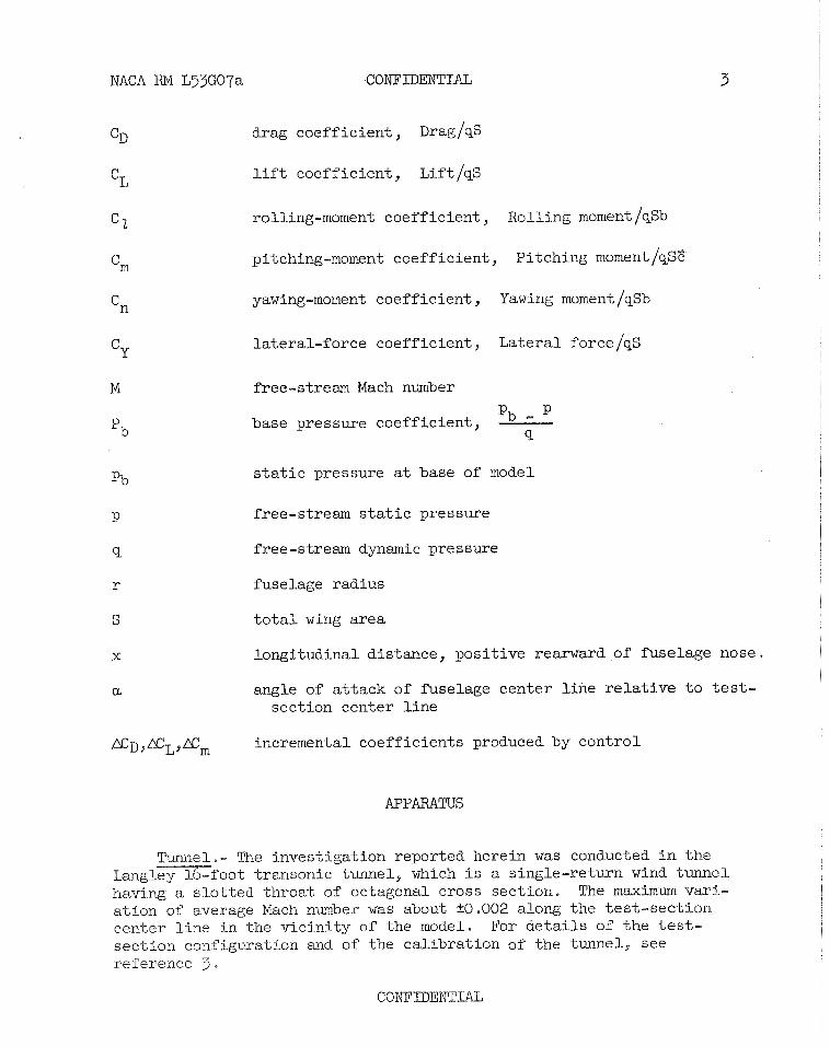
C~ drag coefficient, Drag/@
lift coefficient , ~ i f t / q ~
2 rolling-moment coefficient , Rolling moment /qsb
'm pitching-moment coefficient, Pitching moment IqsE
n yawing-moment coefficient , Yawing moment Iqsb
C~ lateral-f orce coefficient , Lateral force Iqs
M free-stream Mach number
base pressure coefficient, Pb - p pb
Po static pressure at base of model
P free-stream static pressure
9 free-stream dynamic pressure
r fuselage radius
S total wing area
x longitudinal distance, positive rearward of fuselage nose.
angle of attack of f'uselage center line relative to test- section center line
gD,XL9Em incremental coefficients produced by control
APPARATUS
!Tunnel.- The investigation reported herein was conducted in the Eang oot transonic tunnel, which is a single-return wind tunnel having a slotted throat of octagonal cross section. The maximum vari- ation of average Ma.ch number was about S . 0 0 2 along the test-section center line in the vicinity of the model. For details of the test- section configuration and of the calibration of the tunnel., see reference 3.
4 COWFIDENT%AL NACA RM L53G07a
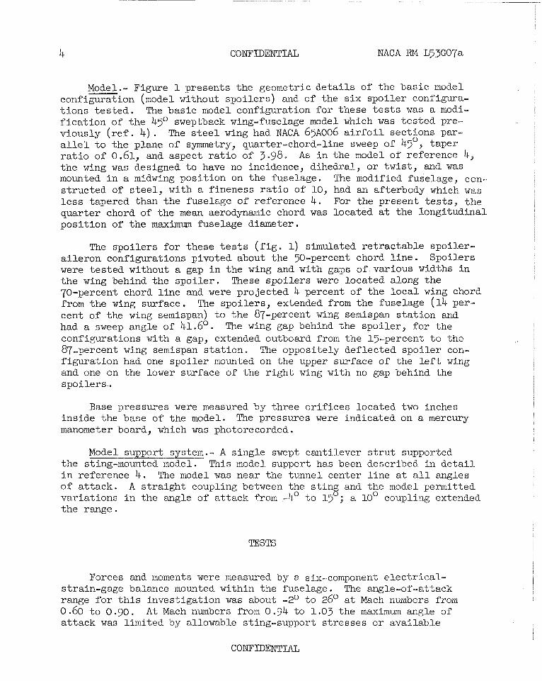
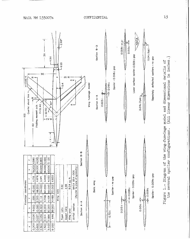
Model.- Figure 1 presents the geometric d e t a i l s of the bas ic model configuration (model without spo i le r s ) and of the s i x spo i le r configura- t i o n s t e s t e d . The bas ic model configuration f o r these t e s t s was a modi- f i c a t i o n of t he 4 5 O sweptback wing-fuselage model which w a s t e s t ed pre- viously ( r e f . 4) . The s t e e l wing had NACA 65~006 a i r f o i l sect ions par- a l l e l t o the plane of symmetry, quarter-chord-line sweep of 45°, taper r a t i o of 0.61, and aspect r a t i o of 3.98. As i n the model of reference 4, t h e wing was designed t o have no incidence, dihedral , o r tw i s t , and w a s mounted i n a midwing pos i t ion on the fuselage. The modified fuselage, con- s t ruc ted or s t e e l , with a f ineness r a t i o of 10, had an afterbody which was l e s s tapered than t he fuselage of reference 4. For the present t e s t s , t he quar ter chord of the mean aerodynamic chord w a s located at the longi tudinal pos i t ion of t he maximum fuselage diameter.
The spo i le r s f o r these t e s t s ( f i g . 1) simulated r e t r ac t ab l e spoi ler- a i l e ron configurations pivoted about the 50-percent chord l i n e . Spoi lers were t e s t e d without a gap i n the wing and with gaps of various widths i n t h e wing behind t he spo i l e r . These spo i le r s were located along t h e 70-percent chord l i n e and were projected 4 percent of t h e l o c a l wing chord from the wing surface. The spo i le r s , extended from the fuselage (14 per- cent of the wing semispan) t o t he 87-percent wing semispan s t a t i o n and had a sweep angle of 41.6'. The wing gap behind the spo i le r , f o r the configurations with a gap, extended outboard from the 15-percent t o the 87-percent wing semispan s t a t i on . The oppositely def lected spo i le r con- f igura t ion had one spo i le r mounted on the upper surface of the l e f t wing and one on the lower surface of the r i g h t wing with no gap behind the spoilers. .
Base pressures were measured by three o r i f i c e s located two inches ins ide the base of the model. The pressures were indicated on a mercury manometer board, which was photorecorded.
.- A s ingle swept cant i lever s t r u t supported the sting-mounted model. This model support has been described i n d e t a i l i n reference 4 . The model was near the- tunnel center l i n e a t a l l angles of a t t a ck . A s t r a igh t coupling between the s t i ng and the model permitted var ia t ions i n the angle of a t t ack from -4' t o 15 ; a 10' coupling extended t he range.
Forces and moments were measured by a six-component e l e c t r i c a l - strain-gage balance mounted within the fuselage . The angle-of -at tack range f o r t h i s invest igat ion was about -2O t o 26O a t Mach numbers from 0.60 t o 0.90. A t Mach numbers from 0.94 t o 1.03 the maximum angle of a t t a ck was l imi ted by allowable sting-support s t resses o r avai lable
tunnel power. For example, the maximum angle of a t t ack was usual ly about 12O at a Mach number of 1 .03, A few configurations were t e s t ed t o a Mach number of 1.07 a t 0' angle of a t tack, and a few t e s t s with t he ba s i c model were extended t o -4' angle of a t t ack . The Reynolds number va r i a t i on over the speed range of the t e s t s is shown i n f igure 2 .
PPiECISION AND CORRECTIONS
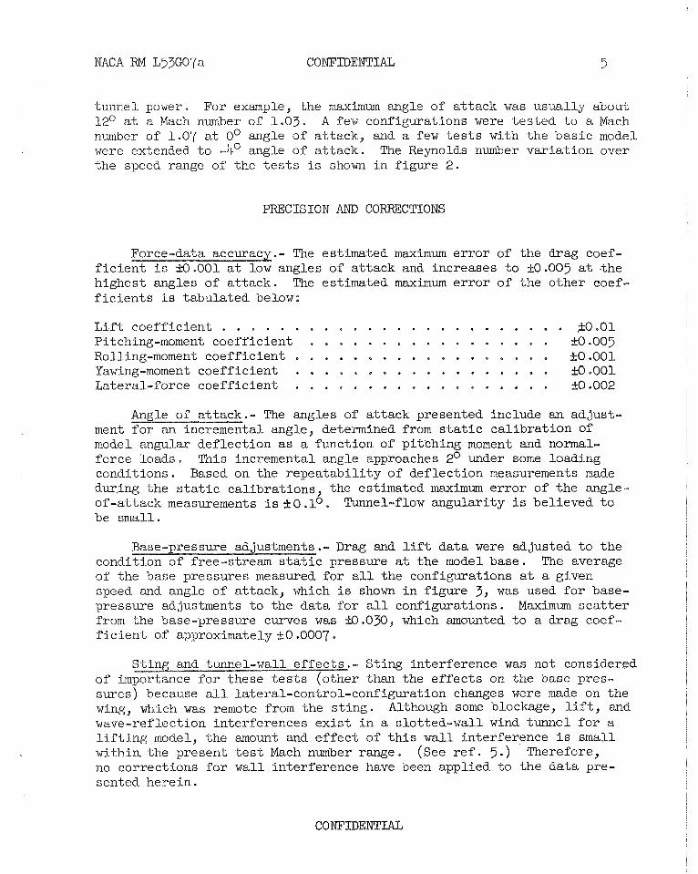
.- The estimated maximum e r r o r of the drag coef- f i c i e n t i s 10.001 a t low angles of a t t ack and increases t o kO .OO5 at .the highest angles of a t t ack . The estimated maximum e r r o r of t he o ther coef- f i c i e n t s i s tabula ted below:
L i f t coef f ic ien t . . . . . . . . . . . . . . . . . . . . . . . . f O . O 1 Pitching-moment coef f ic ien t . . . . . . . . . . . . . . . . . B . 0 0 5 Rolling-moment coef f ic ien t . . . . . . . . . . . . . . . . . . 10.001 Yawing-moment coef f ic ien t . . . . . . . . . . . . . . . . . . kO.001 Lateral-force coef f ic ien t . . . . . . . . . . . . . . . . . . k0.002
Angle of a t t ack .- The angles of a t t ack presented include an adjust - ment f o r an incremental angle, determined from s t a t i c c a l i b r a t i on of model angular def lec t ion a s a function of p i tching moment and normal- force loads. This incremental angle approaches 2O under some loading condit ions. Based on the r epea t ab i l i t y of def lec t ion measurements made dur,ing t he s t a t i c ca l ib ra t ions , the estimated maximum e r r o r of the angle- of-a t tack measurements isf0.10. Tunnel-flow angular i ty i s believed t o be small .
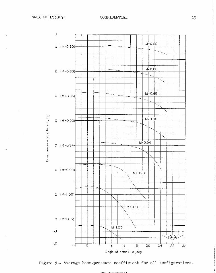
.- Drag and l i f t da ta were adjusted t o t he condition of free-stream s t a t i c pressure a t t he model base. The average of the base pressures measured f o r a l l the configurations at a given speed and angle of a t tack, which i s shown i n f igure 3, was used f o r base- pressure adjustments t o the data f o r a l l configurations. Maximum s c a t t e r from the base-pressure curves w a s 9 . 0 3 0 , which amounted t o a drag coef- f i c i e n t of approximately .+_0.0007.
.- Sting in terference was not considered r than the e f f e c t s on t he base pres-
sures) because a l l lateral-control-conf igurat ion changes were made on t he wing, which was remote from the s t i ng . Although some blockage, l i f t , and wave-reflection in terferences e x i s t i n a s lo t ted-wal l wind tunnel f o r a l i f t i n g model, the amount and e f f e c t of t h i s w a l l in terference i s small wi thin the present t e s t Mach number range. ( see r e f . 5 . ) Therefore, no corrections f o r wall in terference have been applied t o t h e da ta pre- sented herein .
NACA PIM L_5jG07a
RESULTS AND DISCUSSION
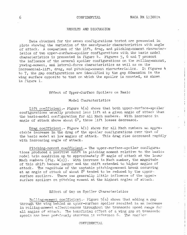
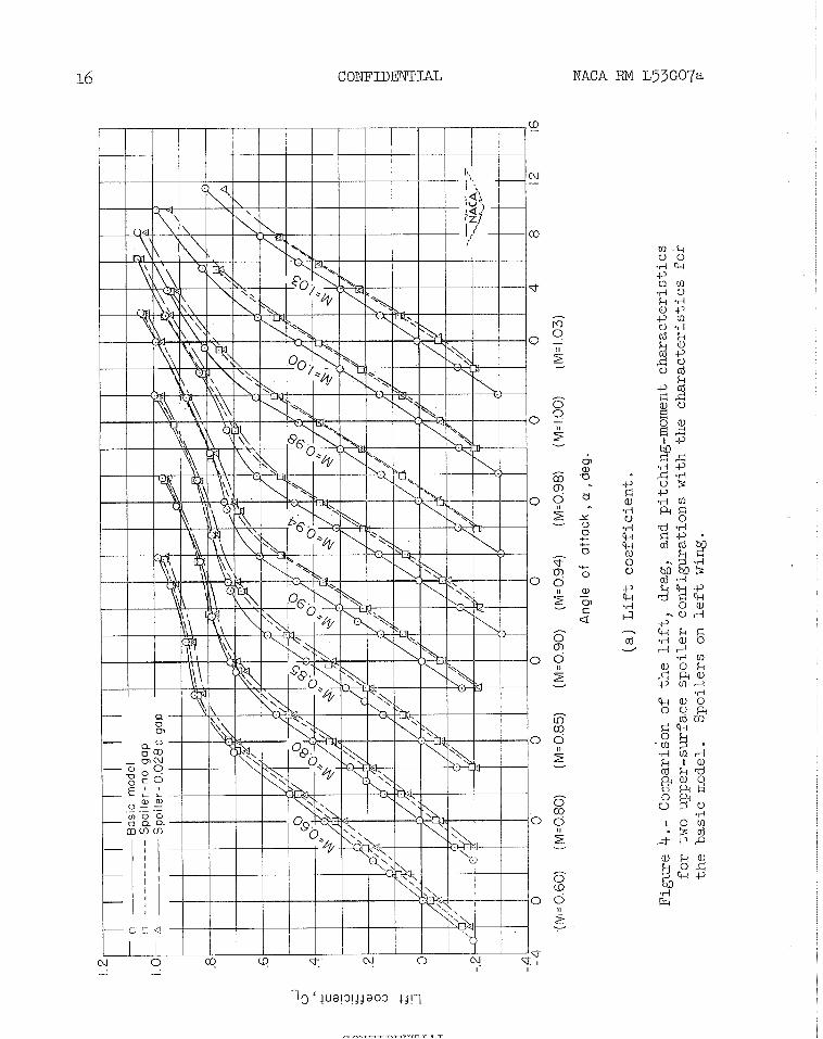
Data obtained for the seven configurations tested are presented in plots showing the variation of the aerodynamic characteristics with angle of attack. A comparison of the lift, drag, and pitching-moment character- istics of two upper-surface-spoiler configurations with the basic model characteristics is presented in figure 4. Figures 5, 6 and 7 present the influence of the several spoiler configurations on the rolling-moment, yawing-moment, and lateral-force characteristics as well as on the incremental-lift, drag, and pitching-moment characteristics. In figures 4 to 7, the gap configurations are identified by the gap dhension in the wing surface opposite to that on which the spoiler is mounted, as shown in figure 1.
Effect of Upper-Surface Spoilers on Basic
Model Characteristics
Lift coefficient . - Figure 4(a) shows that both upper-surf ace-spoiler confiwations usually produced less lift at a given angle of attack than - " - the basic-model configuration for all Mach numbers. With increases in angle of attack above about 6O, these lift losses decreased.
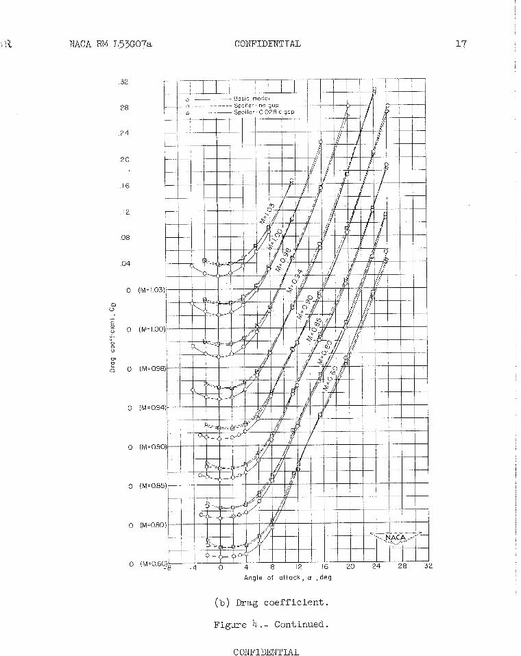
Drag coefficient.- Figure 4(b) shows for all Mach numbers an appre- ciable increase in the drag of the spoiler configurations over that of the basic model at low angles of attack. This drag rise decreased rapidly with increasing angle of attack.
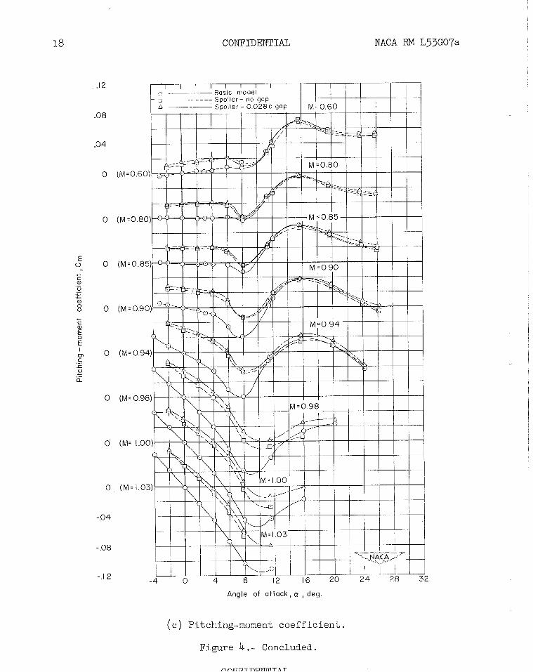
Pitching-moment coefficient . - The upper-surface-spoiler conf igura- tions produced a positive shift in pitching moment relative to the basic- model trim condition up to approximately 80 angle of attack at the lower Mach numbers (fig . 4(c) ) . With increase in Mach number, the magnitude of this shift became larger and the shift extended to higher angles of attack. The magnitude of the unstable pitching-moment break occurring at an angle of attack of about 8' tended to be reduced by the upper- surface spoilers. There was generally little influence of the upper- surface spoilers on pitching moment at the highest angles of attack.
Effect of Gap on Spoiler Characteristics
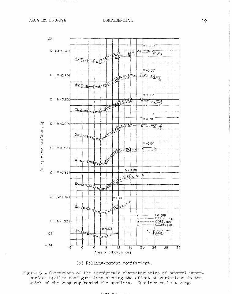
Rolling-moment coeff iclent . - Figure >(a) shows that adding a gap through the wing behind an upper-surface spoiler resulted in an increase in rolling-moment effectiveness throughout the transonic speed range for a11 angles of attack. The beneficial effect of a wing gap at transonic speeds has been previously observed in reference 6. The spoiler
NACA RM L53G07a CONFIDENTIAL 7'
configuration with no wing gap generally became inef fec t ive a t an angle of a t t ack of 160. Although the spo i le r configurations with wing gaps experienced a l o s s of effect iveness above an angle of a t t a ck of 6' ( f i g . ? ( a ) ) , they generally, however, d id r e t a i n a small amount of effec- t iveness even a t t he high angles of a t t a ck .
The decrease i n rolling-moment effect iveness with increase i n angle of a t t ack above 6' may not necessar i ly be accompanied by a proportional decrease i n t he r a t e of r o l l . Reference 7, which presents data up t o a Mach number of 0.93, shows t h a t the damping i n r o l l of a 4.5' sweptback wing configuration decreases at the higher angles of a t t a ck . This reduced damping i n r o l l could possibly allow a s a t i s f ac to ry r a t e -o f r o l l even a t the low values of rolling-moment coef f ic ien t developed by t he spo i l e r configurations a t high angles of a t t ack .
Figure >(a) a l so shows t h a t the rolling-moment effect iveness of the spo i l e r configurations increased with increase of the lower-surface gap width throughout t he angle-of-attack and Mach number range. Hence, it appears t h a t f u r t he r increases i n the lower-surface gap width would r e s u l t i n increased rolling-moment effect iveness as long a s the upper-surface gap remained above some c r i t i c a l width. The inf luerce of t he gap width on r o l l i n g moment decreased with increase i n Mach nnxber at low angles of a t t ack ( f i g . ? ( a ) ) . L i t t l e change occurred i n the gap effect iveness with increase i n Mach number a t the high angles of a t t ack .
Study of the r e s u l t s indicated t h a t the one change i n upper-surface gap width had no apparent e f f e c t on rolling-moment e f fec t iveness . Con- jec ture a s t o t he reason the lower-surface gap i s m important parameter leads t o the assumption t h a t t h i s gap a c t s a s a f l u sh air scoop. Such a scoop would tend t o have an increased influence as the angle of a t t ack was increased.
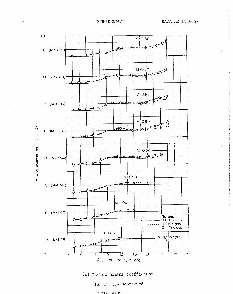
Yawing-moment coef f ic ien t . - The yawing moment f o r upper-surface spo i le r s below an angle of a t t ack of about 12O was found t o be e i t h e r s l i g h t l y favorable o r negl igible throughout the t e s t Mach number range ( f i g 5 ) ) A t the higher angles of a t tack, the upper-surface spo i le r s tended t o produce a s l i g h t adverse yawing moment. Gap width had no s ig- n i f i c an t e f f ec t below an angle of a t t ack of approximately 12'. Above 12O use of a gap tended t o make the yawing moment more adverse than f o r t he spo i le r with no gap.
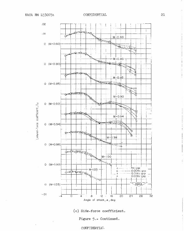
Lateral-force coef f ic ien t . - A l l upper-surface-spoiler configurations tended t o produce a pos i t ive l a t e r a l force at the low and intermediate angles of a t t a ck w i t h l i t t l e e f f ec t of gap s ize , f igure ? ( c ) . A t angles of a t t ack above approximately lgO a negative l a t e r a l force w a s produced.
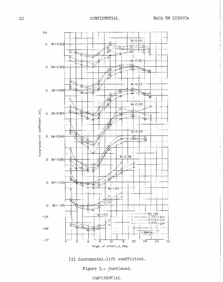
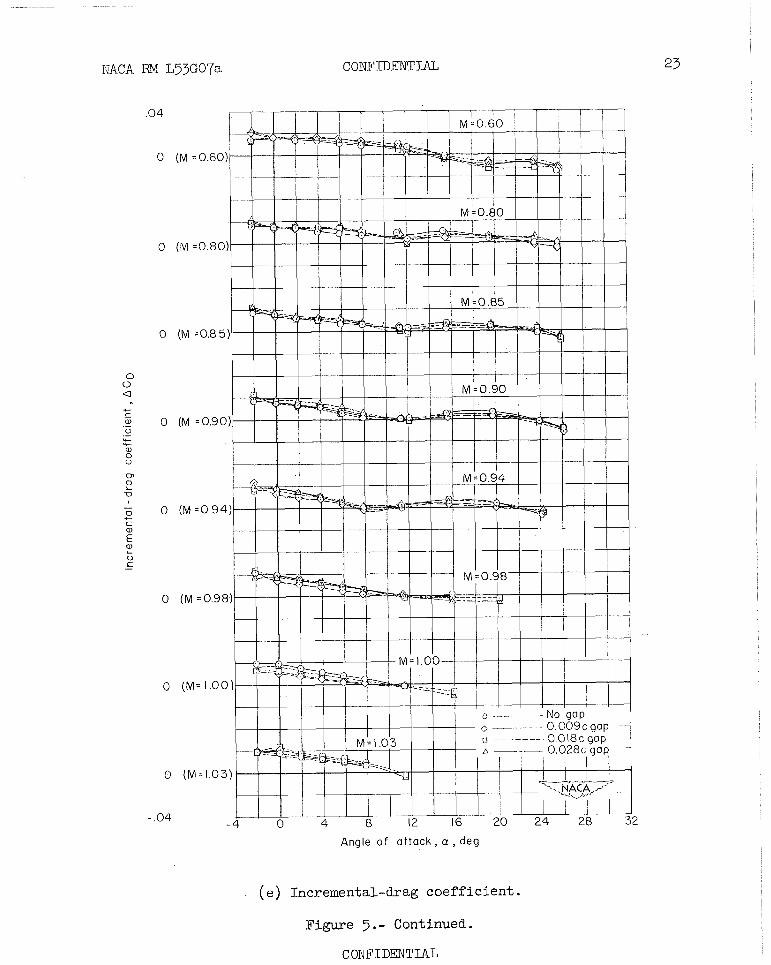
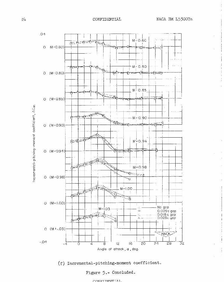
.- The e f f e c t s of gap width on incremental-l if t , incremental-drag and
incremental-pitching-moment caef f ic ien t s shown i n f igures 5 (d ) , 5 ( e ) , and 5 ( f ) , respect ively , showed l i t t l e difference from the e f f e c t s noted i n f igure 4 f o r only two spo i le r configurations. I n general; the l i f t l o s s was greater f o r the configurations with a wing gap than f o r t he configuration with no wing gap, but there was no apparent t rend with gap width. There was negl igible e f f e c t of gap width on incremental-drag coe f f i c i en t . Increases i n gap width, however, had a tendency t o increase t he pos i t ive pitching-moment increment a t the higher angles of a t t a ck and Mach numbers .
Comparison of Upper- and Lower-Surface
Spoiler Character is t ics
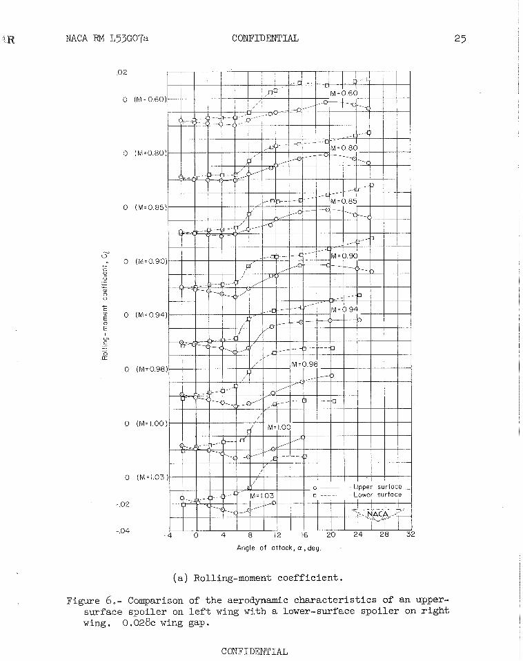
Rolling-moment coeff ic ient .- In f igure 6 ( a ) , it i s shown t h a t the lower-surface spo i le r with 0.028 chord gap was l e s s e f f ec t i ve than the corresponding upper-surface spo i l e r . The lower-spface spo i l e r tended t o reverse rolling-moment effect iveness between 8 and lo0. angle of a t t ack and t o produce a subs tan t ia l r o l l i n g moment i n the reversed disec- t i o n a t the higher angles of a t t a ck .
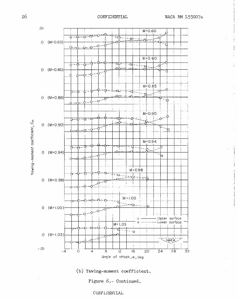
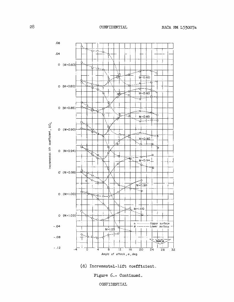
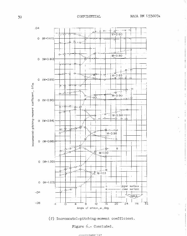
Other coef f ic ien t s .- Figure 6(b) shows t h a t the lower-surface spo i le r produced an adverse yawing moment over almost the e n t i r e Mach number range and angle-of-attack range t e s t ed . The magnitude of t h i s adverse yaw near an angle of a t t ack of 0' was approximately equal t o t h a t of the favorable yaw produced by the upper-surface spo i l e r . L i f t and pitching- moment increments ( f i g s . 6(d) and ( f ) , respectively) produced by the lower-surface spo i le r exhibited a reversa l of sign a t approximately the same angles of a t t ack a t which r o l l i n g moment showed reversa l s of s ign. Since the basic model tended t o develop a pitch-up s t a r t i n g i n t h e region of 8' t o lo0 angle of a t t ack ( see f i g . 4 ( c ) ) , t he reversa l of s ign of the incremental p i tching moment (from negative t o pos i t i ve ) , f igure 6 ( f ) , ind ica tes t h a t t he pitch-up would be more severe f o r the configuration with t he lower-surface spo i le r than fo r the bas ic model. A t moderate angles of a t t ack the drag increment produced by the lower-surface spo i le r ( f i g . 6(c) ) was la rger than t h a t produced by the upper-surface spo i l e r .
Comparison of Upper-Surface Spoiler W i t h
Oppositely Deflected Spoi lers
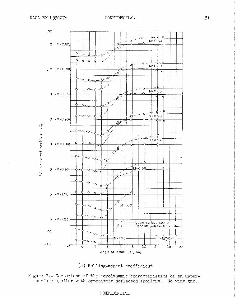
- The oppositely def lected spo i le r s , 114% moments than a s ingle upper-surface
spo i le r up t o angles of a t tack of approximately lo0 a t which angle it was noted i n the discussion of f igure 6 (a ) t h a t a lower-surface spo i l e r tended t o reverse effect iveness . ( N O gap was used i n the wing f o r the
NACA RM L53G07a CONFIDENTSAL 9
oppositely deflected and the upper-surface spoilers discussed herein.) At the higher angles of attack the oppositely deflected spoiler config- uration tended to reverse effectiveness as would be expected since fig- ure 6(a) indicates that a lower-surface spoiler produced a substantial rolling moment in the reversed direction. This oppositely deflected spoiler-configuration would, therefore, be useful only in the lower angle-of-attack range.
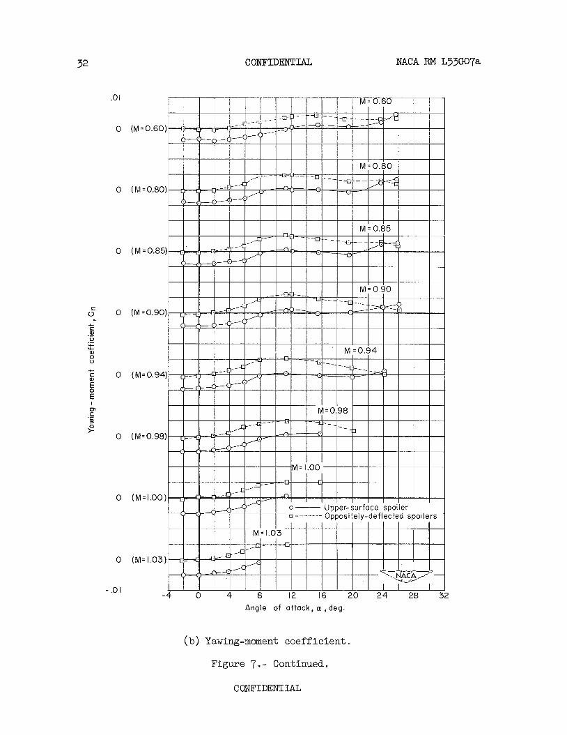
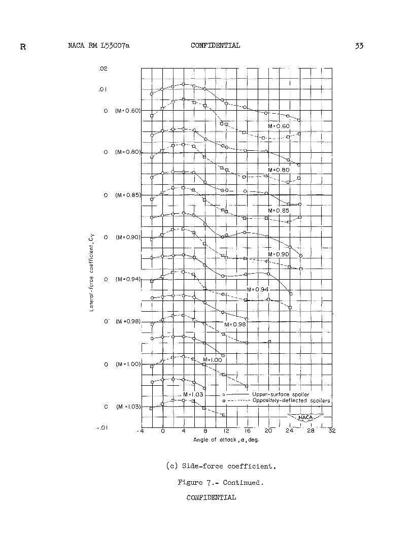
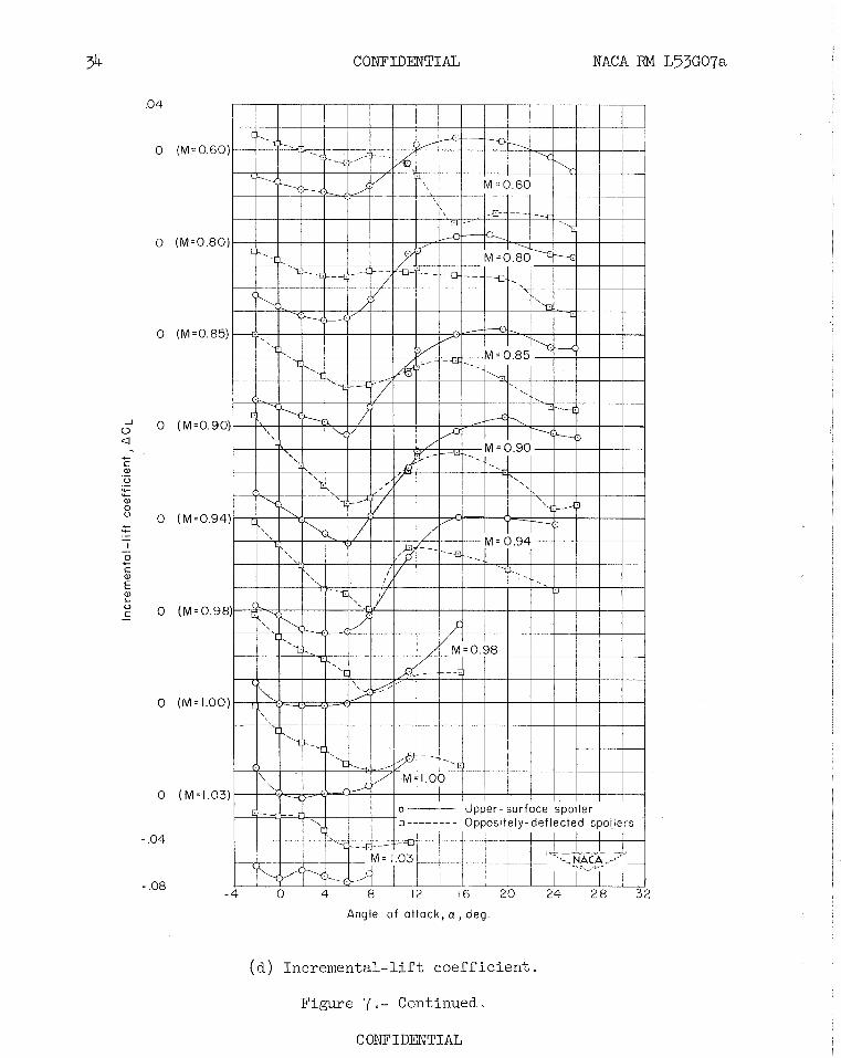
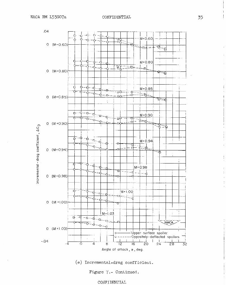
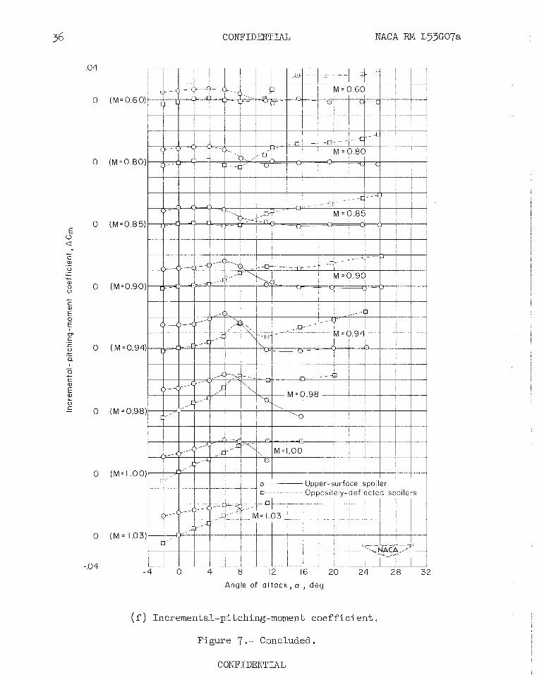
Other coefficients.- The variation of yawing-moment, lateral-force, incremental-lift, incremental-drag, and incremental-pitching-moment coef- ficient with an angle of attack (figs. 7(b), (c), (d), (e), and (f), respectively) for the oppositely deflected spoilers could have been predicted approximately from the corresponding curves for the upper- and for the lower-surface spoilers shown in figures 6(b) to 6(f) . For instance, the negligible yawing moments for the oppositely deflected spoilers up to an angle of attack of 4' would be expected from the equal and opposite yawing moments noted in figure 6(b) at the low angles of attack.
The failure of the incremental lift curve for the oppositely deflected spoilers to show no lift at an angle of p.ttack of oO, (fig. 7(d) ) is believed to be caused mainly by a difference in spoiler mounting (fig. 1) , which may have allowed some small model aerodynamic asymmetry to exist.
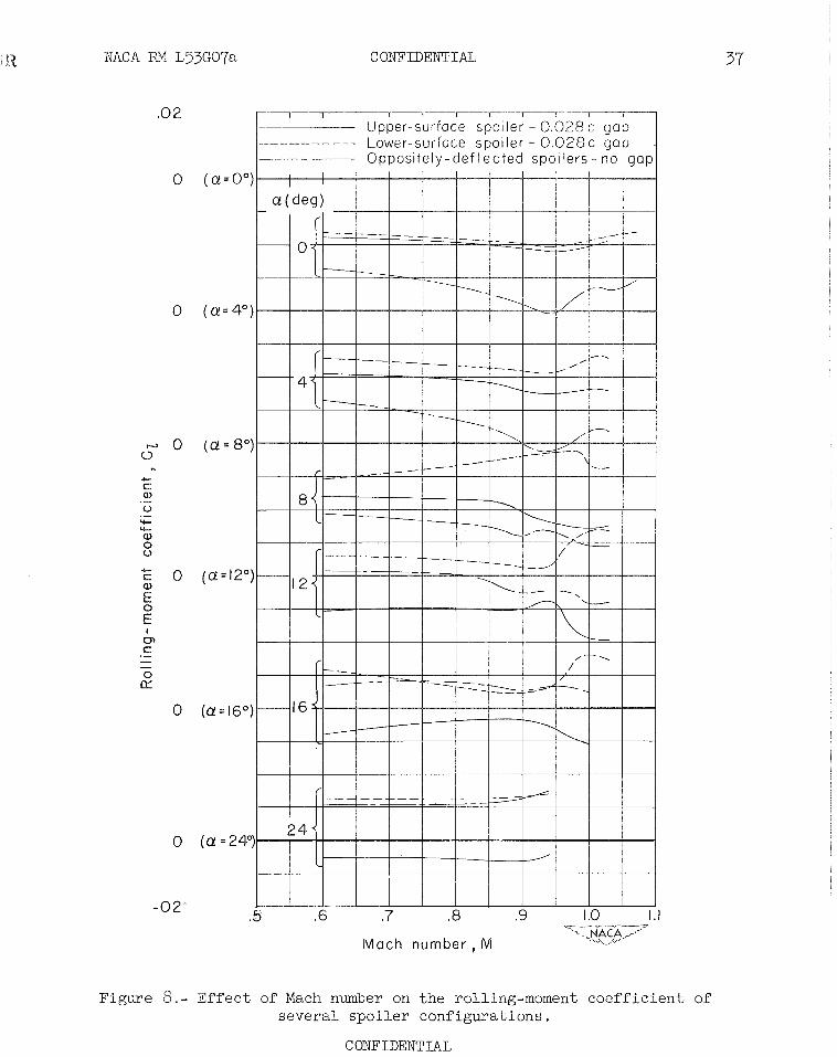
Effect of Mach Number on Spoiler Effectiveness
The variation of the rolling-moment coefficient with Mach number of several spoiler configurations is shown in figure 8. Trends with Mach number shown for the upper-surfahe spoiler configuration with 0.028-chord wing gap are representative of all the upper-surface spoiler configurations tested, although the magnitude of the rolling-moment coef- ficient may differ.
At o0 and 4' angle of attack there was a gradual increase with Mach number in the upper-surface, the lower-surface, and consequently in the oppositely deflected spoiler effectiveness that approached a maximum at a Mach number of 0.94 and then decreased slightly with further increase in Mach number. At an angle of attack of 8' the lower-surface spoiler lost effectiveness with increase in Mach number; at an angle of attack of 12' and above, the lower-surface spoiler produced a reversed rolling moment at all Mach numbers. Both these effects tended to nullify the rolling-moment effectiveness of the oppositely deflected spoiler con- figuration at the higher angles of attack. Only the upper-surface spoiler with 0.028-chord wing gap retained some effectiveness over the transonic Mach number range even at the high angles of attack. As noted in the discussion of figure ?(a), this upper-surface spoiler with 0.028-chord gap had the greatest effectiveness of any of the upper-surface spoilers with a gap.
CONFIDENTIAL NACA RM Lp3G07a
Comparison of Spoiler Effectiveness With
Aileron Effectiveness
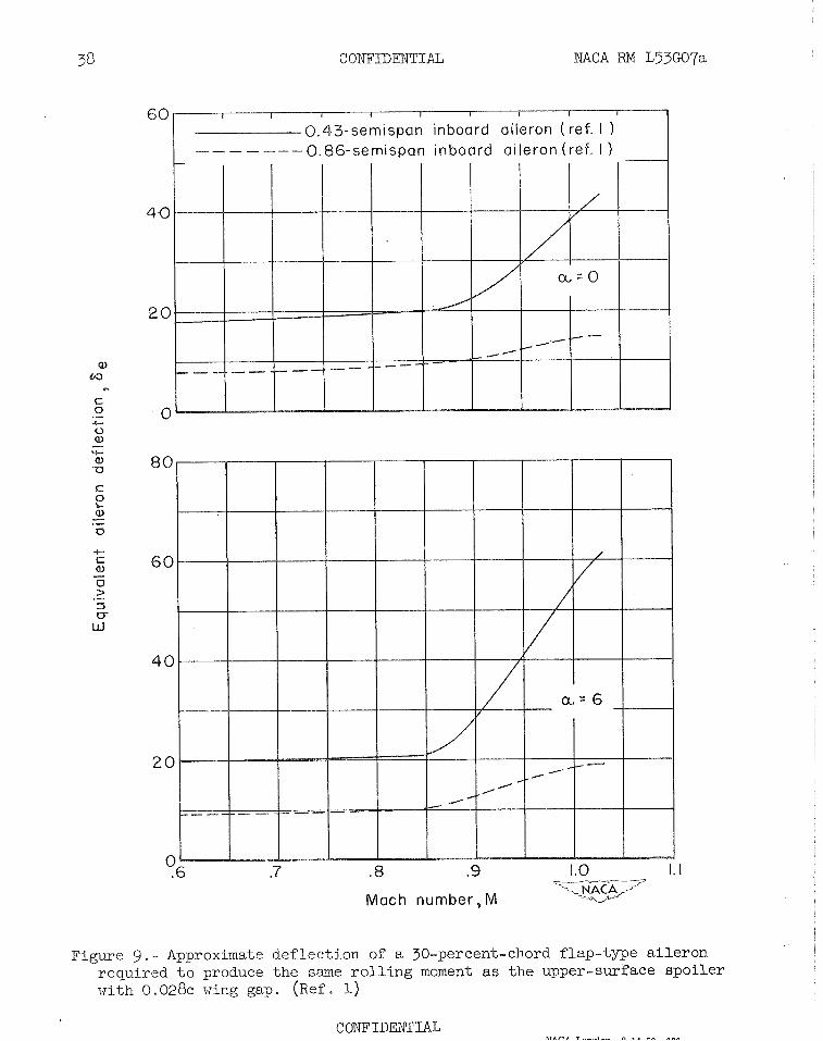
As a means of i l l u s t r a t i n g the r e l a t i v e effect iveness of the be s t spo i le r configuration reported herein, f i gu re 9 presents the approximate def lec t ion (obtained by extrapolation of t he da ta of r e f . 1) of F-percent- chord flap-type a i l e rons required t o produce the same r o l l i n g moment a s the upper-surface spo i le r with 0.028-chord wing gap. No evaluation has been made of rolling-moment requirements des i red f o r f l i g h t condit ions. These def lec t ions are f o r a i lerons located on only one wing semispan and were obtained on a reflection-plane model t h a t i s smaTler, bu t almost geometrically s imilar t o the model described i n t h i s paper ( r e f . 1) . The 0 .43-semispan and the 0.86-semispan a i l e rons extended from t h e fuse- lage t o 57 percent and 100 percent of the wing semispan, respect ively . An increase i n a i l e ron def lect ion with increase i n Mach number i s required f o r both t he a i l e ron configurations. The 0 .43-semispan inboard a i leron, i n f a c t , requires an excessive def lec t ion angle at the higher Mach numbers.
An invest igat ion was conducted with severa l 73-percent semispan inboard spo i le r a i l e rons having a height of 4 percent of t h e l o c a l wing chord and located along the 70-percent chord l i n e of a 45' sweptback wing-fuselage combination. Six-component force data were obtained a t Mach numbers from 0.60 (Reynolds number, 5 .1 x 106) t o 1.03 (Reynolds
6 number, 6.2 x 10 ) f o r an angle-of-attack range t h a t usual ly extended from -2O t o 20° o r higher. The r e s u l t s of t he invest igat ion ind ica te t he following conclusions:
1. Upper-surface-spoiler configurations with a gap i n the wing behind t he spo i l e r lose rolling-moment effect iveness above 8.n angle of a t t ack of 6' but they do r e t a i n some effect iveness even a t high angles of a t t ack f o r the e n t i r e transonic speed range, whereas t he same type of spo i le r configuration without a gap loses complete effect iveness at high angles of a t t a ck f o r most Mach numbers.
2 . Rolling-moment effectiveness of the upper-surface-spoiler con- f igura t ions increases as the lower-surface wing-gap width i s increased. A t low angles of a t t ack the influence of lower-surface wing-gap width on the rolling-moment effectiveness of t he upper-surface-spoiler con- f igura t ions decreases $n th increase i n Mach number. A t high angles of a t tack, however, l i t t l e change occurs i n the influence of the lower- surface gap width on the effectiveness with increase i n Mach number.
CONFIDENTIAL
NACA RM L53G07a CONFIDENTIAL 11
3. The lower-surface spoiler with 0.028-chord wing gap is less effec- tive at low angles of attack than the corresponding upper-surface spoiler. This lower-surf ace spoiler reverses effectiveness between angles of attack of 8O and lo0 and produces a substantial rolling moment in the reversed direction at high angles of attack.
4. For two oppositely deflected spoilers, the rolling-moment effec- tiveness at low angles of attack is much greater than for the single upper-surface spoiler, but reversal of effectiveness occurs at angles of attack above approximately 12O, where the reversed effectiveness of the lower-surfhce spoiler becomes predominant.
Langley Aeronautical Laboratory, National Advisory Committee for Aeronautics,
Langley Field, Va., July 2, 1953.
NACA RM ~ j 3 ~ 0 7 a
1. Vogler, Raymond D . : Lateral-Control Invest igat ion of Flap-Type Controls on a Wing With Quarter-Chord Line Swept Back 4 5 O , Aspect Ratio 4, Taper Ratio 0.6, and NACA 65~006 A i r f o i l Section. Transonic Bump Method. NACA RM L9F29a, 1949.
2. Hammond, Alexander D . : Lateral-Control Invest igat ion of Flap-Type and Spoiler-?Spe Controls on a Wing with Quarter-Chord-Line Sweep- back of 60°, Aspect Ratio 2, Taper Ratio 0.6, and NqCA 65~006 A i r - f o i l Section. Transonic Bump Method. NACA R14 L5OE09, 1950.
3. Ward, Vernon G., Whitcomb, Charles F., and Pearson, Merwin D . : Air-Flow and Power Character is t ics of t he Langley 16-Foot Transonic Tunnel with S lo t t ed Test Section. NACA RM L52F101, 1952.
4 . Hal l issy , Joseph M . , and Bowman, Donald R . : Transonic Charac te r i s t i cs of a 45' Sweptback Wing-Fuselage Combination. Effect of Longitudinal Wing Posi t ion and Division of Wing and Fuselage Forces and Moments. NACA RM L52.04, 1953.
5. Whitcomb, Charles F., and Osborne, Robert S . : An Experimental Inves- t i g a t i o n of Boundary Interference on Force and Moment Charac te r i s t i cs of L i f t i n g Models i n the Langley 16- and 8-Foot Transonic Tunnels. NACA RM L52L29, 1953.
6 . Hammond, Alexander D . and Watson, James M . : Lateral-Control Inves t i - gat ion a t Transonic Speeds of Retractable Spoi ler and Plug-Type Spoiler-Slot Ailerons on a Tapered 60° Sweptback Wing of Aspect Ratio 2 . NACA RM ~ 5 2 ~ 1 6 , 1952.
7. Kuhn, Richard E . : Notes on Damping i n Rol l and Load Dis t r ibut ions in Rol l a t High Angles of Attack and High Subsonic Speed. NACA RM L53G13aj 1953.
(-say
au
r ur
su
ors
ua
qp
zeau-tc TT
~)
's
uo
rq
~j
uo
~
a~
~o
ds
T
ma
na
s ayq
jo
sTT
z3a-p Tzu
orsu
amrp
pu
z Tapom
a
Bz
~a
sn
j-Bu
~x
ay
? jo
ure
Bz
ra --I ax
G3
-t~
CONFIDENTIAL
NACA RM L53G07a COWIDENTLAL 15
Angle of a t tack , CY. , deg.
Figure 3.- Average base-pressure coefficient for all configurations.
NACA RN Lf53G07a CONFIDENTIAL
(b) Drag coefficient . Figure 4.- Continued.
18 CONFIDE2iTIAL NACA RM L53GO7a
Angle of a t tack , a , deg
(c) Pitching-moment coefficient.
Figure 4.- Concluded.
- ,-.m--.-n-Tm-r A 7
- 4 0 4 8 12 16 2 0 24 28 32
Angle of attack, a , deg.
(a) Rolling-moment coefficient.
Figure 5.- Comparison of the aerodynamic characteristics of several upper- surface spoiler configurations showing the effect of variations in the width of the wing gap behind the spoilers. Spoilers on left wing.
Angle o f a t t a ck , o! , deg
(b) Yawing-moment coefficient.
Figure 5.- Continued. r* r \ x m r nrm'rm-r .4 T
NACA RM L53G07a COESFIDFSJTLAI,
Angle of a t t a ck , a , deg
(c) Side-force coefficient.
Figure 5.- Continued.
CONFIDENTIAL
CONFIBmIA&I NACA RM L53G07a
Angle of at tack , a , deg.
(d) Incremental-Lift coefficient . Figure 5.- Continued.
CONFIDENTIAL
CONFIDENTIAL
Angle o f a t tack , a , deg
(e) Incremental-drag coefficient . Figure 5.- Continued.
CONFIDENTIAL
Angle of a t t a c k , a , deg
(f ) Incremental-pitching-moment coefficient . Figure 5,- Concluded.
n r \ l \mTnmTmT R T
NACA HM L53G07a CONFIDENTIAE
Angle o f attack, a , deg.
(a) Rolling-moment coefficient.
Figure 6.- Comparison of the aerodynamic characteristics of an upper- surface spoiler on left wing with a lower-surface spoiler on right wing. 0.028~ wing gap.
C ONFIDENTIAL
C O N F I D ~ I A L NACA RM L53G07a
(b) Yawing-moment coefficient . Figure 6.- Continued.
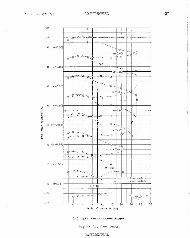
NACA RM L53G07a COJD'IDED'I'IAL
Angle of a t tack , a , deg.
(c) Side-force coefficient.
Figure 6.- Continued.
CONFIDEWI'IAL
CONFIDE2NTIAL NACA RM L53G07a
Angle of attack , a , d e g
(d) Incremental-lift coefficient . Figure 6.- Continued.
CONFIDESSTIAL
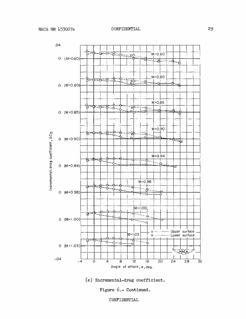
NACA RM L53G07a CONFIDENTIAL 29
( e ) Incremental-drag coefficient . Figure 6. - Continued.
COXFIDENTIAL
CONFIDEXTI'IAL NACA RM L53G07a
Angle of a t t ack , a , deg.
( f ) Increnental-pitching-moment coefficient . Figure 6 .- Concluded.
NACA RM L53G07a CONFIDENTIAL
(a) Rolling-moment coefficient.
Figure 7.- Comparison of the aerodynamic characteristics of an upper- surface spoiler with oppositely deflected spoilers. No wing gap.
CONFIDENTIAL
32 CONFIDmIAL NACA RM L53G07a
Angle of attack, a! , deg.
(b ) Yawing-moment coefficient . Figure 7.- Continued.
C ONFIDENT IAL
NACA RM L53G07a CONFIDENTIAL
(M = 0.60)
(M = 0.80)
(M = 0.85)
(M = 0.90)
(M = 0.94)
(M ~0.98)
(M = 1.00)
(M = 1.03)
- 4 0 4 8 12 16 20 24 28 32
Angle of attack ,a, deg.
(c) Side-force coefficient.
Figure 7.- Continued.
C om IDENTIAL
34 COWIDENTIAL NACA RM L53G07a
Angle o f at tack, a , deg
(d) Incremental-lift coefficient . Figure 7.- Continued.
CONFIDENTIAL
NACA RM L5307a C O N F ' I D W I A L
Angle of a t tack , a ! , deg
(e) Incremental-drag coefficient . Figure 7. - Continued-.
COlJFIDENTIAL
36 CONFIDENTIAL NACA RM L53G07a
Angle of o t t o c k , a , d e g
(f ) Incremental-pitching-moment coefficient . Figure 7 .- Concluded.
CONFIDENTIAL
NACA RM L53GO7a CONFTDENTIAL
Mach number , M
Figure 8.- Effect of Mach number on the rolling-moment coefficient of several spoiler configurations.
CONFIDENTIAL
60 1 I I I I
0.43-semispan - - - - - - - 0.86-semispan inboard ai leron (ref. I )
Figure 9.- Approximate def lect ion of a 30-percent-chord flap-type a i l e ron required t o produce the same r o l l i n g moment a s t he upper-surface spo i le r with 0 . 0 2 8 ~ wing gap. ( ~ e f . 1)
CONFIDENTIAL
I N F O R W
I DENTlAL
'-a e '
' * II w- - s
CON
Restriction/Classification Cancelled
Restriction/Classification Cancelled