Embed Size (px)
Citation preview

Switches and Circuit Protection 4-5
ELECTRIC
S
of a thermal element when the latter has been carrying a designed current for a pre-determined period.
The diagram of a motor driven time switch unit is shown in fig. El 4.9. It is designed to actuate relays which, in turn, control the supply of alternating current to the heating elements of a power unit de-icing system.
Signals to the relays are given in repeated time cycles which can be of short or long duration corresponding respectively to ‘fast’ and ‘slow’ selections made on the appropriate system control switch.
4.1.9 Pressure SwitchesIn many of the aircraft systems in which pressure measurement is involved, it is necessary that a warning is given of either high or low pressures which might constitute hazardous operating conditions. In some systems also, the frequency of operation may be such that the use of a pressure measuring instrument is not justified since it is only necessary for some indication that an operating pressure has been attained for the period during which the system is in operation. To meet this requirement, pressure switches are installed
Spring (long member)
Operating plunger
Fixed contact(normally closed)
Fixed contact(normally open)
Common terminal
Side members
Sealed housing
Roller Roller guidelock ring
LockwasherTab washer
Body
Cable
Steel cap
Bushingkeyway
Lockingwire hole
Bushing Plungeractuator
Fig. EL 4.8 Micro switches
Fig. EL 4.9 Time switch (older type)
High speedgear assembly
Intermediategear assembly
Camshaft assembly
Micro-switches
Centrifugal switch
Motor
Electrics E5 - Final.indb 5 11.04.2008 10:55:13

4-6 Switches and Circuit Protection
ELECTRIC
S
and are connected to warning lights located on the cockpit panels.
A typical switch, as shown in fig. EL 4.10, consists of a metal diaphragm bolted between the flanges of the two sections of the switch body. A chamber is formed on one side of the diaphragm and is open to the pressure source. On the other side of the diaphragm a push rod, working through a sealed guide, bears against contacts fitted in a terminal block, connected to the warning or indicator light assembly. The contacts may be arranged to ‘make’ on either decreasing or increasing pressure, and their gap settings may be pre-adjusted in accordance with the pressures at which warning is required.
Pressure switches may also be applied to systems requiring that warning is given of changes in pressure with respect to a certain datum pressure; in other words, as
a differential pressure warning device. The construction and operation are basically the same as the standard type, with the exception that the diaphragm is subjected to a pressure on each side.
4.1.10 Thermal SwitchesThermal switches are applied to systems in which a visual warning of excessive temperature conditions is required. They are also used where automatic temperature control and automatic operation of protection devices are required.
Examples of such applications are overheating of a generator, control of valves in a thermal de-icing system and the automatic operation of fire extinguishers.
A common type employs a strip of two different metals clamped or riveted together. The metals are chosen (usually invar and steel, invar is an alloy of nickel and steel) to have very different coefficients of expansion so that the metal strip will bend with rise in temperature. As it bends it moves two contacts together to make a circuit and activate the warning light or relay. The strip straightens, when temps drop, and opens the contacts. A different type is shown in fig. EL 4.11. The heat-sensitive element is an alloy steel barrel containing a spring bow assembly of low coefficient of expansion. Each limb of the bow carries a silver-rhodium contact connected by fire-resistant cable to a terminal block located within a steel case.
In the event of a fire or sufficient rise in temperature at the switch location the barrel
+
No Light
Light
+
Fig. EL 4.10 Pressure switch
High pressure
Low pressure
Membrane
Spring
Spring
Membrane
Electrics E5 - Final.indb 6 11.04.2008 10:55:13
Switches and Circuit Protection 4-7
ELECTRIC
S
will expand and remove the compressive force from the bow assembly, permitting the contacts to close the circuit to its relevant warning light. When the temperature drops, the barrel contracts, thus compressing the bow assembly and re-opening the contacts.
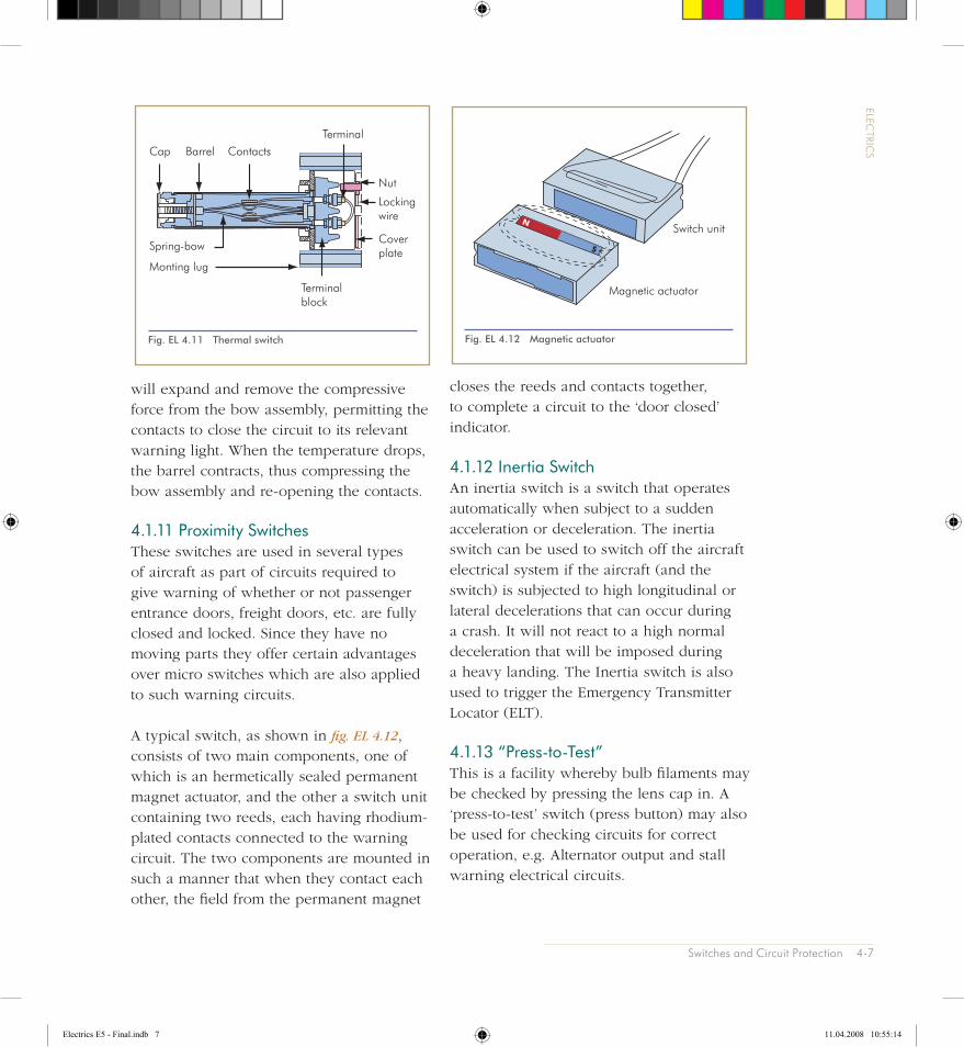
4.1.11 Proximity Switches These switches are used in several types of aircraft as part of circuits required to give warning of whether or not passenger entrance doors, freight doors, etc. are fully closed and locked. Since they have no moving parts they offer certain advantages over micro switches which are also applied to such warning circuits.
A typical switch, as shown in fig. EL 4.12, consists of two main components, one of which is an hermetically sealed permanent magnet actuator, and the other a switch unit containing two reeds, each having rhodium-plated contacts connected to the warning circuit. The two components are mounted in such a manner that when they contact each other, the field from the permanent magnet
closes the reeds and contacts together, to complete a circuit to the ‘door closed’ indicator.
4.1.12 Inertia SwitchAn inertia switch is a switch that operates automatically when subject to a sudden acceleration or deceleration. The inertia switch can be used to switch off the aircraft electrical system if the aircraft (and the switch) is subjected to high longitudinal or lateral decelerations that can occur during a crash. It will not react to a high normal deceleration that will be imposed during a heavy landing. The Inertia switch is also used to trigger the Emergency Transmitter Locator (ELT).
4.1.13 “Press-to-Test”This is a facility whereby bulb filaments may be checked by pressing the lens cap in. A ‘press-to-test’ switch (press button) may also be used for checking circuits for correct operation, e.g. Alternator output and stall warning electrical circuits.
Fig. EL 4.11 Thermal switch
Cap BarrelTerminal
Contacts
Spring-bow
Monting lug
Terminal block
Coverplate
Lockingwire
Nut
Fig. EL 4.12 Magnetic actuator
N
S
Switch unit
Magnetic actuator
Electrics E5 - Final.indb 7 11.04.2008 10:55:14

4-8 Switches and Circuit Protection
ELECTRIC
S
4.1.14 RelaysRelays, fig. EL 4.13, are electromagnetic switching devices by means of which one electrical circuit can be indirectly controlled by a change in the same or another electrical circuit.
Various types of relay are in use, their construction, operation, power ratings, etc., being governed by their applications, which are also varied and numerous. In its basic form, a relay may be considered as being made up of two principal elements, one for operating the relay mechanism, and the other for controlling the changes.
The sensing and operating element is an electromagnetic coil and armature, and the controlling element is one or more pairs of contacts.
As in the case of switches, relays are also designated by their ‘pole’ and ‘throw’ arrangements and these can range from the simple ‘single-pole, single throw’ type to complex multiple contact assemblies, controlling a variety of circuits and operated by the one relay.
4.1.15 SolenoidsSolenoids (sometimes called contactors) provide a short linear movement that may be used to close or open switch contacts, e.g. a starter solenoid or valves, see fig. EL 4.14.
Current through the coil will create a magnetic field, like a bar magnet, that will magnetise the movable soft iron core to have an opposite polarity to the coil field and, because unlike poles attract, the core will be pulled inside the coil against the spring force, as shown in fig. EL 4.15. The mechanical linkage can be attached to contacts which close when the coil is energised e.g. starter motor ON. When the coil is de-energised the magnetic field collapses and the spring opens the contacts.
In many applications the relay (or solenoid) is energised directly from the aircraft supply, while in others it may be energised by signals from an automatic device such as an amplifier in a cabin temperature-control system, or a fire detector unit. When the relay coil is energised, a magnetic field is
Fig. EL 4.13 Relay
Moving contact
Ceramic cap
Core head
Contact spring
Braid
Armature
Pivot pin
YokeStop
Fixed contact
Bracket
Insulatingblock
Soldertag
Coil
Restoring spring
Terminal bracket
Electrics E5 - Final.indb 8 11.04.2008 10:55:14

Switches and Circuit Protection 4-9
ELECTRIC
S
set up and at a pre-determined voltage level (called the ‘pull-in voltage’) the armature is attracted to a pole piece against spring restraint, and actuates the contact assembly, this in turn either completing or interrupting the circuit being controlled. When the relay coil circuit is de-energised the spring returns the armature and contact assembly to the inoperative condition. The voltage at which the spring leaves the pole piece is known as the ‘drop-out voltage’.
4.1.16 Polarized Armature RelaysIn certain specialised applications, the value of control circuit currents and voltages may be only a few milliamps and millivolts, and therefore relays of exceptional sensitivity are required. This requirement cannot always be met by relays which employ spring-controlled armatures, for although loading may be decreased to permit operation at a lower ‘pull-in’ voltage, effective control of
Fig. EL 4.14 Solenoid switch
Coil assembly
Terminalmoulding
Coilterminals
Spindle andcollar assembly
Contact plate
Main contact
Mainterminals
Returnspring
Fig. EL 4.15 Solenoid principle
Soft ironcore
Coil
Spring
Solenoidde-energised
Magnetic field due tocurrent through coil
Core becomesmagnetised
Solenoidenergised
Electrics E5 - Final.indb 9 11.04.2008 10:55:14

4-10 Switches and Circuit Protection
ELECTRIC
S
the contacts is decreased and there is a risk of contact flutter. A practical solution to this problem resulted in a relay in which the attraction and repulsion effects of magnetic forces are substituted for the conventional spring-control of the armature and contact assembly.
The armature is a permanent magnet and is pivoted between two sets of pole faces formed by a frame of high permeability material, usually µ-metal. (µ-metal is an alloy, consisting mainly of nickel and iron, which has extremely high magnetic permeability at low field strengths). See fig.
EL 4.16. It is lightly biased to one side to bring the contact assembly into the static condition as in (a). The centre limb of the frame carries a low inductance low current winding which exerts a small magnetising
force on the frame when it is energised from a suitable source of direct current. With the armature in the static condition, the frame pole faces acquire, by induction from the armature, the polarities shown, and the resulting forces of magnetic attraction retain the armature firmly in position.
When a DC voltage is applied to the coil the frame becomes, in effect, the core of an electromagnet. The flux established in the core opposes and exceeds the flux due to the permanent magnet armature, and the frame pole-faces acquire the polarities shown in (b). As the armature poles and frame pole-faces are now of like polarity, the armature is driven to the position shown in (c) by the forces of repulsion. In this position it will be noted that poles and pole-faces are now of unlike polarity, and strong
Fig. EL 4.16 Polarized armature relay
Frame
DC
Armature
Electrics E5 - Final.indb 10 11.04.2008 10:55:14

Switches and Circuit Protection 4-11
ELECTRIC
S
forces of attraction hold the armature and contact assembly in the operating position.
The flux derived from the coil and the armature act in the same direction to give a flux distribution as shown in (c). When the coil circuit supply is interrupted, the permanent magnet flux remains, but the force due to it is weaker then the armature bias force and so the armature and contacts are returned to the static condition.
4.2 Circuit Protection DevicesIn the event of a short circuit, an overload or other fault condition occurring in the circuit formed by cables and components of an electrical system, it is possible for extensive damage and failure to result. For example, if the excessive current flow caused by a short circuit at some section of a cable is left unchecked, the heat generated in the cable will continue to increase until something gives way. It is essential therefore to provide devices in the network of the power distribution to systems, and having the common task of protecting their circuits, cables and components.
The devices normally employed are fuses, circuit breakers and current limiters. In some cases, there may be unprotected circuits, e.g. the main starter circuit.
4.2.1 FusesA fuse is a thermal device designed primarily to protect the cables and components of a circuit against the flow of short-circuit and overload currents. In its basic form, a fuse consists of a low melting
point fusible element or link, enclosed in a glass or ceramic casing which not only protects the element, but also localises any flash which may occur when ‘fusing’. The element is joined to end caps on the casing, the caps in turn, providing the connection of the element with the circuit it is designed to protect, see fig EL 4.17.
Under short-circuit or overload current conditions, heating occurs, but before this can affect the circuit cables or other elements, the fusible element, which has a much lower current-carrying capacity, melts and interrupts the circuit. The materials most commonly used for the elements are tin, lead, alloy of tin and bismuth, silver or copper in either the pure or alloyed state.
The construction and current ratings of fuses vary, to permit a suitable choice for specific electrical installations and proper protection of individual circuits. Fuses are, in general, selected on the basis of the lowest rating consistent with reliable system operation, thermal characteristics of cables, and without ‘nuisance tripping’. The rating is given in amperes, and indicates how much current it will carry before rupturing.
For emergency circuits, i.e. circuits the failure of which may result in the inability of an aircraft to maintain controlled flight and effect a safe landing, fuses are of the highest rating possible consistent with cable protection.
Fuses are also influenced by ambient temperature variations. These can affect to some extend the minimum ‘blowing’
Electrics E5 - Final.indb 11 11.04.2008 10:55:14

4-12 Switches and Circuit Protection
ELECTRIC
S
current, as well as ‘blowing’ time at higher currents. The heavy duty or rupturing capacity fuse is designed for installation at main power distribution points. It consists
of a ceramic barrel with sand because of the high temperatures involved.
4.2.2 Current LimitersCurrent limiters are designed to limit the current to some pre-determined ampere value. They are also thermal devices, but unlike ordinary fuses they have a high melting point, so that their time/current characteristics permit them to carry a considerable overload current before rupturing, see fig EL 4.18.
Their application is confined to the protection of heavy-duty power distribution circuits. A typical current limiter incorporates a fusible element, which is in effect a single strip of tinned copper, drilled and shaped at each end to form lug type connections, with the central portion ‘waisted’ to the required width to form the fusing area. The central portion is enclosed by a rectangular ceramic housing, one side of which is furnished with an inspection window which, depending on the type, may be of glass or mica.
Fig. EL 4.17 Symbols and fusetypes
A light duty circuit fuse
Fuse symbols
A high rapturing capacity fuse
Terminals
Fuse cartridge
Terminals
Fusible element
Fig. EL 4.18 A typical current limiter (an airfuse)
Electrics E5 - Final.indb 12 11.04.2008 10:55:14

Switches and Circuit Protection 4-13
ELECTRIC
S
They are a combined fuse and switch device. Circuit breakers are used for the protection of cables and components and can be restored after clearance of a fault. In this way, they avoid some of the replacement problems associated with fuses and current limiters.
In general, they consist of a bi-metallic thermal element, a contact type switch unit and a mechanical latching mechanism. A push-pull button is also provided for manual resetting after thermal tripping has occurred, and for manual tripping when it is required to switch off the supply to the circuit of a system. The button may have a white band that is exposed when the CB trips. This makes it very easy for the pilot to see the tripped CB among numerous other CBs.
Pressing the re-set button will reset either circuit breaker if the fault has been cleared. CBs for essential services should be reset once only, if there are no clearly associated conditions of smoke or fumes. CBs for non-essential and domestic services that are in passenger areas, should not be reset.
Trip-Free/Nontrip-Free Circuit BreakersCircuit breakers are classified as being ‘trip free’ or ‘nontrip free’.
A trip-free circuit breaker is a circuit breaker that will trip (open) even if the operating mechanism (ON-OFF switch) is held in the ON position.
A nontrip-free circuit breaker can be reset and/or held ON even if an overload or excessive heat condition is present. In
4.2.3 Circuit Breakers Circuit breakers or CBs, unlike fuses or current limiters, isolate faulted circuits and equipment by means of a mechanical trip device actuated by the heating of a bimetallic element through which the current passes to a switch unit, see fig EL 4.19.
Fig. EL 4.19 Circuit breakers, tripped and reset
Terminals Mountingnut
Shakeproofwasher
Housing Pushpullbutton
Whitemarker band,tripped
Reset
Tripped
Reset
Electrics E5 - Final.indb 13 11.04.2008 10:55:15

4-14 Switches and Circuit Protection
ELECTRIC
S
other words, a nontrip-free circuit breaker can be bypassed by holding the operating mechanism ON. This is clearly dangerous.
Trip-free circuit breakers are used on circuits that cannot tolerate overloads and on non-emergency circuits. Examples of these are precision or current sensitive circuits, non-emergency lighting circuits, and nonessential equipment circuits.
Nontrip-free circuit breakers are used for circuits that are essential for operations. Examples of these circuits are emergency lighting, required control circuits, and essential equipment circuits.
Circuit breakers are the most common overload protection devices used in aircraft and the most commonly used type is the push and pull type
4.2.4 Reverse Current Circuit BreakersThese circuit breakers are designed to protect power supply systems and associated circuits against fault currents reversing against the normal current direction of flow of a magnitude greater than those at which cut-outs normally operate.They are designed to remain in a ‘locked-out’ condition to ensure complete isolation of a circuit until a fault has been cleared.
4.2.5 Magnetic Circuit BreakersA magnetic circuit breaker is a quick tripping response protective system.
Electrics E5 - Final.indb 14 11.04.2008 10:55:15

Switches and Circuit Protection 4-15
ELECTRIC
SQUESTIONS
1 In order to avoid accidental operation of a toggle switch, another type of switch can be used, namely a:
a) Push-switchb) Time switchc) Rotary switchd) Pressure switch
2 Which of the following switches is most extensively used in aircraft ?:
a) Thermal switchb) Time switchc) Micro switchd) Pressure switch
3 The main difference between a fuse and a circuit breaker is that:
a) The fuse can be reset after having been tripped, the circuit breaker can not
b) The fuse has to be replaced, but the circuit breaker can be resetc) The circuit breaker is used to protect inductive loads, while the fuse is
used to protect resistive loads, otherwise no differenced) The circuit breaker is used for high loads, while the fuse is used for
small, electronic loads
4 Fuses are rated to a value by:
a) The number of volts they will passb) The number of amperes they will normally rupture atc) Their wattaged) Their resistance measured in ohms
Electrics E5 - Final.indb 15 11.04.2008 10:55:15

4-16 Switches and Circuit Protection
ELECTRIC
S
5 A current limiting fuse:
a) Would be used to prevent overinfaltion of the tyresb) Will carry a considerable overload before rupturingc) Ruptures immediately when current reaches a preset valued) Prevents generator overload
6 A thermal circuit breaker works on the principle of:
a) Differential expansion rates of different metalsb) Differential density of different metalsc) Differential ductility of different metalsd) Increased resistance with temperature
7 The most common overload protection device used in large transport aircraft is:
a) Circuit breakersb) Fusesc) Blow torchesd) Relays
8 What is the difference between a relay and a solenoid?
a) The solenoid is automatically operated while the relay is manually operatedb) The relay does not have a movable corec) Relays are only used within DC electricity while solenoids within AC electricityd) Relays are used in high voltage circuits while solenoids in low voltage circuits
Electrics E5 - Final.indb 16 11.04.2008 10:55:15

Switches and Circuit Protection 4-17
ELECTRIC
S
9 A trip-free circuit breaker is one which:
a) Cannot be reset whilst the fault persistsb) Can be re-made whilst the fault persistsc) Must be held in during circuit testingd) Can only be reset by an engineer
10 Which circuit in an aircraft electrical system is not required to be protected by a circuit protection device?
a) The main starter circuitb) The battery circuitc) The main bus circuitd) The hot bus circuit
The answers can be found at the end of the book
Electrics E5 - Final.indb 17 11.04.2008 10:55:15

Intentionally blank
Electrics E5 - Final.indb 18 11.04.2008 10:55:15