Embed Size (px)
Citation preview
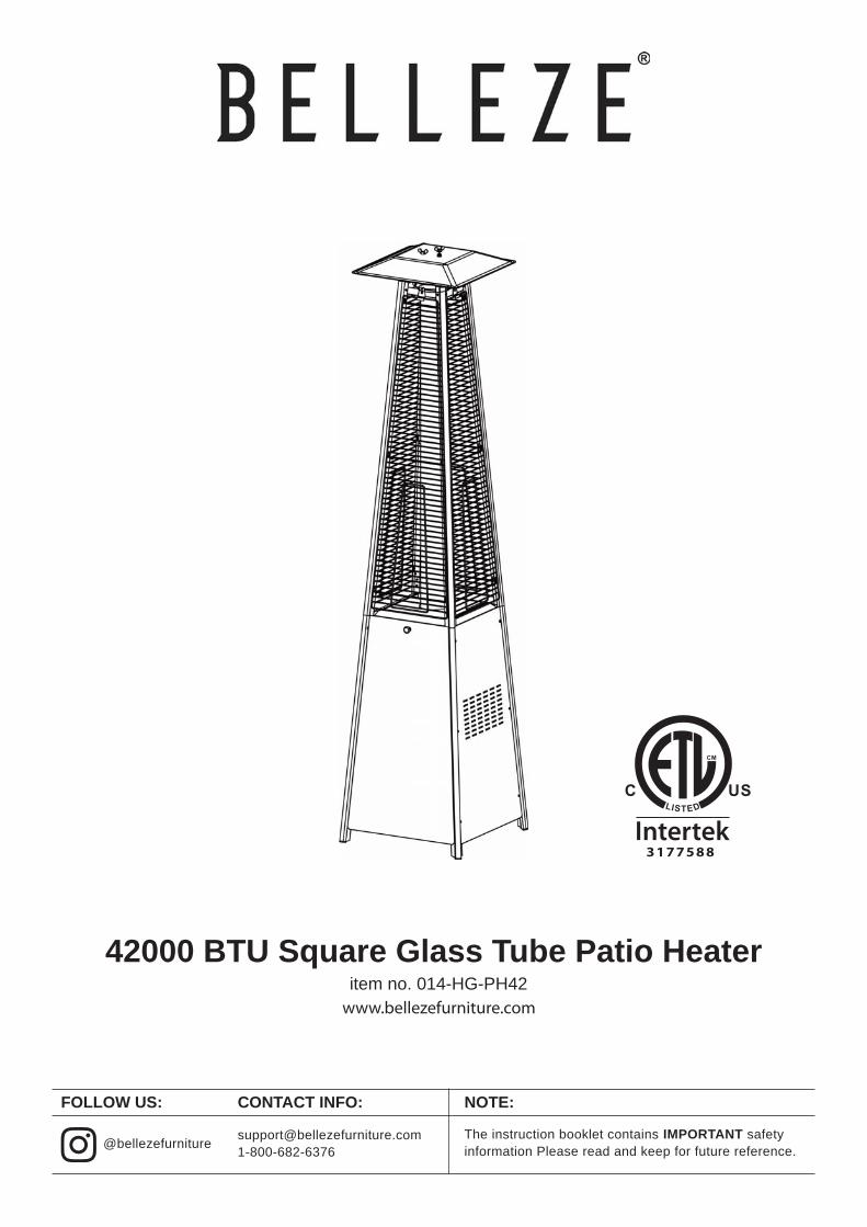
42000 BTU Square Glass Tube Patio Heateritem no. 014-HG-PH42www.bellezefurniture.com
[email protected]@bellezefurniture
FOLLOW US: CONTACT INFO: NOTE:
The instruction booklet contains IMPORTANT safety information Please read and keep for future reference.
OUR BRAND
PLEASE LIKE, COMMENT AND FOLLOW.
TABLE OF CONTENTS
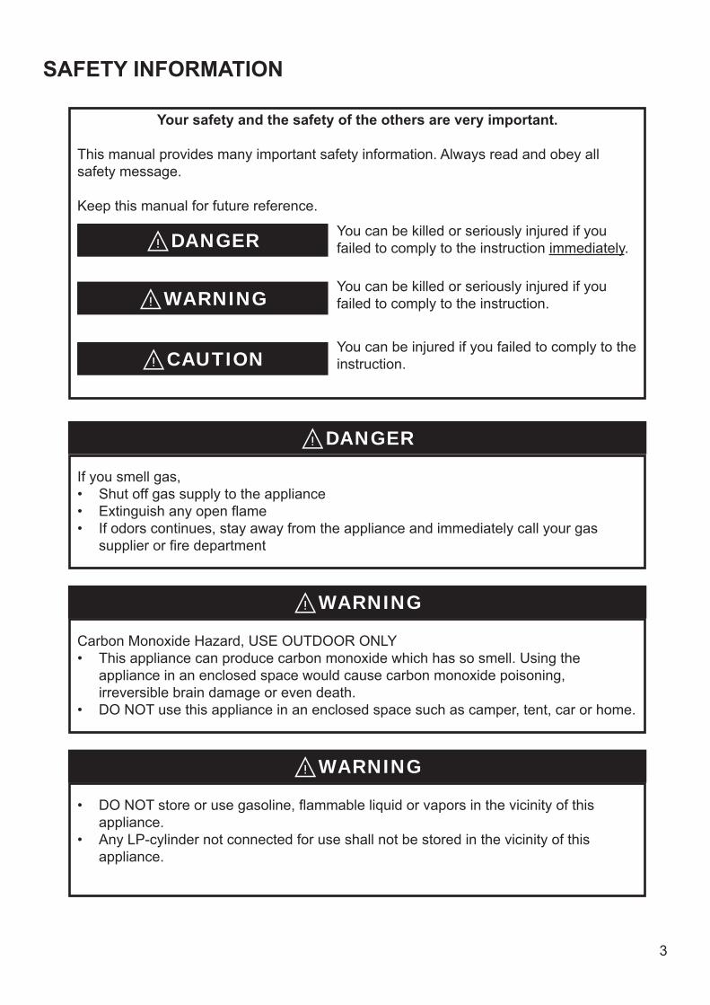
SAFETY INFORMATION
Your safety and the safety of the others are very important.
DANGER
DANGER
WARNING
WARNING
WARNING
CAUTION
4
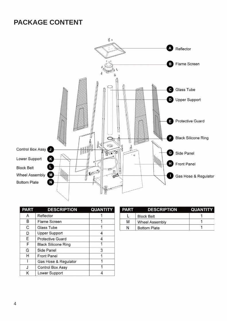
PACKAGE CONTENT
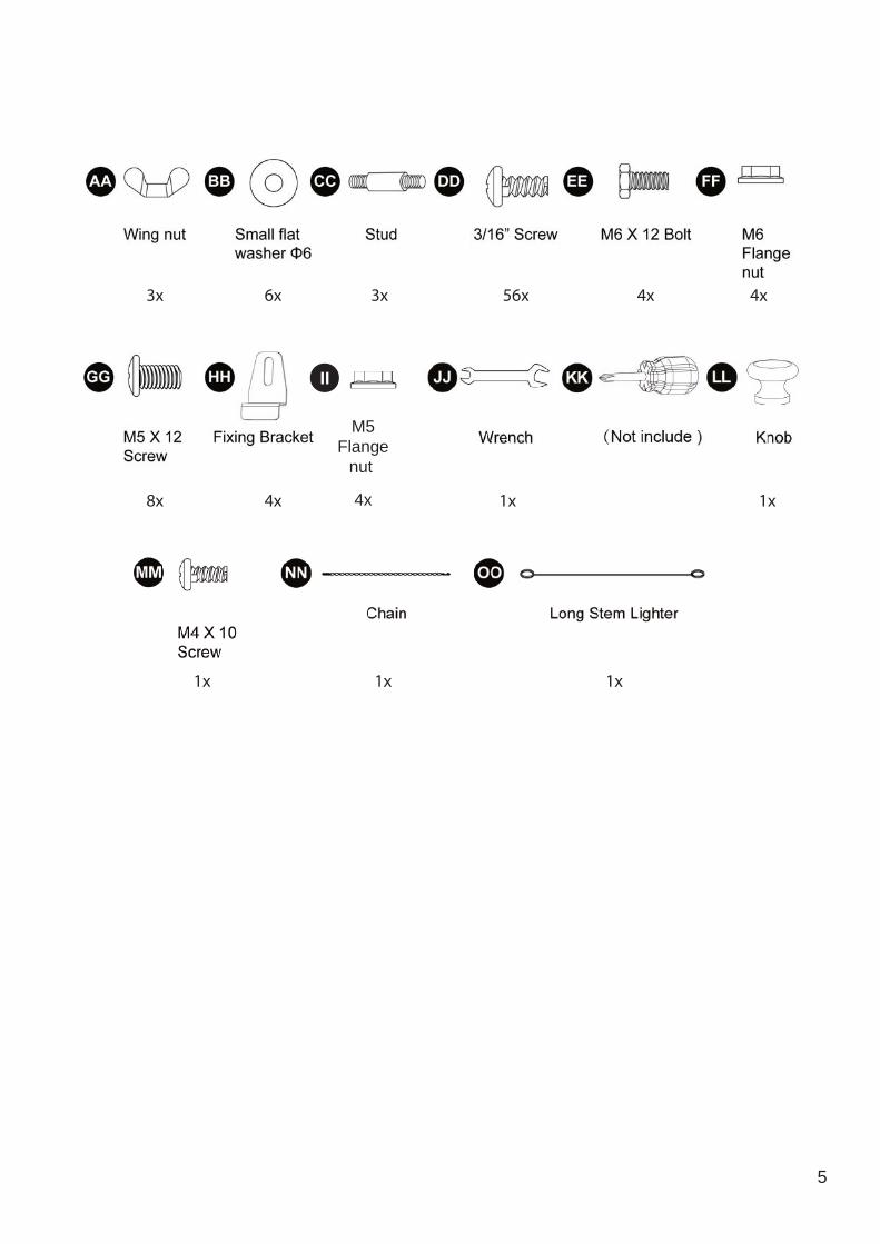
5
3x
8x
1x
6x
4x
3x
1x
56x
1x
4x
1x
4x
1x
(Not include )
1x
II
M5Flange
nut
4x
6
ASSEMBLY INSTRUCTION
Estimated Time for Assembly
60:00
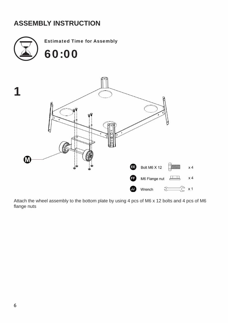
1
Attach the wheel assembly to the bottom plate by using 4 pcs of M6 x 12 bolts and 4 pcs of M6 flange nuts
7
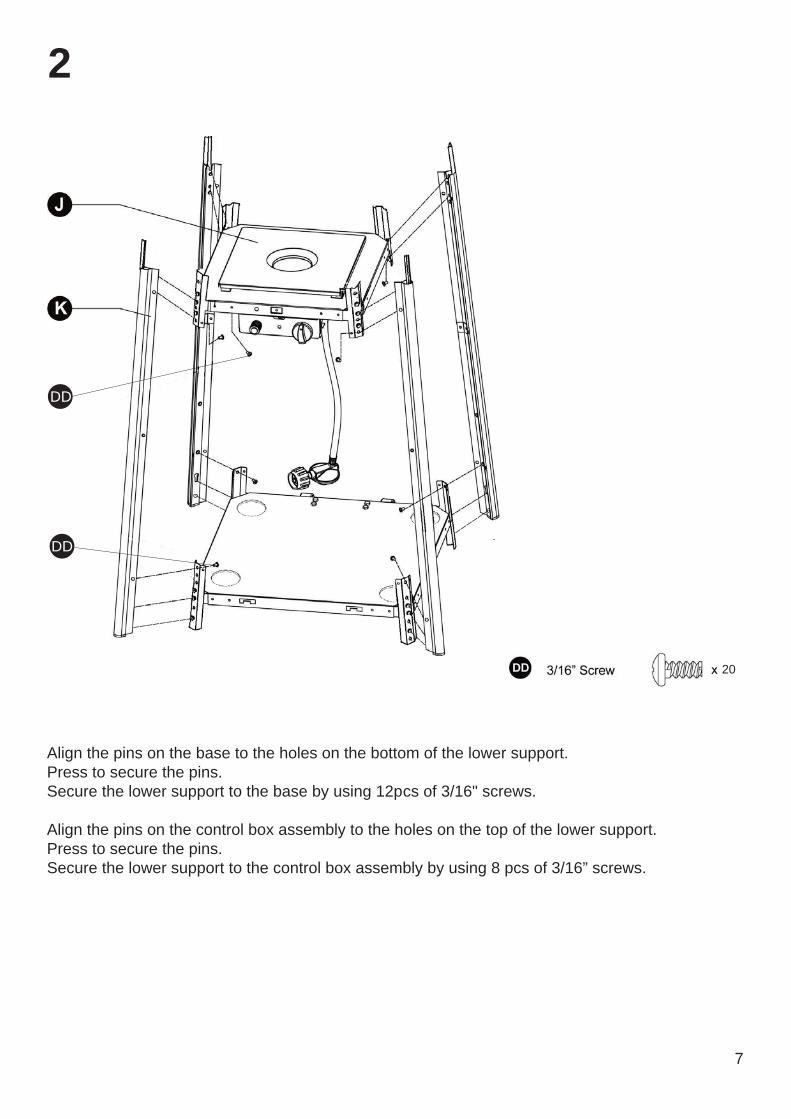
2
Align the pins on the base to the holes on the bottom of the lower support.Press to secure the pins.Secure the lower support to the base by using 12pcs of 3/16" screws.
Align the pins on the control box assembly to the holes on the top of the lower support.Press to secure the pins.Secure the lower support to the control box assembly by using 8 pcs of 3/16” screws.
20
DD
DD
DD
8
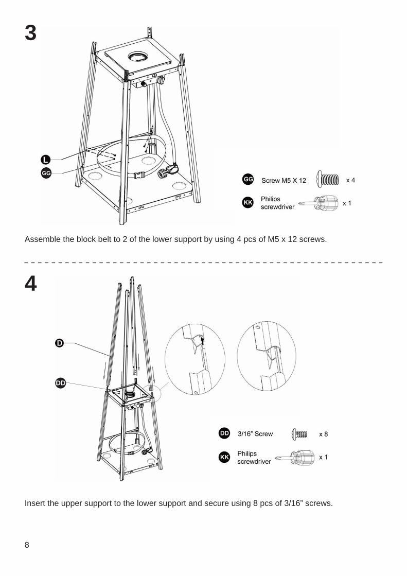
3
4
Assemble the block belt to 2 of the lower support by using 4 pcs of M5 x 12 screws.
Insert the upper support to the lower support and secure using 8 pcs of 3/16” screws.
GG4
9
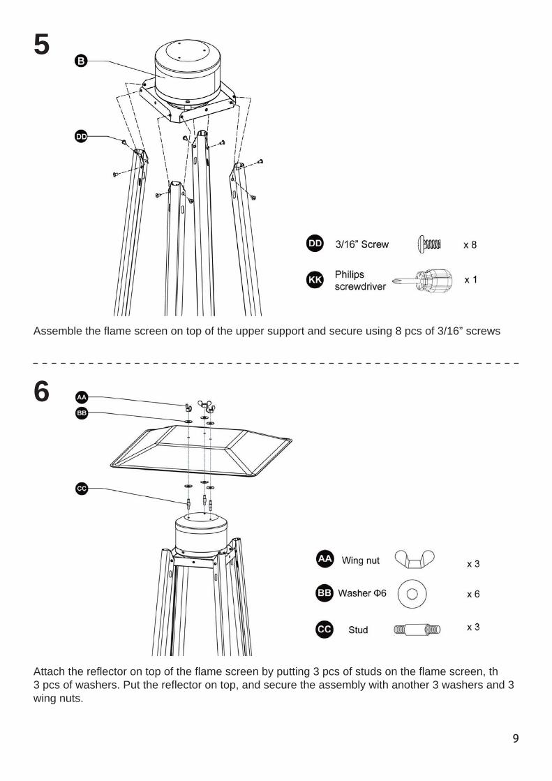
6
5
Assemble the flame screen on top of the upper support and secure using 8 pcs of 3/16” screws
Attach the reflector on top of the flame screen by putting 3 pcs of studs on the flame screen, th3 pcs of washers. Put the reflector on top, and secure the assembly with another 3 washers and 3wing nuts.
10
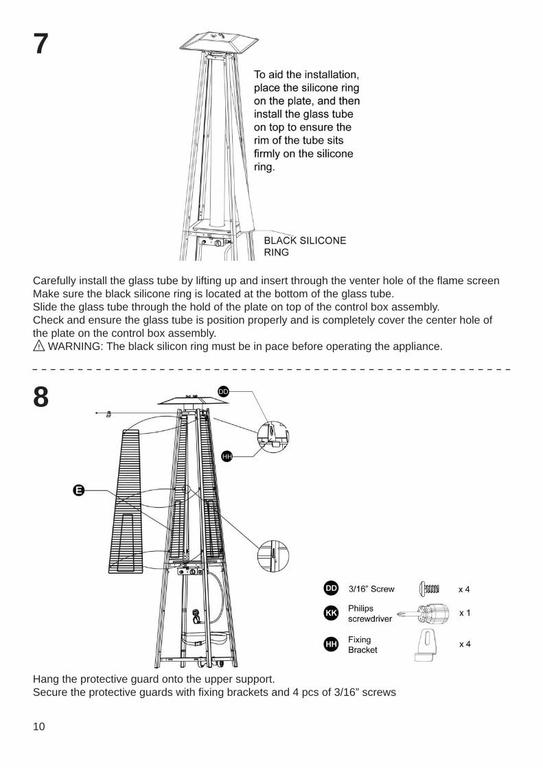
7
Carefully install the glass tube by lifting up and insert through the venter hole of the flame screenMake sure the black silicone ring is located at the bottom of the glass tube.Slide the glass tube through the hold of the plate on top of the control box assembly.Check and ensure the glass tube is position properly and is completely cover the center hole of the plate on the control box assembly.
WARNING: The black silicon ring must be in pace before operating the appliance.
Hang the protective guard onto the upper support.Secure the protective guards with fixing brackets and 4 pcs of 3/16” screws
8 DD
HH
11
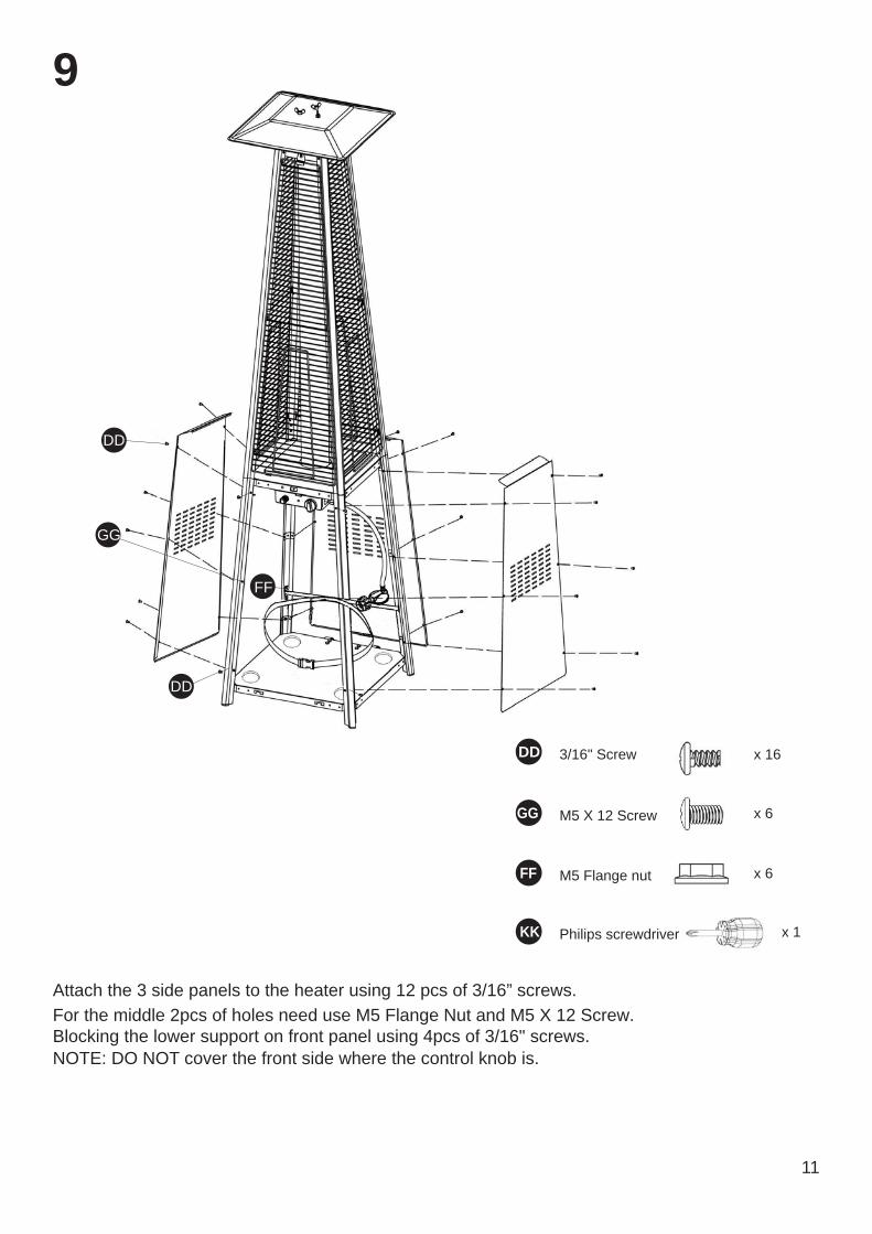
9
Attach the 3 side panels to the heater using 12 pcs of 3/16” screws.
NOTE: DO NOT cover the front side where the control knob is.
For the middle 2pcs of holes need use M5 Flange Nut and M5 X 12 Screw.Blocking the lower support on front panel using 4pcs of 3/16" screws.
DD
GG
FF
GG x 6M5 X 12 Screw
FF x 6M5 Flange nut
KK x 1Philips screwdriver
DD x 163/16" Screw
DD
12
10
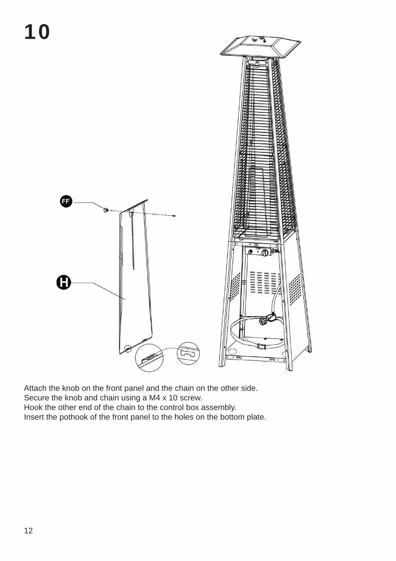
Attach the knob on the front panel and the chain on the other side.Secure the knob and chain using a M4 x 10 screw.Hook the other end of the chain to the control box assembly.Insert the pothook of the front panel to the holes on the bottom plate.
13
11
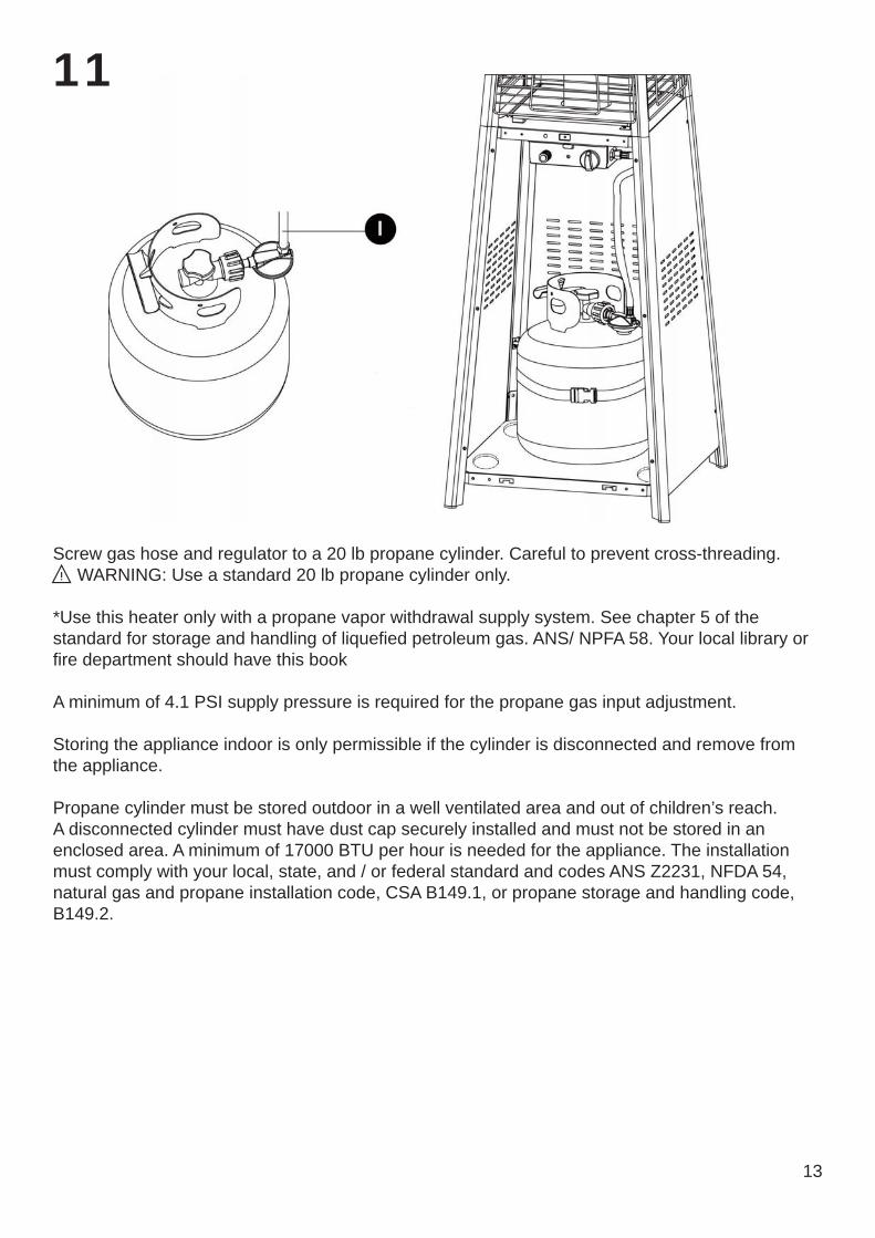
Screw gas hose and regulator to a 20 lb propane cylinder. Careful to prevent cross-threading.WARNING: Use a standard 20 lb propane cylinder only.
*Use this heater only with a propane vapor withdrawal supply system. See chapter 5 of the standard for storage and handling of liquefied petroleum gas. ANS/ NPFA 58. Your local library or fire department should have this book
A minimum of 4.1 PSI supply pressure is required for the propane gas input adjustment.
Storing the appliance indoor is only permissible if the cylinder is disconnected and remove from the appliance.
Propane cylinder must be stored outdoor in a well ventilated area and out of children’s reach. A disconnected cylinder must have dust cap securely installed and must not be stored in an enclosed area. A minimum of 17000 BTU per hour is needed for the appliance. The installation must comply with your local, state, and / or federal standard and codes ANS Z2231, NFDA 54, natural gas and propane installation code, CSA B149.1, or propane storage and handling code, B149.2.
WARNING
WARNING
15
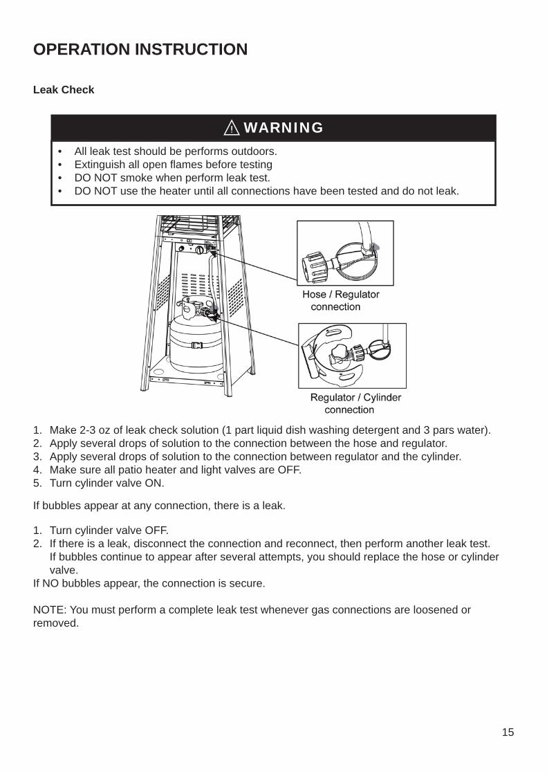
• All leak test should be performs outdoors.• Extinguish all open flames before testing• DO NOT smoke when perform leak test.• DO NOT use the heater until all connections have been tested and do not leak.
WARNING
OPERATION INSTRUCTION
Leak Check
1. Make 2-3 oz of leak check solution (1 part liquid dish washing detergent and 3 pars water).2. Apply several drops of solution to the connection between the hose and regulator.3. Apply several drops of solution to the connection between regulator and the cylinder.4. Make sure all patio heater and light valves are OFF.5. Turn cylinder valve ON.
1. Turn cylinder valve OFF.2. If there is a leak, disconnect the connection and reconnect, then perform another leak test.
If bubbles continue to appear after several attempts, you should replace the hose or cylinder valve.
If NO bubbles appear, the connection is secure.
NOTE: You must perform a complete leak test whenever gas connections are loosened or removed.
If bubbles appear at any connection, there is a leak.
WARNING
Before Turning Gas Supply ON
Before Lighting
This appliance shall be used only in a well-ventilated space and shall not be used in a building, garage or any other enclosed area.An appliance may be installed with shelter no more inclusive than:1)With walls on all sides, but with no overhead cover.2)Within a partial enclosure which includes an overhead cover and no more than two side walls.
These3)Within a partial enclosure which includes an overhead cover and three side walls, as long as 30percent or more of the horizontal periphery of the enclosure is permanently open.
This appliance shall be used only in a well-ventilated space and shall not be used in a building, ygarage or any other enclosed area.g g yAn appliance may be installed with shelter no more inclusive than:y1)With walls on all sides, but with no overhead cover.)2)Within a partial enclosure which includes an overhead cover and no more than two side walls.
These3)Within a partial enclosure which includes an overhead cover and three side walls, as long as 30)percent or more of the horizontal periphery of the enclosure is permanently open.
17
• DO NOT inhale fumes emitted from the heater in first use. Smoke and odorfrom burning manufacturing oil will appear. Smoke and odor will dissipate after approximately 30 minutes. The heater should NOT produce think black smoke.
CAUTION
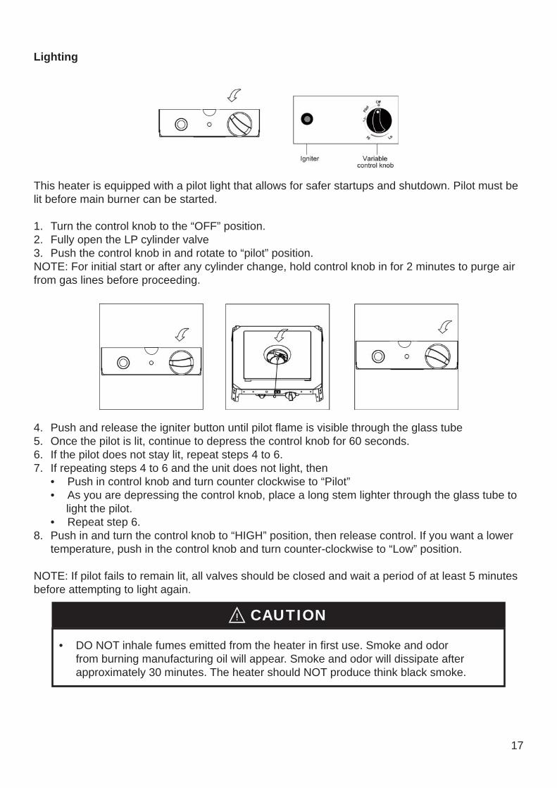
Lighting
This heater is equipped with a pilot light that allows for safer startups and shutdown. Pilot must be lit before main burner can be started.
1. Turn the control knob to the “OFF” position.2. Fully open the LP cylinder valve3. Push the control knob in and rotate to “pilot” position.NOTE: For initial start or after any cylinder change, hold control knob in for 2 minutes to purge air from gas lines before proceeding.
4. Push and release the igniter button until pilot flame is visible through the glass tube5. Once the pilot is lit, continue to depress the control knob for 60 seconds.6. If the pilot does not stay lit, repeat steps 4 to 6.7. If repeating steps 4 to 6 and the unit does not light, then
• Push in control knob and turn counter clockwise to “Pilot” • As you are depressing the control knob, place a long stem lighter through the glass tube to light the pilot. • Repeat step 6.
8. Push in and turn the control knob to “HIGH” position, then release control. If you want a lower temperature, push in the control knob and turn counter-clockwise to “Low” position.
NOTE: If pilot fails to remain lit, all valves should be closed and wait a period of at least 5 minutes before attempting to light again.
Re-lighting
Shut Down
WARNING
Operation Checklist
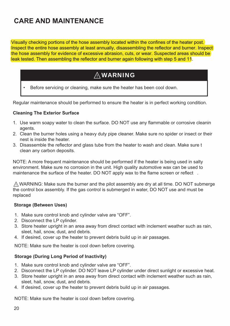
CARE AND MAINTENANCE
WARNING
Cleaning The Exterior Surface
Storage (Between Uses)
Storage (During Long Period of Inactivity)
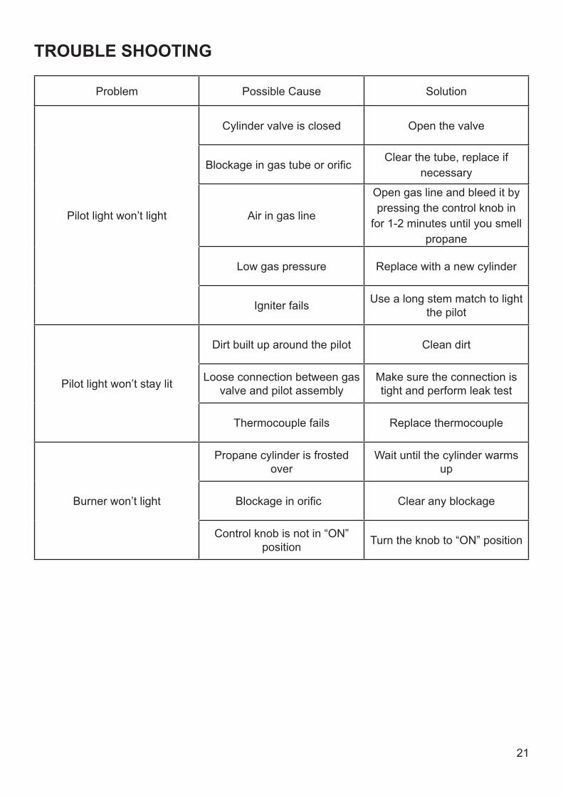
TROUBLE SHOOTING
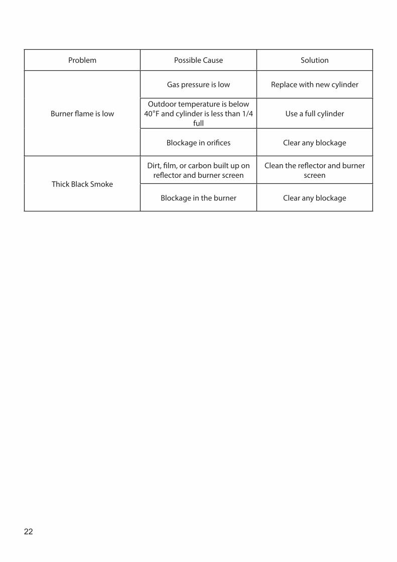
Problem Possible Cause Solution
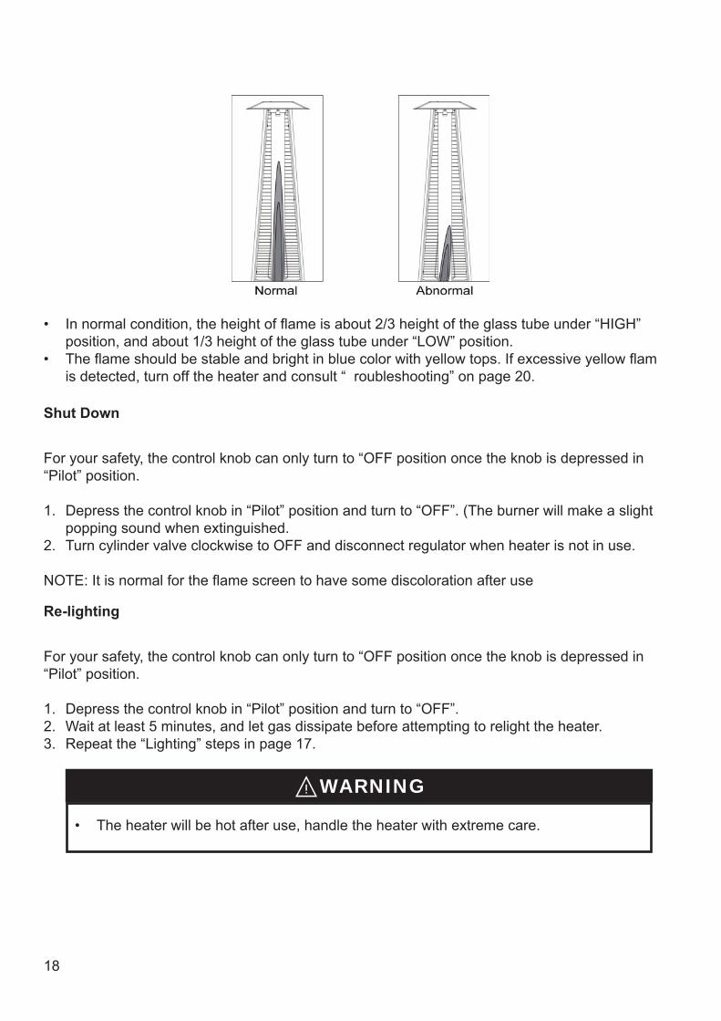
Burner flame is low
Gas pressure is low Replace with new cylinder
Outdoor temperature is below 40 F and cylinder is less than 1/4
fullUse a full cylinder
Blockage in orifices Clear any blockage
Thick Black Smoke
Dirt, film, or carbon built up on reflector and burner screen
Clean the reflector and burner screen
Blockage in the burner Clear any blockage

NOTE
Warranty
Register your product on our website to enjoy extended warranty!!
FOLLOW US: CONTACT INFO:
Easy Return
We hope you enjoy your new Belleze furniture!Share your photos on Instagram and tag us @bellezefurniture.
1-800-682-6376 [email protected]