Embed Size (px)
Citation preview
ALL STATED SPECIFICATIONS ARE SUBJECT TO CHANGE WITHOUT NOTICE OR OBLIGATION. ©Reliable April 2011Spec 4375DC-411/New
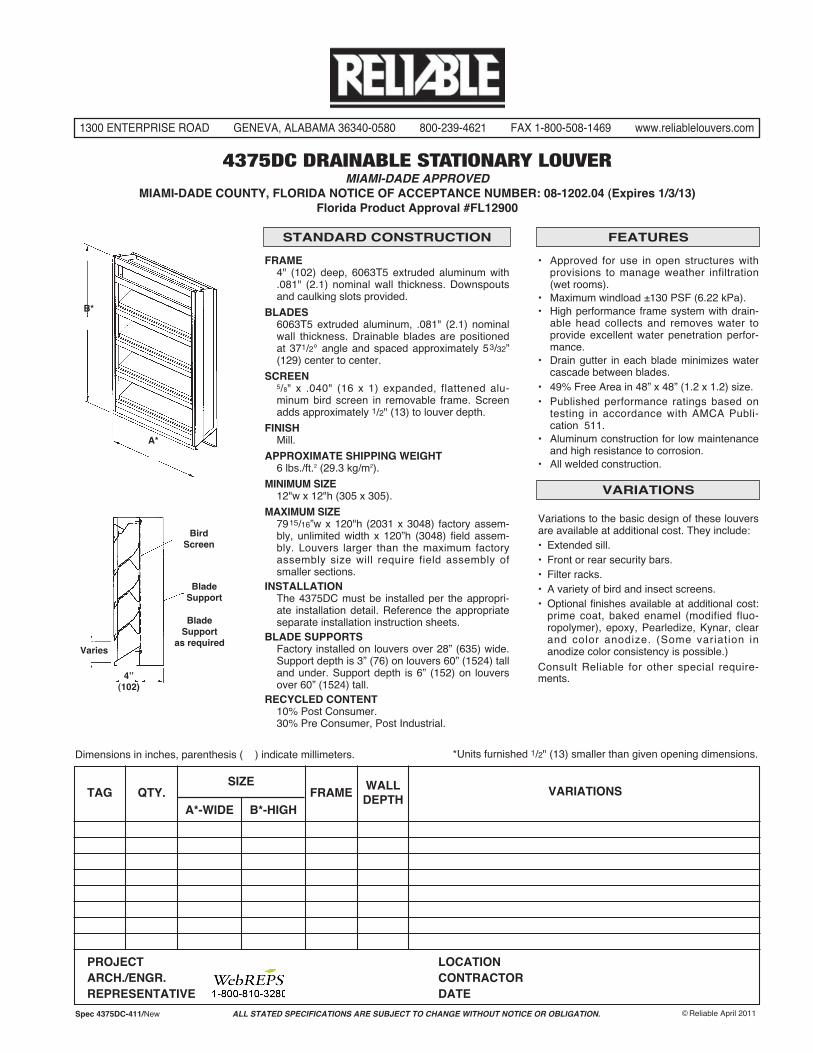
FRAME4" (102) deep, 6063T5 extruded aluminum with.081" (2.1) nominal wall thickness. Downspoutsand caulking slots provided.
BLADES6063T5 extruded aluminum, .081" (2.1) nominalwall thickness. Drainable blades are positionedat 371/2° angle and spaced approximately 53/32”(129) center to center.
SCREEN5/8" x .040" (16 x 1) expanded, flattened alu-minum bird screen in removable frame. Screenadds approximately 1/2" (13) to louver depth.
FINISHMill.
APPROXIMATE SHIPPING WEIGHT6 lbs./ft.2 (29.3 kg/m2).
MINIMUM SIZE12"w x 12"h (305 x 305).
MAXIMUM SIZE7915/16”w x 120"h (2031 x 3048) factory assem-bly, unlimited width x 120”h (3048) field assem-bly. Louvers larger than the maximum factoryassembly size will require field assembly ofsmaller sections.
INSTALLATIONThe 4375DC must be installed per the appropri-ate installation detail. Reference the appropriateseparate installation instruction sheets.
BLADE SUPPORTSFactory installed on louvers over 28” (635) wide.Support depth is 3” (76) on louvers 60” (1524) talland under. Support depth is 6” (152) on louversover 60” (1524) tall.
RECYCLED CONTENT10% Post Consumer.30% Pre Consumer, Post Industrial.
Variations to the basic design of these louversare available at additional cost. They include:• Extended sill.• Front or rear security bars.• Filter racks.• A variety of bird and insect screens.• Optional finishes available at additional cost:prime coat, baked enamel (modified fluo-ropolymer), epoxy, Pearledize, Kynar, clearand color anodize. (Some variation inanodize color consistency is possible.)
Consult Reliable for other special require-ments.
STANDARD CONSTRUCTION FEATURES
VARIATIONS
• Approved for use in open structures withprovisions to manage weather infiltration(wet rooms).
• Maximum windload ±130 PSF (6.22 kPa).• High performance frame system with drain-
able head collects and removes water toprovide excellent water penetration perfor-mance.
• Drain gutter in each blade minimizes watercascade between blades.
• 49% Free Area in 48” x 48” (1.2 x 1.2) size.• Published performance ratings based on
testing in accordance with AMCA Publi-cation 511.
• Aluminum construction for low maintenanceand high resistance to corrosion.
• All welded construction.
1300 ENTERPRISE ROAD GENEVA, ALABAMA 36340-0580 800-239-4621 FAX 1-800-508-1469 www.reliablelouvers.com
4375DC DRAINABLE STATIONARY LOUVERMIAMI-DADE APPROVED
MIAMI-DADE COUNTY, FLORIDA NOTICE OF ACCEPTANCE NUMBER: 08-1202.04 (Expires 1/3/13)Florida Product Approval #FL12900
B*
A*
Varies
BirdScreen
BladeSupport
BladeSupport
as required
4”(102)
SIZETAG QTY. FRAME
WALLDEPTH
A*-WIDE B*-HIGH
VARIATIONS
PROJECT LOCATIONARCH./ENGR. CONTRACTORREPRESENTATIVE DATE
*Units furnished 1/2" (13) smaller than given opening dimensions.Dimensions in inches, parenthesis ( ) indicate millimeters.
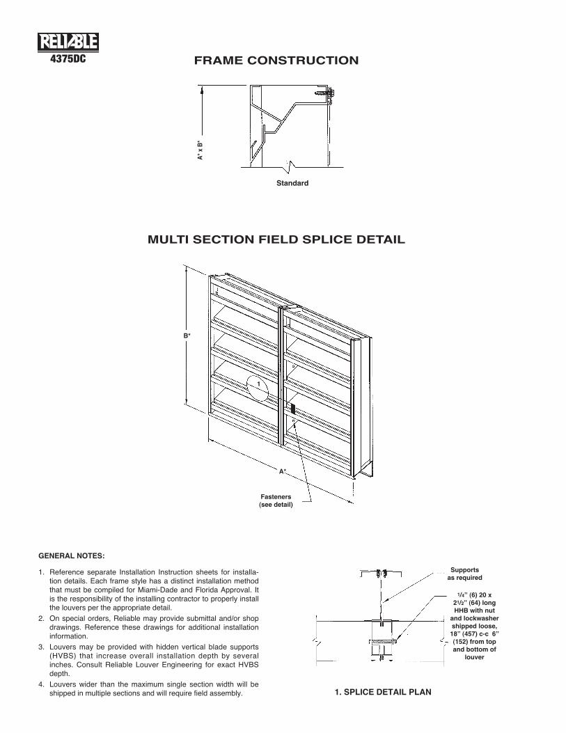
FRAME CONSTRUCTION4375DC
MULTI SECTION FIELD SPLICE DETAIL
1. Reference separate Installation Instruction sheets for installa-tion details. Each frame style has a distinct installation methodthat must be compiled for Miami-Dade and Florida Approval. Itis the responsibility of the installing contractor to properly installthe louvers per the appropriate detail.
2. On special orders, Reliable may provide submittal and/or shopdrawings. Reference these drawings for additional installationinformation.
3. Louvers may be provided with hidden vertical blade supports(HVBS) that increase overall installation depth by severalinches. Consult Reliable Louver Engineering for exact HVBSdepth.
4. Louvers wider than the maximum single section width will beshipped in multiple sections and will require field assembly.
Standard
A*xB*
1. SPLICE DETAIL PLAN
B*
A*
Fasteners(see detail)
1
Supportsas required
1/4” (6) 20 x21/2” (64) longHHB with nut
and lockwashershipped loose,18” (457) c-c 6”(152) from topand bottom of
louver
GENERAL NOTES:
4375DC
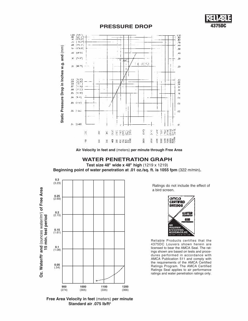
WATER PENETRATION GRAPHTest size 48" wide x 48" high (1219 x 1219)
Beginning point of water penetration at .01 oz./sq. ft. is 1055 fpm (322 m/min).
Reliable Products certif ies that the4375DC Louvers shown herein arelicensed to bear the AMCA Seal. The rat-ings shown are based on tests and proce-dures performed in accordance withAMCA Publication 511 and comply withthe requirements of the AMCA CertifiedRatings Program. The AMCA CertifiedRatings Seal applies to air performanceratings and water penetration ratings only.
Ratings do not include the effect ofa bird screen.
PRESSURE DROP
StaticPressure
DropinInches
w.g.and(m
m)
Air Velocity in feet and (meters) per minute through Free Area
Free Area Velocity in feet (meters) per minuteStandard air .075 lb/ft3
Oz.Water/ft2and(ounceswater/m
2 )ofFreeArea
15min.testperiod
900(274)
1000(305)
1100(335)
1200(366)
0.3(3.23)
0.25(2.69)
0.2(2.15)
0.15(1.61)
0.1(1.08)
0.05(.54)
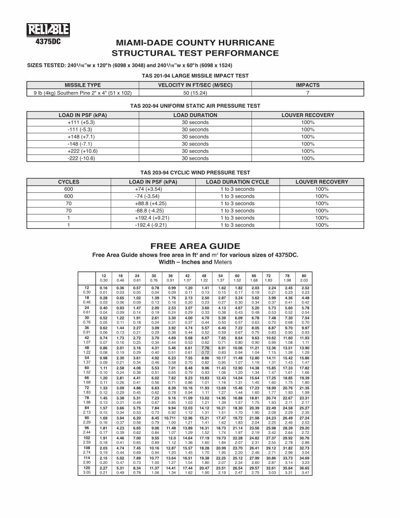
FREE AREA GUIDEFree Area Guide shows free area in ft2 and m2 for various sizes of 4375DC.
Width – Inches and Meters
4375DC
120.3018
0.4624
0.6130
0.7636
0.9142
1.0748
1.2254
1.3760
1.5266
1.6872
1.8378
1.9884
2.1390
2.2996
2.441022.591082.741142.901203.05
0.16 0.36 0.57 0.78 0.99 1.20 1.41 1.62 1.82 2.03 2.24 2.45 2.520.01 0.03 0.05 0.04 0.09 0.11 0.13 0.15 0.17 0.19 0.21 0.23 0.230.28 0.65 1.02 1.39 1.76 2.13 2.50 2.87 3.24 3.62 3.99 4.36 4.480.03 0.06 0.09 0.13 0.16 0.20 0.23 0.27 0.30 0.34 0.37 0.41 0.420.40 0.93 1.47 2.00 2.53 3.07 3.60 4.13 4.67 5.20 5.73 5.60 5.780.04 0.09 0.14 0.19 0.24 0.29 0.33 0.38 0.43 0.48 0.53 0.52 0.540.52 1.22 1.91 2.61 3.30 4.00 4.70 5.39 6.09 6.78 7.48 7.30 7.540.05 0.11 0.18 0.24 0.31 0.37 0.44 0.50 0.57 0.63 0.70 0.68 0.700.62 1.44 2.27 3.09 3.92 4.74 5.57 6.40 7.22 8.05 8.87 9.70 9.970.06 0.13 0.21 0.29 0.36 0.44 0.52 0.59 0.67 0.75 0.83 0.90 0.930.74 1.73 2.72 3.70 4.69 5.68 6.67 7.65 8.64 9.63 10.62 11.60 11.930.07 0.16 0.25 0.34 0.44 0.53 0.62 0.71 0.80 0.90 0.99 1.08 1.110.86 2.01 3.16 4.31 5.46 6.61 7.76 8.91 10.06 11.21 12.36 13.51 13.900.08 0.19 0.29 0.40 0.51 0.61 0.72 0.83 0.94 1.04 1.15 1.26 1.290.98 2.30 3.61 4.92 6.23 7.55 8.86 10.17 11.48 12.80 14.11 15.42 15.860.09 0.21 0.34 0.46 0.58 0.70 0.82 0.95 1.07 1.19 1.31 1.43 1.471.11 2.58 4.06 5.53 7.01 8.48 9.96 11.43 12.90 14.38 15.85 17.33 17.820.10 0.24 0.38 0.51 0.65 0.79 0.93 1.06 1.20 1.34 1.47 1.61 1.661.20 2.81 4.41 6.02 7.62 9.23 10.83 12.43 14.04 15.64 17.25 18.85 19.390.11 0.26 0.41 0.56 0.71 0.86 1.01 1.16 1.31 1.45 1.60 1.75 1.801.33 3.09 4.86 6.63 8.39 10.16 11.93 13.69 15.46 17.23 18.99 20.76 21.350.12 0.29 0.45 0.62 0.78 0.94 1.11 1.27 1.44 1.60 1.77 1.93 1.991.45 3.38 5.31 7.23 9.16 11.09 13.02 14.95 16.88 18.81 20.74 22.67 23.310.13 0.31 0.49 0.67 0.85 1.03 1.21 1.39 1.57 1.75 1.93 2.11 2.171.57 3.66 5.75 7.84 9.94 12.03 14.12 16.21 18.30 20.39 22.49 24.58 25.270.15 0.34 0.53 0.73 0.92 1.12 1.31 1.51 1.70 1.90 2.09 2.29 2.351.69 3.94 6.20 8.45 10.711 12.96 15.21 17.47 19.72 21.98 24.23 26.49 27.240.16 0.37 0.58 0.79 1.00 1.21 1.41 1.62 1.83 2.04 2.25 2.46 2.531.81 4.23 6.65 9.06 11.48 13.89 16.31 18.73 21.14 23.56 25.98 28.39 29.200.17 0.39 0.62 0.84 1.07 1.29 1.52 1.74 1.97 2.19 2.42 2.64 2.721.91 4.46 7.00 9.55 12.0 14.64 17.19 19.73 22.28 24.82 27.37 29.92 30.760.18 0.41 0.65 0.89 1.12 1.36 1.60 1.84 2.07 2.31 2.55 2.78 2.862.03 4.74 7.45 10.16 12.87 15.57 18.28 20.99 23.70 26.41 29.12 31.82 32.730.19 0.44 0.69 0.94 1.20 1.45 1.70 1.95 2.20 2.46 2.71 2.96 3.042.15 5.02 7.89 10.77 13.64 16.51 19.38 22.25 25.12 27.99 30.86 33.73 34.690.20 0.47 0.73 1.00 1.27 1.54 1.80 2.07 2.34 2.60 2.87 3.14 3.232.27 5.31 8.34 11.37 14.41 17.44 20.47 23.51 26.54 29.57 32.61 35.64 36.650.21 0.49 0.78 1.06 1.34 1.62 1.90 2.19 2.47 2.75 3.03 3.31 3.41
120.30
180.46
240.61
300.76
360.91
421.07
481.22
541.37
601.52
661.68
721.83
781.98
802.03
MIAMI-DADE COUNTY HURRICANESTRUCTURAL TEST PERFORMANCE
SIZES TESTED: 2401/16”w x 120"h (6098 x 3048) and 2401/16”w x 60"h (6098 x 1524)
TAS 201-94 LARGE MISSILE IMPACT TEST
MISSILE TYPE
9 lb (4kg) Southern Pine 2" x 4" (51 x 102) 50 (15.24) 7
VELOCITY IN FT/SEC (M/SEC) IMPACTS
TAS 202-94 UNIFORM STATIC AIR PRESSURE TEST
LOAD IN PSF (kPA)+111 (+5.3)-111 (-5.3)+148 (+7.1)-148 (-7.1)+222 (+10.6)-222 (-10.6)
30 seconds30 seconds30 seconds30 seconds30 seconds30 seconds
100%100%100%100%100%100%
LOAD DURATION LOUVER RECOVERY
TAS 203-94 CYCLIC WIND PRESSURE TEST
CYCLES LOAD IN PSF (kPA)600600707011
+74 (+3.54)-74 (-3.54)+88.8 (+4.25)-88.8 (-4.25)+192.4 (+9.21)-192.4 (-9.21)
1 to 3 seconds1 to 3 seconds1 to 3 seconds1 to 3 seconds1 to 3 seconds1 to 3 seconds
100%100%100%100%100%100%
LOAD DURATION CYCLE LOUVER RECOVERY
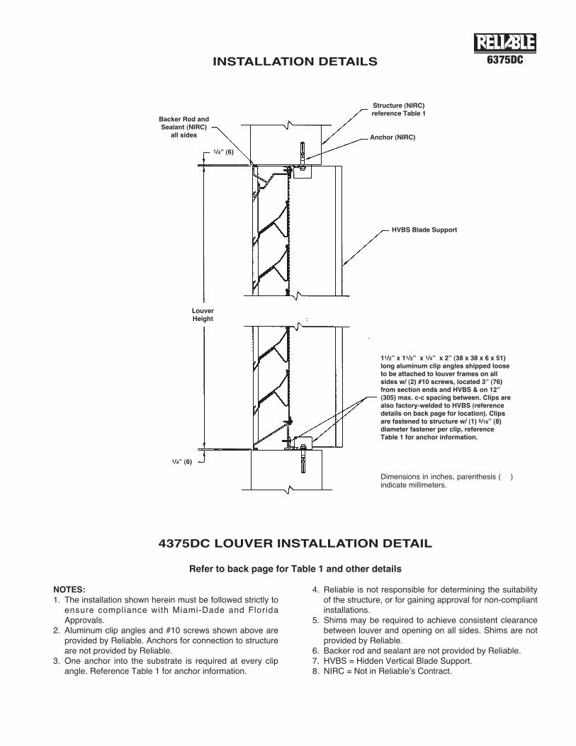
Refer to back page for Table 1 and other details
4375DC LOUVER INSTALLATION DETAIL
NOTES:1. The installation shown herein must be followed strictly to
ensure compliance with Miami-Dade and FloridaApprovals.
2. Aluminum clip angles and #10 screws shown above areprovided by Reliable. Anchors for connection to structureare not provided by Reliable.
3. One anchor into the substrate is required at every clipangle. Reference Table 1 for anchor information.
4. Reliable is not responsible for determining the suitabilityof the structure, or for gaining approval for non-compliantinstallations.
5. Shims may be required to achieve consistent clearancebetween louver and opening on all sides. Shims are notprovided by Reliable.
6. Backer rod and sealant are not provided by Reliable.7. HVBS = Hidden Vertical Blade Support.8. NIRC = Not in Reliableʼs Contract.
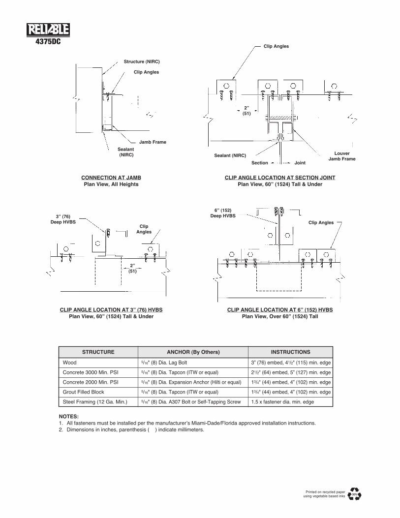
11/2” x 11/2” x 1/4” x 2” (38 x 38 x 6 x 51)long aluminum clip angles shipped looseto be attached to louver frames on allsides w/ (2) #10 screws, located 3” (76)from section ends and HVBS & on 12”(305) max. c-c spacing between. Clips arealso factory-welded to HVBS (referencedetails on back page for location). Clipsare fastened to structure w/ (1) 5/16” (8)diameter fastener per clip, referenceTable 1 for anchor information.
HVBS Blade Support
LouverHeight
1/4” (6)
1/4” (6)
Structure (NIRC)reference Table 1
Anchor (NIRC)
Dimensions in inches, parenthesis ( )indicate millimeters.
Backer Rod andSealant (NIRC)
all sides
INSTALLATION DETAILS 6375DC
Printed on recycled paperusing vegetable based inks
STRUCTURE ANCHOR (By Others) INSTRUCTIONS
Wood
Concrete 3000 Min. PSI
Concrete 2000 Min. PSI
Grout Filled Block
Steel Framing (12 Ga. Min.)
5/16" (8) Dia. Lag Bolt
5/16" (8) Dia. Tapcon (ITW or equal)
5/16" (8) Dia. Expansion Anchor (Hilti or equal)
5/16" (8) Dia. Tapcon (ITW or equal)
5/16" (8) Dia. A307 Bolt or Self-Tapping Screw
3” (76) embed, 41/2" (115) min. edge
21/2" (64) embed, 5” (127) min. edge
13/4" (44) embed, 4” (102) min. edge
13/4" (44) embed, 4” (102) min. edge
1.5 x fastener dia. min. edge
CONNECTION AT JAMBPlan View, All Heights
CLIP ANGLE LOCATION AT SECTION JOINTPlan View, 60” (1524) Tall & Under
Structure (NIRC)
Clip Angles
Jamb Frame
Sealant(NIRC)
CLIP ANGLE LOCATION AT 3” (76) HVBSPlan View, 60” (1524) Tall & Under
CLIP ANGLE LOCATION AT 6” (152) HVBSPlan View, Over 60” (1524) Tall
3” (76)Deep HVBS
2”(51)
Clip Angles
Sealant (NIRC)
Section Joint
LouverJamb Frame
ClipAngles
Clip Angles
6” (152)Deep HVBS
NOTES:1. All fasteners must be installed per the manufacturerʼs Miami-Dade/Florida approved installation instructions.2. Dimensions in inches, parenthesis ( ) indicate millimeters.
2”(51)
4375DC
ALL STATED SPECIFICATIONS ARE SUBJECT TO CHANGE WITHOUT NOTICE OR OBLIGATION. ©Reliable April 2011Spec 6375DC-411/New
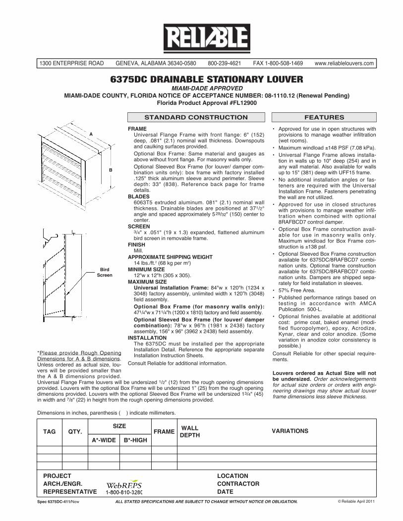
STANDARD CONSTRUCTION FEATURES
• Approved for use in open structures withprovisions to manage weather infiltration(wet rooms).
• Maximum windload ±148 PSF (7.08 kPa).• Universal Flange Frame allows installa-
tion in walls up to 10" deep (254) and inany wall material. Also available for wallsup to 15" (381) deep with UFF15 frame.
• No additional installation angles or fas-teners are required with the UniversalInstallation Frame. Fasteners penetratingthe wall are not utilized.
• Approved for use in closed structureswith provisions to manage weather infil-tration when combined with optional8RAFBCD7 control damper.
• Optional Box Frame construction avail-able for use in masonry walls only.Maximum windload for Box Frame con-struction is ±138 psf.
• Optional Sleeved Box Frame constructionavailable for 6375DC/8RAFBCD7 combi-nation units. Optional frame constructionavailable for 6375DC/8RAFBCD7 combi-nation units. Dampers are shipped sepa-rately for field installation in sleeves.
• 57% Free Area.• Published performance ratings based on
testing in accordance with AMCAPublication 500-L.
• Optional finishes available at additionalcost: prime coat, baked enamel (modi-fied fluoropolymer), epoxy, Acrodize,Kynar, clear and color anodize. (Somevariation in anodize color consistency ispossible.)
Consult Reliable for other special require-ments.
Louvers ordered as Actual Size will notbe undersized. Order acknowledgementsfor actual size orders or orders with engi-neering drawings may show actual louverframe dimensions less sleeve thickness.
1300 ENTERPRISE ROAD GENEVA, ALABAMA 36340-0580 800-239-4621 FAX 1-800-508-1469 www.reliablelouvers.com
6375DC DRAINABLE STATIONARY LOUVERMIAMI-DADE APPROVED
MIAMI-DADE COUNTY, FLORIDA NOTICE OF ACCEPTANCE NUMBER: 08-1110.12 (Renewal Pending)Florida Product Approval #FL12900
Dimensions in inches, parenthesis ( ) indicate millimeters.
BirdScreen
A
SIZETAG QTY. FRAME
WALLDEPTH
A*-WIDE B*-HIGH
VARIATIONS
PROJECT LOCATIONARCH./ENGR. CONTRACTORREPRESENTATIVE DATE
*Please provide Rough OpeningDimensions for A & B dimensions.Unless ordered as actual size, lou-vers will be provided smaller thanthe A & B dimensions provided.Universal Flange Frame louvers will be undersized 1/2" (12) from the rough opening dimensionsprovided. Louvers with the optional Box Frame will be undersized 1” (25) from the rough openingdimensions provided. Louvers with the optional Sleeved Box Frame will be undersized 13/4" (45)in width and 7/8" (22) in height from the rough opening dimensions provided.
FRAMEUniversal Flange Frame with front flange: 6" (152)deep, .081" (2.1) nominal wall thickness. Downspoutsand caulking surfaces provided.Optional Box Frame: Same material and gauges asabove without front flange. For masonry walls only.Optional Sleeved Box Frame (for louver/ damper com-bination units only): box frame with factory installed.125" thick aluminum sleeve around perimeter. Sleevedepth: 33" (838). Reference back page for framedetails.
BLADES6063T5 extruded aluminum. 081" (2.1) nominal wallthickness. Drainable blades are positioned at 371/2°angle and spaced approximately 529/32" (150) center tocenter.
SCREEN3/4" x .051" (19 x 1.3) expanded, flattened aluminumbird screen in removable frame.
FINISHMill.
APPROXIMATE SHIPPING WEIGHT14 lbs./ft.2 (68 kg per m2)
MINIMUM SIZE12"w x 12"h (305 x 305).
MAXIMUM SIZEUniversal Installation Frame: 84"w x 120"h (1234 x3048) factory assembly, unlimited width x 120”h (3048)field assembly.Optional Box Frame (for masonry walls only):471/4"w x 711/4"h (1200 x 1810) factory and field assembly.Optional Sleeved Box Frame (for louver/ dampercombination): 78"w x 96"h (1981 x 2438) factoryassembly, 156" x 96" (3962 x 2438) field assembly.
INSTALLATIONThe 6375DC must be installed per the appropriateInstallation Detail. Reference the appropriate separateInstallation Instruction Sheets.
Consult Reliable for additional information.
B
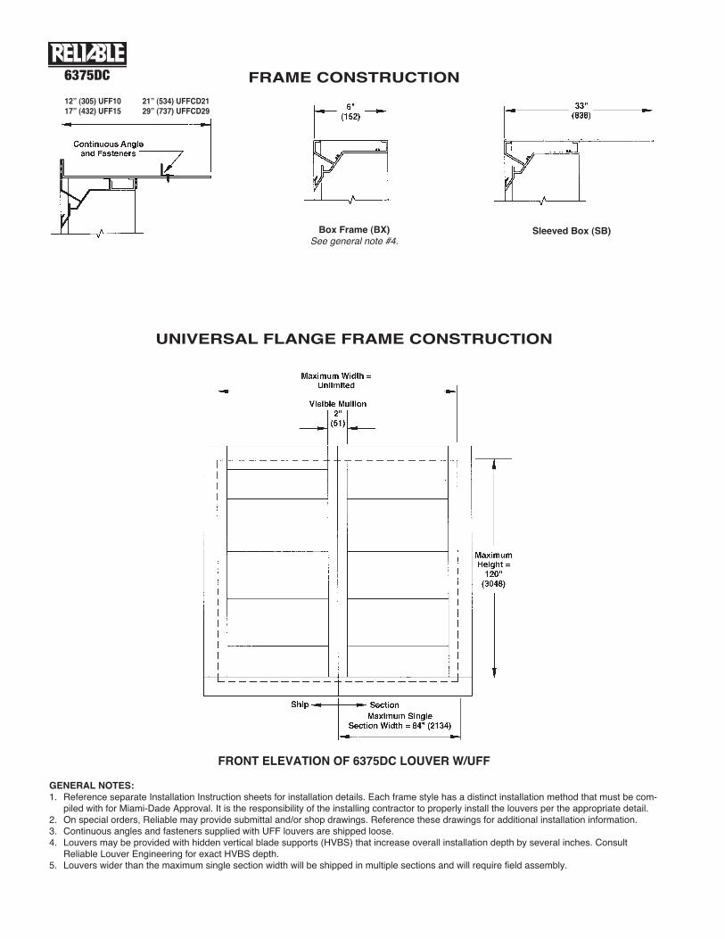
FRAME CONSTRUCTION6375DC
UNIVERSAL FLANGE FRAME CONSTRUCTION
Box Frame (BX)See general note #4.
Sleeved Box (SB)
12” (305) UFF1017” (432) UFF15
21” (534) UFFCD2129” (737) UFFCD29
GENERAL NOTES:1. Reference separate Installation Instruction sheets for installation details. Each frame style has a distinct installation method that must be com-
piled with for Miami-Dade Approval. It is the responsibility of the installing contractor to properly install the louvers per the appropriate detail.2. On special orders, Reliable may provide submittal and/or shop drawings. Reference these drawings for additional installation information.3. Continuous angles and fasteners supplied with UFF louvers are shipped loose.4. Louvers may be provided with hidden vertical blade supports (HVBS) that increase overall installation depth by several inches. Consult
Reliable Louver Engineering for exact HVBS depth.5. Louvers wider than the maximum single section width will be shipped in multiple sections and will require field assembly.
FRONT ELEVATION OF 6375DC LOUVER W/UFF
6375DC
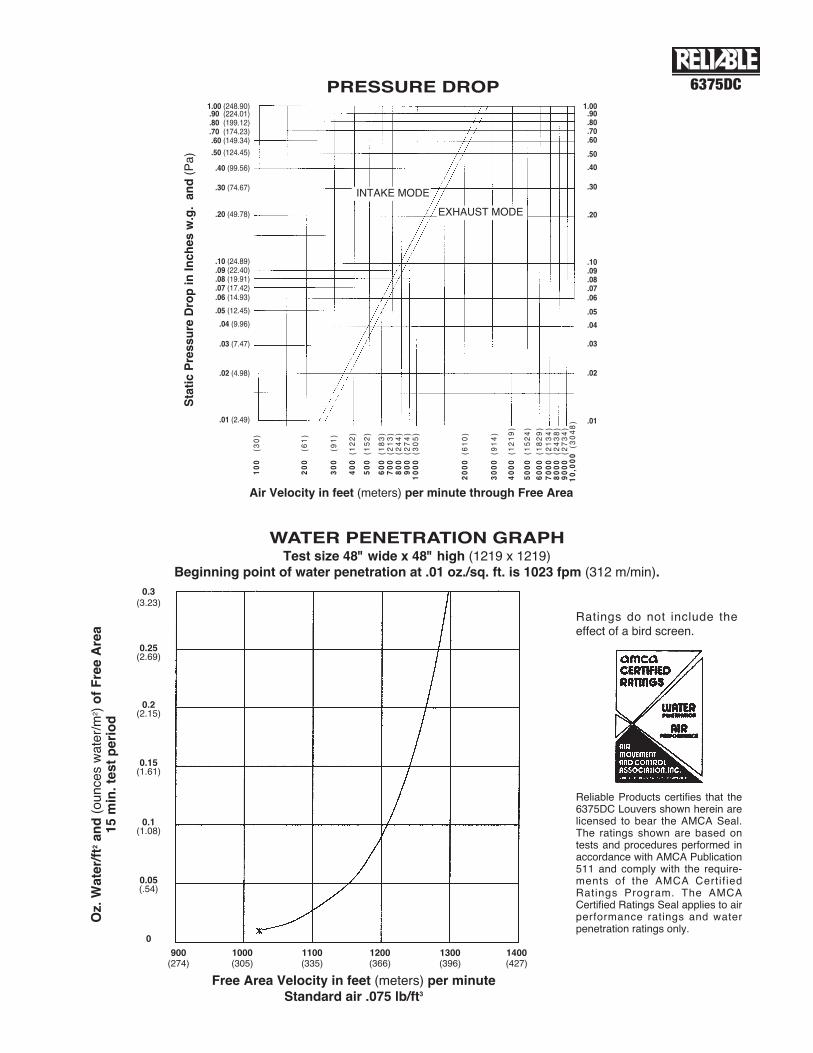
Reliable Products certifies that the6375DC Louvers shown herein arelicensed to bear the AMCA Seal.The ratings shown are based ontests and procedures performed inaccordance with AMCA Publication511 and comply with the require-ments of the AMCA Certif iedRatings Program. The AMCACertified Ratings Seal applies to airperformance ratings and waterpenetration ratings only.
Ratings do not include theeffect of a bird screen.
PRESSURE DROP
EXHAUST MODE
INTAKE MODE
1.00 (248.90).90 (224.01).80 (199.12).70 (174.23).60 (149.34)
.50 (124.45)
.40 (99.56)
.30 (74.67)
.20 (49.78)
.10 (24.89)
.09 (22.40)
.08 (19.91)
.07 (17.42)
.06 (14.93)
.05 (12.45)
.04 (9.96)
.03 (7.47)
.02 (4.98)
.01 (2.49)
1.00.90.80.70.60
.50
.40
.30
.20
.10
.09
.08
.07
.06
.05
.04
.03
.02
.01
100
(30)
200
(61)
300
(91)
400
(122)
500
(152)
600
(183)
700
(213)
800
(244)
900
(274)
1000
(305)
2000
(610)
3000
(914)
4000
(1219)
5000
(1524)
6000
(1829)
7000
(2134)
8000
(2438)
9000
(2734)
10,000
(3048)
StaticPressure
DropinInches
w.g.and(Pa)
Air Velocity in feet (meters) per minute through Free Area
WATER PENETRATION GRAPHTest size 48" wide x 48" high (1219 x 1219)
Beginning point of water penetration at .01 oz./sq. ft. is 1023 fpm (312 m/min).
Oz.Water/ft2and(ounceswater/m
2 )ofFreeArea
15min.testperiod
0.3(3.23)
0.25(2.69)
0.2(2.15)
0.15(1.61)
0.1(1.08)
0.05(.54)
0
900(274)
1000(305)
1100(335)
1200(366)
1300(396)
1400(427)
Free Area Velocity in feet (meters) per minuteStandard air .075 lb/ft3
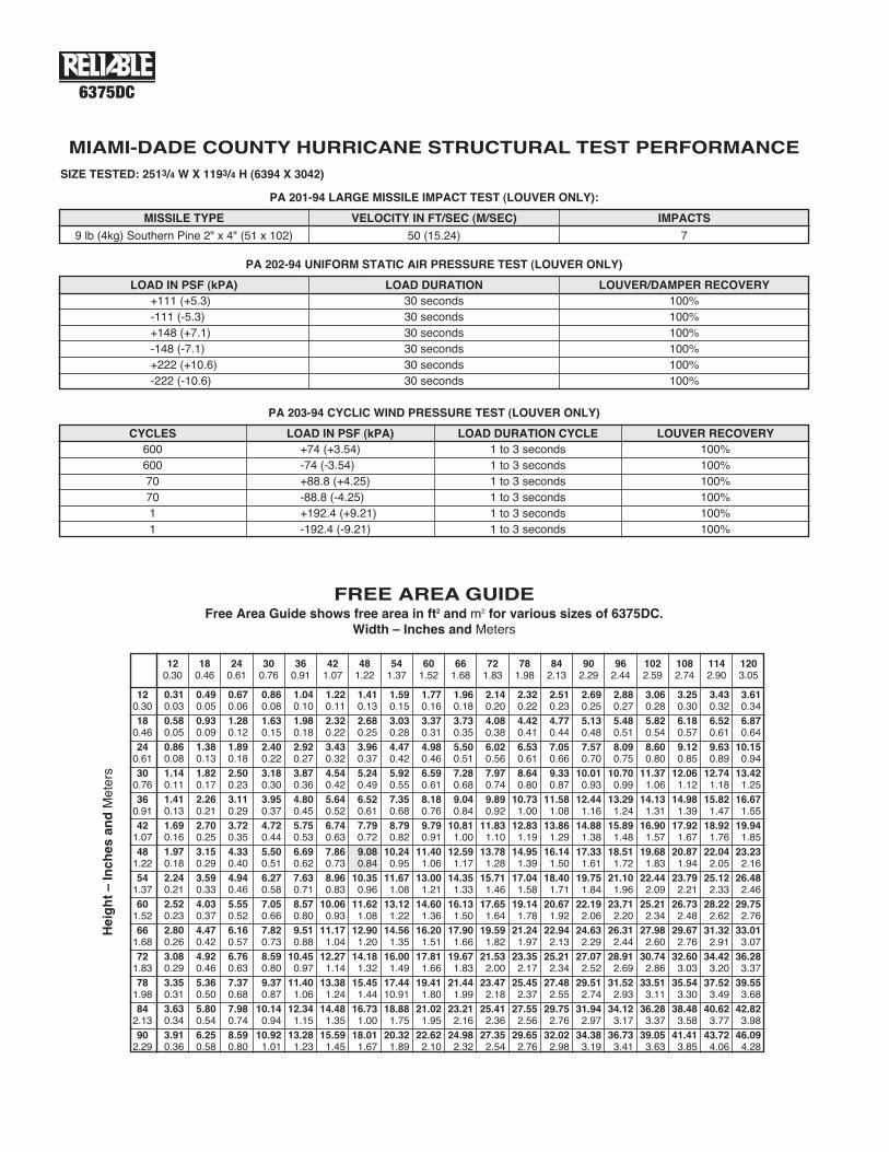
FREE AREA GUIDEFree Area Guide shows free area in ft2 and m2 for various sizes of 6375DC.
Width – Inches and Meters
6375DC
MIAMI-DADE COUNTY HURRICANE STRUCTURAL TEST PERFORMANCESIZE TESTED: 2513/4 W X 1193/4 H (6394 X 3042)
PA 201-94 LARGE MISSILE IMPACT TEST (LOUVER ONLY):
MISSILE TYPE
9 lb (4kg) Southern Pine 2" x 4" (51 x 102) 50 (15.24) 7
VELOCITY IN FT/SEC (M/SEC) IMPACTS
PA 202-94 UNIFORM STATIC AIR PRESSURE TEST (LOUVER ONLY)
LOAD IN PSF (kPA)+111 (+5.3)-111 (-5.3)+148 (+7.1)-148 (-7.1)+222 (+10.6)-222 (-10.6)
30 seconds30 seconds30 seconds30 seconds30 seconds30 seconds
100%100%100%100%100%100%
LOAD DURATION LOUVER/DAMPER RECOVERY
PA 203-94 CYCLIC WIND PRESSURE TEST (LOUVER ONLY)
CYCLES LOAD IN PSF (kPA)600600707011
+74 (+3.54)-74 (-3.54)+88.8 (+4.25)-88.8 (-4.25)+192.4 (+9.21)-192.4 (-9.21)
1 to 3 seconds1 to 3 seconds1 to 3 seconds1 to 3 seconds1 to 3 seconds1 to 3 seconds
100%100%100%100%100%100%
LOAD DURATION CYCLE LOUVER RECOVERY
Height–Inches
andMeters
0.310.030.580.050.860.081.140.111.410.131.690.161.970.182.240.212.520.232.800.263.080.293.350.313.630.343.910.36
0.490.050.930.091.380.131.820.172.260.212.700.253.150.293.590.334.030.374.470.424.920.465.360.505.800.546.250.58
0.670.061.280.121.890.182.500.233.110.293.720.354.330.404.940.465.550.526.160.576.760.637.370.687.980.748.590.80
0.860.081.630.152.400.223.180.303.950.374.720.445.500.516.270.587.050.667.820.738.590.809.370.8710.140.9410.921.01
1.040.101.980.182.920.273.870.364.800.455.750.536.690.627.630.718.570.809.510.8810.450.9711.401.0612.341.1513.281.23
1.220.112.320.223.430.324.540.425.640.526.740.637.860.738.960.8310.060.9311.171.0412.271.1413.381.2414.481.3515.591.45
1.410.132.680.253.960.375.240.496.520.617.790.729.080.8410.350.9611.621.0812.901.2014.181.3215.451.4416.731.0018.011.67
1.590.153.030.284.470.425.920.557.350.688.790.8210.240.9511.671.0813.121.2214.561.3516.001.4917.4410.9118.881.7520.321.89
1.770.163.370.314.980.466.590.618.180.769.790.9111.401.0613.001.2114.601.3616.201.5117.811.6619.411.8021.021.9522.622.10
1.960.183.730.355.500.517.280.689.040.8410.811.0012.591.1714.351.3316.131.5017.901.6619.671.8321.441.9923.212.1624.982.32
2.140.204.080.386.020.567.970.749.890.9211.831.1013.781.2815.711.4617.651.6419.591.8221.532.0023.472.1825.412.3627.352.54
2.320.224.420.416.530.618.640.8010.731.0012.831.1914.951.3917.041.5819.141.7821.241.9723.352.1725.452.3727.552.5629.652.76
2.510.234.770.447.050.669.330.8711.581.0813.861.2916.141.5018.401.7120.671.9222.942.1325.212.3427.482.5529.752.7632.022.98
2.690.255.130.487.570.7010.010.9312.441.1614.881.3817.331.6119.751.8422.192.0624.632.2927.072.5229.512.7431.942.9734.383.19
2.880.275.480.518.090.7510.700.9913.291.2415.891.4818.511.7221.101.9623.712.2026.312.4428.912.6931.522.9334.123.1736.733.41
3.060.285.820.548.600.8011.371.0614.131.3116.901.5719.681.8322.442.0925.212.3427.982.6030.742.8633.513.1136.283.3739.053.63
3.250.306.180.579.120.8512.061.1214.981.3917.921.6720.871.9423.792.2126.732.4829.672.7632.603.0335.543.3038.483.5841.413.85
3.430.326.520.619.630.8912.741.1815.821.4718.921.7622.042.0525.122.3328.222.6231.322.9134.423.2037.523.4940.623.7743.724.06
3.610.346.870.6410.150.9413.421.2516.671.5519.941.8523.232.1626.482.4629.752.7633.013.0736.283.3739.553.6842.823.9846.094.28
120.30180.46240.61300.76360.91421.07481.22541.37601.52661.68721.83781.98842.13902.29
120.30
180.46
240.61
300.76
360.91
421.07
481.22
541.37
601.52
661.68
721.83
781.98
842.13
902.29
962.44
1022.59
1082.74
1142.90
1203.05
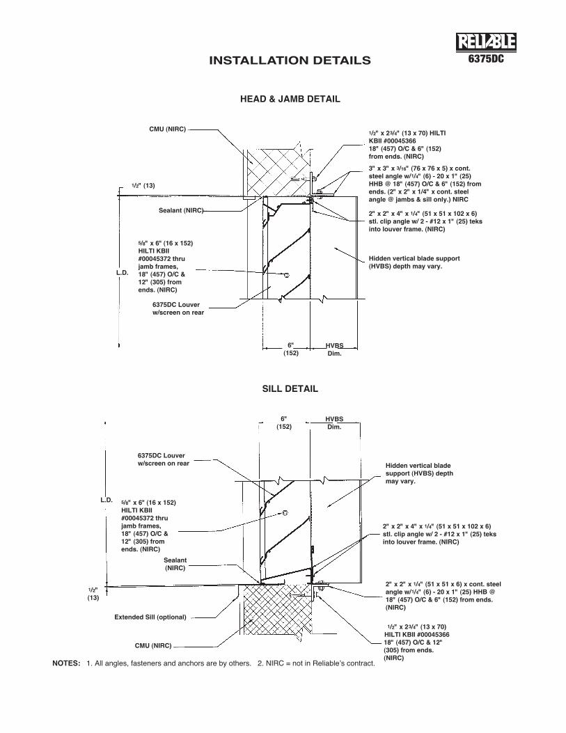
INSTALLATION DETAILS 6375DC
HEAD & JAMB DETAIL
SILL DETAIL
CMU (NIRC)
1/2" (13)
6"(152)
HVBSDim.
L.D.
Sealant (NIRC)
5/8" x 6" (16 x 152)HILTI KBII#00045372 thrujamb frames,18" (457) O/C &12" (305) fromends. (NIRC)
1/2" x 23/4" (13 x 70) HILTIKBII #0004536618" (457) O/C & 6" (152)from ends. (NIRC)
3" x 3" x 3/16" (76 x 76 x 5) x cont.steel angle w/1/4" (6) - 20 x 1" (25)HHB @ 18" (457) O/C & 6" (152) fromends. (2" x 2" x 1/4" x cont. steelangle @ jambs & sill only.) NIRC
2" x 2" x 4" x 1/4" (51 x 51 x 102 x 6)stl. clip angle w/ 2 - #12 x 1" (25) teksinto louver frame. (NIRC)
Hidden vertical blade support(HVBS) depth may vary.
6375DC Louverw/screen on rear
CMU (NIRC)
1/2" x 23/4" (13 x 70)HILTI KBII #0004536618" (457) O/C & 12"(305) from ends.(NIRC)
1/2"(13)
6"(152)
HVBSDim.
L.D.
Sealant(NIRC)
Extended Sill (optional)
5/8" x 6" (16 x 152)HILTI KBII#00045372 thrujamb frames,18" (457) O/C &12" (305) fromends. (NIRC)
6375DC Louverw/screen on rear
2" x 2" x 1/4" (51 x 51 x 6) x cont. steelangle w/1/4" (6) - 20 x 1" (25) HHB @18" (457) O/C & 6" (152) from ends.(NIRC)
2" x 2" x 4" x 1/4" (51 x 51 x 102 x 6)stl. clip angle w/ 2 - #12 x 1" (25) teksinto louver frame. (NIRC)
Hidden vertical bladesupport (HVBS) depthmay vary.
NOTES: 1. All angles, fasteners and anchors are by others. 2. NIRC = not in Reliableʼs contract.