Embed Size (px)
Citation preview

DAVIS, M.J., Chester, R.J., Perl, D.R., Pomerleau, E., Vallerand, M., Honeycomb Bond and Core
Durability Issues; Experiences within CREDP Nations, Aging Aircraft Conference, Williamsberg, VA,
Aug 31-Sep 02 1998.
HONEYCOMB BOND AND CORE DURABILITY ISSUES; EXPERIENCES WITHIN CREDP
NATIONS
M.J. Davis, R.J. Chester, D.R. Perl, E. Pomerleau, M. Vallerand1
F/A-18 Composite Repair Engineering Development Program (CREDP)
The Composite Repair Engineering Development Program (CREDP) is an international organisation
established to address maintenance issues with composite structures on F/A-18 aircraft operated by the US,
Canadian, Australian, Finnish and Swiss Forces, and Boeing St. Louis. This paper describes significant
maintenance and possible flight-worthiness problems experienced by some of these operators with
honeycomb core sandwich panels. Although the forms of degradation discussed have probably always been
occurring in bonded sandwich panels, work at the US Naval Aviation Depot (North Island) has enabled a
clearer identification of the damage types such that the significance to maintenance practices can now be
more reliably assessed. Other member laboratories are assessing detection methods and damage
significance, and developing preventative and corrective measures.
Two separate forms of degradation have been identified; node bond failure, where the adhesive bonds
which join the core foils together are degraded, and adhesion type fillet bond failure, where the adhesive
fillets forming the core-to-skin-bond separate from the core. In-flight loss of bonded panels has occurred on
USN F/A-18 and RAAF F-111 aircraft due to fillet bond failure, and a number of panels have suffered
severe node bond separation during repair heating procedures. Failures are usually associated with a
moisture entry path such as drain holes and poorly sealed fasteners. Previous injection and potted repairs
(which usually permit moisture diffusion) have been associated with both types of core bond failures on
RAAF F-111. Free water has not been found in all cases, so the levels of atmospheric moisture normally
absorbed by epoxies may be sufficient to initiate disbonding. While core corrosion may be associated with
such failures, it is not the precursor to degradation.
Core bond defects have been detected in most forms of materials typically used for aircraft sandwich panel
construction, including both composite and metal faced sandwich panels, and aluminium and Nomex core
materials. Inspection for these defects is difficult, and only recently has an effective NDI method been found
for detecting fillet bond failures. Conventional NDI has not been reliable because there is usually still
sufficient contact between the core and adhesive, even when the interface is completely disbonded, to enable
transmission of ultrasonic waves. Tap testing and some ultrasonic techniques will detect only a fraction of
the size of the degraded area, even in severely disbonded panels. X-Ray and N-Ray techniques can detect
moderate levels of moisture and corrosion in sandwich panels.
Most adhesion fillet bond and some node bond failures are interfacial between the core foils and the bond-
line or node bond adhesives. In adhesion fillet bond failures, Flatwise Tension Strength has been shown to
degrade by ninety percent. Similar strength losses occur in cell-to-cell peel strength for node bond defects,
and degraded core cells can easily be peeled apart by hand. Although in most structures, core is usually only
carrying low through-thickness shear loads, the loss of strength to the degree noted in tests may have
structural integrity implications for critical components. RAAF F-111 and F/A-18 defect reports show that
1 The authors listed are reporting the considerable contributions to the subject by a number of researchers from
various countries collaborating within the F/A-18 CREDP. The principal author is Max Davis, Aircraft Structural
Integrity Branch, Amberley Detachment, 501 Wing, RAAF Base Amberley 4306 AUSTRALIA
email <[email protected]>.

the problem may be widespread, and indicate that NDI inspectors and repair technicians are not aware of
the significance of the defect type. This paper is intended to raise international awareness of the degradation
problem, and to seek input on NDI, structural integrity management and repair procedures from other
organisations who have experienced similar problems.
1. INTRODUCTION
The Composite Repair Engineering Development Program (CREDP) is an organisation established to
address maintenance issues with composite structures on F/A-18 aircraft operated by the US Navy (USN),
Canadian Forces (CF), and the Air Forces of Australia (RAAF), Finland (FAF) and recently Switzerland
(SAF). Boeing St. Louis is also involved in the program. This paper is intended to highlight a potentially
serious problem which has been raised at the recent meetings of the CREDP [1], relating to the durability of
honeycomb sandwich panels on aircraft structures. The issue was raised after a number of failures during
elevated temperature repair procedures. Some later in-flight failures of control surfaces fabricated from
carbon/epoxy composite face sheets and honeycomb core highlighted the need for a clearer understanding of
the problem. The various CREDP member nations have been aware of these forms of degradation for some
time, and recent advances have identified a reliable inspection methodology for detection.
2. HONEYCOMB CORE AND COMPONENT MANUFACTURE
Most honeycomb core is formed by the expansion process, where thin strips of adhesive are printed onto
aluminium foils. The layers of foil are stacked and the adhesive is cured. The consolidated foils are
expanded to form the common hexagonal core cell shapes. The aluminium foils may be treated with a
corrosion inhibiting layer prior to application of the adhesive or the core may be treated after expansion by
immersion in a corrosion treatment solution. The core is then machined to shape and bonded to the face
sheets to form the sandwich panel. Apart from solvent cleaning, no surface preparation is possible for the
core surfaces prior to bonding to the face sheets during the fabrication process.
3. IN-SERVICE CORE FAILURE MODES
A common form of failure of sandwich panels is due to a skin-to-adhesive disbond at the interface between
the adhesive layer and the face sheet (see Fig. 1). Most aircraft operators experience this type of failure
which typically results in a complete absence of adhesive on the separated skin material. Another common
form of failure, cohesion fillet bond failure, occurs when the flatwise tension strength (FWT) of the
adhesive fillet is exceeded, typically due to internal pressure generated during heating. The adhesive
fractures, leaving the adhesive on the face sheet and core cell walls.
However, a number of CREDP members have experienced failures of sandwich panels which exhibit
different failure characteristics. Two “new” forms of adhesive bond failures were first observed by Doug
Perl at NADEP-NI. The first, termed adhesion fillet bond failure occurs at the interface between the core
cell-walls and the adhesive used to bond the core to the face sheets during fabrication of the panel. The
second form of failure, termed node bond failure, results in degradation of the core cell-wall bonds at the
cell nodes formed during original manufacture of the core material. These two distinct forms of failure have
been observed by the USN on F/A-18 aircraft, and have been detected on RAAF F-111 sandwich panels.
Other CREDP members have similar experiences with F/A-18 fibre composite sandwich panels.
Adhesion fillet bond failure
Face sheet
Core
Core fillet bond Skin-to-adhesive
disbond
Adhesive
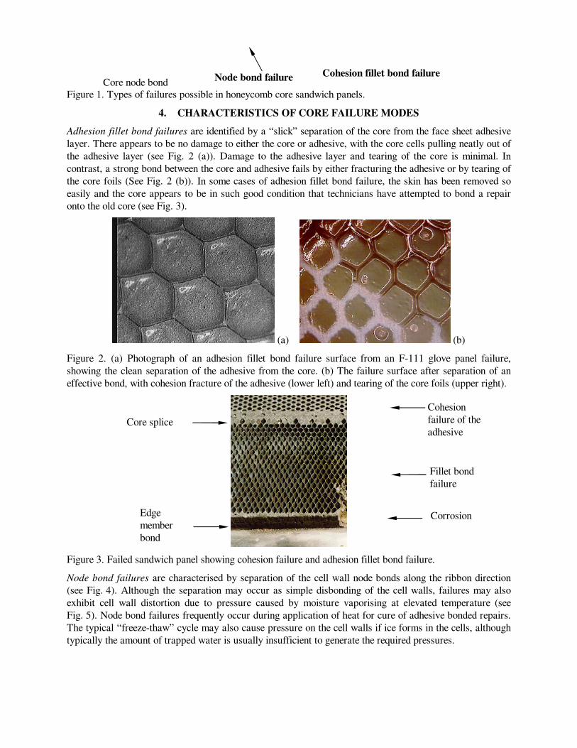
Figure 1. Types of failures possible in honeycomb core sandwich panels.
4. CHARACTERISTICS OF CORE FAILURE MODES
Adhesion fillet bond failures are identified by a “slick” separation of the core from the face sheet adhesive
layer. There appears to be no damage to either the core or adhesive, with the core cells pulling neatly out of
the adhesive layer (see Fig. 2 (a)). Damage to the adhesive layer and tearing of the core is minimal. In
contrast, a strong bond between the core and adhesive fails by either fracturing the adhesive or by tearing of
the core foils (See Fig. 2 (b)). In some cases of adhesion fillet bond failure, the skin has been removed so
easily and the core appears to be in such good condition that technicians have attempted to bond a repair
onto the old core (see Fig. 3).
(a) (b)
Figure 2. (a) Photograph of an adhesion fillet bond failure surface from an F-111 glove panel failure,
showing the clean separation of the adhesive from the core. (b) The failure surface after separation of an
effective bond, with cohesion fracture of the adhesive (lower left) and tearing of the core foils (upper right).
Figure 3. Failed sandwich panel showing cohesion failure and adhesion fillet bond failure.
Node bond failures are characterised by separation of the cell wall node bonds along the ribbon direction
(see Fig. 4). Although the separation may occur as simple disbonding of the cell walls, failures may also
exhibit cell wall distortion due to pressure caused by moisture vaporising at elevated temperature (see
Fig. 5). Node bond failures frequently occur during application of heat for cure of adhesive bonded repairs.
The typical “freeze-thaw” cycle may also cause pressure on the cell walls if ice forms in the cells, although
typically the amount of trapped water is usually insufficient to generate the required pressures.
Node bond failure
Cohesion
failure of the
adhesive
Core node bond
Fillet bond
failure
Cohesion fillet bond failure
Corrosion
Core splice
Edge
member
bond

5. CREDP EXPERIENCE WITH IN-SERVICE FAILURES
A number of in-flight failures have occurred due to adhesion fillet or node bond failures, resulting in severe
damage and/or loss of control surfaces and structural panels on USN F/A-18. After the USN raised the
issue of such damage mechanisms causing structural failures, a review of defect reports from other CREDP
member fleets also identified the characteristics of these failures. Investigation of one failed F/A-18
graphite/epoxy skinned rudder (Fig. 6) shows that on a significant proportion of the failed surface there is
minimal core fracture and negligible damage occurring to adhesive which was still bonded to the inner
surface of the face sheet. Areas A and B show complete adhesion failure while areas C and D exhibits
evidence of mixed cohesion and adhesion failures. The absence of adhesive on the ends of the core cells and
the absence of fractured core are indicative of adhesion fillet bond failure. In contrast, the adjacent area (E)
displays a typical cohesion peel failure, with fractured adhesive left on the cells.
Figure 4. Node bond failures in aluminium core,
showing the separation of the cell node bonds
along the ribbon direction after exposure to slow
cycle fatigue at a hot-wet tropical site.
Figure 5. Node bond failure and cell wall
distortion at “A” caused by internal pressure in
aluminium core.
Figure 6. Photograph of a failed F/A-18 composite skinned rudder. A and B show complete adhesion failure
while areas C and D exhibit evidence of mixed cohesion and adhesion failures, and peel failure (E). Note
that protective tape has been applied for safer handling.
A
B
D
C
E
A

The RAAF has also experienced core adhesion fillet bond failures on a fixed glove panel on F-111 (see
Fig. 7). This defect became apparent when the inner skin separated from the core region during an attempt
to perform a hot-bonded repair in the adjacent panel bay. The figure shows light corrosion around previous
injection repairs (A) and a large area of adhesion fillet bond failure (B), where the skin simply lifted off the
core. Less than 10% of the panel exhibited a cohesion peel failure through the adhesive (C) during break-
down for rebuild. All of the remaining panels on this component displayed similar fillet bond degradation.
Figure 7. An F-111 fixed glove sandwich panel showing light corrosion at injection repairs (A), adhesion
fillet bond failure (B) which occurred in service and peel failure (C) caused during break-down of the panel
for rebuild.
Fillet bond failure is visible on the surface of an F-111 over-wing fairing recovered after an in-flight failure
(Fig. 8). The adhesive shown on the surface is from injection “repairs”. Note also that the cast impression at
“A” of the matching bonding surface clearly show the core pattern. This indicates that the original defect,
prior to injection repair was adhesion fillet bond failure. This large panel separated in flight causing
extensive damage to the fin leading edge, rudder, horizontal stabilator and fuselage. In another USN in-
flight failure, a trailing-edge flap upper-skin separated adjacent to a large repair. Core adhesion fillet bond
failures were observed in conjunction with widespread node bond failures.
A
B
C
C

Figure 8. Failure surface from a recovered section of an F-111 over-wing fairing lost in flight.
Off-aircraft failures have been noted by the USN and RAAF during repair heating procedures to sandwich
panels with both composite and aluminium skins. Under elevated temperature, the cell pressure increases
due to the expansion of the air. Free moisture in the cells, or moisture which is de-sorbed from the adhesive
or composite skins also greatly increases the pressure as the water turns to steam. Extensive measures have
been undertaken to dry panels before heating above 100°C (250°F), with the USN experiencing failures
even after a 48 hour drying cycle. The core pressure either forces the face sheet to disbond by adhesion fillet
bond failure, or forces the cell wall bonds apart in a node bond failure. Similar panel damage has occurred
on repairs on RAAF F-111. Failures are not restricted to older panels. The USN has experienced damage to
sandwich structure on F/A-18 D model aircraft with less than five years service. Hence the degradation
appears to be related more to service exposure time and high humidity environments than flight hours.
The USN has attempted to use lower temperature curing adhesive systems in order to minimise the pressure
build up. By use of a 250°F curing adhesive, the cell pressure during repair has been reduced below the
FWT strength of the fillet bonds. While this approach has eliminated adhesion fillet bond failures, node
bond failures have still occurred. So far, the USN has experienced damage to two trailing edge flaps, a
rudder and a number of horizontal stabilators. More extensive damage has occurred in panels which have
been repaired by use of an autoclave, due to heating of the entire panel which may cause node bond failures
at other sites where undetected moisture is present, with damage occurring over a metre from the repair site.
The USN now perform 100% X-Ray on all autoclave repaired panels, and X-Ray a region of at least 12
inches around any site heated for local repair cure.
6. CIVIL AVIATION EXPERIENCE
There is evidence of similar failure modes on civil aircraft, although there is no clear identification of the
damage types. The FAA has issued an Airworthiness Directive AD 90-12-13 for the inspection of Airbus
A310 rudders for disbonds, with the description of the problem being very similar to that experienced by the
CREDP members. Inspection of Airbus elevators from one Australian civil airline revealed skin-to-core
disbonds which when investigated under a low power microscope revealed core node and adhesion fillet
bond failures. Concerns were expressed by the airline when the size of a disbond identified using the
recommended NDI procedures was found to be less than 20% of the actual size of the core fillet bond
failure found during damage removal. A later draft AD to update disbond inspection procedures was issued
under Rules Docket No. 96-NM-65-AD. These Airbus elevators are fabricated with graphite/epoxy skins
on Nomex core. Elevator core samples were inspected by the RAAF and found to have similar failure
modes to those experienced in aluminium cored sandwich panels (see Fig. 9).
A

7. FAILURE INVESTIGATIONS
Post failure analysis has revealed that the node bond adhesive from at least one core supplier is applied to
the aluminium during manufacture of the core as a series of discrete dots rather than as a continuous film
(see Fig. 10). Should the cell wall node bonds not form a complete cover, leaving gaps in the core adhesive,
these gaps would increase the rate of moisture progression through a sandwich panel. Node bond failures on
one particular brand of core, although appearing to be adhesion node bond failures, are in fact cohesion
failures. Optical and electron microscopical examinations have revealed the presence of adhesive on both
failure surfaces (see Fig. 11). On other core material, node bond adhesive is peeling from the surface
interfacially. Aeronautical and Maritime Research Laboratories (AMRL) (Melbourne) showed that the
different forms of failure correlate with two core manufacturing companies. The manufacturers use
different core node bond adhesives, and one appears to have a lower durability than the other. Different
surface preparation procedures prior to bonding the foils together may also contribute to the interfacial
failure mode.
Figure 9. Adhesion fillet bond failures in
Nomex core from an Airbus elevator.
Figure 10. Magnified view of an adhesive strip
used to bond the foils together at the nodes.
(a) (b)
Figure 11. Close-up photograph of a core node bond region taken from the F-111 glove panel. Note the core
node bond adhesive peeling off the surface of the cell walls. The magnified region in Fig. (b) shows the
presence of what appears to be residual adhesive on the core surface.
Observations by the RAAF indicate that adhesion fillet bond degradation is typically interfacial (see
Fig. 12). The shiny appearance of the fillet bond region of the core foils suggests the region had been

experiencing fretting abrasion due to relative movement between the core foil and the adhesive on the face
sheet. Such interfacial (adhesion) failures are usually associated with bonding surfaces with a low resistance
to hydration [2]. This appears likely with the fillet bond because there is no available method for
preparation of core material prior to bonding to the face sheet adhesive (apart from solvent cleaning which
does not affect the oxide layer). The inadequately prepared surface will be susceptible to hydration of the
chemical bonds between the metallic surface and the adhesive.
In a significant number of honeycomb panel failures there is a moisture entry path adjacent to the defective
area which, as well as causing the core bond degradation problems discussed, may also cause corrosion.
Two failed F/A-18 rudders exhibited corrosion or the presence of water which had entered through a poorly
sealed fasteners. In Canada, Bombardier has found a extensive corrosion in metal faced sandwich structure
on CL-41 Tutor aircraft. Similar corrosion frequently occurs on RAAF F-111. In many cases a breakdown
of the panel sealing leads to the moisture entry.
Figure 12. Photograph of a honeycomb core foil showing light surface corrosion which does not extend into
the fillet bond area (top of photograph).
Many of the metal faced RAAF F-111 sandwich panels which exhibited core corrosion and core and node
bond failures had been “repaired” using adhesive injection procedures or potted repairs. Injection repairs
attempt to rebond disbonded face sheets by squeezing fresh liquid adhesive into disbonds. Because the
surfaces which have disbonded are no longer chemically suited to adhesion, this form of repair has very
little success. Moisture may then enter the sandwich panel through the injection holes. In potted repairs,
disbonded skin material is cut away and core removed. The cavity is then filled with a resin and glass flock
mixture. In the past there was no requirement to cover injection or potted repairs with a moisture barrier
and consequently, moisture entered panels by diffusing through the potting material.
8. STRUCTURAL INTEGRITY IMPLICATIONS AND ASSOCIATED RESEARCH
The USN (NADEP-NI) have tested core node bonds by cutting individual nodes from core sections and then
performing a micro T-peel test. Node bond T-peel specimens were cut from a sample of Hexcell CRIII core
and exposed to 60°C (140°F) at 95% RH in a humidity cabinet. After 6 weeks of exposure specimens
exhibited a loss of strength from a baseline value of 6.2 pounds per inch width (piw) to 4.2 piw and began
to exhibit an adhesion failure mode. For specimens cut from failed node bond areas on repaired parts T-peel
strengths were reduced to approximately 1 piw. Fillet bonds have experienced similar reductions in strength
following moisture exposure. Climbing drum peel tests after exposure to 35°C (95°F) and 95% RH for over
20 months by the CF [3], exhibited a significant loss of strength and a change from cohesion to adhesion
fillet bond failure. The USN (NADEP-NI) have also shown a similar loss in FWT strength for specimens
subjected to a 7 day exposure to boiling water [4]. Such substantial losses in strength, combined with a

history of in-flight losses of components, suggests that there is a risk to structural integrity of aircraft
components from these forms of defects. Safety-of-flight will depend upon the criticality of the individual
component, flight loads and the extent of damage.
Despite the prevalence of honeycomb degradation in aircraft honeycomb panels and the possible effect this
could have on the structural integrity of the aircraft, there appears to be little in the literature on systematic
studies of the effect of such degradation on the structural integrity of sandwich panels.
In Canada, as part of CREDP, Canadair are preparing to develop a computer model that will look at the
effects of reduced FWT strength on structural integrity of honeycomb sandwich assemblies. They are
planning on using input values based on the “wet” FWT test data generated experimentally as well as test
data derived using a “Porta-Pull” device used to measure the tension load necessary to pull a sandwich
panel face sheet from the core. Boeing St. Louis has undertaken to review the implications for structural
integrity of a reduction in FWT strength to the levels detected on the basis of the available test data.
In Australia, AMRL plan to study the effect of sandwich panel defects on F-111 structural integrity by use
of a specimen representative of typical aircraft structure to validate a Finite Element (FE) model of the
aircraft. The flight loads required to cause skin or fillet bond failure will then be able to be calculated and
measured for different initial defect sizes. Finally using a global/local FE model, the influence of a local
failure will be investigated by examining the way in which load is shed into adjacent structure. The effect of
this load increase will be evaluated to see if further failures in neighbouring structures could be expected.
This information will enable an assessment of the significance of honeycomb defects and will assist in
establishing maximum tolerable defect sizes for inspection requirements.
9. SUPPORTING RESEARCH
The USN (NADEP-NI) and AMRL have undertaken programs to develop methods of conducting rapid tests
to produce the failure modes detected on aircraft components. The principal aim of these programs is to
develop a relatively quick test (compared to actual service exposure) which can be used to evaluate different
materials or processes. The program will attempt to correlate a reduction in FWT strength (which is not a
design number) with a reduction in beam shear strength (which is a design number).
The need for these programs to develop such a test is significant because a limiting factor in studying
adhesion fillet bond failure is the ability to reproduce the failure modes under laboratory conditions. Simple
approaches using release agents and sprays to simulate adhesion fillet bond failures do not produce
acceptable fillets due to the hydrophobic nature of the core surface. The only reliable fillet reproduction
method found so far is to form the fillets as a normal bond and then to expose the specimen to a high
humidity environment. To reduce environmental exposure times prior to testing, AMRL are evaluating two
methods for moisturising specimens. For metallic-skinned specimens, only one skin is bonded to the core
initially and the specimen exposed to the hot/wet environment in this state. After drying to remove excess
water, the bare core surface is bonded directly to the load block for testing. This test configuration gives a
slightly stiffer specimen than one with two skins and initial results for non-degraded specimens indicate that
failure loads are higher (11.7MPa) than comparable double skinned specimens (9.6 MPa).
For composite skinned specimens, the graphite/epoxy laminates have been drilled with a diamond coated
drill to create approximately 100 holes in each 2500 mm2 face sheet. This is to enable moisture to rapidly
degrade the interior of the structure during the hot/wet exposure. An obvious difference between composite
and metal face sheets is that moisture can diffuse through the composite skin over time, whereas for the
metal skin, moisture can only gain access to the interior of the structure through a leakage point. To
investigate possible differences in the failure modes, some of the composite skinned specimens will not be
drilled and the moisture will be forced to diffuse through the face sheets to attack the fillet and node bonds.
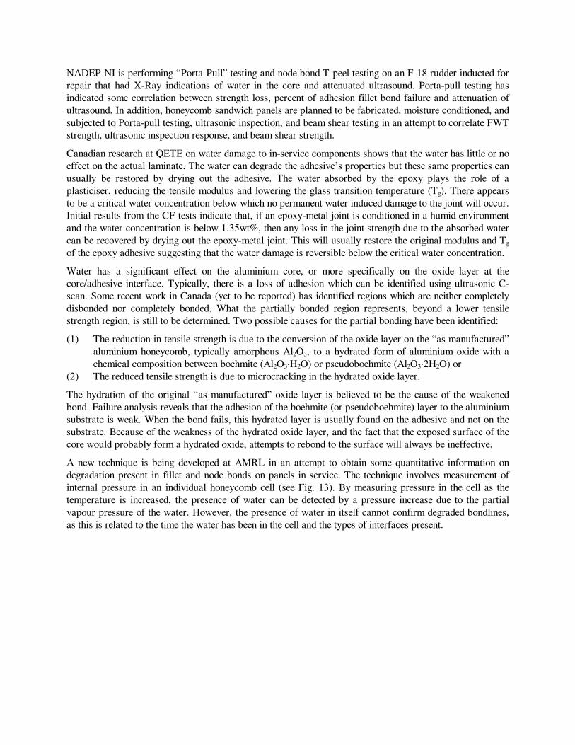
NADEP-NI is performing “Porta-Pull” testing and node bond T-peel testing on an F-18 rudder inducted for
repair that had X-Ray indications of water in the core and attenuated ultrasound. Porta-pull testing has
indicated some correlation between strength loss, percent of adhesion fillet bond failure and attenuation of
ultrasound. In addition, honeycomb sandwich panels are planned to be fabricated, moisture conditioned, and
subjected to Porta-pull testing, ultrasonic inspection, and beam shear testing in an attempt to correlate FWT
strength, ultrasonic inspection response, and beam shear strength.
Canadian research at QETE on water damage to in-service components shows that the water has little or no
effect on the actual laminate. The water can degrade the adhesive’s properties but these same properties can
usually be restored by drying out the adhesive. The water absorbed by the epoxy plays the role of a
plasticiser, reducing the tensile modulus and lowering the glass transition temperature (Tg). There appears
to be a critical water concentration below which no permanent water induced damage to the joint will occur.
Initial results from the CF tests indicate that, if an epoxy-metal joint is conditioned in a humid environment
and the water concentration is below 1.35wt%, then any loss in the joint strength due to the absorbed water
can be recovered by drying out the epoxy-metal joint. This will usually restore the original modulus and Tg
of the epoxy adhesive suggesting that the water damage is reversible below the critical water concentration.
Water has a significant effect on the aluminium core, or more specifically on the oxide layer at the
core/adhesive interface. Typically, there is a loss of adhesion which can be identified using ultrasonic C-
scan. Some recent work in Canada (yet to be reported) has identified regions which are neither completely
disbonded nor completely bonded. What the partially bonded region represents, beyond a lower tensile
strength region, is still to be determined. Two possible causes for the partial bonding have been identified:
(1) The reduction in tensile strength is due to the conversion of the oxide layer on the “as manufactured”
aluminium honeycomb, typically amorphous Al2O3, to a hydrated form of aluminium oxide with a
chemical composition between boehmite (Al2O3·H2O) or pseudoboehmite (Al2O3·2H2O) or
(2) The reduced tensile strength is due to microcracking in the hydrated oxide layer.
The hydration of the original “as manufactured” oxide layer is believed to be the cause of the weakened
bond. Failure analysis reveals that the adhesion of the boehmite (or pseudoboehmite) layer to the aluminium
substrate is weak. When the bond fails, this hydrated layer is usually found on the adhesive and not on the
substrate. Because of the weakness of the hydrated oxide layer, and the fact that the exposed surface of the
core would probably form a hydrated oxide, attempts to rebond to the surface will always be ineffective.
A new technique is being developed at AMRL in an attempt to obtain some quantitative information on
degradation present in fillet and node bonds on panels in service. The technique involves measurement of
internal pressure in an individual honeycomb cell (see Fig. 13). By measuring pressure in the cell as the
temperature is increased, the presence of water can be detected by a pressure increase due to the partial
vapour pressure of the water. However, the presence of water in itself cannot confirm degraded bondlines,
as this is related to the time the water has been in the cell and the types of interfaces present.

Figure 13. The gas injection tube system, pressure sensor and needle valve for pressure regulation used to
detect moisture and to determine cell node bond strength.
A second measurement techniques is being investigated to obtain information as to the degree of bondline
degradation. Using the same equipment, the temperature is kept constant, and pressure is increased by
injecting nitrogen gas into the cell, creating a mode 1 stress in the node bond joints of that cell. If the joints
are not degraded, the pressure should continue to rise as nitrogen is admitted until the cell fails at a high
pressure (dependent on the type of core and adhesive). A sudden drop in pressure at an early stage indicates
that the node bond was degraded and has failed, allowing gas to escape into neighbouring cells. This result
would suggest that core replacement may be required together with an investigation to determine how the
moisture entered the core. However, this technique involves drilling a small hole in the skin and so is not
strictly speaking a non-destructive technique. The damage involved is however very minor, although it will
be important to ensure that the hole can be effectively sealed to prevent future water ingress.
10. NON-DESTRUCTIVE INSPECTION
Extensive NDI examinations of scrap honeycomb components from both F-111 and F/A-18 aircraft are
being correlated with destructive investigations to determine the exact nature of the failures detected. This
will enable determination of the resolution and accuracy of various NDI methods used. Results to date
indicate that NDI methods such as X-Ray radiography and conventional ultrasonics are only capable of
detecting severe damage to either fillet or node bonds. These techniques have also been successful in
detecting deliberate defects in a calibration test panel such as artificial disbonds or cut nodes.
Both conventional and innovative inspection methods are being tried to see if it is possible to detect the early
onset of disbonding of degraded honeycomb structures. Thermography, ultrasonics and X-Ray radiography
have all been tried on both degraded components as well as NDI standard specimens. Good results have
been obtained with some of the more conventional techniques as well as newer methods such as ELCH
(Elasticity Laminate CHecker) and the Bondmaster instrument, although the key lesson learned is that no
one technique applies equally well to all defect types. Because of the need to obtain a vacuum seal, the
ELCH was found to have limited practical application for panels with even moderate curvature. In the short
to medium term, it is clear that a range of NDI methods will be required to obtain good quality information
from a range of different damage types.

With adhesion fillet bond failures, while the interface between the adhesive and the core at the fillet may be
weak, sufficient contact remains to enable transmission of sound and so precludes the use of simple
ultrasonic inspection techniques and the coin-tap test. Extensive fillet bond failures become easier to detect
using simple techniques after the core has separated from the adhesive on the face sheets. The RAAF is
investigating the use of laser holography to inspect for reduced core fillet bond stiffness, which may enable
identification of potentially defective surfaces. Research at QETE in Canada has developed an optimised
ultrasonic C-scan through-transmission method. The technique appears to be capable of finding disbonds as
well as partial bonding. It has identified regions on an F/A-18 rudder which are different from the obvious
disbonds and good portions of the rudder. Tests have confirmed these regions as having lower tensile
strengths through the use of the “Port-a-Pull” testing equipment. The CF have also found moisture
degradation during an N-Ray examination of a composite rudder. The USN (NADEP-NI) have also had
some success using ultrasonic C-scan to identify areas of partial fillet bonds on an F-18 rudder. The cause
of the signal attenuation is unknown, but in those areas where the C-scan indicates about 80-90%
attenuation, “Porta-Pull” tests show a large loss of strength (to approximately 80 psi compared to the
minimum value of 625 psi) and an adhesion fillet bond failure. Adjacent to the indication (in an
"acceptable" area by C-scan) “Porta-Pull” strengths are near 600 psi and 5% adhesion/95% cohesion fillet
bond failures are observed.
Detection of node bond failures is relatively easy using X-Ray, provided the core cell walls have been
distorted by pressure during heating procedures. However X-Ray examinations are slow and expensive, and
not all node bond failures cause cell wall distortion.
11. COMPONENT MANAGEMENT
Localised repairs using high temperature curing adhesives may be relatively ineffective, depending on the
extent of degradation and the pressures generated during such cure cycles. Localised high temperature
repairs may cause more significant damage than the defect being repaired, due to the low bond strength of
the nodes and fillets near the defective region. Where possible, lower temperature curing adhesives should
be used for repair to reduce the build up of internal pressures during heating to the cure temperatures.
If moisture continues to degrade the core node and fillet bonds, the FWT strength will eventually degrade to
zero, resulting in a loss of panel integrity and also making repair impossible. An obvious measure for
reduction of the occurrences of adhesion fillet and node bond failures in existing panels is to pay particular
attention to sealing moisture entry paths. Epoxy based fillers should not be used for this purpose due to the
moisture adsorption characteristics of these materials.
NADEP (NI), Boeing St Louis and Naval Air Warfare Centre (NAWC) Patuxent River are investigating
the use of Phosphoric Acid Anodised (PAA) core for use on the F/A-18E/F as well as for production of
current model F/A-18 spares. Comparison testing is under way between standard core and PAA core to
evaluate fatigue response as well as fillet bond strength, node bond T-peel strength and core delamination
strength following environmental exposure. Testing should be completed by mid 1999. Published data [5]
suggests that PAA core performs significantly better than conventional core materials under hot-wet
exposure.
12. CONCLUSIONS
The problem of fillet and node bond degradation in honeycomb sandwich panels appears to be widespread
and has structural integrity implications. The consequences to flight safety will need to be evaluated for
each individual component. Existing NDI techniques appear to be adequate for detection of large area
disbonds and some recently developed methods show promise for development of effective inspection
measures for service components. One short term measure for prevention of these defect types is to ensure
all moisture entry paths are adequately sealed. Longer term, the use of PAA core may present the best
method for prevention of core degradation problems.
The objective of this paper is to alert the aviation industry to the nature and significance of adhesion fillet
and node bond core degradation problems, and to seek industry input on inspection techniques, structural
integrity assessment, and procedures for repair and prevention. The authors would welcome discussion.
ACKNOWLEDGMENTS
The nominated authors readily acknowledge that this paper is a summary of a significant amount of work
by a number of other individuals who have contributed substantially to the advancement of understanding of
the adhesion fillet and node bond problems. Particular mention is made of the contributions by:
Australia: Dr. Alan Baker, Dr. David Arnott, Dr. Christine Scala, Mr. Peter Pearce, FLTLT David Bond.
Canada: Claude Lelievre, Sgt. Michel Montambeault.
USA: Peggy Williams, Mr. Kurt Gaenzle, Dr. Alex Rubin (Boeing St. Louis).
REFERENCES:
1. USN NADEP-NI/MEL Rpt 296051 dated 12 Mar 96
2. Kinlock, A.J., Adhesion and Adhesives, p 78, Chapman and Hall, 1987.
3. A. J. Russell and J. S. Ferguson, Composite Repair Issues On the CF-18 Aircraft, 79th Meeting of the
AGARD Structures and Materials Panel, October 1994
4. D. R. Perl, Evaluation of Damage to F/A-18 Advanced Composite Honeycomb Sandwich Parts
Caused by Elevated Temperature Cure Cycles, 39th Int. SAMPE Symp. and Exhibition, April 1994
5. Olivo, K.G., PAA Core Aluminum Honeycomb: An End User’s Evaluation, 37th Int. SAMPE Symp.
Mar 9-12, 1992, pp 198-206.