Embed Size (px)
Citation preview
1
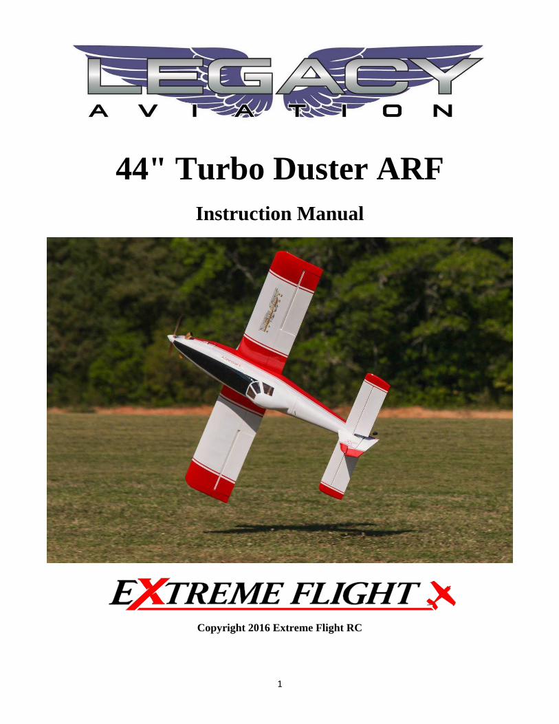
44" Turbo Duster ARF
Instruction Manual
Copyright 2016 Extreme Flight RC
2
Please take a few moments to read this instruction manual before beginning assembly. We have outlined a fast, clear and easy method to assemble this aircraft and familiarizing yourself with this process will aid in a quick, easy build.
Please read the following paragraph before beginning assembly of your aircraft! THIS IS NOT A TOY! Serious injury, destruction of property, or even death may result from the misuse of this product. Extreme Flight RC is providing you, the consumer, with a very high quality model aircraft component kit, from which you, the consumer, will assemble a flying model. It is beyond our control to monitor the finished aircraft you produce. Extreme Flight RC will in no way accept or assume responsibility or liability for damages resulting from the use of this user assembled product. This aircraft should be flown in accordance with the AMA safety code. It is highly recommended that you join the Academy of Model Aeronautics in order to be properly insured and operate your model at AMA sanctioned flying fields only. If you are not willing to accept ALL liability for the use of this product, please return it to the place of purchase immediately. Extreme Flight RC, Ltd. guarantees this kit to be free of defects in materials and workmanship for a period of 30 DAYS from the date of purchase. All warranty claims must be accompanied by the original dated receipt. This warranty is extended to the original purchaser of the aircraft kit only. Extreme Flight RC in no way warranties its aircraft against flutter. We have put these aircraft through the most grueling flight tests imaginable and have not experienced any control surface flutter. Proper servo selection and linkage set-up is absolutely essential. Inadequate servos or improper linkage set up may result in flutter and possibly the complete destruction of your aircraft. If you are not experienced in this type of linkage setup or have questions regarding servo choices, please contact us at [email protected] or 770-887-1794. It is your responsibility to ensure the airworthiness of your model.
3
Congratulations on your purchase of the Legacy Aviation 44" Turbo Duster ARF!
We've all stopped on the side of the road to watch cropdusters at work. Practical aerobatics combined with real precision flying makes it very cool to see. The 44" Turbo Duster captures the spirit of the latest-technology full-scale dusters.
The Turbo Duster ARF is quick to build, strong, light, and is very high-performance. In addition to all of the low-level scale maneuvers, you can take the Duster to the extremes of high-energy tumbling aerobatics, or you can fly it as a gentle and predictable sport airplane – it's up to you!
The Duster uses simple, inexpensive equipment, such as a 100g outrunner motor, 3S 2200 lipo, and 6 micro servos. The flaps can (and should!) be programmed for a variety of fun modes, to give an extra-wide flight envelope. The Duster is going to delight you with its many talents – so let's get started!
Items needed for completion:
Masking tape. Hobby knife with #11 blades. Thin and medium or thick CA. 30 minute epoxy. Blue Loctite. Electric drill with an assortment of small drill bits. Small flat head and Phillips head screw drivers. Standard and needle nose pliers. Side cutter. Metric ball driver or allen key set. Sanding stick or sandpaper. Rubbing alcohol. 6 x micro servo. All flight testing was carried out on MKS HV6100. 2 x 6” Servo Extensions for the Ailerons. 2 x 12” Servo Extensions for the rudder and elevator servos Omega 103g brushless outrunner or other motor 90-120grams
weight. Airboss Elite 45 Amp ESC. 3S 1800-2500 mah LiPo battery. 11x5.5 - 12x6 prop.
4
Tips for Success:
1. Before starting assembly, take a few minutes to read the entire instruction manual to familiarize yourself with the assembly process.
2. Please take a few minutes and go over all the seams on the aircraft with a covering
iron on a medium heat setting. Also, due to climate changes, wrinkles may develop in the covering. These are easily removed with a little bit of heat. Use a 100% cotton tee-shirt and your heat gun and heat the covering while gently rubbing the covering onto the wood with the t-shirt. Be careful not to use too much heat as the covering may shrink too much and begin to lift at the edges. Take your time, and a beautiful, paint-like finish is attainable.
3. Apply a bead of Pacer Formula 560 Canopy Glue at the intersection of the plastic canopy and its wooden frame.
4. Take a few minutes and apply CA to high stress areas such as servo mounting trays,
landing gear mounts, anti-rotation pins, and motor box joints.
5. By the time your aircraft arrives at your door step, it will have been handled by a lot of people. Occasionally, there are small dings or imperfections on some of the surfaces. An effective method to restore these imperfections to original condition is to use a very fine tipped hypodermic needle and inject a drop of water under the covering material and into the ding in the wood. Apply heat to the area with a sealing iron and the imperfection will disappear. Deeper marks may require that this process be repeated a couple of times to achieve the desired result, but you will be surprised at how well this technique works.
6. Use a high quality epoxy for installing the composite control horns. We highly
recommend the new Mercury Adhesives 30 minute Epoxy or Pacer Z-poxy. We are very pleased with the results and ease of application and cleanup of these products.
7. When applying decals, first clean the area where the decal will be applied with
alcohol. Mist the area lightly with Windex or Rapid Tack before applying the decal which will allow you to properly position it, and then use a rubber squeegee to push all of the liquid from under the decal. This will result in very few air pockets trapped under the decal.
8. Take the time to properly balance and trim your aircraft and set up rates and
exponential values. Your flying experience will be greatly enhanced once your plane is properly dialed in.
5
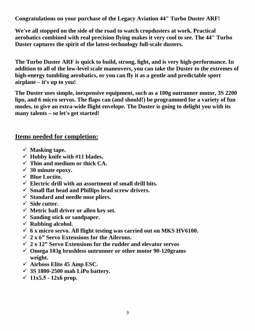
Let's begin!
1. Locate the cowl and exhaust stacks as shown.
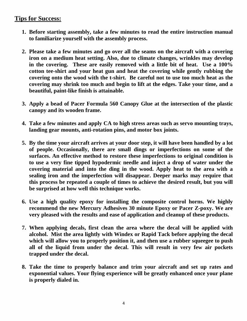
Using sandpaper, rough up the mounting surface of the stack and the cowl.
6
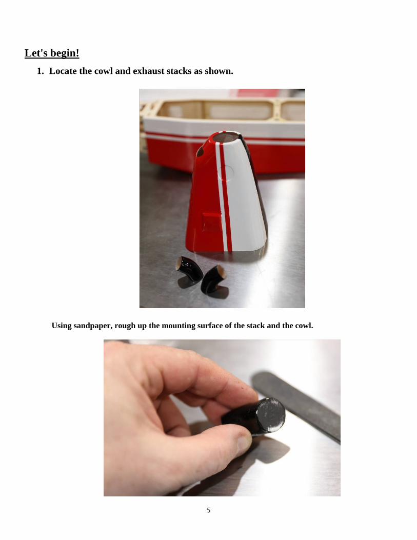
Glue the stacks to the cowl with epoxy or rubber cement, using masking tape to hold them while drying.
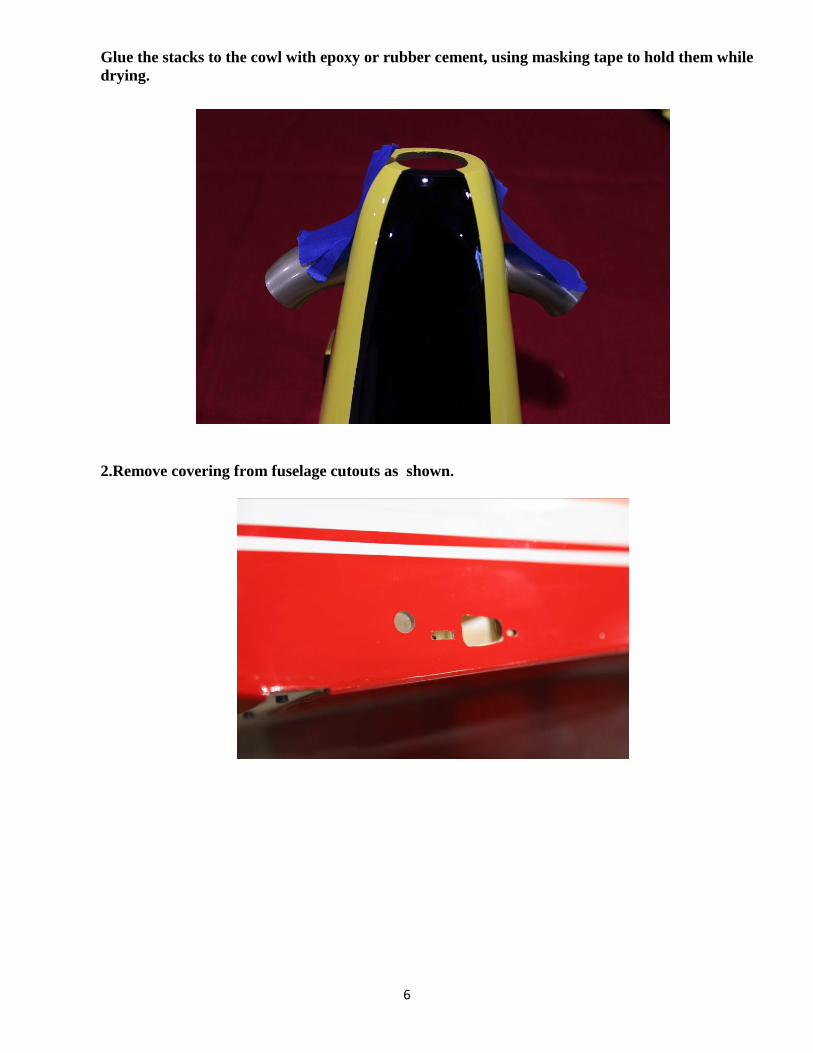
2.Remove covering from fuselage cutouts as shown.
7
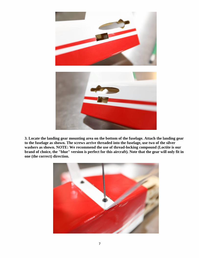
3. Locate the landing gear mounting area on the bottom of the fuselage. Attach the landing gear to the fuselage as shown. The screws arrive threaded into the fuselage, use two of the silver washers as shown. NOTE: We recommend the use of thread-locking compound (Loctite is our brand of choice, the "blue" version is perfect for this aircraft). Note that the gear will only fit in one (the correct) direction.
8
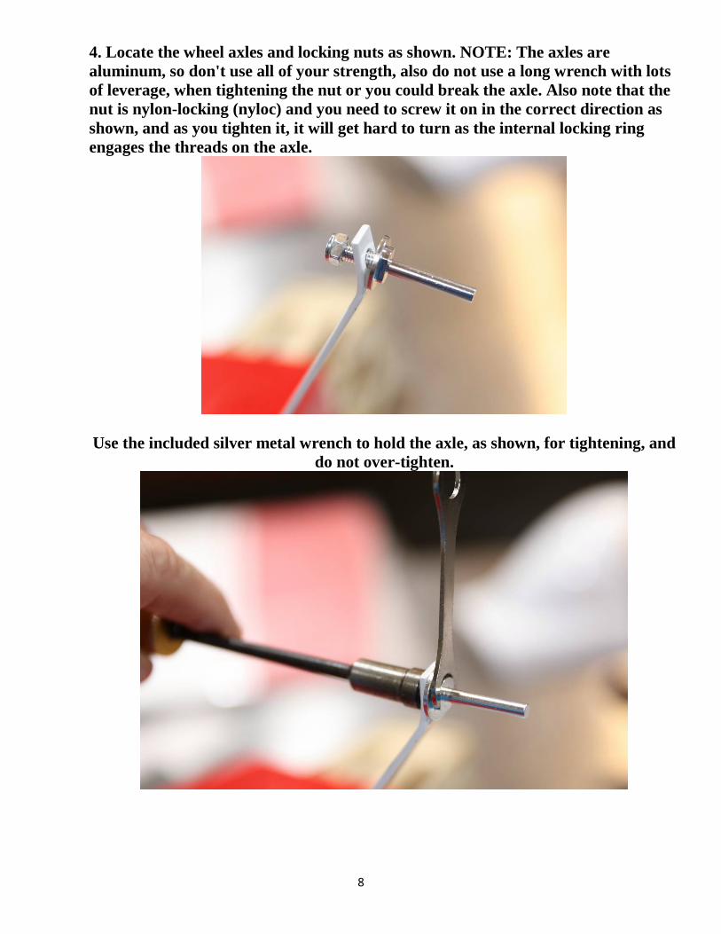
4. Locate the wheel axles and locking nuts as shown. NOTE: The axles are aluminum, so don't use all of your strength, also do not use a long wrench with lots of leverage, when tightening the nut or you could break the axle. Also note that the nut is nylon-locking (nyloc) and you need to screw it on in the correct direction as shown, and as you tighten it, it will get hard to turn as the internal locking ring engages the threads on the axle.
Use the included silver metal wrench to hold the axle, as shown, for tightening, and do not over-tighten.
9
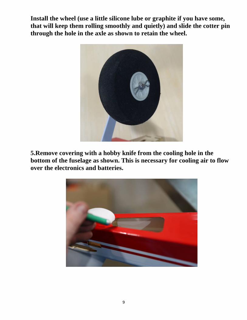
Install the wheel (use a little silicone lube or graphite if you have some, that will keep them rolling smoothly and quietly) and slide the cotter pin through the hole in the axle as shown to retain the wheel.
5.Remove covering with a hobby knife from the cooling hole in the bottom of the fuselage as shown. This is necessary for cooling air to flow over the electronics and batteries.
10
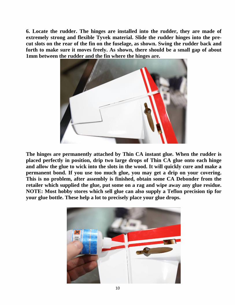
6. Locate the rudder. The hinges are installed into the rudder, they are made of extremely strong and flexible Tyvek material. Slide the rudder hinges into the pre-cut slots on the rear of the fin on the fuselage, as shown. Swing the rudder back and forth to make sure it moves freely. As shown, there should be a small gap of about 1mm between the rudder and the fin where the hinges are.
The hinges are permanently attached by Thin CA instant glue. When the rudder is placed perfectly in position, drip two large drops of Thin CA glue onto each hinge and allow the glue to wick into the slots in the wood. It will quickly cure and make a permanent bond. If you use too much glue, you may get a drip on your covering. This is no problem, after assembly is finished, obtain some CA Debonder from the retailer which supplied the glue, put some on a rag and wipe away any glue residue. NOTE: Most hobby stores which sell glue can also supply a Teflon precision tip for your glue bottle. These help a lot to precisely place your glue drops.
11
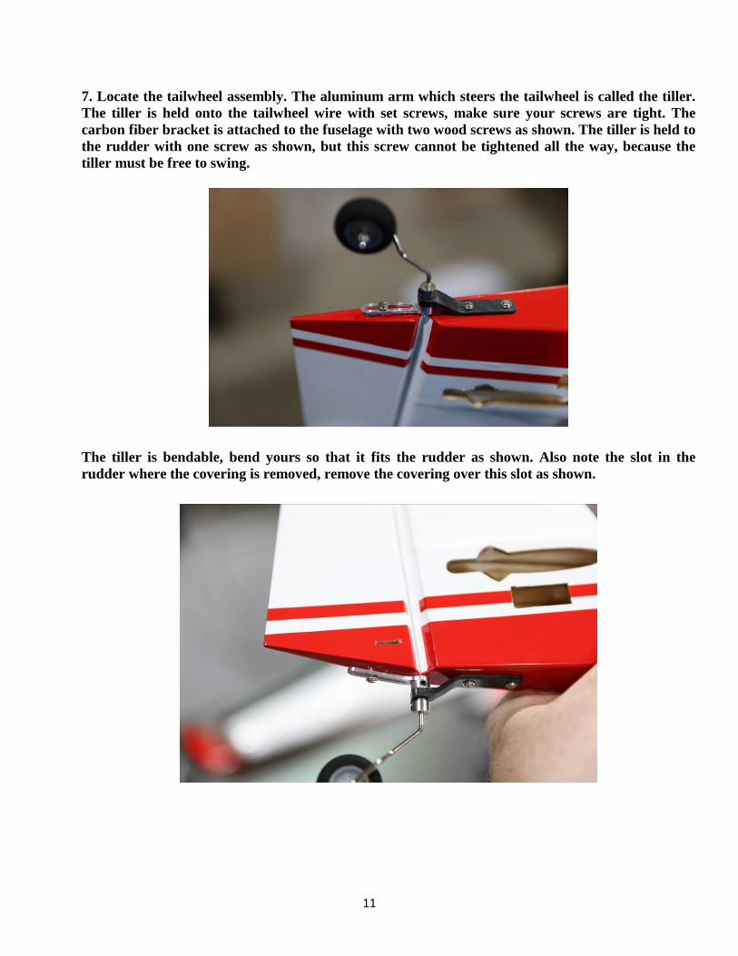
7. Locate the tailwheel assembly. The aluminum arm which steers the tailwheel is called the tiller. The tiller is held onto the tailwheel wire with set screws, make sure your screws are tight. The carbon fiber bracket is attached to the fuselage with two wood screws as shown. The tiller is held to the rudder with one screw as shown, but this screw cannot be tightened all the way, because the tiller must be free to swing.
The tiller is bendable, bend yours so that it fits the rudder as shown. Also note the slot in the rudder where the covering is removed, remove the covering over this slot as shown.
12
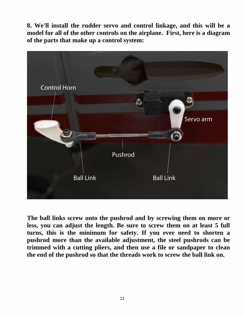
8. We'll install the rudder servo and control linkage, and this will be a model for all of the other controls on the airplane. First, here is a diagram of the parts that make up a control system:
The ball links screw onto the pushrod and by screwing them on more or less, you can adjust the length. Be sure to screw them on at least 5 full turns, this is the minimum for safety. If you ever need to shorten a pushrod more than the available adjustment, the steel pushrods can be trimmed with a cutting pliers, and then use a file or sandpaper to clean the end of the pushrod so that the threads work to screw the ball link on.
13
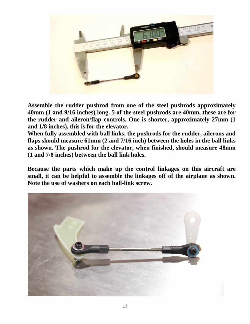
Assemble the rudder pushrod from one of the steel pushrods approximately 40mm (1 and 9/16 inches) long. 5 of the steel pushrods are 40mm, these are for the rudder and aileron/flap controls. One is shorter, approximately 27mm (1 and 1/8 inches), this is for the elevator. When fully assembled with ball links, the pushrods for the rudder, ailerons and flaps should measure 61mm (2 and 7/16 inch) between the holes in the ball links as shown. The pushrod for the elevator, when finished, should measure 48mm (1 and 7/8 inches) between the ball link holes. Because the parts which make up the control linkages on this aircraft are small, it can be helpful to assemble the linkages off of the airplane as shown. Note the use of washers on each ball-link screw.
14
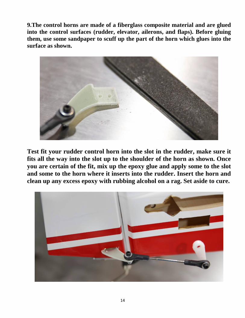
9.The control horns are made of a fiberglass composite material and are glued into the control surfaces (rudder, elevator, ailerons, and flaps). Before gluing them, use some sandpaper to scuff up the part of the horn which glues into the surface as shown.
Test fit your rudder control horn into the slot in the rudder, make sure it fits all the way into the slot up to the shoulder of the horn as shown. Once you are certain of the fit, mix up the epoxy glue and apply some to the slot and some to the horn where it inserts into the rudder. Insert the horn and clean up any excess epoxy with rubbing alcohol on a rag. Set aside to cure.
15
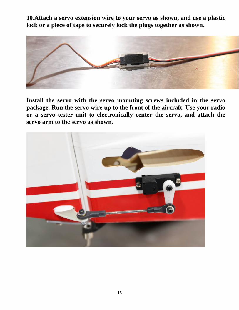
10.Attach a servo extension wire to your servo as shown, and use a plastic lock or a piece of tape to securely lock the plugs together as shown.
Install the servo with the servo mounting screws included in the servo package. Run the servo wire up to the front of the aircraft. Use your radio or a servo tester unit to electronically center the servo, and attach the servo arm to the servo as shown.
16
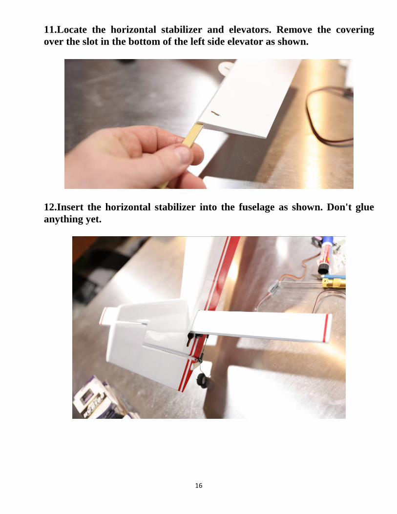
11.Locate the horizontal stabilizer and elevators. Remove the covering over the slot in the bottom of the left side elevator as shown.
12.Insert the horizontal stabilizer into the fuselage as shown. Don't glue anything yet.
17
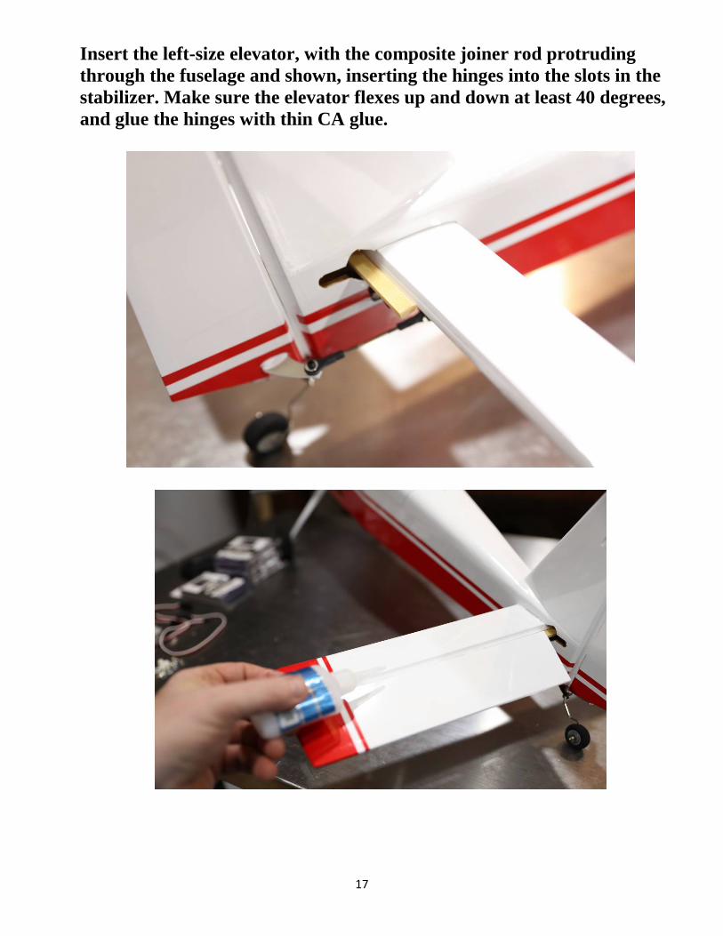
Insert the left-size elevator, with the composite joiner rod protruding through the fuselage and shown, inserting the hinges into the slots in the stabilizer. Make sure the elevator flexes up and down at least 40 degrees, and glue the hinges with thin CA glue.
18
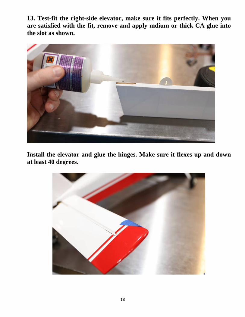
13. Test-fit the right-side elevator, make sure it fits perfectly. When you are satisfied with the fit, remove and apply mdium or thick CA glue into the slot as shown.
Install the elevator and glue the hinges. Make sure it flexes up and down at least 40 degrees.
19
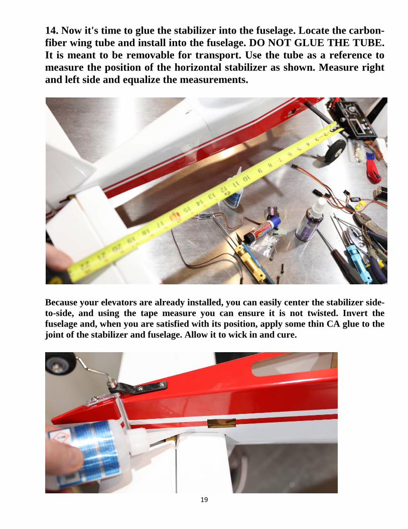
14. Now it's time to glue the stabilizer into the fuselage. Locate the carbon-fiber wing tube and install into the fuselage. DO NOT GLUE THE TUBE. It is meant to be removable for transport. Use the tube as a reference to measure the position of the horizontal stabilizer as shown. Measure right and left side and equalize the measurements.
Because your elevators are already installed, you can easily center the stabilizer side-to-side, and using the tape measure you can ensure it is not twisted. Invert the fuselage and, when you are satisfied with its position, apply some thin CA glue to the joint of the stabilizer and fuselage. Allow it to wick in and cure.
20
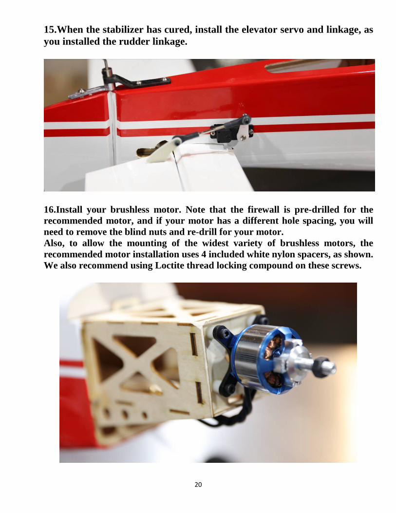
15.When the stabilizer has cured, install the elevator servo and linkage, as you installed the rudder linkage.
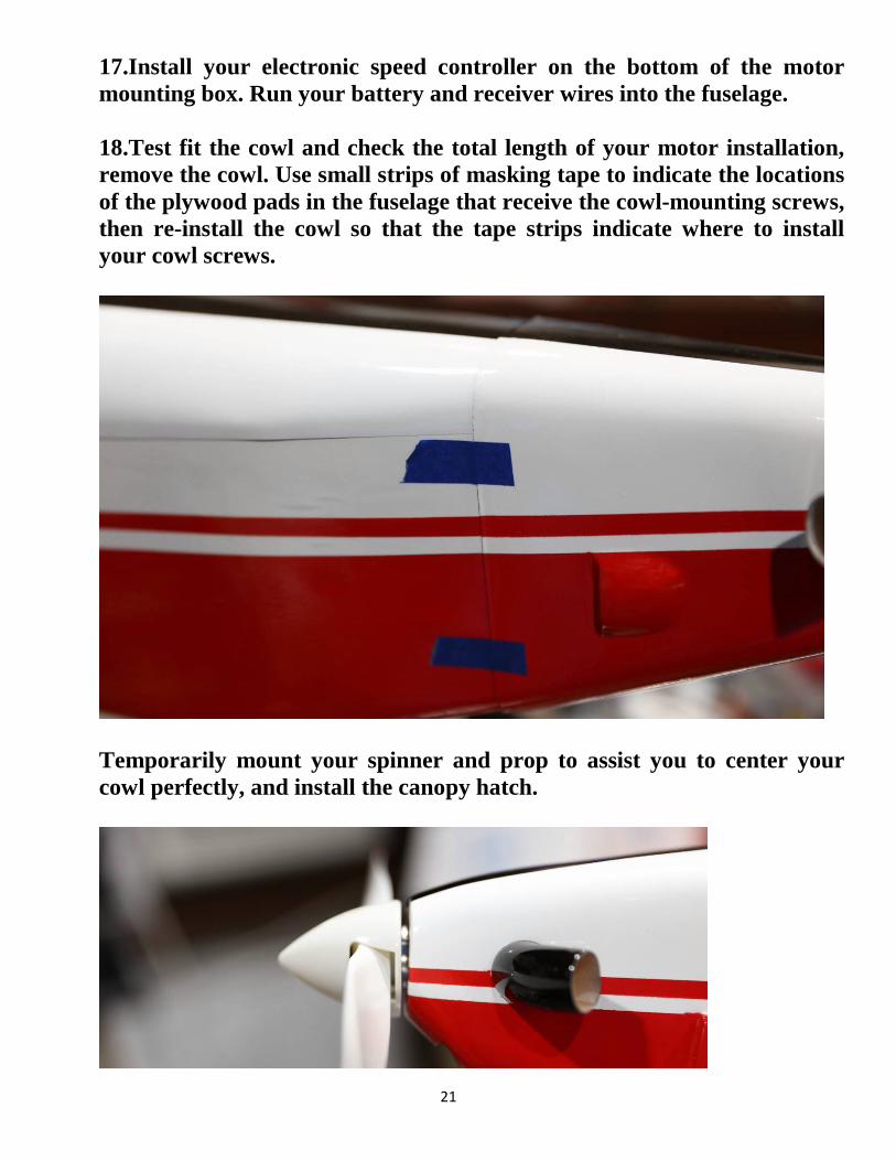
16.Install your brushless motor. Note that the firewall is pre-drilled for the recommended motor, and if your motor has a different hole spacing, you will need to remove the blind nuts and re-drill for your motor. Also, to allow the mounting of the widest variety of brushless motors, the recommended motor installation uses 4 included white nylon spacers, as shown. We also recommend using Loctite thread locking compound on these screws.
21
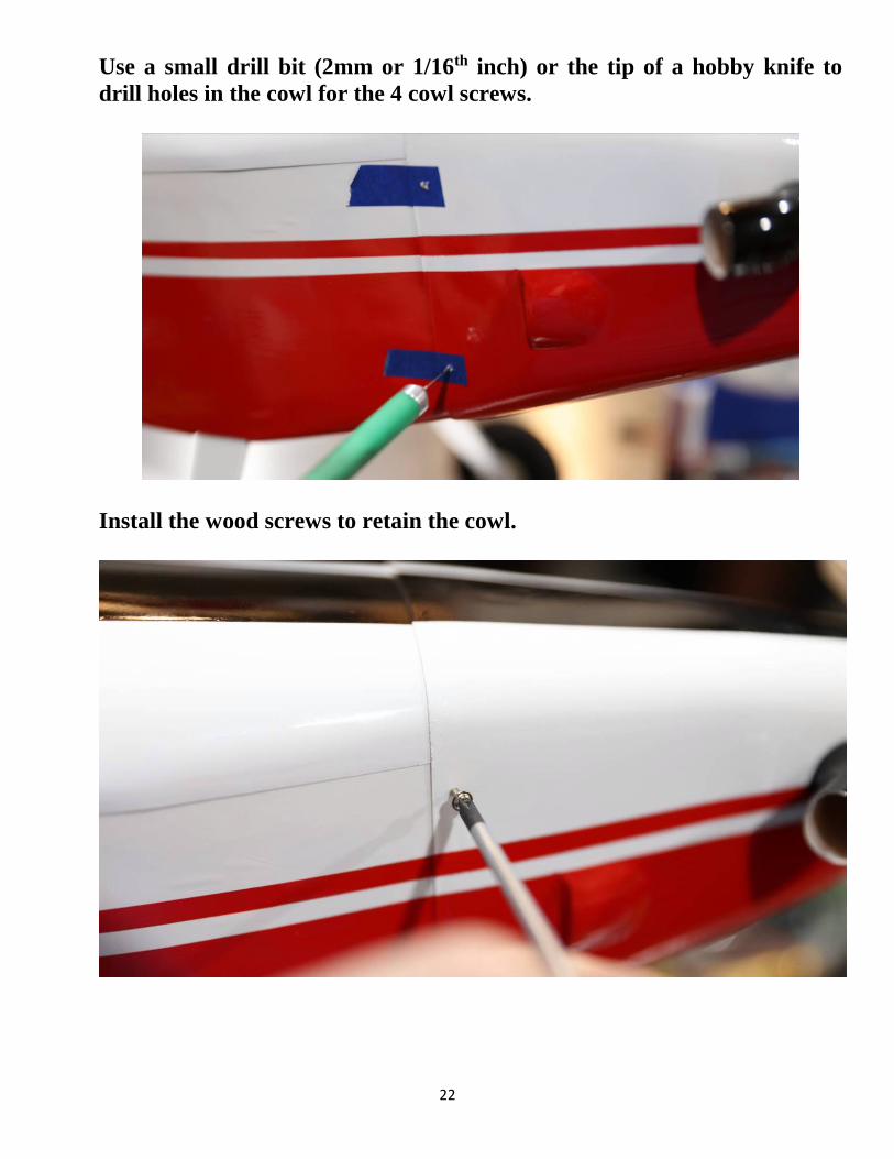
17.Install your electronic speed controller on the bottom of the motor mounting box. Run your battery and receiver wires into the fuselage. 18.Test fit the cowl and check the total length of your motor installation, remove the cowl. Use small strips of masking tape to indicate the locations of the plywood pads in the fuselage that receive the cowl-mounting screws, then re-install the cowl so that the tape strips indicate where to install your cowl screws.
Temporarily mount your spinner and prop to assist you to center your cowl perfectly, and install the canopy hatch.
22
Use a small drill bit (2mm or 1/16th inch) or the tip of a hobby knife to drill holes in the cowl for the 4 cowl screws.
Install the wood screws to retain the cowl.
23
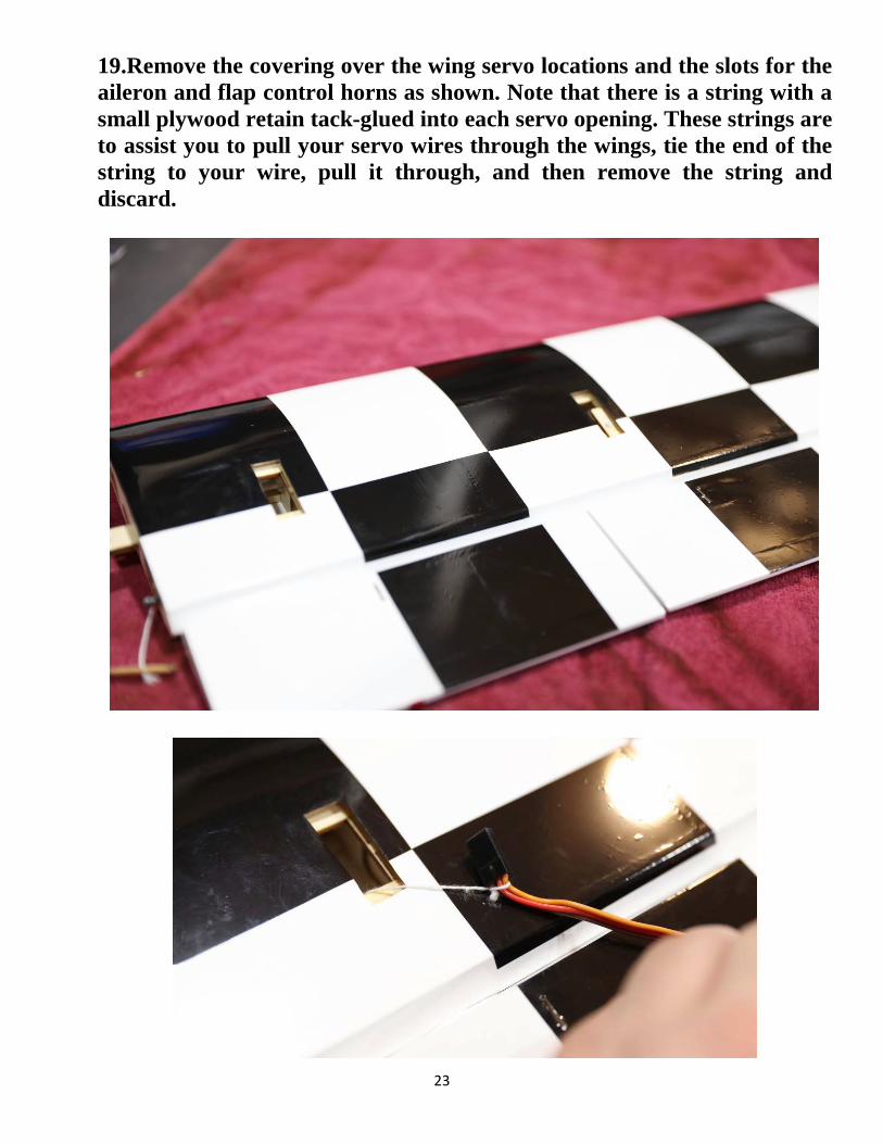
19.Remove the covering over the wing servo locations and the slots for the aileron and flap control horns as shown. Note that there is a string with a small plywood retain tack-glued into each servo opening. These strings are to assist you to pull your servo wires through the wings, tie the end of the string to your wire, pull it through, and then remove the string and discard.
24
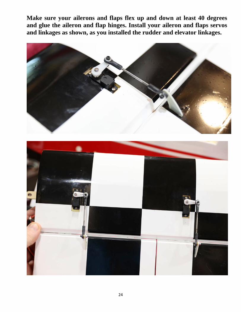
Make sure your ailerons and flaps flex up and down at least 40 degrees and glue the aileron and flap hinges. Install your aileron and flaps servos and linkages as shown, as you installed the rudder and elevator linkages.
25
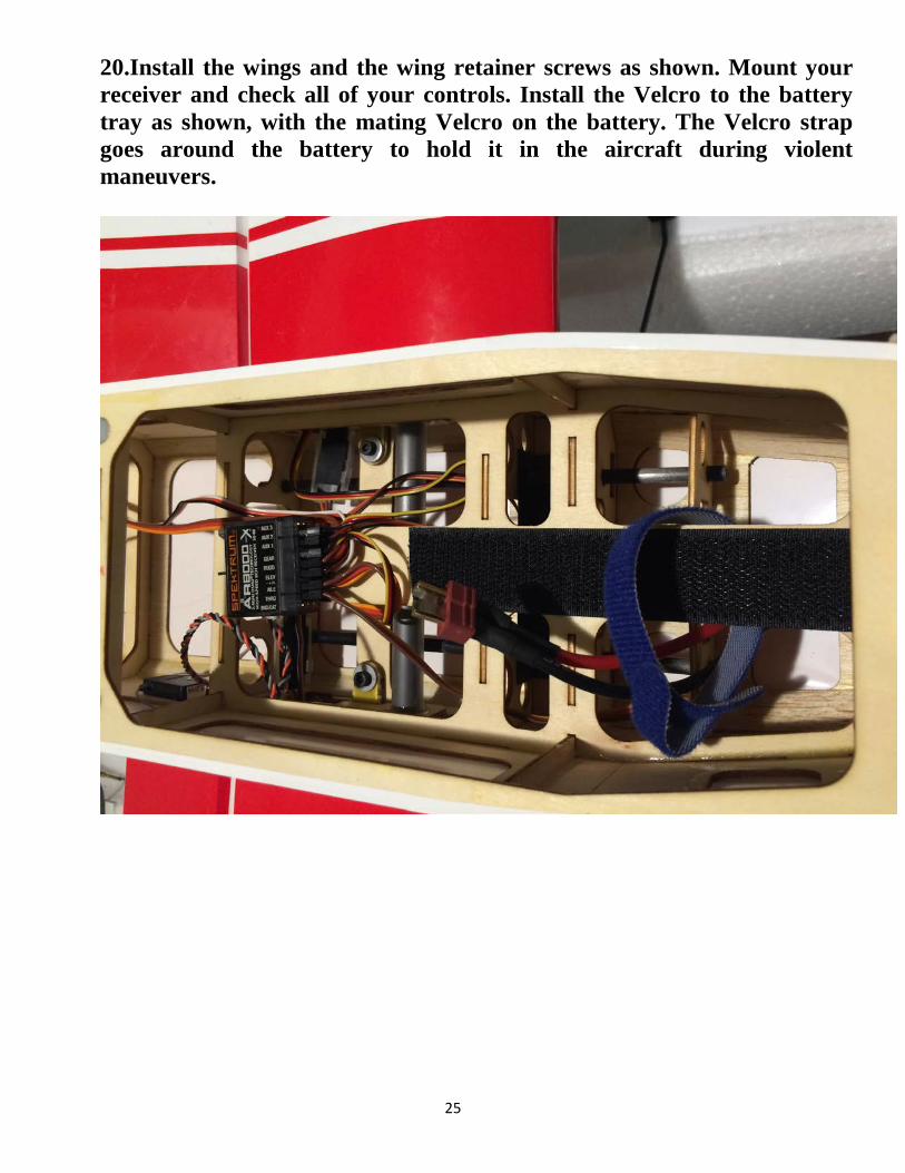
20.Install the wings and the wing retainer screws as shown. Mount your receiver and check all of your controls. Install the Velcro to the battery tray as shown, with the mating Velcro on the battery. The Velcro strap goes around the battery to hold it in the aircraft during violent maneuvers.
26
Set-up and Trimming The CG range for the 44" Turbo Duster is between 2 inches (50mm) and 2.5 inches (62mm) behind the leading edge of the wing. Make a mark on the bottom of the wing to indicate this balance location and support the aircraft with your fingertips, or on a balance stand, at this location. Move your flight battery forward or back as necessary so that the plane rests level in this range. There is plenty of room on the battery tray to move your battery to achieve this CG location. Depending on your flying style you can adjust the position of the battery to alter the CG to accommodate your preferences. We recommend using the 2 inch (50mm) balance point for your maiden flight. Once you are familiar with the aircraft, you can move the battery back to make the controls more responsive. I also highly recommend taking the time to properly set up your rates and exponential settings. Setting up low rates for precision maneuvers and high rates for aggressive aerobatic flight will allow you to experience the best attributes of the Turbo Duster or any aircraft for that matter. Here are some suggested rates to get started with. These are the rates and exponential values I feel comfortable with. They may feel awkward to you and if so please adjust to your taste. Elevator: Low rate-8-10 degrees; 15-20% Exponential Aerobatic rate-30-40 degrees; 40-50% Exponential Rudder: Low rate-20 degrees; 45-50% Exponential Aerobatic rate- 40 degrees; 60-70% Exponential Aileron: Low rate-15-20degrees; 40-45% Exponential Aerobatic rate- 30-35 degrees; 50-60% Exponential Flaps: The flaps are designed to be mixed with ailerons for a variety of aerobatic capabilities. For simple flap use to slow the aircraft for landing, use 35-45 degrees of down flap. For best rolling performance, mix your flaps to perfectly match the motion of your ailerons, creating one large aileron surface. The Duster responds very well to other flap mixes, such as crow mixing, and mixing flaps to elevators (down flap with up elevator, and up flap with down elevator) to increase pitch performance. Experiment, and see what you like! NOTE: For slow flight, when the flaps are down 35-45 degrees, the ailerons should remain neutral. Also dropping the ailerons will make the airplane unstable.
27
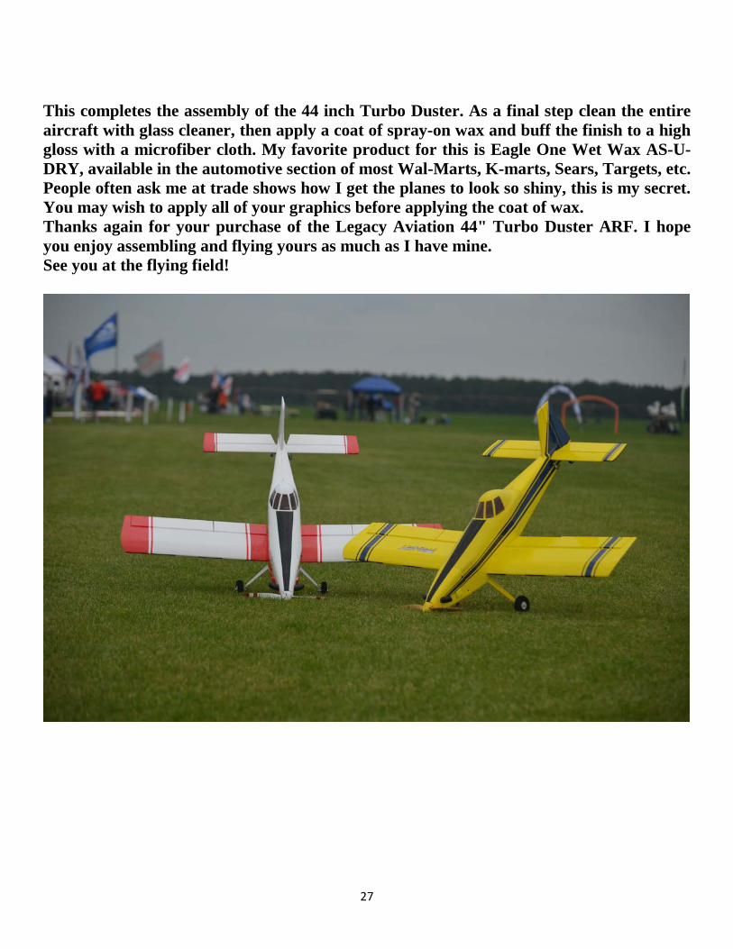
This completes the assembly of the 44 inch Turbo Duster. As a final step clean the entire aircraft with glass cleaner, then apply a coat of spray-on wax and buff the finish to a high gloss with a microfiber cloth. My favorite product for this is Eagle One Wet Wax AS-U-DRY, available in the automotive section of most Wal-Marts, K-marts, Sears, Targets, etc. People often ask me at trade shows how I get the planes to look so shiny, this is my secret. You may wish to apply all of your graphics before applying the coat of wax. Thanks again for your purchase of the Legacy Aviation 44" Turbo Duster ARF. I hope you enjoy assembling and flying yours as much as I have mine. See you at the flying field!