Embed Size (px)
Citation preview

Christoph ReinhartL09 Daylight Simulations
4.401/4.464 Environmental Technologies in Buildings
Massachusetts Institute of TechnologyDepartment of ArchitectureBuilding Technology Program
1

Lighting Module Light and Human Vision Daylighting Design Principles Daylight Simulations & Metrics Visual Comfort Electric Lighting
√√
2
Daylight Simulations
3
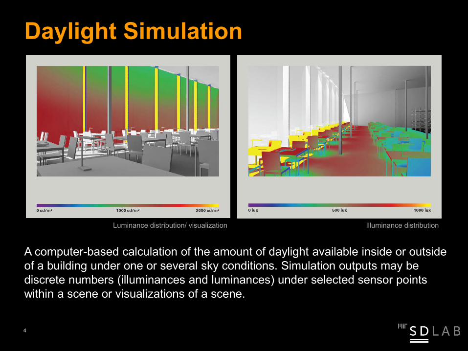
A computer-based calculation of the amount of daylight available inside or outside of a building under one or several sky conditions. Simulation outputs may be discrete numbers (illuminances and luminances) under selected sensor points within a scene or visualizations of a scene.
Daylight Simulation
Luminance distribution/ visualization Illuminance distribution
4
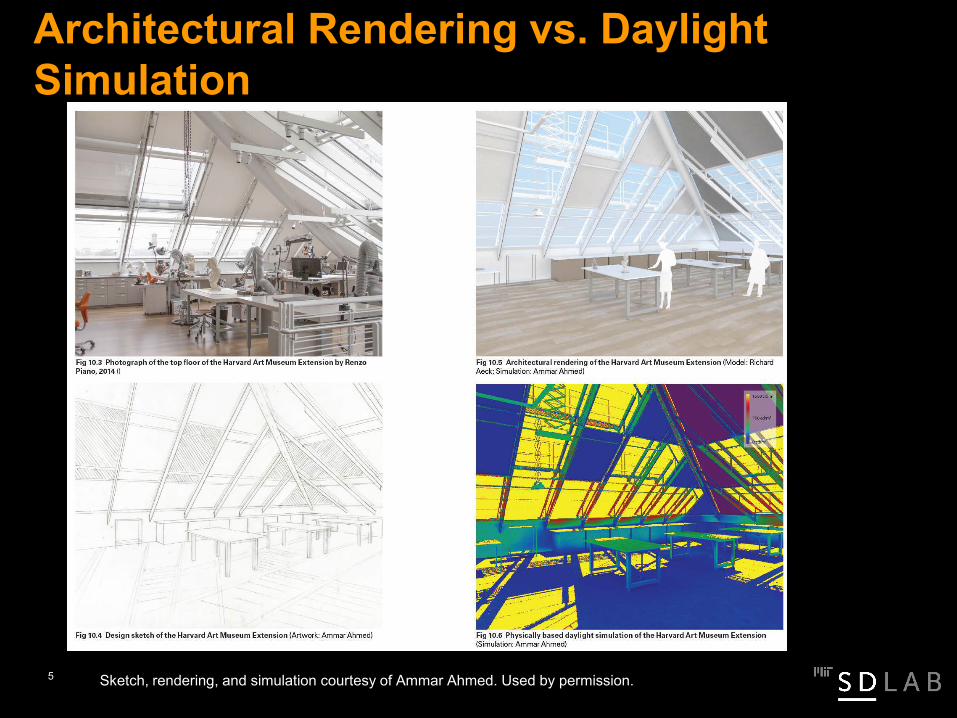
Architectural Rendering vs. Daylight Simulation
Sketch, rendering, and simulation courtesy of Ammar Ahmed. Used by permission.5

Architectural vs. Daylight Models Generally both model types are very similar.
To use an architectural model for daylighting analysis, different material typeshave to be organized by layers.
You have to take care that material properties are assigned correctly and thatall ‘relevant’ objects in your scene, such as trees, neighboring buildings, and wallthicknesses are included. Also pay attention to light leaks.
6

Why Daylighting Simulations? To demonstrate code compliance and to reduce risk. (Think of LEEDgreen building certification.)
To compare different design variants.
7

How often does that actually happen?
Paper H W Samuelson, A Lantz and C F Reinhart, "Non-technical barriers to energy model sharing and reuse." Building and Environment, 54, pp. 71-76 (2012).
Increase impact, improve communication
8

Is there interest in change?
9

Daylighting – Attitude towards Simulations
Positive attitude throughout. (Unclear why some experts fall into category 1.) Broad consensus regarding interest into training designers in the use of simulations.
Designers
I have not seen a case in which this type of analysis has helped us to design a better building.
I appreciate insight gained from daylight simulations provided during design reviews by our sustainability consultants.
I highly value insight gained from daylight simulations and believe that some of the simulations should be conducted by designers, if adequate training is provided.
I highly value insight gained from daylight simulations and already use them during design.
Experts
10

Elements needed for a DL Simulation
Building Model
Area of Interest (analysis grid)
Sky Model
Simulation Algorithm
11

1920s Waldram Diagrams
1940s Daylight Factor Protractors + Original Split Flux Method
1980s Radiosity
1980s Raytracing
1990s Split Flux Method in Ecotect
Daylight Factor Calculation Methods
12
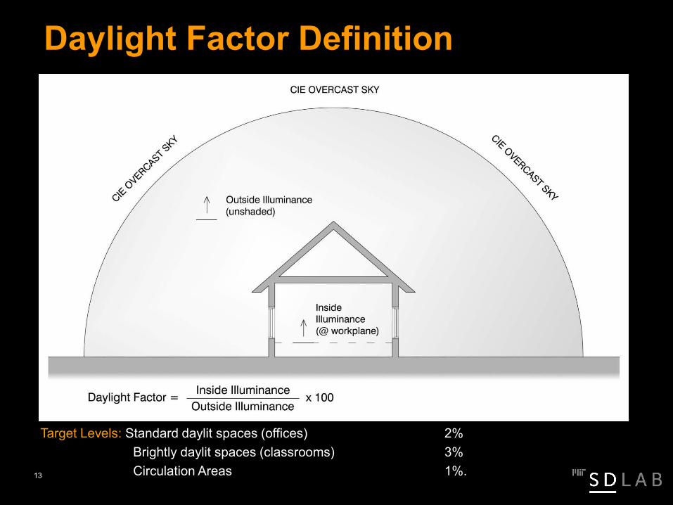
Daylight Factor Definition
Target Levels: Standard daylit spaces (offices) 2%Brightly daylit spaces (classrooms) 3%Circulation Areas 1%.13
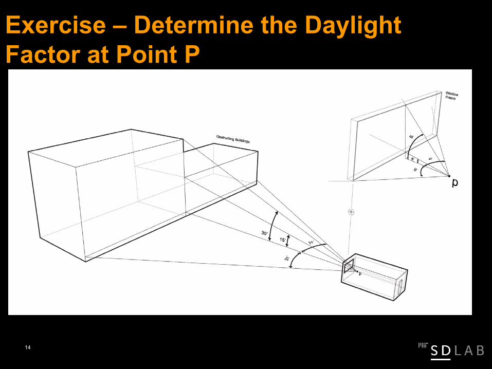
Exercise – Determine the Daylight Factor at Point P
14
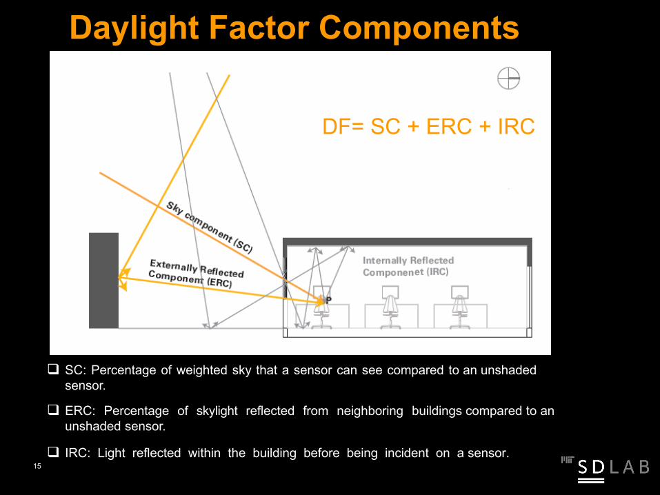
Daylight Factor Components
SC: Percentage of weighted sky that a sensor can see compared to an unshaded sensor.
ERC: Percentage of skylight reflected from neighboring buildings compared to an unshaded sensor.
IRC: Light reflected within the building before being incident on a sensor.
DF= SC + ERC + IRC
15

Frame Factor
Waldram Diagram
tvis86 white squares16

Frame Factor
Waldram Diagram
tvis16 dark gray squaresReflected Light
17

Internally Reflected Component
τ = visual light transmittance
W = window area [m]
A = area of all internal surfaces
R = area weighted mean reflectance
18
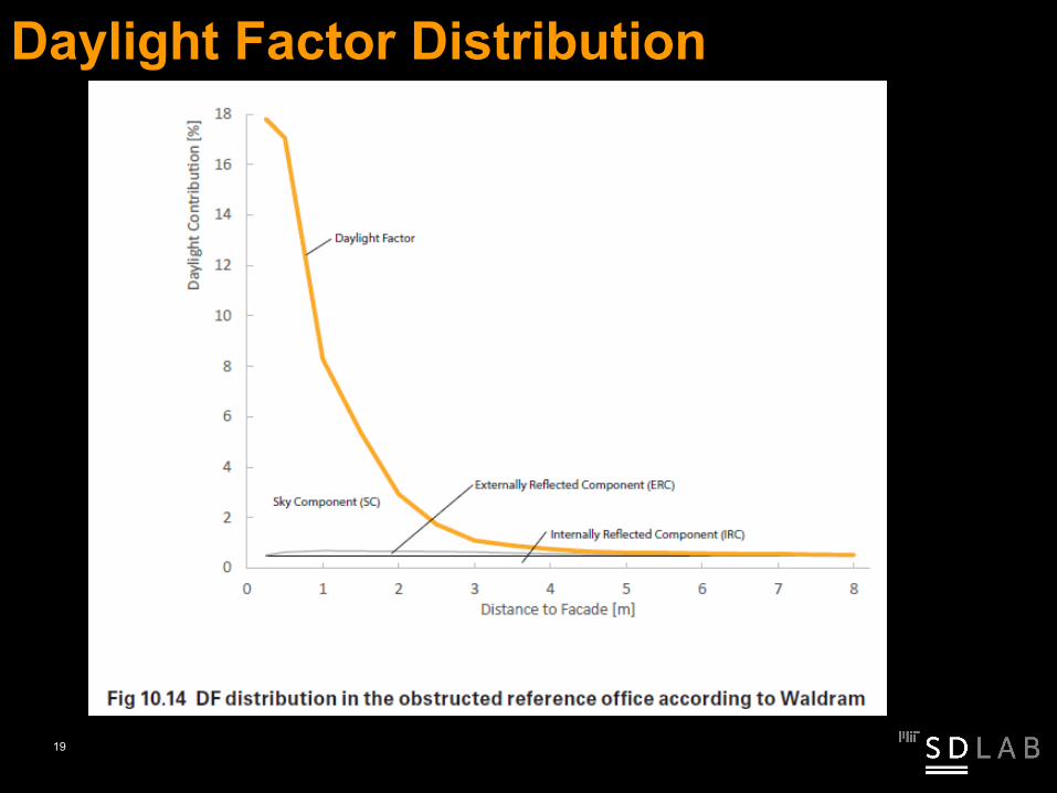
Daylight Factor Distribution
19

© Square One Research. All rights reserved. This content is excluded from our Creative Commons license. For more information, see https://ocw.mit.edu/help/faq-fair-use/.
Design Sky values represent a horizontal illuminance level that is exceeded 85% of the time between the hours of 9 am and 5 pm throughout the working year. Thus they also represent a worst-case scenario that you can design to and be sure your building will meet the desired light levels at least 85% of the time.
Design Sky Values
20

BRE Protractors
21

BRE Protractors
22

BRE Protractors
C-DB-D A’-E = B’-E
Frame Factortvis
Reflected Light tvis (reference)
23

BRE Protractors
24

A geometric version of the Split Flux Method (BRE)
Raytracing: each ray represents an approximately equal solid angle of sky
Split Flux Method in Ecotect
© Square One Research. All rights reserved. This content is excluded from our Creative Commons license. For more information, see https://ocw.mit.edu/help/faq-fair-use/.
25

Comparison of Methods
For a simple scene, all methods are comparable in thetarget range.
26

Comparison of a Best Practice Model using Ecotect-Split-Flux vs. Radiance
Dramatic difference between both engines due to wall thicknessPaper: Ibarra D, Reinhart C F, "Daylight factor simulations - 'How close do simulation beginners 'really' get?“ Proceedings Building Simulation 2009, www.ibpsa.org/proceedings/BS2009/BS09_0196_203.pdf27
Radiosity
28

Originally developed in 1950s to describe radiation heat exchange between surfaces
Adopted during 1980 at Cornell for computer rendering
Goal to move beyond the constant “ambient”/ background illumination term
Assumption that all surfaces are Lambertian
Radiosity
29

Diffuse versus Specular Reflectance
The reflectance of most surfaces can be approximated into adiffuse and specular reflectance term.30
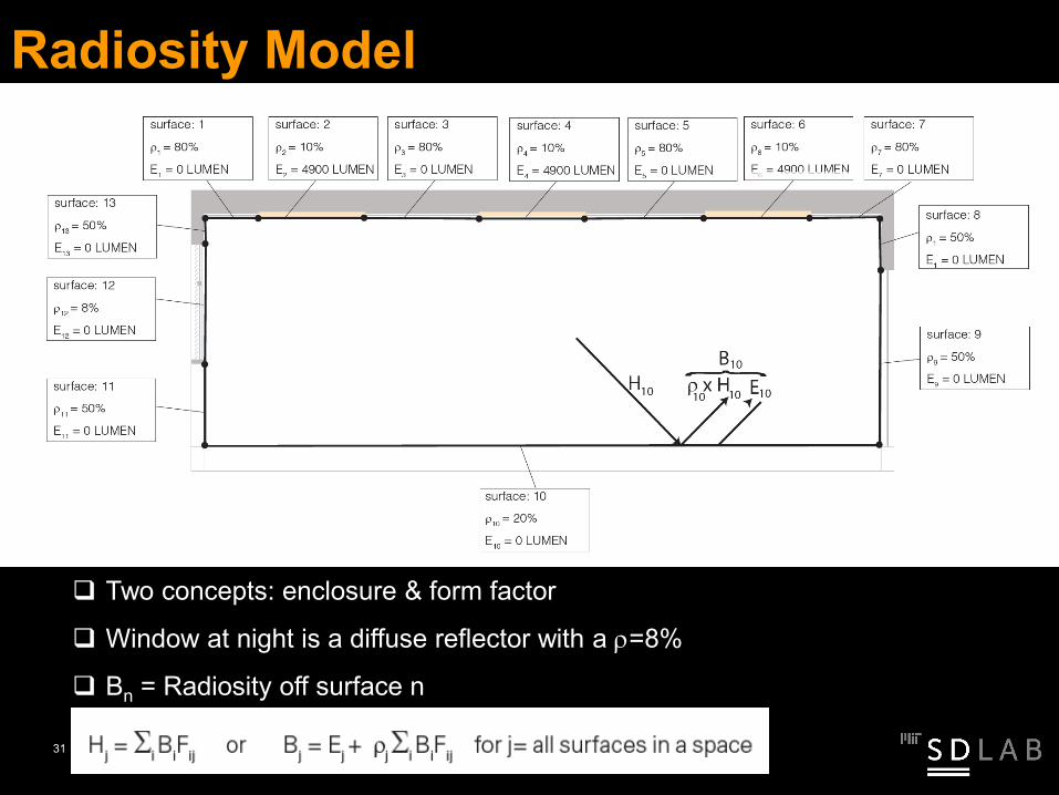
Radiosity Model
Two concepts: enclosure & form factor
Window at night is a diffuse reflector with a ρ=8%
Bn = Radiosity off surface n
31
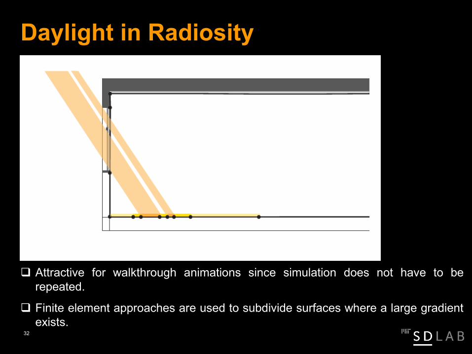
Daylight in Radiosity
Attractive for walkthrough animations since simulation does not have to berepeated.
Finite element approaches are used to subdivide surfaces where a large gradientexists.
32

Radiance
33

Survey on the Use of Daylight Simulations
185 participants from 27 countries (40% Canada & US)
validation seems less of an issue
out of 40 tools mentioned, >50% of votes for RADIANCE based tools
Paper: CF Reinhart and A Fitz, "Findings from a survey on the current use of daylight simulations during building design." Energy and Buildings 38:7 pp. 824-835 (2006).
© NRCC. All rights reserved. This content is excluded from our Creative Commons license. For more information, see https://ocw.mit.edu/help/faq-fair-use/.
34

What is Radiance? Validated backwards raytracer (similar to mental ray).
35

What is Radiance? Validated backwards raytracer (similar to mental ray). Supports a wide variety of material properties and sky models. Has a longish learning curve. (“Magic” lies in simulation parameters.)
Note: If you really want to understand Radiance you will have to read the relevant sections from the Rendering with Radiance book!
36
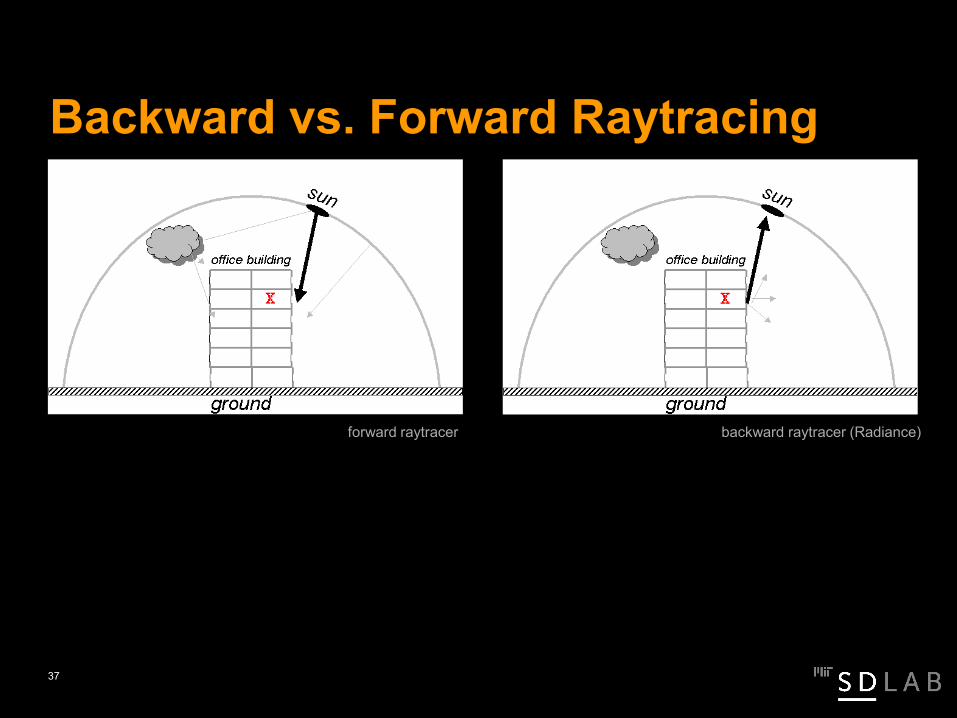
forward raytracer backward raytracer (Radiance)
Backward vs. Forward Raytracing
37
Accuracy of Daylight Simulations
The Radiance/Daysim daylight simulation program can efficiently and reliably model annual illuminance timeseries with a mean relative error of 20%.
Papers: Mardaljevic, J, 1995, “Validation of a Lighting Simulation Program under Real Sky Conditions,” Lighting Research &Technology 27:4, pp. 181–188; Reinhart C F, Andersen M, 2006, “Development and validation of a Radiance model for a translucentpanel,” Energy and Buildings 38:7 pp. 890-904; Reinhart C F, Walkenhorst O, 2001, “Dynamic RADIANCE-based daylight simulationsfor a full-scale test office with outer venetian blinds,” Energy & Buildings, 33:7 pp. 683-697; Reinhart C F, Herkel S, 2000 “Thesimulation of annual daylight illuminance distributions- A state of the art comparison of six RADIANCE based methods,” Energy &Buildings, 32:2 pp. 167-187.
38

Radiance Material Modifers
Supports a wide variety of material properties and sky models.39

Simulation Parameters
“Magic” lies in simulation parameters. Recommended simulation parameters for a simple scene.
ambient bounces
ambient division
ambient sampling
ambient accuracy
ambient resolution
direct threshold
direct sampling
5 1000 20 0.1 300 0 0
40

ambient bounces
ambient division
ambient sampling
ambient accuracy
ambient resolution
direct threshold
direct sampling
5 1000 20 0.1 300 0 0
Radiance Simulation Parameters I
simulation resolution =max scene dimensions x ambient accuracy
ambient resolution
Example:100 m x 0.1
300 ~ 3 cm (window mullion)
41

USDA Consolidation LaboratoriesAmes, Iowa - AEC
Balance of daylight distribution in adjacent office and laboratory spaces.Rules of thumb do not apply any more.
Courtesy of Zack Rogers, PE, President, Daylighting Innovations. LLC. Used with permission.
42

higher raytraing parameters for blinds raytracing detail
Radiance Scene Complexity II
ambient bounces
ambient division
ambient sampling
ambient accuracy
ambient resolution
direct threshold
direct sampling
7 1500 100 0.1 300 0 0
recommended Radiance simulation parameters
43
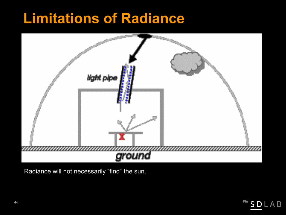
Radiance will not necessarily “find“ the sun.
Limitations of Radiance
44

Photonmapping
Papers: R. Schregle, 2003, “Bias Compensation for Photon Maps,” Computer Graphics Forum, 22:4, pp. 729–742; R. Schregle, L.O. Grobe, and S. Wittkopf, 2016, “An Out-of-Core Photon Mapping Approach to Daylight Coefficients,” Journal of Building Performance Simulation 9:6 pp 620–632.
Image courtesy of Lars O. Grobe. Used by permission.45

Common Simulation Mistakes
46
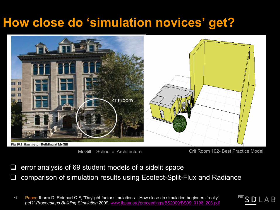
How close do ‘simulation novices’ get?
McGill – School of Architecture Crit Room 102- Best Practice Model
error analysis of 69 student models of a sidelit space comparison of simulation results using Ecotect-Split-Flux and Radiance
Paper: Ibarra D, Reinhart C F, "Daylight factor simulations - 'How close do simulation beginners 'really' get?“ Proceedings Building Simulation 2009, www.ibpsa.org/proceedings/BS2009/BS09_0196_203.pdf
47

Error Sources: Geometric Modeling
Highest result
Mean DF = 10%• Window head height
too high
• No wall thickness
48

Mean DF = 7.5%
• No wall thickness
• No real trees (justconstruction lines)
Error Sources: Software Interoperability
49

Error Sources: Material Properties
Mean DF = 1.5%• No wall thickness
• No glazings
50

69 Student Models
Ecotect results lie over and under Radiance results A closer analysis shows that none of the students built a ‘correct’ model Better results in 2006 probably due to ‘simulation tips’
51

SimulationChecklist
52

Spring 2012 MIT 4.430 Daylighting
53

Spring 2012 MIT 4.430 Daylighting
Simulation of 10.485. Practicing good simulation habits. Building trust in one’s own modeling skills.
54

Spring 2012 MIT 4.430 Daylighting
Teaching daylight simulation in multiple steps leads to significantlybetter novices models.
Paper: Ibarra D, Reinhart C F, "TEACHING DAYLIGHT SIMULATIONS – IMPROVING MODELING WORKFLOWS FOR SIMULATION NOVICES,”Proceedings Building Simulation 2013
55

Papers: Jones N L, C F Reinhart, 2017, “Experimental validation of ray tracing as a means of image-based visual discomfort prediction,” Building andEnvironment, 113, pp. 131–150; N L Jones and C F Reinhart, “Irradiance Caching for Global Illumination Calculation On Graphics Hardware,” Proceedings of2014 ASHRAE/IBPSA-USA Building Simulation Conference, Atlanta, GA, September 10-12, 2014; N L Jones and C F Reinhart , “Physically Based Global
56
Illumination Calculation Using Graphics Hardware,” Proceedings of esim 2014, IBPSA Canada, Ottawa, ON, May 7-10, 2014.
Irradiance caching on the GPU produces a twenty-fold speedup. Smoother gradients are produced by creating the irradiance cache prior to the final gather.
https://web-cert.mit.edu/SustainableDesignLab/projects/Accelerad/index.html
AcceleRAD – CPU, Cloud or GPU?
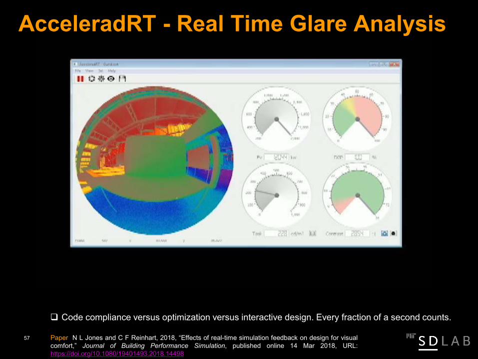
AcceleradRT - Real Time Glare Analysis
Code compliance versus optimization versus interactive design. Every fraction of a second counts.
Paper N L Jones and C F Reinhart, 2018, “Effects of real-time simulation feedback on design for visualcomfort,” Journal of Building Performance Simulation, published online 14 Mar 2018, URL:https://doi.org/10.1080/19401493.2018.14498
57

Real Time Design Analysis
Highly optimized daylight availability/glare analysis in DIVA4Same analysis in real time in AccereradRT40 test subjects went through two shading design studies for 20 minutes each.
Paper N L Jones and C F Reinhart, 2018, “Effects of real-time simulation feedback on design for visualcomfort,” Journal of Building Performance Simulation, published online 14 Mar 2018, URL:
https://doi org/10 1080/19401493 2018 14498
AccereradRTDIVA4
58

Real Time Design Analysis
Real time users were in a state of flow with barely any state over 20 seconds. AcceleradRT results somewhat closer to the Pareto front.
Paper N L Jones and C F Reinhart, 2018, “Effects of real-time simulation feedback on design for visualcomfort,” Journal of Building Performance Simulation, published online 14 Mar 2018, URL:https://doi.org/10.1080/19401493.2018.14498
59

Real Time Design Analysis
Intense/ exhilarating experience
Paper N L Jones and C F Reinhart, 2018, “Effects of real-time simulation feedback on design for visualcomfort,” Journal of Building Performance Simulation, published online 14 Mar 2018, URL:https://doi org/10 1080/19401493 2018 14498
60

Daylight Availability Metrics
61

Rights of Light
62

Historical Background: “Right of Light”
“Before WWII, legal rights of light constituted practically the only profitable field for daylight experts.”
-P.J. Waldram, “A Measuring Diagram for Daylight Illumination” (1945)
63

Spite Fence
Photograph of San Francisco in 1877, taken by Eadweard Muybridge. This image is in the public domain.
Charles Crocker, a railroad baron, built an abnormally large wall around his neighbor’s house who had refused to sell his property to Crocker.64

Daylight Factor Analysis - Example
65

Daylight Factor – Design Implications window head height reference
glazing type narrow floor plan
66

Daylight Factor – Design ImplicationsThe daylight factor optimized building is fully glazed.
Note, there are LEED certified buildings that are fully glazed!
67

Daylight Factor – Design Implications III
Daylight factor does not take glare or solar gain control into account. Theconsequence of too large glazings:Venetian blinds are closed most of the time.
Common argument:• overcast sky as a worst case scenario• venetian blinds (even if closed) still admit sufficient DL
68

Combine Daylight Factor Analysis with Shading Studies
69
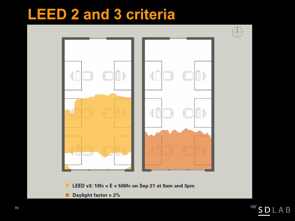
LEED 2 and 3 criteria
70

People can work under very bright sky conditions
Photo courtesy of Ammar Ahmed. Used with permission.71

Limitations of Point-in-Time Daylight Availability Metrics Do not consider local climate data
Ignore programmatic use (occupancy patterns, lighting requirements)
Neglect the impact of movable shading devices (venetian blinds)
72

Climate-based Metrics
73

Solution? – Climate-Based Metrics As opposed to a static simulation that only considers one sky condition
at a time, dynamic daylight simulations generate annual time seriesof interior illuminances and/or luminances.
74

Daylight Coefficients
75

Spatial Daylight Autonomy Calculation
Image courtesy of Solemma. Used with permission.
76
Questions?
www.daylight1-2-3.comwww.daysim.com
77

MIT OpenCourseWare https://ocw.mit.edu/
4.401/4.464 Environmental Technologies in Buildings Fall 2018
For information about citing these materials or our Terms of Use, visit: https://ocw.mit.edu/terms.


![Pre-Engineered Buildings Structural Steel Buildings ...€¦ · Pre-Engineered Buildings Structural Steel Buildings LEADERS IN THE STEEL BUILDINGS INDUSTRY mKÁúeTsk_ vis½y]sSahkmµ](https://img.pdfslide.net/doc/110x75/5f069e707e708231d418e449/pre-engineered-buildings-structural-steel-buildings-pre-engineered-buildings.jpg)