Embed Size (px)
Citation preview

FORM NO. 45446 (05/30/17) the fastest way to purchase parts www.speedepart.com
IMPORTANT: The engine is shipped without oil. Add oil before starting the engine.
IMPORTANT: The wheel bearings are not prelubricated. Fill the wheel hubs with grease after assembling the wheels to the axle.
IMPORTANT: Check engine air filter prior to each use. Follow the maintenance schedule on page 18 of this manual.
IMPORTANT: Hose extension kit #65640 may be required for rear engine tractors and zero turn tractors.
45-0541
MOW-N-VAC

2
TABLE OF CONTENTS
SAFETY ........................................................................... 3ACCESSORIES AND ATTACHMENTS ........................... 5FULL SIZE HARDWARE CHART (CART) ....................... 6FULL SIZE HARDWARE CHART (ADAPTER) ................ 7CARTON CONTENTS ..................................................... 8ASSEMBLY ...................................................................... 9OPERATION .................................................................. 16
MAINTENANCE ............................................................ 18SERVICE AND ADJUSTSMENTS ................................. 19STORAGE AND OPTIONAL USE ................................. 19TROUBLESHOOTING ................................................... 20REPAIR PARTS ........................................................ 21-24PARTS ORDERING/SERVICE ...................... BACK PAGE

3
SAFETY
Any power equipment can cause injury if operated improperly or if the user does not understand how to operate the equipment. Exercise caution at all times when using power equipment.
• Read and follow all instructions in this manual before attempting to assemble or operate this equipment. Failure to comply with these instructions may result in personal injury. Keep this manual in a safe place for future reference and for ordering replacement parts.
• Read this operating and service instruction manual carefully. Be thoroughly familiar with the controls and proper use of this power vacuum.
• Read the vehicle owners manual and vehicle safe operation rules before using this equipment.
• Never allow children under 16 to operate this Mow-N-Vac. Children 16 years and older should only operate under close parental supervision.
• DO NOT allow anyone to operate this equipment without proper instructions.
• DO NOT allow passengers to ride on this equipment or the towing vehicle.
• Keep the area of operation clear of others, particularly small children and pets.
• Check fuel before starting engine. Do not fill fuel tank indoors, while engine is running or while engine is hot. Wipe off any spilled fuel before starting engine.
• Engine and muffler get hot. Do not touch! To avoid fire hazard, keep clean of debris and other accumulations.
• Never store Mow-N-Vac with fuel in tank. Allow engine to cool before storing in any enclosure.
• Do not change engine governor settings.• Do not operate engine if air cleaner or cover is removed
except for adjustment. Removal of these parts could create a fire hazard.
• Keep hands, feet, face, long hair and clothing out of inlet and discharge area. There are ROTATING BLADES inside these openings.
• Before cleaning, repairing or inspecting, make certain all moving parts come to a complete stop. Disconnect spark plug wire and keep wire away from plug to prevent accidental starting. Keep throttle control lever in stop position.
• If the Mow-N-Vac should become blocked with debris at any point, shut engine off and wait until the impeller comes to a complete stop before attempting to remove the obstruction. Disconnect spark plug wire to prevent accidental starting.
• If the cutting mechanism strikes a foreign object, or if your Mow-N-Vac should start to vibrate abnormally, stop the engine immediately, disconnect spark plug wire and move the wire away from the spark plug. Allow the machine to stop and take the following steps. a. Inspect for damage. b. Repair or replace any damaged parts. c. Check for loose parts and tighten to assure continued safe operation.
• Check all bolts for tightness at frequent intervals to help insure safe operation.
• Check top cover frequently for wear. Replace if worn or damaged.
• Never operate Mow-N-Vac unless deck adapter, hose, hose adapter (nozzle), discharge chute (elbow), and top cover are properly attached in their place.
• Do not remove top cover or attempt to empty contents of cart while engine is running.
• Never attempt to change hose adapter (nozzle) or to install remote hose attachment when engine is running.
• Keep all shields and guards (e.g. discharge chute (elbow) and hose adapter (nozzle) in place and securely attached.
• Always wear safety glasses or other suitable eye protection when operating or maintaining this equipment.
• Do not stand behind cart in exhaust discharge area while engine is running.
• Do not operate this equipment while intoxicated or while taking drugs or medication that impairs the senses or reactions.
• When using this equipment, start the vehicle transmission in first (low) gear and then gradually increase speed only as conditions permit.
• Operate this equipment at reduced speed on rough terrain, along creeks and ditches and on slopes to prevent tipping or loss of control. Do not drive too close to a creek or ditch.
• Vehicle braking and stability are affected by the addition of this equipment. Do not fill the Mow-N-Vac to its full capacity without checking the capability of the towing vehicle to safely pull and stop with Mow-N-Vac attached.
• Before operating on any grade (hill) refer to the safety rules in the vehicle owner's manual concerning safe operation on slopes. Also refer to the SLOPE GUIDE on page 25 of this owner's manual. Do not operate on slopes in excess of 10 degrees. STAY OFF STEEP SLOPES!
• Follow the maintenance instructions outlined in this manual.
Look for this symbol to point out important safety precautions. It means — Attention!! Become alert!! Your safety is involved.
DANGER: This Mow-N-Vac was built to be operated according to the rules for safe operation in this manual. As with any type of power equipment, carelessness or error on the part of the operator can result in serious injury. This unit is capable of amputating fingers and hands and throwing objects. Failure to observe the safety instructions could result in serious injury or death.

4
WARNINGTO AVOID SERIOUS INJURY
• Read Owner’s Manual and all safety labels on machine before starting and using machine.• Do Not remove top cover or attempt to empty contents of cart while engine is running.• Do Not stand behind cart in exhaust discharge area while engine is running.• Keep hands, feet, face, long hair and clothing out of chipper inlet, vac inlet, and discharge
area. There are ROTATING BLADES inside these openings.• Wear approved safety glasses and gloves. Avoid loose fitting clothes.• Keep the area of operation clear of all persons, particularly small children and pets.• Keep all shields and guards (e.g. upper chipper chute extension, discharge chute, nozzle
assembly) in place and securely attached.• Check discharge boot frequently for wear. Replace if worn or damaged.• If unit becomes clogged or jammed, shut off engine right away. Do Not attempt to clear
clog or jam with engine running. • Muffler and engine get hot and can cause burns. Do Not Touch. To avoid a fire hazard,
keep leaves, grass and other combustible debris off hot muffler and engine.• Do Not attempt to remove or attach vac nozzle or optional Hose Kit with engine running.• Do Not operate unit unless nozzle or optional Hose Kit is secured in place.• Do Not fill gas tank while engine is running. Allow engine to cool at least 2 minutes before
refueling.
HAZARDOUS ROTATING BLADES INSIDE. KEEP HANDS AWAY FROM ALL OPENINGS. DO NOT REMOVE OR ATTACH HOSE, HOSE ADAPTER, ELBOW OR OPTIONAL HOSE KIT WHEN ENGINE IS RUNNING!
DANGER
This unit is equipped with an internal combustion engine and should not be used on or near unimproved forest-covered, or grass-covered land unless the engine’s exhaust system is equipped with a spark arrester meeting applicable local or state laws (if any). If a spark arrester is used, it should be maintained in effective working order by the operator.
In the State of California the above is required by law (Section 4442 of the California Public Resources Code). Other states may have similar laws. Federal laws apply on federal lands. A spark arrester muffler is available at your nearest engine authorized service center.
WARNING
M117554

5
ACCESSORIES AND ATTACHMENTS
The Remote Hose Kit, Model 45-0253, provides 12' x 5" diameter hose to clean around shrubs, patios, window wells and other areas not accessible to the tractor.

6
FULL SIZE HARDWARE CHART (CART)
REF. NO.
PART NO. QTY. DESCRIPTION
A M84309 8 Nut, Retainer
B 43574 5 Hex Bolt, 3/8-16 x 3"
C 1509-90 4 Hex Bolt, 1/4-20 x 1-1/4"
D 43001 4 Hex Bolt, 3/8-16 x 1"
E 43012 10 Hex Bolt, 1/4-20 x 3/4"
F 47630 4 Hex Bolt, 5/16-18 x 3/4"
Thread Forming
G 43182 8 Hex Bolt, 5/16-18
H 43343 1 Hair Cotter Pin
I 43013 6 Lock Nut, 1/4-20
REF. NO.
PART NO. QTY. DESCRIPTION
J 47598 11 Nut, Hex Flange 1/4-20
K 47189 4 Nylock Nut, 1/4-20
L 47810 8 Nylock Nut, 5/16-18
M HA21362 9 Nylock Nut, 3/8-16
N 1543-69 4 Nylon Washer
O 43088 2 Washer, 1/4" Std.
P R19212016 4 Washer, 5/8"
Q 43010 2 Cotter Pin
R 23353 1 Hitch Pin
S 25910 2 Axle Clip
NOT SHOWN FULL SIZE
C D F
P
M
K
L
I
Q
A B GE
N
O
J
R S
H

7
FULL SIZE HARDWARE CHART (ADAPTER)
NOT SHOWN FULL SIZE
D
E F H
G
A B
I
J
KM N
L
C
O
REF. NO.
PART NO. QTY. DESCRIPTION
A 1509-90 3 Hex Bolt, 1/4-20 x 1-1/4"
B 43840 2 Hex Bolt, 5/16-18 x 1-1/4"
C 43661 4 Hex Bolt, 1/4-20 x 1"
D 43080 2 Carriage Bolt, 5/16" x 3/4"
E 43088 9 Washer, 1/4" Std.
F 47810 3 Nylock Nut, 5/16-18
G 47189 5 Nylock Nut, 1/4-20
H 43081 12 Washer, 5/16" Std.
REF. NO.
PART NO. QTY. DESCRIPTION
I 1543-69 5 Nylon Washer
J 44850 2 Tarp Strap
K 23826 1 Angle Bracket
L 44849 2 "S" Hook
M 23825 1 Mounting Strap
N 23827 1 Mounting Bracket
O 42749 1 S" Hook (Large)

8
CARTON CONTENTS
1 2
7
5
12
17
13
19
22 23
16
15
10
21
6
3
9 11
8
20
REF. NO.
PART NO. QTY. DESCRIPTION
1 48791 1 Cart Tray
2 40343 1 Cart Cover
3 – 1 Engine
4 65518 1 Rope, 36"
5 25742 1 Front Tongue
6 69030 1 Rear Tongue
7 46420 1 Elbow w/ Deflector
8 43793 2 Hose Clamp
9 40880 2 Wheel
10 24527 1 Wheel Support
11 41882 1 Hose
12 25876 2 Brace
REF. NO.
PART NO. QTY. DESCRIPTION
13 24497 1 Latch Stand Bracket
14 49873 2 Lower Support Rod
15 43790 1 Tarp Strap, 25"
16 49974 1 Hose Hanger Rod
17 24386 1 Latch Stand Plate
18 23560 1 Adapter Bracket (Deck)
19 43830 1 Deck Adapter
20 25875 2 Cart Bed Brace
21 26008 1 Axle
22 23560 1 Deck Adapter Bracket
23 25010 1 Attachment Bracket (Deck)

9
ASSEMBLY
• Assemble the rear tongue to the wheel support by sliding the axle through the holes in the tongue and wheel support as shown in figure 2.
HOLE FOR AXLE
FIGURE 1
NOTE: This unit is shipped WITHOUT GASOLINE or OIL. After assembly, see separate engine manual for proper fuel and engine oil recommendations.
TOOLS REQUIRED FOR ASSEMBLY(1) Screwdriver(1) Pliers(2) 7/16" Wrenches(2) 1/2" Wrench(2) 9/16" Wrenches(2) 3/4" Wrenches
REMOVAL OF PARTS FROM CARTONS • Remove the hardware packs and all loose parts from
the cartons.• Lay out and identify parts shown in carton contents.• Lay out and identify parts in the hardware packs.
Keep contents of each hardware package separate.
• Assemble the front tongue on top of the rear tongue using three 3/8" x 3" hex bolts and 3/8" nylock nuts. See figure 1.
• Install the hitch pin and the hair cotter pin in the hitch bracket and front tongue. See figure 1.
3/8" NYLOCK NUT
3/8" x 3"HEX BOLT
HAIRCOTTER PIN
HITCH PIN
FIGURE 2CART ASSEMBLY

10
• Assemble the latch stand plate and latch stand bracket (with alignment tab toward rear of cart) to the cart tray using four 1/4" x 3/4" hex bolts and 1/4" nylock nuts. Tighten nuts after all bolts are in place. See figure 4.
FIGURE 5
1/4" NYLOCK NUT
TAB
1/4" x 3/4"HEX BOLTS
FIGURE 4
• Place the cart bed braces and the cart tray onto the wheel support. Secure latch stand bracket underneath the tongue's latch lock lever. See figure 5.
• Assemble the cart tray and cart bed braces to the wheel support using eight 5/16" x 3/4" hex bolts, retainer nuts, and 5/16" nylock nuts. Tighten nuts after all bolts are in place. See figure 5.
COTTER PIN
WHEEL
5/8" WASHER (IF SPACE ALLOWS)
5/8"WASHER
AXLE
AXLECLIP
FIGURE 3
• Assemble an axle clip, a wheel and a 5/8" washer onto each end of the axle. Assemble a second 5/8" washer onto each end of the axle if space allows. Secure both wheels in place using two cotter pins. See figure 3.
3/8" x 1"HEX BOLT
3/8" x 3"HEX BOLT
3/8" NYLOCK NUTFIGURE 6
• Attach the engine mounting plate to the tongues using two 3/8" x 3" hex bolts in the back holes, two 3/8" x 1" hex bolts in the front holes and four 3/8" nylock nuts. See figure 6.
HINT: For easier assembly, support the rear tongue with a block of wood.
5/16"NYLOCK NUT
CARTBED
BRACE
5/16" x 3/4"HEX BOLT
RETAINERNUT
HINT: Attach retainer nuts between cart bed and cart bed braces to secure 5/16" hex bolts while attaching cart bed braces and wheel support to cart bed.

11
5/16" x 3/4"HEX BOLT(SELF TAP)
NYLON WASHER
HOSE HANGERROD
HOSE CLAMP
HOSE
HOSE ADAPTER(NOZZLE)
FIGURE 7
FIGURE 8
FIGURE 9• Place the hose hanger rod down into the hose hanger
bracket on the impeller housing assembly. See figure 8.
• Place a hose clamp onto the end of the hose. Push the hose onto the hose adapter (nozzle). Tighten the hose clamp onto the hose and hose adapter. Do not collapse the hose adapter when tightening the clamp. See figure 9.
• The remaining hose clamp will be used later to fasten the hose to the deck adapter.
• Attach the plastic elbow to the top of the engine housing using four 5/16" x 3/4" hex bolts (self tapping) and nylon washers. See figure 7.
HINT: Push in on hex bolts as you tighten to form threads.
25" TARPSTRAP
HOSE HANGER ROD
FIGURE 10
• Loop the 25" tarp strap under the hose. Fasten the hooks to the hose hanger rod. See figure 10.

12
1/4" x 3/4" HEX BOLT
1/4" FLANGEDNUT
LOWER SUPPORTROD (BENT)
1/4" LOCKNUT
FIGURE 14
• Assemble a 1/4" x 3/4" bolt and 1/4" lock nut to each end of the second lower support rod. TIGHTEN, then back nut off 1/2 turn. See figure 14.
• Attach the lower support rod to the outside of the top support angle using two 1/4" flanged nuts. TIGHTEN. See figure 14
NOTE: Cart bag not shown for clarity.
1/4" x 3/4" HEX BOLT
1/4" LOCK NUT
FRONT SUPPORT ROD(STRAIGHT)
LOWER SUPPORT ROD(BENT)
FIGURE 13
• Place the front support rod on the outside and the lower support rod on the inside of the top angle support. Attach using two 1/4" x 3/4" hex bolts and 1/4" lock nuts. TIGHTEN nut only until flush with end of bolt. The rods must pivot freely. See figure 13.
NOTE: Cart bag not shown for clarity.
1/4" x 1-1/4" HEX BOLT
1/4" LOCK NUT
FRONT SUPPORT TUBE
TOP SUPPORT ANGLE
FIGURE 12
FIGURE 11
• Secure front support tube to top support angle using two 1/4" x 1-1/4" hex bolts and 1/4" lock nuts. TIGHTEN. Do not over tighten and collapse support tube. See figure 12.
NOTE: Cart bag not shown for clarity.
CART COVER ASSEMBLY
DOUBLE LOOPS
FRONT SUPPORTTUBE CART COVER

13
1/4" x 1-1/4"HEX BOLT
1/4" FLANGEDNUT
BRACE
FIGURE 15
• Attach the braces to the front support tube using two 1/4" x 1-1/4" hex bolts and 1/4" flanged nuts. TIGHTEN. Do not over tighten and collapse support tube. See figure 15.
NOTE: Cart bag not shown for clarity.
• Allow the rope to hang loosely behind the rear of the cart. Use the lanyard to tighten the rope until it firmly secures the cart cover to the cart. See figure 18.
• Ensure lanyard is locked to keep rope in place. See figure 18.
FIGURE 18
1/4" x 3/4"HEX BOLT
1/4" FLANGEDNUT
BRACES
1/4"WASHER
FIGURE 16
• Place the assembled cart cover on top of the cart, aligning the bolts in the top support angle with the holes in the cart. Assemble five 1/4" flanged nuts onto the bolts. DO NOT TIGHTEN YET. See figure 16.
• Attach the bottom of the braces to the top support angle and the cart using two 1/4" x 3/4" hex bolts, 1/4" washers and 1/4" flanged nuts. TIGHTEN. See figure 16
• TIGHTEN the five 1/4" flanged nuts.
BOLT A
BOLT B
• With the rope hanging down loosely, check if the cover fits down freely around the rear of the cart tray. If the cover needs to extend farther to the rear, loosen bolts (a) in figure 17 to slide the support rod rearward.
• If the rear of the cover does not rest down freely around the rear of the cart tray, loosen bolts (b) in figure 17 and tilt the front support tube rearward while sliding the bottom of the braces rearward. Retighten the bolts.
LOCKUNLOCK
LANYARD
FIGURE 17

14
FIGURE 20
• Holding the adapter bracket and the deck adapter together, position the deck adapter on the mower deck. Keeping the edge of deck adapter as close as possible to the offset in the adapter bracket, see if the slot in the adapter bracket can be aligned with one or two of the deflector holes in your mower deck’s discharge opening. If the bracket can not be located correctly using existing holes, it will be necessary to drill one or two 5/16" diameter holes in the deck. See figure 21.
• Position the adapter over the deck opening, and check for fit of cutout as shown in figure 20. Trim cutout, if necessary, to allow tilting of adapter, keeping the fit as close as possible for best vacuum suction.
MOWER DECK
DECK ADAPTER
NOTE: Make sure adapter clears gauge wheels on mower deck
Curl on deck may be located outside of adapter or inside depending on deck opening design
DECK ADAPTER MOWER DECK
ADAPTER BRACKET
Keep edge of adapter as close as possible to offset in bracket
Use existing holes or drill 5/16" diameter hole or holes.
FIGURE 21
ASSEMBLING THE #62468 DECK ADAPTER TO THE MOWER DECK
WARNING: Mower deflector must be replaced when Mow-N-Vac deck adapter is removed. Do Not operate mower unless adapter or deflector is in place and properly mounted.
NOTE: Not all of the parts in the deck adapter hardware package will be needed for your particular fit up.
• Remove the mower discharge deflector from your mower deck. Save the deflector and hardware for remounting deflector.
1/4" DOWNKeep cut-off as close to the top edge as possible.
IMPORTANT:
1/2" FROM FRONT
• Identify and cut out the template for your brand and size mower deck. If there is no template included for your deck size, you can make your own template by marking around a piece of cardboard held against the edge of the deck's discharge opening.
• Tape the template to the face of the adapter, about 1/2" from front and 1/4" down from top for deeper decks. For shallow decks, position template low enough that adapter will not extend below bottom of deck. Mark outline of template on face of adapter using white crayon, nail or scriber. Drill a starting hole inside the outline, then use a saber saw or key hole saw to cut out the opening. See figure 19.
FIGURE 19

15
• Assemble the adapter bracket to the deck using two 5/16" x 1-1/4" hex bolts, 5/16" flat washers and 5/16" nylock nuts. See figure 22.
NOTE: It may be necessary to use extra 5/16" flat washers to shim under the bracket next to the deck surface. Ten extra washers have been furnished as shims. See figure 22.
FIGURE 22FIGURE 23
• Assemble end of hose and a hose clamp over the round opening of deck adapter and tighten clamp.
• GO DIRECTLY TO THE OPERATION INSTRUCTIONS ON PAGE 16.
• With deck adapter positioned correctly over the discharge opening, use the adapter bracket as a template and drill three 9/32" diameter holes in the top of the deck adapter. See figure 23.
• Bolt deck adapter to bracket using three 1/4" x 1" bolts, nylon washers, 1/4" flat washers and 1/4" nylock nuts. Nylon washers should be against the inside of the deck adapter. See figure 23.
ADAPTER BRACKET
5/16" flat washers used as needed for shims to adjust for variations in decks.
(2) 5/16" NYLOCKNUTS
5/16" x 1-1/4"HEX BOLT
(2) 5/16" FLATWASHERS
(3) 1/4" NYLOCK NUTS
(3) NYLON WASHERS
(3) 1/4" STEEL WASHERS (3) 1/4" x 1" HEX BOLTS
ADAPTER BRACKET
MOWER DECK
DECK ADAPTER

16
THROTTLE CONTROL Controls speed of engine.CHOKE CONTROL Adjust to allow cold starting.FUEL SHUT-OFF Shuts off fuel flow to engine.ON-OFF SWITCH Turns off engine ignition.
BOOT Connects the plastic elbow to the fabric top, directing discharged material into the cart.LATCH LOCK LEVER Locks the cart bed down to the tongue. Releases to allow cart to be tipped back for dumping.
OPERATION
KNOW YOUR MOW-N-VAC
Read this owner's manual and safety rules before operating your Mow-N-Vac.Compare the illustration below with your Mow-N-Vac to familiarize yourself with the various controls and their locations.
BEFORE STARTINGFILL THE ENGINE WITH OIL! Your engine is shipped without oil or gasoline. Add oil as instructed in Engine Maintenance on page 18 of this manual. Add gas as instructed in the separate engine manual.• Inspect the Mow-N-Vac to make sure all covers (rear
door, vinyl boot, elbow, hose adapter, hose and deck adapter are properly attached.
• Check tires for proper inflation.
HOW TO STOP YOUR MOW-N-VAC• To stop engine, move the throttle control lever to the
OFF position.• Disconnect spark plug wire from plug to prevent
accidental starting while equipment is unattended or is being worked on.
WARNING: Never fill fuel tank indoors, or with the engine running, or while the engine is hot. Do not smoke while filling tank.
CAUTION: Alcohol blended fuels (called gasohol or using ethanol or methanol) can attract moisture which leads to separation and formation of acids during storage. Acidic gas can damage the fuel system of an engine while in storage.To avoid engine problems, the fuel system should be emptied before storage for 30 days or longer. Drain the gas tank, start the engine and let it run until the fuel lines and carburetor are empty. Use fresh fuel next season.
CAUTION: The muffler and adjacent areas are hot!
BOOT
LATCH LOCK LEVER
THROTTLECONTROL
CHOKECONTROL
ON/OFFSWITCH
FUELSHUT-OFF
See STORAGE Instructions for additional information.
Never use engine or carburetor cleaner products in the fuel tank or permanent damage may occur.

17
HOW TO USE YOUR MOW-N-VACHOW TO START YOUR MOW-N-VAC
• Check oil and gas in Mow-N-Vac engine.• Attach spark plug wire to spark plug.• Move choke lever on engine to CHOKE position.
(A warm engine may not require choking.)• Move throttle control lever on engine to FAST position.• Grasp starter handle and pull rope out slowly until
engine reaches start of compression cycle (rope will pull slightly harder at this point). Let the rope rewind slowly.
• Pull rope with a rapid, continuous, full arm stroke. Keep a firm grip on starter handle. Let rope rewind slowly. Do not let starter handle snap back against starter.
• Repeat instructions in two preceding paragraphs until engine fires. When engine starts, move choke control gradually to RUN position.
CAUTION: Vehicle braking and stability may be affected with the addition of an accessory or an attachment. Be aware of changing conditions on slopes.
• Inspect the Mow-N-Vac to make sure the cover, rear door, boot, elbow, hose adapter (nozzle), hose and deck adapter are properly attached.
• Check tires for proper inflation.• Check for oil and gas in Mow-N-Vac engine.• Begin operation at low speed, adjusting forward
speed to match grass height and/or moisture condition to prevent clogging.
• Do not attempt to vacuum up any material other than vegetation found in a normal yard, such as light branches, leaves, twigs, etc.
WARNING: Should your Mow-N-Vac become clogged, shut off tractor and Mow-N-Vac engines. Before attempting to unclog, remove wire from spark plug to prevent accidental starting.
WARNING: Never start or run the engine without all covers being properly attached to the blower housing and cart.
ROPE
• After the cart is emptied, tip it forward and secure it to the tongue with the latch lock lever. Fold down cover and secure in place with the rope.
CAUTION: To avoid possible injury, be sure that no one is near the cart before releasing the latch lock lever.
TO EMPTY THE CART• Shut off the tractor engine and set the brake. • Shut off the Vac engine.• Loosen draw string and pull boot back from the elbow.• Use rope to secure cover in upright position. Refer to
illustration below. • Release latch lock lever on tongue and tip cart back. • Using a rake or suitable tool, pull grass clippings and/
or leaves out of the cart.

18
MAINTENANCE
Service Dates
Check for loose fasteners X Check cover X Check tire pressure X Check engine oil level X Lubricate X Clean X X Maintain engine per instructions below and in engine manual.
Before each use
After e
ach use
Every
seaso
n
Before storage
CUSTOMER RESPONSIBILITIES• Read and follow the maintenance schedule and the maintenance procedures listed in this section.
MAINTENANCE SCHEDULE Fill in dates as you complete regular service.
BEFORE EACH USECHECK FOR LOOSE FASTENERS• Make a thorough visual check of the Mow-N-Vac
for any bolts and nuts which may have loosened. Retighten any loose bolts and nuts.
CHECK COVER• Check the cover, especially the front boot and the
rear flap for wear. Replace cover if worn or damaged.
CHECK TIRE PRESSURE• Check tire pressure regularly. Do not exceed the
maximum pressure listed on the side of the tire.
CHECK ENGINE OIL LEVEL• Check oil level before each use. Maintain engine oil
as instructed in the separate engine manual.
LUBRICATION• At the beginning of each season, lubricate the latch,
latch pivot bolt, and the axle where the hitch tongue pivots, with a light machine oil.
• At least once a season, grease or oil the wheel bearings. Use automotive wheel bearing type grease or 20 weight oil.
WARNING: Always stop engine and disconnect spark plug wire before cleaning, lubricating or before performing any repairs or maintenance.
ENGINE MAINTENANCEAlways use STA-BIL® 360 Performance in every tank to prevent ethanol related fuel problems. STA-BIL® is the only approved fuel stabilizer for use in Agri-Fab equipment.Only use high quality detergent oil rated with API service classification SF or SG. Select the oil's SAE viscosity grade according to your expected operating temperature. SAE 30 grade oil is recommended for warm weather use. For cold weather use refer to the engine manufacturer's Operating and Maintenance Manual.• Check oil level before each use. Maintain engine oil
at level shown in figure 25 below. • Service air cleaner every 25 hours under normal
conditions. Clean every few hours under extremely dusty conditions. Poor engine performance and flooding usually indicates that the air cleaner should be serviced. To service the air cleaner, refer to the separate engine manual.
• The spark plug should be cleaned and the gap reset once a season. Spark plug replacement at the start of each season is recommended. Check the engine manual for correct plug type and gap specifications.
CLEANING• Make sure the cart and top are cleaned after each
use. Grass clippings and leaves left in the cart will mildew and cause damage if not cleaned out.
• Clean the engine regularly with a cloth or brush. Keep the cooling fins on the engine housing clean to permit proper air circulation which is essential to engine performance and life. Be sure to remove all dirt and debris from muffler area.
OIL
FULL OIL LEVEL
REMOVE OIL CAP
REPLACE CAPAFTER FILLED
FIGURE 25

19
It is important to prevent gum deposits from forming in essential fuel system parts such as the carburetor, fuel filter, fuel hose or tank during storage. Also, alcohol blended fuels (called gasohol or using ethanol or methanol) can attract moisture which leads to separation and formation of acids during storage. Acidic gas can damage the fuel system of an engine while in storage.
To avoid engine problems while in storage of 30 days or longer, fill the fuel tank to the top with fresh fuel treated with STA-BIL® fuel additive to keep the fuel fresh and make sure it starts next season. Once fuel is treated, run engine for 2 minutes to circulate stabilized fuel.
STORAGE AND OPTIONAL USE
TO USE THE CART WITHOUT THE MOW-N-VAC• Remove bolts holding frame to cart and store bag and
frame in a safe place.
CAUTION: The muffler and adjacent areas are hot!
• Keep removed bolts, washers and nuts in a safe place with bag.
• Remove and store the four bolts and nuts which fasten the engine base to the tongue.
• Slide the engine off the tongue and store in a safe storage area.
SERVICE AND ADJUSTMENTS
REMOVING THE IMPELLER REMOVING THE IMPELLER
• Remove the outer impeller housing assembly.• Remove the bolt from the impeller hub. See figure 26.• Screw three 3/8" x 2" full thread bolts into the three
nuts welded to the impeller until they contact the housing behind the impeller. See figure 26.
• Continue screwing in the bolts about 1/2 turn at a time in sequence until the impeller breaks free from the engine drive shaft.
WARNING: Always stop the engine and remove the spark plug wire before working on the engine or the impeller housing assembly.
FIGURE 26
REMOVE
3/8" x 2"HEX BOLTS

20
PROBLEM POSSIBLE CAUSE(S) CORRECTIVE ACTIONEngine fails to start 1. Spark plug wire disconnected. 1. Connect wire to spark plug.
2. Fuel tank empty, or stale fuel. 2. Fill tank with clean, fresh fuel.3. Fuel shut-off valve closed (if so equipped).
3. Open fuel shut-off valve.
4. Faulty spark plug. 4. Clean, adjust gap or replace.
Loss of power; 1. Spark plug wire loose 1. Connect and tighten spark plug wire.operation erratic. 2. Unit running on CHOKE. 2. Move choke lever to OFF position.
3. Blocked fuel line or stale fuel. 3. Clean fuel line; fill tank with clean fresh gasoline.4. Water or dirt in fuel system. 4. Disconnect fuel line at carburetor to drain fuel tank. Refill
with fresh fuel.5. Carburetor out of adjustment. 5. Adjust carburetor.*6. Dirty air cleaner. 6. Service air cleaner.*
Engine overheats 1. Carburetor not adjusted properly. 1. Adjust carburetor.*2. Engine oil level low. 2. Fill crankcase with proper oil.
Too much vibration 1. Loose parts or damaged impeller. 1. Stop engine immediately and disconnect spark plug wire. Tighten all bolts and nuts. Make all necessary repairs. If vibration continues, have unit serviced by an authorized service dealer.
Unit does not discharge
1. Discharge chute (elbow) clogged. 1. Stop engine immediately and disconnect spark plug wire. Clean inside of housing and discharge chute (elbow).
2. Foreign object lodged in impeller. 2. Stop engine immediately and disconnect spark plug wire. Remove lodged object.
3. Mow-N-Vac Cart is full. 3. Empty cart.
*Refer to the engine manual packed with your unit.
NOTE: For repairs beyond the minor adjustments listed above, please contact your nearest authorized service dealer.
TROUBLESHOOTING

21
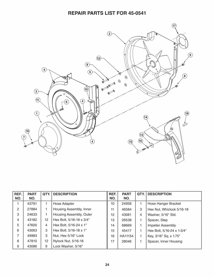
REPAIR PARTS LIST FOR 45-0541
REF. NO.
PART NO. QTY. DESCRIPTION
1 48791 1 Cart Tray2 65518 1 Rope, 36"3 43012 4 Hex Bolt, 1/4-20 x 3/4"4 24386 1 Latch Stand Plate5 43182 8 Hex Bolt, 5/16-18 x 3/4"6 26008 1 Axle7 40880 2 Wheel8 25748 1 Rear Tongue9 24527 1 Wheel Support10 24497 1 Latch Stand Bracket11 25742 1 Front Tongue12 23475 1 Hitch Bracket13 25010 1 Latch Lock Lever14 HA20186 1 Spring
REF. NO.
PART NO. QTY. DESCRIPTION
15 25875 2 Cart Bed Brace16 25910 2 Axle Clip17 47189 4 Nylock Nut, 1/4-2018 47810 9 Nylock Nut, 5/16-1819 R19212016 4 Washer, 5/8"20 43010 2 Cotter Pin21 23353 1 Hitch Pin22 43001 2 Hex Bolt, 3/8-16 x 1"23 HA21362 5 Nylock Nut, 3/8-1624 43343 1 Hair Cotter Pin, 3/32"25 43574 3 Hex Bolt, 3/8-16 x 3"26 47407 1 Hex Bolt, 5/16-18 x 4"27 M84309 8 Nut, Retainer
6
16719
20
17
9
6
10
12
53
2
1
15
18
8
4
21
13
26
2323
14
18
2211
25
25
2423
27

22
40
1
17
23
2214
11
58
13
8
13
13
8
26
2626
26
26
25
25
25
25
27
27
27
1010
10 34
32
3334
35
41
36
ADAPTER #62468
13
20 21
2825
25
4
37
3
12
18
12
31
18
3
2
28
31
6
16
15
9
839
7
2926
13
24 3038
39
31
25
19
See page 24
18
4
42
43
3128
44
45
46
REPAIR PARTS FOR MODEL 45-0541

23
REPAIR PARTS FOR MODEL 45-0541
REF. NO.
PART NO. QTY. DESCRIPTION
1 27144 1 Top Support Angle
2 25874 1 Front Support Tube
3 25876 2 Brace
4 49873 2 Lower Support Rod
5 43840 2 Hex Bolt, 5/16-18 x 1-1/4"
6 42479 1 Cart Cover
7 – 1 Engine
8 47810 7 Nylock Nut, 5/16-18
9 25873 1 Engine Mounting Base
10 43661 4 Hex Bolt, 1/4-20 x 1"
11 43791 1 Hose Adapter
12 43012 6 Hex Bolt, 1/4-20 x 3/4"
13 47189 5 Nylock Nut, 1/4-20
14 41882 1 Hose
15 49974 1 Hose Hanger Rod
16 46420 1 Elbow with Deflector
17 49983 3 Nut, Hex 5/16 Lock
18 43013 6 Lock Nut, 1/4-20
19 48402 2 Plug, Plastic
20 44850 2 Tarp Strap
21 44849 2 "S" Hook
22 43793 2 Hose Clamp
23 43790 1 Tarp Strap, 25"
24 43574 2 Hex Bolt, 3/8-16 x 3"
REF. NO.
PART NO. QTY. DESCRIPTION
25 43088 11 Washer, 1/4" Std.
26 1543-69 9 Nylon Washer
27 43081 12 Washer, 5/16" Std.
28 1509-90 7 Hex Bolt, 1/4-20 x 1-1/4"
29 47630 4 Hex Bolt, 5/16-18 x 3/4"
(Thread Forming)
30 43001 2 Hex Bolt, 3/8-16 x 1"
31 47598 11 Nut, Hex Flange 1/4-20
32 43830 1 Deck Adapter
33 23560 1 Deck Adapter Bracket
34 43080 2 Carriage Bolt, 5/16" x 3/4"
35 23825 1 Mounting Strap
36 23826 1 Angle Bracket
37 49872 1 Front Support Rod
38 43085 4 Hex Bolt, 5/16-18 x 1-1/2"
39 HA21362 4 Nylock Nut, 3/8-16
40 62468 1 Deck Adapter Kit
41 23827 1 Mounting Bracket
42 44950 5 Carriage Bolt, 1/4-20 x 3/4"
43 41518 5 Tinnerman Nut, 1/4-20
44 42749 1 "S" Hook, Large
45 27304 1 Bracket, Attachment
46 43086 3 Lock Washer, 5/16"
45446 1 Owner's Manual
24
REF. NO.
PART NO.
QTY. DESCRIPTION
1 43791 1 Hose Adapter
2 27884 1 Housing Assembly, Inner
3 24633 1 Housing Assembly, Outer
4 43182 12 Hex Bolt, 5/16-18 x 3/4"
5 47600 4 Hex Bolt, 5/16-24 x 1"
6 43063 3 Hex Bolt, 5/16-18 x 1"
7 49983 3 Nut, Hex 5/16" Lock
8 47810 12 Nylock Nut, 5/16-18
9 43086 9 Lock Washer, 5/16"
REF. NO.
PART NO.
QTY. DESCRIPTION
10 24958 1 Hose Hanger Bracket
11 46584 3 Hex Nut, Whizlock 5/16-18
12 43081 4 Washer, 5/16" Std.
13 26538 1 Spacer, Step
14 68669 1 Impeller Assembly
15 45417 1 Hex Bolt, 5/16-24 x 1-3/4"
16 HA11154 1 Key, 3/16" Sq. x 1.75"
17 28046 1 Spacer, Inner Housing
REPAIR PARTS LIST FOR 45-0541
22
25
3
5
824
4
3
116
10
8
14
104 15
13
16
4
9
2 9
212
10
7
1
17
25
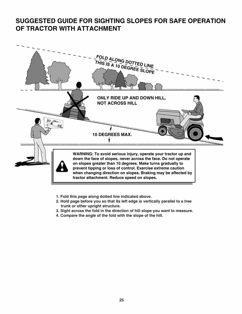
WARNING: To avoid serious injury, operate your tractor up and down the face of slopes, never across the face. Do not operate on slopes greater than 10 degrees. Make turns gradually to prevent tipping or loss of control. Exercise extreme caution when changing direction on slopes. Braking may be affected by tractor attachment. Reduce speed on slopes.
1. Fold this page along dotted line indicated above.2. Hold page before you so that its left edge is vertically parallel to a tree trunk or other upright structure.3. Sight across the fold in the direction of hill slope you want to measure.4. Compare the angle of the fold with the slope of the hill.
ONLY RIDE UP AND DOWN HILL,NOT ACROSS HILL
FOLD ALONG DOTTED LINETHIS IS A 10 DEGREE SLOPE
10 DEGREES MAX.
SUGGESTED GUIDE FOR SIGHTING SLOPES FOR SAFE OPERATIONOF TRACTOR WITH ATTACHMENT

26

27

PARTS ORDERING/SERVICE
the fastest way to purchase parts www.speedepart.com
REPAIR PARTSAgri-Fab, Inc.
809 South Hamilton Sullivan, IL. 61951
217-728-8388www.agri-fab.com
© 2017 Agri-Fab, Inc. PRINTED IN U.S.A.


![[XLS]saofranciscodoconde.ba.gov.brsaofranciscodoconde.ba.gov.br/wp-content/uploads/2014/02/... · Web view17175 2995856542 500 45446 276796594 500 70904 2545495514 500 1171 1385436581](https://img.pdfslide.net/doc/110x75/5af1320a7f8b9abc788e205c/xls-view17175-2995856542-500-45446-276796594-500-70904-2545495514-500-1171-1385436581.jpg)