Embed Size (px)
Citation preview
A. Pad Replacement - Full Hydraulic Systems and MX-1 Mechanical 1. Remove the wheel.
Note: It is not necessary to remove the caliper from the frame or fork, but it may make the installation of thenew pads easier if the caliper is removed.
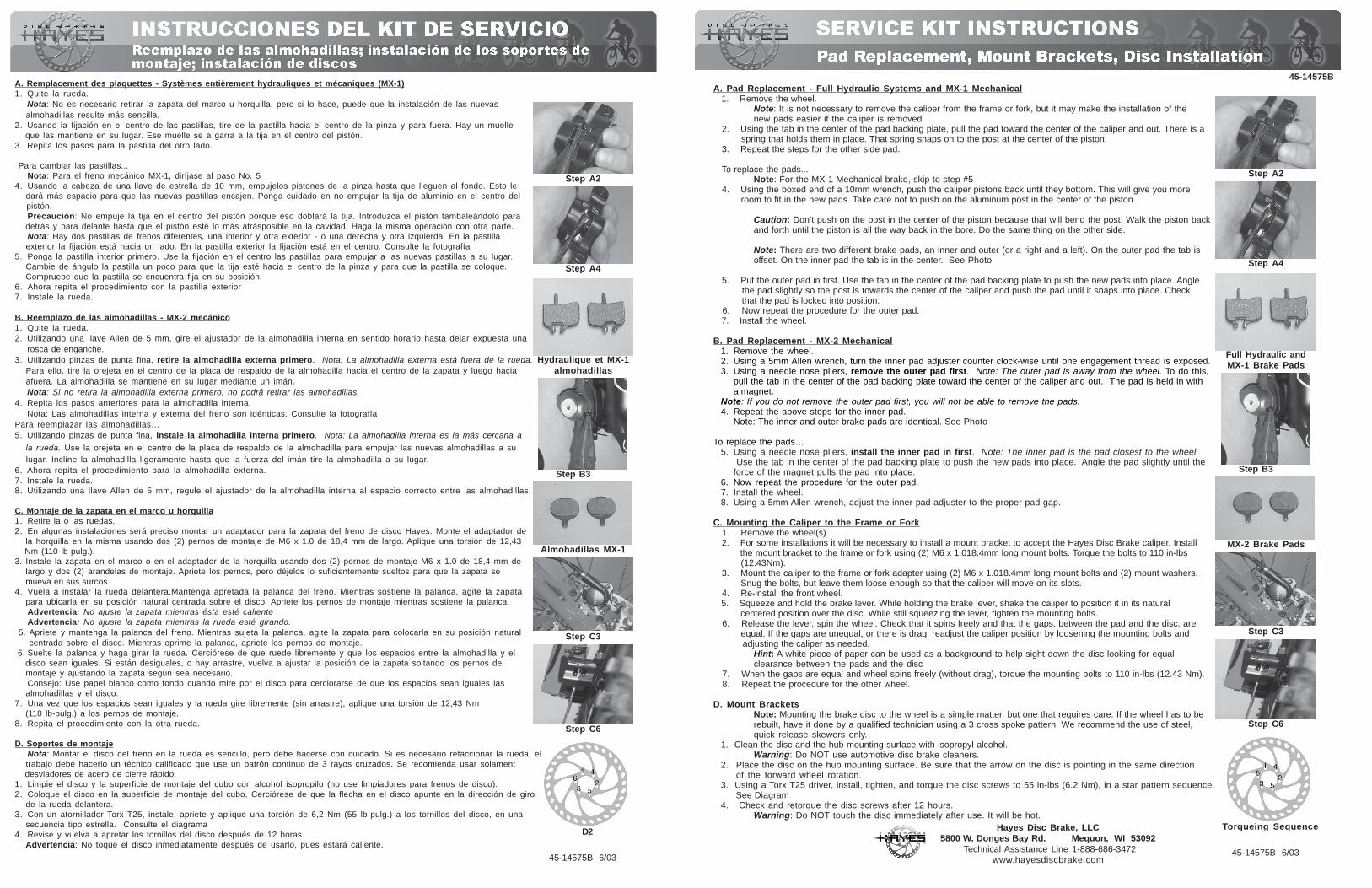
2. Using the tab in the center of the pad backing plate, pull the pad toward the center of the caliper and out. There is a spring that holds them in place. That spring snaps on to the post at the center of the piston. 3. Repeat the steps for the other side pad.
To replace the pads...Note: For the MX-1 Mechanical brake, skip to step #5
4. Using the boxed end of a 10mm wrench, push the caliper pistons back until they bottom. This will give you more room to fit in the new pads. Take care not to push on the aluminum post in the center of the piston.
Caution: Don’t push on the post in the center of the piston because that will bend the post. Walk the piston backand forth until the piston is all the way back in the bore. Do the same thing on the other side.
Note: There are two different brake pads, an inner and outer (or a right and a left). On the outer pad the tab isoffset. On the inner pad the tab is in the center. See Photo
5. Put the outer pad in first. Use the tab in the center of the pad backing plate to push the new pads into place. Angle the pad slightly so the post is towards the center of the caliper and push the pad until it snaps into place. Check that the pad is locked into position. 6. Now repeat the procedure for the outer pad. 7. Install the wheel.
B. Pad Replacement - MX-2 Mechanical1. Remove the wheel.2. Using a 5mm Allen wrench, turn the inner pad adjuster counter clock-wise until one engagement thread is exposed.3. Using a needle nose pliers, remove the outer pad first. Note: The outer pad is away from the wheel. To do this,
pull the tab in the center of the pad backing plate toward the center of the caliper and out. The pad is held in witha magnet.
Note: If you do not remove the outer pad first, you will not be able to remove the pads.4. Repeat the above steps for the inner pad.
Note: The inner and outer brake pads are identical. See Photo
To replace the pads…5. Using a needle nose pliers, install the inner pad in first. Note: The inner pad is the pad closest to the wheel.
Use the tab in the center of the pad backing plate to push the new pads into place. Angle the pad slightly until theforce of the magnet pulls the pad into place.
6. Now repeat the procedure for the outer pad.7. Install the wheel.8. Using a 5mm Allen wrench, adjust the inner pad adjuster to the proper pad gap.
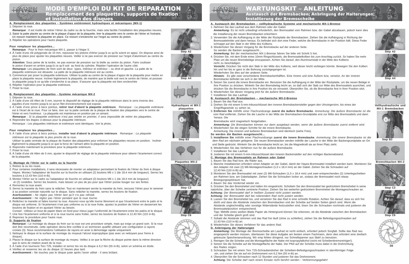
C. Mounting the Caliper to the Frame or Fork 1. Remove the wheel(s). 2. For some installations it will be necessary to install a mount bracket to accept the Hayes Disc Brake caliper. Install the mount bracket to the frame or fork using (2) M6 x 1.018.4mm long mount bolts. Torque the bolts to 110 in-lbs (12.43Nm). 3. Mount the caliper to the frame or fork adapter using (2) M6 x 1.018.4mm long mount bolts and (2) mount washers. Snug the bolts, but leave them loose enough so that the caliper will move on its slots. 4. Re-install the front wheel. 5. Squeeze and hold the brake lever. While holding the brake lever, shake the caliper to position it in its natural centered position over the disc. While still squeezing the lever, tighten the mounting bolts. 6. Release the lever, spin the wheel. Check that it spins freely and that the gaps, between the pad and the disc, are equal. If the gaps are unequal, or there is drag, readjust the caliper position by loosening the mounting bolts and adjusting the caliper as needed.
Hint: A white piece of paper can be used as a background to help sight down the disc looking for equalclearance between the pads and the disc
7. When the gaps are equal and wheel spins freely (without drag), torque the mounting bolts to 110 in-lbs (12.43 Nm). 8. Repeat the procedure for the other wheel.
D. Mount BracketsNote: Mounting the brake disc to the wheel is a simple matter, but one that requires care. If the wheel has to berebuilt, have it done by a qualified technician using a 3 cross spoke pattern. We recommend the use of steel,quick release skewers only.
1. Clean the disc and the hub mounting surface with isopropyl alcohol.Warning: Do NOT use automotive disc brake cleaners.
2. Place the disc on the hub mounting surface. Be sure that the arrow on the disc is pointing in the same directionof the forward wheel rotation.
3. Using a Torx T25 driver, install, tighten, and torque the disc screws to 55 in-lbs (6.2 Nm), in a star pattern sequence. See Diagram4. Check and retorque the disc screws after 12 hours.
Warning: Do NOT touch the disc immediately after use. It will be hot.
Step C3
45-14575B
Hayes Disc Brake, LLC5800 W. Donges Bay Rd. Mequon, WI 53092
Technical Assistance Line 1-888-686-3472www.hayesdiscbrake.com
Step A2
Step A4
Full Hydraulic andMX-1 Brake Pads
Torqueing Sequence
Step C6
MX-2 Brake Pads
45-14575B 6/03
Step B3
A. Remplacement des plaquettes - Systèmes entièrement hydrauliques et mécaniques (MX-1)1. Quite la rueda.
Nota: No es necesario retirar la zapata del marco u horquilla, pero si lo hace, puede que la instalación de las nuevas almohadillas resulte más sencilla.2. Usando la fijación en el centro de las pastillas, tire de la pastilla hacia el centro de la pinza y para fuera. Hay un muelle que las mantiene en su lugar. Ese muelle se a garra a la tija en el centro del pistón.3. Repita los pasos para la pastilla del otro lado.
Para cambiar las pastillas...Nota: Para el freno mecánico MX-1, diríjase al paso No. 5
4. Usando la cabeza de una llave de estrella de 10 mm, empujelos pistones de la pinza hasta que lleguen al fondo. Esto le dará más espacio para que las nuevas pastillas encajen. Ponga cuidado en no empujar la tija de aluminio en el centro del pistón.
Precaución: No empuje la tija en el centro del pistón porque eso doblará la tija. Introduzca el pistón tambaleándolo para detrás y para delante hasta que el pistón esté lo más atrásposible en la cavidad. Haga la misma operación con otra parte.
Nota: Hay dos pastillas de frenos diferentes, una interior y otra exterior - o una derecha y otra izquierda. En la pastilla exterior la fijación está hacia un lado. En la pastilla exterior la fijación está en el centro. Consulte la fotografía5. Ponga la pastilla interior primero. Use la fijación en el centro las pastillas para empujar a las nuevas pastillas a su lugar. Cambie de ángulo la pastilla un poco para que la tija esté hacia el centro de la pinza y para que la pastilla se coloque. Compruebe que la pastilla se encuentra fija en su posición.6. Ahora repita el procedimiento con la pastilla exterior7. Instale la rueda.
B. Reemplazo de las almohadillas - MX-2 mecánico1. Quite la rueda.2. Utilizando una llave Allen de 5 mm, gire el ajustador de la almohadilla interna en sentido horario hasta dejar expuesta una rosca de enganche.3. Utilizando pinzas de punta fina, retire la almohadilla externa primero. Nota: La almohadilla externa está fuera de la rueda. Para ello, tire la orejeta en el centro de la placa de respaldo de la almohadilla hacia el centro de la zapata y luego hacia afuera. La almohadilla se mantiene en su lugar mediante un imán.
Nota: Si no retira la almohadilla externa primero, no podrá retirar las almohadillas.4. Repita los pasos anteriores para la almohadilla interna.
Nota: Las almohadillas interna y externa del freno son idénticas. Consulte la fotografíaPara reemplazar las almohadillas…5. Utilizando pinzas de punta fina, instale la almohadilla interna primero. Nota: La almohadilla interna es la más cercana a
la rueda. Use la orejeta en el centro de la placa de respaldo de la almohadilla para empujar las nuevas almohadillas a su lugar. Incline la almohadilla ligeramente hasta que la fuerza del imán tire la almohadilla a su lugar.6. Ahora repita el procedimiento para la almohadilla externa.7. Instale la rueda.8. Utilizando una llave Allen de 5 mm, regule el ajustador de la almohadilla interna al espacio correcto entre las almohadillas.
C. Montaje de la zapata en el marco u horquilla1. Retire la o las ruedas.2. En algunas instalaciones será preciso montar un adaptador para la zapata del freno de disco Hayes. Monte el adaptador de la horquilla en la misma usando dos (2) pernos de montaje de M6 x 1.0 de 18,4 mm de largo. Aplique una torsión de 12,43 Nm (110 lb-pulg.).3. Instale la zapata en el marco o en el adaptador de la horquilla usando dos (2) pernos de montaje M6 x 1.0 de 18,4 mm de largo y dos (2) arandelas de montaje. Apriete los pernos, pero déjelos lo suficientemente sueltos para que la zapata se mueva en sus surcos.4. Vuela a instalar la rueda delantera.Mantenga apretada la palanca del freno. Mientras sostiene la palanca, agite la zapata para ubicarla en su posición natural centrada sobre el disco. Apriete los pernos de montaje mientras sostiene la palanca.
Advertencia: No ajuste la zapata mientras ésta esté calienteAdvertencia: No ajuste la zapata mientras la rueda esté girando.
5. Apriete y mantenga la palanca del freno. Mientras sujeta la palanca, agite la zapata para colocarla en su posición natural centrada sobre el disco. Mientras oprime la palanca, apriete los pernos de montaje. 6. Suelte la palanca y haga girar la rueda. Cerciórese de que ruede libremente y que los espacios entre la almohadilla y el disco sean iguales. Si están desiguales, o hay arrastre, vuelva a ajustar la posición de la zapata soltando los pernos de montaje y ajustando la zapata según sea necesario.
Consejo: Use papel blanco como fondo cuando mire por el disco para cerciorarse de que los espacios sean iguales las almohadillas y el disco.7. Una vez que los espacios sean iguales y la rueda gire libremente (sin arrastre), aplique una torsión de 12,43 Nm (110 lb-pulg.) a los pernos de montaje.8. Repita el procedimiento con la otra rueda.
D. Soportes de montajeNota: Montar el disco del freno en la rueda es sencillo, pero debe hacerse con cuidado. Si es necesario refaccionar la rueda, el
trabajo debe hacerlo un técnico calificado que use un patrón continuo de 3 rayos cruzados. Se recomienda usar solament desviadores de acero de cierre rápido.1. Limpie el disco y la superficie de montaje del cubo con alcohol isopropilo (no use limpiadores para frenos de disco).2. Coloque el disco en la superficie de montaje del cubo. Cerciórese de que la flecha en el disco apunte en la dirección de giro de la rueda delantera.3. Con un atornillador Torx T25, instale, apriete y aplique una torsión de 6,2 Nm (55 lb-pulg.) a los tornillos del disco, en una secuencia tipo estrella. Consulte el diagrama4. Revise y vuelva a apretar los tornillos del disco después de 12 horas. Advertencia: No toque el disco inmediatamente después de usarlo, pues estará caliente.
Step C3
Step A2
Step A4
Hydraulique et MX-1almohadillas
D2
Step C6
Almohadillas MX-1
45-14575B 6/03
Step B3
A. Remplacement des plaquettes - Systèmes entièrement hydrauliques et mécaniques (MX-1)1. Déposer la roue.
Remarque : Il est inutile de retirer l’étrier du cadre ou de la fourche, mais cela facilite l’installation des plaquettes neuves.2. Saisir la patte placée au centre de la plaque d’appui de la plaquette, tirer la plaquette vers le centre de l’étrier et l’extraire. Un ressort maintient la plaquette en place. Ce ressort s’enclenche sur l’ergot au centre du piston.3. Répéter les opérations pour l’autre plaquette.
Pour remplacer les plaquettes...Remarque : Pour le frein mécanique MX-1, passer à l’étape 5.
4. À l’aide d’une clé polygonale de 10 mm, repousser les pistons d’étrier jusqu’à ce qu’ils soient en appui. On dispose ainsi deplus de place pour ajuster les plaquettes neuves. Veiller à ne pas exercer de pression sur l’ergot d’aluminium au centre dupiston.Attention: Sous peine de la tordre, ne pas exercer de pression sur la bielle au centre du piston. Faire coulisserle piston d’avant en arrière jusqu’à ce qu’il soit au fond du cylindre. Répéter l’opération de l’autre côté.Remarque: Les plaquettes de frein sont de deux types, intérieur et extérieur – ou droit et gauche. La patte de laplaquette extérieure est désaxée. La patte de la plaquette intérieure est au centre.
5. Commencer par poser la plaquette extérieure. Utiliser la patte au centre de la plaque d’appui de la plaquette pour mettre enplace la plaquette neuve. Incliner légèrement la plaquette, de manière que la bielle soit vers le centre de l’étrier, et pousserla plaquette jusqu’à ce qu’elle s’enclenche à sa place. S’assurer que la plaquette est bien enclenchée
6. Répéter l’opération pour la plaquette extérieure.7. Poser la roue.
B. Remplacement des plaquettes - Système mécanique MX-21. Déposer la roue.2. À l’aide d’une clé Allen de 5 mm, tourner le dispositif de réglage de la plaquette intérieure dans le sens inverse des aiguilles d’une montre jusqu’à ce qu’un filet d’enclenchement soit exposé.3. À l’aide d’une pince à becs pointus, retirer tout d’abord la plaquette extérieure. Remarque : La plaquette extérieure est à l’écart de la roue. Pour ce faire, tirer sur la patte centrale de la plaque de fixation des plaquettes vers le centre de l’étrier et vers l’extérieur. La plaquette est maintenue en position par un aimant.
Remarque : Si la plaquette extérieure n’est pas retirée en premier, il sera impossible de retirer les plaquettes.4. Reprendre les étapes ci-dessus pour la plaquette intérieure.
Remarque : Les plaquettes intérieure et extérieure sont identiques. Voir la photo.
Pour remplacer les plaquettes...5. À l’aide d’une pince à becs pointus, installer tout d’abord la plaquette intérieure. Remarque : La plaquette intérieure est la plaquette la plus proche de la roue.
Utiliser la patte centrale de la plaque de fixation des plaquettes pour enfoncer les plaquettes neuves en position. Incliner légèrement la plaquette jusqu’à ce que la force de l’aimant attire la plaquette en position.6. Reprendre maintenant la procédure pour la plaquette extérieure.7. Poser la roue.8. À l’aide d’une clé Allen de 5 mm, ajuster le dispositif de réglage de la plaquette intérieure pour obtenir l’écartement correct de la plaquette.
C. Montage de l’étrier sur le cadre ou la fourche1. Retirez la ou les roues.2. Pour certaines installations, il sera nécessaire de monter un adaptateur permettant la fixation de l’étrier du frein à disque
Hayes. Montez l’adaptateur de fourche sur la fourche en utilisant (2) boulons M6 x 1 (de 18,4 mm de longueur). Serrez lesboulons à 12,43 Nm (110 in-lb).
3. Montez l’étrier sur le cadre ou l’adaptateur de fourche en utilisant (2) boulons M6 x 1 (de 18,4 mm de longueur) et (2) rondelles. Serrez les boulons, mais laissez un peu de jeu pour que l’étrier puisse bouger sur ses fentes.
4. Remontez la roue avant.5. Serrez la manette du frein sans la relâcher. Tout en maintenant serrée la manette du frein, secouez l’étrier pour le ramener
à sa position centrale naturelle sur le disque. Sans relâcher la manette, serrez les boulons de fixation.Avertissement : Ne réglez pas l’étrier tant qu’il n’a pas refroidi.Avertissement : Ne réglez pas l’étrier pendant que la roue tourne.
6. Relâchez la manette et faites tourner la roue. Assurez-vous qu’elle tourne librement et que l’écartement entre le patin et ledisque est uniforme. Si l’écartement n’est pas uniforme ou si la roue frotte, ajustez la position de l’étrier en desserrant lesboulons de fixation et en ajustant l’étrier au besoin.Conseil : Utilisez un bout de papier blanc en fond pour mieux juger l’uniformité de l’écartement entre les patins et le disque.
7. Une fois l’écartement uniforme et si la roue tourne sans frotter, serrez les boulons de fixation à 12,43 Nm (110 in-lb).8. Reprenez la procédure pour l’autre roue.D. Supports de fixation
Remarque : Le montage du disque du frein sur la roue est une procédure simple, mais qui exige un grand soin. Si la rouedoit être reconstruite, cette opération devra être confiée à un technicien qualifié utilisant une configuration à rayonscroisés (3). Nous recommandons l’utilisation de rayons en acier à démontage rapide uniquement.
1. Nettoyez le disque et la surface de montage du moyeuà l’alcool isopropylique (pas avec un nettoyant pour freins àdisque).
2. Placez le disque sur la surface de montage du moyeu. Veillez à ce que la flèche du disque pointe dans la même directionque le sens de rotation avant de la roue.
3. À l’aide d’un tournevis Torx T25, installez et serrez les vis du disque à 6,2 Nm (55 in-lb), selon un schéma en étoile.4. Vérifiez et resserrez les vis du disque 12 heures plus tard.
Avertissement : Ne touchez pas le disque juste après l’avoir utilisé - il sera brûlant.
Step C3
Step A2
Step A4
Hydrauliques et MX-1plaquettes
D3
Step C6
Plaquettes MX-2
Step B3
A. Austausch der Bremsbacken – vollhydraulische Systeme und mechanische MX-1-Bremse1. Nehmen Sie das Laufrad aus dem Rahmen oder der Gabel.
Anmerkung: Es ist nicht unbedingt erforderlich, den Bremssattel vom Rahmen bzw. der Gabel abzubauen, jedoch kann dies die Installierung der neuen Bremsbacken erleichtern.2. Verwenden Sie die Aufhängung in der Mitte der Rückplatte der Bremsbacken. Ziehen Sie die Aufhängung in Richtung der
Bremssattelmitte und dann heraus. Es befindet sich dort eine Feder, welche die Bremsbacke in der Position hält. Diese Federschnappt auf den Stab in der Mitte des Kolbens.
3. Wiederholen Sie diesen Vorgang für die Bremsbacke auf der anderen Seite. So werden die Backen ausgetauscht…
Anmerkung: Bei der mechanischen MX-1-Bremse fahren Sie bitte mit Schritt 5 fort.4. Drücken Sie, mit dem Ende eines 10mm Ringschlüssels, die Bremssattelkolben bis zum Anschlag zurück. So haben Sie mehr
Platz um die neuen Bremsbeläge einzupassen. Achten Sie darauf, den Aluminiumstab in der Mitte des Kolbensnicht zu beschädigen.Vorsicht: Drücken Sie nicht den Stab in der Mitte des Kolbens, weil dieser leicht verbiegen könnte. Bewegen Sie den Kolbenhin und her bis er ganz in die Bohrung zurückgegangen ist.Wiederholen Sie dies auf der anderen Seite.Hinweis: Es gibt zwei verschiedene Bremsbackenhälften. Eine Innere und eine Äußere bzw. versetzt. An der innerenBremsbacke befindet sie sich in der Mitte.
5. Setzen Sie zuerst die innere Bremsbacke ein. Benutzen Sie die Aufhängung in der Mitte der Rückplatte, um die neuen Beläge inihre Position zu drücken. Winkeln Sie den Bremsbelag leicht an, so daß sich der Stab zur Mitte des Bremssattels ausrichtet, unddrücken Sie die Bremsbacke in ihre Position bis sie einrastet. Überprüfen Sie, ob die Bremsbacke fest in ihrer Position sitzt.
6. Wiederholen Sie diesen Vorgang jetzt für die äußere Bremsbacke.7. Installieren Sie das Laufrad.B. Austausch der Bremsbacken – mechanische MX-2-Bremse1. Bauen Sie das Rad aus.2. Drehen Sie mit einem 5-mm-Inbusschlüssel den inneren Bremsbackensteller gegen den Uhrzeigersinn, bis eines der Eingriffsgewinde zu sehen ist.3. Entfernen Sie mithilfe einer Flachrundzange zuerst die äußere Bremsbacke. Anmerkung: Die äußere Bremsbacke ist die vom Rad entfernte. Ziehen Sie die Lasche in der Mitte der Bremsbacken-Grundplatte erst zur Mitte des Bremssattels und dann heraus. Die Bremsbacke wird magnetisch festgehalten.
Anmerkung: Die Bremsbacken können nur dann ausgebaut werden, wenn die äußere Bremsbacke zuerst entfernt wird.4. Wiederholen Sie die obigen Schritte für die innere Bremsbacke.
Anmerkung: Die inneren und äußeren Bremsbacken sind identisch (siehe Foto).So werden die Backen ausgetauscht…5. Installieren Sie mithilfe einer Flachrundzange zuerst die innere Bremsbacke. Anmerkung: Die innere Bremsbacke ist die dem Rad am nächsten gelegene. Die neuen Bremsbacken werden mithilfe der Lasche in der Mitte der Backengrundplatte an Ort und Stelle gedrückt. Winkeln Sie die Bremsbacke leicht an, bis die Magnetkraft sie an ihren Platz zieht.6. Wiederholen Sie das Verfahren nun für die äußere Bremsbacke.7. Installieren Sie das Laufrad.8. Justieren Sie mit einem 5-mm-Inbusschlüssel den inneren Backensteller auf den richtigen Backenabstand.C. Montage des Bremssattels an Rahmen oder Gabel1. Bauen Sie das Rad bzw. die Räder aus.2. Manche Installationen erfordern einen Adapter an der Gabel, damit der Hayes-Bremssattel installiert werden kann. Montieren Sie
den Adapter mit zwei (2) M6-Montageschrauben (1,0 x 18,4 mm) an der Gabel. Ziehen Sie die Schrauben auf12,43 Nm (110 in-lb) an.
3. Montieren Sie den Bremssattel mit zwei (2) M6-Schrauben (1,0 x 18,4 mm) und zwei entsprechenden (2) Unterlegscheibenam Rahmen bzw. am Gabeladapter. Ziehen Sie die Schrauben locker an, sodass der Bremssattel noch etwasBewegungsspielraum hat.
4. Bauen Sie das Vorderrad wieder ein.5. Drücken Sie den Bremshebel und halten ihn eingedrückt. Schütteln Sie den Bremssattel bei gedrücktem Bremshebel in seinenatürliche, über der Scheibe zentrierte Position. Ziehen Sie bei weiterhin gedrücktem Bremshebel die Montageschrauben an.Achtung: Der Bremssattel darf in heißem Zustand nicht justiert werden.Achtung: Der Bremssattel darf bei rotierendem Rad nicht justiert werden.6. Lassen Sie den Bremshebel los, und versetzen Sie das Rad in eine schnelle Rotation. Achten Sie darauf, dass es sich frei
dreht und dass die Abstände zwischen den Bremsbacken und der Scheibe auf beiden Seiten gleich sind. Wenn dieAbstände ungleichmäßig oder sonstige Widerstände festzustellen sind, lösen Sie die Schrauben nochmals und justieren dieBremssattelposition entsprechend.Tipp: Mithilfe eines weißen Blatts Papier als Hintergrund können Sie erkennen, ob die Abstände zwischen den Bremsbackenund der Scheibe gleich groß sind.
7. Sobald die Abstände stimmen und das Rad frei läuft (ohne zu schleifen), ziehen Sie die Befestigungsschrauben auf12,43 Nm (110 in-lb) an.
8. Wiederholen Sie dieses Verfahren für das andere Rad.D. Anbringung der Halterungen
Anmerkung: Die Montage der Bremsscheibe am Laufrad ist recht einfach, erfordert jedoch Sorgfalt. Sollte das Rad neueingespeicht werden müssen, überlassen Sie diese Aufgabe am besten einem Fachmann, denn dies erfordert eine dreifachgekreuzte Speichenanordnung. Wir emp fehlen dringend, nur Schnellspanner aus Stahl zu benutzen.
1. Reinigen Sie die Scheibe und die Montagefläche der Nabe mit Isopropylalkohol (nicht mit Scheibenbremsreiniger!).2. Setzen Sie die Scheibe auf die Montagefläche der Nabe. Der Pfeil auf der Scheibe muss dabei in die Drehrichtung
des Rades zeigen.3. Schrauben Sie mit einem Torx T25-Schraubendreher die Scheiben-Befestigungsschrauben in sternförmiger Folge
ein, und ziehen Sie sie auf ein Drehmoment von 6,2 Nm (55 in-lb) an.4. Überprüfen Sie die Schrauben nach 12 Stunden und justieren Sie das Drehmoment.
Achtung: Die Scheibe darf nach einem Einsatz nicht berührt werden - Verbrennungsgefahr!
Step C3
Step A2
Step A4
Vollhyudraulische undMX-1 Bremsbacken
D3
Step C6
Bremshbacken MX-2
Step B3


![CHAPITRE PLAQUETTES INDEXABLES CBN & PCD · plaquettes indexables cbn pour le tournage plaquettes indexables cbn pour le tournage [nÉgatives] neg plaquettes indexables avec trou](https://img.pdfslide.net/doc/110x75/5b991c0309d3f219118d4d87/chapitre-plaquettes-indexables-cbn-pcd-plaquettes-indexables-cbn-pour-le-tournage.jpg)