Embed Size (px)
Citation preview

AD-AU91 452 SCHNABEL ENGINEERING ASSOCIATES RICHMOND VA F/G 13/13
NATIONAL DAM SAFETY PROGRAM. UPPER OCCOQUAN REGIONAL WATER RECL--ETC(U)SEP 80 R E MARTIN OACW6S-79-D-0004
UNCLASSIFIED
EllEEEEEEIElll
....I..IIIIIIIIIIIIIIIIIIIIIIhIEIEEEIIIIIIIIIIIII
1 11 .0 L I 8 j 0
1 1.41 .1..
MICROCOPY RESOLUTION TEST CHARTNATIONAL BUREAU OF STANDARDS-1963-A
2" t4n.ai T.arn Sat. Pr -rW)mOf Dom:4
hWubr NuuWer VAW 1692
PHAE, ISPECTION REPORTNATIONAL DAM 'SFETY PROGRAM
4t1
Jr.,A
NORPOLX DISTRICr CORP OF UNGNMRf~ , 603 FRONT STRW
NORFOLK, V*INIA 23510
8s 80 1030 073~
*IM J. X.c7"Mm = _______8~~#4 "s iw6 _ _ _ _ _ _
~'4t

DISCLAIMER NOTICE
THIS DOCUMENT IS BEST QUALITYPRACTICABLE. THE COPY FURNISHEDTO DTIC CONTAINED A SIGNIFICANTNUMBER OF PAGES WHICH DO NOTREPRODUCE LEGIBLY.
.
Lii
'.. . ."

SECURITY CLASSIFICATION4 OF THIS PAGE PAGE Date INSTRCTION
REPOR DOCMENTTIONBEFORE COMPLETING FORM1REPORT NUMUER 2. GOVT ACCESSION NO. S. RECIPIENT'S CATALOG NUMBER
VA 05924y4. TIT LE (md SubtUie) S. TYPE OF REPORT &PERIOD COVERED
Phase I Inspect ion ReportNational Dam Safety Program FinalUpper Occoquan Regional Water Reclamation Plant 7* PERFORMING ORG. REPORT NUMBERvDam - Fairfax Countv, Virginia
7. AUTHORtfq) 8- S CONTRACT ORt GRANT MNMBIER(.)Schnabel Engineerinst Associates, P.C./J. K. Timmons and Associates, Inc. /DACW 65-79-1-0004
3. PERFORMING ORGANIZATION NAME AND ADDRESS 10. PROGRAM ELEMENT PROJECT. TASKAREA * WORK UNIT NUMBERS
ICONTROLLING OFFICE NAME AND ADDRESS 12. REPORT DATEU. S. Armv Enstineering District, Norfolk September 1980803 Front Street 13. NUMBER OF PAGESNorfolk, Virginia 23510
14. MONI1TORING AENCY NAMIE a AODRESS(i1 different imm CmmtmVlhhU Office) IS. SECURITY CLASS. (of this ,port)
Unclassified150. DECLASSIFICATION/DONGRADING
SCHEDULE
I0. DISTRIBUTION STATEMENT (of tm, Repot)
Approved for public release; distribution unlimited.
17. DISTRIBUTION STATEMENT (of het obodect anteied In Block ". if dIflwumt hown Xeport)
OIL. SUPPLEMENTARY NO IES
Copies are obtainable from National Technical Information Service,Ni" Springfield, Virginia 22151
Dams -VANational Dam Safety Proaram PhaseIDam SafetyDam Inspect ion
(See reverse side)
Do , 13 33911C oF I NOV6at IS OBOLIETE Unclassified
StCURI11TV CLASSIFICATfOS OF THIS5 PAGE (Men Dole Rnfero*

r SECUIUTY CLASSIFICATION OF THIS PAeIPSm Del. Xneie
20. Abstract
Pursuant to Public Law 92-367, Phase I Inspection Reports are preparedunder guidance contained in the recommended guidelines for safetyinspection of dams, published by the Office of Chief of Engineers,Washington, D. C. 20314. The purpose of a Phase I investigation is toidentify expeditiously those dams which may pose hazards to human life orproperty. The assessment of the general conditions of the dam is basedupon available data and visual inspections. Detailed investigation andanalyses involving topographic mapping, subsurface investigations,testing, and detailed computational evaluations are beyond the scope of aPhase I investigation; however, the investigation is intended to identifyany need for such studies.
Based upon the field conditions at the time of the field inspection andall available engineering data, the Phase I report addresses thehydraulic, hydrologic, geologic, geotechnic, and structural aspects ofthe dam. The engineering techniques employed give a reasonably accurateassessment of the conditions of the dam. It should be realized thatcertain engineering aspects cannot be fully analyzed during a Phase Iinspection. Assessment and remedial measures in the report include the
requirements of additional indepth study when necessary.
Phase I reports include project information of the dam and appurtenances,all existing engineering data, operational procedures,hydraulic/hydrologic data of the watershed, dam stability, visual
inspection report and an assessment including required remedial measures.
SECUOITY CLASSIFICATION OF THIS PAGErWhe Date sa
4

This report is prepared under guidance contained in the Re-ommended Guidelines for Safety Inspection of Dans, for Phase IInvestigations. Copies of these guidelines may be obtained fromthe Office of Chief of Engineers, Washington, D. C., 20314. Thepurpose of a Phase I Investigation is to identify expeditiouslythose dans which may pose hazards to human life or property. Theassessment of the general condition of the dam is based upon availabledata and visual inspections. Detailed investigation, and analysesinvolving topographic mapping, subsurface investigations, testing, anddetailed caqxtationa1 evaluations are beyond the scope of a Phase IInvestigation; however, the investigation is intended to identifyany need for such studies.
In reviewing this report, it should be realized that thereported condition of the dam is based on observations of fieldconditions at the time of inspection along with data availableto the inspection tean. In cases where the reservoir was loweredor drained prior to inspection, such action, while improving thestability and safety of the dam, removes the normal load on thestructure and may obscure certain conditions which might otherwisebe detectable if inspected under the nonal operating environmentof the structure.
It is important to note that the condition of a dam dependson numerous and constantly changing internal and eternal conditions,and is evolutionary in nature. It would be incorrect to assume thatthe present crdition of the dam will continue to represent thecondition of the dam at sone point in the future. Only throughfrequent inspections can unsafe conditions be detected and onlythrough continued care and maintenance can these conditions beprevented or corrected.
Phase I inspections are not intended to provide detailedhydrologic and hydraulic analyses. In accordance with the establish-ed Guidelines, the Spillway Test flood is based on the estimated"Probable Maxinum Flood" for the region (greatest reasonably possible1 storm runoff), or fractions thereof. Because of the magnitude andrarity of such a stom event, a finding that a spillway will notpass the test flood should not be interpreted as necessarily posinga highly inadequate condition. The test flood provides a measureof relative spillway capacity and serves as an aide in determiningthe need for more detailed hydrologic and hydraulic studies, oon-sidering the size of the dam, its general cordition and the down-strea damage potential.
Sii

C-.. -e I, = , : . .w .. , , . .... .. -... . ... . , - , = '
A
TABLE OF OvrEmS.
Preface ...... ........ ...... . i
Brief Assessnt . . . . . . ..... . . . . . . .
S. e . '. . . . 3
" Section 1:PROW] IN DROMOIN .. 4
.Section 2% DATAEE.I1.E. . . . 8
Section 3: viSUA I!EEC1i-t o .. . .. U
Q-~ection 4: OPEPATINAL PJRO'UES ,. .. .. ... . 14
onctc 5: HYDPA&LIC/HYD!OtL=GC MMrA . . . . . . . 15
'Section 6: DAM S'BILrJY ............. 18
-Section 7: ASSESSM/FEDIAL MEASUES] . . . . . 22
I-ps and Drawings A ession For
b~ins GRA.&II - Photographs DDX TAB
:: Uaanounc edIII - Field Observations Justification
IV -perations S-ary
V - Piez meter Readi- .VI -RTeferences t,:I udo'
/01
6 echa

PHASE I REPORTNATICAL DAM SAFETY PROGRAM
BRIEF ASSESMEN OF DAM
Name of Dam: Upper Oooquan Regional Water ReclamationPlant Dam
State: VirginiaCounty: FairfaxUSGS Quad Sheet: ManassasStOredinates: Lat 380 48.3' Long 770 27.4'Stream: Branch of Bull RmDate of Inspection: 1 May, 1980
Upper Occoquan Regional Water Reblamation Plant Dan is a zoned
earthfil1 structure about 1680 ft long and 41 ft high. The principal
spillway consists of a 250 ft long concrete wair, which discharges into
a 20 ft wide by 10 ft deep conrrete discharge channel. Additional out-
let works include a valved 36 inch diameter iron pipe extending through
the embankment at the botto of the reservoir. The dam is an inter-
Nediate size structure and is assigned a "significant" hazard classifi-
cation. The dam is located on a branch of Bull Rm V mately two
miles north of Manassas Park, Virginia. The lake is used for the dilution
and storage of the wastewater treatment plant. effluent and is owned
- r and maintained by the Upper ooquan Sewage Authority.
Based on criteria established by the Department of the Anny,
Office of the Chief of Engineers (oCE), the appropriate Spillway
Design Flood (SDF) is the 1J PW or 200 percent of the SO . The
spillway is judged adequate.
I
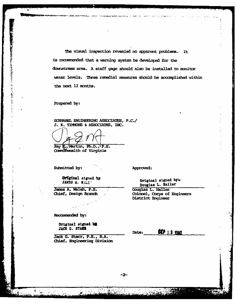
bThe visual inspection revealed no apparent problems. It
is recut ded that a warning system be developed for the
downstream area. A staff gage should also be installed to monitor
water levels. These remedial ueasures should be accomplished within
the nect 12 months.
Prepared by:
SC IMENGINERING ASSOCIATES, P.C./J. K. TIIN1S & ASSOCIATES, INC.
Ray . 1artin, Ph.D., P.E.Comwath of Virginia
SSubitted by. Approved:
Ordginal signed byJAXES A. W.'L$:" original signed b¥yuAS ILDouglas L. ailer
Jaues A. Walsh, P.E. Douglas L. HailerChief, Design Branch Colonel, Corps of Engineers
District Engineer
Reocimiedby:
Original signed beJACK G. STADate:
Jack G. Starr, P.E., R.A.Chief, Engineering Division
-2-

RESERVOIR AND TREA7MW~ PIAM1
-Ar o"-L--
OVJERVIEWJ OF DAM (UPSTEAM SLOPE)
1 MA.Y, 1980
General I PROJECr INEORt'TION1.1 General:
1.1.1 Autority: Public Law 92-367, 8 August 1972, authorizedi the Secretary of the Army through the Oorps of Engineers, to initiate
a national program of safety inspection of dams throughout the
United States. The Norfolk District has been assigned the respons-
ibility of supervising the inspection of dams in the Qxirealth
of Virginia.
1.1.2 Purpose of Inspection: The purpose is to conduct a
Phase I inspection according to the ecmended Guidelines for
Safety Inspection of Dams (see Reference 1, Appendix VI). The
main responsiblity is to expeditiously identify those dams which
nay be a potential hazard to human life or property.
1.2 Project Description:
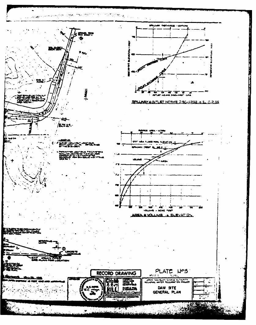
1.2.1 Dam and Apprtenanoes: Upper Occoquan Regional Water
Reclamation Plant Dam is a zoned earthfill structure approximately
1680 ft long and 41 ft high.* The top of the dam is 20 ft wide,
and side slopes are aprcimtely 4 horizontal to 1 vertical (4:1)
on the upstream and downstream sides of the dam. The top of the dam
is at elevation 195 mwl.
* Height is measured from the to of the dam to the downstream streamtoe at the centerline of the stream.
-4'.
The dam is keyed into the foundation and there is an internal
drainage system with drain outlets. Existing vegetation on the
downstream slope and riprap on the upstream slope provide embankment
protection.
The principal spillway consists of a 250 ft long by 6 ft high
reinforced concrete weir located at the right abutment. The weir
discharges into a 10 ft deep by 20 ft wide reinforced concrete
outlet channel, 480 ft in length. The weir crest is at elevation
188 ml. For low flow purposes the center 50 ft of the weir is at
elevation 187.5 msl (0.5 ft lower than the remainder of the weir).
A 24 inch diameter concrete pipe (invert elevation 179.0 msl) located
under the outlet channel, cxnveys water from the low flow weir to the
plunge -pol during low flow conditions.
For purposes of drawing off water from the reservoir at different
elevations in the event of thermal, nutrient or dissolved oxygen strat-
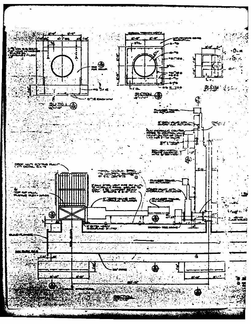
ification there is a separate outlet. The cutlet works consist of a
36 inch diameter hydraulically controlled intake structure with an invert
at elevation 161 msl, and 355 ft of 36 inch diameter ductile iron outlet
pipe discharging at an invert elevation of 155.5 msl. There are two
hydraulically activated circular pipe intakes and hydraulically operated
gates located adjacent to the intake structure. A 10 inch diameter in-
let is at centerline elevation 167.5 msl and an 8 inch inlet is located
at centerline elevation 177.5 msl, (see Plates No. 3, 5 through 7,
Appendix i).
-5-

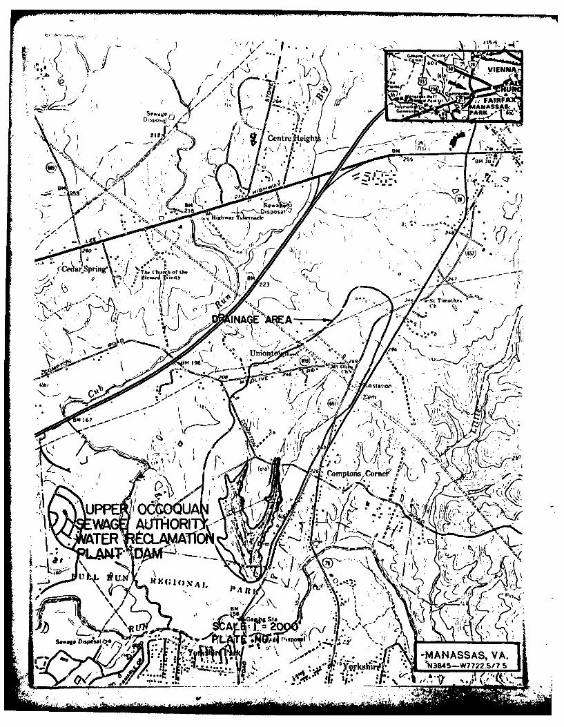
1.2.2 Location: Upper Occoquan Regional Water Reclamation
Plant Dam is located on a branch of Bull Run approximately two
miles north of Manassas Park, Virginia, (see Plate No. 1,
Appendix I).
1.2.3 Size Classification: The dam is classified as an
"intermediate" size structure because of its height and the maximn
lake storage potential.
1.2.4 Hazard Classification: The dam is located in a
suburban area, and based upon the proximity of several commercial
structures, located several miles downstream, the dam is assigned
a "significant" hazard classification. The hazard classification
used to categorize a dam is a function of location only and has
nothing to do with its stability or probability of failure.
1.2.5 Ownership: The dam is owned by the Upper Ocoquan
Sewage Authority (UOSA).
1.2.6 Purpose: Storage and dilution of wastewater treatment
plant effluent.
1.2.7 Design and Construction History: The dam was designed
and constructed under the supervision of CH2M-Hill, Consulting
Engineers, of Reston, Virginia. The structure was constructed by
Richard F. Kline, Inc. and completed in 1976.
1.2.8 Normal Operational Procedures: The principal spillway
is ungated, therefore, water rising above the crest of the weir
automatically is discharged downstream. Normal pool is maintained
-6-
_ - .N

slightly above the crest of the low 50 foot center portion of the
spillway (elevation 187.5). 'Above nornal flows rise above elevation
188 and u tilize the entire spillway in discharging water fron the reservoir.
1.3 Pertinent Data:
1.3.1 Drainage Area: The drainage area is 0.89 square miles.
1.3.2 Discharge at Dam Site: Acoording to Mr. Ed Wozniak (UOQS)
the maximu= flood at the dam sitehas not been observed.
Principal Spillway Discharge:
Pool Elevation at Crest of Dam (elev 195 ml) 9821 CFS
1.3.3 Dam and Reservoir Data: See Table 1.1, below:
Table 1. 1 - DAM AND RESERVOIR DATA
Reservoir
Storage
Elevation Volumefeet Area Acre Watershed length
Item msl Acres Feet Inches Miles
Crest of Dmu 195 75 1130 23.8 0.7
Principal SpillwayCrest 188 56 552 U.6 0.6
S Ft Center Section 187.5 54 515 10.85 0.6
Streatied at Do-stream Toe of Dam 154'
-7-
. , . _ ., .,
SECTION 2 - GINEERING D
2.1 Desi: The dam was designed and constructed under the
direction of H2P-Hill for the Upper Occoquan Sewage Authority.
Design data and operations records are available at the site.
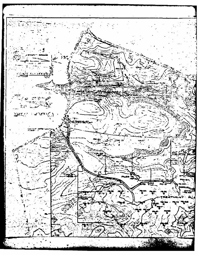
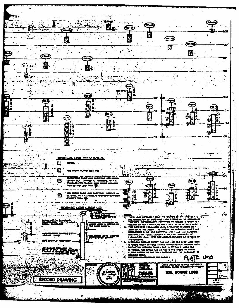
A subsurface investigation was conducted at the site by CHM-Hil1
during the initial design phase. The investigation consisted of
drilling test borings and excavating test pits at the locations shown
on Plate No. 2, Appendix I. Test boring and test pit logs are given
on Plate No. 8, Appendix I. Foundation recommendations were prepared
based upon the subsurface investigation and laboratory test data,
however, this information was not made available.
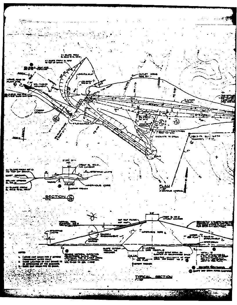
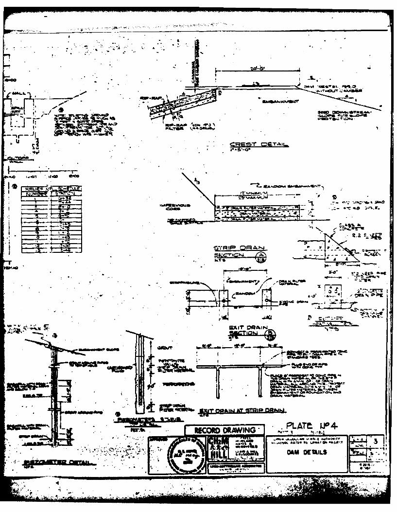
The dam is a zoned, compacted earthfill embankment (Plate No. 3,
Appendix I). Construction specifications required that the "impervious
core" be constructed with 'tmixtures of silt, clayey silt and dwxuposed
shale" with a mxinum particle size of 2 inches. The outer shell or
"randum embankment" consists of "silt, clayey silt, deamposed shale,
and shale". "Cobbles or boulders" included in this zone were not
to exceed 6 inches in size. Fill within both zones was to be acn-
pacted to a "minimum of 98 percent relative compaction" as defined
in the construction specifications. Lift thicknesses were not to
exceed. 6 inches following oapaction.
A review of design data indicates that most of the dam is
founded on decomposed shale and includes a cutoff trench which
extends into the deciposed shale. The only portion of the dam
founded on overburden soils is the downstream slope beyond the
strip drain. No field peneability test data was included in the
£.,, .- 8-

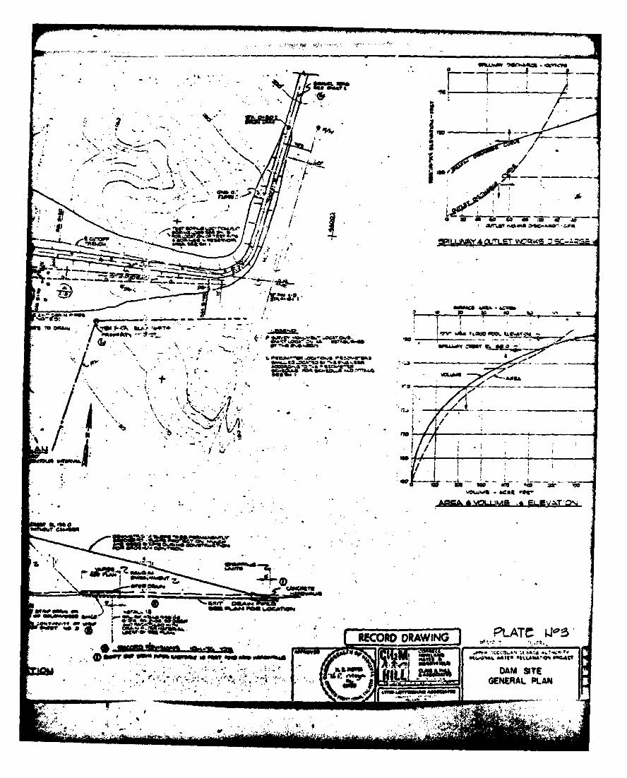
design data reviewed. Details of the cutoff trench are provided on
Plate No. 3, Appendix I.
An internal drainage system was constructed immediately down-
stream of the inpervious core in order to collect seepage, reduce
uplift pressures beneath the dam, and control the phreatic surface
within the erbankment. This systen consists of a sand and gravel
strip drain approxinately 925 ft long, 12 to 25 ft wide, and 3.5 ft
thick. Water is collected in 20 ft of 6 inch perforated concrete pipe
and exits through two 6 inch nonperforated concrete pipes into an
outlet channel. The 6 inch pipes are enclosed in an envelope of coarse
drain fill. Thirteen (13) 6 inch diameter relief wells, spaced on 50 ft
centers, were also constructed in conjunction with this system.
They extend 30 ft below the strip drain and have been backfilled with
filter material. Details of the drainage system are provided on
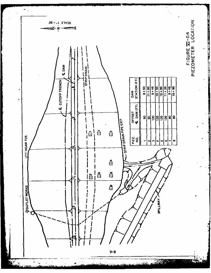
Plates No. 3 and 4 of Appendix I. Sixteen (16) piezmeters were also
installed at 8 locations along the downstream slope in order to
munitor pie!mutric levels within the dmmstrema wkment. Iocations and
construction design are provided on Plates No. 3 and 4, respectively
of Appendix 1.
The principal spillway consists of a 250 ft long and 6 ft high
reinforced concrete weir located at the right abubmntz. Tw weir
discharges into a 10 ft deep and 20 ft wide reinforced .'ete
channel. Design details are presented on Plate No. 5, Appwi I.
The outlet works consist of a 36 inch dimeter hydraulic ly
controlled intake structure and 355 ft of 36 inch ductile iron pipe,
* . -9-

which discharges into a riprap lined outlet chanrel. Five (5)
antiseep collars spaced on 30 ft centers were included to pre-
vent piping of embankment materials along the outlet pipes (see
Plates No. 6 and 7, Appendix I).
A stability analysis was reportedly perforIed for this strucre,
howeer, this information was not provided.
2.2 Construction: The construction records were not furnishd
but are available from the cH2M-Hill office in Reston, Virginia.
2.3 Evaluation: Engineering calculations are adequate and the
design drawings are representative of the dam. The operational pro-
cedure is consistant with the purpose of the dam, and employs sat-
isfactory methods of operation. There is sufficient information to
evaluate foundation conditions but not the eitankment stability.
. -10-
SaCTnuK 3 - IWPL WnC
3.1 Findings: At the time of inspection, the dam was in good
condition. Field observations are outlined in Appendix III.
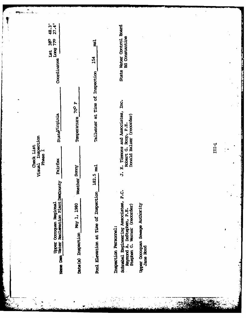
3.1.1 General: An inspection was muade 1 My 1980 and the
weather was sunny with a temperature of 700 F. The pool and tailwater
levels at the time of inspection were 182.5 and 154 msl, respectively.
This corresponds to a below nrmal pool elevation and normal tailwater
elevation. Ground conditimns were damp at the time of inspection. A
record of piezcueter readings and a recently cumpleted report on silt-
ation buildup in the reservoir were available during the inspection.
3.1.2 Dam and Spillway: To 6-inch concrete pipes from the outlet
for the foundation toe drain. No flow was observed frau the right pipe
with less than 1 gpm exiting fron the left. The downstream embank-
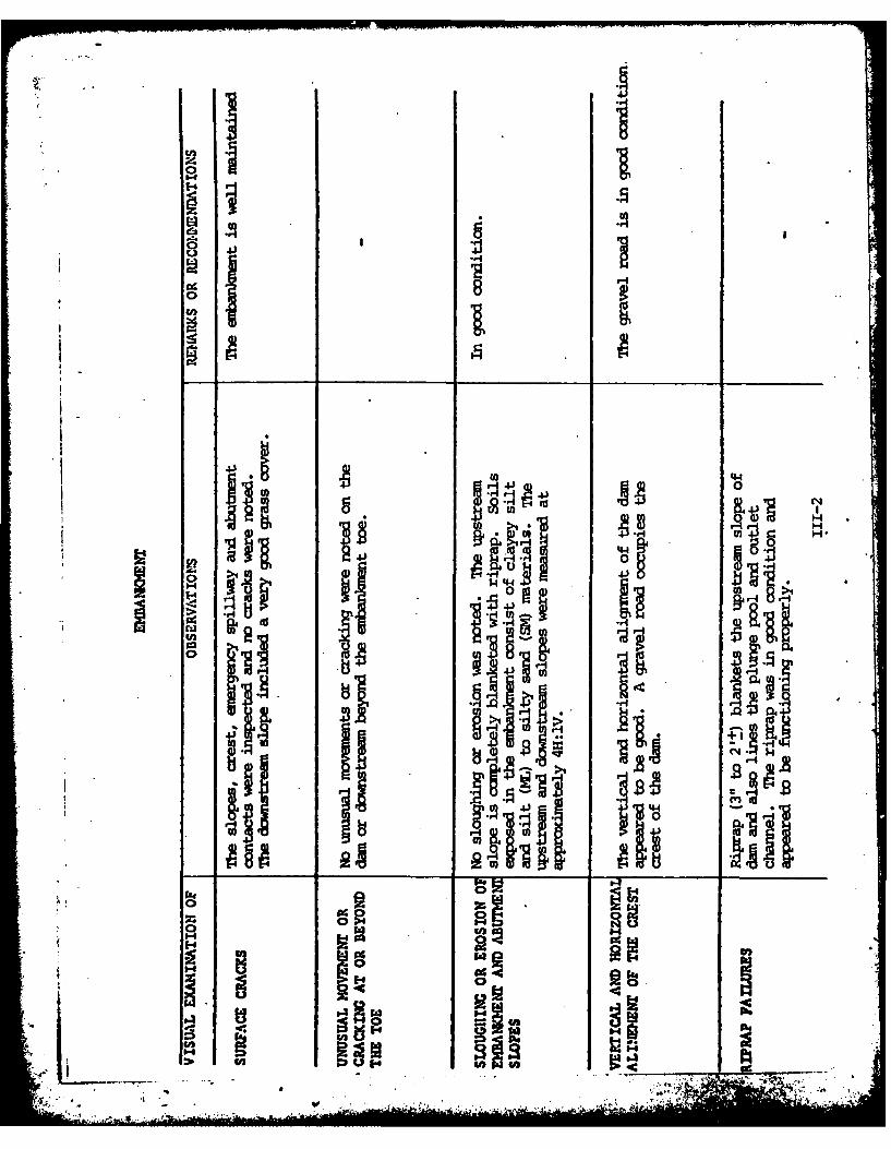
ment slope was grassed and the upstream slope was blanketed with riprap
with maxinum dimensions of about 2 ft± (Photo No. 2, Appendix II and Over-
view Photo of Dam, Page 3). The crest of the dan consists of a gravel road
(overview Photo of Dam, Page 3). Field measurements indicate both the up-
stream and downstream slopes are approximately 4H:IV. The dan appears to
be constructed with various combinations of sand and silt which visually
range frmu SH to ML in accordance with the Unified Soils Classification
System. No surface erosion was noted on the embankment slopes and no
seepage was observed along the downstreau toe.
Both abutments were well vegetated and the ahftnent-effbmnkmert
contacts were in good comition. Surface soils in the surrounding
area include clayey silt (ML) and silty sand (SPQ materials, which
are derived fram the in-place weathering of underlying bedrock.
Nearly flat-lying red micaceous shales with. saidstone interbeds
. .. .. . .....- - - . " 4,. :,.. . , .i--n

... ,
were exposed along the right side of the spillway discharge channel
or chute. Rctangular jointing was noted in the rock. No faults were
observed in the field during this inspection and geologic maps of the
area do not show the presence of faults in the immediate vicinity.
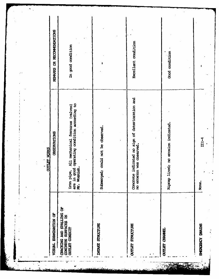
The weir structure and outlet pipe showed no signs of deterioration
and were functioning properly at the time of inspection, (Photos No. 3
and 4, Appendix II). The 36 inch outlet facility was reportedly in
good operating condition a0oxxifig t Mr- . Wozniak. The plunge pool
riprap was intact indicating no signs of movement or erosion.
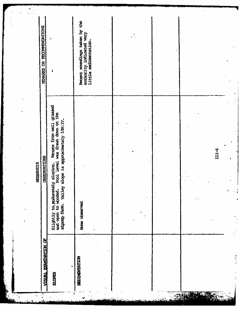
3.1.3 Reservoir Area: The reservoir area was free of debris and
the perimeter was grassed except for the upper reaches. The reservoir
is located in a valley with side slopes at approximately l0H:lV,
(see Overview Potos, Page 3). No sediment buildup was observed.
A staff gage does not exist for this structure.
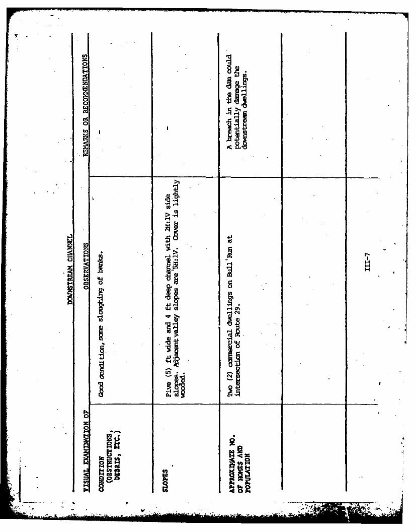
3.1.4 Downstream Area: The downstream channel consists of a 5
ft wide channel located in a valley with side slopes of 5H:IV. ibis
valley is lightly wooded. Appoxcimately two miles downstream at the
intersection of Bull Rm and Route 29 there are w coummercial
facilities at stream bank level.
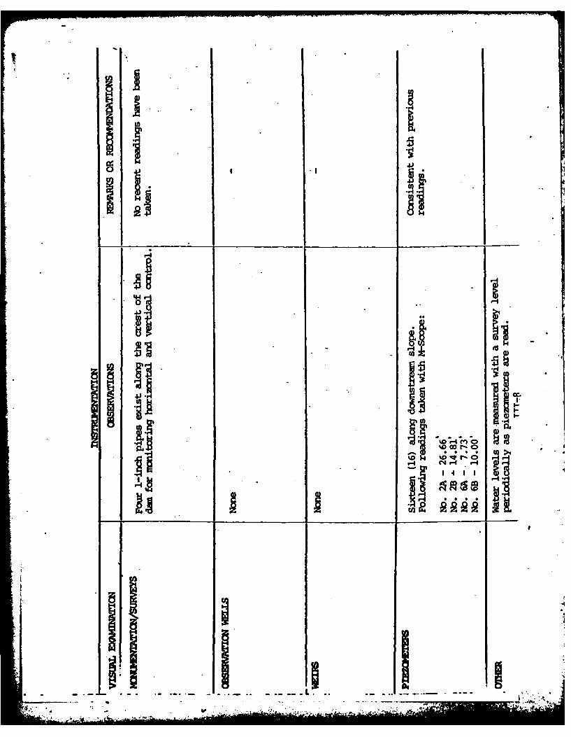
3.1.5 Instrumentation: Pour (4) 1-inch diameter iron pipe
Szmnuents exist on the crest of the dam, which are used for horizontal
and vertical control. Their locations are provided on Sheet 15 of
Appemdix IV. Sixteen (16) piezceters have been installed along the
downstream slope. Previous readings and locatios are included in
Appoiix V.

3.2 Evaluation: Overall, the d= was in good oondition at
the time of the inspection. The vegetative cover appears to be
j well maintained and no trees were growing on the eubarftnt. A
routine ,aintenane program exists for this structure. Riprap
present along the upstream slope, in the plunge pool, and along.
the downstream outlet channel is in good condition and appears
to be functioning properly. NM surface erosion was observed on
the embankment or in the abutment areas. The internal drainage
system is apparently functioning properly, as no seepage was ob-
served along the downstream toe and piezometer readings taken during
the inspection are consistent with previous readings.
The outlet pipe and principal spillway are in good structural
cmdition. All operating appurtenances are functionally good. A
staff gage should be installed to usually nirntor pool levels. Water
levels are monitored when piezcmeter readings are made using a surveyor's
level.
3.2.2 Downstrem Area: A breach in the Upper OCx:oquan egional
Water Reclaation Plant Dau during extrme flooding conditions could
potentially damage the downstream dwellings.
t
-13-
SKCTIN 4 - OPEPATICNAL PR)C3RES
4.1 Procedures: Upper Occoquan Regional Water Reclamation
Plant Dan is used for dilution of wastewater discharges. The
normal pool elevation (18749 msl) is maintained by a weir acting as the
principal spillway. Water autnmatically flows over the low weir when
pool levels exceed elevation 187.5 ml, and over the entire weir when
pool levels exceed elevation 188 msl. An intake structure with inlets
at various elevations below normal pool is used to decant water from the
reservoir at different levels within the reservoir. The water quality
at the various levels dictate at which level water iS decanted.
4.2 Maintenance of Dan and Appurtenances: Maintenance is the
responsibility of the Owner. Maintenance consists of inspection,
debris removal, mowing of vegetative cover, and repair.
4.3 Warning System The emrgency action plan does not include a
downstremn warning systu or evacuation plan for the dam. (See Apperndix IV.p.3
4.4 Evaluation: The dam and appurtenances are in good
operating condition. Maintenance of the dam is good. Records should
be maintained of all maintenanoe and operational procedures for future
reference. An emergency action and warning plan for the downstream
ezsashould be developed. It is recnmerded that a formal emergency pro-
.cefebe prepared and furnished to all operating personnel. This should
:'-include: .
a. How to operate the dam during an emergency.
b. Nho to notify, including public officials, in case evacuation
frm the dmnstreu area is necessary.
-14-

SBCrQN 5 - irYAWcs/MFLoGIc MA
5.1 Design: The dam was designed by CH2M-HiU as a multi-purpose
dam and a portion of the hydrologic and hydraulic data is available. Data
used included the stage-discharge and stage-storage area curves made
available.
5.2 HLdrologic Records: There are no records available.
5.3 Flood Eqperience: Is not known.
5.4 Flood Potentials: In accordance with the established
guidelines, the Spillway Design Flood is based on the estimated
"Probable ?Mximu Flood" for the region (flood discharges that
may be expected from the most severe combination of critical
meteorologic and hydrologic conditions that are reasonably
possible in the region), or fractions thereof. The Probable
MaxJ== Flood (PH), hydrograph was developed by the SCS method
(Reference 5, Apendix VI). Precipitation amounts for the flood
hydrograph of the PME are taken fran the U. S. Weather Bureau
Information (Refernce 6, Appendix VI). Appropriate adjustmets
for basin size aid shape were accounted for. These hydrographs were
routed through the reservoir to determine maximum pool elevations.
5.5 Reservoir Regulation: Fbr routing purposes, the pool
at the beginning of flood was assumed to be at elevation 188 msl.
Reservoir stage-storage data and stage-discharge data were de-
termined from the design report and plans. Floods were routed
through the reservoir using the principal spillway discharge.
The 36 inch outlet pipe was asswtaI to be closed.
-15-
.*** *,<-
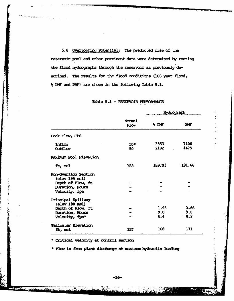
5.6 Overtoping Potential: The predicted rise of the
reservoir pool and other pertinent data were determined by routing
the flood hydrographs through the reservoir as previously de-
scribed. The results for the flood conditions (100 year flood,
PW and OW) are shown in the following Table 5.1.
Table 5.1 - RESEMIR PENf)IACE
Hydrograph
NormalFlow PW PWF
Peak Flow, CFS
Inflow 50* 3553 7106Outflow 50 2192 4475
Maxinm Pool Elevation
ft, msl 188 109.93 : 91.66
Non-Overflow Section(elev 195 =sI)Depth of Flow, ft - -Duration, nurs - -
Velocity, fps - -
Principal Spllway(elev 188 msl)SDepth of Flow, ft 1 .93 3.66
Duration, Hours .9.0 9.0Velocity, fps* 6.4 8.2
Tailwater Elevationft, sl 157 168 171
* Critical velocity at ontrol section
* F1w is ftm plant dischre at mximum hydraulic loading
4' -16-

5.7 Reservoir Eptyinyg Potential: A 36-inch diameter outlet
at invert elevation 161 msl is capable of draining the reservoir to
elevation 161 msl. Assuming that the lake is at normal pool elevation
(188 msl) and there is 50 cfs inflow, it would take approximately
two days (13.5 ft per day) to lower the reservoir to elevation 161 msl.
5.8 Evaluation: The U. S. Army, Corps of Engineers, guidelines
indicate the appropriate Spillway Design Flood (SDF) for an inter-
mediate size, significant hazard dam is the h PMF to PMF. Because
of the risk involved, the h PM has been selected as the SDF. The
spillway will pass in excess of 100 percent of the PMF (200 percent
of the SDF).
Hydrologic data used in the evaluation pertains to present day
conditions with no consideration given to future development.
-17-
SEION 6 - DAM STABILITY
6.1 Foundation and Abutments: The dam is located in the
Piedment physiographic province of Virginia. Red micaceous shale
with thin sandstone interbeds are exposed along the right side of
the spillway outlet channel. These rocks belong to the Newark
Formation of Triassic Age. The dam and reservoir are underlain by
similar rocks and it is likely that diabase dikes traverse the site
intermittently. Available geologic maps of the area do not hidicate
the presence of any faults in the site vicinity.
Test boring and test pit data (Plate No. 8, Appendix I) indicate
the embankment and abutments are underlain basically by a thin veneer
of residual soils (probably S4 to ML materials) resting upon de-
cumposed to slightly weathered shale and "siltstone". Although no
field permeability data was provided, natural permeabilities in
Triassic shales are typically low except in the presence of fracturing
or jointing, which result in higher natural pexmeabilities. Jointing
was noted on the exposed rock on the right side of the discharge channel.
Based upon the materials encountered in the test pits and test
borings, a stable foundation is assumed. Gradual consolidation
of the underlying soils would be expected during application of
fill materials. The underlying soils probably has essentially
fully consolidated under the applied load not long after completion
of ocnstrution. A 1. ft canter was recummended in design, however
no readings on the monuments were available for comparing the actual
amout of settleent.
-18- L ,
' - .. - .. : .. ... _. _
6.2 Embankment:
6.2.1 Materials: Design drawings show the dam as a zoned
structure. The "impervious core" and cutoff were constructed with
mixtures of clayey silt, silt and decomposed shale up to 2 inches
in maximum size. The outer shell or "randon embankment" was con-
structed with more penreable mixtures of clayey silt, silt, decaposed
shale and shale up to 6 inches in naxwhun size. Materials in both
zones were to be compacted to a "minimun of 98 percent relative
cmpaction" as defined in the construction specifications. Lift
thicknesses were not to exceed 6 inches in cupacted thickness.
6.2.2 Subdrains and Seepage: In attempt to control seepage
beneath the embankment, a cutoff was constructed into the decomposed
shale as shown on Plate No. 3, Appendix I. An internal drainage
system for collecting seepage and controlling the phreatic surface
through the embankment was also provided. This system consists of
12 to 25 ft wide strip drain conposed of graded sand and gravel
located beneath the downstream slope, directly below the "inpervious
core". Thirteen (13) relief wells extend beneath the strip drain to
reduce uplift pressures. Drainage pipes were provided for transmdtting
the ollected water to an outlet channel. Design details ere given
on Plates No. 3 and 4 of Appendix I. In atteapt to prevent piping
around the 36 inch outlet pipe, five (5) anti-seep collars were
included as shown on Plate No. 6, Appendix I. Sixteen (16) piezcteters
uvre installed to nwitor the phreatic surface through the embanwmt.
- - ---9-
-" ,,,..',.• -- - t . '
6.2.3 Stability: A stability analysis was reportedly performed
for this structure, but this information was not provided. The dam
is 41 ft high and has a crest width of 20 ft. A graveled access road
traverses the crest of the dam. The upstream slope is 4H:lV and in-
cludes riprap from elevation 183 mnsl to the crest of the dam (elevation
195 mns1). The downstream slope is 4H:IV. The dam is subjected to
sudden drawdown because the approximate reservoir drawdown rate of
13.5 ft per day exceeds the critical rate of 0.5 ft per day for
earth dams. The existing pool during the inspection was approximately
5.5 ft below maximum control storage pool which is at the crest of the
principal spillway weir. The dam normally experiences the maximun
control storage pool with no apparent side effects.
Although design drawings show the dam as a zoned structure, both
the "inpervious core" and "randam embankment" were constructed with
essentially the same materials, (see Section 6.2.1). Therefore, the
embankment stability is assessed assuming a homogeneous dam. Accxrding
to the guidelines presented in Design of Small Dams, U. S. Deparbment
of the Interior, Bureau of Reclamation for small homogeneous dams,
with stable foundation, subjected to a drawdom and composed of SM to
ML materials, the recommended slopes are 3H:IV to 3.SH:IV upstream
and 2H:lV to 2.5H:1V downstream. The recumended width is 18.2 ft.
Based on these general guidelines, the embankment slopes and crest width
are adequate.6.2.4 Seismic Stability: The dam is located in Seismic Zone 2.
Therefore, according to the Recomawr ed Guidelines for Safety Inspection
of Ds, the dam is considered to have no hazard from earthquakes pro-
-20-
- . AIA

vided static stability conditions are satisfactory and conventional
safety margins exist.
6.3 Evaluation: Based upon the visual inspection and the design
drawings, the foundation is considered stable. According to general
Bureau of Reclamation guidelines, the embankment slopes and crest
width are adequate. Piezcmeter readings indicate that the internal
drainage systen is functioning properly. Overtopping of the dam is
not a problem, as the spillway will pass 100 percent of the PME
(200 percent of the SDF). Since no undue settlement, cracking or
sloughing was noted at the time of inspection, it appears that the
embankment is adequate for maxinum control storage with water at
elevation 188 msl.
-21-

SCTO 7 - ASS M/RMEDIAL MEASU S
7.1 Dam Assessmnt: The available engineering data is adequate.
The visual inspection revealed the dam is in good condition and there
is no immediate need for remedial measures. There is a regular
maintenance operations program anx maintenance is good. There is
an emergency action plan but no warning plan for the downstream area.
OCrps of Engineers guidelines indicate the appropriate Spillway Design
Flood (SDF) for a smal size and significant hazard dam is the PMF. The
spillway will pass in excess of 100 percent of the PMF (200 percent of the
SIP). The spillway is judged adequate asit wll pass the SDP without over-
topping the dam. A stability check of the dam is rot required as
the embankment slopes and crest meet Bureau of Reclamation guidelines.
7.2 Recniend Remedial Measures: The following remedial
measures are reormarded:
a) A warning system should be developed for the downstrem area.
b) A staff gage should be installed to visually monitor water
levels.
-22-
, . .. . . .. ., . * ' .' :

APPENDIX IHPS AND DPAWING
FAIANAS A'sa 0
i- INAG
a . 4i lIe C
L E~j UPPE ~O 01t,"A WGAUNR
-- C
INAGE ~ hrI . 38WW7227
;v . -3:K
1,e I
* ' d * c7
I.. . ~ . 16
\PAA* * *
* i. w U ~ -~r r' '~ ~ . N Az
,~~~~~
des~'v~~--
SL . 4 . 'r

. ~ * . . cAea- 10**kvl -- L.me WftIa 1
-. W .awCA "*NvO
16A. eOW.L TO
a...; t.. co%1T
C. % W,
~IW PIV, ~. .*ilp
- sr. __ i
A'WAW"- *
-46
Ji'
N.. .d - ..
Nr
vort * -
__01 IDRA M
.Ate
WX -*I
y~q 9
VI S*f wb
a l**. . .*
4- U M *W 1 O
Tov O shba
4'I~WU il\
*~ ~ ~ I "%MU~POIL
ecmr\ .
sMwNM* I*CAIA
.. . ~ .. ...
ef~ IL *a,*.
'm~~ ~ ~ s-e" "O- 10 Tc dkwdmwam~ox
_% M AinPPOSIM L~
ta _ * am.
tam AIV ~u U ~tm
- &M WA .M op .m to M O n ."o
a- IPofompi* of, 9
;?BrA6* 2W AQ
*.ImJ AA
5 , ... ... .. T IF
A.1.1 - a
ae a
, _________ 5"'l
IVA I lp .
- hC~ WESY'
OW Mm4tva [email protected]~~dhVCa~AWI"WNW0 m AAAA vu*1 ~
Is T0 ~ ~ ~ ~ ~ ~ ~ ~ ~ ~ EEA PLA s v--. 1S *tSmq*a.gGcY
'a r-
~~1 * a. a
14
ST V-cK . R- g-~
i
*@-o a - T-
t3 ''XA?% ON - - Iw _
lp
2y0000
AM L. &6ffV.%T'n
f (D
~PAT .. 'I __
.'. 'NW
,j"m memo% /IL *at
DAM ST
NEA PLA

*iob Il #A__ __ __ __* ,~@00,
S. - . .
* .. a&m % Ant*
-~ - - .~~if-Go3
.2o*80S~w -- 00 . ic . a *N%.N ow I'oaI-.
"t .Aeso'i %w / t 4
all \..* * .. IW " o bo V-9 .
U4. VMM S 4 .;.:-6___
.8 who o4 _____
jam . .* .
t C6
witi
CREST OF&TAIL.
t'* .4 UM~ _
T- afa ZCaw"~
1-&S% Ak
IST. OO'N *Vm
Ww£
-. ~CW 4 - -
p*Y~q~971L
'~lowlie. ~ ~ II . p
name*~tg~ -a Il
6ie *Uh. '~%44 ~"'" ~ r riever-,"I
"4 ~ w E5AT ORAWN
ov me
.-
-,OAM OE.AILswap~6 a L 4rSs
... te:

se 0. I& post WL*- co *&#A
. .. ...... -----
7' -I= - PC*=
77 - -
\. -
~IMP or . .
pip..i
. *7..
.5t i.-,--77. *,. 'I 7t

ILA
... ... - - - - - - - -- -- --
..............
.344
sit j I i
- ~ ' ivmmg tow- 7-
Si It*C Wa11~l6 - k4 f~IN.....
t-,Rgco~. DR LA
13 t 'Rom MM
WEMA PLC ___ _____ __ONO
4.4~~Mkiw A ROR'DAW 4G~

.. 411
PAML Cuw.mO 4%
M p4AIRTR 1' 9*16 Vvt riS
- - -*1- * - _ - 4*3bf~ O7*~ p ~ -~-~-~ -@ -T . v - 4
'4.i r .UAhS~
ba~ r %4k *Ma dx.O4CLA i~aLCG-OW N!]L.oo sm.. 6*5
w. PE SEA t
.9 -1- ~ 15 vp Y %.,& el
.9.... Ii* - ~ @i*~4* 9 W *9
0==..- .4. -.. -- 0K Uasg..m. OL~& cooml
. OU1*L.B1' 'VOC~tK PI..AN
,9. rv tj*9
~c 1 .~-A

0-W 00. .
PC-.J I2aod scam cbLL
S .4h~L J?
*= lm . - ..
*~~~* V4 a..~~K T
51LI~tIO L C0a R
4*. 4 r w rm . "to flclaf' -wf Trim.
OULT OK
LAN, PRFL EAL
£~~~ *mass a .a.~
IWWI' F
* S'CI.
ALM~. bj 0i~
Root l* If
Ai
7~~~~ .-=a W '
-- * r
- aso-me
4W 1.4j'&.hatW&~qo saw.
AW*E,. CIA
. I -. 4,
log I
I _________own
___ ~~,Jt. 1 L *

1- cc :1 ,c
J% LA -a -. ,-1.
V, -4 :
s ki. -V g% c v o T.1* 06M I' Lws tbOt
- Tarj
II Akm sw i M .-FAMW
. f1~ -i
IOUTLET UV.
1MN TMTRfr.~-W~bac
t-f J,.I. 4

.~~%_____ - '5 t T;c~4..~~. - L.1..
I IFML
CU-
____
Iita-
7-- -A-
-- - 'W
41 JIM-
4.40-
-- -l'if
- 2
m Boo CLM NXo
___. SAVIY N. 'OM &. W A. M*?4 am0~VAfOPam GUIAW*OA
S." of% low I OI too'r" N*040 MO UWA IftAJ.WI~ tUv %4P
INS $IM 0%u .%AAL~ 011$ MS OPW01 A 4 4 -%6# 444f W )?
ImN SN fw W t O M dtw i.f**s~utf ir~ .Awot dw
easmem *"*tTlIWW I ftm S
=r.. Sp a OW" Wff*E'l p '%a e m e w . ;g ? S A I t~ S h 0 I~I
- 4L U ~ £ u
RIK=D DRAWING -- ~ .MM41
I
I.
N
APP~DIX I~
~OG1~APHS.
I~~1~~' . 5,
V....................... I*.****.-. , .1-

4J-
Pho~to No. 11XO*NSTREM CHANL
Pho~to No. 2DrOgNSTrEM SLOPE OF DAM

Photo No 3SPILLW~AY (WOCING UiP STREAM)
Photo Nok. 4DISCHARGE CHANNEL FDR SPILLWAY
11-2
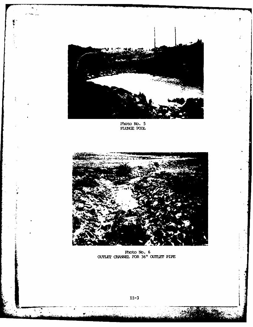
Photo No. 5PLUNGE POO)L
Photo No. 6OIJEIE CHA~NNEL FOR 36" WfLMET PIPE
11-3
It"A

APPEM~IX IIIFI~Xr OBSERVATINS
*1 iP24
I HP
'4
0%0
a49
,I "I illi
Us
0-
U' wI
43aq
3~i~i~ jy.r z)
En2* I'l4349~
1849

z 4
Cd H
W 44J
tV0)t. : .
49 41
J ~0 14
KaI-4 4.
49((
0 0
44
§.~ ~4 -* . -*. -
-44
g . .

U2fz
'41
0ii
1 0
ii tA
I iiiAd r-
ido
hli
InI
IIo ho+.I
0
01>1
-- + . ++ . .. .. . . .. . .
tt
II
.I..
i i.,. . . . . .. . . ... .. . . .. .. . . . . .. .. imAI 11 1ONE'
APPENDIX IVOPERATIONS SUVfAM
Ma kf1

EFFLUENT RESERVOIR
PURPOSE AND INTENT
The reservoir is meant to serve three primary purposes:
1. It provides an aquatic ecological system to achieve
the supplemental nitrogen removal demonstrated at
the South Lake Tahoe effluent reservoir.
2. It acts as a detention pond for the treatment
plant effluent offering the ability to greatlydilute the effects of a temporary deterioration ia
plant effluent quality. (A dilution factor of
1,000 for 24 minutes of plant effluent flow at
10.9 mgd.)
3. It serves as a water recreational area offering
fishing, boating, swimming, and other water contact
sports.
DESIGN CRITERIA
Reservoir Area 56 acres
Reservoir Storage Volume 180 million gallons(552 acre-feet)
Normal Water Surface Variation 0.50 ft
Normal Discharge (ultimate plant
development) 50 cfs
-J U
IV-1
• 'b

093211 - 2
Spillway Discharge:
100-year design storm 775 cfs
Design flood 3,350 cfs /
Design capacity 3,500 cfs -
DESCRIPTION
The treated plant effluent discharges into the effluent
reservoir, overflows into Bull Run Creek, and finally flows
into the Occoquan Reservoir--preserving a badly needed water
reso'irce in the Occoquan Basin.
The effluent dam and reservoir is located in northeast
Virginia 25 miles west of Washington, D.C., and 15 miles
south of Dulles International Airport. The contributing
watershed to the dam has an area of 0.89 square miles and
is, for the most part, undeveloped at this time. The eleva-
tion of the watershed rises from an elevation of 160 feet
above sea level at the dam to a maximum of 340 feet. The
watershed consists of rolling hills with a maximum watercourse
of one mile which gives a runoff time (time of concentration)
of approximately 30 to 45 minutes.
The effluent reservoir has an area of 56 acres and a storage
volume of 180 million gallons (552 acre-feet). Ultimately,
the plant will have a continuous discharge to the effluent
reservoir of 50 cfs. The reservoir spillway is designed for
a maximum discharge of 3,500 cfs. A multiple valved intake
structure is provided to allow drawoff at various levels.
(Refer to Figure VI-Gi.) The ability to draw off water at
various levels in the reservoir during the summer months
when the reservoir is stratified is desirable for controlling
algae buildup or other unfavorable conditions.
IV-2
• . . .i :i; - i ....... .
992364 -3
Table VI-Gi presents a summary of the reservoir cross sectionE.
Figure VI-G2 shows the location of these cross sections.
EMERGENCY OPERATIONS AND FAILURE FEATURES
Prior to discharging into the effluent reservoir, the treated
plant effluent passes through the effluent automatic stop
gate. This gate closes when the plant effluent fails to
meet the monitored discharge standards. A mechanical or
electrical failure of this valve is extremely critical.
(Refer to the Failure Modes and Effects Analysis, page A-33.)
If the stop gate fails to operate properly under automatic
control, the "OPEN" and "CLOSE" pushbuttons may be manually
operated at the gate. If these pushbuttons fail to operate
the gate, the gate can be operated by turning the manual
handwheel operator.C .
During the period when the gate fails to operate in the
automatic mode, it will be necessary to manually close the
gate at any time the computer signals the effluent quality
is below standard. The gate will also have to be manually
opened when the effluent quality again becomes acceptable.
OPERATION PROCEDURES
STARTUP
Upon completion of the effluent dam construction, a 36-inch
blind flange is used to close off the open tee of the intake
structure. The three valves at the intake structure are
closed. To keep the 36-inch line empty when the outlet system
is not in use, the 36-inch butterfly valve at the terminal
IV-3
liV U
149707 - 4
structure should be left open. The water then accumualates
in the reservoir until the water surface reaches Elevation
187.5, starts to flow over the weir structure, and flows
through the 24-inch spillway pipe to the stilling basin.
The reservoir is now in normal operation.
ROUTINE OPERATION
The reservoir water surface will vary from a normal elevation
of 188.0 to the maximum probable storm elevation of 190.6 as
it discharges from 50 cfs to 3,500 cfs over the spillway.
SHUTDOWN
If it is necessary to drain the reservoir for inspection or
maintenance, the 36-inch hydraulic gate valve at the intake
structure is opened. The 36-inch butterfly valve in the
terminal structure is then gradually opened to drain the
reservoir at the desired rate. The rate of release should
be slow to prevent a sudden drawdown condition from developing
in the dam embankment. Generally, releases should be
controlled so the drop in water surface is limited to I footper day.
EMERGENCY
In the case of an emergency when the rapid draining is
necessary, all the upstream gate valves and the downstream
butterfly should be fully opened.
ABNORMAL OPERATION
Thermal, nutrient, or dissolved oxygen stratification in" the
effluent reservoir could cause undesirable algae growth or
IV-4
r 121563 - 5
other unfavorable conditions. Algae can be removed front the
*lower depths of the reservoir to prevent a long-term buildup
of nutrients by drawing water out of the reservoir at one of
two different levels below the surface. An 8-inch hydraulic
gate valve is provided at the intake structure at Elevation 177.5
and a 10-inch hydraulic gate valve at Elevation 166.5. When
drawing off water through one of these gate valves, the
36-inch butterfly valve at the terminal structure must be
throttled to control the discharge rate.
OUTLET SYSTEM
Normally, the reservoir will be full with the water level
controlled by the spillway crest. If it is necessary to
release flow through the outlet works, the order in which
the valves are opened and closed can affect the operation of
the system. The following are suggested steps for the least
effort and wear on the system:
1. The 36-inch pipe should be empty when the system
is not being used. The downstream butterfly valve
should be left open.
2. To release water, open the upstream valve or
valves.
The 36-inch gate valve could require pressures
above 1,000 psi to start its motion due to the
friction buildup and the differential pressure.
If the 36-inch valve lines approach maximum operating
pressure of 2,000 psi, check the steps outlined in
the section "Hydraulic System." If operating
methods are correct and valve is still difficult
to open, attempts should be made to equalize the
pressure on both sides of the 36-inch valve. To
IV-5

re ( o e, - S-in-. -)r
..Th or bth upsztr. a - " a.d (c) wi.n
outlet pipe is full .',ubbles and boi:-
stcp -t the v-lve . :) , (> l2 the 36-jn- ±:, :e
valve. T, n , r. t eam butterfly valve can ',cn
ope.r'd 'cc.. t the flow of water.
3. To stop 2,c.w of %dter through the pipe ' se e
ups: .c:m valve. In case of malfunction
"T :cicam valves or when a ouick shutoff is ,
-iy. the downstream butterfly valv, ;j be d
to stop flo- through the outlet system.
HVD AJLIC VALVE OPERATING SYSTEM
'iqtwre VI-G3 shows a sketch c.- the hy'rai ic valvc operati.!,7
S ei±ri. T9 oper -r -io ,i~y of sr n -ate vwlxes
the follcAing - *re suggested:
1. Check oil level in reservoir.
2. After the pump handle has .. :; rotated "pnI.',
pull up on the lever to tho iqht of haiojae 4o
close the - k valve. If tle chc-c" v 1*-:j
not c-osc pressure cannot build wp in ti:
system.
3. Plece poi7:-,r on 1ert .=ide of p ,, ,to either"open' or "close" itn.
4. All the -- .ies a,-,: ... - d hy ciamat-r sire
on the co; 2 panel. . C,
are two (2) 7:-)d .,eector , s.;
IV-6
Lit

111793 - 7
other for each of the three gate valves. For which-
ever valve chosen, open both hand selector valves
by turning counterclockwise both hand selector
valves to the fully open position. If both sides
are not opened, the fluid cannot return and the
piston on the gate valve will not move in either
direction. Pressure will continue to rise if both
hand selector valves are not opened.
5. Start pumping using the pump handle.
The position of the gate valves is difficult to
determine. It can be approximated by counting
strokes or timing the duration of the pumping and
observing changes in the pressure gauge.
6. The pressure in the system rises abruptly when
(- valve is fully opened or closed. Once the valve
is opened or closed, do not continue to pump.
To fully open or close the 36-inch valve, approx-
imately 15 minutes of constant pumping is necessary.
The smaller valves are opened in 5 to 6 minutes.
To unseat the 36-inch valve, more than 1,000 psi
(maximum allowable pressure 2,000 psi) may be
necessary. Once the seal is broken, the operating
pressure should be less than 1,000 psi.
After the valve is "opened" or "closed":
1. Close both hand selector valves completely by
turning the valves clockwise.
2. Push the check valve lever down to release the
pressure built up in the system.
IV-Alf

111792 - B
It is important to periodically exercise the system by
operating all the valves. At least once a year is suggested.
INSPECTION PROCEDURES
The dam embankments, strip drain system, abutments, spillway
chute, retaining wall and stilling basin, spillway underdrain
system, and piezometers should be checked in detail on a
bimonthly basis until the reservoir level reaches normal
pool elevation and piezometer levels have stabilized.
During this period, settlement measurements should be taken
on a monthly basis unless results indicate more frequent
checks are needed.
After conditions have stabilized, inspections and piezometer
measurements should be made on at least a monthly basis.
Records should be kept and the data reported to and reviewed
by qualified personnel.
EMBANKMENT
The crest and downstream slopes of the embankments should be
inspected for visual evidence of settlement, slides, cracks,
bulging, or other signs of movement or erosion. When the
reservoir is drawn down, the upstream slopes should be
checked also. The settlement monuments should be checked
for changes in alignment and elevation monthly until the
reservoir is filled and the piezometers stabilized, and
annually thereafter.
Careful inspections should be made of both the upstream and
downstream slopes of the main embankment and the short dam
for evidence of rodent mounding, tunneling or borings.
--- IV-8

362844 - 9
Any activity of rodents on the embankments should be
eliminated and damage corrected.
ABUTMENTS
The abutments should be inspected for any erosion and visual
evidence of movement, slides, or cracks.
SPRINGS OR WET SPOTS
Examination of the embankment and abutments and downstream
valley should be made for seepage or springs or unusual
growth of grass and vegetation. All springs and seeps
should be located and recorded on the plan of the dam and
flow measurements recorded. Construct weirs to measure
flow when necessary. The results should be reviewed for
changes in the flow. Sample and test seepage water for
soil particles (which may indicate internal erosion or piping
from the dam or abutments).
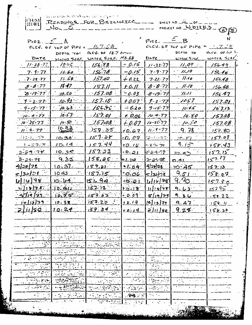
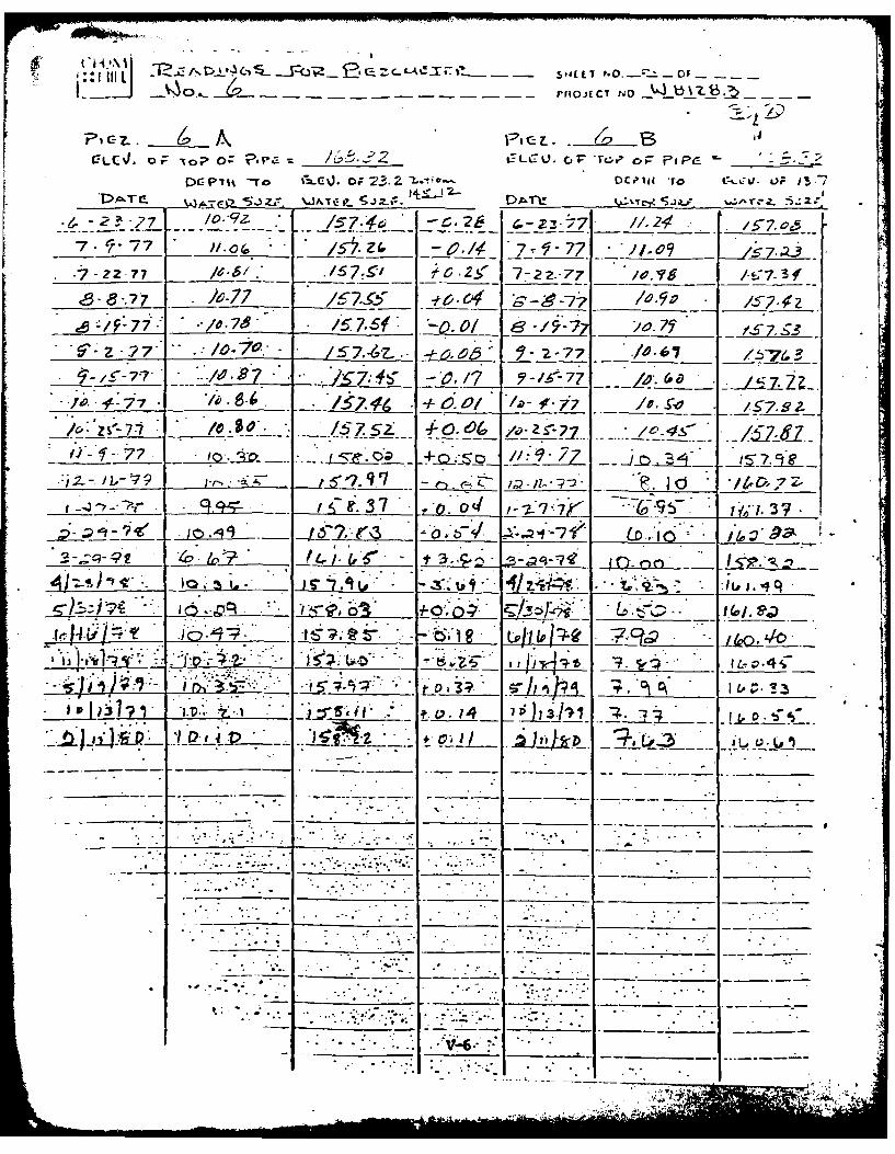
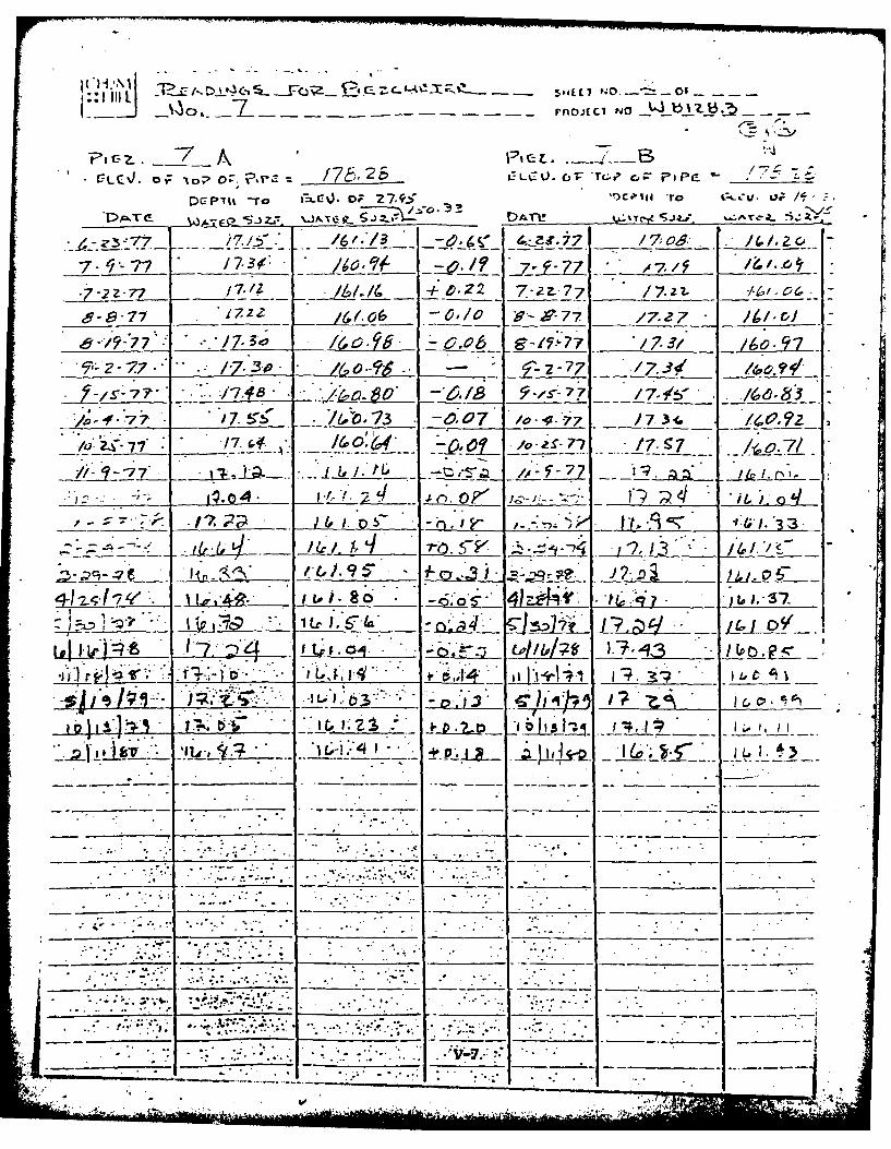
PIEZOMETERS
The piezometers should be read with the electric well depth
gauge provided. A rag tape with a weight could be used but
will not be as dependable. The piezometers should be read
any time the reservoir rises suddenly above the spillway
crest and if the reservoir is emptied. Check the hole in
the cap to be sure the piezometer is vented to the atmos-
phere. See Figure VI-G4 for a location and numbering of
the piezometers.
SETTLEMENT MONUMENTS
Accurate surveying techniques should be used to monitor the
settlement monuments. A check on the elevator bench mark
IV-9
362844 - 9
Any activity of rodents on the embankments should be
eliminated and damage corrected.
ABUTMENTS
The abutments should be inspected for any erosion and visual
evidence of movement, slides, or cracks.
SPRINGS OR WET SPOTS
Examination of the embankment and abutments and downstream
valley should be made for seepage or springs or unusual
growth of grass and vegetation. All springs and seeps
should be located and recorded on the plan of the dam and
flow measurements recorded. Construct weirs to measure
flow when necessary. The results should be reviewed for
changes in the flow. Sample and test seepage water for
soil particles (which may indicate internal erosion or piping
from the dam or abutments).
PIEZOMETERS
The piezometers should be read with the electric well depth
gauge provided. A rag tape with a weight could be used but
will not be as dependable. The piezometers should be read
any time the reservoir rises suddenly above the spillway
crest and if the reservoir is emptied. Check the hole in
the cap to be sure the piezometer is vented to the atmos-
phere. See Figure VI-G4 for a location and numbering of
the piezometers.
SETTLEMENT MONUMENTS
Accurate surveying techniques should be used to monitor the
settlement monuments. A check on the elevator bench mark
IV-9
362846 - 10
should be made each time to ensure that no settlement has
taken place. See Figure VI-G5 for the monument locations
and elevations.
STRIP DRAIN
Examination of the exit drain pipe should be made. The
amount of flow should be recorded. Sample the flow and test
for any soil particles (which may indicate internal erosion
or piping).
SPILLWAY
The general condition of the spillway entrance slopes, weir
wall chute, underdrain system and stilling basin should be
made after each heavy flow. The log boom should be checked
to ensure the cables are positioned properly. The water
level in the underdrain manholes should be noted and signs
of clogging or flooding reported. The concrete walls,
slabs, and weirs should be inspected for any cracks, seepage,
or movement at construction joints. Inspect the downstream
channel and riprap for erosion.
OUTLET
Inspect the submerged portions of the outlet structures, the
valves, and hydraulic system each time the reservoir is
drained. Inspect the outlet pipe by crawling through it and
the terminal structure once a year. Condition of the trash-
racks and the tubing under water should be noted. Regular
checks of the air vent should be made to make sure it is not
plugged. When the outlet is discharging, there should
be an audible sucking of air at the vent opening. Each
valve should be checked individually for leakage or mal-
functioning and any difficulty in opening of the valves noted.
IV-10

872323 - 11
The hydraulic control box should be checked for any vandalism.
The flexible hoses should be checked for any spots showing
wear or leaks. The terminal structure should be checked for
any cracks., especially around the 36-inch pipe where it
enters the terminal structure for evidence of seepage along
the encased pipe. Any seepage inside the structure or along
the outside should be noted.
RESERVOIR
When the reservoir is drawn down, examination of the plant
discharge pipe should be made for any undermining or removal
of the pipe base. Periodically, measurements of the reservoir
silting can be made using the cross-sections shown in the
appendix. Inspect the shoreline for (1) evidence of landslides,
(2) erosion at creeks, (3) erosion by waves.I
PHOTOGRAPHS
Each year a series of photographs should be taken. These
photos should show details as well as overall views. Return
to the same spot each year to take the photos.
MAINTENANCE PROCEDURES
FLOATING DEBRIS
Floating debris collected by log booms should be floated to
shallow areas where it can be removed. Debris accumulating
at the stilling basin exit may cause damage to the fence and
flood gate and should be removed. Every attempt should be
*made to prevent large debris from entering the spillway where
it could become lodged and prevent efficient discharge over
the weirs or cause damage to spillway chute and stilling
I I -
* r ra

BE26 - 12
basin. When the reservoir is lowered, any debris around the
intake box should also be disposed of.
EROSION CONTROL
The construction areas stripped of plant growth have been
seeded with grass to reduce erosion. It may be necessary to
reseed several areas. Drainage on the crest of the dam
should be checked, and periodic grading should be done to
prevent water from ponding in the road. Ditching, drains,
and repairs to eroded areas should be made to protect the dam
and abutments. The upstream slope of the short dam is not
protected with riprap. It is possible that some erosion
of this surface will occur with time, and maintenance may
be required. The spillway and outlet channel may require
maintenance and additional riprap.
CLEARING
Brush and trees which start to grow on the downstream face
of the dam and abutments should be cut. Vegetation should be
removed from the channel in front of the exit drain pipe
so that flow from the pipes can be observed.
SPILLWAY
Any damage to the log boom, weir walls or stilling basin
caused by floating debris should be repaired. Repair erosion
of the concrete with epoxy or other materials required.
RESERVOIR SILTING
Silt carried by the tributary creeks will settle in the
reservoir. Filling the reservoir as previously indicated will
limit the amount of silt which settles around the intake
IV-12
- . -
structure. However, silt will eventually collect around the
inlet, and it may be necessary to remove this material some
time in the future.
OUTLET SYSTEM
Periodic maintenance should be performed by operating the.
system using all the valves.
SEEPAGE CONTROL
If seepage or damp spots are observed on the slope of the
dam, abutments, or in the valley downstream, recommendations
for maintenance should be made by a qualified person with a
thorough knowledge of the dam design and construction.
Examples of maintenance steps may be the construction of
drains and filters and surface erosion protection. Also, if
( the uplift pressure measured by the piezometers is high,
then methods such as additional foundation drain wells may
be required.
GRASS MOWING
Complete mowing of the site should be scheduled bi-weekly
during the growing seasons. At all times the vegetation
should be mowed before its height exceeds 12 inches and
before weeds go to seed. The grass should not be cut to a
height less than 6 inches.
Any unusual growth patterns or color changes in the grass
should be reported. For proper applications of fertilizers
or other chemicals the local agricultural extension agent or
Soils Conservation Service agent should be consulted.
IV-13
: 777. _ " - i :.

VALVING SUMMARY
Mode of Operation Valving
Normal operation 1. All intake structure
valves are closed.
2. The 36-inch butterfly
valve at the terminal
structure is open.
Drawing off water at depths 1. Open the appropriate 8-
of 10.5 or 21.5 feet or 10-inch drawoff valve
at the intake structure.
2. The 36-inch butterfly
valve at the terminal
structure should be open.
Draining the reservoir 1. Open the 36-inch gate
valve at the intake
structure.
2. Control the flow with the
36-inch butterfly valve
at the terminal structure.
IV-14
I:7 11.,... . ... -------.- -r ;'.- 4,; '. ,

9, V
60 0wf 0
Go* '
4DV .00-000%
I"
APPENDIX VPIEZ~X4UOE FEADIGS
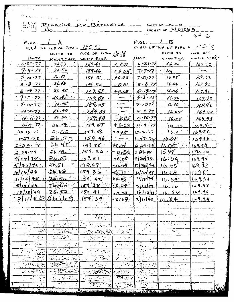
ZTh f2 C D-! £. Z~L t. -! --4L L1 eIO to) - 05 --.
__ g ~~j - - noflCI NO _UbtZWg
Dc-z, I I it~r -To /- J. oF I --. sDO14Cc -L)
I~c~Td~ ~ ~ ~ ~O~-Z 7 2aa
*7 777~ 7-'77 _ _
-7-Z2 -77 ___ 6? .5f 0 5 7-e2-77 DS__ _ ___ __ _
* 8-~-772~.4 5. 003 . - 67o__ _ _ __ 9.- _____ 8- - 7 __ __
S-/.Y-- 77 155 -.74.6m* J 77 .* _ _ _
'4 4~1J .. OL .04 /1Li 9,
3- __ __ ____ ___ - -7 -2_ _ _ _ _ _
____ ___ ____ ___ 15-q £ID - - 1 - -*f ~ L _ ___
__ ~ J5~j' ~ ~Q~m7A3l
* ~ ~ ~ J ___ __+
~~~i~J Uz- IL -*_14.~ ~zP
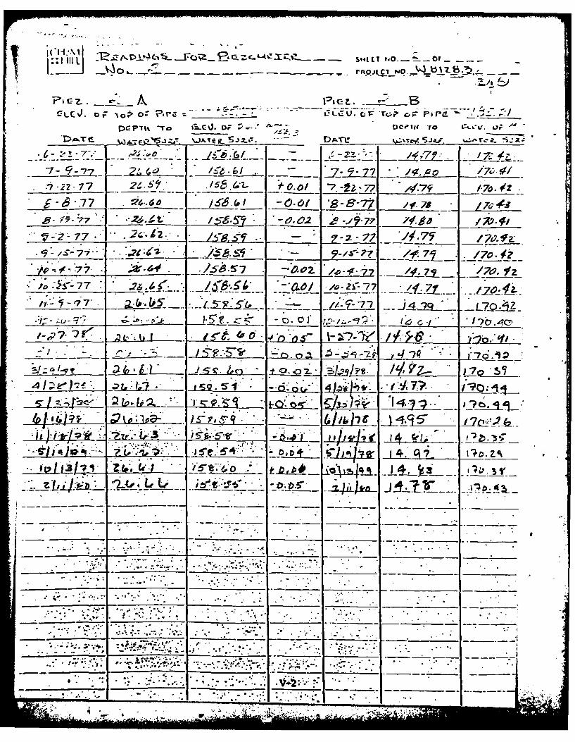
__' rnpojc NO.- b% -b
CLC-J. 0;7 0- ~o O '-r- J___ _ LCLt V. C,~ P~ c. jPpg -/..
Dc-plt -To i D~J F DCI# 0c'w ro -. 7 . 0;
-7 -J ' 9J -7- 6f
V9 99- 02 5__ 77 _ __ _ ______
-S- .7 /70.177, .it&# ___7_ _D-O2. 1A9,Z 2-i_ _ _ _
____ 7_ 7.O .2 o- 2Sr77 /.1 w.i
/1-7 ~ * /-7-7 J429 L7QA
2L -.-- S
-I-. -. 'i *-,;i ±o~--7v~-
(o L?. J1±ta~ s~L T 7o -.57_
-i .. 14 A I,,
I3 .
* .- S *.*.- - 7
-- 77
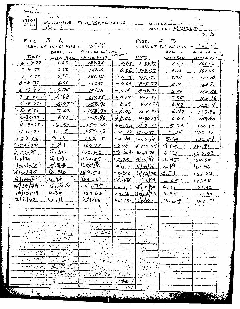
II L S-- - - - I NO. Z 0
-LEV. o 'VoP OC ?,--- C, rGL 'TL, C; -I PC.
DaP Ith -To t"= i. OF ff.I ''e DrI4 to , oe /, 2.
7- -7 .2 7T 7- -7 ,,.777 . a - z8 7- .7." ___4 "A
* *7.f-77. -_. - . .s. ( -O.Z 7.I. 7. __ .,_ _ =___, __.___~~7 Y._ 6.3 -- f57
.:i , ._"___ .". - ,. 11 gs/ _,._7 "., _. " " .. 3 -
- /-A. a 7 '-. 77 S.,_ _ .-. 38IS -7. 7_
- 7 , 40- - uo '7 S- 1-1 3- -.- _ :0 • t-I .'7
!',., -0 .-. 9 '- -7. 4 3__
. _____7 .__ ._-. ./3 . -,,. /-F_- 77.. _
l.: .k.;-. -. . ,:. S.."C, ._ /. -!7 4.-. .,,
' .-- .); '7S:.- /-:: . ; .- i-- .' /-;_3 ,g11 . 5 . _____,. __
* -c i 4 i/': * js• 0
S- 11)A ' A.4 __ __
* -* . -.. 4 . •.. .
* ,* ~ .- • .. .
1 . go
1. .. " w' 1 3 4,., .: . .-ۥ . .. , - . . . . -
"" " :" " " =::" :' "- '.. : 'T" '-• - .':" -"-'".:, - " ,., ..-- '",, . . : .4 :
• , .. .. ; %° ..- . . o.-'-'.:'. .'. .... .:77--
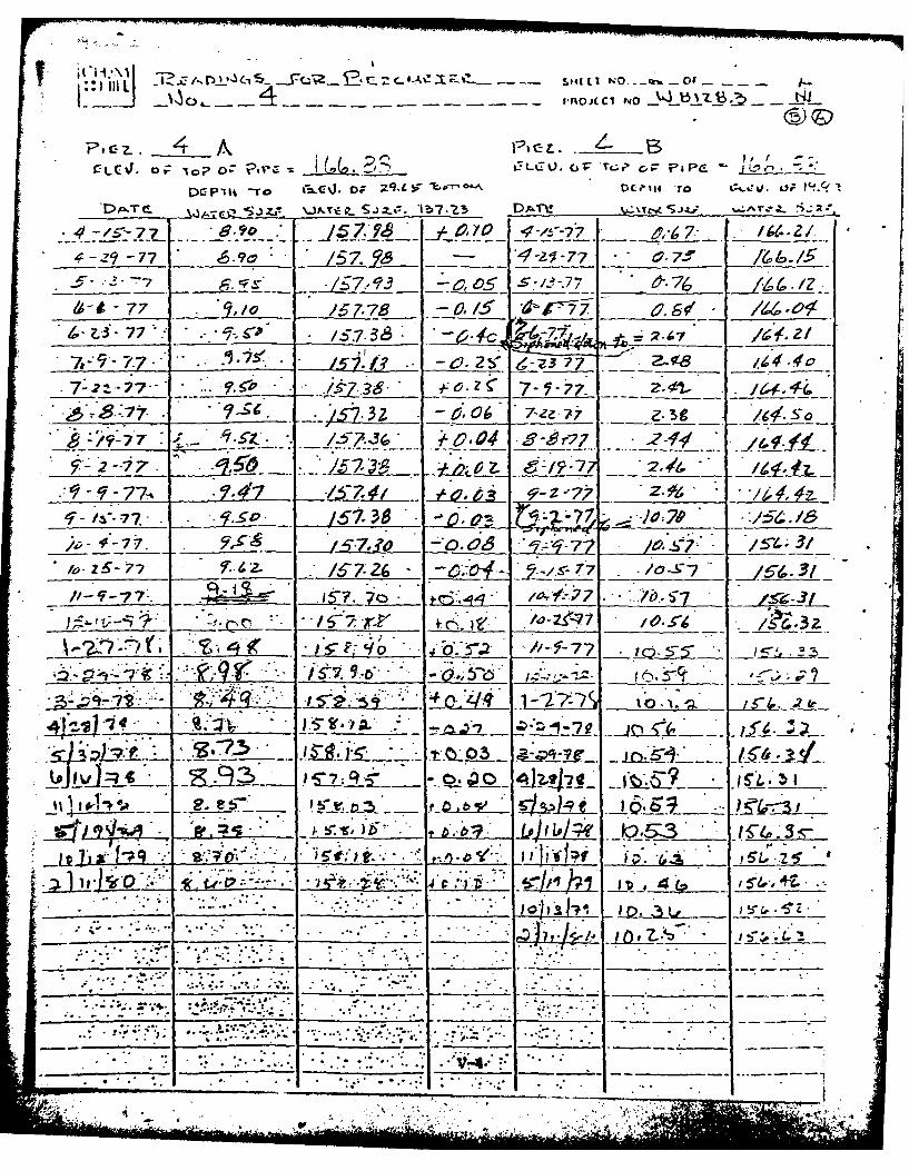
~~***IIIIStJ El-- - NO.i Of __
V'C'J LC o: ~ -tLU. C1 tL7 w r;7 P C-_. *)-
4-29-7 P.9 It ~?. -T *4-ezi-7 -r /v~
/_Sr 77 0 -* 1 9' -c 0 -13-7 .7 j, -
--- Jr 7- ~ 4r - 2
______-77 6-c 7~ 7-Z-.-77 0__ -f ._ _ _
* :'~77 ; q;../5 78~~2O 36r15 29
6- 77 .. C 0 z63 I-3
___ /57.7 - ev.T -; 7 7/ S 2__98
/'F-7'7 ro1-27. ;..iib f
2 -7 7 -
77, j ~ /5.~ -... ;;~v:.____
/4%_____ -7_ -__3___JO;_7 9
-7.~ 314
A __ - ~ f~' -~;*2 -7 7.#-.( .157 iw10 T-7iJ.i I*i"c___, 18'.d 3-Z
* .-.f * .
*~i n-".
-l P. . . *.*-
er~o 4 V4
.0 Or.
C). - -~ - - - - - - - - -- A JC NO
P, C- Z.91~
DGP1Itt -To, i-L-) D -787' C'1 o ~ t~1.
7- -77 /6 t.7 -- 7-9-77 _ /,O/~'
'7-22-77 f5.9 '417 Z7 7- 2?;7 I.i
____ -.0-.7 2-6 L J . .IL 6-S-" ///
t~ -/?9-77.* 15~5 57.~8 0 8/?-,91/ S~4
4--77___ -S-7- It ;9 A0 'Vo 7o 7 7 /.V _ .i77 7_ 1.5 75,6~' 09~6j
~~~~L 7 a t _ _4~., ~' C . ~ ILSLL:n __
~4J ~ i~m~ ___ .~ -~S. 9
- ~ ~ ~ ~ I pit;12 *24-.
. .. ..... ......
.7 7S7-

:Y' - -- - - - -- P140JE C7 N.O _ b3 z _ _t
F/
---0;7z. 'lo 0;' ?'- ?,et. pjpr-
*DC P 71t -ro *-"-C ) , OF 73.2- -. - D ll_ -To __ .
/o.7z . 7 /5 ' ,26 4-zz*:7 1,/.24 • ___.
7 7-77 .Z& -/ 1 7 _ 7 .- " O 7__
- ZZ - 77 / .* .157. I tC.2 7-2z--77 I., /:7.
6- 877 . 77 t /7. 4 . ' -S-77 /o- - 1S7.z
-:/F77"" ./.797 S0 /_ e -9-77 7 f /5 Z, !
"Z " 6. - 4 - ,0 , 4 6 ; 2 - 7 7 " ' L . .
/4 : *b -1"77 "/' __ 57 .t : _____ _._""" ____ __ . ,-S..__ I-__.___
.:_-__ -_ --,. -+_&_v/ ~~ - . 4. - __-- O"l O z_ - -- } _ . _._ f'? -' - . : - 77- __ __i6 ,__-____- -. -# &> _ . .l, * ~t_:_ = _ _o -__ _ . Iir. o _ . _-,___
, .57s #vo /Z~? /7'
. 7I
7 ,z- .- - " - - . ,_ _ _ __ . " . , ,- u---. 7 7_7 _0--j i!5 7--Zj j 9 *, 8
3 7"* <•3 b Pj fi~j i . ..* __ _
- 3-1 -,P i -:7 1 C n "
..% ...._ _.. ._~._ -"( 0 /. S ID
-t . ,--
:."*'- " ""'-" "".. . . .. . . . "-.....-:...: . .""
e
_________ _ ___ ___ _______ V,. .. .. ,.. .: ., -,- . i ..- h h
~: ':: tilL 3j~j'I~ijtL1~~ z9, ~~ L~r.~St4LL1'O.7OJ
DG II -T C);~c t2Lo 2-3~ -L- C14'oo:i,
,m. ~ - W An
.7 7 o. - .cz -c- 2 r. ~- z - -7 11-2 _ ___ __
7- 7 fl-c( 42,.' 7-71-77 -,1.09 - 57*23-7 7- ZZ-7 7 066I.S .C23 7-2.-77 /0.'?g73f
<58 * )e-.77 /5:9' -oo S -77' z____ S.1/.7:. /57.1. 7-2-7 -00 .t67 _
,, :F * 77 ___ __d _ 7, 6.19/ - IS*7 7, .530 _ __ _
-B-7-z7. - 9 - 77
___ /7.5 f-.'" /,S' __9_V_-7; -*7
f , ISt.i g 771 I-g-77 *~-~[ a, ?__9_ 7-_ __ _ _ ~ ~
*~~~3 o__ _ _ 0_ _ _ _ _4 5. *-&4 __ _
*~t rri~ 13__ _ _ . O :~~
t~~f% CY3e~~ ~~ __~____
I S- 77AL, 7- ___4
Sr.4
V-6 __ ___
4 ~ .
o~7L rnOJECI NO _W3
( - V .-
i77c . / . . 7 z
+ -22-.77 z Z _
9--- 1722. 9- r__7 17Z7 / D
z- 77_.:7- z T _ * ____: ~ -__//. L Z J..'Z 7 7 /7.~ __- ,. G
A- .-77. ./ -4 -7 - 0-477 le- _ -77 7L 3 161.____
_ ',-/0 - 717 /.7 rI-,. 160,6. - _lo -__ _ 7 .-
9-•7' 7- -7 -/z // .¢
-/ ___ -- r-- ___7____.:. I, : € _ '____ ,o,';71 .; _.o 7
7.. ;2p
,o-"- ,- . i. /0.1 " " -. ,-.-i'1 * 3;,q _____. _.
.: = -<- ___ .____ ____ ,-o..2.P ;i-1,-J r', " j . "
- -'lb ,. _ ..-,,.4 - #o.J2 i a- : .. _ - i.-l , ill . ,. .
* . .. -7 !7
. "
i. . ; .,-.t.. . . .
* 5 . . -.'... ". . .
-1 Lt. 9.-. __ " i ., 63 -Al .L , i g ui.•
.. _ .. . "'-- --
M
... .. . .... .
. . . .. .. .
.'... . ; "- :,, : . ..<• , . . . -.. =. .-. - ; ,-; .. ... -".; . .. ; -.7

RlilCtr- C--eM-e S-I4(C No.- 4- -
rniOJECI NO
_____ A."A,
pop,: c; 1: 72i~ /7 .. Q LF LCV ic. .:' c,; Papa'Tv
7 - 77 _04 7. C'31797
7Z--77 Z__~~~~ - 7-.2Z-7~ 01,4
__ _ _ -. ,77 15 -3 t7 C- _C5_9-_7;
Z _ 7.7. -..O 5.O. &Of % 77 j _
___ _ -__ L Zf.Z 77 J
.7 t.. s
* jc~ 15 . *~5* o~?* ~ ~7'0_
~ld=t~. LLqP L3~ 41 l ~ i~Iib2L_ = d
I, I? . -. .
*L 2X S
. & a.. ~ j 1 i&
S .p
7: 1
.09 =.. ~W~s
It t0 W
LU Go p 0 Iii 0 Uv.n V)I
LL. < M 0 00 M
0 I N0
0 C;~
Vu-)
,> L .V*
APPENDIX VI - REER
1. Recommended Gudelines for Safety Inspection of Dam,
Department of Army, Office of the Chief of Ergineers, 46 pp.
2. Design of Small Dam, U. S. Department of Interior, Bureau
of Reclamation, 1974, 816 pp.
3. Geologic map of Virginia, Virginia Division of Mineral
Resources, 1963
4. Geolcgy of the Virgiia Triassic, Roberts, J. K., Virginia
Division of Mineral Resources Bulletin No. 29, 1928, 205 pp.
5. Section 4, Hydrology, Part 1, Watershed planning, ScS
National Engi eering Handbook, Soil onservation Service,
U. S. Department of Agriculture, 1964.
6. Hydrcuterological Report No. 33, U. S. Department of
Comwrce, Weather Bureau, U. S. Department of Anny, Corps
of Engineers, Washington, D. C., April 1956.
.9- -