Embed Size (px)
DESCRIPTION
manual novomatic
Citation preview
© 05 2008 AGI GmbHAustrian Gaming Industries GmbH
Wiener Strasse 158 . A-2352 Gumpoldskirchen . Austria . Europe . Tel.: +43-2252-606 . www.austrian-gaming.com . e-mail: [email protected]
45M
680U
4UK-
01
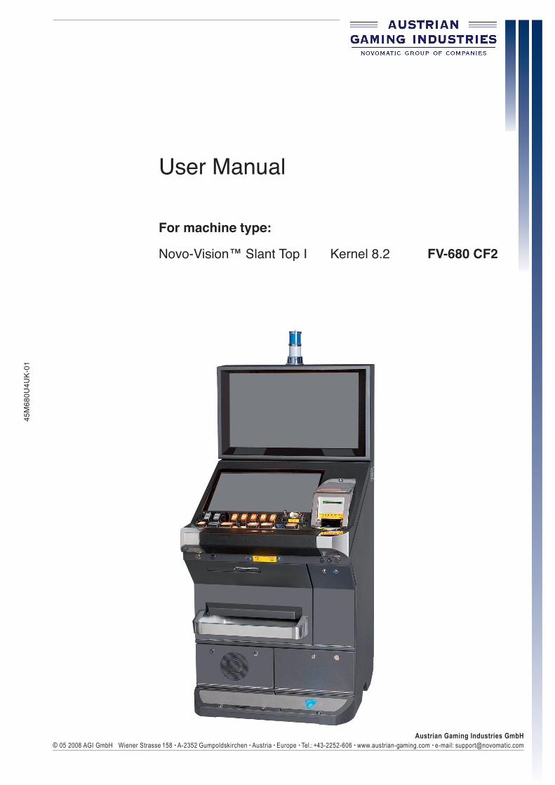
User Manual
For machine type:
Novo-Vision™ Slant Top I Kernel 8.2 FV-680 CF2

P a g e 2 © 05 2008 AGI GmbH
G E N E R A L
45M
680U
4UK-
01
All technical information contained in this manual has been developed and compiled with great care and has beenreproduced taking advantage of advanced controlling mechanisms. The manufacturer reserves the right to makechanges to this manual at any time.
AUSTRIAN GAMING INDUSTRIES GmbH gives no guarantee and accepts no legal responsibility (neither as aliability nor in any other way) for any errors and consequences that may arise from incorrect statements orincorrect use.
The author welcomes any notifications of errors or ambiguities. The product names used in this manual may be registered trademarks and / or brands of the relevant companies belonging to the Novomatic Group.All rights reserved.
Any form of reproduction (printing, photocopying or other means) of any part of this manual, and any processing,multiplying and distributing by the use of electronic systems shall be prohibited unlessAUSTRIAN GAMING INDUSTRIES GmbH has given written consent.
This manual is part of the device and must be passed on together with the device to any new owner or holderof the device. It must be kept for the whole useful life of the device and must be accessible to technical staffat all times.
The instructions contained in this manual must be strictly observed.
This manual was created in accordance with the European norm EN 62079:2001 and is valid for
Novo-Vision™ Slant Top I Series (FV-680 CF2) Kernel 8.2
until a newer manual version is released. The version number of the User Manual is indicated as theidentification number on the inner page margin.
For identification of the device refer to the ID plate attached on either side of the device.The plate also contains the required official approval symbol (CE, CSA).
space for official approval symbol
Illustr. 0.1 ID Plate
Copyright AUSTRIAN GAMING INDUSTRIES GmbHNOVOMATIC GROUP OF COMPANIESWiener Strasse 1582352 Gumpoldskirchen, Austria, EuropeInternet: www.austrian-gaming.com
Technical Support Tel.: +43 2252 606-300 Fax: +43 2252 607-001 E-Mail: [email protected]

P a g e 3© 05 2008 AGI GmbH
G E N E R A L45
M68
0U4U
K-01
About this manual
This manual is meant to be a permanent source of reference for the user. The individual sections contain important information about: •Installation •Handling •Use •Service •Repairs
This manual is divided into five sections. Each chapter explains a specific area of how to use the machine. In the enclosure you find the table of figures, the EC-declaration of conformity and the glossary.
Part I Introduction general information of the machine general information of different components and elements technical data
Part II Installation installation and initialization of the machine
Part III Troubleshooting description of possible sources of errors
Part IV Game and Software error messages of the software accounting system possibilities of configuration and initialization
Part V Hardware description of individual components and elements of the machine
Annex table of illustrations EC-Declaration of conformity glossary

P a g e 4 © 05 2008 AGI GmbH
G E N E R A L
45M
680U
4UK-
01
Table of Contents
Part I Introduction 7 I.1 Operating elements 9 I.2 Description of components 10 I.3 Machine dimensions 11
Part II Installation 13 II.1 Inspection (damages caused by transport) 15 II.2 Installation instructions 15 II.3 Power up 15 II.4 Safety precautions 16
Part III Troubleshooting 21 III.1 Lack of line voltage supply 23 III.2 Error messages of the software 24
Part IV Game and Software 25 IV.1 Error handling 27 IV.2 Remote in 69 IV.3 Handpay credit 71 IV.4 Hopperrefill 73 IV.5 Hopper dump 75 IV.6 Out of Service (Locking of the machine) 77 IV.7 Top light 79 IV.8 Audit Menu 81 IV.9 RAM Clear 136
Part V Hardware 137 V.1 Power Supply 141 V.2 Bill acceptor 147 V.3 Coin acceptor 159 V.4 Hopper 167 V.5 Monitors and Touchscreen Controller 171 V.6 COOLFIRE II Motherboard 177 V.7 COOLFIRE II Backplane 185 V.8 Key Panel Module 199 V.9 Top light 203 V.10 Illumination 207 V.11 Mechanical meters 211 V.12 Door switches 215 V.13 Loudspeakers 219 V.14 Ticket printer 225 V.15 Preventative maintenance 241
Annex 249 Table of illustrations 251 EC-Declaration of Conformity 253 Glossary 254

P a g e 5© 05 2008 AGI GmbH
G E N E R A L45
M68
0U4U
K-01
Legend
DANGER Warns of dangerous situations to the user (e. g. risk of electric shock).
ATTENTION Special, situation-related and action-related danger warnings.
INFORMATION Provides further information and/or explanation.
NOTE Provides additional instructions and tips.
TROUBLESHOOTING Explains the debugging of errors.
Refers to a related subject / part of this manual.
!

P a g e 6 © 05 2008 AGI GmbH
G E N E R A L
45M
680U
4UK-
01
Technical Data
ManufacturerAustrian Gaming Industries GmbH Wiener Strasse 158 A-2352 Gumpoldskirchen Austria
Machine typeNovo-Vision™ Slant Top I FV-680 CF2 (Video)
Dimensions in mm (l x h x d)710 x 1638 x 805
Weightapprox. 166 kg
Power supply230 V / 50 Hz / 1,6 A resp. 110 V / 60 Hz
Power250 W
FusesT 3 A 15 (230 V) T 5 A (12 V)
Favourable operating temperature in °C10 - 35
Humidity in %30 % - 80 % (non-condensing)
Place of identification detailsID-Plate on the side of the machine.
Thermal dangerCertain parts become hot during operation and cause injuries!
Electrical dangerWhenever the machine is open, voltaged parts can be touched!Power down the machine whenever you do repair or maintenance work!
Mechanical dangerNote that some flanges within the device are sharp-edged and cause injuries!Improper handling and closing of the device can lead to contusion!

© 05 2008 AGI GmbHAustrian Gaming Industries GmbH
Wiener Strasse 158 . A-2352 Gumpoldskirchen . Austria . Europe . Tel.: +43-2252-606 . www.austrian-gaming.com . e-mail: [email protected]
45M
680U
4UK-
01
Part I Introduction
I.1 Operating elements
I.2 Description of components
I.3 Machine dimensions

P a g e 8 © 05 2008 AGI GmbH
I N T R O D U C T I O N
45M
680U
4UK-
01

P a g e 9© 05 2008 AGI GmbH
I N T R O D U C T I O N45
M68
0U4U
K-01
I.1 Operating elements
Z_FV680CF2_NovoVisionSlantTopI_Bedienelemente_Front.eps
Illustr. I.1.1 Operating elements
1 ID Plate 2 Top Large Door 3 Coin slot 4 Ticket out 5 Bill insertion 6 Door lock 7 Top Large Door lever
3
456789
1011
1213
1
2
Z_FV680CF2_NovoVisionSlantTopI_Bedienelemente_Side.eps
8 Attendant keyswitch 9 Front Large Door lever 10 Stacker Door 11 Front Large Door 12 Drop Door (right) 13 Drop Door (left) with woofer

P a g e 1 0 1 0 © 05 2008 AGI GmbH
I N T R O D U C T I O N
45M
680U
4UK-
01
I.2 Description of components
Z_FV680CF2_NovoVisionSlantTopI_Komponenten.eps
Illustr. I.2.1 Description of components
1 Top light 2 Monitor 3 Coin acceptor 4 Switch module incl. main switch 5 Mechanical meters 6 COOLFIRE II Motherboard
(with Logic Door lock) 7 COOLFIRE II Backplane
8 Loudspeaker (lightbox) 9 Ticket printer 10 Bill acceptor 11 Stacker 12 Hopper 13 Switching power supply 14 Power distribution box 15 Woofer
Z_FV680CF2_NovoVisionSlantTopI_Bedienelemente_Front.eps
6
7
8
9
10
1112
1314
1
2
4
5
3
15
P a g e 11 11© 05 2008 AGI GmbH
I N T R O D U C T I O N45
M68
0U4U
K-01
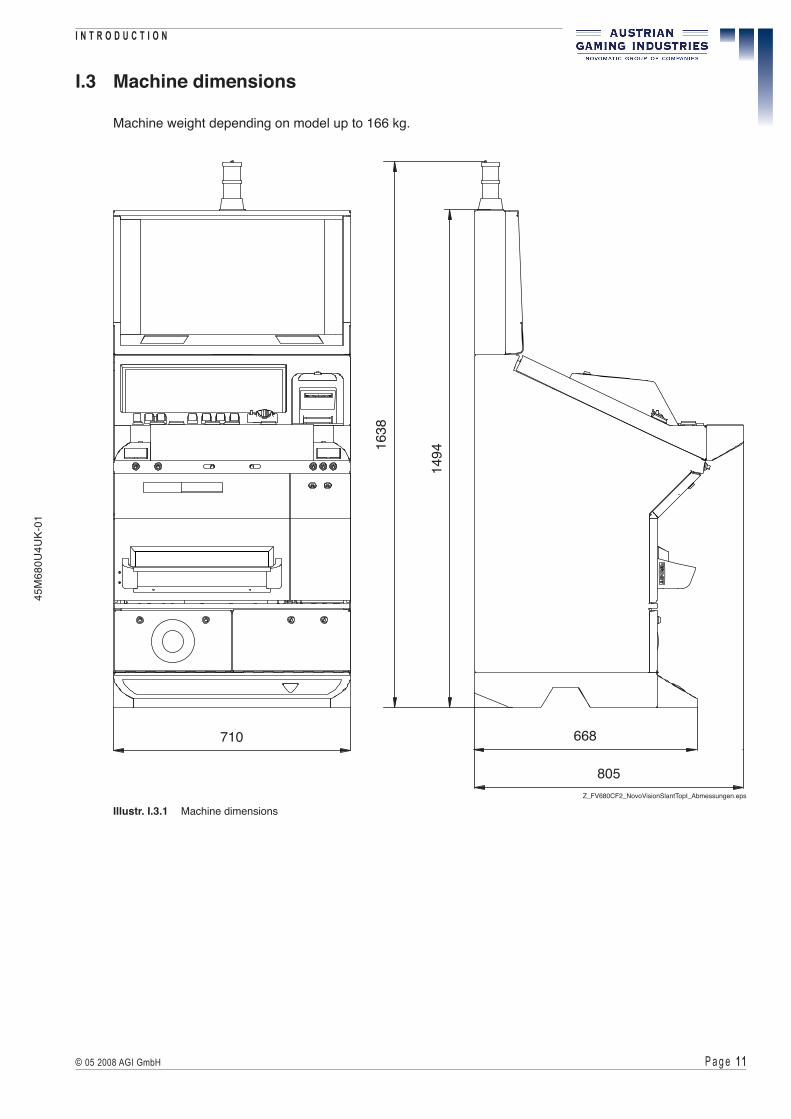
I.3 Machine dimensions
Machine weight depending on model up to 166 kg.
Z_FV680CF2_NovoVisionSlantTopI_Abmessungen.eps
710 668
805
149416
38
Illustr. I.3.1 Machine dimensions

P a g e 1 2 1 2 © 05 2008 AGI GmbH
I N T R O D U C T I O N
45M
680U
4UK-
01

© 05 2008 AGI GmbHAustrian Gaming Industries GmbH
Wiener Strasse 158 . A-2352 Gumpoldskirchen . Austria . Europe . Tel.: +43-2252-606 . www.austrian-gaming.com . e-mail: [email protected]
45M
680U
4UK-
01
Part II Installation
II.1 Inspection (damages caused by transport)
II.2 Installation instructions
II.3 Power up
II.4 Safety precautions

P a g e 1 4 1 4 © 05 2008 AGI GmbH
I N S T A L L A T I O N
45M
680U
4UK-
01

P a g e 1 5 1 5© 05 2008 AGI GmbH
I N S T A L L A T I O N45
M68
0U4U
K-01
II.1 Inspection (damages caused by transport)
1) Remove the shipping carton and the material used to secure machine components during transport (necessary only for some types of cabinet).
2) Should any damages caused by transport have occurred on the exterior, report them immediately to the sender and have them confirmed by the same.
II.2 Installation instructions
It must be ensured that the machine is operated in an upright position. All machines of the Novo-Vision™ Slant Top I Serie can be positioned close to each other. The minimum distance to a possible back wall or the like should be 10 cm..
II.3 Power up
1) Before start check the line voltage. The machine has been designed to sustain 230 V ± 10 %, 50 Hz or 110 V ± 10 %, 60 Hz. Make sure that the line voltage corresponds to the voltage indicated on the machine.
2) As all machines of the Novo-Vision™ Slant Top I Serie are equipped with an earthing connection, it should be ensured that the main supply is also equipped with an earthing connection.
3) Plug in the main plug correctly. 4) Open the Top Large Door. 5) If the machine is equipped with a coin comparitor, place the reference coin in there. 6) Refill the hopper. 7) Switch on the machine. 8) Close the Top Large Door. 9) After a short self test the machine is ready for operation. 10) Credits can be added and a new game can be started.

P a g e 1 6 1 6 © 05 2008 AGI GmbH
I N S T A L L A T I O N
45M
680U
4UK-
01
II.4 Safety precautions
For operating safety and to avoid damage to the machine, read carefully and observe the following instructions.
Because the attendee responsible for usual maintenance has to open the machine, he has to get informed about the safety precautions.
There are static-sensitive parts inside the machine which could be damaged by electric discharge. Ground yourself by touching a ground strap inside the machine to neutralize electric charges before changing or maintaining inner parts.
Ground straps inside machine are marked with yellow stickers.
DANGERIn case of emergency power off the machine!
Only disconnect the power line from the outlet achieves a powerless machine! For machine with uninterruptible power supply (UPS) you have to switch it off, too!
Unplugging the machine with wet hands can result in a risk of electric shock!
If there are unusual smells or sounds coming from the machine, unplug the unit from the AC outlet immediately and for machines with an UPS power it off, too. Contact a qualified service personnel. Continued operation may be dangerous and can result in a risk of fire or electric shock.
Do not open the cabinet by force There are potentially dangerous high voltage components inside. Opening the cabinet can result in a serious risk of fire hazard or electric shock. There are no user serviceable parts inside. Refer all service to qualified service personnel.
Never insert objects into the cabinet ventilation openings Do not push any objects through cabinet ventilation slots as they may touch dangerous voltage points or cause short circuits that could result in a risk of fire or electric shock.
Never spill liquid of any kind (coffee, wine, etc.) on the machine. In case of an accident, this may result in a risk of fire or electric shock. Unplug the unit and have it checked by qualified service personnel. Never use a water jet to clean the device! Do not use organic solvent like thinner or abrasive materials to clean the device!

P a g e 1 � 1 �© 05 2008 AGI GmbH
I N S T A L L A T I O N45
M68
0U4U
K-01
Avoid damages to the wires
Do not lead anything onto the power cord and do not bruise or stretch any wires. Damaged wires can result in a risk of fire or short circuit. Keep the wires away from where people will walk on them or stumble and be injured.
ATTENTION
Environment
Suitable for indoor use only! Do not expose the machine under any circumstances to rain or temperatures greater than 50° C. The operating temperature must not exceed 35° C. If the machine has been exposed to very low temperatures, do not power up it immediately. The machine has to reach room temperature (convenient temperature is 10° C to 35° C).
Be aware not to exceed the operation humidity range of 30 % to 80 % (not condensing).
Do not install it close to radiator heating either. Do not install the machine in locations with rapidly changing temperatures or excessive dust. This could cause the risk of fire hazard, short circuit or other damages.
Provide adequate space for ventilation
Opening on top, sides and in the bottom of the cabinet are provided for ventilation. To ensure proper operation and to prevent overheating, these openings should not be blocked or covered. To allow hot air to escape make sure that there is a minimum space of 10 cm between the machine and a wall or alike. If the machine becomes too hot, it might cause a fire hazard.
!

P a g e 1 8 1 8 © 05 2008 AGI GmbH
I N S T A L L A T I O N
45M
680U
4UK-
01
MISCELLANEOUS
Influence of magnetic fields
Do not install machines with CRT monitors close to strong magnetic fields like loudspeakers or fluorescent lamps. Those equipments could bias the monitor, unusual noises could be heard.
Machines with LCD monitor
Do not hit or scratch the surface. High pressure of sharp objects could cause irreparable damages. To clean the surface use some absorbent cotton or soft cloth and a window cleaner. If the display accidentally breaks and the liquid crystal material leaks, it should be kept away from the eyes or mouth. In case of contact with hands, legs or clothes, it must be washed away thoroughly with soap.
NOTE
If you follow these instructions closely and the machine is maintained and handled in a proper way, it complies with the usual safety standards. The manufacturer warns explicitly against predictable, unconventional use of the machine as well as predictable malpractice. Do not bypass the built-in safety precautions in the machine! Arbitrary alterations and changes of the machine are prohibited for safety reasons. For security reasons any changes and exchanges of defective parts have to be accomplished with originally or manufacturer-registered parts. The manufacturer calls attention to the fact that spare parts that were not delivered by the Austrian Gaming Industries are neither tested or approved by AGI. The installation and/or use of such parts might negatively affect the machine’s performance. The manufacturer cannot be held responsible for errors that result from such parts.
We hereby disclaim any warranties for improper handling of the machine.
P a g e 1 9 1 9© 05 2008 AGI GmbH
I N S T A L L A T I O N45
M68
0U4U
K-01
ATTENTION
The following service instructions are for use by qualified or trained personnel only. The owner of the machine has to assure that only qualified or trained personnel perform services. To avoid personal injury or damage to the equipment, do not perform any servicing other than such contained in this manual.
!

P a g e 2 0 2 0 © 05 2008 AGI GmbH
I N S T A L L A T I O N
45M
680U
4UK-
01

© 05 2008 AGI GmbHAustrian Gaming Industries GmbH
Wiener Strasse 158 . A-2352 Gumpoldskirchen . Austria . Europe . Tel.: +43-2252-606 . www.austrian-gaming.com . e-mail: [email protected]
45M
680U
4UK-
01
Part III Troubleshooting
III.1 Lack of line voltage supply
III.2 Error messages of the software

P a g e 2 2 2 2 © 05 2008 AGI GmbH
T R O U B L E S H O O T I N G
45M
680U
4UK-
01

P a g e 2 3 2 3© 05 2008 AGI GmbH
T R O U B L E S H O O T I N G45
M68
0U4U
K-01
ATTENTIONEach power up is followed by a short self test. Then the machine is ready for operation.If this is not the case, check the machine for the following possible error sources.
III.1 Lack of line voltage supply
The power supply is primary secured at 230 V with two T3A15 inert single-pole fuses. The primary fuses are located on the front of the main switch module (illustr. III.1.1).
Such voltage indications facilitate servicing and are an initial source of information. However, more details regarding (a) defective line voltage(s) can only be given by measurements with suitable devices.
If the error cannot be cleared, please see part V - Power supply for further information.
!
!Illustr. III.1.1 Main switch with fuses
ATTENTIONUsually errors in the electronics can only be handled by an expert.The exchange of parts is the quickest way to perform a repair if this is eventually necessary.If no spare parts are at hand, make use of our technical support and send us the defectiveelectronic part together with a short error description.
F_40000094.jpg
fuses T3A15
main switch

P a g e 2 4 2 4 © 05 2008 AGI GmbH
T R O U B L E S H O O T I N G
45M
680U
4UK-
01
III.2 Error messages of the software
After the machine has been powered up, the major parts of the machine (e.g. hopper, CPU board etc.) are subject to a self test.
If this test has been successful, the machine switches automatically to the ready-for-play status. The error management engages each malfunction and/or manipulation is detected.
If the machine detects an error, the corresponding code is shown on the screen (see illustr. III.2.1).
Error handling (procedures to rectify an error):
1) Turn the attendant key. 2) Clear the error. 3) Release the attendant key. 4) Usually the machine should now be ready for operation again.
If an error cannot be cleared this way, see part IV - Game and Software.
S_Fehleranzeige_UK.eps
Illustr. III.2.1 Error display

© 05 2008 AGI GmbHAustrian Gaming Industries GmbH
Wiener Strasse 158 . A-2352 Gumpoldskirchen . Austria . Europe . Tel.: +43-2252-606 . www.austrian-gaming.com . e-mail: [email protected]
45M
680U
4UK-
01
Part IV Game and Software
IV.1 Error handling
IV.2 Remote in
IV.3 Handpay credit
IV.4 Hopper refill
IV.5 Hopper dump
IV.6 Out of Service (Locking of the machine)
IV.7 Top light
IV.8 Audit Menu
IV.9 RAM Clear

P a g e 2 6 2 6 © 05 2008 AGI GmbH
G A M E & S O F T W A R E
45M
680U
4UK-
01

P a g e 2 � 2 �© 05 2008 AGI GmbH
G A M E & S O F T W A R E45
M68
0U4U
K-01
IV.1 Error handling
Illustr. IV.1.1 Attendant keyswitch for error handlingZ_FV680CF2_NovoVisionSlantTopI.jpg
attendant keyswitch
If an error occurs, the machine will interrupt the current game and switch automatically to failure mode.
1) An acoustic signal can be heard. 2) The blue light of the top light is flashing slowly. 3) The error message together with a short error description is shown in the middle of the screen
(see illustr. IV.1.2 and IV.1.3). Below the procedure how to clear the error is explained.

P a g e 2 8 2 8 © 05 2008 AGI GmbH
G A M E & S O F T W A R E
45M
680U
4UK-
01
IV.1.1 Explanation for clearing errors
1) Locate the error code according to the tables on the next pages.
2) Activate the attendant keyswitch (acoustic signal stops). The program switches to or remains in the AUDIT MENU. Clear the error.
3) Release the attendant keyswitch. The machine switches back to the game mode, already existing credits remain
(except if a RAM Clear has been performed!).
If more errors occur, activate the attendant keyswitch until all errors have been cleared. If an error cannot be cleared this way, follow the instructions of the error code table.
Errors are displayed in two ways:
Internal errors (always called E 99 9):
S_FehlerCF2_E_99_9_UK.jpg
Illustr. IV.1.2 Internal error - Screenshot
S_FehlerCF2_E_2101_UK.jpg
Illustr. IV.1.3 Error message - Explanation of elements
Error code Error name
Error handling
Note the error and inform our technical support (+43 2252 606-300) about it.
Other errors

P a g e 2 9 2 9© 05 2008 AGI GmbH
G A M E & S O F T W A R E45
M68
0U4U
K-01
INFORMATION Some errors demand a RAM Clear.Find out more about RAM Clear at part IV.9.
ATTENTIONIf an error message is triggered by a malfunction of non-activation of individual meters the device must be removed from operation and the meters circuit board must be exchanged.
ATTENTIONIf any hardware components like stacker box, hopper or coin acceptor are missing, no start-up of the machine is possible.Before the start-up screen is displayed, an error message appears on the screen.Quitting this error can force restart of the machine but new appearing of this error message (depends on software version and missing components).
TROUBLESHOOTINGSwitch off the machine and replace the missing hardware component. Now after restarting the machine the error can be cleared by turning the attendant keyswitch.
For further information see the following error handling table!
!
!

P a g e 3 0 3 0 © 05 2008 AGI GmbH
G A M E & S O F T W A R E
45M
680U
4UK-
01
IV.1.2 Overview of possible errors
Event messages (can be viewed in the AUDIT MENU under EVENTS)
27 8 - Stacker full27 10 - Bill rejected27 11 - Bill excessive reject33 2 - Ticket low34 3 - Hopper full50 2 - Real time clock modified50 3 - Periodic memory cleared50 4 - System shutdown50 5 - System power up50 6 - System restart61 11 - RAM error recovered61 12 - RAM error recovered61 13 - RAM error recovered61 14 - RAM error recovered61 21 - RAM error recovered61 22 - RAM error recovered61 23 - RAM error recovered61 24 - RAM error recoveredEE 03 - Game disabled by networkEE 04 - Game resumed by networkEE 05 - Machine initializedEE 06 - Service mode enteredEE 07 - Service mode leftEE 08 - Configuration option changed
Warning messages (can be viewed in the AUDIT MENU under EVENTS)
63 3 - Main door open63 6 - Door in door openEE 02 - Game disabled by network

P a g e 3 1 3 1© 05 2008 AGI GmbH
G A M E & S O F T W A R E45
M68
0U4U
K-01
Error messages of the battery
12 3 - RAM Battery low12 4 - RAM Battery empty12 5 - Real time clock failure12 6 - Serial communication failure12 61 - Serial communication failure12 62 - Serial communication failure12 63 - Serial communication failure12 7 - Mainboard hardware failure12 8 - Real time clock not set
Error messages of the coin acceptor
21 0 - Diverter error21 1 - Coin optics failure21 2 - Coin in jam21 3 - Coin acceptor wrong pulse21 4 - Coin acceptor disconnected21 5 - Coin yo-yo (coin reverse)21 6 - Top diverter optics disconnected21 7 - Bottom diverter optics disconnected21 8 - Coin diverter disconnected21 9 - Coin acceptor currency mismatch21 A - Coin acceptor missing21 B - Coin acceptor ROM error21 C - Coin acceptor RAM error21 D - Coin acceptor CRC error21 E - Coin acceptor configuration error21 F - Generic coin acceptor error21 G - Coin acceptor power fail21 H - Coin acceptor battery low21 J - Coin acceptor firmware version wrong
Error messages of the bill acceptor
27 0 - Power up with bill in acceptor27 1 - Power up with bill in stacker27 2 - Jam in bill acceptor27 3 - Jam in stacker27 4 - Bill Acceptor disconnected27 5 - No stacker box27 6 - Bill acceptor cheated27 7 - Bill acceptor failure27 9 - Bill acceptor currency mismatch27 A - Bill acceptor failure27 B - Bill acceptor failure27 C - Bill acceptor failure27 D - Bill acceptor failure
P a g e 3 2 3 2 © 05 2008 AGI GmbH
G A M E & S O F T W A R E
45M
680U
4UK-
01
27 E - Bill acceptor failure27 F - Bill acceptor failure27 G - Bill acceptor failure27 H - Bill acceptor failure27 J - Bill acceptor failure27 K - Bill acceptor failure27 L - Bill acceptor failure27 M - Bill acceptor missing27 N - Bill acceptor ROM error27 P - Bill acceptor RAM error27 Q - Bill acceptor CRC error27 R - Bill acceptor configuration error27 S - Generic bill acceptor error27 T - Bill acceptor power fail27 U - Bill acceptor battery low27 V - Bill acceptor firmware version wrong
Error messages of the COMM port
28 A - COMM port missing28 B - COMM port ROM error28 C - COMM port RAM error28 D - COMM port CRC error28 E - COMM port configuration error28 F - Generic COMM port error28 G - COMM port power fail28 H - COMM port battery low28 J - COMM port firmware version wrong
Error messages of the ticket printer
33 0 - Printer is disconnected33 1 - Printer is not ready33 3 - No ticket33 4 - Paper jam33 5 - Error during printing
Error messages of the hopper
34 0 - Hopper disconnected34 1 - Hopper tilt34 2 - Hopper low34 4 - Hopper limit reached34 5 - Hopper coin out jam34 6 - Hopper empty34 7 - Hopper pulse not in tolerance34 8 - Hopper optics failure34 9 - Hopper currency mismatch34 A - Hopper missing

P a g e 3 3 3 3© 05 2008 AGI GmbH
G A M E & S O F T W A R E45
M68
0U4U
K-01
34 B - Hopper ROM error34 C - Hopper RAM error34 D - Hopper CRC error34 E - Hopper configuration error34 F - Generic hopper error34 G - Hopper power fail34 H - Hopper battery low34 J - Hopper firmware version wrong34 K - Hopper changed
Error messages of the limits
35 0 - Credit limit reached35 1 - LA win limit reached35 2 - Jackpot limit reached35 3 - Jackpot won35 4 - Jackpot limit reached35 5 - Cash button pressed35 6 - Residual ticket printout failure35 7 - Noncash win
Error messages of the physical reels
4 1 - Undefined error at reel X4 2 - Sensor 1 error at reel X4 3 - Sensor 2 error at reel X4 4 - Sensor 1 not found at reel X4 5 - Sensor 2 not found at reel X4 6 - Reel X manually moved4 8 - Wrong returnposition at reel X4 9 - Reel X software has changed4 10 - Reel X software wrong4 11 - Reel X interface changed4 12 - Reel interface X ROM error4 13 - Reel interface X not responding4 A - Reels missing4 B - Reels ROM error4 C - Reels RAM error4 D - Reels CRC error4 E - Reels configuration error4 F - Generic reels error4 G - Reels power fail4 H - Reels battery low4 J - Reels firmware version wrong4 99 - Reels configuration error

P a g e 3 4 3 4 © 05 2008 AGI GmbH
G A M E & S O F T W A R E
45M
680U
4UK-
01
Error messages of the RAM
61 - RAM error62 0 - ROM CRC error62 1 - CF card CRC error63 0 - Logic area was open63 1 - Logic area open63 2 - Drop door open63 4 - Stacker door open63 5 - Maindoor optic error63 6 - Printer door open63 7 - Bill door open63 8 - Service door open65 0 - Bad EEPROM65 1 - EEPROM CRC check failed65 2 - EEPROM configuration mismatch65 3 - EEPROM structure mismatch65 4 - EEPROM changed65 5 - Coin/hopper denomination mismatch68 0 - Program ROM changed
Error messages of the blackbox
69 0 - Blackbox inoperable69 1 - Blackbox CRC check failed
Error messages of the physical lightwheel
7 00 - Undefined error at lightwheel7 09 - Lightwheel software has changed7 10 - Lightwheel software wrong7 12 - Lightwheel interface ROM error7 13 - Lightwheel interface not responding
Error messages of the 7-segment display
76 0 - Digit display not responding76 1 - Digit display ROM CRC failed76 2 - Digit display ID CRC failed76 A - Digit missing76 B - Digit ROM error76 C - Digit RAM error76 D - Digit CRC error76 E - Digit configuration error76 F - Generic digit error76 G - Digit power fail76 H - Digit battery low76 J - Digit firmware version wrong
P a g e 3 5 3 5© 05 2008 AGI GmbH
G A M E & S O F T W A R E45
M68
0U4U
K-01
Error messages of the touchscreen
80 0 - Touch screen missing80 1 - Touch screen invalid response80 2 - Touch screen invalid checksum80 3 - Touch screen controller error80 4 - Touch screen firmware version wrong
Error messages of the mechanical meters
81 0 - Meter missing81 1 - Meter ROM error81 2 - Meter RAM error81 3 - Meter CRC error81 4 - Meter configuration error81 5 - Generic meter error81 6 - Meter power fail81 7 - Meter battery low81 8 - Meter firmware version wrong81 9 - Meter changed
Error messages of the USB host-to-host bridge
B 1 - USB host-to-host bridge disconnected
Error messages of the cashless transfer
CL 1 - Cashless transfer failed
Error messages of the doorlogger
DL 1 - Doorlogger interface not respondingDL 2 - ROM CRC errorDL 3 - RAM Battery low
Error messages of the device processing
DP 1 - New device foundDR 2 - Device driver error
Error messages of the system
E0 - Init Machine requiredE0 1 - Init Game requiredE2 - RAM test failedE7 0 - Meters were disconnectedE7 1 - Meters disconnectedE7 2 - SIMM write line manipulatedE7 3 - Out of service

P a g e 3 6 3 6 © 05 2008 AGI GmbH
G A M E & S O F T W A R E
45M
680U
4UK-
01
Error messages of the game selector (Dongle)
ED 1 - The Game Selector is manipulatedED 4 - Game Selector: time limit exceededED 5 - Game Selector: game limit exceededED 6 - Game Selector: wrong machine numberED 7 - Game Selector: wrong machine versionED 8 - Game Selector: Version conflictED 9 - Game Selector: Timeout occurredED A - The Game Selector is missingED B - Game selector ROM errorED C - Game selector RAM errorED D - Game selector CRC errorED E - Game selector configuration errorED F - Generic game selector errorED G - Game selector power failED H - Game selector battery lowED J - Game selector firmware version wrongED K - More than one gameselector found
Error messages of the jackpot controller
EE 11 - Jackpot controller missingEE 12 - Jackpot communication lost
Error messages of the bet limit violations and invalid game objects
GA 0 - Bet limits lower than lowest game betGA 1 - Invalid bet limitsGA 2 - Missing currency configuration
Error messages of the jackpot display
JD 1 - Display not respondingJD 2 - Display software wrongJD A - Display missingJD B - Display ROM errorJD C - Display RAM errorJD D - Display CRC errorJD E - Display configuration errorJD F - Generic display errorJD G - Display power failJD H - Display battery lowJD J - Display firmware version wrong

P a g e 3 � 3 �© 05 2008 AGI GmbH
G A M E & S O F T W A R E45
M68
0U4U
K-01
Error messages of the key panel module
KP 0 - Keybord missingKP 1 - Keyboard ROM errorKP 2 - Keyboard RAM errorKP 3 - Keyboard CRC errorKP 4 - Keyboard configuration errorKP 5 - Generic keyboard errorKP 6 - Keyboard power failKP 7 - Keyboard battery lowKP 8 - Keyboard firmware version wrong
Error messages of the dynamic memory
ME 0 - 128 MB dynamic memory requiredME 1 - 256 MB dynamic memory requiredME 2 - 512 MB dynamic memory required
Error messages of the net device
ND 0 - Net device missingND 1 - Net device ROM errorND 2 - Net device RAM errorND 3 - Net device CRC errorND 4 - Net device configuration errorND 5 - Generic net device errorND 6 - Net device power failND 7 - Net device battery lowND 8 - Net firmware version wrong
Error messages of the power supply
PF 1 - Power fail procedure not executed
Error messages of the external random generator
RNG 1 - RNG data corruptedRNG 2 - External RNG: Communication CRC errorRNG 3 - Random generator not readyRNG 4 - External RNG disconnected
Error messages of the stake and prize
ST 1 - Stake, prize or percentage invalid
Error messages of the Coolfire board
99 9 - Internal Error

P a g e 3 8 3 8 © 05 2008 AGI GmbH
G A M E & S O F T W A R E
45M
680U
4UK-
01
IV.1.3 Error handling table in numeric order
12 3 - RAM Battery low Handling: Turn/release the attendant key. If the error cannot be cleared, the mainboard has to be exchanged ( see part V - COOLFIRE II Motherboard). If the machine has been switched off it may loose data or receive wrong data.
12 4 - RAM Battery empty Handling: Turn/release the attendant key. If the error cannot be cleared, the mainboard has to be exchanged ( see part V - COOLFIRE II Motherboard). If the machine has been switched off it may loose data or receive wrong data.
12 5 - Real time clock failure Handling: Turn/release the attendant key. If the error cannot be cleared, the mainboard has to be exchanged ( see part V - COOLFIRE II Motherboard). If the machine has been switched off it may loose data or receive wrong data.
12 6 - Serial communication failure Handling: Turn/release the attendant key. If the error cannot be cleared, check the network cables.
12 61 - Serial communication failure Handling: Turn/release the attendant key. If the error cannot be cleared, check the network cables.
12 62 - Serial communication failure Handling: Turn/release the attendant key. If the error cannot be cleared, check the network cables.
12 63 - Serial communication failure Handling: Turn/release the attendant key. If the error cannot be cleared, check the network cables.

P a g e 3 9 3 9© 05 2008 AGI GmbH
G A M E & S O F T W A R E45
M68
0U4U
K-01
12 7 - Mainboard hardware failure Handling: Turn/release the attendant key. If the error cannot be cleared, the mainboard has to be exchanged ( see part V - COOLFIRE II Motherboard).
12 8 - Real time clock not set Handling: Perform a RAM Clear ( see part IV.9 - RAM Clear). Turn the attendant key and open the Main Door. Set current date and time in the real time clock ( see part IV.8 - AUDIT MENU > MACHINE SETUP > INITIAL SETUP). Close the Main Door and release the attendant key.
21 0 - Diverter error Handling: Turn/release the attendant key. If the error cannot be cleared, open the Main Door and power down the machine. Check the coin diverter and the coin channels for jammed coins. Also check the connecting plugs and the cables of the magnet. Power-up the machine and close the Main Door. Perform the coin diverter test ( see part IV.8 - AUDIT MENU > DIAGNOSTICS > COIN DIVERTER TEST). If the error cannot be cleared, the coin diverter or the coin acceptor should be changed. Also, the sensors may be defective, or may need to be re-adjusted.
21 1 - Coin optics failure Handling: Turn/release the attendant key. If the error cannot be cleared, open the Main Door and power down the machine. Check the coin acceptor and the coin channel optics for dirt or damage. Furthermore check the connectors and the cables of the coin optics and the coin acceptor. The coin optics have to be placed in the centre of the borings, the optical line between transmitter and receiver must not be blocked. Power up the machine and close the Main Door. If the error cannot be cleared, the coin acceptor or the coin optics have to be exchanged ( see part V - Coin acceptor).
21 2 - Coin in jam Handling: Turn/release the attendant key. Turn/release the attendant key. If the error cannot be cleared, open the Main Door and power down the machine. The coin optics of the coin channel was blocked too long or a coin is stuck. Remove coins stuck and check the connectors and cables of the coin optics. Power up the machine and close the Main Door.
21 3 - Coin Acceptor wrong pulse Handling: Turn/release the attendant key. If the error cannot be cleared, open the Main Door and power down the machine. Check the coin acceptor for any signs of manipulation attempts. Check the connectors and the cables of the coin acceptor systematically. Power up the machine and close the Main Door. If the error cannot be cleared, the coin acceptor has to be exchanged ( see part V - Coin acceptor).

P a g e 4 0 4 0 © 05 2008 AGI GmbH
G A M E & S O F T W A R E
45M
680U
4UK-
01
21 4 - Coin acceptor disconnected Handling: Turn/release the attendant key. If the error cannot be cleared, open the Main Door and power down the machine. Check the connectors and the cables of the coin acceptor systematically. Power up the machine and close the Main Door. If the error cannot be cleared, the coin acceptor has to be exchanged ( see part V - Coin acceptor).
21 5 - Coin yo-yo (coin reverse) Handling: Turn/release the attendant key. If the error cannot be cleared, open the Main Door and power down the machine. Check the coin acceptor for any signs of manipulation attempts. Furthermore, please check if a reference coin is placed in the coin comparitor. Check the connectors and cables of the coin acceptor systematically. Power up the machine and close the Main Door. If the error cannot be cleared, the coin acceptor or the coin diverter has to be exchanged ( see part V - Coin acceptor). Also, the sensors may be defective, or may need to be re-adjusted.
21 6 - Top diverter optics disconnected Handling: Turn/release the attendant key. If the error cannot be cleared, open the Main Door and power down the machine. Check the connectors and the cables of the top coin optics. Power up the machine and close the Main Door. If the error cannot be cleared, the top coin optics have to be exchanged.
21 7 - Bottom diverter optics disconnected Handling: Turn/release the attendant key. If the error cannot be cleared, open the Main Door and power down the machine. Check the connectors and the cables of the bottom coin optics. Power up the machine and close the Main Door. If the error cannot be cleared, the bottom coin optics have to be exchanged.
21 8 - Coin diverter disconnected Handling: Turn/release the attendant key. If the error cannot be cleared, open the Main Door and power down the machine. Check the connectors and the cables of the coin diverter. Power up the machine and close the Main Door.
21 9 - Coin acceptor currency mismatch Handling: Turn/release the attendant key. If the error cannot be cleared, open the Main Door and power down the machine. Ensure that the coin acceptor is properly seated. Power up the machine and close the Main Door.
21 A - Coin acceptor missing Handling: Turn/release the attendant key. If the error cannot be cleared, check the connections of the coin acceptor.

P a g e 4 1 4 1© 05 2008 AGI GmbH
G A M E & S O F T W A R E45
M68
0U4U
K-01
21 B - Coin acceptor ROM error Handling: Turn/release the attendant key. If the error cannot be cleared, open the Main Door and power down the machine. Check the coin acceptor. Power up the machine and close the Main Door.
21 C - Coin acceptor RAM error Handling: Perform a RAM Clear ( see part IV.9 - RAM Clear).
21 D - Coin acceptor CRC error Handling: Turn/release the attendant key. If the error cannot be cleared, open the Main Door and power down the machine. Check the coin acceptor. Power up the machine and close the Main Door.
21 E - Coin acceptor configuration error Handling: Turn/release the attendant key. If the error cannot be cleared, open the Main Door and power down the machine. Check the coin acceptor. Power up the machine and close the Main Door.
21 F - Generic coin acceptor error Handling: Turn/release the attendant key. If the error cannot be cleared, open the Main Door and power down the machine. Check the coin acceptor. Power up the machine and close the Main Door.
21 G - Coin acceptor power fail Handling: Turn/release the attendant key. If the error cannot be cleared, open the Main Door and power down the machine. Check the coin acceptor. Power up the machine and close the Main Door.
21 H - Coin acceptor battery low Handling: Turn/release the attendant key. If the error cannot be cleared, open the Main Door and power down the machine. Check the coin acceptor. Power up the machine and close the Main Door.
21 J - Coin acceptor firmware version wrong Handling: Turn/release the attendant key. If the error cannot be cleared, the coin controller has to be exchanged.

P a g e 4 2 4 2 © 05 2008 AGI GmbH
G A M E & S O F T W A R E
45M
680U
4UK-
01
27 0 - Power up with bill in acceptor Handling: Turn/release the attendant key. The bill will be rejected.
27 1 - Power up with bill in stacker Handling: Turn/release the attendant key. The bill is registered and transported into the stacker.
27 2 - Jam in bill acceptor Handling: Turn/release the attendant key. If the error cannot be cleared, open the Main Door and power down the machine. Try to remove the stuck bill. Power up the machine and close the Main Door. If the error cannot be cleared, the bill acceptor may be disabled to continue the operation of the game without bill acceptor. To do so, disable all bill acceptor channels in the AUDIT MENU item MACHINE SETUP > BILLS/COINS SETTINGS. Consequently the bill acceptor has to be exchanged ( see part V - Bill acceptor).
27 3 - Jam in stacker Handling: Turn/release the attendant key. If the error cannot be cleared, open the Main Door and power down the machine. Try to remove the stuck bill. Power up the machine and close the Main Door. If the error cannot be cleared, the bill acceptor may be disabled to continue the operation of the game without bill acceptor. To do so, disable all bill acceptor channels in the AUDIT MENU item MACHINE SETUP > BILLS/COINS SETTINGS. Consequently the bill acceptor has to be exchanged ( see part V - Bill acceptor).
ATTENTIONThe stacker may contain a large amount of bills and the error clearing should be carried out in a secure area!
27 4 - Bill Acceptor disconnected Handling: Turn/release the attendant key. If the error cannot be cleared, open the Main Door and power down the machine. Check the connectors and the cables of the bill acceptor. Make sure that the bill acceptor has been put in place properly. Power up the machine and close the Main Door. If the error cannot be cleared, the bill acceptor may be disabled to continue the operation of the game without bill acceptor. To do so, disable all bill acceptor channels in the AUDIT MENU item MACHINE SETUP > BILLS/COINS SETTINGS. Consequently the bill acceptor has to be exchanged ( see part V - Bill acceptor).
!

P a g e 4 3 4 3© 05 2008 AGI GmbH
G A M E & S O F T W A R E45
M68
0U4U
K-01
27 5 - No stacker box Handling: Turn/release the attendant key. If the error cannot be cleared, open the Main Door and power down the machine. Check if the stacker box is fixed correctly in its mounting. Furthermore, check the connectors and the cables of the bill acceptor. Power up the machine and close the Main Door. If the error cannot be cleared, the bill acceptor may be disabled to continue the operation of the game without bill acceptor. To do so, disable all bill acceptor channels in the AUDIT MENU item MACHINE SETUP > BILLS/COINS SETTINGS. Consequently the bill acceptor has to be exchanged ( see part V - Bill acceptor).
27 6 - Bill acceptor cheated Handling: Turn/release the attendant key. If the error cannot be cleared, open the Main Door and power down the machine. Check if the bill acceptor is dirty or damaged and if the connectors and cables are put in place properly. If necessary, clean the bill acceptor ( see part V - Preventative maintenance). Check the bill acceptor for any signs of manipulation attempts. Power up the machine and close the Main Door. If the error cannot be cleared, the bill acceptor may be disabled to continue the operation of the game without bill acceptor. To do so, disable all bill acceptor channels in the AUDIT MENU item MACHINE SETUP > BILLS/COINS SETTINGS. Consequently the bill acceptor has to be exchanged ( see part V - Bill acceptor).
27 7 - Bill acceptor failure Handling: Turn/release the attendant key. If the error cannot be cleared, open the Main Door and power down the machine. Check if the cables of the bill acceptor and the stacker are connected properly. Power up the machine and close the Main Door. If the error cannot be cleared, the bill acceptor may be disabled to continue the operation of the game without bill acceptor. To do so, disable all bill acceptor channels in the AUDIT MENU item MACHINE SETUP > BILLS/COINS SETTINGS. Consequently the bill acceptor has to be exchanged ( see part V - Bill acceptor).
27 9 - Bill acceptor currency mismatch Handling: Turn/release the attendant key. If the error cannot be cleared, check the bill acceptor.
27 A - Bill acceptor failure Handling: Turn/release the attendant key. If the error cannot be cleared, check the bill acceptor.
27 B - Bill acceptor failure Handling: Turn/release the attendant key. If the error cannot be cleared, check the bill acceptor.

P a g e 4 4 4 4 © 05 2008 AGI GmbH
G A M E & S O F T W A R E
45M
680U
4UK-
01
27 C - Bill acceptor failure Handling: Turn/release the attendant key. If the error cannot be cleared, check the bill acceptor.
27 D - Bill acceptor failure Handling: Turn/release the attendant key. If the error cannot be cleared, check the bill acceptor.
27 E - Bill acceptor failure Handling: Turn/release the attendant key. If the error cannot be cleared, check the bill acceptor.
27 F - Bill acceptor failure Handling: Turn/release the attendant key. If the error cannot be cleared, check the bill acceptor.
27 G - Bill acceptor failure Handling: Turn/release the attendant key. If the error cannot be cleared, check the bill acceptor.
27 H - Bill acceptor failure Handling: Turn/release the attendant key. If the error cannot be cleared, check the bill acceptor.
27 J - Bill acceptor failure Handling: Turn/release the attendant key. If the error cannot be cleared, check the bill acceptor.
27 K - Bill acceptor failure Handling: Turn/release the attendant key. If the error cannot be cleared, check the bill acceptor.
27 L - Bill acceptor failure Handling: Turn/release the attendant key. If the error cannot be cleared, check the bill acceptor.

P a g e 4 5 4 5© 05 2008 AGI GmbH
G A M E & S O F T W A R E45
M68
0U4U
K-01
27 M - Bill acceptor missing Handling: Turn/release the attendant key. If the error cannot be cleared, check the connections of the bill acceptor.
27 N - Bill acceptor ROM error Handling: Turn/release the attendant key. If the error cannot be cleared, check the bill acceptor.
27 P - Bill acceptor RAM error Handling: Perform a RAM Clear ( see part IV.9 - RAM Clear).
27 Q - Bill acceptor CRC error Handling: Turn/release the attendant key. If the error cannot be cleared, check the bill acceptor.
27 R - Bill acceptor configuration error Handling: Turn/release the attendant key. If the error cannot be cleared, check the bill acceptor.
27 S - Generic bill acceptor error Handling: Turn/release the attendant key. If the error cannot be cleared, check the bill acceptor.
27 T - Bill acceptor power fail Handling: Turn/release the attendant key. If the error cannot be cleared, check the bill acceptor.
27 U - Bill acceptor battery low Handling: Turn/release the attendant key. If the error cannot be cleared, check the bill acceptor.
27 V - Bill acceptor firmware version wrong Handling: Turn/release the attendant key. If the error cannot be cleared, the controller of the bill acceptor has to be exchanged.

P a g e 4 6 4 6 © 05 2008 AGI GmbH
G A M E & S O F T W A R E
45M
680U
4UK-
01
28 A - COMM port missing Handling: Turn/release the attendant key. If the error cannot be cleared, check the USB connector of the COMM port.
28 B - COMM port ROM error Handling: Turn/release the attendant key. If the error cannot be cleared, check the COMM port.
28 C - COMM port RAM error Handling: Perform a RAM Clear ( see part IV.9 - RAM Clear).
28 D - COMM port CRC error Handling: Turn/release the attendant key. If the error cannot be cleared, check the COMM port.
28 E - COMM port configuration error Handling: Turn/release the attendant key. If the error cannot be cleared, check the COMM port.
28 F - Generic COMM port error Handling: Turn/release the attendant key. If the error cannot be cleared, check the COMM port.
28 G - COMM port power fail Handling: Turn/release the attendant key. If the error cannot be cleared, check the COMM port.
28 H - COMM port battery low Handling: Turn/release the attendant key. If the error cannot be cleared, check the COMM port.
28 J - COMM port firmware version wrong Handling: Turn/release the attendant key. If the error cannot be cleared, the controller of the COMM port has to be exchanged.

P a g e 4 � 4 �© 05 2008 AGI GmbH
G A M E & S O F T W A R E45
M68
0U4U
K-01
33 0 - Printer is disconnected Handling: Turn/release the attendant key. If the error cannot be cleared, open the Main Door and power down the machine. Check the connectors and the cables of the ticket printer. Make sure that the ticket printer has been put in place properly. Power up the machine and close the Main Door. If the error cannot be cleared, the printer may be disabled in the machine setup to continue the operation of the game without ticket printer (MACHINE SETUP > PRINTER SETTINGS). Consequently, the ticket printer has to be exchanged ( see part V - Ticket printer).
33 1 - Printer is not ready Handling: Turn/release the attendant key. To use the ticket printer enable it in the AUDIT MENU (MACHINE SETUP > PRINTER SETTINGS).
33 3 - No ticket Handling: Turn/release the attendant key. Check the fill level of the ticket printer. The tickets from the box should be put in the ticket printer properly ( see part V - Ticket printer).
33 4 - Paper jam Handling: Turn/release the attendant key. If the error cannot be cleared, open the Main Door and power down the machine. Try to remove the stuck paper in the ticket printer. Power up the machine and close the Main Door. If the error cannot be cleared, the ticket printer may be disabled in the machine setup to continue the operation of the game without ticket printer (MACHINE SETUP > PRINTER SETUP). Consequently, the ticket printer has to be exchanged ( see part V - Ticket printer).
33 5 - Error during printing Handling: Turn/release the attendant key. If the error cannot be cleared, open the Main Door and power down the machine. Check the connectors and the cables of the ticket printer. Make sure that the ticket printer has been put in place properly. The tickets from the box should be put in the ticket printer properly. Power up the machine and close the Main Door. If the error cannot be cleared, the ticket printer may be disabled in the machine setup to continue the operation of the game without ticket printer (MACHINE SETUP > PRINTER SETUP). Consequently, the ticket printer has to be exchanged ( see part V - Ticket printer).

P a g e 4 8 4 8 © 05 2008 AGI GmbH
G A M E & S O F T W A R E
45M
680U
4UK-
01
34 0 - Hopper disconnected Handling: Turn/release the attendant key. If the error cannot be cleared, open the Main Door. Check if the hopper is installed and if both light diodes are illuminated. If the light diodes of the hopper are not illuminated, check if the hopper is pushed all the way in. Check systematically the connectors and the cables of the hopper. Close the Main Door. If the error cannot be cleared, the hopper has to be exchanged ( see part V.4 - Hopper).
34 1 - Hopper tilt Handling: Turn/release the attendant key. If the error cannot be cleared, open the Main Door and power down the machine. Check if a coin or dirt is stuck in the light barrier of the hopper and remove it if necessary. Power up the machine and close the Main Door. If the error cannot be cleared, the hopper has to be exchanged ( see Part V - Hopper).
34 2 - Hopper low Handling: Turn/release the attendant key. Check the fill level of the hopper. The contact plates at the bottom of the hopper should be covered with coins. The hopper should be refilled as soon as possible. Check whether the hopper low level is enabled in the AUDIT MENU (MACHINE SETUP > HOPPER SETTINGS).
34 4 - Hopper limit reached Handling: Indicated on the screen with a special window and registered in the machine log file. Perform a handpay ( see part IV.3 - Handpay credit).
34 5 - Hopper coin out jam Handling: Turn/release the attendant key. If the error cannot be cleared, open the Main Door and power down the machine. Check if a coin or dirt is stuck in the light barrier of the hopper and remove it if necessary. Power up the machine and close the Main Door. If the error cannot be cleared, the hopper has to be exchanged ( see Part V - Hopper).
34 6 - Hopper empty Handling: By turning the attendant key the machine switches automatically to the menu "HOPPER REFILL". Refill the hopper ( see Part IV.4 - Hopper refill).
34 7 - Hopper pulse not in tolerance Handling: Turn/release the attendant key. If the error cannot be cleared, check the connectors and the cables of the hopper.

P a g e 4 9 4 9© 05 2008 AGI GmbH
G A M E & S O F T W A R E45
M68
0U4U
K-01
34 8 - Hopper optics failure Handling: Turn/release the attendant key. If the error cannot be cleared, check the connectors and the cables of the hopper.
34 9 - Hopper currency mismatch Handling: Turn/release the attendant key. If the error cannot be cleared, check the connectors and the cables of the hopper.
34 A - Hopper missing Handling: Turn/release the attendant key. If the error cannot be cleared, check the connectors and the cables of the hopper.
34 B - Hopper ROM error Handling: Turn/release the attendant key. If the error cannot be cleared, check the connectors and the cables of the hopper.
34 C - Hopper RAM error Handling: Perform a RAM Clear ( see part IV.9 - RAM Clear).
34 D - Hopper CRC error Handling: Turn/release the attendant key. If the error cannot be cleared, check the connectors and the cables of the hopper.
34 E - Hopper configuration error Handling: Turn/release the attendant key. If the error cannot be cleared, check the connectors and the cables of the hopper.
34 F - Generic hopper error Handling: Turn/release the attendant key. If the error cannot be cleared, check the connectors and the cables of the hopper.
34 G - Hopper power fail Handling: Turn/release the attendant key. If the error cannot be cleared, check the connectors and the cables of the hopper.
34 H - Hopper battery low Handling: Turn/release the attendant key. If the error cannot be cleared, check the connectors and the cables of the hopper.

P a g e 5 0 5 0 © 05 2008 AGI GmbH
G A M E & S O F T W A R E
45M
680U
4UK-
01
34 J - Hopper firmware version wrong Handling: Turn/release the attendant key. If the error cannot be cleared, the controller of the hopper has to be exchanged.
34 K - Hopper changed Handling: Turn/release the attendant key. If the error cannot be cleared, ensure that the hopper is properly seated and check the connectors and the cables of the hopper.
35 0 - Credit limit reached Handling: Indicated on the screen with a special window and registered in the machine log file. Perform a handpay ( see part IV.3 - Handpay credit).
35 1 - LA win limit reached (LA = Legislation Authority) Handling: Indicated on the screen with a special window and registered in the machine log file. Perform a handpay ( see part IV.3 - Handpay credit).
35 2 - Jackpot limit reached Handling: Indicated on the screen with a special window and registered in the machine log file. Perform a handpay ( see part IV.3 - Handpay credit).
35 3 - Jackpot won Handling: Indicated on the screen with a special window and registered in the machine log file. Perform a handpay ( see part IV.3 - Handpay credit).
35 4 - Jackpot limit reached Handling: Indicated on the screen with a special window and registered in the machine log file. Perform a handpay ( see part IV.3 - Handpay credit).
35 5 - Cash button pressed Handling: Indicated on the screen with a special window and registered in the machine log file. Perform a handpay ( see part IV.3 - Handpay credit).
35 6 - Residual ticket printout failure Handling: Turn/release the attendant key.
35 7 - Noncash win Handling: The won credit is higher than the cashable credit. Perform a handpay ( see part IV.3 - Handpay credit).

P a g e 5 1 5 1© 05 2008 AGI GmbH
G A M E & S O F T W A R E45
M68
0U4U
K-01
4 1 - Undefined error at reel X Handling: Turn/release the attendant key. If the error cannot be cleared, check the connectors and the cables of the reel unit. If the error cannot be cleared, exchange the reel module or the reel unit controller ( see part V - Reel unit).
4 2 - Sensor 1 error at reel X Handling: Turn/release the attendant key. If the error cannot be cleared, check whether the reel has worked itself loose from the axis or if the sensor on the PCB "reel light barrier" (P366) is dirty. If the error cannot be cleared, the defective reel unit has to be exchanged ( see part V - Reel unit).
4 3 - Sensor 2 error at reel X Handling: Turn/release the attendant key. If the error cannot be cleared, check whether the reel has worked itself loose from the axis or if the sensor on the PCB "reel light barrier" (P366) is dirty. If the error cannot be cleared, the defective reel unit has to be exchanged ( see part V - Reel unit).
4 4 - Sensor 1 not found at reel X Handling: Turn/release the attendant key. If the error cannot be cleared, check if the sensors are dirty or defective. If the error cannot be cleared, the defective sensor has to be exchanged ( see part V - Reel unit).
4 5 - Sensor 2 not found at reel X Handling: Turn/release the attendant key. If the error cannot be cleared, check if the sensors are dirty or defective. If the error cannot be cleared, the defective sensor has to be exchanged ( see part V - Reel unit).
4 6 - Reel X manually moved Handling: Turn/release the attendant key. If the error cannot be cleared, the reel may be damaged, has loosened from the motor axis or is touching upon something. If the error cannot be cleared, the defective reel unit has to be exchanged ( see part V - Reel unit).
4 8 - Wrong returnposition at reel X Handling: Turn/release the attendant key. If the error cannot be cleared, the respective reel unit and/or the reel interface has to be exchanged.

P a g e 5 2 5 2 © 05 2008 AGI GmbH
G A M E & S O F T W A R E
45M
680U
4UK-
01
4 9 - Reel X software has changed Handling: Turn/release the attendant key.
4 10 - Reel X software wrong Handling: Turn/release the attendant key. Perform a RAM Clear ( see part IV.9 - RAM Clear). If the error cannot be cleared, the reel software on the reel interface has to be exchanged.
4 11 - Reel X interface changed Handling: Turn/release the attendant key.
4 12 - Reel interface X ROM error Handling: Turn/release the attendant key. If the error cannot be cleared, the reel software on the reel interface has to be exchanged.
4 13 - Reel interface X not responding Handling: Turn/release the attendant key. If the error cannot be cleared, the respective reel unit and/or the reel interface has to be exchanged.
4 A - Reels missing Handling: Turn/release the attendant key. If the error cannot be cleared, check the connectors and the cables of the reel unit.
4 B - Reels ROM error Handling: Turn/release the attendant key. If the error cannot be cleared, check the connectors and the cables of the reel unit.
4 C - Reels RAM error Handling: Perform a RAM Clear ( see part IV.9 - RAM Clear).
4 D - Reels CRC error Handling: Turn/release the attendant key. If the error cannot be cleared, check the connectors and the cables of the reel unit.
4 E - Reels configuration error Handling: Turn/release the attendant key. If the error cannot be cleared, check the connectors and the cables of the reel unit.

P a g e 5 3 5 3© 05 2008 AGI GmbH
G A M E & S O F T W A R E45
M68
0U4U
K-01
4 F - Generic reels error Handling: Turn/release the attendant key. If the error cannot be cleared, check the connectors and the cables of the reel unit.
4 G - Reels power fail Handling: Turn/release the attendant key. If the error cannot be cleared, check the connectors and the cables of the reel unit.
4 H - Reels battery low Handling: Turn/release the attendant key. If the error cannot be cleared, check the connectors and the cables of the reel unit.
4 J - Reels firmware version wrong Handling: Turn/release the attendant key. If the error cannot be cleared, check the connectors and the cables of the reel unit.
4 99 - Reels configuration error Handling: Check the reel unit. If the error cannot be cleared, perform a RAM Clear ( see part IV.9 - RAM Clear).
61 - RAM error Handling: Perform a RAM Clear ( see part IV.9 - RAM Clear). Accounting data can be viewed, but they may be wrong. If the error cannot be cleared, the mainboard has to be exchanged ( see part V - COOLFIRE II Motherboard).
62 0 - ROM CRC error Handling: The ROM (kernel module) has to be exchanged ( see part V - COOLFIRE II Motherboard).
62 1 - CF card CRC error Handling: The CF card (game program) has to be exchanged ( see part V - COOLFIRE II Motherboard).
63 0 - Logic area was open Handling: Turn/release the attendant key.
63 1 - Logic area open Handling: Close the logic area and turn/release the attendant key.

P a g e 5 4 5 4 © 05 2008 AGI GmbH
G A M E & S O F T W A R E
45M
680U
4UK-
01
63 2 - Drop door open Handling: Close the Drop Door and turn/release the attendant key. If the error cannot be cleared, check if the Drop Door is fixed correctly in its mounting. In addition, check the connectors and the cables of the door switch.
63 4 - Stacker door open Handling: Close the Stacker Door and turn/release the attendant key. If the error cannot be cleared, check if the Stacker Door is fixed correctly in its mounting. Furthermore check the connectors and the cables of the micro switch.
63 5 - Maindoor optic error Handling: Turn/release the attendant key. If the error cannot be cleared, the defective door optics has to be exchanged ( see part V - Door optics).
63 6 - Printer door open Handling: Close the Printer Door and turn/release the attendant key.
63 7 - Bill door open Handling: Close the Bill Door and turn/release the attendant key.
63 8 - Service door open Handling: Close the Service Door and turn/release the attendant key.
65 0 - Bad EEPROM Handling: The EEPROM has to be exchanged ( see part V - COOLFIRE II Motherboard).
65 1 - EEPROM CRC check failed Handling: The EEPROM has to be exchanged ( see part V - COOLFIRE II Motherboard).
65 2 - EEPROM configuration mismatch Handling: The EEPROM and/or the program ROM have to be exchanged ( see part V - COOLFIRE II Motherboard).
65 3 - EEPROM structure mismatch Handling: The EEPROM and/or the program ROM have to be exchanged ( see part V - COOLFIRE II Motherboard).

P a g e 5 5 5 5© 05 2008 AGI GmbH
G A M E & S O F T W A R E45
M68
0U4U
K-01
65 4 - EEPROM changed Handling: Perform a RAM Clear ( see part IV.9 - RAM Clear).
65 5 - Coin/hopper denomination mismatch Handling: The EEPROM has to be exchanged ( see part V - COOLFIRE II Motherboard).
68 0 - Program ROM changed Handling: Perform a RAM Clear ( see part IV.9 - RAM Clear).
69 0 - Blackbox inoperable Handling: Turn/release the attendant key. If the error cannot be cleared, check the blackbox connection or change the blackbox and/or the EEPROM.
69 1 - Blackbox CRC check failed Handling: Turn/release the attendant key. If the error cannot be cleared, the blackbox and/or the EEPROM have to be exchanged.
7 00 - Undefined error at lightwheel Handling: Turn/release the attendant key. If the error cannot be cleared, check the connectors and the cables of the lightwheel and/or change the lightwheel interface.
7 09 - Lightwheel software has changed Handling: Turn/release the attendant key. If the error cannot be cleared, check the connectors of the lightwheel.
7 10 - Lightwheel software wrong Handling: Turn/release the attendant key. If the error cannot be cleared, the lightwheel software has to be exchanged.
7 12 - Lightwheel interface ROM error Handling: Turn/release the attendant key. If the error cannot be cleared, the interface ROM of the lightwheel or the light wheel boards needs to be exchanged.

P a g e 5 6 5 6 © 05 2008 AGI GmbH
G A M E & S O F T W A R E
45M
680U
4UK-
01
7 13 - Lightwheel interface not responding Handling: Turn/release the attendant key. If the error cannot be cleared, check the connectors and the cables of the lightwheel and/or change the lightwheel interface.
76 0 - Digit display not responding Handling: Turn/release the attendant key. If the error cannot be cleared, check the connectors and the cables of the 7-segment display and/or change the 7-segment display interface.
76 1 - Digit display ROM CRC failed Handling: Turn/release the attendant key. If the error cannot be cleared, check the connectors and the cables of the 7-segment display and/or change the 7-segment display interface.
76 2 - Digit display ID CRC failed Handling: Turn/release the attendant key. If the error cannot be cleared, check the connectors and the cables of the 7-segment display and/or change the 7-segment display interface.
76 A - Digit missing Handling: Turn/release the attendant key. If the error cannot be cleared, check the connectors and the cables of the 7-segment display and/or change the 7-segment display interface.
76 B - Digit ROM error Handling: Turn/release the attendant key. If the error cannot be cleared, check the connectors and the cables of the 7-segment display and/or change the 7-segment display interface.
76 C - Digit RAM error Handling: Perform a RAM Clear ( see part IV.9 - RAM Clear).
76 D - Digit CRC error Handling: Turn/release the attendant key. If the error cannot be cleared, check the connectors and the cables of the 7-segment display and/or change the 7-segment display interface.

P a g e 5 � 5 �© 05 2008 AGI GmbH
G A M E & S O F T W A R E45
M68
0U4U
K-01
76 E - Digit configuration error Handling: Turn/release the attendant key. If the error cannot be cleared, check the connectors and the cables of the 7-segment display and/or change the 7-segment display interface.
76 F - Generic digit error Handling: Turn/release the attendant key. If the error cannot be cleared, check the connectors and the cables of the 7-segment display and/or change the 7-segment display interface.
76 G - Digit power fail Handling: Turn/release the attendant key. If the error cannot be cleared, check the connectors and the cables of the 7-segment display and/or change the 7-segment display interface.
76 H - Digit battery low Handling: Turn/release the attendant key. If the error cannot be cleared, check the 7-segment display.
76 J - Digit firmware version wrong Handling: Turn/release the attendant key. If the error cannot be cleared, the controller of the 7-segment display has to be exchanged.
80 0 - Touch screen missing Handling: Turn/release the attendant key. If the error cannot be cleared, check the connectors and the cables of the touchscreen. Check the power supply of the touchscreen. If the error cannot be cleared, exchange the touchscreen or the touchscreen controller ( see part V - Monitors and Touchscreen Controller).
80 1 - Touch screen invalid response Handling: Turn/release the attendant key. If the error cannot be cleared, check the connectors and the cables of the touchscreen. Check the power supply of the touchscreen. If the error cannot be cleared, exchange the touchscreen or the touchscreen controller ( see part V - Monitors and Touchscreen Controller).
80 2 - Touch screen invalid checksum Handling: Turn/release the attendant key. If the error cannot be cleared, check the connectors and the cables of the touchscreen. Check the power supply of the touchscreen. If the error cannot be cleared, exchange the touchscreen or the touchscreen controller ( see part V - Monitors and Touchscreen Controller).

P a g e 5 8 5 8 © 05 2008 AGI GmbH
G A M E & S O F T W A R E
45M
680U
4UK-
01
80 3 - Touch screen controller error Handling: Turn/release the attendant key. If the error cannot be cleared, check the connectors and the cables of the touchscreen. Check the power supply of the touchscreen. If the error cannot be cleared, exchange the touchscreen or the touchscreen controller ( see part V - Monitors and Touchscreen Controller).
80 4 - Touch screen firmware version wrong Handling: Turn/release the attendant key. If the error cannot be cleared, check the connectors and the cables of the touchscreen controller. If the error cannot be cleared, exchange the touchscreen controller ( see part V - Monitors and Touchscreen Controller).
81 0 - Meter missing Handling: Turn/release the attendant key. If the error cannot be cleared, check the connectors and cables of the meter unit.
81 1 - Meter ROM error Handling: Turn/release the attendant key. If the error cannot be cleared, check the connectors and cables of the meter unit.
81 2 - Meter RAM error Handling: Perform a RAM Clear ( see part IV.9 - RAM Clear).
81 3 - Meter CRC error Handling: Turn/release the attendant key. If the error cannot be cleared, check the connectors and cables of the meter unit.
81 4 - Meter configuration error Handling: Turn/release the attendant key. If the error cannot be cleared, check the connectors and cables of the meter unit.
81 5 - Generic meter error Handling: Turn/release the attendant key. If the error cannot be cleared, check the connectors and cables of the meter unit.
81 6 - Meter power fail Handling: Turn/release the attendant key. If the error cannot be cleared, check the connectors and cables of the meter unit.
P a g e 5 9 5 9© 05 2008 AGI GmbH
G A M E & S O F T W A R E45
M68
0U4U
K-01
81 7 - Meter battery low Handling: Turn/release the attendant key. If the error cannot be cleared, check the connectors and cables of the meter unit.
81 8 - Meter firmware version wrong Handling: Turn/release the attendant key. If the error cannot be cleared, the controller of the meters has to be exchanged. ( see part V - Mechanical meters).
81 9 - Meter changed Handling: Turn/release the attendant key. If the error cannot be cleared, check the connectors and cables of the meter unit.
B 1 - USB host-to-host bridge disconnected Handling: Turn/release the attendant key.
CL 1 - Cashless transfer failed Handling: Turn/release the attendant key. If the error cannot be cleared, check the cashless connection.
DL 1 - Doorlogger interface not responding Handling: Turn/release the attendant key. If the error cannot be cleared, check the connectors and the cables of the door log. If the error cannot be cleared, the door log has to be exchanged.
DL 2 - ROM CRC error Handling: Turn/release the attendant key. If the error cannot be cleared, the ROM (door log program) has to be exchanged.
DL 3 - RAM Battery low Handling: Turn/release the attendant key. The RAM battery has to be exchanged as soon as possible. If the machine has been switched off, it may loose data or receive wrong data.

P a g e 6 0 6 0 © 05 2008 AGI GmbH
G A M E & S O F T W A R E
45M
680U
4UK-
01
DP 1 - New device found Handling: Perform a RAM Clear, to add the new device ( see part IV.9 - RAM Clear), or remove the device to continue.
DR 2 - Device driver error Handling: Turn/release the attendant key. If the error cannot be cleared, the mainboard has to be exchanged ( see part V - COOLFIRE II Motherboard).
E0 - Init Machine required Handling: Occurs after a RAM Clear. The basic settings must be made ( see part IV.8 - AUDIT MENU > MACHINE SETUP > INITIAL SETUP).
E0 1 - Init Game required Handling: Occurs after a RAM Clear. The basic settings must be made ( see part IV.8 - AUDIT MENU > MACHINE SETUP > INITIAL SETUP).
E2 - RAM test failed Handling: Switch off/on the machine. If the error cannot be cleared, the mainboard has to be exchanged ( see part V - COOLFIRE II Motherboard).
E7 0 - Meters were disconnected Handling: Turn/release the attendant key.
E7 1 - Meters disconnected Handling: Turn/release the attendant key. If the error cannot be cleared, open the Main Door and power down the machine. Check the connectors of the meters. Pay attention to any signs of manipulation attempts. Power up the machine and close the Main Door. If the error cannot be cleared, the meters have to be exchanged ( see part V - Mechanical meters).
E7 2 - SIMM write line manipulated Handling: Switch off/on the machine. If the error cannot be cleared, the mainboard has to be exchanged ( see part V - COOLFIRE II Motherboard).

P a g e 6 1 6 1© 05 2008 AGI GmbH
G A M E & S O F T W A R E45
M68
0U4U
K-01
E7 3 - Out of service Handling: Turn/release the attendant key.
ED 1 - The Game Selector is manipulated Handling: Turn/release the attendant key. If the error cannot be cleared, the game selector has to be exchanged ( see part V - COOLFIRE II Motherboard).
ED 4 - Game Selector: time limit exceeded Handling: Turn/release the attendant key. Check the game selector. If the error cannot be cleared, the game selector has to be exchanged ( see part V - COOLFIRE II Motherboard).
ED 5 - Game Selector: game limit exceeded Handling: Turn/release the attendant key. Check the game selector. If the error cannot be cleared, the game selector has to be exchanged ( see part V - COOLFIRE II Motherboard).
ED 6 - Game Selector: wrong machine number Handling: Turn/release the attendant key. Check the game selector. If the error cannot be cleared, the game selector has to be exchanged ( see part V - COOLFIRE II Motherboard).
ED 7 - Game Selector: wrong machine version Handling: Turn/release the attendant key. Check the game selector. If the error cannot be cleared, the game selector has to be exchanged ( see part V - COOLFIRE II Motherboard).
ED 8 - Game Selector: Version conflict Handling: Turn/release the attendant key. Check the game selector. If the error cannot be cleared, the game selector has to be exchanged ( see part V - COOLFIRE II Motherboard).
ED 9 - Game Selector: Timeout occurred Handling: Turn/release the attendant key. Check the game selector. If the error cannot be cleared, the game selector has to be exchanged ( see part V - COOLFIRE II Motherboard).

P a g e 6 2 6 2 © 05 2008 AGI GmbH
G A M E & S O F T W A R E
45M
680U
4UK-
01
ED A - The Game Selector is missing Handling: Turn/release the attendant key. If the error cannot be cleared, ensure that the game selector is properly seated.
ED B - Game selector ROM error Handling: Turn/release the attendant key. Check the game selector. If the error cannot be cleared, the game selector has to be exchanged ( see part V - COOLFIRE II Motherboard).
ED C - Game selector RAM error Handling: Perform a RAM Clear ( see part IV.9 - RAM Clear). If the error cannot be cleared, the game selector has to be exchanged ( see part V - COOLFIRE II Motherboard).
ED D - Game selector CRC error Handling: Turn/release the attendant key. Check the game selector. If the error cannot be cleared, the game selector has to be exchanged ( see part V - COOLFIRE II Motherboard).
ED E - Game selector configuration error Handling: Turn/release the attendant key. Check the game selector. If the error cannot be cleared, the game selector has to be exchanged ( see part V - COOLFIRE II Motherboard).
ED F - Generic game selector error Handling: Turn/release the attendant key. Check the game selector. If the error cannot be cleared, the game selector has to be exchanged ( see part V - COOLFIRE II Motherboard).
ED G - Game selector power fail Handling: Turn/release the attendant key. Check the game selector. If the error cannot be cleared, the game selector has to be exchanged ( see part V - COOLFIRE II Motherboard).
ED H - Game selector battery low Handling: Turn/release the attendant key. Check the game selector. If the error cannot be cleared, the game selector has to be exchanged ( see part V - COOLFIRE II Motherboard).

P a g e 6 3 6 3© 05 2008 AGI GmbH
G A M E & S O F T W A R E45
M68
0U4U
K-01
ED J - Game selector firmware version wrong Handling: Turn/release the attendant key. Check the game selector. If the error cannot be cleared, the game selector has to be exchanged ( see part V - COOLFIRE II Motherboard).
ED K - More than one gameselector found Handling: Turn/release the attendant key. Remove all additional game selectors except one.
EE 11 - Jackpot controller missing Handling: Turn/release the attendant key. If the error cannot be cleared, the connectors of the jackpot controller have to be checked.
EE 12 - Jackpot communication lost Handling: Turn/release the attendant key. If the error cannot be cleared, the connectors of the jackpot controller have to be checked.
GA 0 - Bet limits lower than lowest game bet Handling: The EEPROM has to be exchanged ( see part V - COOLFIRE II Motherboard).
GA 1 - Invalid bet limits Handling: The EEPROM has to be exchanged ( see part V - COOLFIRE II Motherboard).
GA 2 - Missing currency configuration Handling: The EEPROM has to be exchanged ( see part V - COOLFIRE II Motherboard).
JD 1 - Display not responding Handling: Turn/release the attendant key. If the error cannot be cleared, check the connectors and the cables of the display. If the error cannot be cleared, the display has to be exchanged.
JD 2 - Display software wrong Handling: Turn/release the attendant key. If the error cannot be cleared, check the connectors and the cables of the display. If the error cannot be cleared, the display has to be exchanged.

P a g e 6 4 6 4 © 05 2008 AGI GmbH
G A M E & S O F T W A R E
45M
680U
4UK-
01
JD A - Display missing Handling: Turn/release the attendant key. If the error cannot be cleared, check the connectors and the cables of the display. If the error cannot be cleared, the display has to be exchanged.
JD B - Display ROM error Handling: Turn/release the attendant key. If the error cannot be cleared, check the connectors and the cables of the display. If the error cannot be cleared, the display has to be exchanged.
JD C - Display RAM error Handling: Perform a RAM Clear ( see part IV.9 - RAM Clear).
JD D - Display CRC error Handling: Turn/release the attendant key. If the error cannot be cleared, check the connectors and the cables of the display. If the error cannot be cleared, the display has to be exchanged.
JD E - Display configuration error Handling: Turn/release the attendant key. If the error cannot be cleared, check the connectors and the cables of the display. If the error cannot be cleared, the display has to be exchanged.
JD F - Generic display error Handling: Turn/release the attendant key. If the error cannot be cleared, check the connectors and the cables of the display. If the error cannot be cleared, the display has to be exchanged.
JD G - Display power fail Handling: Turn/release the attendant key. If the error cannot be cleared, check the connectors and the cables of the display. If the error cannot be cleared, the display has to be exchanged.
JD H - Display battery low Handling: Turn/release the attendant key. If the error cannot be cleared, check the connectors and the cables of the display. If the error cannot be cleared, the display has to be exchanged.

P a g e 6 5 6 5© 05 2008 AGI GmbH
G A M E & S O F T W A R E45
M68
0U4U
K-01
JD J - Display firmware version wrong Handling: Turn/release the attendant key. If the error cannot be cleared, check the connectors and the cables of the display. If the error cannot be cleared, the display has to be exchanged.
KP 0 - Keybord missing Handling: Turn/release the attendant key. If the error cannot be cleared, check the connectors and the cables of the key panel module.
KP 1 - Keyboard ROM error Handling: Turn/release the attendant key. If the error cannot be cleared, check the connectors and the cables of the key panel module.
KP 2 - Keyboard RAM error Handling: Perform a RAM Clear ( see part IV.9 - RAM Clear).
KP 3 - Keyboard CRC error Handling: Turn/release the attendant key. If the error cannot be cleared, check the connectors and the cables of the key panel module.
KP 4 - Keyboard configuration error Handling: Turn/release the attendant key. If the error cannot be cleared, check the connectors and the cables of the key panel module.
KP 5 - Generic keyboard error Handling: Turn/release the attendant key. If the error cannot be cleared, check the connectors and the cables of the key panel module.
KP 6 - Keyboard power fail Handling: Turn/release the attendant key. If the error cannot be cleared, check the connectors and the cables of the key panel module.
KP 7 - Keyboard battery low Handling: Turn/release the attendant key. If the error cannot be cleared, check the connectors and the cables of the key panel module.

P a g e 6 6 6 6 © 05 2008 AGI GmbH
G A M E & S O F T W A R E
45M
680U
4UK-
01
KP 8 - Keyboard firmware version wrong Handling: Turn/release the attendant key. If the error cannot be cleared, the key panel module has to be exchanged ( see part V - Key panel module).
ME 0 - 128 MB dynamic memory required Handling: Turn/release the attendant key. If the error cannot be cleared, the dynamic memory has to be exchanged ( see part V - COOLFIRE II Motherboard).
ME 1 - 256 MB dynamic memory required Handling: Turn/release the attendant key. If the error cannot be cleared, the dynamic memory has to be exchanged ( see part V - COOLFIRE II Motherboard).
ME 2 - 512 MB dynamic memory required Handling: Turn/release the attendant key. If the error cannot be cleared, the dynamic memory has to be exchanged ( see part V - COOLFIRE II Motherboard).
ND 0 - Net device missing Handling: Turn/release the attendant key. If the error cannot be cleared, check the connectors and the cables of the net device.
ND 1 - Net device ROM error Handling: Turn/release the attendant key. If the error cannot be cleared, check the connectors and the cables of the net device.
ND 2 - Net device RAM error Handling: Perform a RAM Clear ( see part IV.9 - RAM Clear).
ND 3 - Net device CRC error Handling: Turn/release the attendant key. If the error cannot be cleared, check the connectors and the cables of the net device.
ND 4 - Net device configuration error Handling: Turn/release the attendant key. If the error cannot be cleared, check the connectors and the cables of the net device.

P a g e 6 � 6 �© 05 2008 AGI GmbH
G A M E & S O F T W A R E45
M68
0U4U
K-01
ND 5 - Generic net device error Handling: Turn/release the attendant key. If the error cannot be cleared, check the connectors and the cables of the net device.
ND 6 - Net device power fail Handling: Turn/release the attendant key. If the error cannot be cleared, check the connectors and the cables of the net device.
ND 7 - Net device battery low Handling: Turn/release the attendant key. If the error cannot be cleared, check the connectors and the cables of the net device.
ND 8 - Net firmware version wrong Handling: Turn/release the attendant key. If the error cannot be cleared, the net device has to be exchanged.
PF 1 - Power fail procedure not executed Handling: Turn/release the attendant key. If the error cannot be cleared, check the power supply.
RNG 1 - RNG data corrupted Handling: Turn/release the attendant key. If the error cannot be cleared, check the external random number generator.
RNG 2 - External RNG: Communication CRC error Handling: Turn/release the attendant key. If the error cannot be cleared, check the external random number generator.
RNG 3 - Random generator not ready Handling: Turn/release the attendant key. If the error cannot be cleared, check the external random number generator.
RNG 4 - External RNG disconnected Handling: Turn/release the attendant key. If the error cannot be cleared, check the connectors and the cables of the external random number generator.

P a g e 6 8 6 8 © 05 2008 AGI GmbH
G A M E & S O F T W A R E
45M
680U
4UK-
01
ST 1 - Stake, prize or percentage invalid Handling: Turn/release the attendant key. If the error cannot be cleared, perform a RAM Clear ( see part IV.9 - RAM Clear).
99 9 - Internal Error Handling: Perform a RAM Clear ( see part IV.9 - RAM Clear). If the error cannot be cleared, note down the error message and inform our Technical Support by phone number +43 2252 606-300.
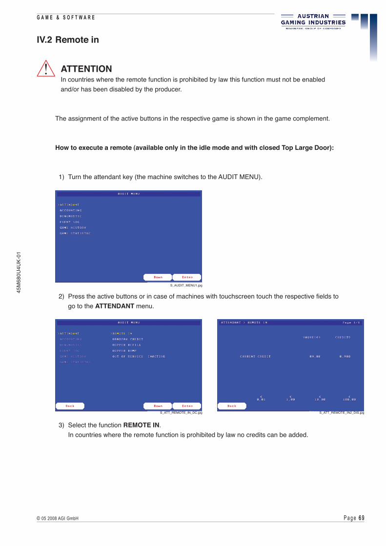
P a g e 6 9 6 9© 05 2008 AGI GmbH
G A M E & S O F T W A R E45
M68
0U4U
K-01
IV.2 Remote in
ATTENTIONIn countries where the remote function is prohibited by law this function must not be enabledand/or has been disabled by the producer.
The assignment of the active buttons in the respective game is shown in the game complement.
How to execute a remote (available only in the idle mode and with closed Top Large Door):
1) Turn the attendant key (the machine switches to the AUDIT MENU).
!
S_AUDIT_MENU1.jpg
2) Press the active buttons or in case of machines with touchscreen touch the respective fields to go to the ATTENDANT menu.
3) Select the function REMOTE IN. In countries where the remote function is prohibited by law no credits can be added.
S_ATT_REMOTE_IN_DC.jpg S_ATT_REMOTE_IN2_DIS.jpg

P a g e � 0 � 0 © 05 2008 AGI GmbH
G A M E & S O F T W A R E
45M
680U
4UK-
01
4) Press the respective buttons or in case of machines with touchscreen touch the respective fields to add credits.
5) The selected credit is registered automatically on the remote meter (or on the respective country-specific meter).
6) Release the attendant key.
7) The machine switches back to the game play mode.
The remote function can be used only if it has been enabled in the AUDIT MENU in MACHINE SETUP > PARAMETER SETTINGS ( see part IV.8 - AUDIT MENU).
S_ATT_REMOTE_IN1_DC.jpg S_ATT_REMOTE_IN2_DC.jpg

P a g e � 1 � 1© 05 2008 AGI GmbH
G A M E & S O F T W A R E45
M68
0U4U
K-01
IV.3 Handpay credit
ATTENTIONIn countries where the handpay function is prohibited by law this function must not be enabledand/or has been disabled by the producer.
The assignment of the active buttons in the respective game is shown in the game complement.
If a limit has been reached during a game, you can get to this page automatically by turning the attendant key.
How to execute a handpay (available only in the idle mode and with closed Top Large Door):
1) Turn the attendant key (the machine switches to the AUDIT MENU).
!
2) Press the active buttons or in case of machines with touchscreen touch the respective fields to go to the ATTENDANT menu.
S_AUDIT_MENU1.jpg
S_ATT_HANDPAY_CREDIT.jpg

P a g e � 2 � 2 © 05 2008 AGI GmbH
G A M E & S O F T W A R E
45M
680U
4UK-
01
3) Select the function HANDPAY CREDIT.
4) Press the respective buttons or in case of machines with a touchscreen touch the respective fields to handpay the current credit.
5) The handpaid credit is registered automatically on the handpay meter.
6) Release the attendant key.
7) The machine switches back to the game play mode.
The handpay function can only be used if it has been enabled in the AUDIT MENU inMACHINE SETUP > PARAMETER SETTINGS ( see part IV.8 - AUDIT MENU).
S_ATT_HANDPAY_CREDIT1_DC.jpg

P a g e � 3 � 3© 05 2008 AGI GmbH
G A M E & S O F T W A R E45
M68
0U4U
K-01
IV.4 Hopper refill
The assignment of the active buttons in the respective game is shown in the game complement.
To refill the hopper two options are available:
A) Refilling the hopper by using the coin slot: Refill the hopper by inserting the coins into the coin slot at closed Top Large Door. The refilled amount is registered automatically (no manual registration of the refilled amount required).
B) Filling coins directly into the hopper: The coins are refilled directly into the hopper at opened Top Large Door. After inserting the coins into the hopper the respective amount has to be entered manually using the function HOPPER REFILL.
Option A - Refilling the hopper by using the coin slot:
1) Turn the attendant key. The machine switches to the AUDIT MENU.
2) Press the active buttons or in case of machines with touchscreen touch the respective fields to go to the ATTENDANT menu.
3) Select the function HOPPER REFILL
S_AUDIT_MENU1.jpg
S_ATT_HOPPER_REFILL_DC.jpg

P a g e � 4 � 4 © 05 2008 AGI GmbH
G A M E & S O F T W A R E
45M
680U
4UK-
01
4) Insert the respective number of coins into the coin slot. The refilled amount is registered automatically. 5) Release the attendant key. 6) The machine switches back to the game play mode.
Option B - Filling coins directly into the hopper:
1) Open the Top Large Door and refill the respective number of coins into the hopper. 2) Turn the attendant key (the machine switches to the AUDIT MENU). 3) Press the active buttons or in case of machines with touchscreen touch the respective fields to
go to the ATTENDANT menu. 4) Select the function HOPPER REFILL.
S_ATT_HOPPER_REFILL1_DC.jpg
5) Use the touchscreen field “Select” or the active buttons to adjust, if coins should be added or substracted in steps of 1, 10 or 100 (“1 COIN”, “10 COINS”, “100 COINS” resp. “-1 COIN”, “-10 COINS” or “-100 COINS”).
6) Use the adjusted field (i.e. “100 COINS”) or the respective active button to adjust the refilled amount. The current selected amount is indicated at “Refill amount: X COINS”. This amount must exactly relate to the coins refilled, otherwise the accounting will be incorrect.
7) Press “REFILL” to finish the hopper refill procedure. The refilled amount is registered automatically and indicated at “HOPPER REFILL”.
8) Close the Top Large Door. 9) Release the attendant key. 10) The machine switches back to the game play mode.
S_AUDIT_MENU2.jpg S_ATT_HOPPER_REFILL1_DO.jpg

P a g e � 5 � 5© 05 2008 AGI GmbH
G A M E & S O F T W A R E45
M68
0U4U
K-01
IV.5 Hopper dump
ATTENTIONIn countries where the hopper dump function is prohibited by law, this function must not be enabledand/or has been disabled by the producer.
The assignment of the active buttons in the respective game is shown in the game complement.
How to dump the hopper (available only in the idle mode):
1) Open the Top Large Door.
2) Turn the attendant key (the machine switches to the AUDIT MENU).
!
3) Press the active buttons or in case of machines with touchscreen touch the respective fields to go to the ATTENDANT menu.
4) Select the function HOPPER DUMP.
S_AUDIT_MENU2.jpg
S_ATT_HOPPER_DUMP_DO.jpg

P a g e � 6 � 6 © 05 2008 AGI GmbH
G A M E & S O F T W A R E
45M
680U
4UK-
01
5) Press the active buttons or touch the respective fields to enter the sum of the amount to dump.
6) The refilled amount is registered automatically. This amount must exactly relate to the dumped coins, otherwise the accounting will be incorrect.
7) Close the Top Large Door.
8) Release the attendant key.
9) The machine switches back to the game play mode.
S_ATT_HOPPER_DUMP1_DO.jpg
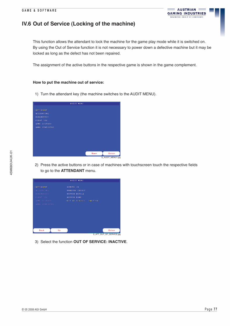
P a g e � � � �© 05 2008 AGI GmbH
G A M E & S O F T W A R E45
M68
0U4U
K-01
IV.6 Out of Service (Locking of the machine)
This function allows the attendant to lock the machine for the game play mode while it is switched on. By using the Out of Service function it is not necessary to power down a defective machine but it may be locked as long as the defect has not been repaired.
The assignment of the active buttons in the respective game is shown in the game complement.
How to put the machine out of service:
1) Turn the attendant key (the machine switches to the AUDIT MENU).
2) Press the active buttons or in case of machines with touchscreen touch the respective fields to go to the ATTENDANT menu.
3) Select the function OUT OF SERVICE: INACTIVE.
S_AUDIT_MENU1.jpg
S_ATT_OUT_OF_SERVICE.jpg

P a g e � 8 � 8 © 05 2008 AGI GmbH
G A M E & S O F T W A R E
45M
680U
4UK-
01
4) Press the active button or touch the field “Enter” to lock the machine.
5) Release the attendant key.
6) The machine switches back to the game play mode. On the screen a message is displayed containing the information, that the machine is out of service.
7) To unlock the machine, turn and release the attendant key. The machine is now enabled for gambling.
S_ATT_OUT_OF_SERVICE1.jpg
S_ATT_OUT_OF_SERVICE2.jpg

P a g e � 9 � 9© 05 2008 AGI GmbH
G A M E & S O F T W A R E45
M68
0U4U
K-01
IV.7 Top light
The top light indicates the different operational status (jackpot, error, service, etc.).
Novomatic Standard
Blue is on:
The SERVICE button has been pressed.
White is flashing fast:
The machine is in the idle mode and the Top Large Door or the Door-in-Door system is open.
The light is flashing until the fist game has been finished.
Blue is flashing slowly:
Error - the machine is not ready for play.
The error message is shown on the screen( see part IV.1 - Error handling).
Blue is flashing slowly, white is flashing fast:
Error - the machine is not ready for play.
The error message is indicated in case of error and the Top Large Dooror the Door-in-Door system is open.
Blue and white are flashing slowly:
Handpay is required.After the handpay has been finished the lamps stop flashing.

P a g e 8 0 8 0 © 05 2008 AGI GmbH
G A M E & S O F T W A R E
45M
680U
4UK-
01
Bally France
Green is flashing:
A limit has been reached.After the handpay has been finished the lamp stops flashing.
Red is on:
Error - the machine is not ready for play.
The error message is shown on the screen( see part IV.1 - Error handling).
Red is flashing:
The Top Large Door or the Door-in-Door system is open.
Yellow is flashing:
The SERVICE button has been pressed.

P a g e 8 1 8 1© 05 2008 AGI GmbH
G A M E & S O F T W A R E45
M68
0U4U
K-01
IV.8 Audit Menu
INFORMATIONDepending on machine configuration the items described in this part may vary.
INFORMATIONThe respective active buttons (illuminated) are located on the keyboard below the control panel shown on the screen. See game supplement.
IV.8.1 ATTENDANT Menu
Turn the attendant key to go the ATTENDANT menu. This menu shows the accounting and statistics, and several settings may be adjusted. The pages can be selected by pressing the active buttons or, in case of machines with touchscreen, by touching the respective fields.
The left illustration shows the AUDIT MENU indicated at closed Top Large Door, the right illustration shows the extended AUDIT MENU indicated at opened Top Large Door.
S_AUDIT_MENU1.jpg S_AUDIT_MENU2.jpg
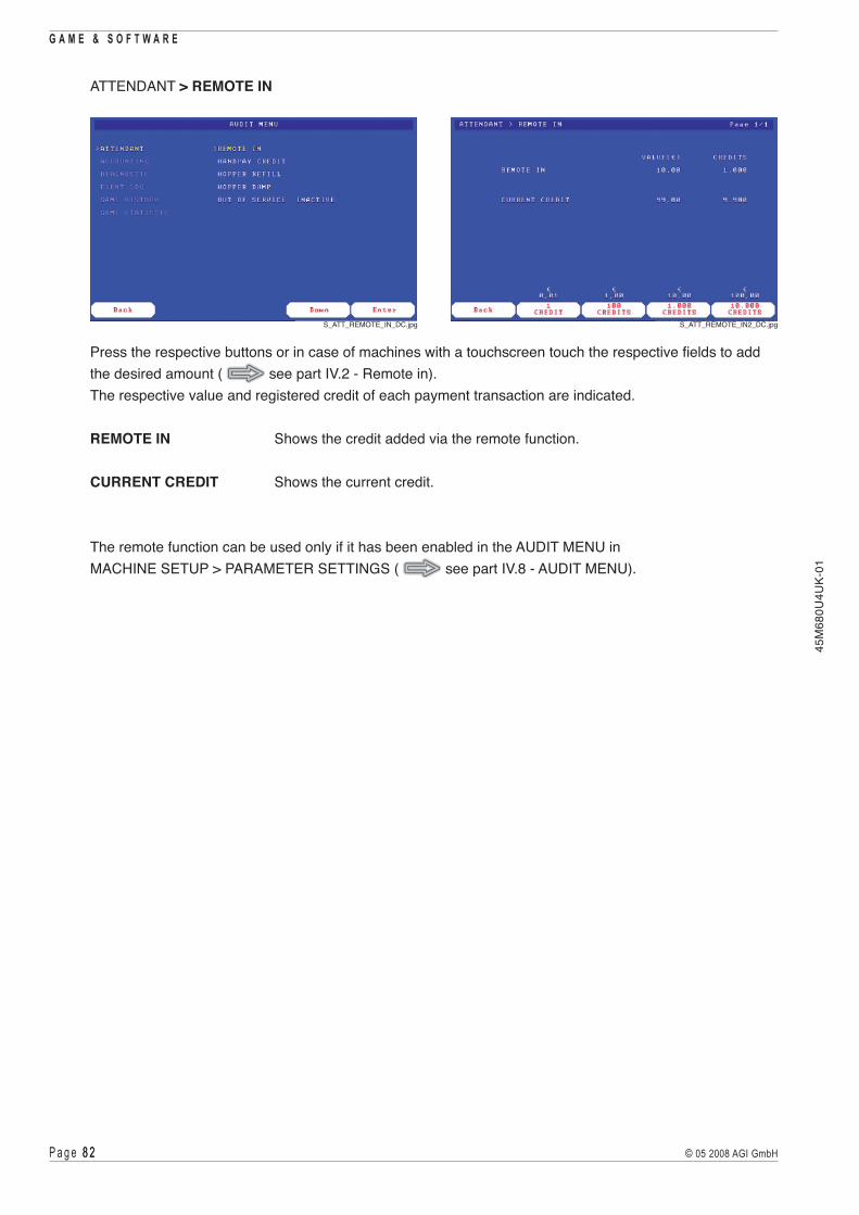
P a g e 8 2 8 2 © 05 2008 AGI GmbH
G A M E & S O F T W A R E
45M
680U
4UK-
01
ATTENDANT > REMOTE IN
Press the respective buttons or in case of machines with a touchscreen touch the respective fields to add the desired amount ( see part IV.2 - Remote in). The respective value and registered credit of each payment transaction are indicated.
REMOTE IN Shows the credit added via the remote function.
CURRENT CREDIT Shows the current credit.
The remote function can be used only if it has been enabled in the AUDIT MENU in MACHINE SETUP > PARAMETER SETTINGS ( see part IV.8 - AUDIT MENU).
S_ATT_REMOTE_IN_DC.jpg S_ATT_REMOTE_IN2_DC.jpg

P a g e 8 3 8 3© 05 2008 AGI GmbH
G A M E & S O F T W A R E45
M68
0U4U
K-01
ATTENDANT > HANDPAY CREDIT
CURRENT HANDPAY Press the respective buttons or in case of machines with a touchscreen touch the respective fields to handpay the current credit ( see part IV.3 - Handpay credit).
CASHABLE CREDIT Indicates the total amount of all cashable credits. FROM COIN Proportion of the cashable credit entered in coins. FROM BILL Proportion of the cashable credit entered in bills. FROM TICKET Proportion of the cashable credit entered in tickets. TICKET SEMIPROMOTIONAL Proportion of the cashable credit entered in promotional tickets. SEMIPROMOTIONAL Proportion of the cashable credit entered via online system. CASHABLE Proportion of the cashable credit which is not assignable to the
above mentioned credit types (e.g. remote). BANK Credit cashable from the bank display.
NONCASHABLE CREDIT Indicates the total amount of all non-cashable credits. Non-cashable credits have to be gambled away!
FROM TOKEN Proportion of the non-cashable credit entered in tokens. TICKET PROMOTIONAL Proportion of the non-cashable credit entered in promotional tickets. TICKET NONCASHABLE Proportion of the non-cashable credit entered in tickets. PROMOTIONAL Proportion of the non-cashable credit entered via online system. NONCASHABLE Proportion of the non-cashable credit which is not assignable to the
above mentioned credit types.
ATTENTIONFor each transaction, the monetary value and the corresponding credit amount are indicated. Which kind of credit is deemed “CASHABLE” or “NONCASHABLE” may vary depending on the jurisdiction.
S_ATT_HANDPAY_CREDIT.jpg S_ATT_HANDPAY_CREDIT1_DC.jpg
!

P a g e 8 4 8 4 © 05 2008 AGI GmbH
G A M E & S O F T W A R E
45M
680U
4UK-
01
ATTENDANT > HOPPER REFILL
TOTAL HOPPER LEVEL Total value of all coins available in the hopper.PERIODIC HOPPER LEVEL Total value of all coins available in the hopper for a certain period.REFILL LEVEL Indicates the defined hopper refill level.MISSING AMOUNT Coins still missing for the hopper refill level set.HOPPER REFILL Use the touchscreen field “Select” or the respective button to adjust, if coins should be added or substracted in steps of 1, 10 or 100 (“1 COIN”, “10 COINS”, “100 COINS” resp. “-1 COIN”, “-10 COINS”, “-100 COINS”). Use the adjusted field (i.e. “100 COINS”) or the respective button to adjust the refilled amount. The current selected amount is indicated at “Refill amount: X COINS”. Press “REFILL” to finish the hopper refill procedure ( see part IV.4 - Hopper refill). The number of coins, the respective value and the respective registered credit is now indicated at the menu item “HOPPER REFILL”. Turn/release the attendant key. Now the refilled number of coins, the respective value and the respective registered credit is indicated at the menu items “TOTAL HOPPER LEVEL” and “PERIODIC HOPPER LEVEL”.
The number of coins, the respective value and the respective registered credit of each payment transaction are indicated.
S_ATT_HOPPER_REFILL_DO.jpg S_ATT_HOPPER_REFILL1_DO.jpg

P a g e 8 5 8 5© 05 2008 AGI GmbH
G A M E & S O F T W A R E45
M68
0U4U
K-01
ATTENDANT > HOPPER DUMP
TOTAL HOPPER LEVEL Total value of all coins available in the hopper.PERIODIC HOPPER LEVEL Total value of all coins available in the hopper for a certain period.HOPPER DUMP Press the respective buttons or the respective touchscreen fields to enter the amount to dump the hopper ( see part IV.5 - Hopper dump).
The number of coins, the respective value and the respective registered credit of each payment transaction are indicated.
ATTENDANT > OUT OF SERVICE
This function allows the attendant to lock the machine for the game play mode while it is switched on ( see part IV.6 - Out of Service (Locking of the machine).
S_ATT_HOPPER_DUMP_DO.jpg S_ATT_HOPPER_DUMP1_DO.jpg
S_ATT_OUT_OF_SERVICE.jpg S_ATT_OUT_OF_SERVICE1.jpg
S_ATT_OUT_OF_SERVICE2.jpg

P a g e 8 6 8 6 © 05 2008 AGI GmbH
G A M E & S O F T W A R E
45M
680U
4UK-
01
IV.8.2 ACCOUNTING Menu
ACCOUNTING > MASTER ACCOUNTING
TOTAL IN Total value of all coins, tokens, tickets and bills inserted and credits added via the remote function.
COINS IN Total value of all coins inserted via the coin acceptor. TOKEN IN Total value of all tokens accepted. BILL IN Total value of all bills accepted. REMOTE IN Total value of all credits added via the remote function. CARD IN Total value of all credits inserted via cashless card. TICKET IN Total value of all credits inserted via ticket.
TOTAL OUT Total value of all credits paid out (hopper, handpay, card and vouchers). COINS OUT Total value of all coins paid out via the hopper. HANDPAY Total value of all amounts paid out via handpay function. CARD OUT Total value of credits added to the cashless card. TICKET OUT Total value of credits paid out via ticket printer. BILL OUT Total value of all bills paid out.
TOTAL IN-OUT Difference between TOTAL IN and TOTAL OUT.
The respective value and the respective registered credit of the payment transaction are indicated.
S_ACCOUNTING_MENU_DO.jpg
S_ACC_MASTER_ACCOUNTING_DO.jpg S_ACC_MASTER_ACC1.jpg

P a g e 8 � 8 �© 05 2008 AGI GmbH
G A M E & S O F T W A R E45
M68
0U4U
K-01
TOTAL MONEY TO DROP Total value of all coins and bills that can be removed. COINS TO DROP Total value of all coins that can be removed from the drop box. TOKENS TO DROP Total value of all tokens that can be removed. BILLS TO DROP Total value of all bills that can be removed from the stacker box.
TOTAL HOPPER LEVEL Total value of all coins available in the hopper. COINS TO HOPPER Total value of all coins diverted into the hopper via the coin acceptor. COINS OUT Total value of all coins paid out via the hopper. HOPPER REFILL Total value of all coins refilled directly to the hopper. HOPPER DUMP Total value of all coins paid out via the hopper with the
hopper dump function.
TOTAL DISPENSER LEVEL Total value of all bills available in the dispenser. BILLS TO DISPENSER Total value of all bills diverted into the dispenser via the bill acceptor. BILLS OUT Total value of all bills paid out via the dispenser. DISPENSER REFILL Total value of all bills refilled into the dispenser. DISPENSER DUMP Total value of all bills paid out via the dispenser with the
dispenser dump function.
TOTAL BET Total value of all bets.TOTAL WON Total value of all wins.
MACHINE YIELD Payout percentage.TOTAL GAMES Total number of all games played.TOTAL GAMES WON Total number of all games won.
The respective value and the respective registered credit of the payment transaction are indicated.
S_ACC_MASTER_ACC2.jpg S_ACC_MASTER_ACC3.jpg

P a g e 8 8 8 8 © 05 2008 AGI GmbH
G A M E & S O F T W A R E
45M
680U
4UK-
01
TICKET IN Total value of tickets accepted by the bill acceptor. CASHABLE Cashable tickets accepted by the bill acceptor. NONCASHABLE Non-cashable tickets accepted by the bill acceptor. PROMOTIONAL Promotional tickets accepted by the bill acceptor.
TICKET OUT Total value of tickets paid out via the ticket printer. CASHABLE Cashable tickets paid out via the ticket printer. NONCASHABLE Non-cashable tickets paid out via the ticket printer. PROMOTIONAL Promotional tickets paid out via the ticket printer.
Furthermore, the TOTAL NUMBER OF ACCEPTED TICKETS and the TOTAL NUMBER OF PRINTED TICKETS are indicated on this page.
The respective value and the respective registered credit of the payment transaction are indicated.
S_ACC_MASTER_ACC4.jpg

P a g e 8 9 8 9© 05 2008 AGI GmbH
G A M E & S O F T W A R E45
M68
0U4U
K-01
HANDPAY Total value of all handpays. CANCELLED CREDITS Total value of all credits cancelled via handpay function. WIN LIMIT JACKPOT Total value of all handpaid jackpot wins. PROGRESSIVE JACKPOT Total value of all handpaid external jackpots. MYSTERY JACKPOT Total value of all handpaid mystery jackpots.
TOTAL WIN Total value of all wins. WIN TO CREDIT Total value of all wins added to credit. JP WIN TO CREDIT Total value of all jackpot wins added to credit. WIN TO HANDPAY Total value of all handpaid wins. WIN TO CARD Total value of all wins transferred to the cashless card. WIN TO TICKET Total value of all wins paid out via ticket printer.
TOTAL BONUS Total value of the additional win option (bonusing system via network). DEDUCT. BONUS Tax-deductible part of the bonusing system. NON DEDUCT. BONUS Non-deductible part of the bonusing system. WAGER M. BONUS Wager according to bonusing system. AFT. CASHABLE BONUS Advanced Funds Transfer specific bonus. AFT. NONRESTR. BONUS Advanced Funds Transfer specific bonus.
The respective value and the respective registered credit of the payment transaction are indicated.
S_ACC_MASTER_ACC5.jpg

P a g e 9 0 9 0 © 05 2008 AGI GmbH
G A M E & S O F T W A R E
45M
680U
4UK-
01
CHANNEL Indicates the available bill channels.VALUE (€) Value of one bill of the respective bill channel.COUNT Total number of bills accepted on the respective bill channel.CREDIT Total number of credits inserted via the respective bill channel.TOTAL (€) Total value of all credits inserted via the respective bill channel.
CHANNEL Indicates the available coin channels.VALUE (€) Value of one coin of the respective coin channel.COUNT Total number of coins accepted via the respective coin channel.CREDIT Total number of credits inserted via the respective coin channel.TOTAL (€) Total value of credits inserted via the respective coin channel.
S_ACC_MASTER_ACC6.jpg
S_ACC_MASTER_ACC7.jpg

P a g e 9 1 9 1© 05 2008 AGI GmbH
G A M E & S O F T W A R E45
M68
0U4U
K-01
CHANNEL Indicates the available hopper channels.VALUE (€) Value of one coin of the respective hopper channel.COUNT Total number of coins accepted on the respective hopper channel.CREDIT Total number of credits inserted via the respective hopper channel.TOTAL (€) Total value of all credits inserted via the respective hopper channel.
COINS TO HOPPER Total amount of coins transported into the hopper.HOPPER REFILL Total amount of coins refilled into the hopper.HOPPER DUMP Total amount of coins removed from the hopper.HOPPER LEVEL Total value of all coins available in the hopper.
S_ACC_MASTER_ACC8.jpg

P a g e 9 2 9 2 © 05 2008 AGI GmbH
G A M E & S O F T W A R E
45M
680U
4UK-
01
ACCOUNTING > PERIODIC ACCOUNTING
PERIODIC IN Total value of all coins, tickets, tokens and bills inserted and credits added via the remote function for a certain period.
COINS IN Total value of all coins inserted via the coin acceptor for a certain period. TOKEN IN Total value of all tokens accepted for a certain period. BILL IN Total value of all bills accepted for a certain period. REMOTE IN Total value of all credits added via the remote function for a certain period. CARD IN Total value of all credits added via card for a certain period. TICKET IN Total value of all credits inserted via ticket for a certain period.
PERIODIC OUT Total value of all credits paid out for a certain period. COINS OUT Total value of all coins paid out via the hopper for a certain period. HANDPAY Total value of all credits paid out via the handpay function for a certain
period. CARD OUT Total value of all credits added to the cashless card for a certain period. TICKET OUT Total value of all credits paid out via ticket printer for a certain period. BILL OUT Total value of all bills paid out for a certain period.
PERIODIC IN-OUT Difference between TOTAL IN and TOTAL OUT for a certain period.
The respective value and the respective registered credit of each payment transaction are indicated.
S_ACC_PERIODIC_ACCOUNTING_DO.jpg S_ACC_PERIODIC_ACC1.jpg

P a g e 9 3 9 3© 05 2008 AGI GmbH
G A M E & S O F T W A R E45
M68
0U4U
K-01
PERIODIC MONEY TO DROP Total value of all coins and bills that can be removed for a certain period. COINS TO DROP Total value of all coins that can be removed from the drop box in a
certain period. TOKENS TO DROP Total value of all tokens that can be removed for a certain period. BILLS TO DROP Total value of all bills that can be removed from the stacker box in a
certain period.
PERIODIC HOPPER LEVEL Total value of all coins available in the hopper for a certain period. COINS TO HOPPER Total value of all coins diverted into the hopper via the coin acceptor in
a certain period. COINS OUT Total value of all coins paid out via the hopper for a certain period. HOPPER REFILL Total value of all coins refilled directly into the hopper for a certain
period. HOPPER DUMP Total value of all coins paid out via the hopper with the hopper dump
function for a certain period.
PERIODIC DISPENSER LEVEL Total value of all bills available in the dispenser for a certain period. BILLS TO DISPENSER Total value of all bills diverted into the dispenser via the bill acceptor for
a certain period. BILLS OUT Total value of all bills paid out via the dispenser for a certain period. DISPENSER REFILL Total value of all bills refilled into the dispenser for a certain period. DISPENSER DUMP Total value of all bills paid out via the dispenser with the
dispenser dump function for a certain period.
PERIODIC BET Total value of all bets for a certain period.PERIODIC WON Total value of all wins realised for a certain period.
MACHINE YIELD Payout percentage for a certain period.PERIODIC GAMES Total number of games played for a certain period.PERIODIC GAMES WON Total number of games won for a certain period.
The respective value and the respective registered credit of each payment transaction are indicated.
S_ACC_PERIODIC_ACC2.jpg S_ACC_PERIODIC_ACC3.jpg

P a g e 9 4 9 4 © 05 2008 AGI GmbH
G A M E & S O F T W A R E
45M
680U
4UK-
01
TICKET IN Total value of all tickets accepted for a certain period. CASHABLE Total value of cashable tickets accepted for a certain period. NONCASHABLE Total value of non-cashable tickets accepted for a certain period. PROMOTIONAL Total value of promotional tickets accepted for a certain period.
TICKET OUT Total value of all tickets paid out via the ticket printer for a certain period. CASHABLE Total value of cashable tickets paid out via the ticket printer for a certain
period. NONCASHABLE Total value of non-cashable tickets paid out via the ticket printer in a certain
period. PROMOTIONAL Total value of promotional tickets paid out via the ticket printer for a certain
period.
Furthermore, the TOTAL NUMBER OF ACCEPTED TICKETS for a certain period and the TOTAL NUMBER OF PRINTED TICKETS for a certain period are indicated on this page.
The respective value and the respective registered credit of the payment transaction are indicated.
S_ACC_PERIODIC_ACC4.jpg

P a g e 9 5 9 5© 05 2008 AGI GmbH
G A M E & S O F T W A R E45
M68
0U4U
K-01
HANDPAY Total value of all handpays for a certain period. CANCELLED CREDITS Total value of all credits cancelled via handpay function in a certain
period. WIN LIMIT JACKPOT Total value of all handpaid jackpot wins for a certain period. PROGRESSIVE JACKPOT Total value of all handpaid external jackpots for a certain period. MYSTERY JACKPOT Total value of all handpaid mystery jackpots for a certain period.
TOTAL WIN Total value of all wins for a certain period. WIN TO CREDIT Total value of all wins added to credit for a certain period. JP WIN TO CREDIT Total value of all jackpot wins added to credit for a certain period. WIN TO HANDPAY Total value of all handpaid wins for a certain period. WIN TO CARD Total value of all wins transferred to the cashless card in a certain
period. WIN TO TICKET Total value of all wins paid out via ticket printer for a certain period.
TOTAL BONUS Total value of the additional win option (bonusing system via network) in a certain period.
DEDUCT. BONUS Tax-deductible part of the bonusing system for a certain period. NON DEDUCT. BONUS Non-deductible part of the bonusing system for a certain period. WAGER M. BONUS Wager according to bonusing system for a certain period. AFT. CASHABLE BONUS Advanced Funds Transfer specific bonus. AFT. NONRESTR. BONUS Advanced Funds Transfer specific bonus.
The respective value and the respective registered credit of the payment transaction are indicated.
S_ACC_PERIODIC_ACC5.jpg

P a g e 9 6 9 6 © 05 2008 AGI GmbH
G A M E & S O F T W A R E
45M
680U
4UK-
01
CHANNEL Indicates the available bill channels.VALUE (€) Value of one bill of the respective bill channel.COUNT Total number of bills accepted via the respective bill channel for a certain period.CREDIT Total number of credits inserted via the respective bill channel for a certain period.TOTAL (€) Total value of credits inserted via the respective bill channel for a certain period.
CHANNEL Indicates the available coin channels.VALUE (€) Value of one coin of the respective coin channel.COUNT Total number of coins accepted via the respective coin channel for a certain period.CREDIT Total number of credits inserted via the respective coin channel for a certain period.TOTAL (€) Total value of credits inserted via the respective coin channel for a certain period.
S_ACC_PERIODIC_ACC6.jpg
S_ACC_PERIODIC_ACC7.jpg

P a g e 9 � 9 �© 05 2008 AGI GmbH
G A M E & S O F T W A R E45
M68
0U4U
K-01
CHANNEL Indicates the available hopper channels.VALUE (€) Value of one coin of the respective hopper channel.COUNT Total number of coins accepted via the respective hopper channel in a certain period.CREDIT Total number of credits inserted via the respective hopper channel in a certain period.TOTAL (€) Total value of credits inserted via the respective hopper channel in a certain period.
COINS TO HOPPER Total amount of coins transported into the hopper.HOPPER REFILL Total amount of coins refilled into the hopper.HOPPER DUMP Total amount of coins removed from the hopper.HOPPER LEVEL Total number of coins available in the hopper.
S_ACC_PERIODIC_ACC8.jpg

P a g e 9 8 9 8 © 05 2008 AGI GmbH
G A M E & S O F T W A R E
45M
680U
4UK-
01
ACCOUNTING > HARD METER COPY
The values represent the counter reading of the mechanical meters.Because of the variety of country-specific configurations the illustration shows the “Novomatic Standard” as an example.
BET Total value of all bets in credits.WIN Total value of all wins in credits.REMOTE Total value of all credits added via remote function.HANDPAY Total value of all credits paid out via handpay function.BILLS Total value of all bills inserted in credits.DROP Total value of all coins inserted into the drop box in credits.GAMES Total number of all games played.TOKEN Total value of all tokens inserted in credits.
ATTENTIONAfter a RAM Clear the parameters are “0” again!
S_ACC_HARD_METER_COPY_DO.jpg S_ACC_HARD_METER_COPY1.jpg
!
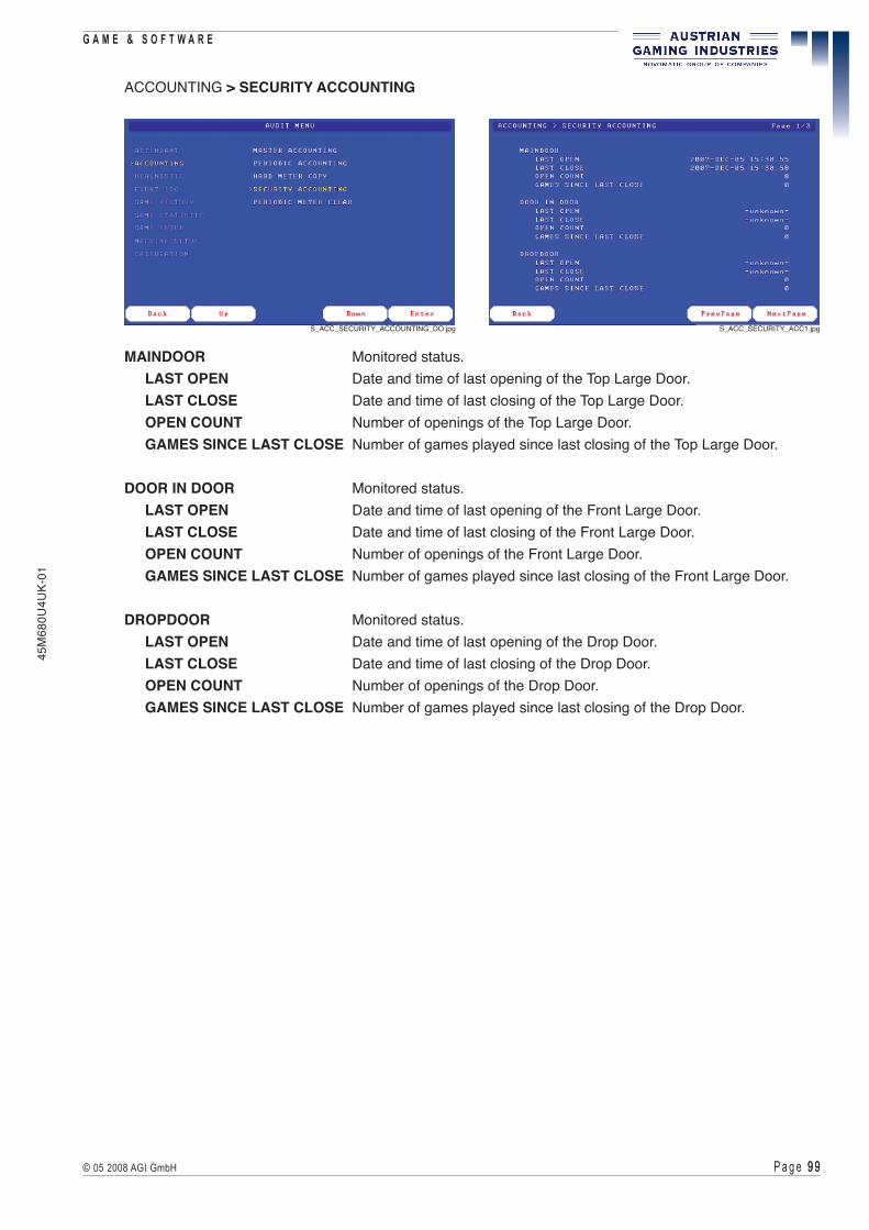
P a g e 9 9 9 9© 05 2008 AGI GmbH
G A M E & S O F T W A R E45
M68
0U4U
K-01
ACCOUNTING > SECURITY ACCOUNTING
MAINDOOR Monitored status. LAST OPEN Date and time of last opening of the Top Large Door. LAST CLOSE Date and time of last closing of the Top Large Door. OPEN COUNT Number of openings of the Top Large Door. GAMES SINCE LAST CLOSE Number of games played since last closing of the Top Large Door.
DOOR IN DOOR Monitored status. LAST OPEN Date and time of last opening of the Front Large Door. LAST CLOSE Date and time of last closing of the Front Large Door. OPEN COUNT Number of openings of the Front Large Door. GAMES SINCE LAST CLOSE Number of games played since last closing of the Front Large Door.
DROPDOOR Monitored status. LAST OPEN Date and time of last opening of the Drop Door. LAST CLOSE Date and time of last closing of the Drop Door. OPEN COUNT Number of openings of the Drop Door. GAMES SINCE LAST CLOSE Number of games played since last closing of the Drop Door.
S_ACC_SECURITY_ACCOUNTING_DO.jpg S_ACC_SECURITY_ACC1.jpg

P a g e 1 0 0 1 0 0 © 05 2008 AGI GmbH
G A M E & S O F T W A R E
45M
680U
4UK-
01
STACKERDOOR Monitored status. LAST OPEN Date and time of last opening of the Stacker Door. LAST CLOSE Date and time of last closing of the Stacker Door. OPEN COUNT Number of openings of the Stacker Door. GAMES SINCE LAST CLOSE Number of games played since last closing of the Stacker Door.
LOGIC AREA Monitored status. POWER ON AFTER OPEN Date and time of last opening of the Logic Door. OPEN COUNT Number of openings of the Logic Door. GAMES SINCE LAST CLOSE Number of games played since last closing of the Logic Door.
METER CONNECT Monitored status. LAST OPEN Date and time of last disconnection of the mechanical meters. LAST CLOSE Date and time of last connection of the mechanical meters. OPEN COUNT Number of disconnections of the mechanical meters. GAMES SINCE LAST CLOSE Number of games played since last connection of the
mechanical meters.
POWER FAIL Monitored status. LAST POWER FAIL Date and time of last power down. LAST POWER ON Date and time of last power on. POWER FAIL COUNT Number of power downs. DURING GAME PLAY Number of power downs during games played. GAMES SINCE LAST POWER FAIL Number of games played since last power down interruption.
S_ACC_SECURITY_ACC2.jpg S_ACC_SECURITY_ACC3.jpg

P a g e 1 0 1 1 0 1© 05 2008 AGI GmbH
G A M E & S O F T W A R E45
M68
0U4U
K-01
ACCOUNTING > PERIODIC METER CLEAR
PRESS CLEAR BUTTON TO CLEAR PERIODIC RAMPress the respective button or the respective touchscreen field to clear the periodic RAM.
S_ACC_PERIODIC_METER_CLEAR_DO.jpg S_ACC_PERIODIC_METER_CLEAR1.jpg

P a g e 1 0 2 1 0 2 © 05 2008 AGI GmbH
G A M E & S O F T W A R E
45M
680U
4UK-
01
IV.8.3 DIAGNOSTIC Menu
DIAGNOSTIC > PROGRAM VERSIONS
MACHINE NUMBER Indicates the configured machine number.MACHINE Indicates name, version and date of the complete machine software.EEPROM CONFIGURATION Indicates the EEPROM configuration.KERNEL Indicates version and date of the kernel.MAINBOARD VERSION Indicates the version of the mainboard.MAINBOARD SERIAL NUMBER Indicates the serial number of the mainboard.BACKPLANE VERSION Indicates the version of the backplane.PROGRAM ROM CRC Indicates the checksum of the program ROM.GAME SELECTOR Indicates the version of the game selector.GAME Indicates the name, version and date of the game.
S_DIAGNOSTIC_MENU_DO.jpg
S_DIA_PROGRAM_VERSIONS_DO.jpg S_DIA_PROGRAM_VERSIONS1.jpg

P a g e 1 0 3 1 0 3© 05 2008 AGI GmbH
G A M E & S O F T W A R E45
M68
0U4U
K-01
DIAGNOSTIC > DEVICE LISTING
Indicates the machine components which are recognized by the software.The number and the form of the entries depend on the current equipment of the machine (bill acceptor, ticket printer, etc.).
DIAGNOSTIC > MACHINE SELFTEST
Press Test button to start selftestPress the respective button or touch the respective touchscreen field to start the selftest.After the selftest is completed, a detailed listing of the tested devices is indicated.
S_DIA_DEVICE_LISTING_DO.jpg S_DIA_DEVICE_LISTING1.jpg
S_DIA_MACHINE_SELFTEST_DO.jpg S_DIA_MACHINE_SELFTEST1.jpg
S_DIA_MACHINE_SELFTEST3.jpg S_DIA_MACHINE_SELFTEST5.jpg

P a g e 1 0 4 1 0 4 © 05 2008 AGI GmbH
G A M E & S O F T W A R E
45M
680U
4UK-
01
DIAGNOSTIC > BUTTON AND LAMP TEST
BUTTON TEST The current status of the buttons (ON/OFF) is indicated.LAMP TEST All lamps are flashing steadily as long as this page is enabled.
To go back, press the buttons HOLD 1 and HOLD 2 simultaneously.Press the respective buttons to return to the DIAGNOSTIC menu.
DIAGNOSTIC > VIDEO TEST
Select the function VIDEO TEST to show the test chart on the screen.In case of eventual distortions or a defective colour reproduction the monitor can be readjusted according to this test chart.
S_DIA_BUTTON_AND_LAMP_TEST_DO.jpg S_DIA_BUTTON_AND_LAMP_TEST1.jpg
S_DIA_BUTTON_AND_LAMP_TEST4.jpg
S_DIA_VIDEO_TEST_DO.jpg S_DIA_VIDEO_TEST1.jpg

P a g e 1 0 5 1 0 5© 05 2008 AGI GmbH
G A M E & S O F T W A R E45
M68
0U4U
K-01
DIAGNOSTIC > AUDIO TEST
Press the respective buttons or touch the respective fields to start the audio test.
DIAGNOSTIC > TOUCH SCREEN TEST
Select the function TOUCH SCREEN TEST to check the calibration and functionality of the touchscreen. Touch the screen at different places. At each touch a point is enlightened on the screen.
S_DIA_AUDIO_TEST_DO.jpg S_DIA_AUDIO_TEST4.jpg
S_DIA_TOUCH_SCREEN_TEST_DO.jpg S_DIA_TOUCH_SCREEN_TEST1.jpg

P a g e 1 0 6 1 0 6 © 05 2008 AGI GmbH
G A M E & S O F T W A R E
45M
680U
4UK-
01
DIAGNOSTIC > HOPPER TEST
Select the function HOPPER TEST to check the functionality of the hopper. Follow the instructions indicated on the screen. Coins inserted are not registered!
DIAGNOSTIC > BILL ACCEPTOR TEST
S_DIA_HOPPER_TEST_DO.jpg S_DIA_HOPPER_TEST1.jpg
S_DIA_HOPPER_TEST2.jpg
S_DIA_BILL_ACC_TEST_DO.jpg S_DIA_BILL_ACC_TEST1.jpg
The BILL ACCEPTOR TEST function can be used to check the functionality of the bill acceptor.
ATTENTIONIf a bill is not detected, the reason may be that the insertion direction is not enabled in the menu itemMACHINE > BILL SETTINGS or the software is not programmed to accept the bill.
!
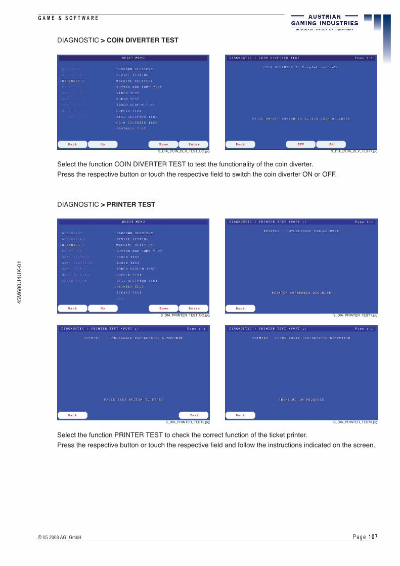
P a g e 1 0 � 1 0 �© 05 2008 AGI GmbH
G A M E & S O F T W A R E45
M68
0U4U
K-01
DIAGNOSTIC > COIN DIVERTER TEST
Select the function COIN DIVERTER TEST to test the functionality of the coin diverter.Press the respective button or touch the respective field to switch the coin diverter ON or OFF.
DIAGNOSTIC > PRINTER TEST
Select the function PRINTER TEST to check the correct function of the ticket printer.Press the respective button or touch the respective field and follow the instructions indicated on the screen.
S_DIA_COIN_DEV_TEST_DO.jpg S_DIA_COIN_DEV_TEST1.jpg
S_DIA_PRINTER_TEST_DO.jpg S_DIA_PRINTER_TEST1.jpg
S_DIA_PRINTER_TEST2.jpg S_DIA_PRINTER_TEST3.jpg

P a g e 1 0 8 1 0 8 © 05 2008 AGI GmbH
G A M E & S O F T W A R E
45M
680U
4UK-
01
DIAGNOSTIC > TICKET TEST
Select the function TICKET TEST to print a 0 credit ticket.
S_DIA_TICKET_TEST_DO.jpg S_DIA_TICKET_TEST1.jpg
S_DIA_TICKET_TEST2.jpg

P a g e 1 0 9 1 0 9© 05 2008 AGI GmbH
G A M E & S O F T W A R E45
M68
0U4U
K-01
Select the function NETWORK TEST to check the correct function of the selected network.
S_DIA_NETWORK_TEST_DO.jpg S_DIA_NETWORK_TEST1.jpg
DIAGNOSTIC > PAYTABLE TEST
The PAYTABLE TEST can be used to check the correct payout of the machine.Various winning situations can be simulated without prizes being paid out.
To start the paytable test the Top Large Door must be opened.Then activate the test and leave the AUDIT MENU.Now a game situation can be set by pressing the SERVICE button and the LINE buttons at the same time.The amount of bet may be selected and the simulation can be started when the START button is pressed.When the Top Large Door is closed again, the machine will return to the original game situation.
ATTENTIONWhen the ONE-SHOT PROGRESSIVE JACKPOT TEST is selected, a real jackpot is triggered at the external jackpot controller when the next game is started, provided that the respective winning combination was selected. The jackpot must then be set again. After a game, this setting will be deactivated automatically.
DIAGNOSTIC > NETWORK TEST
S_DIA_PAYTABLE_TEST_DO.jpg S_DIA_PAYTABLE_TEST1.jpg
!

P a g e 11 0 11 0 © 05 2008 AGI GmbH
G A M E & S O F T W A R E
45M
680U
4UK-
01
IV.8.4 EVENT LOG Menu
EVENT LOG > MACHINE EVENTS
All errors including date and time when they have occurred are listed.The error codes and error messages correspond to those listed in part IV.1.2.In case of an overflow the respective oldest entries are overwritten.
EVENT LOG > BILL ACCEPTOR EVENTS
All accepted bills including date and time of their insertion are listed.In case of an overflow the respective oldest entries are overwritten.
S_EVENT_LOG_MENU_DO.jpg
S_EVLOG_MACHINE_EV_DO.jpg S_EVLOG_MACHINE_EV1.jpg
S_EVLOG_BILL_ACC_EV_DO.jpg S_EVLOG_BILL_ACC_EV1.jpg

P a g e 111 111© 05 2008 AGI GmbH
G A M E & S O F T W A R E45
M68
0U4U
K-01
EVENTS > HANDPAY EVENTS
Lists all handpay events including date and time when they where paid out.In case of an overflow the respective oldest entries are overwritten.
EVENT LOG > CASHLESS CARD EVENTS
All accepted card credits including date and time are listed.In case of an overflow the respective oldest entries are overwritten.
EVENTS > JACKPOT EVENTS
Lists all external jackpots including date and time when they where hit.In case of an overflow the respective oldest entries are overwritten.
S_EVLOG_HANDPAY_EV_DO.jpg S_EVLOG_HANDPAY_EV1.jpg
S_EVLOG_CASHLESS_CARD_EV_DO.jpg S_EVLOG_CASHLESS_CARD_EV1.jpg
S_EVLOG_JACKPOT_EV_DO.jpg S_EVLOG_JACKPOT_EV1.jpg

P a g e 11 2 11 2 © 05 2008 AGI GmbH
G A M E & S O F T W A R E
45M
680U
4UK-
01
EVENT LOG > TICKET OUT
Lists all ticket events including validation number, value, ticket number, date and time.In case of an overflow the respective oldest entries are overwritten.
EVENTS > TICKET IN
Lists all ticket events including validation number, value, ticket number, date and time.In case of an overflow the respective oldest entries are overwritten.
S_EVLOG_TICKET_OUT_EV_DO.jpg S_EVLOG_TICKET_OUT_EV1.jpg
S_EVLOG_TICKET_IN_EV_DO.jpg S_EVLOG_TICKET_IN_EV1.jpg

P a g e 11 3 11 3© 05 2008 AGI GmbH
G A M E & S O F T W A R E45
M68
0U4U
K-01
IV.8.5 GAME HISTORY Menu
GAME HISTORY > Selected Game
GAME HISTORY Game history of the selected game.Game Current number of the game at a certain time.Phase Phase during the indicated game (1st deal is phase 1, 2nd deal is phase 2, etc.), depending on the indicated game.
Date Indicates the date of the game.Time Indicates the time of the game.
Cred. bef. Amount of credit before the game was started.Bet Bets placed in credits.Bet mult. Multidenomination bets placed in credits.Win Wins in credits.
Gambles Number of times gambled.Gamble in Value of wins which has been gambled.Gamble out Value of wins which has been paid out after gamble.
SINCE LAST GAMETokens in Total value of tokens inserted since last game.Coins in Total value of coins inserted since last game.Bills in Total value of bills inserted since last game.Remote in Total value of all credits added via the remote function since last game.Card in Total value of all credits added via card since last game.Bonus in Total value of all credits added via online system since last game.Ticket in Total value of all credits inserted via tickets since last game.Collected Total value of all credits paid out via the hopper and the handpay function since last game.
S_GAME_HISTORY_MENU_DO.jpg S_GAME_HISTORY_MENU1.jpg

P a g e 11 4 11 4 © 05 2008 AGI GmbH
G A M E & S O F T W A R E
45M
680U
4UK-
01
IV.8.6 GAME STATISTIC Menu
GAME STATISTIC > Selected Game
The game statistics depend on the selected game. If different bets (BET) are permitted in the game, the first page always indicates the total statistic (BET - independent) and each BET available is represented separately (e.g. page 2 = BET 1, page 3 = BET 2, etc.).
S_GAME_STATISTIC_MENU_DO.jpg S_GAME_STAT_SEL_GAME_DO.jpg
S_GAME_STAT_SEL_GAME1.jpg

P a g e 11 5 11 5© 05 2008 AGI GmbH
G A M E & S O F T W A R E45
M68
0U4U
K-01
IV.8.7 GAME SETUP Menu
GAME SETUP > Selected Game
On this page several functions specific to the selected game can be featured.
S_GAME_SETUP_MENU.jpg
S_GAME_SETUP_SEL_GAME.jpg S_GAME_SETUP_SEL_GAME1.jpg

P a g e 11 6 11 6 © 05 2008 AGI GmbH
G A M E & S O F T W A R E
45M
680U
4UK-
01
IV.8.8 MACHINE SETUP Menu
MACHINE SETUP > LIMIT SETUP
INFORMATIONIn comparison to the CREDIT LIMIT the CREDIT IN LIMIT must always be lower by AT LEAST the value representedbythehighestconfigurationbill(coin,token).This ensures that by insertion of a bill (coin, token) only the CREDIT IN LIMIT may be reached and never the CREDIT LIMIT.
CREDIT IN LIMIT If the limit has been reached, no more credits can be added (coin and bill acceptor are blocked), also the remote function is disabled.
0... No CREDIT IN LIMIT.
CREDIT LIMIT Maximum credit value that may be reached in the game. If the limit has been reached, a handpay is required.
0... No CREDIT LIMIT.
JACKPOT LIMIT Maximum value of win paid out by the machine (added to credit or paid out via the hopper).
0... No JACKPOT LIMIT.
CELEBRATION LIMIT Available only in cashless card systems. If this limit is reached (under jackpot limit), a handpay to the cashless card has to be performed.
S_MACHINE_SETUP_MENU.jpg
S_MACH_SETUP_LIMIT_SET.jpg S_MACH_SETUP_LIMIT_SET1.jpg

P a g e 11 � 11 �© 05 2008 AGI GmbH
G A M E & S O F T W A R E45
M68
0U4U
K-01
DOUBLE UP LIMIT Maximum credit value that may be reached in the double-up game.
HOPPER PAYOUT LIMIT Maximum number of coins that can be paid out via the hopper, if the CASH button has been pressed or in case of wins. All amounts in excess have to be paid out via the handpay function.
0... No HOPPER LIMIT.
TICKET PAYOUT LIMIT Maximum amount that can be paid out via the ticket printer. All amounts in excess have to be paid out via the handpay function.
0... No TICKET LIMIT.
COINS IN LIMIT Indicates the number of coins that can be inserted without a game played.
0... No COIN IN LIMIT.
MINIMUM HANDPAY Minimum amount of win paid out via handpay.
EVEN HANDPAY Indicates the rounding factor for handpay. For example: if 50 is set, 1750 are paid instead of 1755, the remaining 5 continue on the credit.
Press the corresponding buttons or touch the respective fields to perform the desired settings.In each case a MIN and a MAX value are indicated in the range of which the current value can be set.Due to regulation some value ranges may be limited or the possibility of setting may be prohibited in general.

P a g e 11 8 11 8 © 05 2008 AGI GmbH
G A M E & S O F T W A R E
45M
680U
4UK-
01
MACHINE SETUP > PARAMETER SETUP
Press the corresponding buttons or touch the respective fields to perform the desired settings.
INFORMATIONDependingonthegameconfigurationandthegamesomeofthefollowingfunctionslistedbelowmaynot be available!
START MODE Determines the required player interactions to start a new game if credits are available.
0 ... RE-BET AT START A game is started with the last bet if the START button is pressed.
1 ... BET AND START To start each game first a bet must always be selected, then the start button has to be pressed. This parameter relates only to machines with physical reels. For all other machines (video, poker, roulette, ...) a game is started with the last bet if the START button is pressed as for START MODE 0.
2 ... AUTOSTART A game is started with the last bet if the START button is pressed. If the AUTOSTART button is pressed, a series of games is started automatically with the last bet.
REMOTE INPUT Enables/disables the remote function.0... DISABLED The remote function is disabled.1... ENABLED The remote function is enabled.
HANDPAY CREDIT Enables/disables the handpay function.0... DISABLED The handpay function is disabled.1... ENABLED The handpay function is enabled.
S_MACH_SETUP_PARAMETER_SET.jpg S_MACH_SETUP_PARAMETER_SET1.jpg
P a g e 11 9 11 9© 05 2008 AGI GmbH
G A M E & S O F T W A R E45
M68
0U4U
K-01
BILL INPUT Determines the way inserted bills are handled.0 ... TO HOPPER Bills are changed. The highest bill must be lower than the
hopper limit.1 ... TO CREDIT The value of inserted bills is added to the credit.2 ... TO CREDIT/COMPULSORY GAME Bills inserted are added to the credit and a compulsory game
must be played before the credit can be paid out.3 ... TO CREDIT/PLAY 50% Bills inserted are added to the credit.
A minimum of 50 % of the value of each inserted bill must be played before the system accepts a new bill.
COIN INPUT Determines the coin accounting.0... TO BET Coins are registered on the CREDITS PLAYED meter until the maximum bet is reached. A game is not started automatically unless the MAX BET button is pressed.1... TO BET/START Coins are registered on the CREDITS PLAYED meter until the maximum bet is reached. The game starts automatically.2... TO BET/TO CREDIT Coins are registered on the CREDITS PLAYED meter until the maximum bet is reached - any subsequent coins are registered on the CREDIT meter. A game is not started automatically unless the MAX BET button is pressed.3... TO CREDIT Coins are registered on the CREDIT meter. A game is not started automatically unless the MAX BET button is pressed and enough credits are available.4... TO CREDIT/CANCEL Coins are registered on the CREDIT meter. No game can be started with the MAX BET button.
WIN OUTPUT Determines the accounting of the wins.0... TO HOPPER All wins are paid out via the hopper.1... TO CREDIT All wins are registered on the CREDIT meter.
PAY AT JACKPOT LIMIT Determines the way jackpots are handled.0... WIN Only the win is paid.1... WIN + CREDIT The win and the credit is paid.
PAY AT CREDIT LIMIT Determines the way the credit limit is handled.0... WIN Only the win is paid.1... WIN + CREDIT The win and the credit is paid.
PARTIAL PAY MODE Determines whether a partial payout can be made.0... NO PARTIAL HANDPAY Partial payouts cannot be made. The entire amount must be handpaid.1... PARTIAL HANDPAY System allows partial payout. The hopper pays coins until the hopper limit is reached, the remaining amount must be handpaid.

P a g e 1 2 0 1 2 0 © 05 2008 AGI GmbH
G A M E & S O F T W A R E
45M
680U
4UK-
01
HOPPER DUMP Enables/disables the hopper dump function.0... DISABLED Hopper dump is disabled.1... ENABLED Hopper dump is enabled.
HOPPER STRATEGY Determines the way payout is handled when two hoppers are used.0... HIGH VALUE + RETRY If the first hopper is already empty, the machine switches over to the second hopper for payout.1... HIGH VALUE High-value coins are preferred for payout, the remaining amount is paid out in lower-value coins.2... BALANCED Wins are paid out with a balanced number of both high-value and low-value coins.
WINCOUNTER SPEED Determines the win counting speed.0... SLOW Win counting is slow.1... FAST Win counting is fast.
BILL ACCEPTOR SECURITY Activates/deactivates disabling of the bill acceptor after insertion of a bill failed.0... OFF The bill acceptor is never disabled.1... 10 REJECTED The bill acceptor is disabled after 10 attempts failed.2... 5 REJECTED The bill acceptor is disabled after 5 attempts failed.
S_MACH_SETUP_PARAMETER_SET2.jpg
HOPPER REMAINDER Determines the way that non-cashable credits are handled.0... TO CREDIT Remaining amounts remain on the CREDIT meter.1... TO HANDPAY Remaining amounts must be handpaid.2... CREDIT + HANDPAY Remaining amounts remain on the CREDIT meter. After pressing the CASH button a handpay of the remaining amount is offered.
SYSTEM LANGUAGE Setting of the system language.0... ENGLISH 4... FRENCH1... GERMAN 5... NORWEGIAN2... SPANISH 6... HUNGARIAN3... PORTUGUESE

P a g e 1 2 1 1 2 1© 05 2008 AGI GmbH
G A M E & S O F T W A R E45
M68
0U4U
K-01
MACHINE SETUP > GAME LANGUAGE SETUP
Press the corresponding buttons or touch the respective fields to set the desired game language.
MACHINE SETUP > BILL/COIN ACCEPTOR SETUP
BILL ACCEPTOR X Indicates the bill acceptor to which the settings correspond.CHANNEL Bill channels available.VALUE Monetary value of the bills accepted via the respective bill channel.ENABLE Enables/disables the bill channel.DIRECTION Bills are accepted only if they are inserted in a certain direction
(depends on the used bill acceptor).
S_MACH_SETUP_GAME_LANG_SET.jpg S_MACH_SETUP_GAME_LANG_SET1.jpg
S_MACH_SETUP_BCACC_SET.jpg S_MACH_SETUP_BCACC_SET1.jpg
Euro11.eps Euro22.eps

P a g e 1 2 2 1 2 2 © 05 2008 AGI GmbH
G A M E & S O F T W A R E
45M
680U
4UK-
01
COIN ACCEPTOR X Indicates the coin acceptor to which the settings correspond.CHANNEL Coin channels available.VALUE Monetary value of the coins accepted via the respective channel.ENABLE Enables/disables the coin channel.
This page indicates the basic settings of coin paths, if the machine is equipped with more than one coin acceptor incl. respective hopper. The settings are done via DIP switches on the USB devices belonging to the coin acceptors and hoppers (before a RAM Clear!) ( see part V - Coin acceptor or Hopper).
PATH Number of the coin path.COIN Indicates the value of the coin inserted via the coin acceptor assigned to this coin path.HOPPER Indicates the value of the coin inserted into the hopper assigned to this coin path.CASHBOX Indicates the respective cashbox, to which all coins are entered via this coin path. If the machine is equipped with only one cashbox, it used for all coin paths and is indicated with 1.
S_MACH_SETUP_BCACC_SET2.jpg
S_MACH_SETUP_BCACC_SET3.jpg
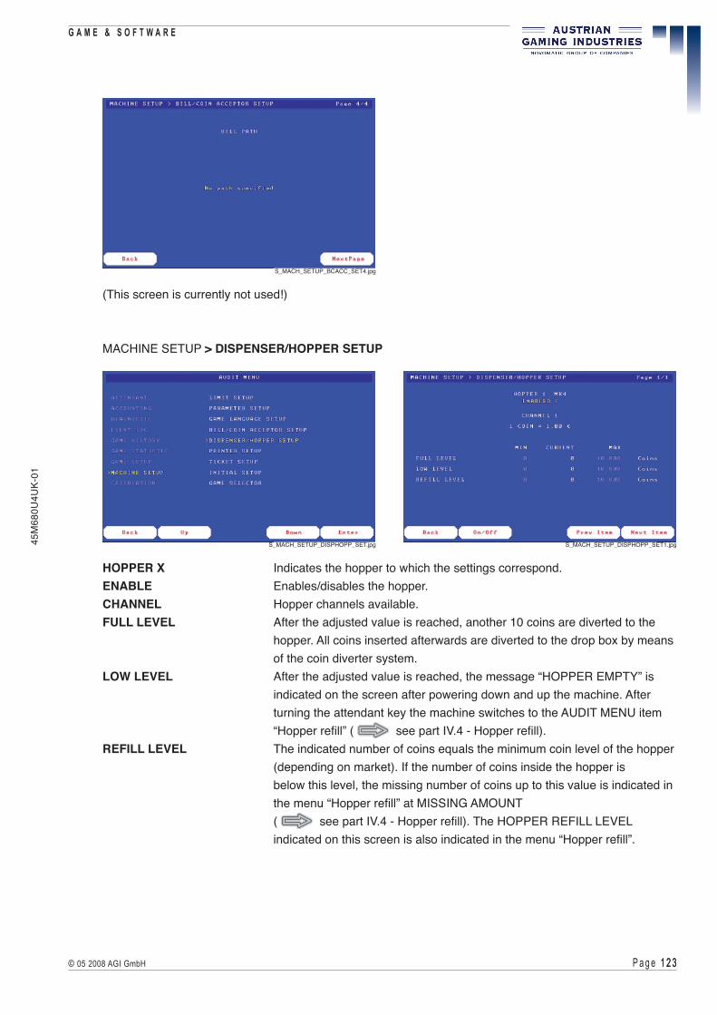
P a g e 1 2 3 1 2 3© 05 2008 AGI GmbH
G A M E & S O F T W A R E45
M68
0U4U
K-01
(This screen is currently not used!)
MACHINE SETUP > DISPENSER/HOPPER SETUP
HOPPER X Indicates the hopper to which the settings correspond.ENABLE Enables/disables the hopper.CHANNEL Hopper channels available.FULL LEVEL After the adjusted value is reached, another 10 coins are diverted to the hopper. All coins inserted afterwards are diverted to the drop box by means of the coin diverter system.LOW LEVEL After the adjusted value is reached, the message “HOPPER EMPTY” is indicated on the screen after powering down and up the machine. After turning the attendant key the machine switches to the AUDIT MENU item “Hopper refill” ( see part IV.4 - Hopper refill).REFILL LEVEL The indicated number of coins equals the minimum coin level of the hopper (depending on market). If the number of coins inside the hopper is below this level, the missing number of coins up to this value is indicated in the menu “Hopper refill” at MISSING AMOUNT ( see part IV.4 - Hopper refill). The HOPPER REFILL LEVEL indicated on this screen is also indicated in the menu “Hopper refill”.
S_MACH_SETUP_BCACC_SET4.jpg
S_MACH_SETUP_DISPHOPP_SET.jpg S_MACH_SETUP_DISPHOPP_SET1.jpg

P a g e 1 2 4 1 2 4 © 05 2008 AGI GmbH
G A M E & S O F T W A R E
45M
680U
4UK-
01
MACHINE SETUP > PRINTER SETUP
PRINTER X Indicates the printer to which the settings correspond.PRINTER INTENSITY Indicates the line intensity for ticket printout.PAPER CUT METHOD Indicates the cut method for ticket printout.ENABLE Enables/disables the ticket printer.
Before you remove the ticket printer from the machine (e.g. for maintenance or repair), you have to disable it on this page. Otherwise the removal of the ticket printer could cause error messages!
MACHINE SETUP > TICKET SETUP
This page indicates the currently selected network protocol used for payout via the ticket printer (e.g. TICKET: GSP TICKET). The utilisation of a ticket printer is only supported by IGT and GSP(see MACHINE SETUP > INITIAL SETUP, features TICKET OUT and TICKET IN).
All settings indicated on this page are dependent on market. Some settings are preset by the manufacturer.Those default settings cannot be modified.
TICKET INFO: Default settings; no selections can be made.BAR CODE TYPETYPE OF VALIDATIONTICKET COPY
S_MACH_SETUP_PRINTER_SET.jpg S_MACH_SETUP_PRINTER_SET1.jpg
S_MACH_SETUP_TICKET_SET.jpg S_MACH_SETUP_TICKET_SET1.jpg
P a g e 1 2 5 1 2 5© 05 2008 AGI GmbH
G A M E & S O F T W A R E45
M68
0U4U
K-01
TICKET IN Enables/disables ticket accepting via the bill acceptor.
DIFFERENT CREDIT TYPES The following functions are selectable:PRINT ALL Enables printout of cashable and non-cashable (promotional) tickets.DON’T PRINT As long as there are non-cashable credits present, no tickets are printed. The non-cashable credits have to be gambled away first.
CHANGE TICKET For a situation where the ticket amount does not match the denomination of the machine (e.g. 1 credit = € 1,00), the following ways of handling can be adjusted:REJECT If a ticket with an amount of € 10,50 is inserted and the denomination of the machine is € 1,00 the ticket will be rejected at once.PRINT EXCHANGE AT ONCE If a ticket with an amount of € 10,50 is inserted and the denomination of the machine is € 1,00 the ticket will be accepted, and € 10,00 will be added to the CREDIT meter. Then the machine automatically validates and prints out a ticket worth € 0,50 (= exchange ticket).PRINT ALL AT CASHOUT If a ticket with an amount of € 10,50 is inserted and the denomination of the machine is € 1,00 the ticket will be accepted, and € 10,00 will be added to the CREDIT meter. The remaining amount of € 0,50 will be stored internally and included at the cashout later on.
TICKET LAYOUT The ticket layout is pre-selected (Layout 5 = DEFAULT). This layout is also supported by the bill acceptors WBA25 and Cashflow. The ticket layouts 1, 2, 3 and 4 are older layouts, layout 6 is similar to layout 5, only the barcode width is different.
TICKET LANGUAGE SOURCE Here you can select, in which language the ticket should be printed.MACHINE If this feature is enabled, the tickets are printed in the same language as adjusted in the basic settings of the machine (system language).PRINTER For special languages like Russian the printer can be loaded with a special firmware to print tickets in the desired language (see part V - Ticket printer).
DATE FORMAT The required date format, which will be printed on the ticket, can be selected.
HANDPAY RECEIPT If this function is enabled, a handpay receipt is printed out automatically every time a handpay is performed.
TICKET OUT Enables/disables the printout of tickets. If this function is disabled, no tickets can printed, even though the printer is enabled in the menu MACHINE > PRINTER SETUP.

P a g e 1 2 6 1 2 6 © 05 2008 AGI GmbH
G A M E & S O F T W A R E
45M
680U
4UK-
01
MACHINE SETUP > INITIAL SETUP
This menu indicates the current basic settings.
To change the basic settings first perform a RAM Clear ( see part IV.9 - RAM Clear). Then press the corresponding buttons or touchscreen areas to select the desired settings.
DENOMINATION Indicates the defined accounting value.CURRENCY Indicates the defined currency.MAIN COIN Indicates the denomination of the main coin (coin acceptor 1/first channel).TOKENISATION Indicates the number of credits per coin (=tokenisation).
MAXIMUM BET Indicates the maximum bet per game.MAXIMUM BET PER ROW Indicates the maximum bet per payline.LA WIN LIMIT Indicates the defined LA win limit (LA = Legislation Authority). The machine will lock if this limit is exceeded.GAME WIN LIMIT Indicates the maximum win defined.ALARM SOUND Indicates when the alarm sound is activated.MACHINE NUMBER Indicates the configured machine number.ASSET NUMBER Indicates the configured asset number. This number is depending on the installed IGT network.
S_MACH_SETUP_INITIAL_SET.jpg S_MACH_SETUP_INITIAL_SET01_12.jpg

P a g e 1 2 � 1 2 �© 05 2008 AGI GmbH
G A M E & S O F T W A R E45
M68
0U4U
K-01
This page indicates the currently adjusted settings for the current date and time.
UTC “Universal Time Co-ordinated” (world time) Default settings, no selections possible.
LOCAL TIME Indicates the current local time, which is the time used in the machine log files.
TIME ZONE This menu item can be used to set the local time. Usually the local time differs from UTC in steps of clock hours (UTC +/- 1 to 12 hours). In some countries the local time may differ from UTC in other steps. In this case the local time has to be set manually at the menu item LOCAL TIME.
SUMMERTIME This menu item is used to set the beginning and the end of the country-specific summertime. The settings can be user-defined, or you can select on of the default rules (country-specific). The beginning and the end dates of the summertime settings in accordance with the selected default rule are indicated under SUMMERTIME STARTS and SUMMERTIME ENDS below. At the end of the period set for summertime the machine will switch back to the local time automatically.
RULE 00 (no summertime): for countries without summertime RULE 01 (user defined): manual adjustment of the summertime RULE 02 (EU): default summertime settings for several countries of the EU RULE 03 (USA, CAN): default summertime settings for Canada and several states of the USA RULE 04 (USA 07): default summertime settings for several states of the USA RULE 05 (RU): default summertime settings for Russia RULE 06 (AUS): default summertime settings for Australia
SUMMERTIME STARTS: Indicates the date and the time of the beginning of the summertime. This menu item can be used for manual selection of date and time of the beginning of the local summertime.
SUMMERTIME ENDS: Indicates the date and the time of the end of the summertime. This menu item can be used for manual selection of date and time of the end of the local summertime.
S_MACH_SETUP_INITIAL_SET02_12.jpg
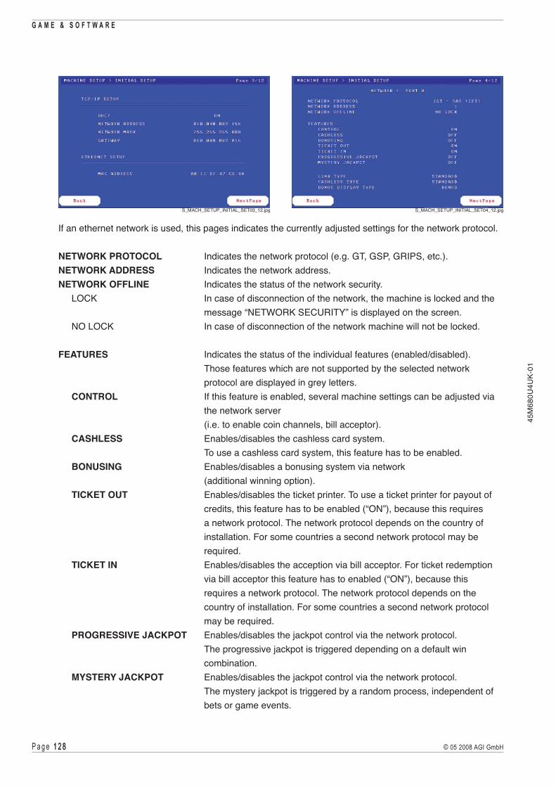
P a g e 1 2 8 1 2 8 © 05 2008 AGI GmbH
G A M E & S O F T W A R E
45M
680U
4UK-
01
If an ethernet network is used, this pages indicates the currently adjusted settings for the network protocol.
NETWORK PROTOCOL Indicates the network protocol (e.g. GT, GSP, GRIPS, etc.).NETWORK ADDRESS Indicates the network address.NETWORK OFFLINE Indicates the status of the network security. LOCK In case of disconnection of the network, the machine is locked and the
message “NETWORK SECURITY” is displayed on the screen. NO LOCK In case of disconnection of the network machine will not be locked.
FEATURES Indicates the status of the individual features (enabled/disabled). Those features which are not supported by the selected network protocol are displayed in grey letters.
CONTROL If this feature is enabled, several machine settings can be adjusted via the network server (i.e. to enable coin channels, bill acceptor).
CASHLESS Enables/disables the cashless card system. To use a cashless card system, this feature has to be enabled.
BONUSING Enables/disables a bonusing system via network (additional winning option).
TICKET OUT Enables/disables the ticket printer. To use a ticket printer for payout of credits, this feature has to be enabled (“ON”), because this requires a network protocol. The network protocol depends on the country of installation. For some countries a second network protocol may be required.
TICKET IN Enables/disables the acception via bill acceptor. For ticket redemption via bill acceptor this feature has to enabled (“ON”), because this requires a network protocol. The network protocol depends on the country of installation. For some countries a second network protocol may be required.
PROGRESSIVE JACKPOT Enables/disables the jackpot control via the network protocol. The progressive jackpot is triggered depending on a default win combination.
MYSTERY JACKPOT Enables/disables the jackpot control via the network protocol. The mystery jackpot is triggered by a random process, independent of bets or game events.
S_MACH_SETUP_INITIAL_SET03_12.jpg S_MACH_SETUP_INITIAL_SET04_12.jpg

P a g e 1 2 9 1 2 9© 05 2008 AGI GmbH
G A M E & S O F T W A R E45
M68
0U4U
K-01
LINK TYPE Indicates the type of network connection (e.g. Standard, Fibre Optics). CASHLESS TYPE Indicates the type of cashless system (e.g. Standard). BONUS DISPLAY TYPE Indicates the type of displaying the bonus.
JACKPOT PROTOCOL Indicates the type of the selected jackpot protocol. JACKPOT ADDRESS Indicates the jackpot address. PROGRESSIVE GAME Indicates the name of the progressive jackpot. SHOW WIN Indicates the conversion factor for the jackpot display. JACKPOT LEVEL X Indicates the configuration of the jackpot levels.
S_MACH_SETUP_INITIAL_SET05_12.jpg

P a g e 1 3 0 1 3 0 © 05 2008 AGI GmbH
G A M E & S O F T W A R E
45M
680U
4UK-
01
PROGRESSIVE JACKPOT LEVELMYSTERY JACKPOT LEVEL Indicates the active jackpot type.
DISPLAYED JACKPOT Indicates the amount as shown on the jackpot display. BASE VALUE Indicates the amount at which the jackpot starts. CURRENT VALUE Indicates the current amount of the jackpot. INCREMENT LIMIT When this limit is reached, the jackpot is hit. INCREMENT 1 Indicates the steps by which the jackpot is increased. INCREMENT 2 Indicates the steps by which the jackpot is increased when
it is close to the increment limit. MYSTERY LIMIT When this limit is reached, the jackpot is hit. INCREMENT Indicates the steps by which the jackpot is increased.
HIDDEN JACKPOT This jackpot runs in the background during the active jackpot. After the active jackpot is hit, the hidden jackpot becomes operative as active jackpot (the value of the hidden jackpot is added to the base value).
BASE VALUE Indicates the amount at which the jackpot starts. CURRENT VALUE Indicates the current amount of the jackpot. INCREMENT LIMIT When this limit is reached, the jackpot is hit. INCREMENT 1 Indicates the steps by which the jackpot is increased. INCREMENT 2 Indicates the steps by which the jackpot is increased when
it is close to the increment limit. INCREMENT Indicates the steps by which the jackpot is increased.
S_MACH_SETUP_INITIAL_SET06_12.jpg S_MACH_SETUP_INITIAL_SET07_12.jpg

P a g e 1 3 1 1 3 1© 05 2008 AGI GmbH
G A M E & S O F T W A R E45
M68
0U4U
K-01
DENOMINATION Indicates the fixed accounting value.COIN ACCEPTOR X Indicates the number and type of the selected coin acceptor.CHANNEL Coin channels available.COIN Definition of the coins accepted via the respective channel.TOKENISATION Indicates the number of credits per coin.
DENOMINATION Indicates the fixed accounting value.BILL ACCEPTOR X Indicates the number and type of the selected bill acceptor.CHANNEL Bill channels available.BILL Definition of the bills accepted via the respective channel.TOKENISATION Indicates the number of credits per bill.
S_MACH_SETUP_INITIAL_SET08_12.jpg
S_MACH_SETUP_INITIAL_SET09_12.jpg

P a g e 1 3 2 1 3 2 © 05 2008 AGI GmbH
G A M E & S O F T W A R E
45M
680U
4UK-
01
DENOMINATION Indicates the fixed accounting value.HOPPER X Indicates the number and type of the selected hopper.CHANNEL Coin channels available.COIN Definition of the coins accepted via the respective channel.TOKENISATION Indicates the number of credits per coin.
This page indicates the basic settings of coin paths, if the machine is equipped with more than one coin acceptor incl. respective hopper. The settings are done via DIP switches on the USB devices belonging to the coin acceptors and hoppers (before a RAM Clear!) ( see part V - Coin acceptor or Hopper).
PATH Number of the coin path.COIN Indicates the value of the coin inserted via the coin acceptor assigned to this coin path.HOPPER Indicates the value of the coin inserted into the hopper assigned to this coin path.CASHBOX Indicates the respective cashbox, to which all coins are entered via this coin path. If the machine is equipped with only one cashbox, it used for all coin paths and is indicated with 1.
S_MACH_SETUP_INITIAL_SET10_12.jpg
S_MACH_SETUP_INITIAL_SET10.jpg

P a g e 1 3 3 1 3 3© 05 2008 AGI GmbH
G A M E & S O F T W A R E45
M68
0U4U
K-01
(This screen is currently not used!)
MACHINE SETUP> GAME SELECTOR
Depending on the machine configuration this page indicates the current configuration of the game selector.
MACHINE SETUP > GAMES ENABLE/DISABLE
S_MACH_SETUP_INITIAL_SET12_12.jpg
S_MACH_SETUP_GAME_SEL.jpg S_MACH_SETUP_GAME_SEL1.jpg
On this page games can be enabled or disabled. Games, which have been disabled on this page cannot be selected in the game play mode.
S_MACH_SETUP_GAMES.jpg S_MACH_SETUP_GAMES1.jpg

P a g e 1 3 4 1 3 4 © 05 2008 AGI GmbH
G A M E & S O F T W A R E
45M
680U
4UK-
01
IV.8.9 CALIBRATION Menu
CALIBRATION > AUDIO SETUP
Press the respective buttons or touch the respective fields to adjust the sound level of the machine.
S_CALIBRATION_MENU.jpg
S_CAL_AUDIO_SET.jpg S_CAL_AUDIO_SET1.jpg

P a g e 1 3 5 1 3 5© 05 2008 AGI GmbH
G A M E & S O F T W A R E45
M68
0U4U
K-01
CALIBRATION > TOUCH SCREEN CALIBRATION
Follow the instructions indicated on the screen to calibrate the touchscreen.
S_CAL_TOUCH_SCR_CAL.jpg S_CAL_TOUCH_SCR_CAL1.jpg
S_CAL_TOUCH_SCR_CAL2.jpg S_CAL_TOUCH_SCR_CAL3.jpg
S_CAL_TOUCH_SCR_CAL4.jpg

P a g e 1 3 6 1 3 6 © 05 2008 AGI GmbH
G A M E & S O F T W A R E
45M
680U
4UK-
01
IV.9 RAM Clear
1) Open the Top Large Door and power down the machine. 2) Open the Logic Door. 3) Turn the DIP switch 1 to ON (see illustr. IV.9.1). 4) Close the Logic Door. 5) Power up the machine. 6) After the query has been made press any button to perform a complete RAM Clear.
INFORMATIONUntil this moment the RAM Clear may avoided if the machine is powered down before a button is pressed.
7) After the RAM Clear is completed, power down the machine. 8) Open the Logic Door. 9) Turn the DIP switch 1 to OFF (see illustr. IV.9.1). 10) Close the Logic Door. 11) Power up the machine. 12) Close the Top Large Door. 13) The machine switches automatically to the AUDIT MENU to system page
MACHINE SETUP > INITIAL SETUP, where the basic settings must be fixed. 14) If a RAM Clear is performed in a cash runner machine with AGI internal jackpot, the machine must
be restarted once prior to determine the jackpot settings (initial value, increment, etc.).
Illustr. IV.9.1 Position of DIP switch 1
F_35500703.jpg

© 05 2008 AGI GmbHAustrian Gaming Industries GmbH
Wiener Strasse 158 . A-2352 Gumpoldskirchen . Austria . Europe . Tel.: +43-2252-606 . www.austrian-gaming.com . e-mail: [email protected]
45M
680U
4UK-
01
Part V Hardware
V.1 Power supply
V.2 Bill acceptor
V.3 Coin acceptor
V.4 Hopper
V.5 Monitors and Touchscreen Controller
V.6 COOLFIRE II Motherboard
V.7 COOLFIRE II Backplane
V.8 Key panel module
V.9 Top light
V.10 Illumination
V.11 Mechanical meters
V.12 Door switches
V.13 Loudspeakers
V.14 Ticket printer
V.15 Preventative maintenance

P a g e 1 3 8 1 3 8 © 05 2008 AGI GmbH
H A R D W A R E
45M
680U
4UK-
01
There are static-sensitive parts inside the machine which could be damaged by electricdischarge. Ground yourself by touching a ground strap inside the machine to neutralizeelectric charges before changing or maintaining inner parts.
Ground straps inside the machine are marked with yellow stickers as shown beside.
!

P a g e 1 3 9 1 3 9© 05 2008 AGI GmbH
H A R D W A R E45
M68
0U4U
K-01
Description of components
Illustr. V.0.1 Description of componentsZ_FV680CF2_LKRE27_Komponenten_Front.eps
1 Top light 2 Monitor 3 Coin acceptor 4 Switch module incl. main switch 5 Mechanical meters 6 COOLFIRE II Motherboard
(with Logic Door lock) 7 COOLFIRE II Backplane
8 Loudspeaker (lightbox) 9 Ticket printer 10 Bill acceptor 11 Stacker 12 Hopper 13 Switching power supply 14 Power distribution box 15 Woofer
Z_FV680CF2_NovoVisionSlantTopI_Bedienelemente_Front.eps
6
7
8
9
10
1112
1314
1
2
4
5
3
15

P a g e 1 4 0 1 4 0 © 05 2008 AGI GmbH
H A R D W A R E
45M
680U
4UK-
01
US
Bb
ac
kp
lan
e
loudspeaker
illumination(12V/24V DC)
network(player tracking)
ticket printer
power input (230V AC)
switchmodulewith fuses
and line filter
illumination(230V AC)
ventilator(230V AC)
N
L
PEN
L
PEL
N
po
we
r d
istr
ibu
tio
n b
ox
PEL
NPE
NPE
PEL
PEL
NL
PEN
LN
TFT power supply
TFT power supply
TFT power supply
PEN
L
LN
PE
power supply(24V DC)
USB meter
bill acceptorUSB device
USB hopper
COOLFIRE IImotherboard
V+
COM 3
COM 2
LS
COM 1
COM 0
USBV+
USBV+
USBV+ state indicator
bill acceptor
bill acceptor
TFT
VGA2-B
VGA2-A
TFT
TFT VGA1-B
VGA1-A
mains voltage
low voltage (data)
Power
ethernet
power supply
Ethernet
PS
VGL 1 VGL 2
USB coin acceptorUSBV+
key switch
USBV+
code pins
door light barrier
door switch
Door Logger 1
subwoofer Subwoofer
toplightDoor Logger 2
key panel module
S02 SxxS01
play buttons
touchscreen controller USB
USBV+
Block diagram
Illustr. V.0.2 Block diagramZ_BD_CF2_DL_UK.eps
P a g e 1 4 1 1 4 1© 05 2008 AGI GmbH
H A R D W A R E45
M68
0U4U
K-01
V.1 Power Supply
V.1.1 Position in the machine
V.1.2 Function
V.1.3 Troubleshooting
V.1.4 Exchange of the components

P a g e 1 4 2 1 4 2 © 05 2008 AGI GmbH
H A R D W A R E
45M
680U
4UK-
01
There are static-sensitive parts inside the machine which could be damaged by electricdischarge. Ground yourself by touching a ground strap inside the machine to neutralizeelectric charges before changing or maintaining inner parts.
Ground straps inside the machine are marked with yellow stickers as shown beside.
!

P a g e 1 4 3 1 4 3© 05 2008 AGI GmbH
H A R D W A R E45
M68
0U4U
K-01
V.1.1 Position in the machine
See illustration V.0.1 on page 139.
V.1.2 Function
V.1.2.1 Function of the switch module
ON/OFF switch and fuse of the machine.
The power supply is primary secured at 230 V with two 3,15 AT inert single-pole fuses. These fuses are located on the front of the main switch.
V.1.2.2 Function of the power distribution box
Power distribution for the following components:
230 V / AC for Switching power supply Power supply of several components Fans Illumination
V.1.2.3 Function of the switching power supply
Type: PROTEK PFC200-14C
Power supply for the following components 24 V / DC for COOLFIRE II backplane
V.1.3 Troubleshooting
Check all fuses. However, more details regarding defective line voltages can only be obtained by measurements with suitable devices. In addition, all connectors have to be checked.

P a g e 1 4 4 1 4 4 © 05 2008 AGI GmbH
H A R D W A R E
45M
680U
4UK-
01
V.1.4 Exchange of the components
V.1.4.1 Exchange of the switch module
If any defects cannot be repaired, the complete unit has to be exchanged.
Dismounting instructions for the switch module (see illustr. V.1.1)
1) Open the Top Large Door and disconnect the machine from the mains. 2) Disconnect all plug connectors of the switch module and remove the cable binder. 3) Release the fixing screw (see illustr. V.1.1) and remove the switch module. 4) Exchange the defective switch module. 5) Assemble in reverse order.
F_FV680CF2_LKRE27_Schaltermodul.jpg
fixing screws of theswitch module
Illustr. V.1.1 Dismounting of the switch module

P a g e 1 4 5 1 4 5© 05 2008 AGI GmbH
H A R D W A R E45
M68
0U4U
K-01
V.1.4.2 Exchange of the power distribution box
If any defects cannot be repaired, the defective power distribution box has to be exchanged.
F_680CF2_SNT1.eps
fixing screws of thepower distribution box
Illustr. V.1.2 Dismounting of the power distribution box
Dismounting instructions for the power distribution box (see illustr. V.1.2)
1) Open the Top Large Door and disconnect the machine from the mains. 2) Open the Front Large Door and the Stacker Door. 3) Remove the hopper cover and take out the hopper in forward direction. 4) Disconnect all plugs from the power distribution box. 5) Release both fixing screws on the cabinet bottom (see illustr. V.1.2) and remove the power distribution
box. 6) Exchange the defective power distribution box. 7) Assemble in reverse order.

P a g e 1 4 6 1 4 6 © 05 2008 AGI GmbH
H A R D W A R E
45M
680U
4UK-
01
V.1.4.3 Exchange of the switching power supply
If any defects cannot be repaired, the defective switching power supply has to be exchanged.
F_680CF2_SNT1.eps
switching power supplypower distribution box
F_680CF2_SNT2.eps
fixing screw
Illustr. V.1.3 Dismounting of the switching power supply
Dismounting instructions for the switching power supply (see illustr. V.1.3)
1) Open the Top Large Door and disconnect the machine from the mains. 2) Open the Front Large Door. 3) Remove the hopper cover and take out the hopper in forward direction. 4) Disconnect all plugs from the switching power supply and from the power distribution box. 5) Release the fixing screw on the cabinet bottom and remove the switching power supply together
with the power distribution box. 6) Exchange the defective switching power supply 7) Assemble in reverse order.
P a g e 1 4 � 1 4 �© 05 2008 AGI GmbH
H A R D W A R E45
M68
0U4U
K-01
V.2 Bill acceptor
V.2.1 Position in the machine
V.2.2 Function
V.2.3 Bill acceptor USB device
V.2.4 Troubleshooting
V.2.5 Exchange of the bill acceptor
V.2.6 Components of the bill acceptor
V.2.7 Empty stacker
V.2.8 Bills jammed in the bill acceptor
V.2.9 Adjustment of the bill acceptor

P a g e 1 4 8 1 4 8 © 05 2008 AGI GmbH
H A R D W A R E
45M
680U
4UK-
01
There are static-sensitive parts inside the machine which could be damaged by electricdischarge. Ground yourself by touching a ground strap inside the machine to neutralizeelectric charges before changing or maintaining inner parts.
Ground straps inside the machine are marked with yellow stickers as shown beside.
!

P a g e 1 4 9 1 4 9© 05 2008 AGI GmbH
H A R D W A R E45
M68
0U4U
K-01
V.2.1 Position in the machine
See illustration V.0.1 on page 139.
V.2.2 Function
Type: WBA-25-SS2, UBA, Cashflow SC83, CashCode or compatible. The bill acceptor is programmed for the respective national currency.
V.2.3 Bill acceptor USB device
The USB device of the bill acceptor connects the bill acceptor with the COOLFIRE II backplane via USB cable. The USB device is located behind the bill acceptor, below the key panel module.
F_680CF2_BNP_USBdev.eps
bill acceptor USB device
Illustr. V.2.1 Bill acceptor USB device
V.2.4 Troubleshooting
Check the bill acceptor whether it is fixed correctly in its mounting. Check the connectors of the bill acceptor, the USB device and the COOLFIRE II backplane.

P a g e 1 5 0 1 5 0 © 05 2008 AGI GmbH
H A R D W A R E
45M
680U
4UK-
01
F_680CF2_WBA.eps
lock bar
Illustr. V.2.2 Exchange of the bill acceptor WBA-25-SS2
V.2.5 Exchange of the bill acceptor
If any defects cannot be repaired, the defective bill acceptor has to be exchanged.
V.2.5.1 Dismounting instructions for the bill acceptor WBA-25-SS2
1) Open the Top Large Door and disconnect the machine from the mains. 2) Open the Stacker Door, pull down the lock bar of the bill acceptor and simultaneously take out the
bill acceptor in forward direction (see illustr. V.2.2). 3) To remove the mouthpiece release both fixing screws and press the two lock bars located on the
upper side in forward direction (see illustr. V.2.4). 4) Exchange the bill acceptor. 5) Assemble in reverse order. 6) Switch on the machine and close the Top Large Door.
V.2.5.2 Dismounting instructions for the bill acceptor UBA
1) Open the Top Large Door and disconnect the machine from the mains. 2) Open the Stacker Door, pull down the lock bar of the bill acceptor and simultaneously take out the
bill acceptor in forward direction (see illustr. V.2.5). 3) Exchange the bill acceptor. 4) Push back the bill acceptor into its retainer until the lock bar engages. 5) Close the Stacker Door. 6) Switch on the machine and close the Top Large Door.

P a g e 1 5 1 1 5 1© 05 2008 AGI GmbH
H A R D W A R E45
M68
0U4U
K-01
V.2.5.3 Dismounting instructions for the bill acceptor Cashflow SC83
F_Cashflow_Ausbau.jpg F_Cashflow_Einbau.jpg
1) Open the Top Large Door and disconnect the machine from the mains. 2) Press upwards on the release lever located on the front of the acceptor module and pull out
the bill acceptor (see illustr. V.2.3, left illustration). 3) Exchange the bill acceptor. 4) Push back the bill acceptor into its retainer until the lock bar engages
(see illustr. V.2.3, right illustration). 5) Switch on the machine and close the Top Large Door.
V.2.5.4 Dismounting instructions for the bill acceptor CashCode:
1) Open the Top Large Door and disconnect the machine from the mains. 2) Press upwards on the release lever located on the front of the acceptor module and pull out
the bill acceptor (see illustr. V.2.7). 3) Remove the mouthpiece and then exchange the bill acceptor. 4) Assemble in reverse order. 5) Switch on the machine and close the Top Large Door.
Illustr. V.2.3 Exchange of the bill acceptor Cashflow SC83

P a g e 1 5 2 1 5 2 © 05 2008 AGI GmbH
H A R D W A R E
45M
680U
4UK-
01
V.2.6 Components of the bill acceptor
Z_UBA_3D.epsZ_WBA_3D.eps
Illustr. V.2.4 Components WBA-25-SS2 Illustr. V.2.5 Components UBA
F_Cashflow_Komponenten2.eps
Illustr. V.2.6 Components Cashflow SC83
Transfer unit cover
Locking bar of the bill acceptor
Stacker box
Transfer unitcover
Latches
Bill slot
Locking bar of thebill acceptor
Locking bar of thestacker box
Stacker box
Z_CashCode.eps
Illustr. V.2.7 Components CashCode

P a g e 1 5 3 1 5 3© 05 2008 AGI GmbH
H A R D W A R E45
M68
0U4U
K-01
V.2.7 Empty stacker
ATTENTIONGreat amounts of money may be inside the stacker box!Remove the stacker only in a safe surrounding!
V.2.7.1 Collecting bills at bill acceptor WBA-25-SS2
Z_UBA_Entleeren2.epsZ_UBA_Entleeren1.eps
F_WBA25_Stackertausch.eps
Illustr. V.2.8 Collecting bills - WBA-25-SS2
Illustr. V.2.9 Collecting bills - UBA
1) Open the Stacker Door. 2) Press down the locking bar of the stacker and keep it pressed.
Take out the stacker in forward direction. 3) Open the stacker and collect the bills.
4) By re-inserting the stacker the locking bar engages automatically.
V.2.7.2 Collecting bills at bill acceptor UBA
1) Open the Stacker Door. 2) Grab the blue strap on the stacker box and pull it firmly to release it. 3) Open the stacker and collect the bills. 4) Re-insert the stacker.
!

P a g e 1 5 4 1 5 4 © 05 2008 AGI GmbH
H A R D W A R E
45M
680U
4UK-
01
1) Open the Stacker Door. 2) Unlock the stacker box lock and take out the stacker box. 3) Open the stacker box and collect the bills. 4) Assemble in reverse order.
1) Open the Stacker Door. 2) Grab the yellow strap on the stacker box and pull it firmly to release it. 3) Open the stacker and collect the bills.
4) Re-insert the stacker.
V.2.7.4 Collecting bills at bill acceptor CashCode
V.2.7.3 Collecting bills at bill acceptor Cashflow SC83
F_CashFlow_Stacker1.eps
F_CashFlow_Stacker2.eps
Illustr. V.2.10 Collecting bills - Cashflow SC83
F_CashFlow_Stacker1.eps F_CashFlow_Stacker1.eps F_CashFlow_Stacker1.eps
Illustr. V.2.11 Collecting bills - CashCode

P a g e 1 5 5 1 5 5© 05 2008 AGI GmbH
H A R D W A R E45
M68
0U4U
K-01
F_WBA25_JammedBill_3.epsF_WBA25_JammedBill_2.epsF_WBA25_JammedBill_1.eps
Illustr. V.2.12 Removing jammed bills - WBA-25-SS2
Z_UBA_Papierstau1.eps Z_UBA_Papierstau2.eps
Illustr. V.2.13 Removing jammed bills - UBA
V.2.8 Removing jammed bills in the bill acceptor
ATTENTIONGreat amounts of money may be inside the stacker box!Remove the stacker box only in a safe surrounding!
V.2.8.1 Removing jammed bills - WBA-25-SS2
Depending on the situation encountered jammed bills must be removed as shown in illustr. V.2.13.
in the sensors in the bill acceptor behind stacker box
Depending on the situation encountered jammed bills must be removed as shown in illustr. V.2.12.
V.2.8.2 Removing jammed bills - UBA
!

P a g e 1 5 6 1 5 6 © 05 2008 AGI GmbH
H A R D W A R E
45M
680U
4UK-
01
Depending on the situation encountered jammed bills must be removed as shown in illustr. V.2.15.
F_CashFlow_Akzeptorkopf1.eps F_CashFlow_Akzeptorkopf2.eps F_CashFlow_Akzeptorkopf3.eps
Illustr. V.2.14 Removing jammed bills - Cashflow SC83
V.2.8.3 Removing jammed bills - Cashflow SC83
ATTENTIONYou must remove the acceptor module from the chassis to open the front sensor area!
1) Remove the acceptor module. 2) Open the acceptor module and remove the jammed bills. 3) Re-insert the acceptor module.
V.2.8.4 Removing jammed bills - CashCode
Z_CashCode_Jammed.eps
Illustr. V.2.15 Removing jammed bills - CashCode
!

P a g e 1 5 � 1 5 �© 05 2008 AGI GmbH
H A R D W A R E45
M68
0U4U
K-01
Z_WBA_Switches.eps
Z_WBA_Switches1.eps
Z_WBA.eps
DIP switches
Illustr. V.2.16 Acceptor unit of the bill acceptor
V.2.9 Adjustment of the bill acceptor
These instructions are only valid for the bill acceptor WBA-25-SS2, because the adjustment of the bill acceptor UBA is more comprehensive. If an adjustment of the bill acceptor UBA is required, please contact our Technical Support (phone no. +43 2252 606-300). ForthebillacceptorsCashflowSC83andCashCodenoadjustmentisrequired.
The adjustment of the sensors is intended to compensate any slight age-related cloudiness of the optical lenses (black and white adjustment) or any normal wear of the optical sensors.Therefore, the adjustment procedure described below should be carried out when required.Note: The adjustment is not a substitute for cleaning the sensor lenses! The sensor lenses should also be cleaned before each sensor adjustment. The instructions below should be followed strictly!
Description 1) Release the connecting plugs from the WBA (e.g. by pulling out the acceptor unit).
2) Set DIP switches 8, 7, 6 and 5 to ON 1, 2, 3 and 4 to OFF
3) Connect the WBA to the power supply (by inserting the acceptor unit into the acceptor frame). 4) The emergency transport motor will first run forward approx. 2 seconds and then briefly reverse. 5) Now the reference paper KS-039 (EDP item no. 075626) can be inserted with the black end in first.
The WBA pulls the paper in automatically and moves it forward and backwards several times. 6) The auto-adjustment is completed once the reference paper has been ejected and the transport motor
has come to a halt. After that, the acceptor requires approx. another 2 - 3 seconds to write the data to the internal memory chip.
7) Disconnect the acceptor unit from the power supply again and return the DIP switches to their original status, which will normally be all switches in OFF position.
8) Connect the WBA to the power supply.

P a g e 1 5 8 1 5 8 © 05 2008 AGI GmbH
H A R D W A R E
45M
680U
4UK-
01

P a g e 1 5 9 1 5 9© 05 2008 AGI GmbH
H A R D W A R E45
M68
0U4U
K-01
V.3 Coin acceptor
V.3.1 Position in the machine
V.3.2 Function
V.3.3 Coin acceptor USB device
V.3.4 Troubleshooting
V.3.5 Exchange of the coin acceptor
V.3.6 Programming NRI
V.3.7 Block switch-over NRI
V.3.8 Teach Mode NRI

P a g e 1 6 0 1 6 0 © 05 2008 AGI GmbH
H A R D W A R E
45M
680U
4UK-
01
There are static-sensitive parts inside the machine which could be damaged by electricdischarge. Ground yourself by touching a ground strap inside the machine to neutralizeelectric charges before changing or maintaining inner parts.
Ground straps inside the machine are marked with yellow stickers as shown beside.
!

P a g e 1 6 1 1 6 1© 05 2008 AGI GmbH
H A R D W A R E45
M68
0U4U
K-01
V.3.1 Position in the machine
See illustration V.0.1 on page 139.
V.3.2 Function
Type: NRI-G13 coin acceptor, MC-40 coin comparitor or compatible.
The coin diverter below the coin acceptor sorts the coins either into the hopper or drop box.
V.3.3 Coin acceptor USB device
The coin acceptor USB device connects the coin acceptor with the COOLFIRE II backplane via USB cable. The coin acceptor USB device is located on the rear side of the coin acceptor retainer.
V.3.4 Troubleshooting
Check the coin acceptor whether it is fixed correctly in its mounting. Check the connectors of the coin acceptor, the USB device and the COOLFIRE II backplane.
Check if the coin diverter can be freely moved between its two position (if a coin diverter is installed).
F_680CF2_MP_USBdev.eps
coin acceptor USB device
Illustr. V.3.1 Coin acceptor USB device

P a g e 1 6 2 1 6 2 © 05 2008 AGI GmbH
H A R D W A R E
45M
680U
4UK-
01
V.3.5 Exchange of the coin acceptor
If any defects cannot be repaired, the complete component has to be exchanged.
Dismounting instructions for the coin acceptor NRI-G13
1) Open the Top Large Door and disconnect the machine from the mains. 2) Take out the coin acceptor by grabbing it on the upper edge and pull it out from the brackets. 3) Disconnect the plug connectors between machine and coin comparitor. 4) Exchange the coin acceptor. 5) Assemble the coin acceptor in reverse order.
Dismounting instructions for the coin comparitor MC-40
1) Open the Top Large Door and disconnect the machine from the mains. 2) Press down the levers of the coin comparitor lock and take out the coin comparitor from its mounting.
Disconnect the plug connectors. 3) Unscrew the coin optics board and release the connectors (only if the board is defective). 4) Exchange the coin comparitor (or the optics board). 5) Assemble in reverse order.
V.3.6 Programming NRI
The coin acceptor NRI-G13 is already programmed for the currency of the country of installation. Programmed currencies and coins are described on the coin acceptor label. Programming of new coins or currencies is carried out through the DIP switches on the backside of the coin acceptor.
F_Münzprüfer_Schild.eps
F_Plakette_Münzprüfer.eps
Illustr. V.3.2 Programming of the coin acceptor NRI-G13

P a g e 1 6 3 1 6 3© 05 2008 AGI GmbH
H A R D W A R E45
M68
0U4U
K-01
V.3.7 Block switch-over NRI
The coin validator has 32 “memory slots” for coin acceptance which can be assigned up to 32 different coin types or tokens. These “memory slots” are termed coin channels. This 32 coin channels are data-managed in 2 memory blocks each with 16 coin channels (blocks 0 and 1 see label). Only one block can be active at a time and be used for the coin measurement and for further coin processing.
Using the first eight DIL switches of the two switching blocks S1 and S2 on the rear of the coin validator each of the 16 coin channels or each coin type assigned to a specific coin channel can be inhibited individually, i.e. this coin type is not accepted for payment on the vending machine.
If all coin types are to be accepted for payment at the vending machine, the DIL switches S1.1-S1.8 and S2.1-S2.8 of the two switching blocks are in the lower position on OFF. If you want to inhibit a coin channel, you only need to move the respective DIL switch toward the top to ON.
In addition, it is possible to allocate coins with different measured values but identical coin values to different coin channels. This is how the coin validator can, for example, accept old and new coins of the same type.
This function is ideal for storing additionally to the actual currency a second coin combination with individual interface information (table). For example in case of a currency conversion the actual settings are deactivated and the new ones are activated. A further application can be if independent from currency an alternative vending machine interface is selected.
To select memory block 0, move DIL switch S1.10 of the upper switching block to the bottom OFF position, for memory block 1, move it to the ON position.
Please proceed as follows: 1) Switch off power supply 2) Switch DIL switch S1.10. 3) Switch on power supply. 4) Check coin acceptance (please refer to label).
Illustr. V.3.3 DIL switches on the coin acceptor
S1
S2
V.3.7.1 Coin acceptor NRI G-13
On the rear side, the coin validator is equipped with two switching blocks with 10 DIL switches S1.1-10 and S2.1-10 each.
Z_MünzprüferDIL_1.eps

P a g e 1 6 4 1 6 4 © 05 2008 AGI GmbH
H A R D W A R E
45M
680U
4UK-
01
V.3.7.2 Coin acceptor NRI G-13.mft USB
Using both switching blocks of the coin acceptor the first 14 of the 16 coin channels or each coin type assigned to a specific coin channel can be inhibited individually, i.e. this coin type is not accepted for payment on the vending machine.
The first 8 or 6 DIL switches disable the following coin channels:
Switching block S1DIL switch OFF ONS1.1 coin channel 1 enabled disabledS1.2 coin channel 2 enabled disabledS1.3 coin channel 3 enabled disabledS1.4 coin channel 4 enabled disabledS1.5 coin channel 5 enabled disabledS1.6 coin channel 6 enabled disabledS1.7 coin channel 7 enabled disabledS1.8 coin channel 8 enabled disabled
Switching block S2DIL switch OFF ONS2.1 coin channel 9 enabled disabledS2.2 coin channel 10 enabled disabledS2.3 coin channel 11 enabled disabledS2.4 coin channel 12 enabled disabledS2.5 coin channel 13 enabled disabledS2.6 coin channel 14 enabled disabled
If all coin types are to be accepted for payment at the vending machine, the DIL switches S1.1-S1.8 and S2.1-S2.6 of the two switching blocks are in the lower position on OFF. If you want to inhibit a coin channel, you only need to move the respective DIL switch toward the top to ON.To disable coin channels at the coin acceptor, proceed at follows: 1) Remove the coin acceptor from the machine. 2) Use DIL switches S1.1-S1.8 and S2.1-S2.6 to disable the respective coin channels. 3) Re-insert the coin acceptor.
To select memory block 0, move DIL switch S1.10 of the upper switching block to the bottom OFF position, for memory block 1, move it to the ON position.
Memory block 0 Memory block 1
Z_Münzprüfer_USB_S1.eps
S1
S2
Z_Münzprüfer_USB_S2.eps
S1
S2
Z_MünzprüferUSB_Block0.eps Z_MünzprüferUSB_Block1.eps
Illustr. V.3.4 Switching block S1 - DIL switches
Illustr. V.3.5 Switching block S2 - DIL switches

P a g e 1 6 5 1 6 5© 05 2008 AGI GmbH
H A R D W A R E45
M68
0U4U
K-01
V.3.8 Teach Mode NRI
Coin channels can be taught directly via the switching block on the coin validator, i.e. a coin channel is reassigned a coin type or a token without having to remove the coin validator from the vending machine. For the teaching procedure, coin channels 9 to 16 of the activated memory block are available (S2.1 is equivalent to coin channel 9, S2.2 is equivalent to coin channel 10,...S.2.8 is equivalent to coin channel 16).
No you can save the measured values generated by the inserted coins in either a normal (a) or a wide (b) acceptance band. A wide acceptance band is only an appropriate choice when you only have a limited selection of coins at your disposal for the purpose of teaching tokens and would still like to program greater tolerance limits.
To save with the normal acceptance band:
5a) Set DIL switch S2.9 toward the bottom to OFF. 6a) Set DIL switch S2.1-8 (here: S2.1) for the normal operating mode.
To save with a wide acceptance band:
5b) Set DIL switch S2.10 toward the top to ON. The acceptance band has been widened. Now you can set DIL switch S2.9 toward the bottom to OFF.6b) Set DIL switch S2.1-8 (here: S2.1) and S2.10 for the normal operating mode.
Successful saving is signalled by the acceptance gate attracting once, an error when saving is indicated by the acceptance gate attracting twice, if, for example, the acceptance band of the coins inserted and an acceptance band of an already programmed coin channel overlap.
Procedure:
1) Set all DIL switches 1-10 of the lower switching block (S2) toward the bottom to OFF.
2) Set DIL switch S2.9 toward the top to ON. Now the device is in teach mode to teach the coin channels.
3) Release the coin channel to be taught (9-16, here: 9) by setting the appropriate DIL switch (S2.1-8, here: S2.1) toward the top to ON.
4) Insert at least 10 coins of the new coin type/token into the coin validator or vending machine. After the 10th coin has been inserted, the acceptance gate is operated once (solenoid attraction sound). Additional coins can be inserted. Illustr. V.3.6 DIL witches (lower switching block)
programmable coin channels on S29 10 . . . . . 16
Z_MünzprüferDIL-3.eps

P a g e 1 6 6 1 6 6 © 05 2008 AGI GmbH
H A R D W A R E
45M
680U
4UK-
01
To abort the operation, first set the DIL switch of the respective coin channel (here: S2.1) as well as DIL switch S2.10 and then DIL switch S2.9 toward the bottom to OFF.
In case the acceptance gate gives an acoustic signal twice, the following reasons could be possible:
1) Coin could not be programmed. It exists an overlapping of acceptance limits with already programmed coins/token. 2) An error has happened during measurement. 3) The programming has been interrupted. 4) The acceptance limits could not be assigned to a channel because the DIL switches are switched
in a wrong order.
If a coin or token could not be programmed the existing values remain stored in any case.
Acceptance band: In order to reject false coins reliably, frequently for one coin type, in addition to the normal coin channel, channels with a narrow or even very narrow acceptance band are set up. The limit values of these coin channels are closer to one another so that false coins with similar measured values are rejected. Narrow and very narrow coin channels, however, also possess a lower acceptance rate. If a normal coin channel and a narrow coin channel have been programmed on the coin validator for one coin type, the normal coin channel must be inhibited as described above in order to activate the narrow coin channel. If both channels are activated, the wider acceptance band of the normal coin channel is used. If a coin type is to be inhibited, both coin channels must be inhibited.
Casino variant: The accepted coin sensors are located in front of the cash coin outlet and check whether a coin is directed into the cash-box. By default a coin signal is only sent to the machine when the accepted coin sensors establish that a coin is being accepted and directed into the cash-box. To speed up coin acceptance on the Casino variant, the coin signal is sent before the coin passes the accepted coin sensors. Consequently the acceptance gate of the coin validator is easier to tamper with, e.g. with an inserted coin attached to a string. The Casino variant cannot utilise the accepted coin sensors.
If you have been operating your G-13.mft as a standard model and would now like to use it as a Casino model, you can easily convert the device by means of the upper switching block: Set DIL switch S1.9 of the upper switching block S2 toward the top to ON. The device now operates as a Casino model with quick coin acceptance of five to six coins per second.

P a g e 1 6 � 1 6 �© 05 2008 AGI GmbH
H A R D W A R E45
M68
0U4U
K-01
V.4 Hopper
V.4.1 Position in the machine
V.4.2 Function
V.4.3 Hopper USB device
V.4.4 Troubleshooting
V.4.5 Exchange of the hopper
V.4.6 Hopper high-level

P a g e 1 6 8 1 6 8 © 05 2008 AGI GmbH
H A R D W A R E
45M
680U
4UK-
01
There are static-sensitive parts inside the machine which could be damaged by electricdischarge. Ground yourself by touching a ground strap inside the machine to neutralizeelectric charges before changing or maintaining inner parts.
Ground straps inside the machine are marked with yellow stickers as shown beside.
!

P a g e 1 6 9 1 6 9© 05 2008 AGI GmbH
H A R D W A R E45
M68
0U4U
K-01
V.4.1 Position in the machine
See illustration V.0.1 on page 139.
V.4.2 Function
Type: Universal hopper MK IV, USB hopper MK IV or compatible.
Storage of coins inserted by means of diverter control system and payout of the wins.
V.4.3 Hopper USB device
If the machine is not equipped with an USB hopper, the hopper USB device connects the hopper to the COOLFIRE II backplane via USB cable. The hopper USB device is located on the back of the hopper base plate.
V.4.4 Troubleshooting
Check if the hopper and the connectors are fixed correctly in their mounting. Check if the hopper is pushed all the way in and if it is connected to the multi interface. In addition, check if a coin is stuck and if the hopper needs cleaning.
Illustr. V.4.1 Hopper USB deviceF_USB_Hopper.eps
hopper USB device

P a g e 1 � 0 1 � 0 © 05 2008 AGI GmbH
H A R D W A R E
45M
680U
4UK-
01
Dismounting instructions for the hopper (see illustr. V.4.2)
1) Open the Top Large Door and disconnect the machine from the mains. 2) Open the Front Large Door. 3) Remove the hopper cover. 4) Take out the hopper in forward direction (see illustr. V.4.2). 5) Exchange the hopper. 6) Assemble in reverse order.
V.4.6 Hopper high-level
Two contact plates are located at the top inside the hopper. When the high level of the hopper is reached, i.e. the two contact plates are touched, another 100 coins are diverted to the hopper. All coins inserted afterwards are diverted to the drop box by means or the coin diverter system. See part IV.8 - AUDIT MENU (MACHINE > HOPPER SETTINGS).
V.4.5 Exchange of the hopper
F_680CF2_HopperMK4.eps
Illustr. V.4.2 Exchange of the hopper

P a g e 1 � 1 1 � 1© 05 2008 AGI GmbH
H A R D W A R E45
M68
0U4U
K-01
V.5 Monitors and Touchscreen Controller
V.5.1 Position in the machine
V.5.2 Function
V.5.3 Troubleshooting
V.5.4 Exchange of the monitors
V.5.5 Exchange of the touchscreen controller
V.5.6 Adjustment of the screen
P a g e 1 � 2 1 � 2 © 05 2008 AGI GmbH
H A R D W A R E
45M
680U
4UK-
01
There are static-sensitive parts inside the machine which could be damaged by electricdischarge. Ground yourself by touching a ground strap inside the machine to neutralizeelectric charges before changing or maintaining inner parts.
Ground straps inside the machine are marked with yellow stickers as shown beside.
!
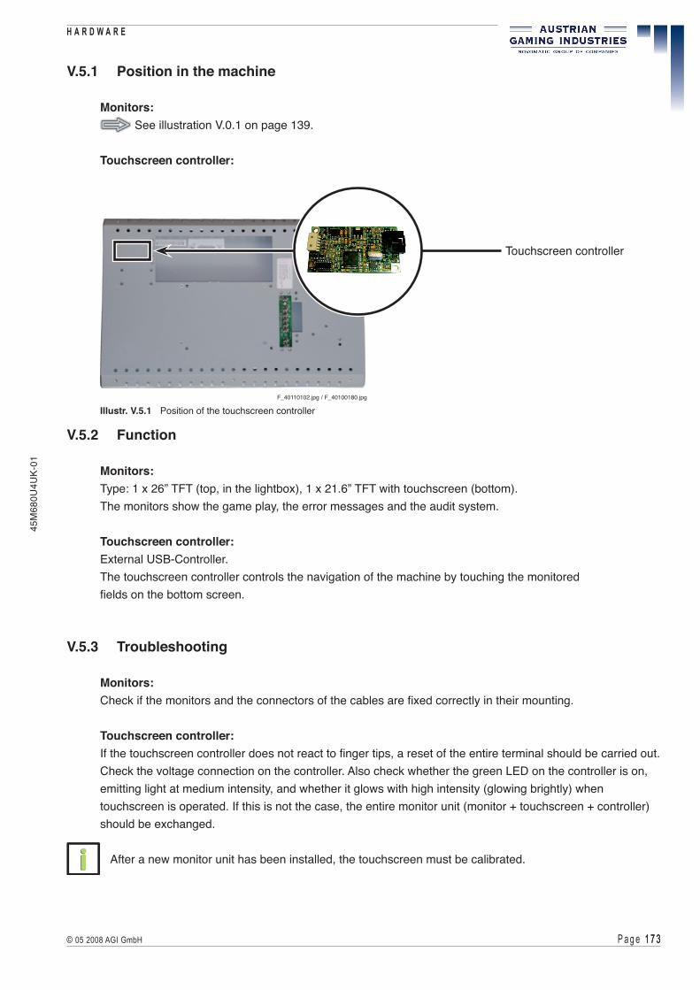
P a g e 1 � 3 1 � 3© 05 2008 AGI GmbH
H A R D W A R E45
M68
0U4U
K-01
V.5.1 Position in the machine
Monitors: See illustration V.0.1 on page 139.
Touchscreen controller:
Illustr. V.5.1 Position of the touchscreen controller
V.5.2 Function
Monitors:Type: 1 x 26” TFT (top, in the lightbox), 1 x 21.6” TFT with touchscreen (bottom). The monitors show the game play, the error messages and the audit system.
Touchscreen controller:External USB-Controller.The touchscreen controller controls the navigation of the machine by touching the monitored fields on the bottom screen.
V.5.3 Troubleshooting
Monitors:Check if the monitors and the connectors of the cables are fixed correctly in their mounting.
Touchscreen controller:If the touchscreen controller does not react to finger tips, a reset of the entire terminal should be carried out.Check the voltage connection on the controller. Also check whether the green LED on the controller is on, emitting light at medium intensity, and whether it glows with high intensity (glowing brightly) when touchscreen is operated. If this is not the case, the entire monitor unit (monitor + touchscreen + controller) should be exchanged.
After a new monitor unit has been installed, the touchscreen must be calibrated.
F_40110102.jpg / F_40100180.jpg
Touchscreen controller

P a g e 1 � 4 1 � 4 © 05 2008 AGI GmbH
H A R D W A R E
45M
680U
4UK-
01
V.5.4 Exchange of the monitors
If any defects cannot be repaired, the defective monitor has to be exchanged.
V.5.4.1 Exchange of the 21.6” TFT monitor
Illustr. V.5.2 Dismounting of the lower monitor
Dismounting instructions for the lower monitor
1) Open the Top Large Door and disconnect the machine from the mains. 2) Lift the monitor unit and turn it forward (see illustr. V.5.2). 3) Disconnect all plug and cable connectors of the monitor which has to be exchanged.
Do not touch circuit board! High voltage!
4) Grab the monitor with both hands and take it out of its retainer. 5) Exchange the defective monitor. 6) Assemble in reverse order.
F_PositionMonitor21.6.jpg F_TauschMonitor21.6.jpg

P a g e 1 � 5 1 � 5© 05 2008 AGI GmbH
H A R D W A R E45
M68
0U4U
K-01
V.5.4.2 Exchange of the 26” TFT monitor
Dismounting instructions for the upper monitor
1) Open the Top Large Door and disconnect the machine from the mains. 2) Press the securing lever downward and the locking lever sidewards. 3) Close the Top Large Door. 4) Remove the lightbox frame. 5) Open the monitor retainer by hoisting the frame on the right side and turn the frame
with the monitor unit to the left. 6) Disconnect the plug and cable connectors of the monitor.
Do not touch the circuit board! High voltage!
7) Grab the monitor unit with both hands and take it out of its retainer. 8) Release the four fixing screws (two on the left and two on the right) and take out the monitor of
its retainer. 9) Exchange the defective monitor. 10) Assemble in reverse order.
F_PositionMonitor26.jpg
F_TauschMonitor26.jpg
Illustr. V.5.4 Dismounting of the upper monitor
Illustr. V.5.3 Position of the upper monitor

P a g e 1 � 6 1 � 6 © 05 2008 AGI GmbH
H A R D W A R E
45M
680U
4UK-
01
Dismounting instructions for the touchscreen controller
1) Open the Top Large Door and disconnect the machine from the mains. 2) Dismount the lower monitor including the touchscreen controller
( see part V.5.4 - Exchange of the monitors). 3) release both fixing screws, disconnect the plug connection and remove the touchscreen controller
from the monitor unit. 4) Exchange the touchscreen controller. 5) Assemble in reverse order.
After a new monitor unit, a touchscreen or a touchscreen controller have been installed, the touchscreen must be calibrated.
V.5.6 Adjustment of the screen
At the rear side of the monitor, a print is attached for the adjustment of the brightness, contrast and geometry of the picture. The monitors can be adjusted via the buttons on the rear side of the respective monitor.
V.5.5 Exchange of the touchscreen controller
If any defects cannot be repaired, the defective touchscreen controller has to be exchanged.
F_40110102.jpg / F_40100180.jpg
Illustr. V.5.5 Exchange of the touchscreen controller
Touchscreen controller

P a g e 1 � � 1 � �© 05 2008 AGI GmbH
H A R D W A R E45
M68
0U4U
K-01
V.6 COOLFIRE II Motherboard
V.6.1 Position in the machine
V.6.2 Function
V.6.3 Connectors and components
V.6.4 Troubleshooting
V.6.5 Exchange of the main electronic unit COOLFIRE II
V.6.6 Exchange of the components

P a g e 1 � 8 1 � 8 © 05 2008 AGI GmbH
H A R D W A R E
45M
680U
4UK-
01
There are static-sensitive parts inside the machine which could be damaged by electricdischarge. Ground yourself by touching a ground strap inside the machine to neutralizeelectric charges before changing or maintaining inner parts.
Ground straps inside the machine are marked with yellow stickers as shown beside.
!

P a g e 1 � 9 1 � 9© 05 2008 AGI GmbH
H A R D W A R E45
M68
0U4U
K-01
V.6.1 Position in the machine
See illustration V.0.1 on page 139.
V.6.2 Function
Game control and drive of the components. The main electronics of the machine consists of the COOLFIRE II motherboard and several components. The security switch lock is located on the front side of the main electronic unit COOLFIRE II, between the the two grips, and is responsible for the storing of the accounting data. It is strictly prohibited to use a bridge connector for this switch (this might result in data loss!).
ATTENTIONWhen pushing in the main electronic unit COOLFIRE II make sure that the connectors lock in correctlyto the COOLFIRE II backplane.
!
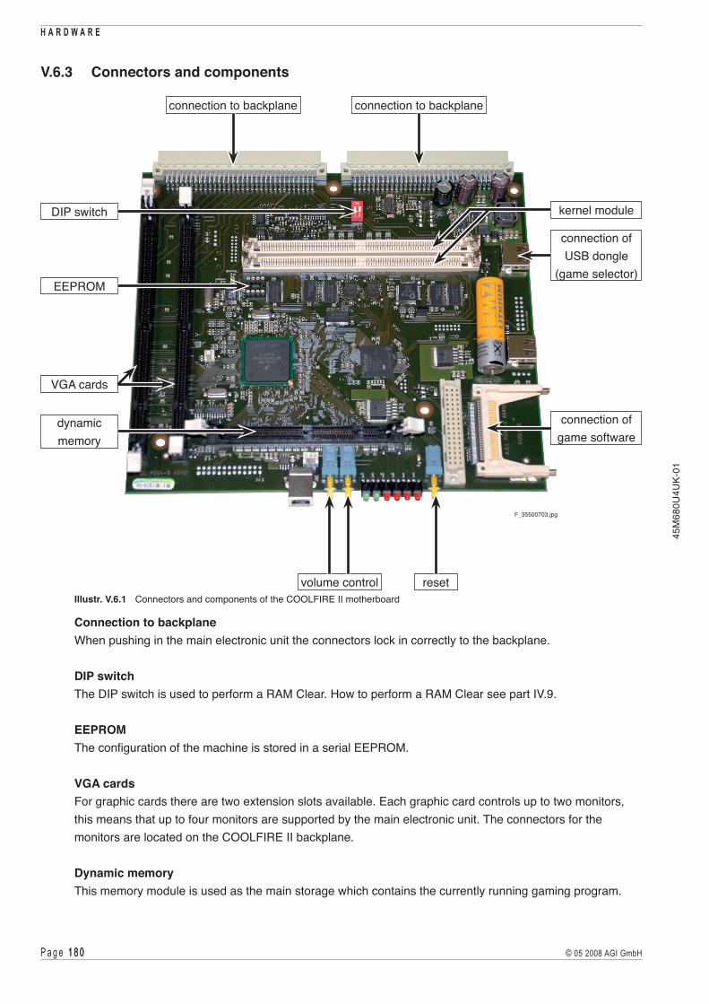
P a g e 1 8 0 1 8 0 © 05 2008 AGI GmbH
H A R D W A R E
45M
680U
4UK-
01
V.6.3 Connectors and components
Illustr. V.6.1 Connectors and components of the COOLFIRE II motherboard
Connection to backplane When pushing in the main electronic unit the connectors lock in correctly to the backplane.
DIP switch The DIP switch is used to perform a RAM Clear. How to perform a RAM Clear see part IV.9.
EEPROM The configuration of the machine is stored in a serial EEPROM.
VGA cards For graphic cards there are two extension slots available. Each graphic card controls up to two monitors, this means that up to four monitors are supported by the main electronic unit. The connectors for the monitors are located on the COOLFIRE II backplane.
Dynamic memory This memory module is used as the main storage which contains the currently running gaming program.
F_35500703.jpg
DIP switch
reset
connection to backplane connection to backplane
volume control
connection of game software
EEPROM
dynamic memory
connection of USB dongle
(game selector)
kernel module
VGA cards

P a g e 1 8 1 1 8 1© 05 2008 AGI GmbH
H A R D W A R E45
M68
0U4U
K-01
Kernel modules Both 80 pins SIMM sockets are provided for the flash memory SIMM modules to be plugged in. One of these sockets is used for the system software, the second socket is reserved for future extensions.
Connection of the USB dongle (Game Selector) The USB dongle provides for the game security and the time limitation. The dongle activates only certain, licensed games in the machine for a limited time period. The DIP switch on the dongle is used to select the module address in case of using further dongles.
F_CF2_USB_Dongle.eps
Illustr. V.6.2 USB dongle (game selector)
Connection of the game software A special compact flash card is used to store the gaming program. These compact flash cards include an implemented protection to avoid alterations of the content.
Volume control Use these buttons to adjust the volume of the acoustic signals of the machine.
Reset The reset function resets the COOLFIRE II motherboard to its initial state and restarts the gaming program.
V.6.4 Troubleshooting
If the displayed error messages of the COOLFIRE II motherboard (main electronic unit) cannot be cleared, the main electronic unit COOLFIRE II has to be exchanged.
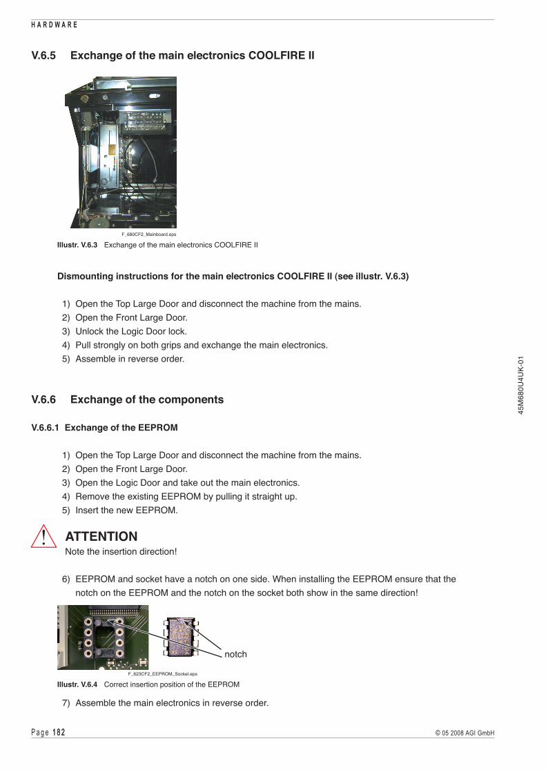
P a g e 1 8 2 1 8 2 © 05 2008 AGI GmbH
H A R D W A R E
45M
680U
4UK-
01
V.6.5 Exchange of the main electronics COOLFIRE II
Dismounting instructions for the main electronics COOLFIRE II (see illustr. V.6.3)
1) Open the Top Large Door and disconnect the machine from the mains. 2) Open the Front Large Door. 3) Unlock the Logic Door lock. 4) Pull strongly on both grips and exchange the main electronics. 5) Assemble in reverse order.
V.6.6 Exchange of the components
V.6.6.1 Exchange of the EEPROM
1) Open the Top Large Door and disconnect the machine from the mains. 2) Open the Front Large Door. 3) Open the Logic Door and take out the main electronics. 4) Remove the existing EEPROM by pulling it straight up. 5) Insert the new EEPROM.
ATTENTIONNote the insertion direction!
6) EEPROM and socket have a notch on one side. When installing the EEPROM ensure that the notch on the EEPROM and the notch on the socket both show in the same direction!
7) Assemble the main electronics in reverse order.
!
F_680CF2_Mainboard.eps
Illustr. V.6.3 Exchange of the main electronics COOLFIRE II
F_623CF2_EEPROM_Sockel.eps
notch
Illustr. V.6.4 Correct insertion position of the EEPROM

P a g e 1 8 3 1 8 3© 05 2008 AGI GmbH
H A R D W A R E45
M68
0U4U
K-01
V.6.6.2 Exchange of the VGA cards
1) Open the Top Large Door and disconnect the machine from the mains. 2) Open the Front Large Door. 3) Open the Logic Door and take out the main electronics. 4) Press both holding clips of the graphic card on the left and the right sideways. 5) Remove the graphic card from its socket by pulling it upwards. 6) Insert the new graphic card in upright position into its plug-in socket until both holding clips engage. 7) Assemble the main electronics in reverse order.
V.6.6.3 Exchange of the kernel modules
1) Open the Top Large Door and disconnect the machine from the mains. 2) Open the Front Large Door. 3) Open the Logic Door and take out the main electronics. 4) Press both holding clips of the kernel module sideways. 5) Remove the kernel module by pulling it upwards in tilted position. 6) Insert the new kernel module in tilted position into the plug-in socket and tilt the module backwards
until both holding clips engage. 7) Assemble the main electronics in reverse order.
V.6.6.4 Exchange of the USB dongle (Game Selector)
1) Open the Top Large Door and disconnect the machine from the mains. 2) Open the Front Large Door. 3) Open the Logic Door and take out the main electronics. 4) Remove the existing dongle by pulling it up rightwards. 5) Plug in the new dongle. 6) Assemble the main electronics in reverse order.
V.6.6.5 Exchange of the game software
1) Open the Top Large Door and disconnect the machine from the mains. 2) Open the Front Large Door. 3) Open the Logic Door and take out the main electronics. 4) Pull the existing compact flash card out of its plug-in socket sideways. 5) Insert the new compact flash card into its plug-in socket. 6) Assemble the main electronics in reverse order.
ATTENTIONAfter the components have been exchanged, a RAM Clear may be required!( see part IV.9 - RAM Clear).
!

P a g e 1 8 4 1 8 4 © 05 2008 AGI GmbH
H A R D W A R E
45M
680U
4UK-
01

P a g e 1 8 5 1 8 5© 05 2008 AGI GmbH
H A R D W A R E45
M68
0U4U
K-01
V.7 COOLFIRE II Backplane
V.7.1 Position in the machine
V.7.2 Function
V.7.3 Position of the components
V.7.4 Fuses and LEDs
V.7.5 Pin assignment
V.7.6 Troubleshooting
V.7.7 Exchange of the COOLFIRE II backplane

P a g e 1 8 6 1 8 6 © 05 2008 AGI GmbH
H A R D W A R E
45M
680U
4UK-
01
There are static-sensitive parts inside the machine which could be damaged by electricdischarge. Ground yourself by touching a ground strap inside the machine to neutralizeelectric charges before changing or maintaining inner parts.
Ground straps inside the machine are marked with yellow stickers as shown beside.
!

P a g e 1 8 � 1 8 �© 05 2008 AGI GmbH
H A R D W A R E45
M68
0U4U
K-01
V.7.1 Position in the machine
See illustration V.0.1 on page 139.
V.7.2 Function
The COOLFIRE II backplane achieves the following functions:
1) Voltage supply for the COOLFIRE II motherboard and the peripheral equipment. 2) Transmission of the complete communication between the COOLFIRE II master processor and all
peripheral devices inside the machine.
The communication between the peripheral equipment and the USB interface may be realised with an independent USB device for each peripheral unit.
V.7.3 Position of the components
Illustr. V.7.1 COOLFIRE II backplane connections
J29 J37J8J3J9J33J10J30J11J35
J16
J14
J31 J32 J17 J183J36 J13
J7 J38
J172
J1 J23
J41 J43 J26J40J22 J15 J19
J27
J25
J12
J5
J42
J34
J6 J20
J2J4
F_35500685.jpg
J1, J13, J29, J30, J31, J32, J33, J34, J35, J36, J37, J38, J172 - USB Power supply connectorJ2, J7, J8, J9, J10 - female USBJ3 - COM 0J4 - Ext MB detectJ5 - VGL 1 (COOLFIRE II motherboard J1)J6 - VGL 2 (COOLFIRE II motherboard J2)J11 - EthernetJ12 - Door Logger 2J14 - Add network cardJ15 - DebugJ16 - COM 2
J17 - COM 3J19, J20 - LoudspeakerJ22 - VGA2-AJ23 - Power supply connectorJ25 - VGA1-AJ26 - PowerJ27 - Door Logger 1J40 - VGA1-BJ41 - VGA2-BJ42 - SubwooferJ43 - COM 1J183 - Temperature sensor

P a g e 1 8 8 1 8 8 © 05 2008 AGI GmbH
H A R D W A R E
45M
680U
4UK-
01
V.7.4 Fuses and LEDs
35500685_P643_1_Detail3.jpg
Illustr. V.7.2 COOLFIRE II backplane fuses
+24V DC input for +5V DC COOLFIRE II backplane & +24V DC COOLFIRE II motherboard
Fuse F1 blade fuse 3ALED D3 +24V DC LED green OK LED red not OKLED D25 +5V DC LED red OK LED off not OK
+24V DC input for +12V DC COOLFIRE II backplane
Fuse F2 blade fuse 5ALED D29 +12V DC LED green OK LED off not OK
+24V DC input for +24V DC USB
Fuse F3 blade fuse 10ALED D30 +24V DC LED green OK LED off not OK
+24V DC input for +12V DC USB
Fuse F4 blade fuse 10ALED D27 +12V DC LED yellow OK LED off not OK
LEDD25
LEDD3
F1 LEDD30
LEDD27
LEDD29
F4F3F2

P a g e 1 8 9 1 8 9© 05 2008 AGI GmbH
H A R D W A R E45
M68
0U4U
K-01
35500685_P643_1_Detail6.jpg
Illustr. V.7.3 COOLFIRE II backplane position of the LEDs
Status signal for HUB
LED D7 LED red HUB1 enabledLED D18 LED green HUB1 disabledLED D5 LED red HUB1 configuredLED D16 LED green HUB1 non configuredLED D10 LED red HUB2 enabledLED D21 LED green HUB2 disabledLED D8 LED red HUB2 configuredLED D20 LED green HUB2 non configured
LED D34 LED D28LED D24LED D26
LED D17
LED D36 LED D6
LED D7
LED D16 LED D5 LED D18
LED D10
LED D20 LED D8 LED D21

P a g e 1 9 0 1 9 0 © 05 2008 AGI GmbH
H A R D W A R E
45M
680U
4UK-
01
Status signal for Ethernet
LED D34 LED green link “on“ LED off no link
LED D26 LED yellow collision “on“ LED off no collision
LED D24 LED red 100BT LED off 10BT
LED D28 LED yellow full duplex LED off half duplex
Status signal for USB:
LED D36 LED green OK LED blinking error
LED D6 LED red power LED off (40msec) communication
LED D17 LED yellow programming LED off OK

P a g e 1 9 1 1 9 1© 05 2008 AGI GmbH
H A R D W A R E45
M68
0U4U
K-01
V.7.5 Pin assignment
Connector J1, J13, J29, J30, J31, J32, J33, J34, J35, J36, J37, J38, J172USB Power supply connector (4 pin Mini Fit Jr. header)
PIN FUNCTION 01 +24V_USB 02 +12V_EX1 03 GND 04 GND
Connector J2, J7, J8, J9, J10Dual USB port
PIN FUNCTION A1 +5V_Dx_Dy A2 BP_D-x A3 BP_D+y A4 GND_Dx_Dy B1 +5V_Dx_Dy B2 BP_D-y B3 BP_D+y B4 GND_Dx_Dy
Connector J3COM 0 (8 pin Mini Fit header)
PIN FUNCTION 01 +5V_EX2 02 GND 03 +12V_EX1 04 GND 05 TXD1 06 nRTS1 07 RXD1 08 nCTS1
Connector J4Ext MB detect (2 pin lock header)
PIN FUNCTION 01 CF_LOCK2 02 CF_LOCK1
B1 B4B4
A1 A4
USB_dual.eps

P a g e 1 9 2 1 9 2 © 05 2008 AGI GmbH
H A R D W A R E
45M
680U
4UK-
01
Connector J5VGL 1 (96 pin DIN 41612 female connector)
PIN FUNCTIONA01 GNDA02 GNDA03 GNDA04 GNDA05 GNDA06 GNDA07 +5V_NGCA08 GNDA09 +5V_NGCA10 GNDA11 VGA1_DDC_DATAA12 VGA1_DDC_CLKA13 VGA1_HPDA14 +5V_NGCA15 GNDA16 +5V_NGCA17 GNDA18 VGA2_DDC_DATAA19 VGA2_DDC_CLKA20 VGA2_HPDA21 +5V_NGCA22 CF_LOCK1A23 CF_LOCK2A24 +3.3V DCA25 GNDA26 +3.3V DCA27 GNDA28 +3.3V DCA29 GNDA30 +3.3V DCA31 GNDA32 +3.3V DC
PIN FUNCTIONB01 GNDB02 VSYNC_OUT1B03 G_OUT1B04 R_OUT2B05 B_OUT2B06 HSYNC_OUT2B07 VGA1_TMDS-CLKB08 VGA1_TMDS+CLKB09 VGA1_TMDS-D1B10 VGA1_TMDS+D1B11 VGA1_TMDS-D3B12 VGA1_TMDS+D3B13 VGA1_TMDS-D5B14 VGA1_TMDS+D5B15 VGA2_TMDS-D0B16 VGA2_TMDS+D0B17 VGA2_TMDS-D2B18 VGA2_TMDS+D2B19 VGA2_TMDS-D4B20 VGA2_TMDS+D4B21 +2.5V DCB22 TX-B23 TX+B24 NW_TXDB25 ETXD2B26 NW_RXDB27 ERXD2B28 HUB_6MHZB29 nERTS1B30 ERXD1B31 EXT_D-2B32 EXT_D-1
PIN FUNCTIONC01 GNDC02 HSYNC_OUT1C03 B_OUT1C04 R_OUT1C05 G_OUT2C06 VSYNC_OUT2C07 VGA1_TMDS-D0C08 VGA1_TMDS+D0C09 VGA1_TMDS-D2C10 VGA1_TMDS+D2C11 VGA1_TMDS-D4C12 VGA1_TMDS+D4C13 VGA2_TMDS-CLKC14 VGA2_TMDS+CLKC15 VGA2_TMDS-D1C16 VGA2_TMDS+D1C17 VGA2_TMDS-D3C18 VGA2_TMDS+D3C19 VGA2_TMDS-D5C20 VGA2_TMDS+D5C21 GNDC22 RX-C23 RX+C24 nNW_RTSC25 nERTS2C26 nNW_CTSC27 nECTS2C28 nHUB_I/O_RESETC29 nECTS1C30 ETXD1C31 EXT_D+2C32 EXT_D+1

P a g e 1 9 3 1 9 3© 05 2008 AGI GmbH
H A R D W A R E45
M68
0U4U
K-01
PIN FUNCTIONA01 ETXD3A02 nERTS3A03 ERXD3A04 nECTS3A05 GNDA06 +5V_NGCA07 GNDA08 GNDA09 GNDA10 GNDA11 CHA_LOUTA12 CHB_LOUTA13 GNDA14 GNDA15 +5V_NGCA16 +5V_NGCA17 GNDA18 GNDA19 GNDA20 ETXD4A21 +12V DCA22 GNDA23 GNDA24 GNDA25 +24V DCA26 +24V DCA27 +24V DCA28 GNDA29 GNDA30 GNDA31 nPFIA32 GND
PIN FUNCTIONB01 GNDB02 GNDB03 CRT1_DDC_DATAB04 CRT1_DDC_CLKB05 CRT2_DDC_DATAB06 CRT2_DDC_CLKB07 GNDB08 GNDB09 CRT3_DDC_DATAB10 CRT3_DDC_CLKB11 CRT4_DDC_DATAB12 CRT4_DDC_CLKB13 E_100MB-B14 E-FDUPLEX+B15 +5V_NGCB16 +5V_NGCB17 GNDB18 GNDB19 GNDB20 nERTS4B21 +12V DCB22 GNDB23 GNDB24 GNDB25 +24V DCB26 +24V DCB27 +24V DCB28 GNDB29 GNDB30 GNDB31 MU/SB_LB32 N.C.
PIN FUNCTIONC01 B_OUT3C02 G_OUT3C03 R_OUT3C04 HSYNC_OUT3C05 VSYNC_OUT3C06 GNDC07 B_OUT4C08 G_OUT4C09 R_OUT4C10 HSYNC_OUT4C11 VSYNC_OUT4C12 VOUT_EX_SENC13 E_YL-C14 E_GR-C15 +5V_NGCC16 +5V_NGCC17 GNDC18 GNDC19 nECTS4C20 ERXD4C21 +12V DCC22 GNDC23 LOGIC_DOOR_DETECTC24 GNDC25 +24V DCC26 +24V DCC27 +24V DCC28 GNDC29 GNDC30 GNDC31 SV_LOUTC32 SV_ROUT
Connector J6VGL 2 (96 pin DIN 41612 female connector)

P a g e 1 9 4 1 9 4 © 05 2008 AGI GmbH
H A R D W A R E
45M
680U
4UK-
01
Connector J11Ethernet (RJ45) / dual USB combo
RJ45 PIN FUNCTION 1 TX+ 2 TX- 3 RX+ 4 N.C. 5 N.C. 6 RX- 7 N.C. 8 N.C.
USB PIN FUNCTION A1 +5V_D3_D4 A2 BP_D-3 A3 BP_D+3 A4 GND_D3_D4 B1 +5V_D3_D4 B2 BP_D-4 B3 BP_D+4 B4 GND_D3_D4
Connector J12Door Logger 2 (16 pin male connector)
PIN FUNCTION 01 KEY_GND 02 KEY_GND 03 IN_11 04 IN_12 05 IN_13 06 IN_14 07 IN_15 08 OUT_2 09 OUT_3 10 OUT_4 11 OUT_5 12 OUT_6 13 OUT_7 14 OUT_8 15 +12V_L 16 +12V_L
Connector J14Add network card (10 pin Micro Fit header)
PIN FUNCTION 01 NW_TXD 02 nNW_RTS 03 GND 04 GND 05 +5V_EX2 06 NW_RXD 07 nNW_CTS 08 GND 09 +24V_MFT 10 +12V_MFT
Connector J15Debug (16 pin female connector)
PIN FUNCTION 01 IN_17 02 GND 03 IN_18 04 +3V3_8051 05 IN_19 06 KPR_TEST 07 IN_20 08 nTDO 09 IN_21 10 KPR_RST/NMI 11 IN_22 12 N.C. 13 IN_23 14 RX_KP 15 LOGIC_DOOR_DETECT 16 TXD_KP
B1 B4
A1 A4
18
RJ45.eps

P a g e 1 9 5 1 9 5© 05 2008 AGI GmbH
H A R D W A R E45
M68
0U4U
K-01
Connector J16COM 2 (10 pin male connector)
PIN FUNCTION 01 N.C. 02 N.C. 03 RXD3 04 nRTS3 05 TXD3 06 nCTS3 07 N.C. 08 +5V_EX3 09 GND 10 N.C.
Connector J17COM 3 (10 pin male connector)
PIN FUNCTION 01 N.C. 02 N.C. 03 RXD4 04 nRTS4 05 TXD4 06 nCTS4 07 N.C. 08 +5V_EX3 09 GND 10 N.C.
Connector J19, J20Loudspeaker (4 pin Micro Fit header)
PIN FUNCTION 01 SAOUT1+ 02 SAOUT1- 03 SAOUT2+ 04 SAOUT2-
Connector J22VGA2-A (15 pin D-Sub female connector)
PIN FUNCTION 01 R_OUT2 02 G_OUT2 03 B_OUT2 04 N.C. 05 GND 06 GND 07 GND 08 GND 09 +5V_V2 10 GND 11 N.C. 12 CRT2_DDC_DATA 13 HSYNC_OUT2 14 VSYNC_OUT2 15 CRT2_DDC_CLK
Connector J23Power supply connector (6 pin Mini Fit Jr. header)
PIN FUNCTION 01 +24V_USB 02 +12V_EX1 03 +5V_EX4 04 GND 05 GND 06 nPFI

P a g e 1 9 6 1 9 6 © 05 2008 AGI GmbH
H A R D W A R E
45M
680U
4UK-
01
Connector J25VGA1-A (15 pin D-Sub female connector)
PIN FUNCTION 01 R_OUT1 02 G_OUT1 03 B_OUT1 04 N.C. 05 GND 06 GND 07 GND 08 GND 09 +5V_V1 10 GND 11 N.C. 12 CRT1_DDC_DATA 13 HSYNC_OUT1 14 VSYNC_OUT1 15 CRT1_DDC_CLK
Connector J26Power (10 pin Mini Fit header)
PIN FUNCTION 01 +24V_CF 02 +24V_CF 03 +24V_CF 04 +24V_CF 05 PFI_N 06 GND 07 GND 08 GND 09 PGND 10 PGND
Connector J27Door Logger 1 (34 pin male connector)
PIN FUNCTION 01 IN_1_MAIN_DOOR_RX 02 +3.3V_DP 03 OUT_1_MAIN_DOOR_TR 04 +3.3V_DP 05 DOOR_GND 06 IN_22 07 IN_23 08 IN_20 09 IN_21 10 IN_18 11 IN_19 12 IN_16 13 IN_17 14 DOOR_GND 15 DOOR_GND 16 DOOR_GND 17 IN_2 18 DOOR_GND 19 IN_3 20 DOOR_GND 21 IN_4 22 DOOR_GND 23 IN_5 24 DOOR_GND 25 IN_6 26 DOOR_GND 27 IN_7 28 DOOR_GND 29 IN_8 30 DOOR_GND 31 IN_9 32 DOOR_GND 33 IN_10 34 DOOR_GND

P a g e 1 9 � 1 9 �© 05 2008 AGI GmbH
H A R D W A R E45
M68
0U4U
K-01
Connector J40VGA1-B (15 pin D-Sub female connector)
PIN FUNCTION 01 R_OUT3 02 G_OUT3 03 B_OUT3 04 N.C. 05 GND 06 GND 07 GND 08 GND 09 +5V_V3 10 GND 11 N.C. 12 CRT3_DDC_DATA 13 HSYNC_OUT3 14 VSYNC_OUT3 15 CRT3_DDC_CLK
Connector J41VGA2-B (15 pin D-Sub female connector)
PIN FUNCTION 01 R_OUT4 02 G_OUT4 03 B_OUT4 04 N.C. 05 GND 06 GND 07 GND 08 GND 09 +5V_V4 10 GND 11 N.C. 12 CRT4_DDC_DATA 13 HSYNC_OUT4 14 VSYNC_OUT4 15 CRT4_DDC_CLK
Connector J42Subwoofer (2 pin Mini Fit header)
PIN FUNCTION 01 OUT_N- 02 OUT_P+
Connector J43COM 1 (9 pin D-Sub male connector)
PIN FUNCTION 01 +12V_EX1 02 RXD2 03 TXD2 04 N.C. 05 GND 06 N.C. 07 nRTS2 08 nCTS2 09 +5V_EX3
Connector J183Temperature sensor (3 pin Lock header)
PIN FUNCTION 01 GND 02 VOUT_EX_SEN 03 N.C.

P a g e 1 9 8 1 9 8 © 05 2008 AGI GmbH
H A R D W A R E
45M
680U
4UK-
01
V.7.6 Troubleshooting
If any defects occur, check whether all connectors are fixed correctly on the COOLFIRE II backplane.
V.7.7 Exchange of the COOLFIRE II backplane
If any defects of the COOLFIRE II backplane cannot be repaired, the defective part has to be exchanged. If any defects occur afterwards, the complete backplane has to be exchanged.
F_680CF2_Backplane.eps
Illustr. V.7.4 Exchange of the backplane
Dismounting instructions for the COOLFIRE II backplane (see illustr. V.7.4)
1) Open the Top Large Door and disconnect the machine from the mains. 2) Open the Front Large Door. 3) Dismount the COOLFIRE II motherboard ( see part V.6.5). 4) Remove the hopper cover and take out the hopper in forward direction. 5) Unplug all connectors of the COOLFIRE II backplane and release the fixing screws. 6) Unscrew the COOLFIRE II backplane and exchange it. 7) Assemble in reverse order.

P a g e 1 9 9 1 9 9© 05 2008 AGI GmbH
H A R D W A R E45
M68
0U4U
K-01
V.8 Key Panel Module
V.8.1 Position in the machine
V.8.2 Function
V.8.3 Pin assignment
V.8.4 Troubleshooting
V.8.5 Exchange of the key panel module

P a g e 2 0 0 2 0 0 © 05 2008 AGI GmbH
H A R D W A R E
45M
680U
4UK-
01
There are static-sensitive parts inside the machine which could be damaged by electricdischarge. Ground yourself by touching a ground strap inside the machine to neutralizeelectric charges before changing or maintaining inner parts.
Ground straps inside the machine are marked with yellow stickers as shown beside.
!

P a g e 2 0 1 2 0 1© 05 2008 AGI GmbH
H A R D W A R E45
M68
0U4U
K-01
V.8.1 Position in the machine
F_680CF2_KeyPanel.eps
key panel module
Illustr. V.8.1 Position of the key panel module
Lamps, buttons,door switches andkey switches
Power supplyUSB connection to the backplane
DIP switch
F_CF2_KeyPanelModul_P562.eps
Illustr. V.8.2 Connections of the key panel module
V.8.2 Function
The key panel module consists of a micro processor, which reads-in the status of all buttons and switches of the machine and illuminates the corresponding lamps.
V.8.3 Pin assignment
The connection between COOLFIRE II backplane and key panel module is realised by an USB interface. The key panel module and the lamps are supplied with power by the plug Power Supply. The DIP switch is used to select the module address in case of using further modules.

P a g e 2 0 2 2 0 2 © 05 2008 AGI GmbH
H A R D W A R E
45M
680U
4UK-
01
V.8.4 Troubleshooting
If any defects occur, check whether all connectors are fixed correctly to the key panel module. If the defect cannot be repaired, the key panel module has to be exchanged.
V.8.5 Exchange of the key panel module
F_680CF2_KeyPanel.eps
key panel module
Illustr. V.8.3 Exchange of the key panel module
Dismounting instructions for the key panel module (see illustr. V.8.3)
1) Open the Top Large Door and disconnect the machine from the mains. 2) Release all connectors of the key panel module. 3) Release the fixing screws and remove the key panel module. 4) Exchange the key panel module. 5) Assemble in reverse order.

P a g e 2 0 3 2 0 3© 05 2008 AGI GmbH
H A R D W A R E45
M68
0U4U
K-01
V.9 Top light
V.9.1 Position in the machine
V.9.2 Function
V.9.3 Exchange of the top light
V.9.4 Exchange of the top light illumination

P a g e 2 0 4 2 0 4 © 05 2008 AGI GmbH
H A R D W A R E
45M
680U
4UK-
01
There are static-sensitive parts inside the machine which could be damaged by electricdischarge. Ground yourself by touching a ground strap inside the machine to neutralizeelectric charges before changing or maintaining inner parts.
Ground straps inside the machine are marked with yellow stickers as shown beside.
!

P a g e 2 0 5 2 0 5© 05 2008 AGI GmbH
H A R D W A R E45
M68
0U4U
K-01
Illustr. V.9.2 Fixing screws of the top light in the lightboxF_680CF2_LKRE27_TauschLichtturmDetail.jpg
V.9.1 Position in the machine
See illustration V.0.1 on page 139.
V.9.2 Function
The top light indicates the different status of operation (jackpot, error, service, etc.). ( see part IV.7 - Top light).
V.9.3 Exchange of the top light
Dismounting instructions for the top light
1) Open the Top Large Door and disconnect the machine from the mains. 2) Press the securing lever downward and push the locking lever sidewards. 3) Close the Top Large Door. 4) Remove the lightbox frame. 5) Release the fixing screws and the connectors of the top light and exchange it (see illustr. V.9.2). 6) Assemble in reverse order.
F_680CF2_LKRE27_TauschLichtturm.jpg
Illustr. V.9.1 Dismounting of the upper monitor

P a g e 2 0 6 2 0 6 © 05 2008 AGI GmbH
H A R D W A R E
45M
680U
4UK-
01
V.9.4 Exchange of the top light illumination
Dismounting instructions for the top light illumination
1) Open the Top Large Door and disconnect the machine from the mains. 2) Release the cap nut of the upper cover of the top light and remove the covers (see illustr. V.9.3). 3) Remove the defective lamp by pulling it out of its socket and remove it. 4) Assemble in reverse order .
F_CS_LT_Teile.eps
Illustr. V.9.3 Components of the top light

P a g e 2 0 � 2 0 �© 05 2008 AGI GmbH
H A R D W A R E45
M68
0U4U
K-01
V.10 Illumination
V.10.1 Bill acceptor illumination
V.10.2 Key illumination

P a g e 2 0 8 2 0 8 © 05 2008 AGI GmbH
H A R D W A R E
45M
680U
4UK-
01
There are static-sensitive parts inside the machine which could be damaged by electricdischarge. Ground yourself by touching a ground strap inside the machine to neutralizeelectric charges before changing or maintaining inner parts.
Ground straps inside the machine are marked with yellow stickers as shown beside.
!

P a g e 2 0 9 2 0 9© 05 2008 AGI GmbH
H A R D W A R E45
M68
0U4U
K-01
V.10.1 Bill acceptor illumination
V.10.1.1 Position in the machine
F_680CF2_Epic950.eps
bill acceptor illumination
Illustr. V.10.1 Bill acceptor illumination
F_680CF2_BNP_Bel.eps
lamp on the illumination print
Illustr. V.10.2 Exchange of the bill acceptor illumination
V.10.1.2 Function
Green or blue illumination: bill acceptor is ready Red illumination: bill acceptor is out of order
V.10.1.3 Exchange of the bill acceptor illumination
1) Open the Top Large Door and disconnect the machine from the mains. 2) Turn the defective lamp 90° and take it out of the illumination print (see illustr. V.10.2). 3) Exchange the defective lamp. 4) Assemble in reverse order.
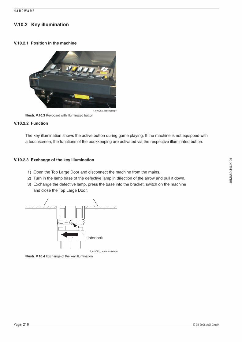
P a g e 2 1 0 2 1 0 © 05 2008 AGI GmbH
H A R D W A R E
45M
680U
4UK-
01
V.10.2 Key illumination
V.10.2.1 Position in the machine
interlock
F_623CF2_Lampensockel.eps
Illustr. V.10.4 Exchange of the key illumination
F_680CF2_TastenBel.eps
Illustr. V.10.3 Keyboard with illuminated button
V.10.2.2 Function
The key illumination shows the active button during game playing. If the machine is not equipped with a touchscreen, the functions of the bookkeeping are activated via the respective illuminated button.
V.10.2.3 Exchange of the key illumination
1) Open the Top Large Door and disconnect the machine from the mains. 2) Turn in the lamp base of the defective lamp in direction of the arrow and pull it down. 3) Exchange the defective lamp, press the base into the bracket, switch on the machine
and close the Top Large Door.

P a g e 2 11 2 11© 05 2008 AGI GmbH
H A R D W A R E45
M68
0U4U
K-01
V.11 Mechanical meters
V.11.1 Position in the machine
V.11.2 Function
V.11.3 Troubleshooting
V.11.4 Exchange of the mechanical meters

P a g e 2 1 2 2 1 2 © 05 2008 AGI GmbH
H A R D W A R E
45M
680U
4UK-
01
There are static-sensitive parts inside the machine which could be damaged by electricdischarge. Ground yourself by touching a ground strap inside the machine to neutralizeelectric charges before changing or maintaining inner parts.
Ground straps inside the machine are marked with yellow stickers as shown beside.
!

P a g e 2 1 3 2 1 3© 05 2008 AGI GmbH
H A R D W A R E45
M68
0U4U
K-01
V.11.1 Position in the machine
See illustration V.0.1 on page 139.
V.11.2 Function
These mechanical meters represent the respective values of the machine accounting.Because of the variety of country-specific configurations the following illustration shows the “Novomatic Standard” as an example.
Example: Novomatic Standard
BET WIN REMOTE HANDPAY
BILLS DROP GAMES TOKENZ_Zählwerke.eps
BET Total value of all bets in credits. WIN Total value of all wins in credits. REMOTE Total value of all credits added via the remote function. HANDPAY Total value of all credits paid out via handpay. BILLS Total value of all bills inserted in credits. DROP Total value of all coins diverted to the cashbox in credits. GAMES Total value of all games played. TOKEN Total value of all tokens accepted

P a g e 2 1 4 2 1 4 © 05 2008 AGI GmbH
H A R D W A R E
45M
680U
4UK-
01
V.11.3 Troubleshooting
Check the connectors of the meter unit. If an error message is triggered by a malfunction or non-activation of individual meters the device must be removed from operation and the meters circuit board must be exchanged.
V.11.4 Exchange of the meters
If any defects cannot be repaired, the defective meters have to be exchanged.
fixing screws
F_680CF2_Zaehlw2.epsF_680CF2_Zaehlw1.eps
meters
Illustr. V.11.1 Position of the meters (front view) Illustr. V.11.2 Fixing screws of the meters
Dismounting instructions for the mechanical meters
1) Open the Top Large Door and disconnect the machine from the mains. 2) Open the Front Large Door. 3) Disconnect the plug connectors from the meters. 4) Release both fixing screws (see illustr. V.11.2) and take out the complete meter unit in
upward direction. 5) Release the screws of the meter cover and remove the cover. 6) Exchange the defective meters. 7) Assemble in reverse order.

P a g e 2 1 5 2 1 5© 05 2008 AGI GmbH
H A R D W A R E45
M68
0U4U
K-01
V.12 Door switches
V.12.1 Position in the machine
V.12.2 Function
V.12.3 Troubleshooting V.12.4 Exchange of the door switches

P a g e 2 1 6 2 1 6 © 05 2008 AGI GmbH
H A R D W A R E
45M
680U
4UK-
01
There are static-sensitive parts inside the machine which could be damaged by electricdischarge. Ground yourself by touching a ground strap inside the machine to neutralizeelectric charges before changing or maintaining inner parts.
Ground straps inside the machine are marked with yellow stickers as shown beside.
!

P a g e 2 1 � 2 1 �© 05 2008 AGI GmbH
H A R D W A R E45
M68
0U4U
K-01
V.12.1 Position in the machine
F_680CF2_KeyPanel.eps F_680CF2_Doorswitch2.eps
Door switches:Front Large DoorStacker Door
Illustr. V.12.1 Door switch Top Large Door
Illustr. V.12.3 Door switchF_Türschalter.eps
Illustr. V.12.2 Door switch Front Large Door and Stacker Door
V.12.2 Function
The door switches monitor the openings and closings of the Top Large Door, the Front Large Door and of the Stacker Door.
V.12.3 Troubleshooting
Check the connectors of the door switches for any damages.
V.12.4 Exchange of the door switches
If any defects cannot be repaired, the defective door switch has to be exchanged.
Dismounting instructions for the door switches
1) Open the Top Large Door and disconnect the machine from the mains. 2) If the door switch of the Front Large Door or of the Stacker Door has to be exchanged,
please open the respective door. 3) Release the plug connectors of the defective door switch. 4) Unscrew the fixing screws and remove the door switch. 5) Exchange the defective door switch. 6) Assemble in reverse order.

P a g e 2 1 8 2 1 8 © 05 2008 AGI GmbH
H A R D W A R E
45M
680U
4UK-
01

P a g e 2 1 9 2 1 9© 05 2008 AGI GmbH
H A R D W A R E45
M68
0U4U
K-01
V.13 Loudspeakers
V.13.1 Position in the machine
V.13.2 Function
V.13.3 Volume control
V.13.4 Troubleshooting
V.13.5 Exchange of the loudspeakers

P a g e 2 2 0 2 2 0 © 05 2008 AGI GmbH
H A R D W A R E
45M
680U
4UK-
01
There are static-sensitive parts inside the machine which could be damaged by electricdischarge. Ground yourself by touching a ground strap inside the machine to neutralizeelectric charges before changing or maintaining inner parts.
Ground straps inside the machine are marked with yellow stickers as shown beside.
!

P a g e 2 2 1 2 2 1© 05 2008 AGI GmbH
H A R D W A R E45
M68
0U4U
K-01
V.13.1 Position in the machine
See illustration V.0.1 on page 139.
V.13.2 Function
Type: 2 x full-range loudspeakers oval (8 Ohm, 3 W), in the lightbox 2 x HiFi high-end woofers 10 cm (4 Ohm, 30 W) in Front Large Door and Stacker Door
The loudspeakers are used for acoustic output of game sounds and also audio warnings in case of any errors.
V.13.3 Volume control
Use the buttons on the COOLFIRE II motherboard to adjust the volume.
buttons forvolume control
F_680CF2_Mainboard.eps
Illustr. V.13.1 Volume control
V.13.4 Troubleshooting
Check the connectors of the loudspeakers. If any defects cannot be repaired, exchange the defective part.

P a g e 2 2 2 2 2 2 © 05 2008 AGI GmbH
H A R D W A R E
45M
680U
4UK-
01
V.13.5 Exchange of the loudspeakers
If any defects cannot be repaired, the defective loudspeaker has to be exchanged.
V.13.5.1 Exchange of the loudspeakers in the lightbox
F_FV680CF2_entriegeln.jpg
Illustr. V.13.2 Securing and locking lever
Dismounting instructions for the loudspeakers in the lightbox
1) Open the Top Large Door and disconnect the machine from the mains. 2) Press the securing lever downward and push the locking lever sidewards. 3) Close the Top Large Door. 4) Remove the lightbox frame. 5) Release the fixing screws of the loudspeaker rail on the lightbox back wall. 6) Dismount carefully the loudspeaker rail. 7) Disconnect the plug and cable connections of the defective loudspeaker. 8) Release the four fixing screws of the loudspeaker and remove the loudspeaker. 9) Exchange the defective loudspeaker. 10) Assemble in reverse order.
F_FV680CF2_entfernen.jpg
Illustr. V.13.3 LightboxF_FV680CF2_Monitor_schwenken.jpg
F_FV680CF2_entfernen.jpg
Illustr. V.13.4 Exchange of the loudspeakers in the lightbox

P a g e 2 2 3 2 2 3© 05 2008 AGI GmbH
H A R D W A R E45
M68
0U4U
K-01
F_680CF2_LS_FLD.eps
Illustr. V.13.5 Loudspeakers in the Drop Door
Dismounting instructions for the loudspeaker in the Drop Door
1) Open the Top Large Door and disconnect the machine from the mains. 2) Open the Drop Door. 3) Disconnect the plug and cable connections of the defective loudspeaker. 4) Release the four fixing screws of the loudspeaker and remove the loudspeaker. 5) Exchange the defective loudspeaker. 6) Assemble in reverse order.
V.13.5.2 Exchange of the loudspeaker in the Drop Door

P a g e 2 2 4 2 2 4 © 05 2008 AGI GmbH
H A R D W A R E
45M
680U
4UK-
01

P a g e 2 2 5 2 2 5© 05 2008 AGI GmbH
H A R D W A R E45
M68
0U4U
K-01
V.14 Ticket printer
V.14.1 Position in the machine
V.14.2 Function
V.14.3 Troubleshooting
V.14.4 Exchange of the ticket printer
V.14.5 Removing loaded tickets
V.14.6 Loading tickets V.14.7 Status LED
V.14.8 Firmware Upgrade

P a g e 2 2 6 2 2 6 © 05 2008 AGI GmbH
H A R D W A R E
45M
680U
4UK-
01
There are static-sensitive parts inside the machine which could be damaged by electricdischarge. Ground yourself by touching a ground strap inside the machine to neutralizeelectric charges before changing or maintaining inner parts.
Ground straps inside the machine are marked with yellow stickers as shown beside.
!

P a g e 2 2 � 2 2 �© 05 2008 AGI GmbH
H A R D W A R E45
M68
0U4U
K-01
Test print: Switch to the AUDIT MENU item DIAGNOSTIC > PRINTER to print a test ticket.
ATTENTIONA test print without paper in the printer may damage the thermal print head!
If any defects cannot be repaired, the ticket printer has to be exchanged or may be disabled to continue the operation of the game without ticket printer. To do so disable the ticket printer in the AUDIT MENU item MACHINE SETUP > PRINTER SETUP. In further consequence, the defective ticket printer has to be exchanged.
V.14.1 Position in the machine
See illustration V.0.1 on page 139.
V.14.2 Function
Type: ITHACA EPIC 950, GEN2 Future Logic or compatible. The player can have remaining credits printed on a ticket by pressing the CASH button on the device. The ticket can be redeemed at the cash desk.
V.14.3 Troubleshooting
Check whether the ticket printer is fixed correctly in its mounting.
!
F_680CF2_Epic950_offen.epsF_680CF2_Epic950.eps
Printer Door
Illustr. V.14.1 Ticket printer in the bill acceptor hood Illustr. V.14.2 Printer Door, open

P a g e 2 2 8 2 2 8 © 05 2008 AGI GmbH
H A R D W A R E
45M
680U
4UK-
01
V.14.4 Exchange of the ticket printer
If any defects cannot be repaired, the ticket printer has to be exchanged.
!
F_680CF2_TP_Ausbau2.eps F_680CF2_TP_Ausbau3.epsF_680CF2_TP_Ausbau1.eps
locking lever (right)
Illustr. V.14.3 Unlocking of the ticket printer Illustr. V.14.4 Disassembly of the ticket printer
Dismounting instructions for the ticket printer
1) Open the Top Large Door and disconnect the machine from the mains. 2) Unlock the locking levers on the right and left side of the ticket printer retainer (see illustr. V.14.3). 3) Pull the ticket printer out of its retainer carefully (see illustr. V.14.4). 4) Release the four fixing screws of the bottom plate of the ticket printer and remove the bottom plate 5) Unplug the plug and cable connectors of the ticket printer. 6) Exchange the defective ticket printer. 7) Assemble in reverse order.
ATTENTIONToavoiddamagesofthemouthpiecebyinsertingtheticketprinterfirstinsertthemouthpieceintotheticket printer retainer carefully. After this, the complete printer unit can be inserted.

P a g e 2 2 9 2 2 9© 05 2008 AGI GmbH
H A R D W A R E45
M68
0U4U
K-01
V.14.5 Removing loaded tickets
The printer has to ways to remove unused tickets from the printer mechanism assembly:
1) The first way is to release the ticket cover by lifting and rotating backwards, this will relieve pressure to the plate and tickets can be removed. This also will allow an opening the provides space to clean the print head or to check the printer for jams.
2) The second way is to use the feed button, which will feed out tickets from within the printer mechanism assembly.
V.14.5.1 Ticket printer ITHACA EPIC 950
F_EPIC950_Tickets_entf.eps
ticket tray
FEED
READY
PAPER
OPEN
FAULT
feed buttonrelease lever
ticket cover
Illustr. V.14.5 Removing loaded tickets - ITHACA EPIC 950
Removing loaded tickets by opening the ticket cover
1) Open the Printer Door. 2) Lift and rotate the ticket cover backwards, towards the rear of the printer. 3) Remove all tickets from the ticket path and check for any debris. 4) Remove any remaining tickets from the ticket tray. 5) Rotate the ticket cover back into the latched (magnetic) position. 6) Proceed with ticket loading procedure ( see part. V.14.6).
Removing loaded tickets by using the feed button
1) Open the Printer Door. 2) Separate ticket currently loaded in the platen assembly from the ticket stack and remove any remaining
ticket stack. 3) Press the feed button to eject the ticket. 4) Proceed with ticket loading procedure ( see part. V.14.6).

P a g e 2 3 0 2 3 0 © 05 2008 AGI GmbH
H A R D W A R E
45M
680U
4UK-
01
V.14.5.2 Ticket printer GEN2 Future Logic
F_GEN2_offen.eps
F_GEN2_Abdeckung.eps
ticket cover
FEED
READY
PAPER
OPEN
FAULT
feed button
Illustr. V.14.6 Removing loaded tickets - GEN2 Future Logic
Removing loaded tickets by opening the ticket cover
1) Open the Printer Door. 2) Open the ticket cover by pressing the platen release lever. The spring-loaded cover opens,
exposing the ticket path. 3) Remove any remaining tickets. 4) Close the ticket cover. 5) Proceed with ticket loading procedure ( see part. V.14.6).
Removing loaded tickets by using the feed button
1) Open the Printer Door. 2) Separate the ticket currently loaded in the platen assembly from the ticket stack and remove any
remaining ticket stack. 3) Press the feed button to eject the ticket. 4) Proceed with ticket loading procedure ( see part. V.14.6).

P a g e 2 3 1 2 3 1© 05 2008 AGI GmbH
H A R D W A R E45
M68
0U4U
K-01
V.14.6 Loading tickets
V.14.6.1 Ticket printer ITHACA EPIC 950
When loading a new ticket stack, make sure that there is power to the printer. The printer’s ticket tray is integrated with a guide to direct the ticket into the printer mechanism.
F_Epic950_refill1.eps F_Epic950_refill2.eps
Illustr. V.14.7 Loading tickets - ITHACA EPIC 950
1) Open the Printer Door. 2) Remove any remaining tickets from the tray ( see part V.14.5). 3) Load tickets into the ticket tray. Make sure that the black label is facing you. 4) Insert the leading ticket into the printer mechanism assembly‘s insertion guide are. The ticket
should be fed about a 1/2 cm into the mechanism; at this time the printer automatically completes the feeding process.
5) Close the Printer Door.

P a g e 2 3 2 2 3 2 © 05 2008 AGI GmbH
H A R D W A R E
45M
680U
4UK-
01
V.14.6.2 Ticket printer GEN2 Future Logic
When loading a new ticket stack, make sure that there is power to the printer. The printer’s ticket tray is integrated with a guide to direct the ticket into the printer mechanism.
F_GEN2_Refill1.eps F_GEN2_Refill2.eps
Illustr. V.14.8 Loading tickets - GEN2 Future Logic
1) Open the Printer Door. 2) Remove any remaining tickets from the tray ( see part V.14.5). 3) Load tickets into the ticket tray. Make sure that the black label is facing you. 4) Insert the leading ticket into the printer mechanism assembly’s insertion guide area. The ticket should
be fed about 1/2 cm into the mechanism; at this time the printer automatically completes the feeding process.
5) Close the Printer Door.

P a g e 2 3 3 2 3 3© 05 2008 AGI GmbH
H A R D W A R E45
M68
0U4U
K-01
V.14.7 Status LED
The status LED report the status of the printer whenever power is present.
V.14.7.1 Ticket printer ITHACA EPIC 950
FEED
READY
PAPER
OPEN
FAULT
F_CS_EPIC950_frei.eps / Z_Epic950_Statusanzeige.eps
Illustr. V.14.9 Status LED ITHACA EPIC 950
CONDITIONLED
READY PAPER OPEN FAULTPrinter ready ON - - -Ticket cover open ON - ON -Chassis open ON - BLINK -Ticket out ON ON - -Ticket low ON BLINK - -Paper jam ON - - BLINK
Troubleshooting
ERROR ERROR DESCRIPTION TROUBLESHOOTINGTicket cover open The ticket cover is open. Close the ticket cover.Chassis open The chassis is open. Close the chassis.Ticket out Results when the printer does not
detect any paper present.Load a new ticket stack.
Ticket low Printer will run out of tickets soon. Load a new ticket stack soon.Paper jam Results when the printer detects an
error in the ticket path for presenting the ticket to the customer.
Open the ticket cover and inspect for a jammed ticket.

P a g e 2 3 4 2 3 4 © 05 2008 AGI GmbH
H A R D W A R E
45M
680U
4UK-
01
V.14.7.2 Ticket printer GEN2 Future Logic
F_GEN2_Gesamt_leer.eps / Z_GEN2_Statusanzeige.eps
FEED
READY
PAPER
OPEN
FAULT
Illustr. V.14.10 Status LED GEN2 Future Logic
CONDITIONLED
READY PAPER OPEN FAULTPrinter ready BLINK - - -Ticket out - ON - -Ticket cover open - - ON -Missing black label - ON - -Paper jam ON - - BLINK
Troubleshooting
ERROR ERROR DESCRIPTION TROUBLESHOOTINGTicket out Results when the printer does not
detect any paper present.Load a new ticket stack.
Ticket cover open The ticket cover is open. Close the ticket cover.Black label on tickets missing
Results if the inserted ticket type is the wrong kind of paper or if the paper was inserted in the wrong direction (so the black label is rotated 180°).
Insert the ticket stack in correct direction e.g. insert the correct kind of paper.
Paper jam Results when the printer detects an error in the ticket path for presenting the ticket to the customer.
Open the ticket cover and inspect for jammed tickets.

P a g e 2 3 5 2 3 5© 05 2008 AGI GmbH
H A R D W A R E45
M68
0U4U
K-01
V.14.8 Firmware Upgrade
Before performing a firmware upgrade please contact our Technical Support (phone +43 2252 606-285).
V.14.8.1 Ticket printer ITHACA EPIC 950
Occasionally the printer can require a firmware upgrade. For this purpose the printer feature a firmware download port (see illustr. V.14.11).
89
F_Epic950_Firmware1.eps
FEED
READY
PAPER
OPEN
FAULT
firmware and graphics download port
Z_Epic950_Statusanzeige.eps / F_Epic950_Firmware.eps
Illustr. V.14.11 Firmware Upgrade ITHACA EPIC 950
Upgrade procedure
1) Open the Top Large Door and disconnect the machine from the mains. 2) Disassemble the ticket printer ( see part V.14.4). 3) Connect the disassembled printer to the power supply of the machine. 4) For the upgrade procedure the printer needs tickets. If necessary, load a new ticket stack. 5) Connect the printer to the PC by using the download cable (download port, see illustr. V.14.11). 6) Open the ticket cover. 7) Apply power to the printer by switching on the machine, while holding the “FEED” button on the printer.
The “READY” LED will be blinking and the “FAULT” LED should be on solid. 8) Next run the firmware download program and select the proper communications port. 9) Slide the serial performance slider to the right until 115200 baud (do not select higher rates).
Quit possible warning messages by pressing “OK”.

P a g e 2 3 6 2 3 6 © 05 2008 AGI GmbH
H A R D W A R E
45M
680U
4UK-
01
10) Presstheprintersymbolinthetaskmenuandactivate„XOn/XOff(serial)“.
F_Epic950_Firmware1.eps
11 12 13
F_Epic950_Firmware2.eps
10
11) Press the “Get printer information” button, this should show information in the windows below the button.
12) Next press the “Select file” button and select the required firmware download file.13) Confirm with “Download now” to start the firmware upgrade procedure. 14) When the download is finished a message is displayed on the screen. 15) Close the ticket cover. 16) Disconnect the download cable from the printer. 17) Slide the printer back into the machine and disconnect the machine from the mains. 18) Switch on the machine again. 19) Now an automatic test ticket is printed, which shows the new configuration. 20) The printer is now ready for operation.21) Re-assemble the ticket printer.

P a g e 2 3 � 2 3 �© 05 2008 AGI GmbH
H A R D W A R E45
M68
0U4U
K-01
V.14.8.2 Ticket printer GEN2 Future Logic
Upgrade procedure
ATTENTIONTorunafirmwareupgradeproceduremakesurethattheprogram“FLIDownloaderV2000016” (oralaterversion)isinstalledonthePC.Thefirmwarefilesandthecorrespondingslf-template-filesmustbe located in the same folder. The printer must be loaded with tickets.
1) Open the Top Large Door. 2) Disconnect the printer cable from the backplane and connect it to the PC (by using an
adapter cable or an extension cable if necessary). 3) Start the download program and set up the required preferences: a) Click the “Preferences” toolbar button. The “Auto Download Preferences” dialogue displays.
!
F_GEN2_Firmware1.eps
3a
F_GEN2_Firmware2.eps
3c 3d
3b
b) Select the communications port to which the printer is connected. Click the “Apply” button to confirm. c) Clickthe„SelectFirmware“buttontosetupthefirmware. d) Open the firmware file. The “Auto Download Preferences” dialogue updates to display
the version number of the selected firmware file. Click the “Save preferences” toolbar button to save the preferences and use them each time you access the download utility. e) Clickthe„BacktoPrior“buttontoreturntothemainwindowofthedownloadutility.

P a g e 2 3 8 2 3 8 © 05 2008 AGI GmbH
H A R D W A R E
45M
680U
4UK-
01
4) To start the firmware upgrade procedure, click the “Start Download” button. The state area of the main window updates to display the status of the download in progress.
F_GEN2_Firmware3.eps
process indicator
state area
!
F_GEN2_Firmware6.eps
6
Firmware-Version
Do NOT power down or disconnect the cable from the PC during this process!
5) After the printer downloading is completed, the printer prints a ticket showing the firmware version and ticket package. Compare the firmware version with the version displayed on the screen. If the version numbers match, the download was successful.
6) Click the “Abort Download” button. Click anywhere in the state area of the main window to view the status of the printer download.

P a g e 2 3 9 2 3 9© 05 2008 AGI GmbH
H A R D W A R E45
M68
0U4U
K-01
7) Disconnect the printer cable from the PC and connect the cable to the backplane. 8) Switch off and on the machine. 9) Close the Top Large Door. The printer is now ready for operation.
F_GEN2_Firmware5.eps

P a g e 2 4 0 2 4 0 © 05 2008 AGI GmbH
H A R D W A R E
45M
680U
4UK-
01

P a g e 2 4 1 2 4 1© 05 2008 AGI GmbH
H A R D W A R E45
M68
0U4U
K-01
V.15 Preventative maintenance
V.15.1 Bill acceptor
V.15.2 Coin acceptor (optics)
V.15.3 Monitor / Touchscreen
V.15.4 Ticket printer (print head)
V.15.5 Maintenance intervals

P a g e 2 4 2 2 4 2 © 05 2008 AGI GmbH
H A R D W A R E
45M
680U
4UK-
01
There are static-sensitive parts inside the machine which could be damaged by electricdischarge. Ground yourself by touching a ground strap inside the machine to neutralizeelectric charges before changing or maintaining inner parts.
Ground straps inside the machine are marked with yellow stickers as shown beside.
!
Before starting any maintenance work make sure, that the machine is disconnected from the mains by pulling the power plug out of the socket.
Thefollowingserviceinstructionsareforusebyqualifiedortrainedpersonnelonly.To avoid personal injury or damage to the equipment, do not perform any servicing otherthan such contained in this manual.
If you follow these instructions closely and the machine is maintained and handled in a proper way, it complies with the usual safety standards.
Periodic cleaning prevents a lot of failures.

P a g e 2 4 3 2 4 3© 05 2008 AGI GmbH
H A R D W A R E45
M68
0U4U
K-01
ATTENTIONTo avoid excessive errors perform the cleaning procedures with recommended frequency.Never use a water jet to clean the device!
V.15.1 Bill acceptor
Cleaning
ATTENTIONBefore cleaning of the bill acceptor the acceptor head has to be dismounted!
ATTENTIONDo not use organic solvent like thinner!Do not use abrasive materials!
!
!
F_Cashflow_Wart.eps
Illustr. V.15.3 Cleaning of bill acceptor Cashflow
F_UBA_Wartung.eps
Illustr. V.15.2 Cleaning of bill acceptor UBAIllustr. V.15.1 Cleaning of bill acceptor WBA 25F_WBA25_Wartung.jpg
F_CashCode_Wartung.eps
Illustr. V.15.4 Cleaning of bill acceptor CashCode
!

P a g e 2 4 4 2 4 4 © 05 2008 AGI GmbH
H A R D W A R E
45M
680U
4UK-
01
Description
If reader sensors or magnetic sensors are dirty this may result in error messages as when bills are jammed,or the identification precision may increase, which may result in bills being rejected more frequently.To clean the reader head / magnetic sensor use a soft cloth or cotton bud.If necessary, a standard head cleaner for cassette recorder can be used.
Recommended maintenance interval: monthlyIf bill acceptance does not improve after cleaning the sensors may require re-adjusting.
CLEANINGCleaning towels for the WBA bill acceptor are available from AGI (Cleaning card kit).
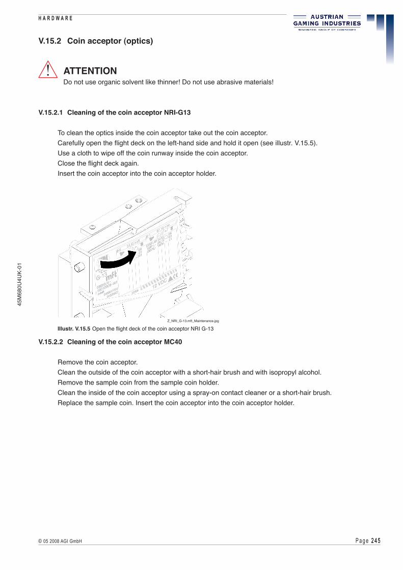
P a g e 2 4 5 2 4 5© 05 2008 AGI GmbH
H A R D W A R E45
M68
0U4U
K-01
V.15.2 Coin acceptor (optics)
ATTENTIONDo not use organic solvent like thinner! Do not use abrasive materials!
V.15.2.1 Cleaning of the coin acceptor NRI-G13
To clean the optics inside the coin acceptor take out the coin acceptor. Carefully open the flight deck on the left-hand side and hold it open (see illustr. V.15.5). Use a cloth to wipe off the coin runway inside the coin acceptor. Close the flight deck again. Insert the coin acceptor into the coin acceptor holder.
!
Z_NRI_G-13.mft_Maintenance.jpg
Illustr. V.15.5 Open the flight deck of the coin acceptor NRI G-13
V.15.2.2 Cleaning of the coin acceptor MC40
Remove the coin acceptor. Clean the outside of the coin acceptor with a short-hair brush and with isopropyl alcohol. Remove the sample coin from the sample coin holder. Clean the inside of the coin acceptor using a spray-on contact cleaner or a short-hair brush. Replace the sample coin. Insert the coin acceptor into the coin acceptor holder.

P a g e 2 4 6 2 4 6 © 05 2008 AGI GmbH
H A R D W A R E
45M
680U
4UK-
01
Recommended maintenance interval: 3-monthly
NOTE Make sure that the sensors are adjusted properly and that there are no obstructions in the optical transmission distance between the transmitter and the receiver.
V.15.3 Monitor / Touchscreen
DescriptionThe touchscreen should be cleaned at least once a week using a soft cloth and window cleaner. In addition, the touchscreen requires regular calibration, which will depend on how much it is used but should at least be done once a week ( see menu item CALIBRATION > TOUCH SCREEN CALIBRATION).When calibrating the touchscreen make sure that you are looking at the screen straight from above (from the player’s seated position) and that you are not touching the metal cabinet of the terminal with your body.
Recommended maintenance interval: weekly
F_Münzprüfer_ausgebaut.eps F_680CF2_MP_MC40.eps
Illustr. V.15.6 Coin optics board NRI-G13 Illustr. V.15.7 Coin optics board MC-40
V.15.2.3 Cleaning of the coin optics board
Open the fixing screws of the coin optics board. Clean the optics with a short-hair brush or a cottonbud and with isopropyl alcohol. Be careful not to bend the optics. Re-install the coin optics board.

P a g e 2 4 � 2 4 �© 05 2008 AGI GmbH
H A R D W A R E45
M68
0U4U
K-01
V.15.4 Ticket printer (print head)
Periodic cleaning operations will ensure continued high print quality from the printer.
Paper dust removal Use a soft brush to clean the paper dust from inside the printer and chassis area. The paper dust should also be removed from the sensor optics.
Cleaning print head If streaking on the printed ticket is evident, the print head may need to be cleaned. This can be done by inserting a thermal printer cleaning card.
1) Open the Printer Door. 2) Open the ticket cover and remove all tickets. 3) Close the ticket cover. 4) Insert the cleaning card into to the feed path. The cleaning card will automatically be drawn into the feed path. 5) Open the ticket cover and then remove the cleaning card by gently pulling it back. 6) Repeat process if necessary. 7) Proceed with ticket loading procedure (see part V.14.6).
Recommended maintenance interval: 3-monthly
V.15.5 Maintenance intervals
Machine part Interval
Bill acceptor monthly Coin acceptor 3-monthly Monitor / Touchscreen weekly Ticket printer (print head) 3-monthly

P a g e 2 4 8 2 4 8 © 05 2008 AGI GmbH
H A R D W A R E
45M
680U
4UK-
01

© 05 2008 AGI GmbHAustrian Gaming Industries GmbH
Wiener Strasse 158 . A-2352 Gumpoldskirchen . Austria . Europe . Tel.: +43-2252-606 . www.austrian-gaming.com . e-mail: [email protected]
45M
680U
4UK-
01
Annex
Table of Illustrations
EC-Declaration of Conformity
Glossary

P a g e 2 5 0 2 5 0 © 05 2008 AGI GmbH
A N N E X
45M
680U
4UK-
01

P a g e 2 5 1 2 5 1© 05 2008 AGI GmbH
A N N E X45
M68
0U4U
K-01
Table of Illustrations
Illustr. 0.1 ID Plate . . . . . . . . . . . . . . . . . . . . . . . . . . . . . . . . . . . . . . . . 2Illustr. I.1.1 Operating elements . . . . . . . . . . . . . . . . . . . . . . . . . . . . . . . . . . 9Illustr. I.2.1 Description of components . . . . . . . . . . . . . . . . . . . . . . . . . . . . . 10Illustr. I.3.1 Machine dimensions. . . . . . . . . . . . . . . . . . . . . . . . . . . . . . . . . 11Illustr. III.1.1 Main switch with fuses. . . . . . . . . . . . . . . . . . . . . . . . . . . . . . . . 23Illustr. III.2.1 Error display . . . . . . . . . . . . . . . . . . . . . . . . . . . . . . . . . . . . . 24Illustr. IV.1.1 Attendant keyswitch for error handling . . . . . . . . . . . . . . . . . . . . . . . 27Illustr. IV.1.2 Internal error - Screenshot . . . . . . . . . . . . . . . . . . . . . . . . . . . . . 28Illustr. IV.1.3 Error message - Explanation of elements . . . . . . . . . . . . . . . . . . . . . . 28Illustr. IV.9.1 Position of DIP switch 1 . . . . . . . . . . . . . . . . . . . . . . . . . . . . . . . 136Illustr. V.0.1 Description of components . . . . . . . . . . . . . . . . . . . . . . . . . . . . . 139Illustr. V.0.2 Block diagram . . . . . . . . . . . . . . . . . . . . . . . . . . . . . . . . . . . . 140Illustr. V.1.1 Dismounting of the switch module. . . . . . . . . . . . . . . . . . . . . . . . . . 144Illustr. V.1.2 Dismounting of the power distribution box . . . . . . . . . . . . . . . . . . . . . 145Illustr. V.1.3 Dismounting of the switching power supply . . . . . . . . . . . . . . . . . . . . . 146Illustr. V.2.1 Bill acceptor USB device . . . . . . . . . . . . . . . . . . . . . . . . . . . . . . 149Illustr. V.2.2 Exchange of the bill acceptor WBA-25-SS2. . . . . . . . . . . . . . . . . . . . . 150Illustr. V.2.3 Exchange of the bill acceptor Cashflow SC83 . . . . . . . . . . . . . . . . . . . 151Illustr. V.2.4 Components WBA-25-SS2 . . . . . . . . . . . . . . . . . . . . . . . . . . . . . 152Illustr. V.2.5 Components UBA . . . . . . . . . . . . . . . . . . . . . . . . . . . . . . . . . . 152Illustr. V.2.6 Components Cashflow SC83 . . . . . . . . . . . . . . . . . . . . . . . . . . . . 152Illustr. V.2.7 Components CashCode . . . . . . . . . . . . . . . . . . . . . . . . . . . . . . . 152Illustr. V.2.8 Collecting bills - WBA-25-SS2. . . . . . . . . . . . . . . . . . . . . . . . . . . . 153Illustr. V.2.9 Collecting bills - UBA . . . . . . . . . . . . . . . . . . . . . . . . . . . . . . . . 153Illustr. V.2.10 Collecting bills - Cashflow SC83 . . . . . . . . . . . . . . . . . . . . . . . . . . 154Illustr. V.2.11 Collecting bills - CashCode . . . . . . . . . . . . . . . . . . . . . . . . . . . . . 154Illustr. V.2.12 Removing jammed bills - WBA-25-SS2 . . . . . . . . . . . . . . . . . . . . . . . 155Illustr. V.2.13 Removing jammed bills - UBA. . . . . . . . . . . . . . . . . . . . . . . . . . . . 155Illustr. V.2.14 Removing jammed bills - Cashflow SC83 . . . . . . . . . . . . . . . . . . . . . . 156Illustr. V.2.15 Removing jammed bills - CashCode . . . . . . . . . . . . . . . . . . . . . . . . 156Illustr. V.2.16 Acceptor unit of the bill acceptor . . . . . . . . . . . . . . . . . . . . . . . . . . 157Illustr. V.3.1 Coin acceptor USB device . . . . . . . . . . . . . . . . . . . . . . . . . . . . . 161Illustr. V.3.2 Programming of the coin acceptor NRI-G13 . . . . . . . . . . . . . . . . . . . . 162Illustr. V.3.3 DIL switches on the coin acceptor. . . . . . . . . . . . . . . . . . . . . . . . . . 163Illustr. V.3.4 Switching block S1 - DIL switches. . . . . . . . . . . . . . . . . . . . . . . . . . 164Illustr. V.3.5 Switching block S2 - DIL switches. . . . . . . . . . . . . . . . . . . . . . . . . . 164Illustr. V.3.6 DIL witches (lower switching block) . . . . . . . . . . . . . . . . . . . . . . . . . 165Illustr. V.4.1 Hopper USB device . . . . . . . . . . . . . . . . . . . . . . . . . . . . . . . . . 169Illustr. V.4.2 Exchange of the hopper . . . . . . . . . . . . . . . . . . . . . . . . . . . . . . . 170Illustr. V.5.1 Position of the touchscreen controller . . . . . . . . . . . . . . . . . . . . . . . . 173Illustr. V.5.2 Dismounting of the lower monitor . . . . . . . . . . . . . . . . . . . . . . . . . . 174Illustr. V.5.3 Position of the upper monitor . . . . . . . . . . . . . . . . . . . . . . . . . . . . 175Illustr. V.5.4 Dismounting of the upper monitor . . . . . . . . . . . . . . . . . . . . . . . . . . 175Illustr. V.5.5 Exchange of the touchscreen controller . . . . . . . . . . . . . . . . . . . . . . . 176
P a g e 2 5 2 2 5 2 © 05 2008 AGI GmbH
A N N E X
45M
680U
4UK-
01
Illustr. V.6.1 Connectors and components of the COOLFIRE II motherboard . . . . . . . . . . 180Illustr. V.6.2 USB dongle (game selector) . . . . . . . . . . . . . . . . . . . . . . . . . . . . 181Illustr. V.6.3 Exchange of the main electronics COOLFIRE II . . . . . . . . . . . . . . . . . . 182Illustr. V.6.4 Correct insertion position of the EEPROM . . . . . . . . . . . . . . . . . . . . . 182Illustr. V.7.1 COOLFIRE II backplane connections . . . . . . . . . . . . . . . . . . . . . . . . 187Illustr. V.7.2 COOLFIRE II backplane fuses . . . . . . . . . . . . . . . . . . . . . . . . . . . 188Illustr. V.7.3 COOLFIRE II backplane position of the LEDs . . . . . . . . . . . . . . . . . . . 189Illustr. V.7.4 Exchange of the backplane . . . . . . . . . . . . . . . . . . . . . . . . . . . . . 198Illustr. V.8.1 Position of the key panel module . . . . . . . . . . . . . . . . . . . . . . . . . . 201Illustr. V.8.2 Connections of the key panel module . . . . . . . . . . . . . . . . . . . . . . . . 201Illustr. V.8.3 Exchange of the key panel module . . . . . . . . . . . . . . . . . . . . . . . . . 202Illustr. V.9.1 Dismounting of the upper monitor . . . . . . . . . . . . . . . . . . . . . . . . . . 205Illustr. V.9.2 Fixing screws of the top light in the lightbox . . . . . . . . . . . . . . . . . . . . 205Illustr. V.9.3 Components of the top light . . . . . . . . . . . . . . . . . . . . . . . . . . . . 206Illustr. V.10.1 Bill acceptor illumination . . . . . . . . . . . . . . . . . . . . . . . . . . . . . . . 209Illustr. V.10.2 Exchange of the bill acceptor illumination . . . . . . . . . . . . . . . . . . . . . . 209Illustr. V.10.3 Keyboard with illuminated button . . . . . . . . . . . . . . . . . . . . . . . . . . 210Illustr. V.10.4 Exchange of the key illumination . . . . . . . . . . . . . . . . . . . . . . . . . . 210Illustr. V.11.1 Position of the meters (front view). . . . . . . . . . . . . . . . . . . . . . . . . . 214Illustr. V.11.2 Fixing screws of the meters . . . . . . . . . . . . . . . . . . . . . . . . . . . . . 214Illustr. V.12.1 Door switch Top Large Door. . . . . . . . . . . . . . . . . . . . . . . . . . . . . 217Illustr. V.12.2 Door switch Front Large Door and Stacker Door . . . . . . . . . . . . . . . . . . 217Illustr. V.12.3 Door switch . . . . . . . . . . . . . . . . . . . . . . . . . . . . . . . . . . . . . 217Illustr. V.13.1 Volume control . . . . . . . . . . . . . . . . . . . . . . . . . . . . . . . . . . . . 221Illustr. V.13.2 Securing and locking lever . . . . . . . . . . . . . . . . . . . . . . . . . . . . . 222Illustr. V.13.3 Lightbox . . . . . . . . . . . . . . . . . . . . . . . . . . . . . . . . . . . . . . . 222Illustr. V.13.4 Exchange of the loudspeakers in the lightbox. . . . . . . . . . . . . . . . . . . . 222Illustr. V.13.5 Loudspeakers in the Drop Door . . . . . . . . . . . . . . . . . . . . . . . . . . . 223Illustr. V.14.1 Ticket printer in the bill acceptor hood. . . . . . . . . . . . . . . . . . . . . . . . 227Illustr. V.14.2 Printer Door, open . . . . . . . . . . . . . . . . . . . . . . . . . . . . . . . . . . 227Illustr. V.14.3 Unlocking of the ticket printer . . . . . . . . . . . . . . . . . . . . . . . . . . . . 228Illustr. V.14.4 Disassembly of the ticket printer . . . . . . . . . . . . . . . . . . . . . . . . . . 228Illustr. V.14.5 Removing loaded tickets - ITHACA EPIC 950 . . . . . . . . . . . . . . . . . . . 229Illustr. V.14.6 Removing loaded tickets - GEN2 Future Logic . . . . . . . . . . . . . . . . . . . 230Illustr. V.14.7 Loading tickets - ITHACA EPIC 950. . . . . . . . . . . . . . . . . . . . . . . . . 231Illustr. V.14.8 Loading tickets - GEN2 Future Logic . . . . . . . . . . . . . . . . . . . . . . . . 232Illustr. V.14.9 Status LED ITHACA EPIC 950 . . . . . . . . . . . . . . . . . . . . . . . . . . . 233Illustr. V.14.10 Status LED GEN2 Future Logic . . . . . . . . . . . . . . . . . . . . . . . . . . . 234Illustr. V.14.11 Firmware Upgrade ITHACA EPIC 950 . . . . . . . . . . . . . . . . . . . . . . . 235Illustr. V.15.1 Cleaning of bill acceptor WBA 25 . . . . . . . . . . . . . . . . . . . . . . . . . . 243Illustr. V.15.2 Cleaning of bill acceptor UBA . . . . . . . . . . . . . . . . . . . . . . . . . . . . 243Illustr. V.15.3 Cleaning of bill acceptor Cashflow . . . . . . . . . . . . . . . . . . . . . . . . . 243Illustr. V.15.4 Cleaning of bill acceptor CashCode. . . . . . . . . . . . . . . . . . . . . . . . . 243Illustr. V.15.5 Open the flight deck of the coin acceptor NRI G-13 . . . . . . . . . . . . . . . . 245Illustr. V.15.6 Coin optics board NRI-G13 . . . . . . . . . . . . . . . . . . . . . . . . . . . . . 246Illustr. V.15.7 Coin optics board MC-40 . . . . . . . . . . . . . . . . . . . . . . . . . . . . . . 246

P a g e 2 5 3 2 5 3© 05 2008 AGI GmbH
A N N E X45
M68
0U4U
K-01

P a g e 2 5 4 2 5 4 © 05 2008 AGI GmbH
A N N E X
45M
680U
4UK-
01
Glossary
B
Bill acceptor Device used for checking and collecting or denying banknotes or printed tickets.
Bill acceptor channel The bill acceptor has various software channels, which are used for recognition of different bills. Each channel is programmed for a single type of bill.
Booksize PC Personal computer in DIN A4 format. Manages all functions of the the machine. A keyboard can be connected for inputting data.
C
Calibration Function used to set the display precision for touchscreens.
Cancel Credit Equivalent to handpay. The credit is cancelled from the machine, and is paid out by the operator or attendant.
Coin channel The coin acceptor has various software channels, which are used for recognition of different coins. Each channel is programmed for a single type of coin.
D
DIP/DIL switch Dual in-line package switch; a number of microswitches on a bracket. Different settings are possible which depend on the position of the switches.
Dongle Special connector used as to copy-protected software.
G
Gamble Function Game function to double wins. This function is embedded in the game, and is accessed during present phases of the game.
Grounding strap Metallic, non-isolated cable, used to balance electric potentials.
H
Handpay Payout of wins or credits by an attendant or operator.
Hopper Coin dispenser; coins for payout of wins or credits are collected in the hopper

P a g e 2 5 5 2 5 5© 05 2008 AGI GmbH
A N N E X45
M68
0U4U
K-01
J
Jackpot Bets collected to a stock until a player reaches the win criteria.
K
Keycode Security code, used for repairs purposes.
L
LED Light Emitting Diode; light source based on semiconductor technique. Features high mechanical rigidity and an extremely long life.
M
Mechanical meters Mechanic device counting recurring actions, like coin insertions, remotes or wins.
P
Pin Connector, plug.
Power switching unit Unit supplying voltage to the logic unit of the machine.
Push up Book credit to a game. Carried out by the operator.
R
Reference coin The coin is used in the coin comparitor to check the validity of inserted coins.
Remote Function used to book credits.
Reset This function is used to clear the whole machine software. All bookkeeping statistics and all user-specific settings are cleared and set to Zero or to their default values.
ROM Abr. for: Read Only Memory; A type of memory that can be read but not written in normal operation. Special techniques are required to initialize the contents of a ROM, which are usually considered permanent and is powered by a small long-life battery.

P a g e 2 5 6 2 5 6 © 05 2008 AGI GmbH
A N N E X
45M
680U
4UK-
01
S
Sorter Coin deviator; depending on the position of the sorter, coins are collected in the hopper or in the cashbox.
Stand-by Sleeping mode, into which the machine changes when no game is being played.
T
Test switch Used for calling the Test Menu. The test switch is located inside the machine.
TFT Thin film transistor; a liquid crystal monitor. Every bitpoint is driven by a transistor. Best resolution results are obtained with TFT displays.
Ticket printer Printing unit, used for printing credit tickets, which can be used to cash wins or for moneyless payout purposes.
Token Credit coin, used instead of money during games.
Touchscreen Touch-sensitive monitor. Certain functions can be accessed by touching the buttons displayed directly on the monitor.
Z
Zapper error Suspicion of manipulation.

P a g e 2 5 �© 05 2008 AGI GmbH
F E E D B A C K F O R M45
M68
0U4U
K-01
Please spare some minutes of your time to answer the following questions as precisely as possibleand send the form back to us.You can reach us by phone under +43 2252 606 300, by fax under +43 2252 607 001. You can also send us an E-mail to [email protected].
YES NO1.) Were you satisfied with the execution of the order? c c
If “NO”, please indicate why.
2.) Have the machines been damaged during transport? c c
If “YES”, please indicate the damage.
3.) Were there any problems during the setting into operation c c
of the machine? If “YES”, please indicate.
4.) Are there any serious problems during the game operation? c c
If “YES”, please indicate.
5.) Are you satisfied with the software functions? c c
If “NO”, please indicate suggestions for improvement?
6.) Are you satisfied with the error handling? c c
If “NO”, please indicate suggestions for improvement?
7.) Are you satisfied with the cash handling? c c
If “NO”, please indicate suggestions for improvement?

P a g e 2 5 8 2 5 8 © 05 2008 AGI GmbH
F E E D B A C K F O R M
45M
680U
4UK-
01
YES NO8.) Do you think that the machine is user-optimized? c c
If “NO”, please indicate suggestions for improvement?
9.) Are you satisfied with the hardware? c c
If “NO”, please indicate suggestions for improvement?
10.) Are you satisfied with the spare parts supply? c c
If “NO”, please indicate why.
11.) Are you satisfied with our Technical Support? c c
If “NO”, please indicate why.
12.) Are our machines attractive for the players? c c
If “NO”, please indicate why.
13.) Other general suggestions for improvement: c c
Remitter:
Thank you!


![[XLS] · Web viewHommes Femmes ASD elenco KUOTA 01:00:44 01:00:55 01:01:17 01:01:20 01:01:39 01:02:47 01:03:02 01:04:37 01:08:33 01:08:37 01:09:09 01:11:17 01:13:43 01:18:49 01:28:33](https://img.pdfslide.net/doc/110x75/5af5f79b7f8b9a9e598ec483/xls-viewhommes-femmes-asd-elenco-kuota-010044-010055-010117-010120-010139.jpg)

![01 01 0 01 01 0 01 0 01 01 0 01 1 01 01 0 10 01 0 10 0 01 ...b[parent::TRF:a]/TRF-ANYSTEP::TRF:c XPathOptimizer XPath-Variants ranked XPath-Variants Timo Böhme 10 01 01 0 01 01 0](https://img.pdfslide.net/doc/110x75/5b37888f7f8b9a5f288e3298/01-01-0-01-01-0-01-0-01-01-0-01-1-01-01-0-10-01-0-10-0-01-bparenttrfatrf-anysteptrfc.jpg)