Embed Size (px)
Citation preview
Technical
Building over and adjacent to pipe assets
guidelines
October, 2015

Cover page: Better planning can prevent damage from heavy machinery working near pipelines.
SW269 04/15
Contents
1 Building over and adjacent 41.1 Overview 4
1.2 What are building over and adjacent (BOA) works? 4
1.3 What are Sydney Water pipe assets? 4
1.4 What are building works? 4
1.5 What pipes can you build over? 5
1.6 What pipes can you build adjacent to? 5
1.7 What is a service location diagram? 5
1.8 What is a service protection report? 5
1.9 What are building plans? 5
1.10 What is a specialist engineering assessment? 5
1.11 What are temporary protection works? 5
1.12 What are permanent protection works? 5
1.13 What is a monitoring plan? 6
1.14 What is a contingency plan? 6
1.15 What is the zone of influence? 6
2 Protecting pipe assets 72.1 Free and full access 7
2.2 Understanding the pipe asset 7
2.3 Temporary and permanent protection works 7
2.4 Maintenance-free concrete encasement 8
2.5 Reinforced concrete encasement 9
2.6 Lining 9
2.7 Bridging slab 9
2.8 Protecting pipe assets from construction plant loadings 10
3 BOA diagrams 133.1 General 13
3.2 Design responsibility 13
3.3 Approval 13
Diagram 1 – Demolition works 14
Diagram 2 – Building next to easements 15
Diagram 3 – Pavements on residential lots 16
Diagram 4 – Pavements on commercial or industrial lots 17
Diagram 5 – Planting trees 18
Diagram 6 – Lightweight structures over reticulation sewers 19
Diagram 7 – Working space around sewer maintenance structures 20
Diagram 8 – Building near free-standing ventshafts 21
Diagram 9 – Paling, chain-link and palisade fences 22
Diagram 10 – Short masonry walls 23
Diagram 11 – Retaining walls 24
Diagram 12 – Domestic stormwater absorption trenches 25
Diagram 13 – Domestic swimming pools / water tanks adjacent 26
Diagram 14 – Domestic swimming pools / water tanks over 27
Diagram 15 – Residential dwelling slabs and footings 28
Diagram 16 – Building foundations below the zone of influence 29
Diagram 17 – Building foundations on piles 30
Diagram 18 – Small unsupported excavations 31
Diagram 19 – Small supported excavations 32
Diagram 20 – Basement excavations 33
Diagram 21 – Dewatering 34
| 3Technical guidelines – Building over and adjacent to pipe assets
How to use these technical guidelines
Building over and adjacentSection 1 explains what are covered by the guidelines, what are building over and adjacent (BOA) works, and gives meaning to important terms used in the document.
Protecting pipe assetsSection 2 explains the notion of free and full access, and describes temporary and permanent works usually used to protect pipe assets. Some general guidance is also given for protecting our pipe assets from construction plant loadings.
BOA diagramsSection 3 contains diagrams illustrating common situations where works are built over and adjacent to our pipe assets. If your proposed works fit the depicted situation, the outlined technical requirements will apply. If your works do not fall under any of the situations, consult Sydney Water early and work with us to avoid damaging our assets.
ApprovalThis document does not tell you how to obtain approval from Sydney Water of your proposed works. Our Land development manual and Asset adjustment and protection manual will guide you through the approval procedure. You can find these documents at sydneywater.com.au.
4 | Technical guidelines – Building over and adjacent to pipe assets
1 Building over and adjacent
1.1 OverviewWhen you build over, adjacent, close to or under Sydney Water pipe assets, your work must not:
• obstruct full and free access to our assets
• cause physical damage to our assets
• weaken our assets leading to future damage.
This document outlines the technical requirements that apply in common building works. You may use these guidelines to understand whether your proposed building work is likely to cause adverse impacts. If you do not understand some of the complex technical issues, you must seek appropriate advice.
Our stormwater pipes and channels are not covered by this document. For information on stormwater assets refer to Guidelines for building over or adjacent to Sydney Water stormwater assets.
In addition to complying with the technical requirements, you must also obtain any stipulated approval, comply with the conditions of approval and exercise due care when you build. Our Land development manual and Asset adjustment and protection manual will guide you through the approval procedure. You can find these documents at sydneywater.com.au
These guidelines are to help you and your professional advisors including architects, engineers and designers to better plan and construct works that are near to our assets.
If you cause adverse impact to any of our assets, you will have to pay the costs of returning them to serviceable condition.
1.2 What are building over and adjacent (BOA) works?
Any building works likely to adversely impact on our pipe assets are regarded as ‘building over or adjacent to’ (BOA) works.
1.3 What are Sydney Water pipe assets?
Our pipe assets are buried or above-ground pipes and conduits of various size, shape and form. They were made of a variety of construction materials common at the time of construction. Some date back to the 19th century. Some pipes operate under internal pressure while others do not.
Some of our critical pipe assets are protected by acquired easements over land.
1.4 What are building works?Any new buildings and structures, or modification to existing buildings or structures, and any work that changes the current form and shape of the ground are ‘building works’.
Building works may include residential dwellings, commercial and industrial buildings, swimming pools, carports, non-habitable sheds, decks, fences, retaining walls, driveways, pavement, drains, landscaping, roads and infrastructure works.
Demolition of disused buildings and structures, temporary works and excavation works are also building works.
| 5Technical guidelines – Building over and adjacent to pipe assets
1.5 What pipes can you build over?
Sydney Water will consider allowing you to build certain structures over our reticulation sewers with diameters 300 mm and smaller.
Building over larger sewers, water and sewer pressure pipes is not preferred. If you wish to build over these pipes, talk to us early as we may impose substantial restrictions.
1.6 What pipes can you build adjacent to?
Sydney Water will allow you to build adjacent to our assets if you satisfy us that you will do all the necessary temporary and permanent works required to protect the assets from damage.
1.7 What is a service location diagram?
A service location diagram shows our pipe assets, but only indicates the presence of our pipes. It does not pinpoint the exact physical location.
The diagram is available from Sydney Water’s digitised mapping system HYDRA. You can also obtain them through the national referral service Dial Before You Dig.
1.8 What is a service protection report?
A service protection report identifies and pegs out on-site Sydney Water assets. It enables the accurate plotting of these assets onto your building plans. Only Sydney Water accredited personnel can prepare these reports.
1.9 What are building plans?Your building plans must describe in detail your proposed works and the location of Sydney Water pipe assets. If necessary, plans showing the extent and method of supporting excavation in the ground should be included. It may also include the construction sequence, dewatering or temporary works required during construction.
1.10 What is a specialist engineering assessment?
Where it is required, a specialist engineering assessment will include the following as applicable:
• The details of the proposed works.
• The construction methodology and sequence.
• The details of heavy construction equipment to be used in the construction, if any.
• The location, depth and as-constructed details of all Sydney Water pipe assets in the vicinity of the works.
• An appraisal of the existing condition of the pipe assets.
• An appraisal of the impact of the proposed permanent and temporary works on the pipe assets using the appropriate site investigation, engineering modelling or analysis method as necessary.
• The details of any temporary or permanent protection works required to safeguard the pipe from damage.
The assessment must be carried out by a Chartered Professional Engineer of the Institution of Engineers Australia with appropriate expertise and experience. The engineer must seek expert specialist advice such as geotechnical and other areas as required by the works.
1.11 What are temporary protection works?
Temporary protection works are those required to protect our pipe assets during your construction works. They may include supports, barriers or other construction control measures.
1.12 What are permanent protection works?
Permanent protection works are those required to be constructed to protect our pipe assets on a permanent basis. They may include strengthening or rehabilitation works and will remain after construction is complete.
6 | Technical guidelines – Building over and adjacent to pipe assets
1.13 What is a monitoring plan?A monitoring plan outlines how you will monitor the impact of your building works on our pipe assets. Your plan must contain warning thresholds to allow enough time to implement actions to avoid damage or failure of our assets. Your plan may also include dilapidation surveys.
1.14 What is a contingency plan?A contingency plan outlines the control measures that can reduce the consequences if your work causes our pipe asset to fail or disrupts our service to customers.
The plan may show alternative construction systems, provide for cut-off barriers or alternative construction equipment or change the sequence of work. It may also include providing emergency resources or repair materials, such as special pipe couplings or clamps.
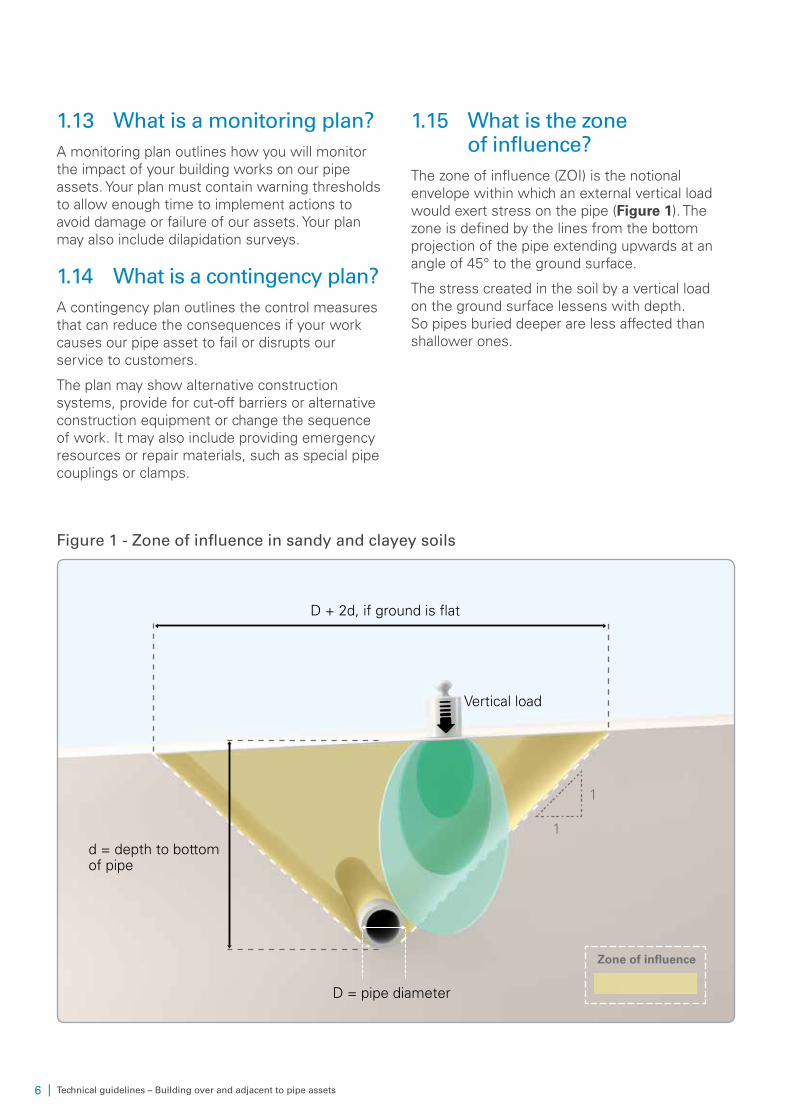
1.15 What is the zone of influence?
The zone of influence (ZOI) is the notional envelope within which an external vertical load would exert stress on the pipe (Figure 1). The zone is defined by the lines from the bottom projection of the pipe extending upwards at an angle of 45° to the ground surface.
The stress created in the soil by a vertical load on the ground surface lessens with depth. So pipes buried deeper are less affected than shallower ones.
Figure 1 - Zone of influence in sandy and clayey soils
D + 2d, if ground is flat
Vertical load
d = depth to bottom of pipe
D = pipe diameter
1
1
Zone of influence
| 7Technical guidelines – Building over and adjacent to pipe assets
2 Protecting pipe assets
2.1 Free and full access
2.1.1 General Sydney Water must be able to reach our pipe assets. Access to and working space around surface fittings and access points is required for routine operation and maintenance. We may also require construction and excavation space for repair or renewal.
Free access is safe 24-hour access so that incidents can be managed without delay. If your building works are likely to restrict free access hours and impede emergency response, you will need to make appropriate alternative access arrangements that must be agreed with and accepted by us.
Full access is required in the form of safe passageway for appropriate plant and equipment.
2.1.2 Reticulation sewer maintenance structures
For us to access reticulation sewer maintenance structures, we need an unobstructed passageway with a minimum width of 1 m and minimum clear headroom of 2.4 m. A maintenance vehicle must be able to park not more than 50 m from the maintenance structures.
To set a tripod at a maintenance hole, we need a working space of at least 1 m around the rim of the cover with minimum headroom of 2.4 m above. For a maintenance shaft, the working space may be reduced to 600 mm around the rim of the cover.
2.1.3 Other pipe assets Operating headroom clearance and working space requirements for other pipe assets vary according to asset type. It is important to consult Sydney Water early to obtain our specific requirements for your site.
Generally, minimum headroom of 2.8 m above pipe access points is required.
2.2 Understanding the pipe asset
Additional loadings, vibration or ground movement will increase stress in a pipe asset. This may compromise the built-in safety factor shortening service life and durability in the long-term. In severe cases, the increased stress could damage or collapse the pipe.
The ability to resist new loads depends on the type and existing service condition of the pipe asset. Older pipes with defects are more prone to damage than new ones. Lead-jointed cast iron pipes are vulnerable to damage by small ground movement. Sewer pipes corrode internally more severely than other pipes because of gases inside the pipe. Aggressive soil and groundwater attack the external protective coating of buried pipes.
If necessary, the service condition of an existing pipe asset is usually assessed by:
• CCTV inspection
• opening up the ground for visual inspection.
2.3 Temporary and permanent protection works
When BOA works are affecting our pipe asset, temporary or permanent protection works will be required. If pipe assets are built over, they may need to be strengthened or made more robust.
Temporary protection methods may include erecting temporary support or barriers, adapting construction methodology, and controlling vibration and ground movement.
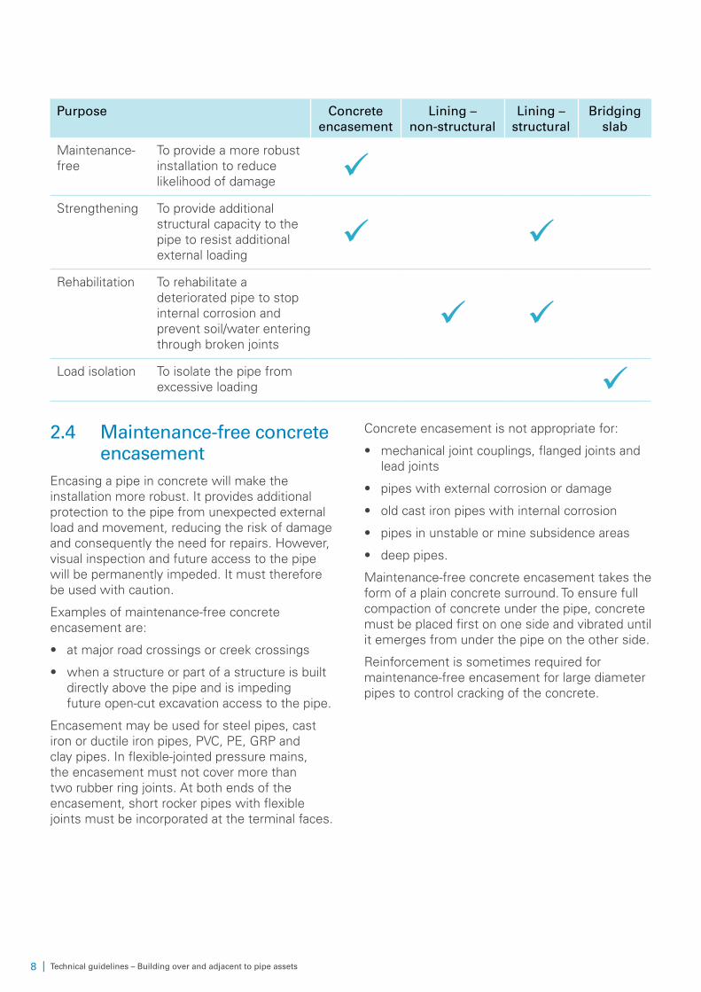
Permanent protection methods are typically concrete encasement, internal lining and bridging slabs. The table below explains when these methods are used.
8 | Technical guidelines – Building over and adjacent to pipe assets
Purpose Concrete encasement
Lining – non-structural
Lining – structural
Bridging slab
Maintenance-free
To provide a more robust installation to reduce likelihood of damage ü
Strengthening To provide additional structural capacity to the pipe to resist additional external loading
ü üRehabilitation To rehabilitate a
deteriorated pipe to stop internal corrosion and prevent soil/water entering through broken joints
ü üLoad isolation To isolate the pipe from
excessive loading ü2.4 Maintenance-free concrete
encasementEncasing a pipe in concrete will make the installation more robust. It provides additional protection to the pipe from unexpected external load and movement, reducing the risk of damage and consequently the need for repairs. However, visual inspection and future access to the pipe will be permanently impeded. It must therefore be used with caution.
Examples of maintenance-free concrete encasement are:
• at major road crossings or creek crossings
• when a structure or part of a structure is built directly above the pipe and is impeding future open-cut excavation access to the pipe.
Encasement may be used for steel pipes, cast iron or ductile iron pipes, PVC, PE, GRP and clay pipes. In flexible-jointed pressure mains, the encasement must not cover more than two rubber ring joints. At both ends of the encasement, short rocker pipes with flexible joints must be incorporated at the terminal faces.
Concrete encasement is not appropriate for:
• mechanical joint couplings, flanged joints and lead joints
• pipes with external corrosion or damage
• old cast iron pipes with internal corrosion
• pipes in unstable or mine subsidence areas
• deep pipes.
Maintenance-free concrete encasement takes the form of a plain concrete surround. To ensure full compaction of concrete under the pipe, concrete must be placed first on one side and vibrated until it emerges from under the pipe on the other side.
Reinforcement is sometimes required for maintenance-free encasement for large diameter pipes to control cracking of the concrete.
| 9Technical guidelines – Building over and adjacent to pipe assets
2.5 Reinforced concrete encasement
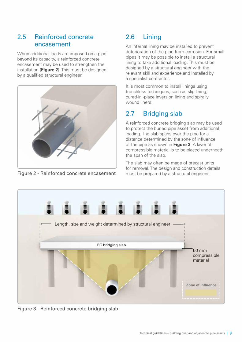
When additional loads are imposed on a pipe beyond its capacity, a reinforced concrete encasement may be used to strengthen the installation (Figure 2). This must be designed by a qualified structural engineer.
Figure 2 - Reinforced concrete encasement
2.6 LiningAn internal lining may be installed to prevent deterioration of the pipe from corrosion. For small pipes it may be possible to install a structural lining to take additional loading. This must be designed by a structural engineer with the relevant skill and experience and installed by a specialist contractor.
It is most common to install linings using trenchless techniques, such as slip lining, cured-in -place inversion lining and spirally wound liners.
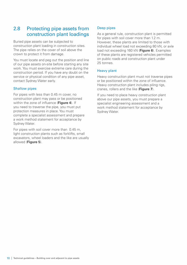
2.7 Bridging slabA reinforced concrete bridging slab may be used to protect the buried pipe asset from additional loading. The slab spans over the pipe for a distance determined by the zone of influence of the pipe as shown in Figure 3. A layer of compressible material is to be placed underneath the span of the slab.
The slab may often be made of precast units for removal. The design and construction details must be prepared by a structural engineer.
Length, size and weight determined by structural engineer
RC bridging slab
50 mm compressible material
Zone of influence
Figure 3 - Reinforced concrete bridging slab
10 | Technical guidelines – Building over and adjacent to pipe assets
2.8 Protecting pipe assets from construction plant loadings
Buried pipe assets can be subjected to construction plant loading in construction sites. The pipe relies on the cover of soil above the crown to protect it from damage.
You must locate and peg out the position and line of our pipe assets on-site before starting any site work. You must exercise extreme care during the construction period. If you have any doubt on the service or physical condition of any pipe asset, contact Sydney Water early.
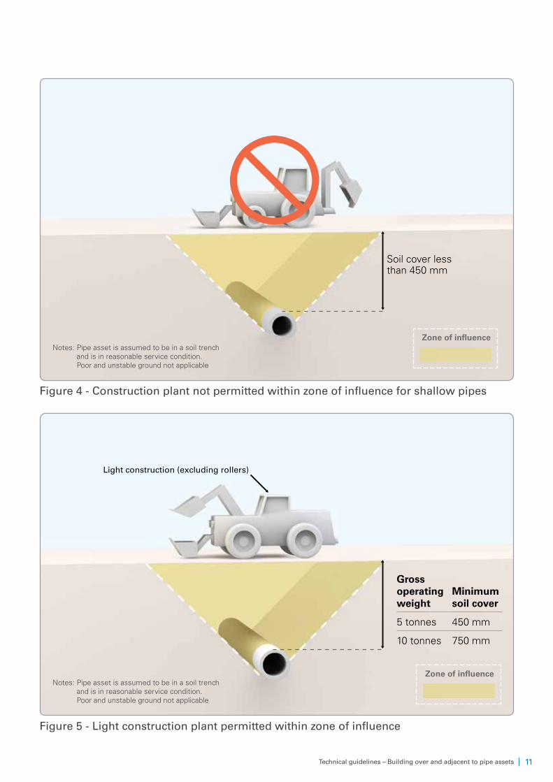
Shallow pipes
For pipes with less than 0.45 m cover, no construction plant may pass or be positioned within the zone of influence (Figure 4). If you need to traverse the pipe, you must put protection measures in place. You must complete a specialist assessment and prepare a work method statement for acceptance by Sydney Water.
For pipes with soil cover more than 0.45 m, light construction plants such as forklifts, small excavators, wheel loaders and the like are usually allowed (Figure 5).
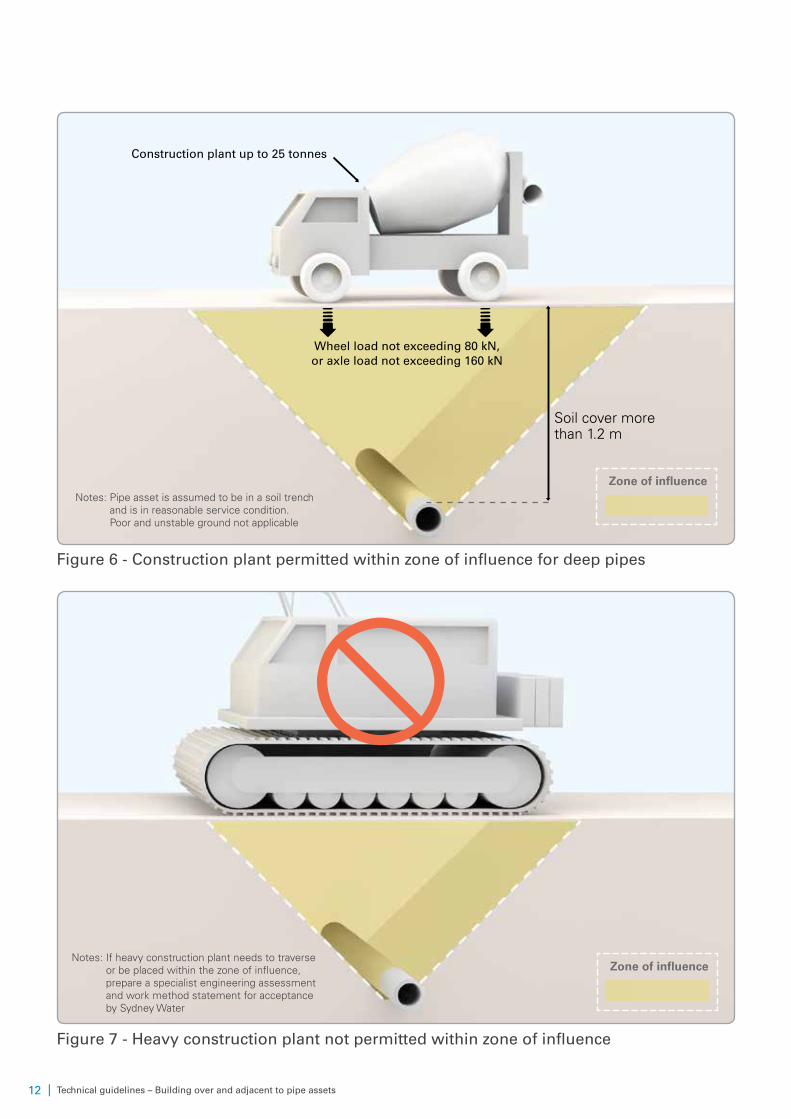
Deep pipes
As a general rule, construction plant is permitted for pipes with soil cover more than 1.2 m. However, these plants are limited to those with individual wheel load not exceeding 80 kN, or axle load not exceeding 160 kN (Figure 6). Examples of these plants are registered vehicles permitted on public roads and construction plant under 25 tonnes.
Heavy plant
Heavy construction plant must not traverse pipes or be positioned within the zone of influence. Heavy construction plant includes piling rigs, cranes, rollers and the like (Figure 7).
If you need to place heavy construction plant above our pipe assets, you must prepare a specialist engineering assessment and a work method statement for acceptance by Sydney Water.
| 11Technical guidelines – Building over and adjacent to pipe assets
Soil cover less than 450 mm
Zone of influence
Figure 4 - Construction plant not permitted within zone of influence for shallow pipes
Gross operating weight
Minimum soil cover
5 tonnes 450 mm
10 tonnes 750 mm
Light construction (excluding rollers)
Zone of influence
Figure 5 - Light construction plant permitted within zone of influence
Notes: Pipe asset is assumed to be in a soil trench and is in reasonable service condition. Poor and unstable ground not applicable
Notes: Pipe asset is assumed to be in a soil trench and is in reasonable service condition. Poor and unstable ground not applicable
12 | Technical guidelines – Building over and adjacent to pipe assets
Construction plant up to 25 tonnes
Wheel load not exceeding 80 kN, or axle load not exceeding 160 kN
Soil cover more than 1.2 m
Zone of influence
Figure 6 - Construction plant permitted within zone of influence for deep pipes
Zone of influence
Figure 7 - Heavy construction plant not permitted within zone of influence
Notes: Pipe asset is assumed to be in a soil trench and is in reasonable service condition. Poor and unstable ground not applicable
Notes: If heavy construction plant needs to traverse or be placed within the zone of influence, prepare a specialist engineering assessment and work method statement for acceptance by Sydney Water
| 13Technical guidelines – Building over and adjacent to pipe assets
3 BOA diagrams
3.1 GeneralYou may use these diagrams here to understand the technical requirements that will apply. The diagrams describe common situations where works are built over or adjacent to our pipe assets. These technical requirements are based on:
• usual ground condition – pipes were commonly laid in trench in sandy or clayey soils. When laid in rock trench, tunnels, poor or unstable grounds such as mine subsidence areas, special consideration and other requirements may apply.
• reasonable pipe service condition – pipe assets deteriorate over time. Those close to the end of their service life are more vulnerable to damage. Old cast iron and brick pipes are easily damaged by ground movement. When pipes are known to be vulnerable to damage, special consideration and requirements may apply.
If your building works do not fall under the situation described in these diagrams, consult Sydney Water early and work with us to avoid damaging our assets.
3.2 Design responsibilityThe design of your building works depends on site conditions and the method of construction. The designer must also comply with appropriate statutory requirements.
These diagrams inform you of the minimum requirements that Sydney Water will apply in dealing with BOA works. The stipulated requirements do not represent that any design work implied by the diagrams is adequate and sufficient. In no case do these diagrams lessen the designer’s responsibility to ensure the proposed works are fit for purpose for both your own use and in protecting our assets.
You must seek professional advice if you do not understand fully the intent of these diagrams. If you damage any of our assets, you will have to pay the costs of returning them to serviceable conditions.
3.3 ApprovalIn addition to complying with the technical requirements, you must also refer to our Land development manual and Asset adjustment and protection manual for guidance on how to obtain approval from Sydney Water.
14 | Technical guidelines – Building over and adjacent to pipe assets
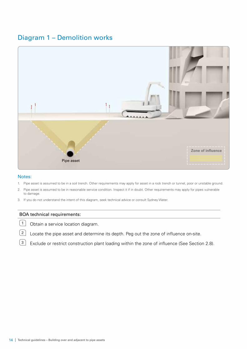
Diagram 1 – Demolition works
Pipe asset
Zone of influence
Notes:1. Pipe asset is assumed to be in a soil trench. Other requirements may apply for asset in a rock trench or tunnel, poor or unstable ground.
2. Pipe asset is assumed to be in reasonable service condition. Inspect it if in doubt. Other requirements may apply for pipes vulnerable to damage.
3. If you do not understand the intent of this diagram, seek technical advice or consult Sydney Water.
BOA technical requirements:
1 Obtain a service location diagram.
2 Locate the pipe asset and determine its depth. Peg out the zone of influence on-site.
3 Exclude or restrict construction plant loading within the zone of influence (See Section 2.8).
| 15Technical guidelines – Building over and adjacent to pipe assets
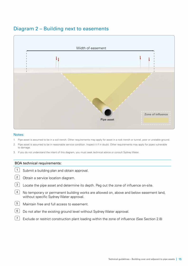
Diagram 2 – Building next to easements
Width of easement
Pipe asset
Zone of influence
Notes:1. Pipe asset is assumed to be in a soil trench. Other requirements may apply for asset in a rock trench or tunnel, poor or unstable ground.
2. Pipe asset is assumed to be in reasonable service condition. Inspect it if in doubt. Other requirements may apply for pipes vulnerable to damage.
3. If you do not understand the intent of this diagram, you must seek technical advice or consult Sydney Water.
BOA technical requirements:
1 Submit a building plan and obtain approval.
2 Obtain a service location diagram.
3 Locate the pipe asset and determine its depth. Peg out the zone of influence on-site.
4 No temporary or permanent building works are allowed on, above and below easement land, without specific Sydney Water approval.
5 Maintain free and full access to easement.
6 Do not alter the existing ground level without Sydney Water approval.
7 Exclude or restrict construction plant loading within the zone of influence (See Section 2.8)
16 | Technical guidelines – Building over and adjacent to pipe assets
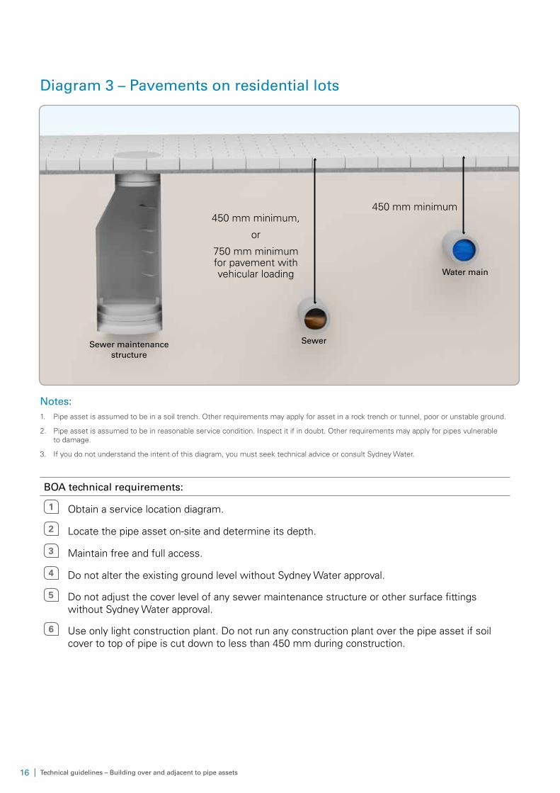
Diagram 3 – Pavements on residential lots
SewerSewer maintenance structure
Water main
450 mm minimum450 mm minimum,
or
750 mm minimum for pavement with vehicular loading
Notes:1. Pipe asset is assumed to be in a soil trench. Other requirements may apply for asset in a rock trench or tunnel, poor or unstable ground.
2. Pipe asset is assumed to be in reasonable service condition. Inspect it if in doubt. Other requirements may apply for pipes vulnerable to damage.
3. If you do not understand the intent of this diagram, you must seek technical advice or consult Sydney Water.
BOA technical requirements:
1 Obtain a service location diagram.
2 Locate the pipe asset on-site and determine its depth.
3 Maintain free and full access.
4 Do not alter the existing ground level without Sydney Water approval.
5 Do not adjust the cover level of any sewer maintenance structure or other surface fittings without Sydney Water approval.
6 Use only light construction plant. Do not run any construction plant over the pipe asset if soil cover to top of pipe is cut down to less than 450 mm during construction.
| 17Technical guidelines – Building over and adjacent to pipe assets
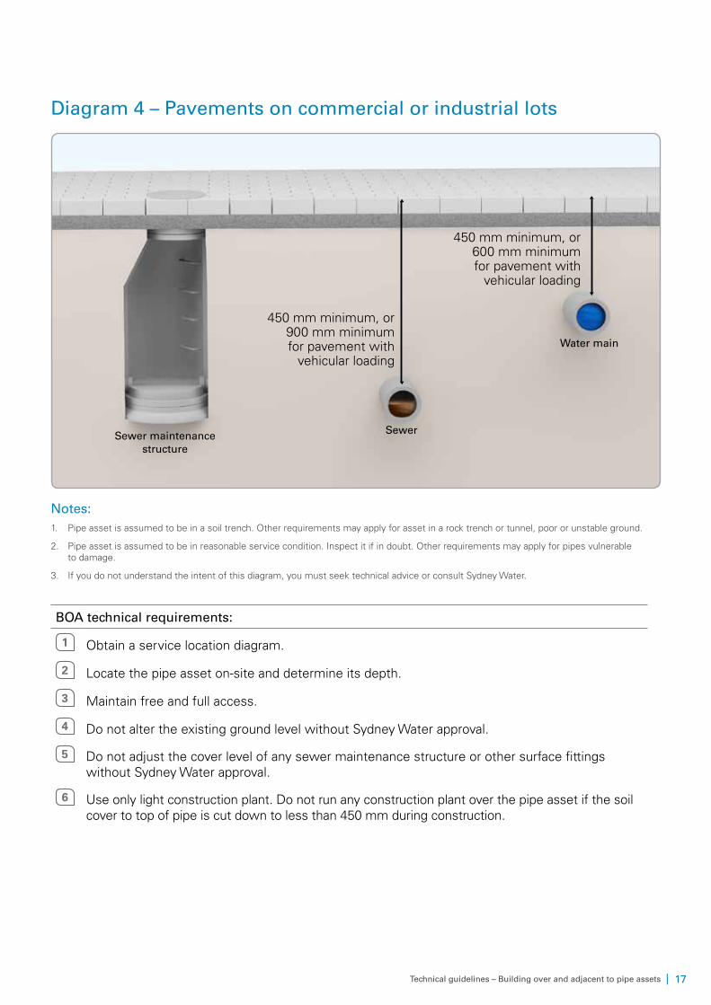
Diagram 4 – Pavements on commercial or industrial lots
Sewer maintenance structure
450 mm minimum, or 600 mm minimum for pavement with
vehicular loading
450 mm minimum, or 900 mm minimum for pavement with
vehicular loading
Sewer
Water main
Notes:1. Pipe asset is assumed to be in a soil trench. Other requirements may apply for asset in a rock trench or tunnel, poor or unstable ground.
2. Pipe asset is assumed to be in reasonable service condition. Inspect it if in doubt. Other requirements may apply for pipes vulnerable to damage.
3. If you do not understand the intent of this diagram, you must seek technical advice or consult Sydney Water.
BOA technical requirements:
1 Obtain a service location diagram.
2 Locate the pipe asset on-site and determine its depth.
3 Maintain free and full access.
4 Do not alter the existing ground level without Sydney Water approval.
5 Do not adjust the cover level of any sewer maintenance structure or other surface fittings without Sydney Water approval.
6 Use only light construction plant. Do not run any construction plant over the pipe asset if the soil cover to top of pipe is cut down to less than 450 mm during construction.

18 | Technical guidelines – Building over and adjacent to pipe assets
Diagram 5 – Planting trees
Root barrier Pipe asset
Not less than half drip line radius
Mature tree canopy drip
line radius
Note:If you do not understand the intent of this diagram, you must seek technical advice or consult Sydney Water.
BOA technical requirements:
1 Obtain a service location diagram.
2 Locate the pipe asset on-site and determine its depth.
3 Maintain free and full access.
4 Do not alter existing ground level without Sydney Water approval.
5 Consult Sydney Water or a tree specialist for suitable species and how far to plant them from pipe asset.
6 Do not plant trees closer than half the mature tree canopy drip line radius to the pipe.
7 Provide a tree root barrier if the pipe is under the future mature tree canopy. Install the barrier along the length of the pipe to the full extent of the canopy drip line.
| 19Technical guidelines – Building over and adjacent to pipe assets
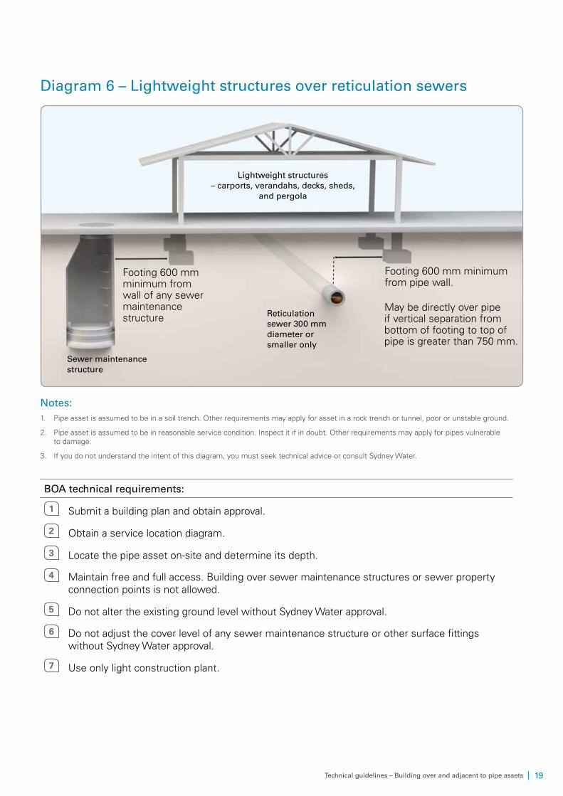
Diagram 6 – Lightweight structures over reticulation sewers
Footing 600 mm minimum from wall of any sewer maintenance structure
May be directly over pipe if vertical separation from bottom of footing to top of pipe is greater than 750 mm.
Lightweight structures – carports, verandahs, decks, sheds,
and pergola
Reticulation sewer 300 mm diameter or smaller only
Sewer maintenance structure
Footing 600 mm minimum from pipe wall.
Notes:1. Pipe asset is assumed to be in a soil trench. Other requirements may apply for asset in a rock trench or tunnel, poor or unstable ground.
2. Pipe asset is assumed to be in reasonable service condition. Inspect it if in doubt. Other requirements may apply for pipes vulnerable to damage.
3. If you do not understand the intent of this diagram, you must seek technical advice or consult Sydney Water.
BOA technical requirements:
1 Submit a building plan and obtain approval.
2 Obtain a service location diagram.
3 Locate the pipe asset on-site and determine its depth.
4 Maintain free and full access. Building over sewer maintenance structures or sewer property connection points is not allowed.
5 Do not alter the existing ground level without Sydney Water approval.
6 Do not adjust the cover level of any sewer maintenance structure or other surface fittings without Sydney Water approval.
7 Use only light construction plant.
20 | Technical guidelines – Building over and adjacent to pipe assets
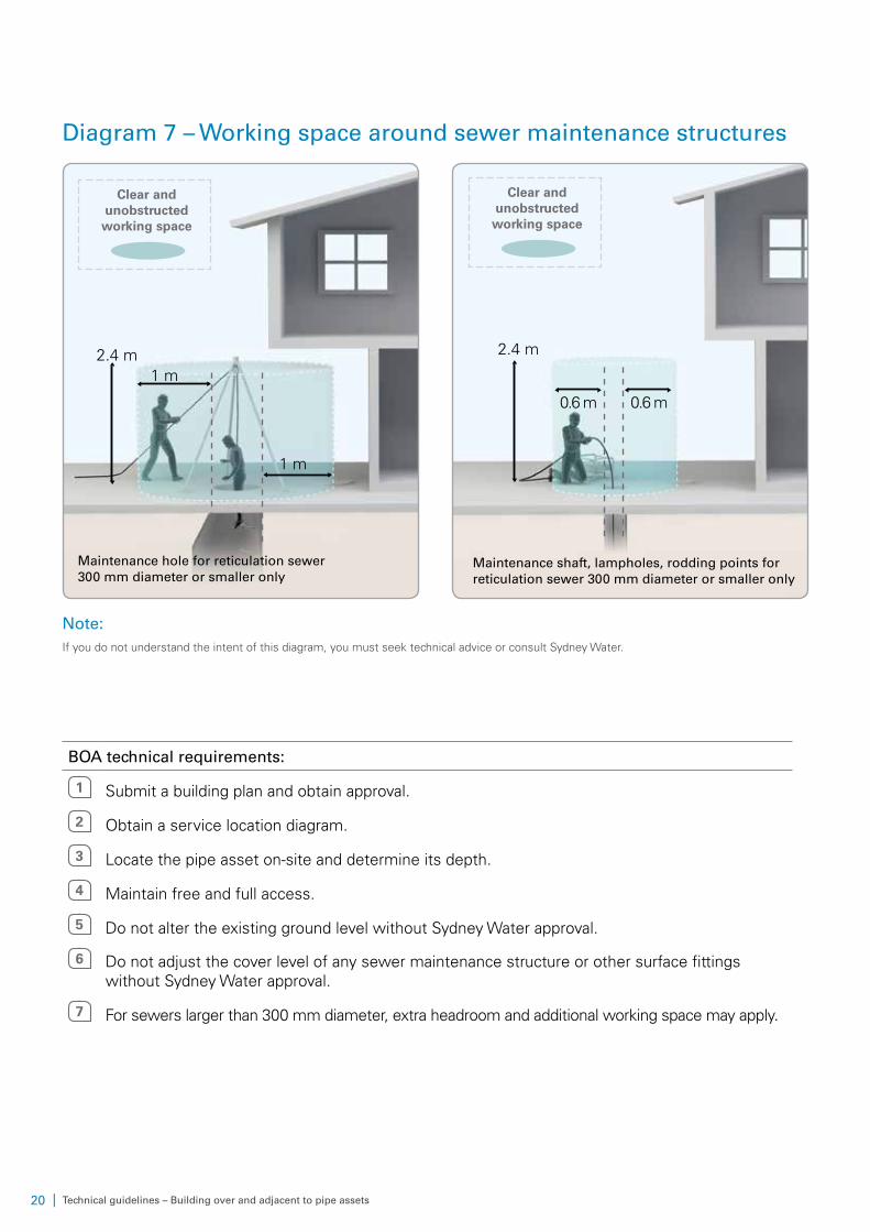
Diagram 7 – Working space around sewer maintenance structures
2.4 m1 m
1 m
Maintenance hole for reticulation sewer 300 mm diameter or smaller only
Clear and unobstructed
working space
Maintenance shaft, lampholes, rodding points for reticulation sewer 300 mm diameter or smaller only
2.4 m
0.6 m 0.6 m
Clear and unobstructed
working space
Note:If you do not understand the intent of this diagram, you must seek technical advice or consult Sydney Water.
BOA technical requirements:
1 Submit a building plan and obtain approval.
2 Obtain a service location diagram.
3 Locate the pipe asset on-site and determine its depth.
4 Maintain free and full access.
5 Do not alter the existing ground level without Sydney Water approval.
6 Do not adjust the cover level of any sewer maintenance structure or other surface fittings without Sydney Water approval.
7 For sewers larger than 300 mm diameter, extra headroom and additional working space may apply.

| 21Technical guidelines – Building over and adjacent to pipe assets
Diagram 8 – Building near free-standing ventshafts
free-standing ventshaft
2 m minimum unobstructed
working space
External wall
2 m minimum above eaves, windows and
air intakes
Note:If you are building close to any ventshaft, you must consult Sydney Water early.
BOA technical requirements:
1 Submit a building plan and obtain approval.
2 For ventshafts over 300 mm diameter, other requirements may apply.
3 Obtain a service location diagram.
4 Locate the pipe asset on-site.
5 Maintain free and full access.
6 Do not alter the existing ground level without Sydney Water approval.
7 Do not excavate near the ventshaft footing.
8 Erect a fence or barrier to protect the ventshaft from damage by construction plant.
22 | Technical guidelines – Building over and adjacent to pipe assets
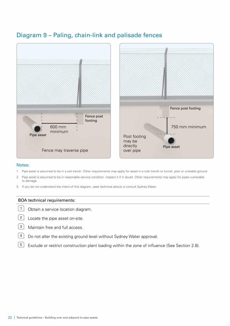
Diagram 9 – Paling, chain-link and palisade fences
Pipe asset
Fence may traverse pipe
600 mm minimum
Fence post footing
Fence post footing
750 mm minimum
Pipe asset
Post footing may be directly over pipe
Notes:1. Pipe asset is assumed to be in a soil trench. Other requirements may apply for asset in a rock trench or tunnel, poor or unstable ground.
2. Pipe asset is assumed to be in reasonable service condition. Inspect it if in doubt. Other requirements may apply for pipes vulnerable to damage.
3. If you do not understand the intent of this diagram, seek technical advice or consult Sydney Water.
BOA technical requirements:
1 Obtain a service location diagram.
2 Locate the pipe asset on-site.
3 Maintain free and full access.
4 Do not alter the existing ground level without Sydney Water approval.
5 Exclude or restrict construction plant loading within the zone of influence (See Section 2.8).
| 23Technical guidelines – Building over and adjacent to pipe assets
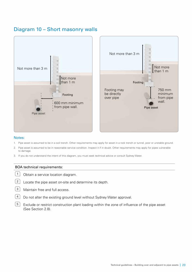
Diagram 10 – Short masonry walls
Footing
600 mm minimum from pipe wall.
Pipe asset
Not more than 3 m
Not more than 1 m Footing
Footing may be directly over pipe
Pipe asset
Not more than 3 m
750 mm minimum from pipe wall.
Not more than 1 m
Notes:1. Pipe asset is assumed to be in a soil trench. Other requirements may apply for asset in a rock trench or tunnel, poor or unstable ground.
2. Pipe asset is assumed to be in reasonable service condition. Inspect it if in doubt. Other requirements may apply for pipes vulnerable to damage.
3. If you do not understand the intent of this diagram, you must seek technical advice or consult Sydney Water.
BOA technical requirements:
1 Obtain a service location diagram.
2 Locate the pipe asset on-site and determine its depth.
3 Maintain free and full access.
4 Do not alter the existing ground level without Sydney Water approval.
5 Exclude or restrict construction plant loading within the zone of influence of the pipe asset (See Section 2.8).
24 | Technical guidelines – Building over and adjacent to pipe assets
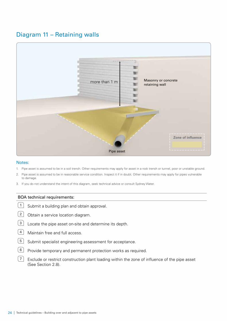
Diagram 11 – Retaining walls
Masonry or concrete retaining wall
more than 1 m
Zone of influence
Pipe asset
Notes:1. Pipe asset is assumed to be in a soil trench. Other requirements may apply for asset in a rock trench or tunnel, poor or unstable ground.
2. Pipe asset is assumed to be in reasonable service condition. Inspect it if in doubt. Other requirements may apply for pipes vulnerable to damage.
3. If you do not understand the intent of this diagram, seek technical advice or consult Sydney Water.
BOA technical requirements:
1 Submit a building plan and obtain approval.
2 Obtain a service location diagram.
3 Locate the pipe asset on-site and determine its depth.
4 Maintain free and full access.
5 Submit specialist engineering assessment for acceptance.
6 Provide temporary and permanent protection works as required.
7 Exclude or restrict construction plant loading within the zone of influence of the pipe asset (See Section 2.8).
| 25Technical guidelines – Building over and adjacent to pipe assets
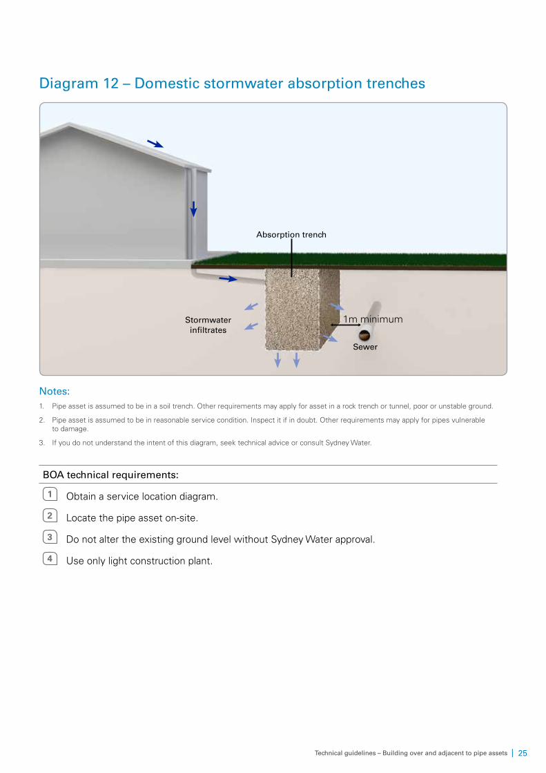
Diagram 12 – Domestic stormwater absorption trenches
Absorption trench
Stormwater infiltrates
Sewer
1m minimum
Notes:1. Pipe asset is assumed to be in a soil trench. Other requirements may apply for asset in a rock trench or tunnel, poor or unstable ground.
2. Pipe asset is assumed to be in reasonable service condition. Inspect it if in doubt. Other requirements may apply for pipes vulnerable to damage.
3. If you do not understand the intent of this diagram, seek technical advice or consult Sydney Water.
BOA technical requirements:
1 Obtain a service location diagram.
2 Locate the pipe asset on-site.
3 Do not alter the existing ground level without Sydney Water approval.
4 Use only light construction plant.
26 | Technical guidelines – Building over and adjacent to pipe assets
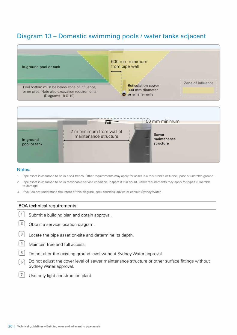
Diagram 13 – Domestic swimming pools / water tanks adjacent
Pool bottom must be below zone of influence, or on piles. Note also excavation requirements
(Diagrams 18 & 19).
In-ground pool or tank
Zone of influence
600 mm minimum from pipe wall
Reticulation sewer 300 mm diameter or smaller only
Sewer maintenance structure
2 m minimum from wall of maintenance structure
In-ground pool or tank
Fall 150 mm minimum
Notes:1. Pipe asset is assumed to be in a soil trench. Other requirements may apply for asset in a rock trench or tunnel, poor or unstable ground.
2. Pipe asset is assumed to be in reasonable service condition. Inspect it if in doubt. Other requirements may apply for pipes vulnerable to damage.
3. If you do not understand the intent of this diagram, seek technical advice or consult Sydney Water.
BOA technical requirements:
1 Submit a building plan and obtain approval.
2 Obtain a service location diagram.
3 Locate the pipe asset on-site and determine its depth.
4 Maintain free and full access.
5 Do not alter the existing ground level without Sydney Water approval.
6 Do not adjust the cover level of sewer maintenance structure or other surface fittings without Sydney Water approval.
7 Use only light construction plant.
| 27Technical guidelines – Building over and adjacent to pipe assets
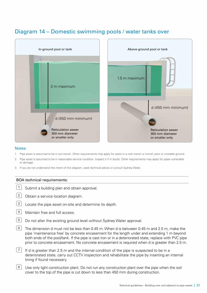
Diagram 14 – Domestic swimming pools / water tanks over
3 m maximum
In-ground pool or tank
d (450 mm minimum)
Reticulation sewer 300 mm diameter or smaller only
1.5 m maximum
Above-ground pool or tank
d (450 mm minimum)
Reticulation sewer 300 mm diameter or smaller only
Notes:1. Pipe asset is assumed to be in soil trench. Other requirements may apply for asset in a rock trench or tunnel, poor or unstable ground.
2. Pipe asset is assumed to be in reasonable service condition. Inspect it if in doubt. Other requirements may apply for pipes vulnerable to damage.
3. If you do not understand the intent of this diagram, seek technical advice or consult Sydney Water.
BOA technical requirements:
1 Submit a building plan and obtain approval.
2 Obtain a service location diagram.
3 Locate the pipe asset on-site and determine its depth.
4 Maintain free and full access.
5 Do not alter the existing ground level without Sydney Water approval.
6 The dimension d must not be less than 0.45 m. When d is between 0.45 m and 2.5 m, make the pipe ‘maintenance free’ by concrete encasement for the length under and extending 1 m beyond both ends of the pool/tank. If the pipe is cast iron or in a deteriorated state, replace with PVC pipe prior to concrete encasement. No concrete encasement is required when d is greater than 2.5 m.
7 If d is greater than 2.5 m and the internal condition of the pipe is suspected to be in a deteriorated state, carry out CCTV inspection and rehabilitate the pipe by inserting an internal lining if found necessary.
8 Use only light construction plant. Do not run any construction plant over the pipe when the soil cover to the top of the pipe is cut down to less than 450 mm during construction.
28 | Technical guidelines – Building over and adjacent to pipe assets
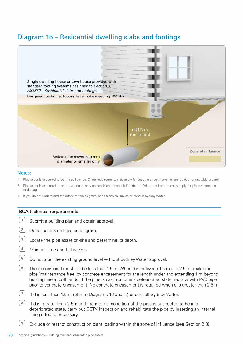
Diagram 15 – Residential dwelling slabs and footings
Reticulation sewer 300 mm diameter or smaller only
d (1.5 m minimum)
Single dwelling house or townhouse provided with standard footing systems designed to Section 3, AS2870 – Residential slabs and footings.
Desgined loading at footing level not exceeding 100 kPa
Zone of influence
Notes:1. Pipe asset is assumed to be in a soil trench. Other requirements may apply for asset in a rock trench or tunnel, poor or unstable ground.
2. Pipe asset is assumed to be in reasonable service condition. Inspect it if in doubt. Other requirements may apply for pipes vulnerable to damage.
3. If you do not understand the intent of this diagram, seek technical advice or consult Sydney Water.
BOA technical requirements:
1 Submit a building plan and obtain approval.
2 Obtain a service location diagram.
3 Locate the pipe asset on-site and determine its depth.
4 Maintain free and full access.
5 Do not alter the existing ground level without Sydney Water approval.
6 The dimension d must not be less than 1.5 m. When d is between 1.5 m and 2.5 m, make the pipe ‘maintenance free’ by concrete encasement for the length under and extending 1 m beyond building line at both ends. If the pipe is cast iron or in a deteriorated state, replace with PVC pipe prior to concrete encasement. No concrete encasement is required when d is greater than 2.5 m
7 If d is less than 1.5m, refer to Diagrams 16 and 17, or consult Sydney Water.
8 If d is greater than 2.5m and the internal condition of the pipe is suspected to be in a deteriorated state, carry out CCTV inspection and rehabilitate the pipe by inserting an internal lining if found necessary.
9 Exclude or restrict construction plant loading within the zone of influence (see Section 2.8).
| 29Technical guidelines – Building over and adjacent to pipe assets
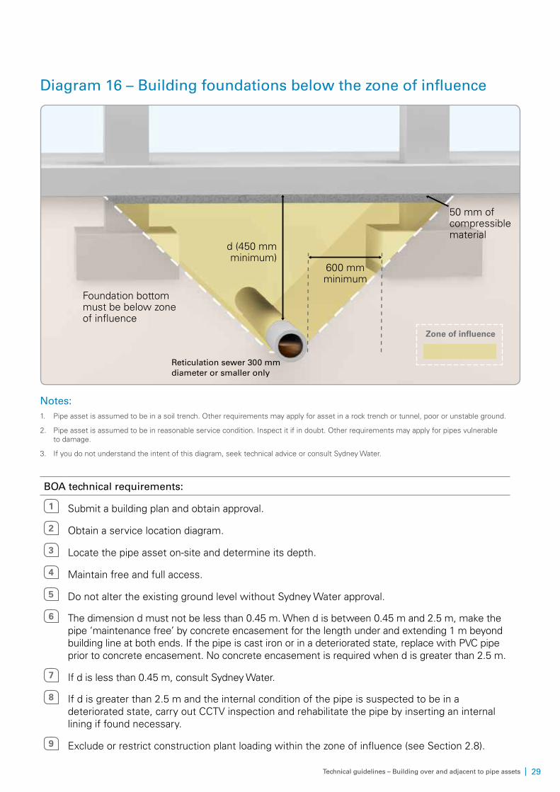
Diagram 16 – Building foundations below the zone of influence
Reticulation sewer 300 mm diameter or smaller only
600 mm minimum
d (450 mm minimum)
Foundation bottom must be below zone of influence
Zone of influence
50 mm of compressible material
Notes:1. Pipe asset is assumed to be in a soil trench. Other requirements may apply for asset in a rock trench or tunnel, poor or unstable ground.
2. Pipe asset is assumed to be in reasonable service condition. Inspect it if in doubt. Other requirements may apply for pipes vulnerable to damage.
3. If you do not understand the intent of this diagram, seek technical advice or consult Sydney Water.
BOA technical requirements:
1 Submit a building plan and obtain approval.
2 Obtain a service location diagram.
3 Locate the pipe asset on-site and determine its depth.
4 Maintain free and full access.
5 Do not alter the existing ground level without Sydney Water approval.
6 The dimension d must not be less than 0.45 m. When d is between 0.45 m and 2.5 m, make the pipe ‘maintenance free’ by concrete encasement for the length under and extending 1 m beyond building line at both ends. If the pipe is cast iron or in a deteriorated state, replace with PVC pipe prior to concrete encasement. No concrete encasement is required when d is greater than 2.5 m.
7 If d is less than 0.45 m, consult Sydney Water.
8 If d is greater than 2.5 m and the internal condition of the pipe is suspected to be in a deteriorated state, carry out CCTV inspection and rehabilitate the pipe by inserting an internal lining if found necessary.
9 Exclude or restrict construction plant loading within the zone of influence (see Section 2.8).
30 | Technical guidelines – Building over and adjacent to pipe assets
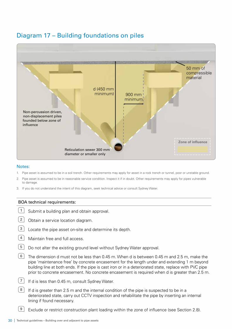
Diagram 17 – Building foundations on piles
Reticulation sewer 300 mm diameter or smaller only
Non-percussion driven, non-displacement piles founded below zone of influence
d (450 mm minimum) 900 mm
minimum
Zone of influence
50 mm of compressible material
Notes:1. Pipe asset is assumed to be in a soil trench. Other requirements may apply for asset in a rock trench or tunnel, poor or unstable ground.
2. Pipe asset is assumed to be in reasonable service condition. Inspect it if in doubt. Other requirements may apply for pipes vulnerable to damage.
3. If you do not understand the intent of this diagram, seek technical advice or consult Sydney Water.
BOA technical requirements:
1 Submit a building plan and obtain approval.
2 Obtain a service location diagram.
3 Locate the pipe asset on-site and determine its depth.
4 Maintain free and full access.
5 Do not alter the existing ground level without Sydney Water approval.
6 The dimension d must not be less than 0.45 m. When d is between 0.45 m and 2.5 m, make the pipe ‘maintenance free’ by concrete encasement for the length under and extending 1 m beyond building line at both ends. If the pipe is cast iron or in a deteriorated state, replace with PVC pipe prior to concrete encasement. No concrete encasement is required when d is greater than 2.5 m.
7 If d is less than 0.45 m, consult Sydney Water.
8 If d is greater than 2.5 m and the internal condition of the pipe is suspected to be in a deteriorated state, carry out CCTV inspection and rehabilitate the pipe by inserting an internal lining if found necessary.
9 Exclude or restrict construction plant loading within the zone of influence (see Section 2.8).
| 31Technical guidelines – Building over and adjacent to pipe assets
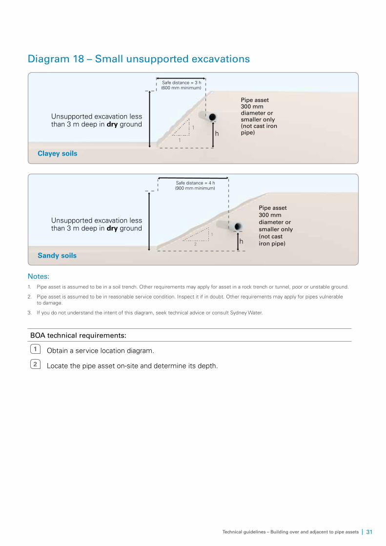
Diagram 18 – Small unsupported excavations
1
1
Clayey soils
Pipe asset 300 mm diameter or smaller only (not cast iron pipe)
Unsupported excavation less than 3 m deep in dry ground
h
Safe distance = 3 h (600 mm minimum)
Sandy soils
1
2
Pipe asset 300 mm diameter or smaller only (not cast iron pipe)
Unsupported excavation less than 3 m deep in dry ground
h
Safe distance = 4 h (900 mm minimum)
Notes:1. Pipe asset is assumed to be in a soil trench. Other requirements may apply for asset in a rock trench or tunnel, poor or unstable ground.
2. Pipe asset is assumed to be in reasonable service condition. Inspect it if in doubt. Other requirements may apply for pipes vulnerable to damage.
3. If you do not understand the intent of this diagram, seek technical advice or consult Sydney Water.
BOA technical requirements:
1 Obtain a service location diagram.
2 Locate the pipe asset on-site and determine its depth.
32 | Technical guidelines – Building over and adjacent to pipe assets
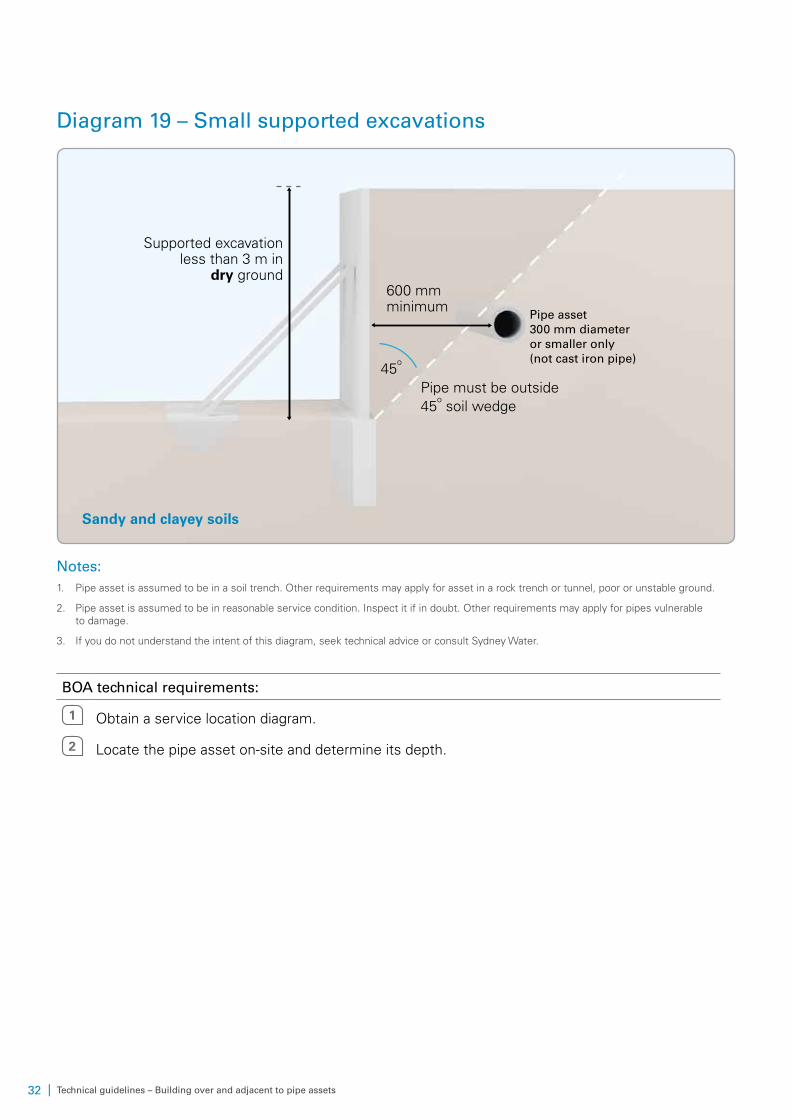
Diagram 19 – Small supported excavations
600 mm minimum
Pipe must be outside 45
o soil wedge
Pipe asset 300 mm diameter or smaller only (not cast iron pipe)
Supported excavation less than 3 m in
dry ground
Sandy and clayey soils
45o
Notes:1. Pipe asset is assumed to be in a soil trench. Other requirements may apply for asset in a rock trench or tunnel, poor or unstable ground.
2. Pipe asset is assumed to be in reasonable service condition. Inspect it if in doubt. Other requirements may apply for pipes vulnerable to damage.
3. If you do not understand the intent of this diagram, seek technical advice or consult Sydney Water.
BOA technical requirements:
1 Obtain a service location diagram.
2 Locate the pipe asset on-site and determine its depth.
| 33Technical guidelines – Building over and adjacent to pipe assets
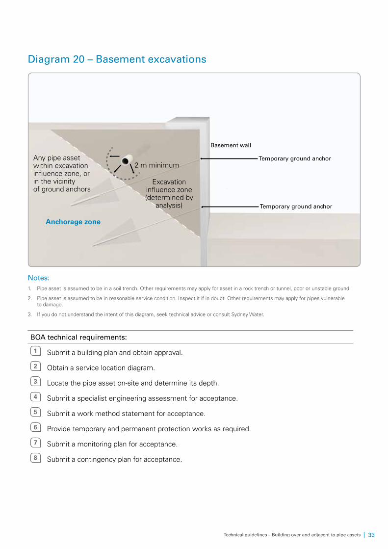
Diagram 20 – Basement excavations
Excavation influence zone (determined by
analysis)
Anchorage zone
Basement wall
Temporary ground anchor
Temporary ground anchorAny pipe asset within excavation influence zone, or in the vicinity of ground anchors
2 m minimum
Notes:1. Pipe asset is assumed to be in a soil trench. Other requirements may apply for asset in a rock trench or tunnel, poor or unstable ground.
2. Pipe asset is assumed to be in reasonable service condition. Inspect it if in doubt. Other requirements may apply for pipes vulnerable to damage.
3. If you do not understand the intent of this diagram, seek technical advice or consult Sydney Water.
BOA technical requirements:
1 Submit a building plan and obtain approval.
2 Obtain a service location diagram.
3 Locate the pipe asset on-site and determine its depth.
4 Submit a specialist engineering assessment for acceptance.
5 Submit a work method statement for acceptance.
6 Provide temporary and permanent protection works as required.
7 Submit a monitoring plan for acceptance.
8 Submit a contingency plan for acceptance.
34 | Technical guidelines – Building over and adjacent to pipe assets
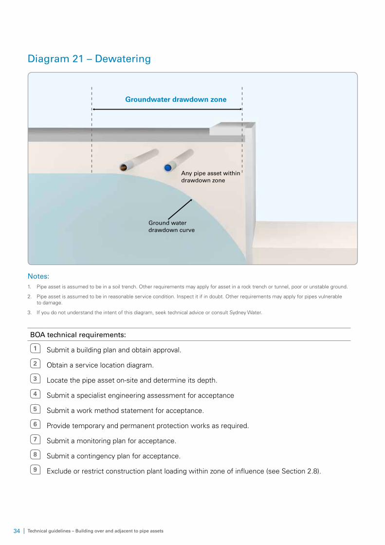
Diagram 21 – Dewatering
Ground water drawdown curve
Any pipe asset within drawdown zone
Groundwater drawdown zone
Notes:1. Pipe asset is assumed to be in a soil trench. Other requirements may apply for asset in a rock trench or tunnel, poor or unstable ground.
2. Pipe asset is assumed to be in reasonable service condition. Inspect it if in doubt. Other requirements may apply for pipes vulnerable to damage.
3. If you do not understand the intent of this diagram, seek technical advice or consult Sydney Water.
BOA technical requirements:
1 Submit a building plan and obtain approval.
2 Obtain a service location diagram.
3 Locate the pipe asset on-site and determine its depth.
4 Submit a specialist engineering assessment for acceptance
5 Submit a work method statement for acceptance.
6 Provide temporary and permanent protection works as required.
7 Submit a monitoring plan for acceptance.
8 Submit a contingency plan for acceptance.
9 Exclude or restrict construction plant loading within zone of influence (see Section 2.8).

| 35Technical guidelines – Building over and adjacent to pipe assets
4 Contact us
WebsiteVisit sydneywater.com.au
General enquiriesCall 13 20 92
Postal addressSydney Water PO Box 399 Parramatta NSW 2124