Embed Size (px)
Citation preview
1
4/8/16 CH
1080P AHD DVR
User’s Manual
V. 0.97
2
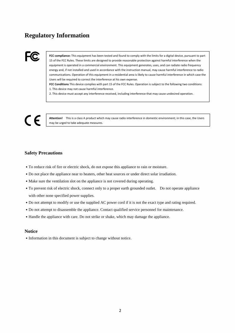
Regulatory Information
Safety Precautions
˙To reduce risk of fire or electric shock, do not expose this appliance to rain or moisture.
˙Do not place the appliance near to heaters, other heat sources or under direct solar irradiation.
˙Make sure the ventilation slot on the appliance is not covered during operating.
˙To prevent risk of electric shock, connect only to a proper earth grounded outlet. Do not operate appliance
with other none specified power supplies.
˙Do not attempt to modify or use the supplied AC power cord if it is not the exact type and rating required.
˙Do not attempt to disassemble the appliance. Contact qualified service personnel for maintenance.
˙Handle the appliance with care. Do not strike or shake, which may damage the appliance.
Notice
˙Information in this document is subject to change without notice.
FCC compliance: This equipment has been tested and found to comply with the limits for a digital device, pursuant to part
15 of the FCC Rules. These limits are designed to provide reasonable protection against harmful interference when the
equipment is operated in a commercial environment. This equipment generates, uses, and can radiate radio frequency
energy and, if not installed and used in accordance with the instruction manual, may cause harmful interference to radio
communications. Operation of this equipment in a residential area is likely to cause harmful interference in which case the
Users will be required to correct the interference at his own expense.
FCC Conditions This device complies with part 15 of the FCC Rules. Operation is subject to the following two conditions:
1. This device may not cause harmful interference.
2. This device must accept any interference received, including interference that may cause undesired operation.
Attention! This is a class A product which may cause radio interference in domestic environment; in this case, the Users
may be urged to take adequate measures.
3
TABLE OF CONTENTS
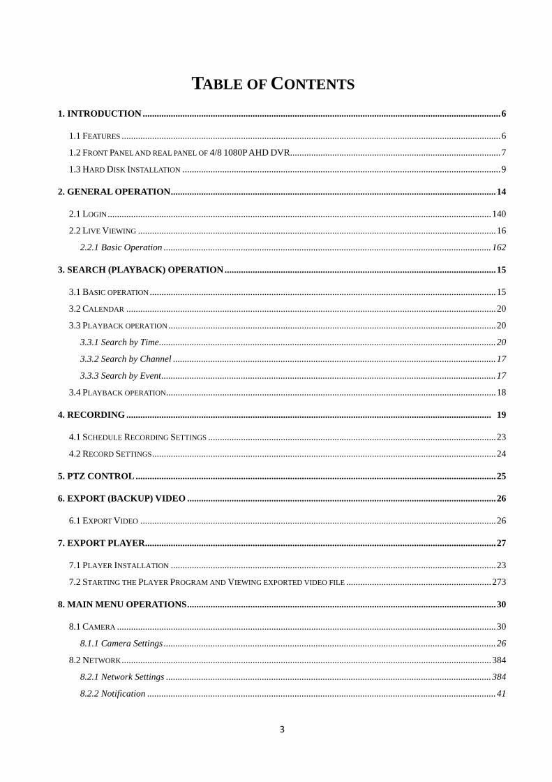
1. INTRODUCTION ......................................................................................................................................................... 6
1.1 FEATURES .................................................................................................................................................................. 6
1.2 FRONT PANEL AND REAL PANEL OF 4/8 1080P AHD DVR .......................................................................................... 7
1.3 HARD DISK INSTALLATION ........................................................................................................................................ 9
2. GENERAL OPERATION ........................................................................................................................................... 14
2.1 LOGIN .................................................................................................................................................................... 140
2.2 LIVE VIEWING ......................................................................................................................................................... 16
2.2.1 Basic Operation ............................................................................................................................................ 162
3. SEARCH (PLAYBACK) OPERATION .................................................................................................................... 15
3.1 BASIC OPERATION .................................................................................................................................................... 15
3.2 CALENDAR .............................................................................................................................................................. 20
3.3 PLAYBACK OPERATION ............................................................................................................................................ 20
3.3.1 Search by Time ................................................................................................................................................ 20
3.3.2 Search by Channel .......................................................................................................................................... 17
3.3.3 Search by Event ............................................................................................................................................... 17
3.4 PLAYBACK OPERATION ............................................................................................................................................. 18
4. RECORDING ............................................................................................................................................................ 19
4.1 SCHEDULE RECORDING SETTINGS ........................................................................................................................... 23
4.2 RECORD SETTINGS ................................................................................................................................................... 24
5. PTZ CONTROL .......................................................................................................................................................... 25
6. EXPORT (BACKUP) VIDEO .................................................................................................................................... 26
6.1 EXPORT VIDEO ........................................................................................................................................................ 26
7. EXPORT PLAYER ...................................................................................................................................................... 27
7.1 PLAYER INSTALLATION ........................................................................................................................................... 23
7.2 STARTING THE PLAYER PROGRAM AND VIEWING EXPORTED VIDEO FILE .............................................................. 273
8. MAIN MENU OPERATIONS .................................................................................................................................... 30
8.1 CAMERA .................................................................................................................................................................. 30
8.1.1 Camera Settings .............................................................................................................................................. 26
8.2 NETWORK .............................................................................................................................................................. 384
8.2.1 Network Settings ........................................................................................................................................... 384
8.2.2 Notification ..................................................................................................................................................... 41
4
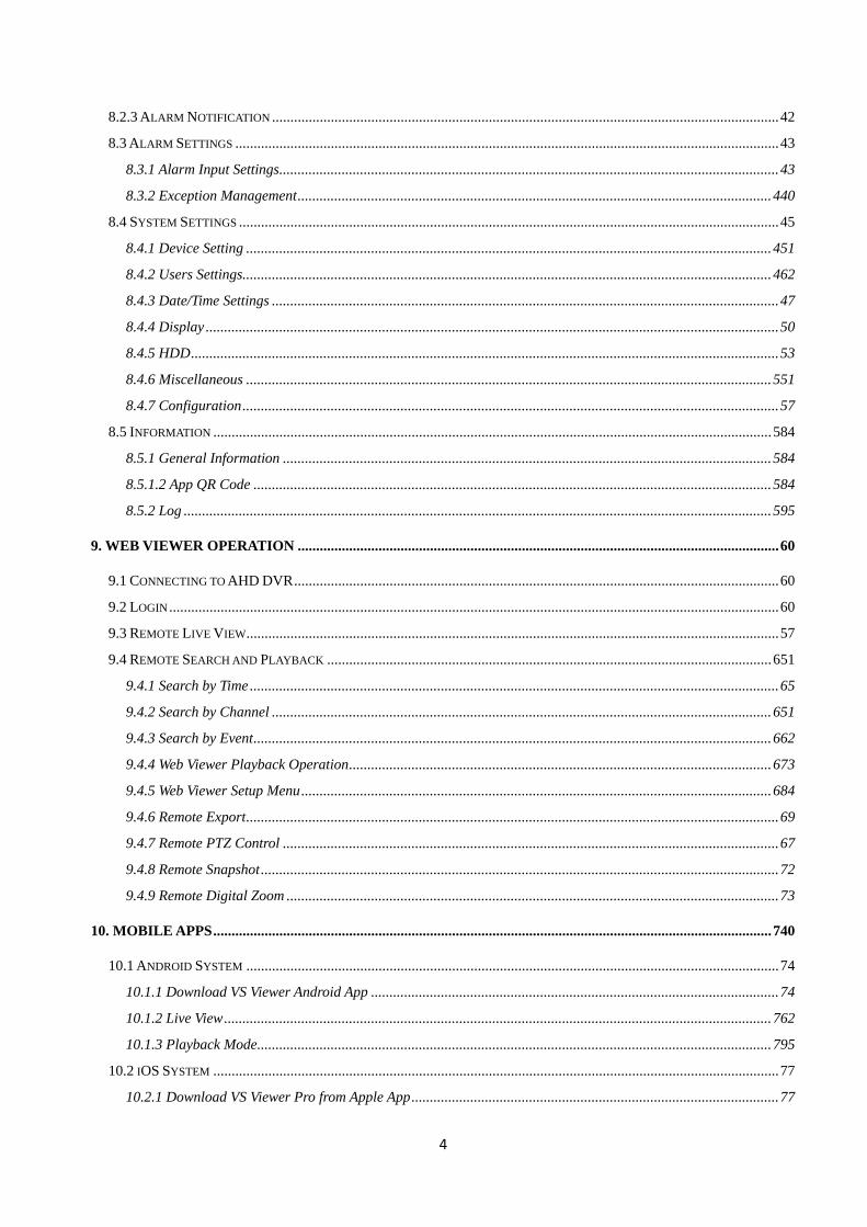
8.2.3 ALARM NOTIFICATION .......................................................................................................................................... 42
8.3 ALARM SETTINGS .................................................................................................................................................... 43
8.3.1 Alarm Input Settings ........................................................................................................................................ 43
8.3.2 Exception Management ................................................................................................................................. 440
8.4 SYSTEM SETTINGS ................................................................................................................................................... 45
8.4.1 Device Setting ............................................................................................................................................... 451
8.4.2 Users Settings................................................................................................................................................ 462
8.4.3 Date/Time Settings .......................................................................................................................................... 47
8.4.4 Display ............................................................................................................................................................ 50
8.4.5 HDD ................................................................................................................................................................ 53
8.4.6 Miscellaneous ............................................................................................................................................... 551
8.4.7 Configuration .................................................................................................................................................. 57
8.5 INFORMATION ........................................................................................................................................................ 584
8.5.1 General Information ..................................................................................................................................... 584
8.5.1.2 App QR Code ............................................................................................................................................. 584
8.5.2 Log ................................................................................................................................................................ 595
9. WEB VIEWER OPERATION ................................................................................................................................... 60
9.1 CONNECTING TO AHD DVR .................................................................................................................................... 60
9.2 LOGIN ...................................................................................................................................................................... 60
9.3 REMOTE LIVE VIEW ................................................................................................................................................. 57
9.4 REMOTE SEARCH AND PLAYBACK ......................................................................................................................... 651
9.4.1 Search by Time ................................................................................................................................................ 65
9.4.2 Search by Channel ........................................................................................................................................ 651
9.4.3 Search by Event ............................................................................................................................................. 662
9.4.4 Web Viewer Playback Operation ................................................................................................................... 673
9.4.5 Web Viewer Setup Menu ................................................................................................................................ 684
9.4.6 Remote Export ................................................................................................................................................. 69
9.4.7 Remote PTZ Control ....................................................................................................................................... 67
9.4.8 Remote Snapshot ............................................................................................................................................. 72
9.4.9 Remote Digital Zoom ...................................................................................................................................... 73
10. MOBILE APPS ........................................................................................................................................................ 740
10.1 ANDROID SYSTEM ................................................................................................................................................. 74
10.1.1 Download VS Viewer Android App ............................................................................................................... 74
10.1.2 Live View ..................................................................................................................................................... 762
10.1.3 Playback Mode ............................................................................................................................................ 795
10.2 IOS SYSTEM .......................................................................................................................................................... 77
10.2.1 Download VS Viewer Pro from Apple App .................................................................................................... 77
5
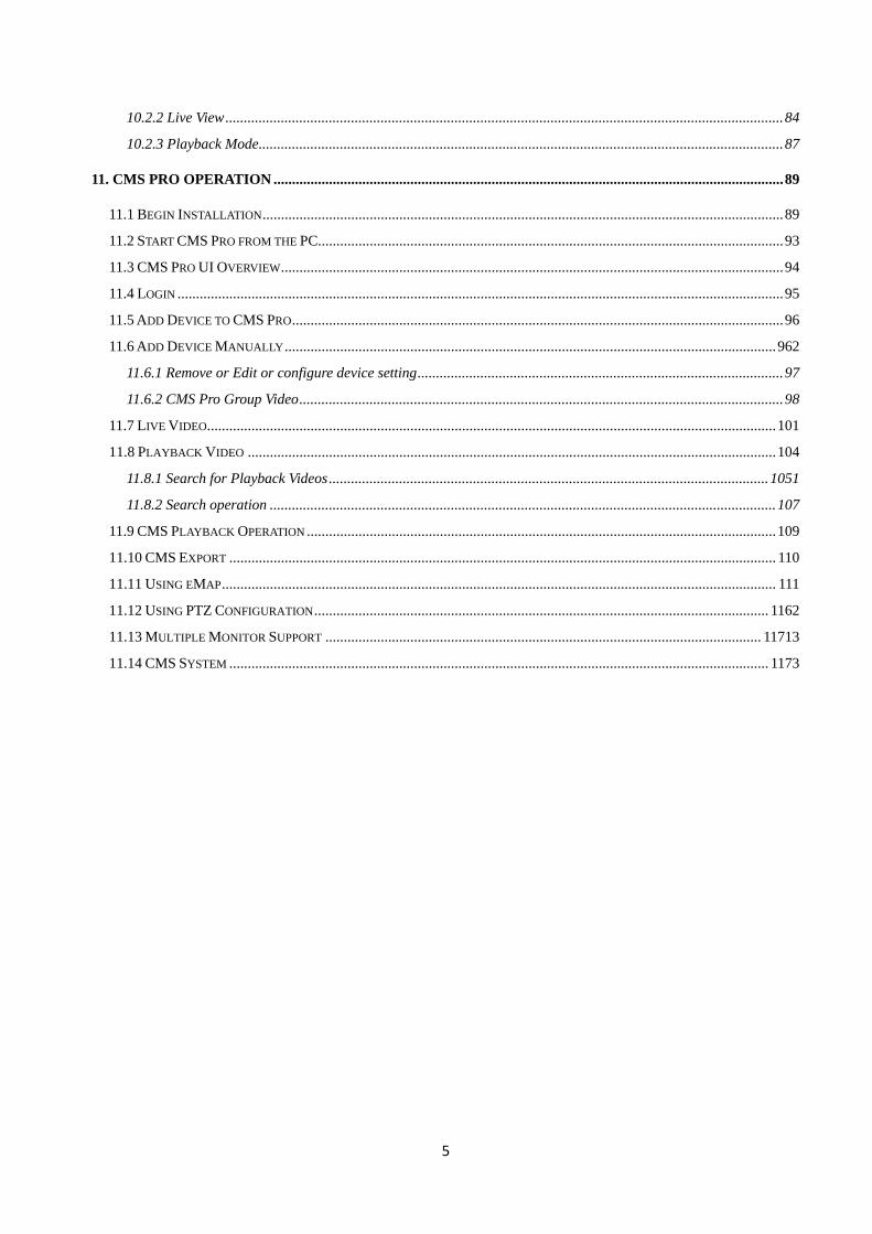
10.2.2 Live View ....................................................................................................................................................... 84
10.2.3 Playback Mode .............................................................................................................................................. 87
11. CMS PRO OPERATION .......................................................................................................................................... 89
11.1 BEGIN INSTALLATION ............................................................................................................................................. 89
11.2 START CMS PRO FROM THE PC.............................................................................................................................. 93
11.3 CMS PRO UI OVERVIEW ........................................................................................................................................ 94
11.4 LOGIN .................................................................................................................................................................... 95
11.5 ADD DEVICE TO CMS PRO ..................................................................................................................................... 96
11.6 ADD DEVICE MANUALLY ..................................................................................................................................... 962
11.6.1 Remove or Edit or configure device setting ................................................................................................... 97
11.6.2 CMS Pro Group Video ................................................................................................................................... 98
11.7 LIVE VIDEO .......................................................................................................................................................... 101
11.8 PLAYBACK VIDEO ............................................................................................................................................... 104
11.8.1 Search for Playback Videos ....................................................................................................................... 1051
11.8.2 Search operation ......................................................................................................................................... 107
11.9 CMS PLAYBACK OPERATION ............................................................................................................................... 109
11.10 CMS EXPORT .................................................................................................................................................... 110
11.11 USING EMAP ...................................................................................................................................................... 111
11.12 USING PTZ CONFIGURATION ........................................................................................................................... 1162
11.13 MULTIPLE MONITOR SUPPORT ...................................................................................................................... 11713
11.14 CMS SYSTEM .................................................................................................................................................. 1173
6
1. Introduction
The 4/8/16 CH 1080P AHD DVR transmits Full HD (1080P) / 720P or Analog video image
over coaxial cables. It performs the high definition image with zero loss and low latency of
image data when viewing the video. The AHD DVR provides the easy-to-install benefit that
allows users to view the HD megapixel image without requiring having the complicated
knowledge of IP based system. It is the ultimate solution for high-quality and reliable
surveillance system.
1.1 Features
AHD 1080P DVR supports AHD 1080P/720P/Analog cameras Tribrid seamless
inputs
Dual -Core CPU demonstrates the extreme and industry-leading performance in recording,
playback and networking
Support maximum up to 240fps recording with 1080p30 of each channel
AHD 1080P 15fps Models 4/8/16CH support max.60/120/240fps; 15fps/per channel.
AHD 1080P 30fps Models 4/8/16CH support max.120/240/480fps; 30fps/per channel.
Dual stream support for remote access from a PC and/or a cell phone at low bandwidth
Programmable dual monitor
Bi-directional audio
Remote access through Web, CMS, Mobile App (Android & iOS)
Easy data export via USB drive, webpage and USB external HDD
Search control by date/time, alarm, channel search
Free bundle CMS for multiple device management
Free DDNS server provided for Dynamic IP address
7
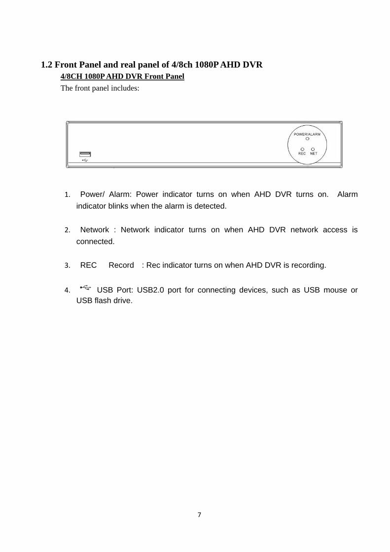
1.2 Front Panel and real panel of 4/8ch 1080P AHD DVR
4/8CH 1080P AHD DVR Front Panel
The front panel includes:
1. Power/ Alarm: Power indicator turns on when AHD DVR turns on. Alarm
indicator blinks when the alarm is detected.
2. Network : Network indicator turns on when AHD DVR network access is
connected.
3. REC Record : Rec indicator turns on when AHD DVR is recording.
4. USB Port: USB2.0 port for connecting devices, such as USB mouse or
USB flash drive.
8
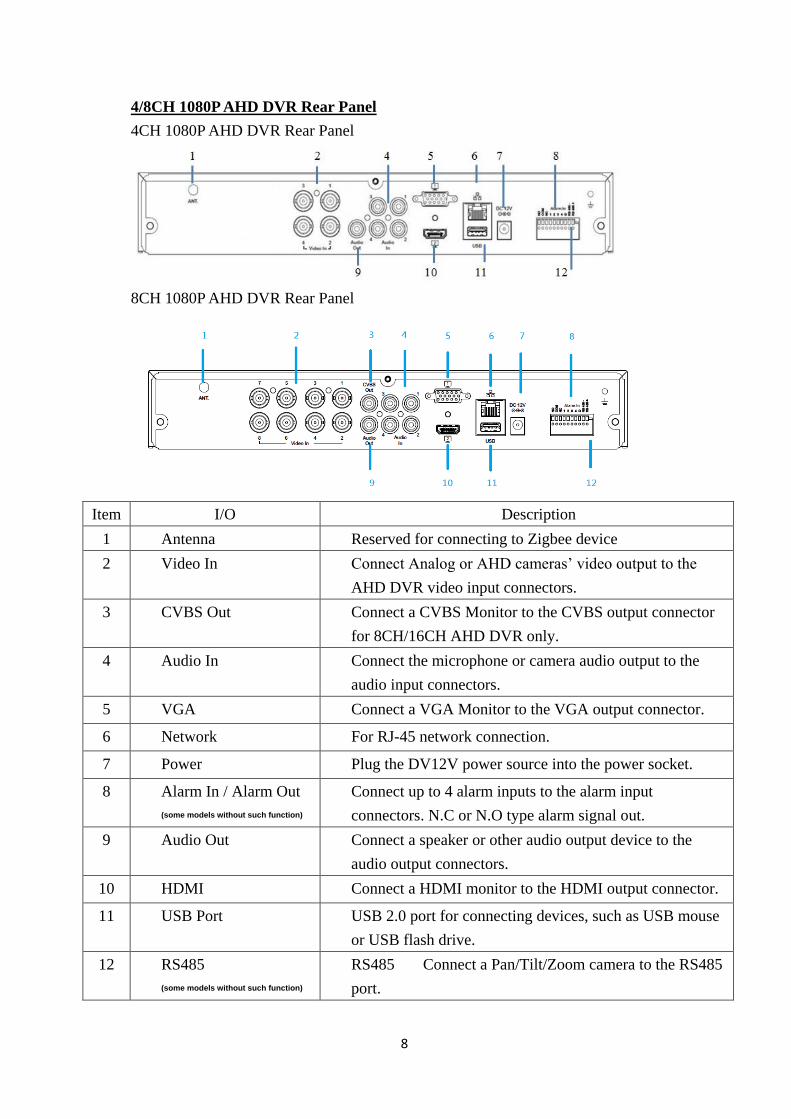
4/8CH 1080P AHD DVR Rear Panel
4CH 1080P AHD DVR Rear Panel
8CH 1080P AHD DVR Rear Panel
Item I/O Description
1 Antenna Reserved for connecting to Zigbee device
2 Video In Connect Analog or AHD cameras’ video output to the
AHD DVR video input connectors.
3 CVBS Out Connect a CVBS Monitor to the CVBS output connector
for 8CH/16CH AHD DVR only.
4 Audio In Connect the microphone or camera audio output to the
audio input connectors.
5 VGA Connect a VGA Monitor to the VGA output connector.
6 Network For RJ-45 network connection.
7 Power Plug the DV12V power source into the power socket.
8 Alarm In / Alarm Out
(some models without such function)
Connect up to 4 alarm inputs to the alarm input
connectors. N.C or N.O type alarm signal out.
9 Audio Out Connect a speaker or other audio output device to the
audio output connectors.
10 HDMI Connect a HDMI monitor to the HDMI output connector.
11 USB Port USB 2.0 port for connecting devices, such as USB mouse
or USB flash drive.
12 RS485
(some models without such function)
RS485 Connect a Pan/Tilt/Zoom camera to the RS485
port.
9
4/8CH AHD DVR Packing Content
The package contains the following items:
-AHD DVR x 1 -User manual/Quick Install/CMS disc x 1
-Quick Install Paper x1 -Power adapter x 1
-SATA connection cable x 2 -Screws for mounting hard drive x 8 pcs
(Enclose one set SATA & Power wire for one HDD models)
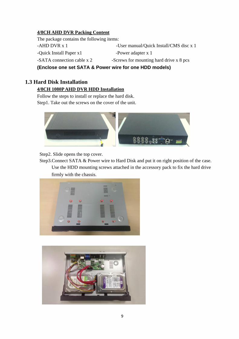
1.3 Hard Disk Installation
4/8CH 1080P AHD DVR HDD Installation
Follow the steps to install or replace the hard disk.
Step1. Take out the screws on the cover of the unit.
Step2. Slide opens the top cover.
Step3.Connect SATA & Power wire to Hard Disk and put it on right position of the case.
Use the HDD mounting screws attached in the accessory pack to fix the hard drive
firmly with the chassis.
10
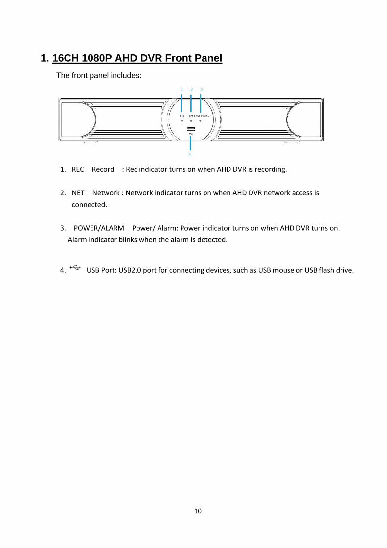
1. 16CH 1080P AHD DVR Front Panel
The front panel includes:
1. REC Record : Rec indicator turns on when AHD DVR is recording.
2. NET Network : Network indicator turns on when AHD DVR network access is
connected.
3. POWER/ALARM Power/ Alarm: Power indicator turns on when AHD DVR turns on.
Alarm indicator blinks when the alarm is detected.
4. USB Port: USB2.0 port for connecting devices, such as USB mouse or USB flash drive.
11
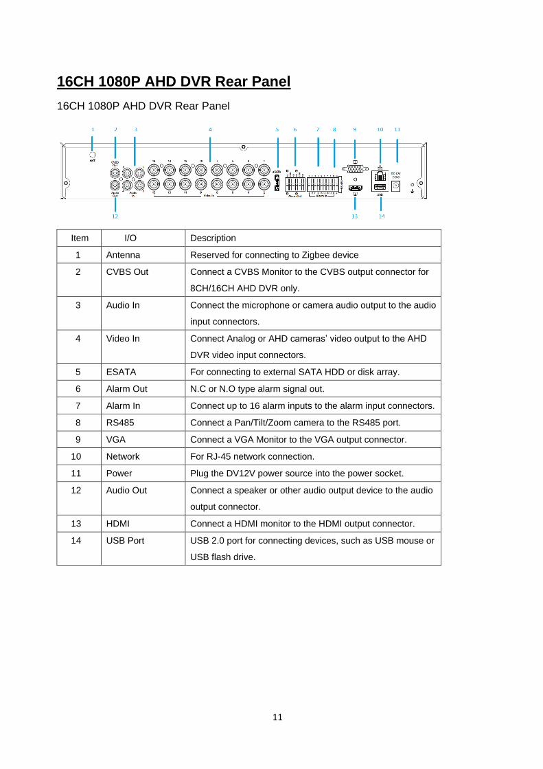
16CH 1080P AHD DVR Rear Panel
16CH 1080P AHD DVR Rear Panel
Item I/O Description
1 Antenna Reserved for connecting to Zigbee device
2 CVBS Out Connect a CVBS Monitor to the CVBS output connector for
8CH/16CH AHD DVR only.
3 Audio In Connect the microphone or camera audio output to the audio
input connectors.
4 Video In Connect Analog or AHD cameras’ video output to the AHD
DVR video input connectors.
5 ESATA For connecting to external SATA HDD or disk array.
6 Alarm Out N.C or N.O type alarm signal out.
7 Alarm In Connect up to 16 alarm inputs to the alarm input connectors.
8 RS485 Connect a Pan/Tilt/Zoom camera to the RS485 port.
9 VGA Connect a VGA Monitor to the VGA output connector.
10 Network For RJ-45 network connection.
11 Power Plug the DV12V power source into the power socket.
12 Audio Out Connect a speaker or other audio output device to the audio
output connector.
13 HDMI Connect a HDMI monitor to the HDMI output connector.
14 USB Port USB 2.0 port for connecting devices, such as USB mouse or
USB flash drive.
12
16CH 1080P AHD DVR Packing Content
The package contains the following items:
-AHD DVR x 1 -User manual/Quick Install/CMS disc x 1
-Quick Install Paper x1 -Power adapter x 1
-SATA connection cable x 2 (4HDDs models x4)
-Screws for mounting bracket x 8 pcs -HDD mounting bracket x 4 pcs (2HDDs models not
support)
-Screws for mounting hard drive x 8 pcs (2HDDs models not support)
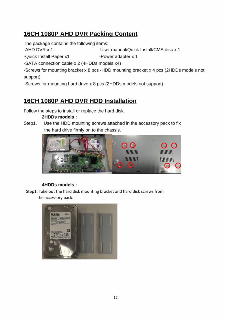
16CH 1080P AHD DVR HDD Installation
Follow the steps to install or replace the hard disk.
2HDDs models :
Step1. Use the HDD mounting screws attached in the accessory pack to fix
the hard drive firmly on to the chassis.
4HDDs models :
Step1. Take out the hard disk mounting bracket and hard disk screws from
the accessory pack.
13
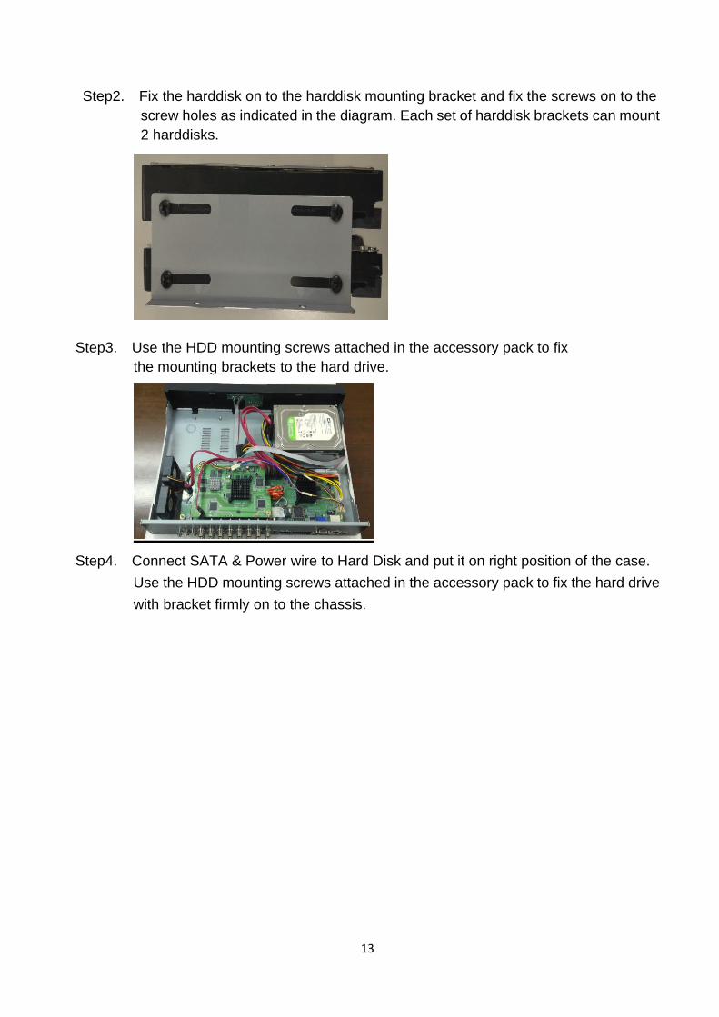
Step2. Fix the harddisk on to the harddisk mounting bracket and fix the screws on to the
screw holes as indicated in the diagram. Each set of harddisk brackets can mount
2 harddisks.
Step3. Use the HDD mounting screws attached in the accessory pack to fix
the mounting brackets to the hard drive.
Step4. Connect SATA & Power wire to Hard Disk and put it on right position of the case.
Use the HDD mounting screws attached in the accessory pack to fix the hard drive
with bracket firmly on to the chassis.
14
2. General Operation
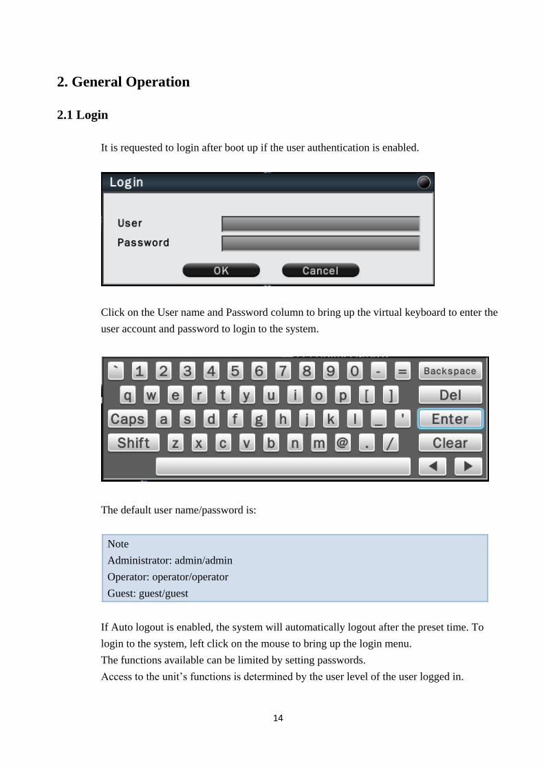
2.1 Login
It is requested to login after boot up if the user authentication is enabled.
Click on the User name and Password column to bring up the virtual keyboard to enter the
user account and password to login to the system.
The default user name/password is:
Note
Administrator: admin/admin
Operator: operator/operator
Guest: guest/guest
If Auto logout is enabled, the system will automatically logout after the preset time. To
login to the system, left click on the mouse to bring up the login menu.
The functions available can be limited by setting passwords.
Access to the unit’s functions is determined by the user level of the user logged in.
15
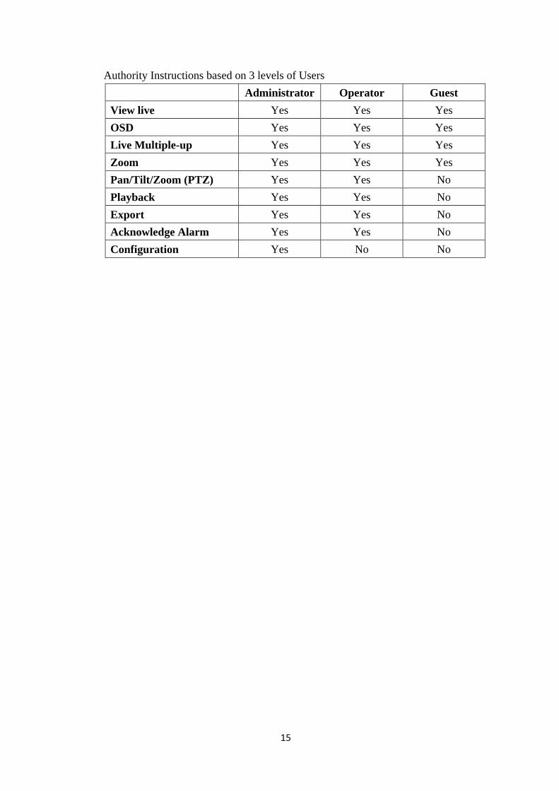
Authority Instructions based on 3 levels of Users
Administrator Operator Guest
View live Yes Yes Yes
OSD Yes Yes Yes
Live Multiple-up Yes Yes Yes
Zoom Yes Yes Yes
Pan/Tilt/Zoom (PTZ) Yes Yes No
Playback Yes Yes No
Export Yes Yes No
Acknowledge Alarm Yes Yes No
Configuration Yes No No
16
2.2 Live Viewing
2.2.1 Basic Operation
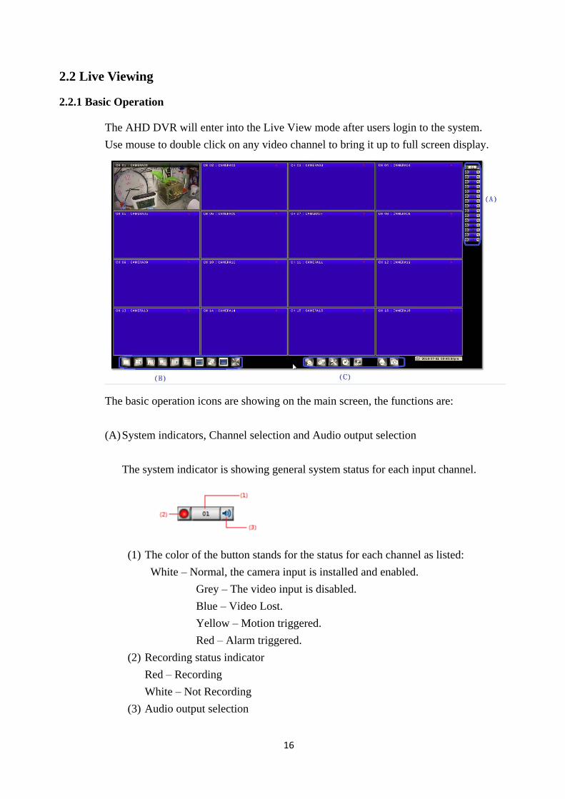
The AHD DVR will enter into the Live View mode after users login to the system.
Use mouse to double click on any video channel to bring it up to full screen display.
The basic operation icons are showing on the main screen, the functions are:
(A) System indicators, Channel selection and Audio output selection
The system indicator is showing general system status for each input channel.
(1) The color of the button stands for the status for each channel as listed:
White – Normal, the camera input is installed and enabled.
Grey – The video input is disabled.
Blue – Video Lost.
Yellow – Motion triggered.
Red – Alarm triggered.
(2) Recording status indicator
Red – Recording
White – Not Recording
(3) Audio output selection
17
Click on the Audio icon on the channel you would like to display, the audio
output will switch to the selected channel.
(4) To switch channel in the display window, move the focus channel to the selected
window, click on the channel button you wish to display, the channel will be
switched.
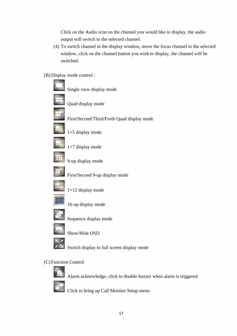
(B) Display mode control :
Single view display mode
Quad display mode
First/Second/Third/Forth Quad display mode
1+5 display mode
1+7 display mode
9-up display mode
First/Second 9-up display mode
1+12 display mode
16-up display mode
Sequence display mode
Show/Hide OSD
Switch display to full screen display mode
(C) Function Control
Alarm acknowledge, click to disable buzzer when alarm is triggered
Click to bring up Call Monitor Setup menu
18
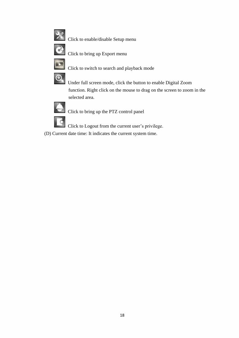
Click to enable/disable Setup menu
Click to bring up Export menu
Click to switch to search and playback mode
Under full screen mode, click the button to enable Digital Zoom
function. Right click on the mouse to drag on the screen to zoom in the
selected area.
Click to bring up the PTZ control panel
Click to Logout from the current user’s privilege.
(D) Current date time: It indicates the current system time.
19
3. Search (Playback) Operation
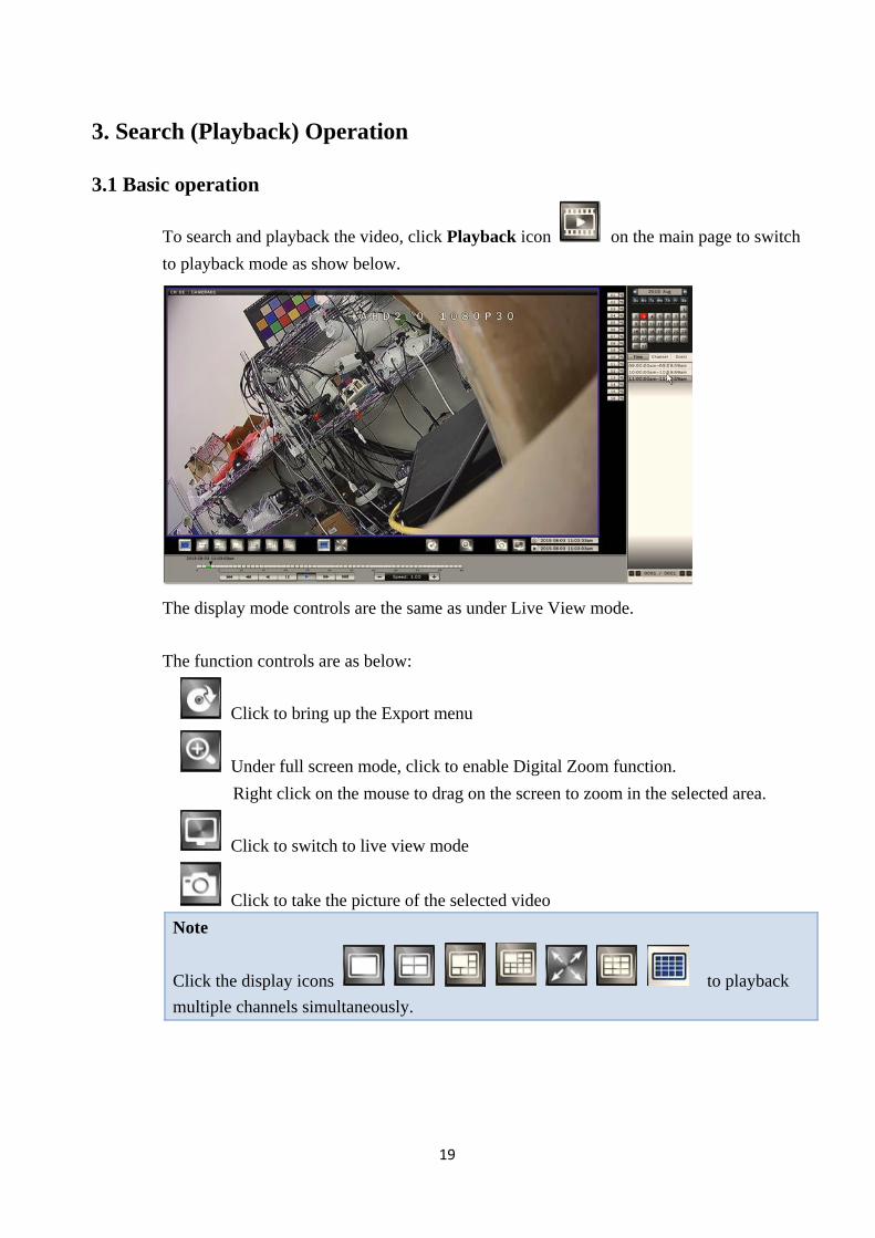
3.1 Basic operation
To search and playback the video, click Playback icon on the main page to switch
to playback mode as show below.
The display mode controls are the same as under Live View mode.
The function controls are as below:
Click to bring up the Export menu
Under full screen mode, click to enable Digital Zoom function.
Right click on the mouse to drag on the screen to zoom in the selected area.
Click to switch to live view mode
Click to take the picture of the selected video
Note
Click the display icons to playback
multiple channels simultaneously.
20
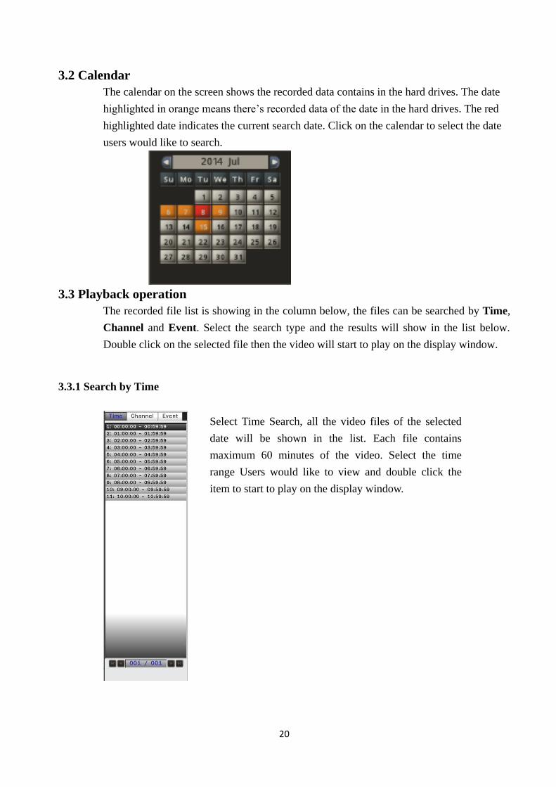
3.2 Calendar
The calendar on the screen shows the recorded data contains in the hard drives. The date
highlighted in orange means there’s recorded data of the date in the hard drives. The red
highlighted date indicates the current search date. Click on the calendar to select the date
users would like to search.
3.3 Playback operation
The recorded file list is showing in the column below, the files can be searched by Time,
Channel and Event. Select the search type and the results will show in the list below.
Double click on the selected file then the video will start to play on the display window.
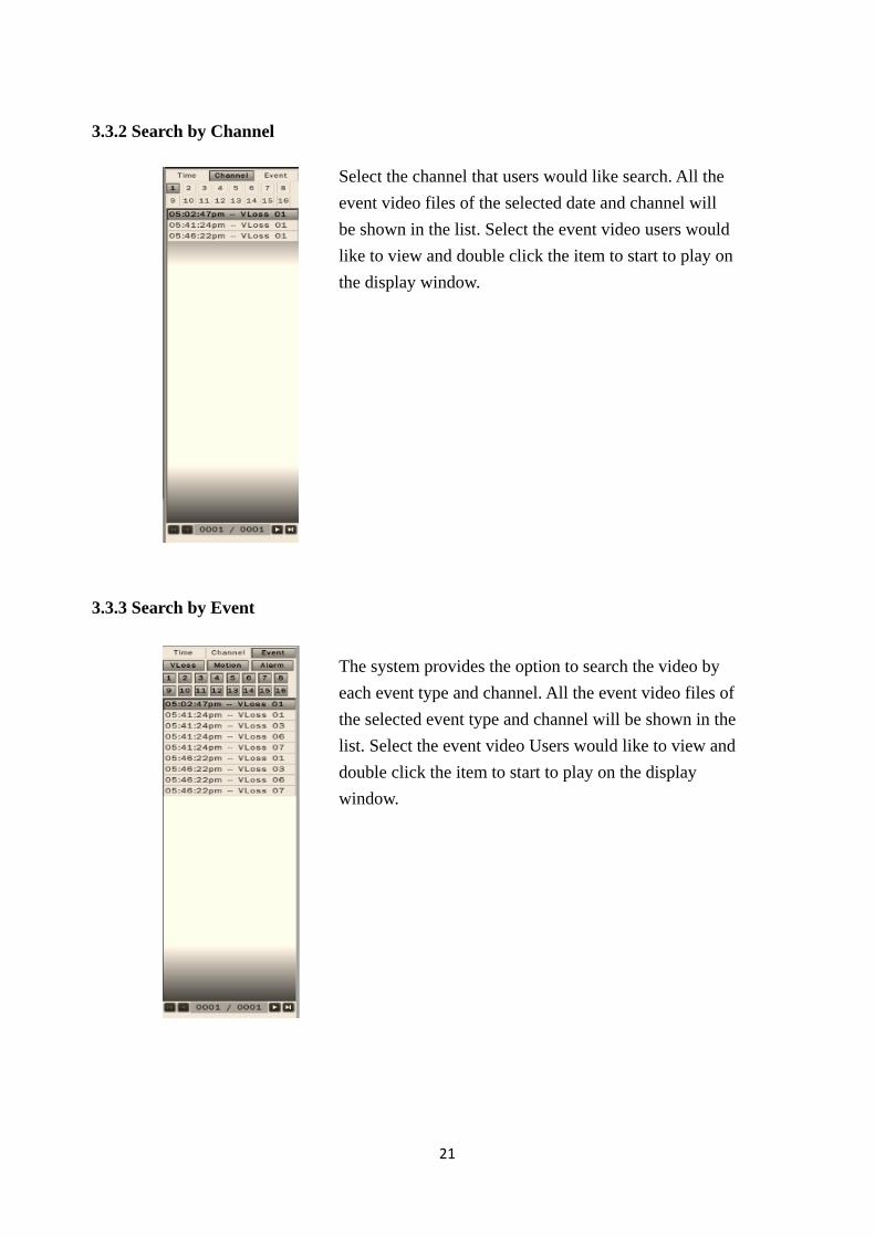
3.3.1 Search by Time
Select Time Search, all the video files of the selected
date will be shown in the list. Each file contains
maximum 60 minutes of the video. Select the time
range Users would like to view and double click the
item to start to play on the display window.
21
3.3.2 Search by Channel
3.3.3 Search by Event
Select the channel that users would like search. All the
event video files of the selected date and channel will
be shown in the list. Select the event video users would
like to view and double click the item to start to play on
the display window.
The system provides the option to search the video by
each event type and channel. All the event video files of
the selected event type and channel will be shown in the
list. Select the event video Users would like to view and
double click the item to start to play on the display
window.
22
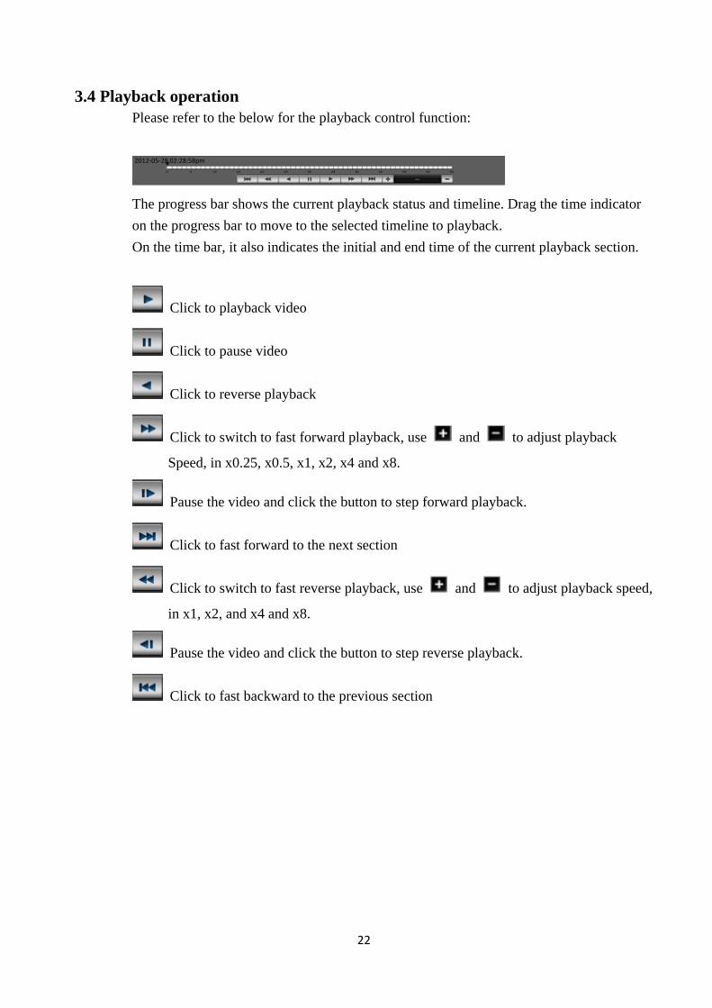
3.4 Playback operation
Please refer to the below for the playback control function:
The progress bar shows the current playback status and timeline. Drag the time indicator
on the progress bar to move to the selected timeline to playback.
On the time bar, it also indicates the initial and end time of the current playback section.
Click to playback video
Click to pause video
Click to reverse playback
Click to switch to fast forward playback, use and to adjust playback
Speed, in x0.25, x0.5, x1, x2, x4 and x8.
Pause the video and click the button to step forward playback.
Click to fast forward to the next section
Click to switch to fast reverse playback, use and to adjust playback speed,
in x1, x2, and x4 and x8.
Pause the video and click the button to step reverse playback.
Click to fast backward to the previous section
2012-05-28 02:28:58pm
23
4. Recording
AHD DVR is set to continually record once the system startup. AHD DVR supports the
following recording mode.
Continuous recording: By default, all channels are enabled with continuous
recording.
Event recording: AHD DVR can be configured to record event only when motion or
video loss or alarm is detected. When motion of Camera is detected, the motion icon
(M) appears in the channel and AHD DVR will start to record. When video loss of
camera occurs, the Video loss icon (V) appears in the channel and AHD DVR will
start to record. When external alarm device is triggered, the alarm icon (A) appears in
the channel and AHD DVR will start to record.
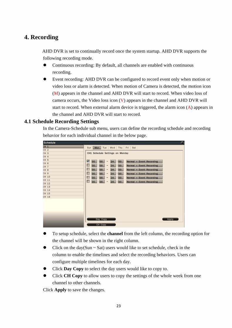
4.1 Schedule Recording Settings
In the Camera-Schedule sub menu, users can define the recording schedule and recording
behavior for each individual channel in the below page.
To setup schedule, select the channel from the left column, the recording option for
the channel will be shown in the right column.
Click on the day(Sun ~ Sat) users would like to set schedule, check in the
column to enable the timelines and select the recording behaviors. Users can
configure multiple timelines for each day.
Click Day Copy to select the day users would like to copy to.
Click CH Copy to allow users to copy the settings of the whole week from one
channel to other channels.
Click Apply to save the changes.
24
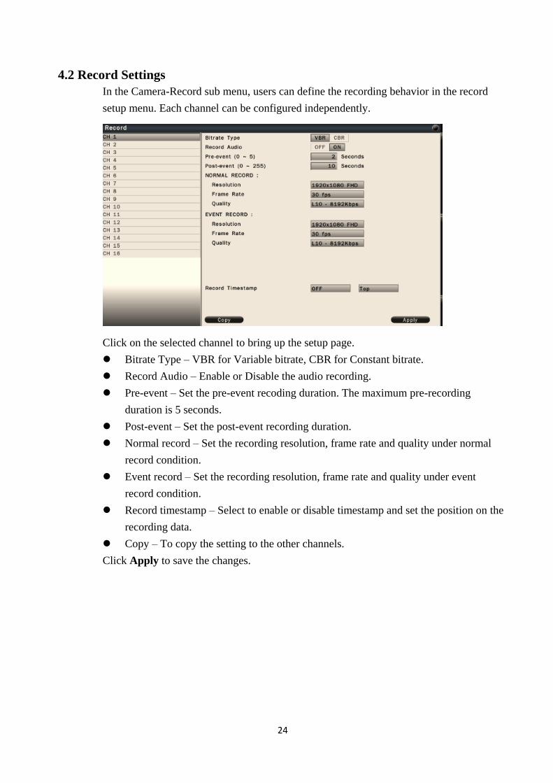
4.2 Record Settings
In the Camera-Record sub menu, users can define the recording behavior in the record
setup menu. Each channel can be configured independently.
Click on the selected channel to bring up the setup page.
Bitrate Type – VBR for Variable bitrate, CBR for Constant bitrate.
Record Audio – Enable or Disable the audio recording.
Pre-event – Set the pre-event recoding duration. The maximum pre-recording
duration is 5 seconds.
Post-event – Set the post-event recording duration.
Normal record – Set the recording resolution, frame rate and quality under normal
record condition.
Event record – Set the recording resolution, frame rate and quality under event
record condition.
Record timestamp – Select to enable or disable timestamp and set the position on the
recording data.
Copy – To copy the setting to the other channels.
Click Apply to save the changes.
25
5. PTZ Control
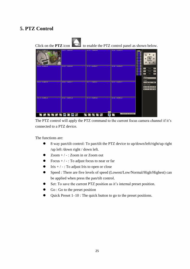
Click on the PTZ icon to enable the PTZ control panel as shown below.
The PTZ control will apply the PTZ command to the current focus camera channel if it’s
connected to a PTZ device.
The functions are:
8 way pan/tilt control: To pan/tilt the PTZ device to up/down/left/right/up right
/up left /down right / down left.
Zoom + / - : Zoom in or Zoom out
Focus + / - : To adjust focus to near or far
Iris + / - : To adjust Iris to open or close
Speed : There are five levels of speed (Lowest/Low/Normal/High/Highest) can
be applied when press the pan/tilt control.
Set: To save the current PTZ position as it’s internal preset position.
Go : Go to the preset position
Quick Preset 1–10 : The quick button to go to the preset positions.
26
6. Export (Backup) Video
To export the video from AHD DVR hard disk to external USB drive device or
self-powered USB external hard drive.
6.1 Export Video
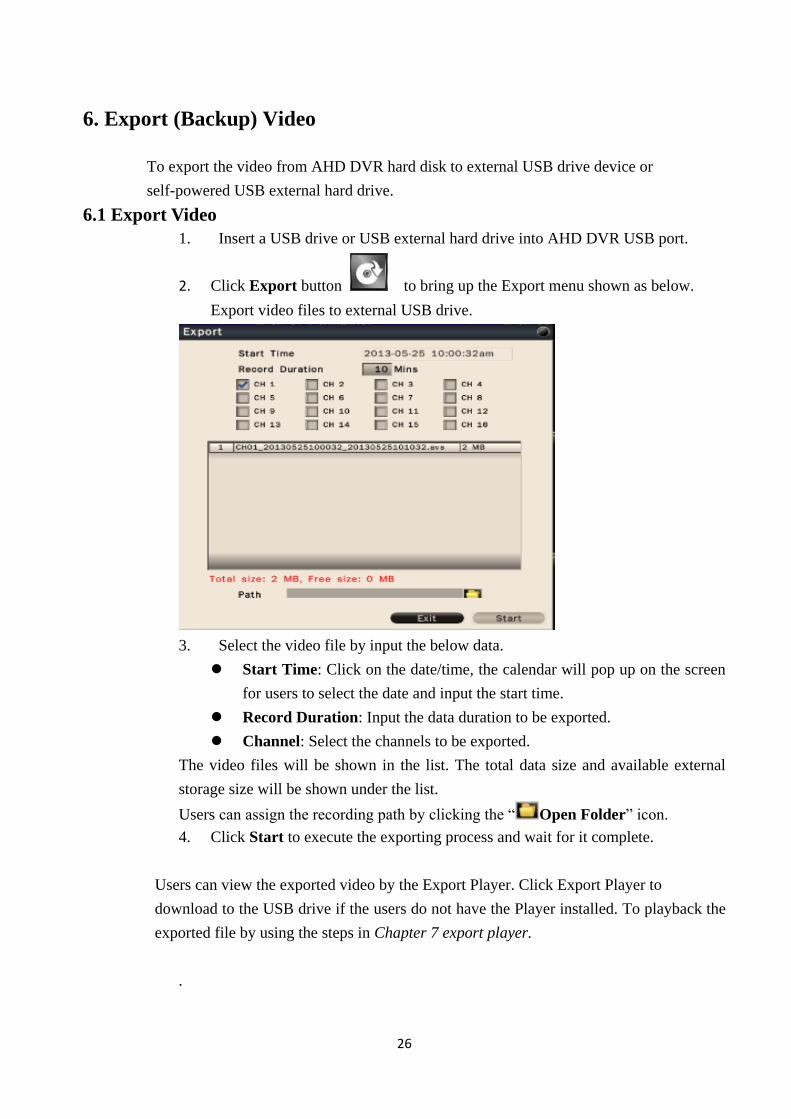
1. Insert a USB drive or USB external hard drive into AHD DVR USB port.
2. Click Export button to bring up the Export menu shown as below.
Export video files to external USB drive.
3. Select the video file by input the below data.
Start Time: Click on the date/time, the calendar will pop up on the screen
for users to select the date and input the start time.
Record Duration: Input the data duration to be exported.
Channel: Select the channels to be exported.
The video files will be shown in the list. The total data size and available external
storage size will be shown under the list.
Users can assign the recording path by clicking the “ Open Folder” icon.
4. Click Start to execute the exporting process and wait for it complete.
Users can view the exported video by the Export Player. Click Export Player to
download to the USB drive if the users do not have the Player installed. To playback the
exported file by using the steps in Chapter 7 export player.
.
27
7. Export Player
The Export Player allows users to view video exported from the AHD DVR or Web
viewer on a PC (System operating platform: Windows XP, Windows Vista, Windows 7 or
Windows 8).
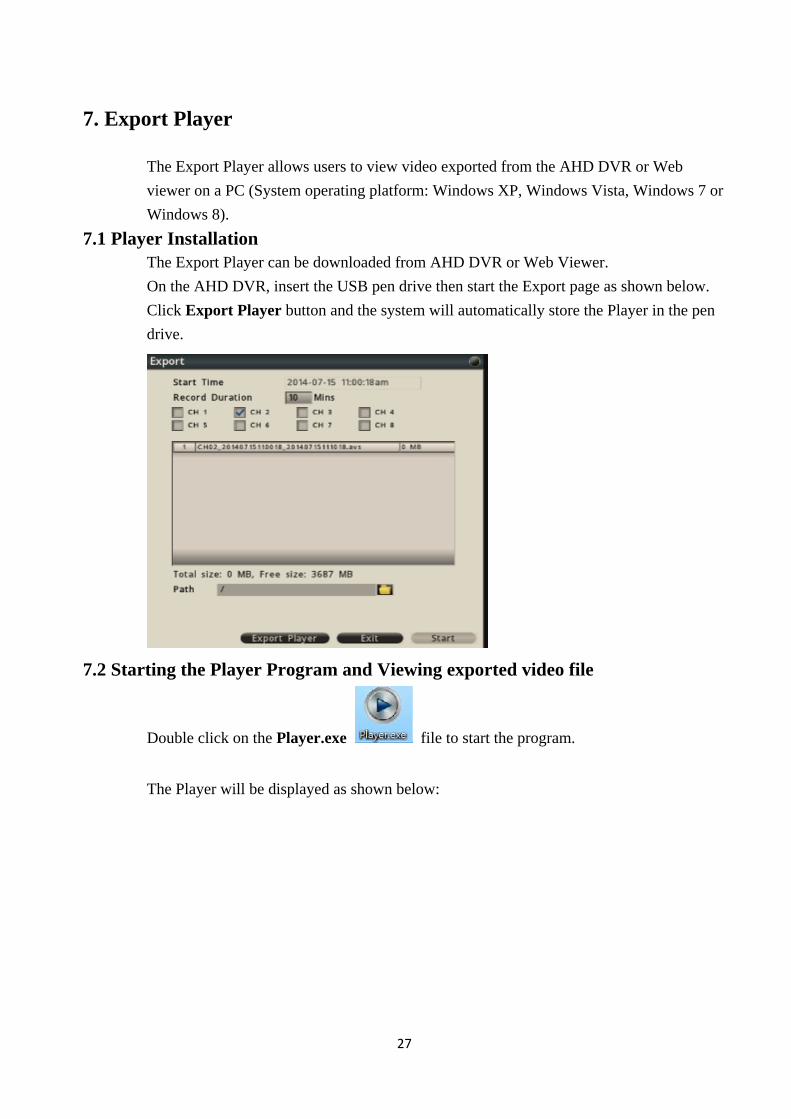
7.1 Player Installation
The Export Player can be downloaded from AHD DVR or Web Viewer.
On the AHD DVR, insert the USB pen drive then start the Export page as shown below.
Click Export Player button and the system will automatically store the Player in the pen
drive.
7.2 Starting the Player Program and Viewing exported video file
Double click on the Player.exe file to start the program.
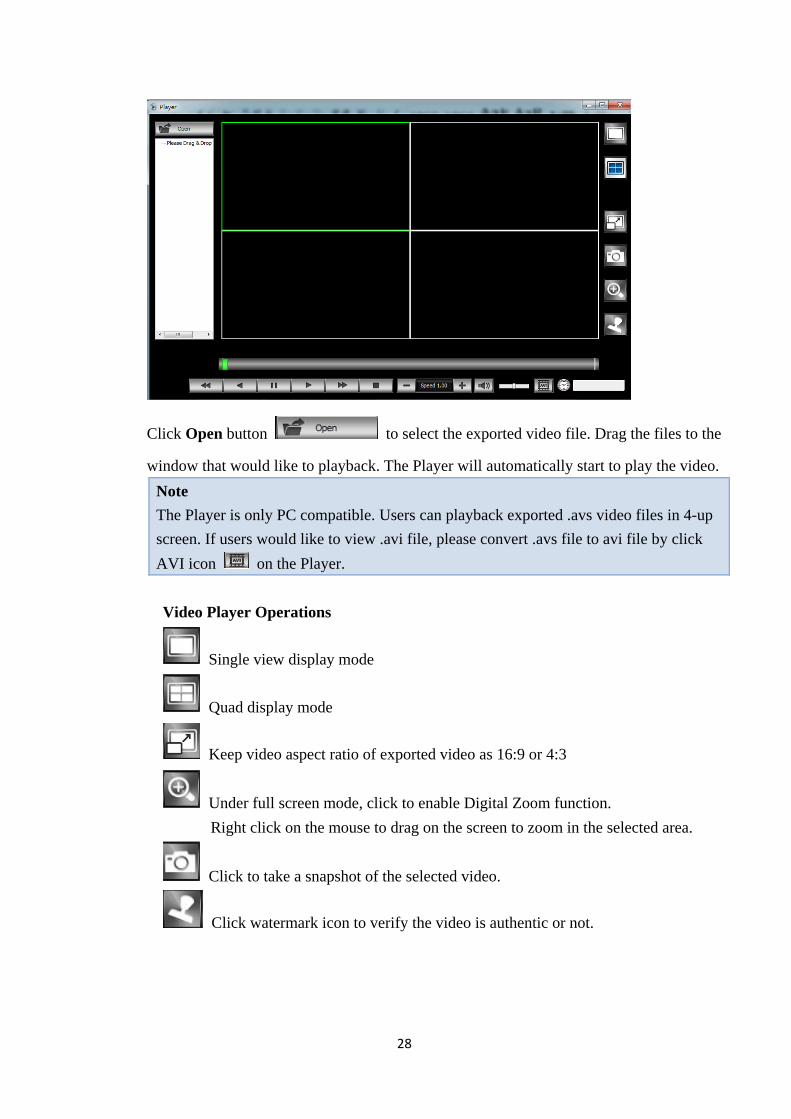
The Player will be displayed as shown below:
28
Click Open button to select the exported video file. Drag the files to the
window that would like to playback. The Player will automatically start to play the video.
Note
The Player is only PC compatible. Users can playback exported .avs video files in 4-up
screen. If users would like to view .avi file, please convert .avs file to avi file by click
AVI icon on the Player.
Video Player Operations
Single view display mode
Quad display mode
Keep video aspect ratio of exported video as 16:9 or 4:3
Under full screen mode, click to enable Digital Zoom function.
Right click on the mouse to drag on the screen to zoom in the selected area.
Click to take a snapshot of the selected video.
Click watermark icon to verify the video is authentic or not.
29
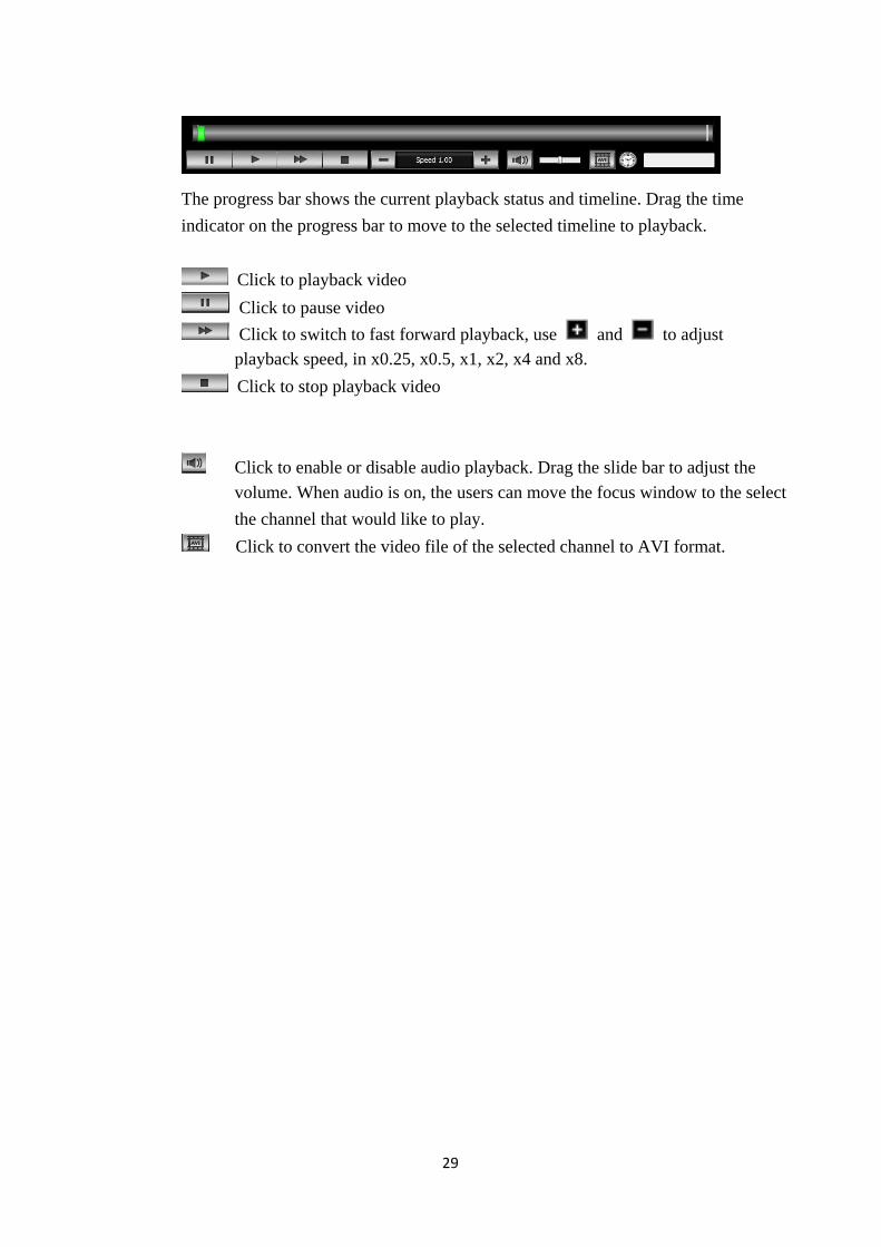
The progress bar shows the current playback status and timeline. Drag the time
indicator on the progress bar to move to the selected timeline to playback.
Click to playback video
Click to pause video
Click to switch to fast forward playback, use and to adjust
playback speed, in x0.25, x0.5, x1, x2, x4 and x8.
Click to stop playback video
Click to enable or disable audio playback. Drag the slide bar to adjust the
volume. When audio is on, the users can move the focus window to the select
the channel that would like to play.
Click to convert the video file of the selected channel to AVI format.
30
8. Main Menu Operations
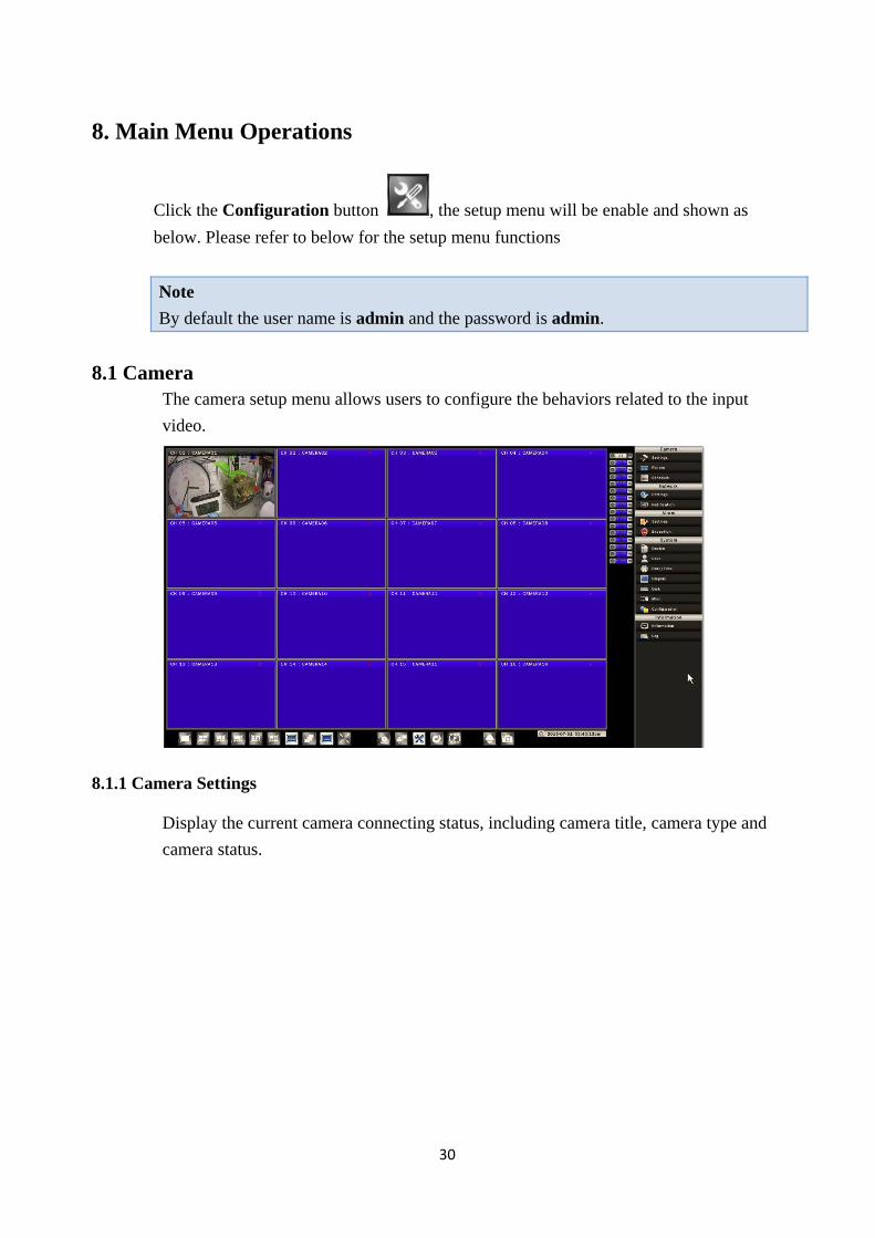
Click the Configuration button , the setup menu will be enable and shown as
below. Please refer to below for the setup menu functions
Note
By default the user name is admin and the password is admin.
8.1 Camera
The camera setup menu allows users to configure the behaviors related to the input
video.
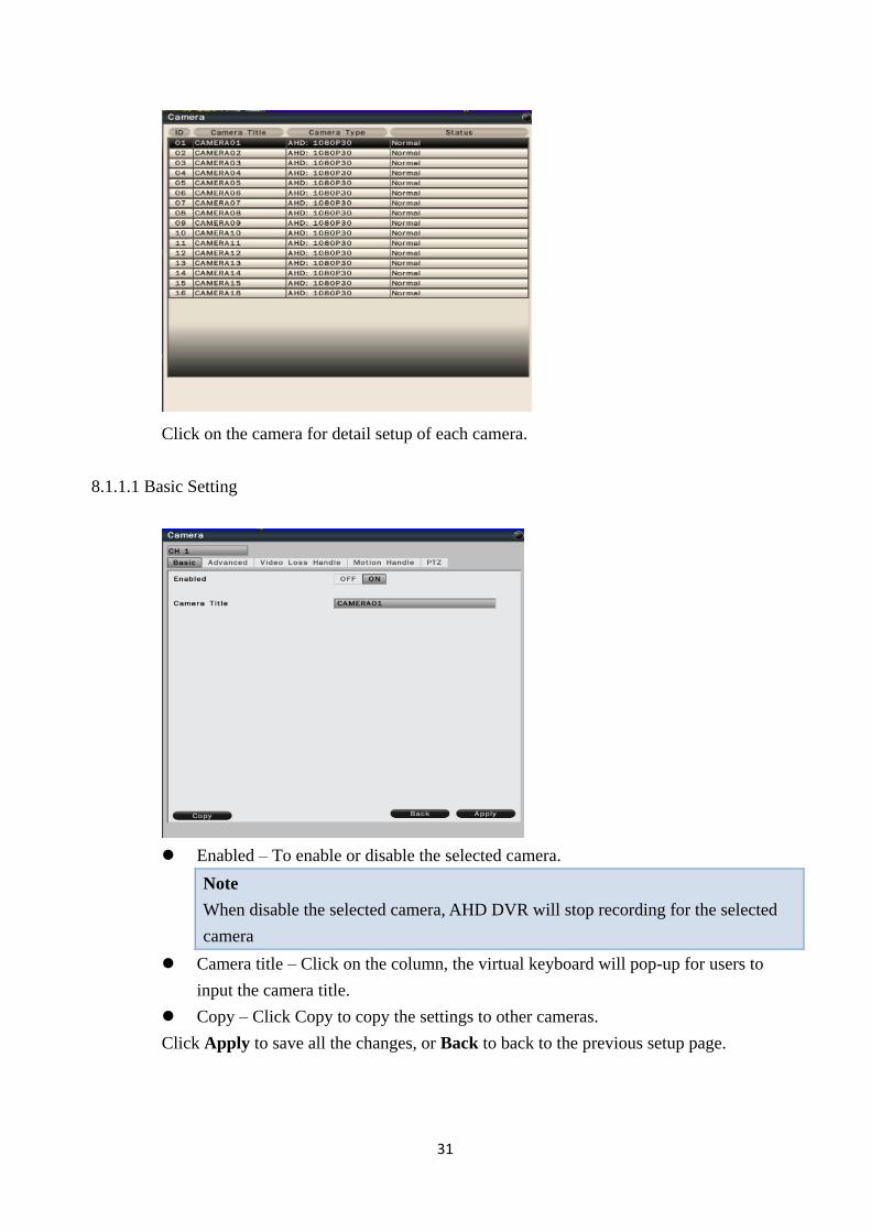
8.1.1 Camera Settings
Display the current camera connecting status, including camera title, camera type and
camera status.
31
Click on the camera for detail setup of each camera.
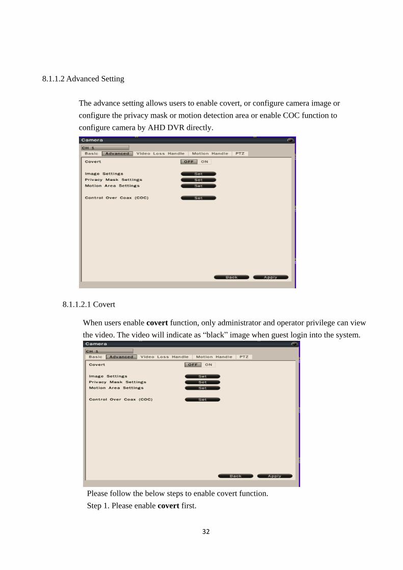
8.1.1.1 Basic Setting
Enabled – To enable or disable the selected camera.
Note
When disable the selected camera, AHD DVR will stop recording for the selected
camera
Camera title – Click on the column, the virtual keyboard will pop-up for users to
input the camera title.
Copy – Click Copy to copy the settings to other cameras.
Click Apply to save all the changes, or Back to back to the previous setup page.
32
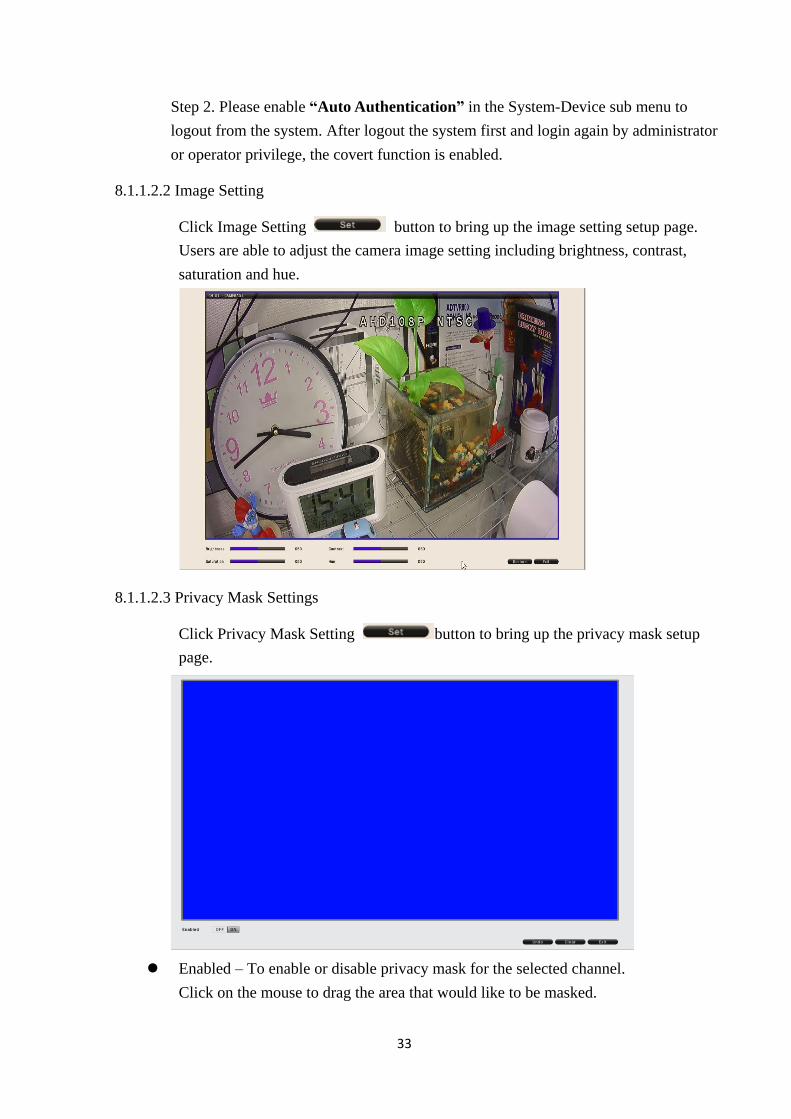
8.1.1.2 Advanced Setting
The advance setting allows users to enable covert, or configure camera image or
configure the privacy mask or motion detection area or enable COC function to
configure camera by AHD DVR directly.
8.1.1.2.1 Covert
When users enable covert function, only administrator and operator privilege can view
the video. The video will indicate as “black” image when guest login into the system.
Please follow the below steps to enable covert function.
Step 1. Please enable covert first.
33
Step 2. Please enable “Auto Authentication” in the System-Device sub menu to
logout from the system. After logout the system first and login again by administrator
or operator privilege, the covert function is enabled.
8.1.1.2.2 Image Setting
Click Image Setting button to bring up the image setting setup page.
Users are able to adjust the camera image setting including brightness, contrast,
saturation and hue.
8.1.1.2.3 Privacy Mask Settings
Click Privacy Mask Setting button to bring up the privacy mask setup
page.
Enabled – To enable or disable privacy mask for the selected channel.
Click on the mouse to drag the area that would like to be masked.
34
Click Undo to undo the step, Clear to clear all the set area, Exit to leave the setting
page.
8.1.1.2.4 Motion Area Settings
Click Motion Area Setting button to bring up the motion area setting
page as below.
Enables – Select On/Off to enable or disable the option.
Sensitivity – Select the sensitivity, from lowest to highest.
Target Threshold – The target quantity to trigger the motion.
Click Apply to apply the setting, Undo to undo the step, Clear to clear all settings,
Preview to view the current settings, Exit to leave the setup page.
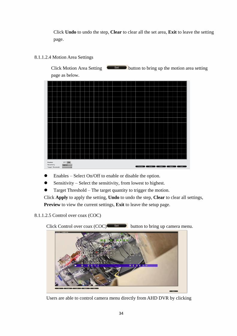
8.1.1.2.5 Control over coax (COC)
Click Control over coax (COC) button to bring up camera menu.
Users are able to control camera menu directly from AHD DVR by clicking
35
buttons.
Note
AHD camera must provide COC function in order to enable it in AHD DVR.
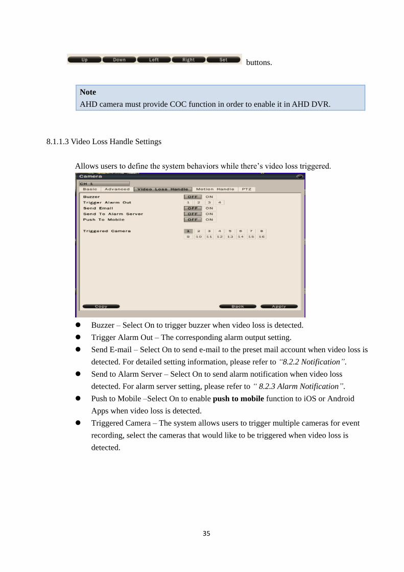
8.1.1.3 Video Loss Handle Settings
Allows users to define the system behaviors while there’s video loss triggered.
Buzzer – Select On to trigger buzzer when video loss is detected.
Trigger Alarm Out – The corresponding alarm output setting.
Send E-mail – Select On to send e-mail to the preset mail account when video loss is
detected. For detailed setting information, please refer to “8.2.2 Notification”.
Send to Alarm Server – Select On to send alarm notification when video loss
detected. For alarm server setting, please refer to “ 8.2.3 Alarm Notification”.
Push to Mobile –Select On to enable push to mobile function to iOS or Android
Apps when video loss is detected.
Triggered Camera – The system allows users to trigger multiple cameras for event
recording, select the cameras that would like to be triggered when video loss is
detected.
36
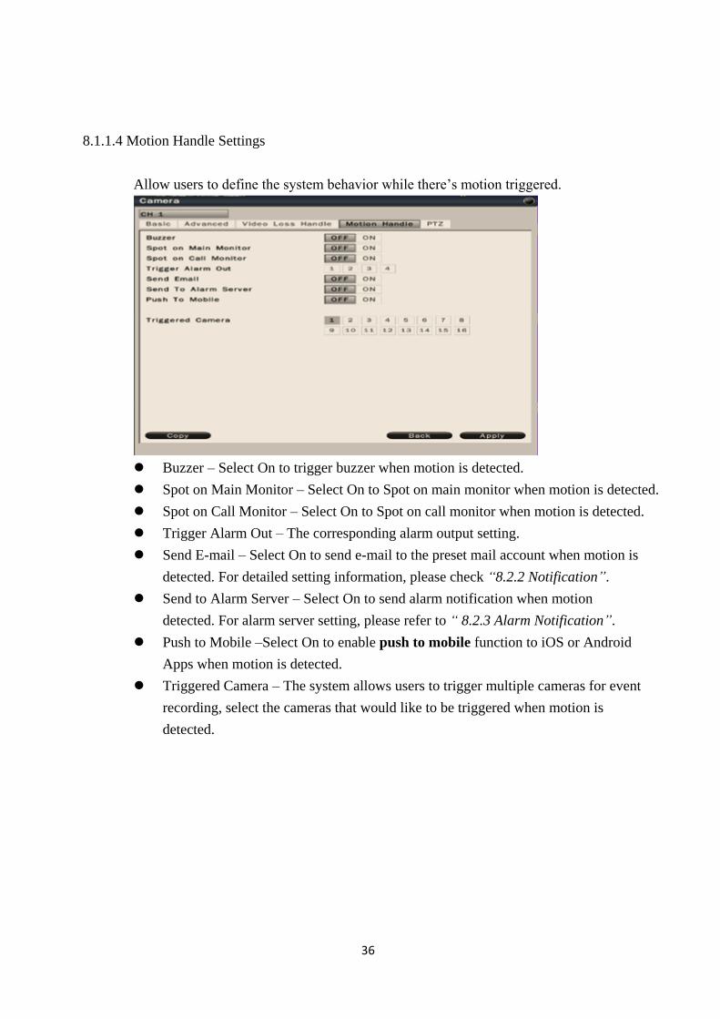
8.1.1.4 Motion Handle Settings
Allow users to define the system behavior while there’s motion triggered.
Buzzer – Select On to trigger buzzer when motion is detected.
Spot on Main Monitor – Select On to Spot on main monitor when motion is detected.
Spot on Call Monitor – Select On to Spot on call monitor when motion is detected.
Trigger Alarm Out – The corresponding alarm output setting.
Send E-mail – Select On to send e-mail to the preset mail account when motion is
detected. For detailed setting information, please check “8.2.2 Notification”.
Send to Alarm Server – Select On to send alarm notification when motion
detected. For alarm server setting, please refer to “ 8.2.3 Alarm Notification”.
Push to Mobile –Select On to enable push to mobile function to iOS or Android
Apps when motion is detected.
Triggered Camera – The system allows users to trigger multiple cameras for event
recording, select the cameras that would like to be triggered when motion is
detected.
37
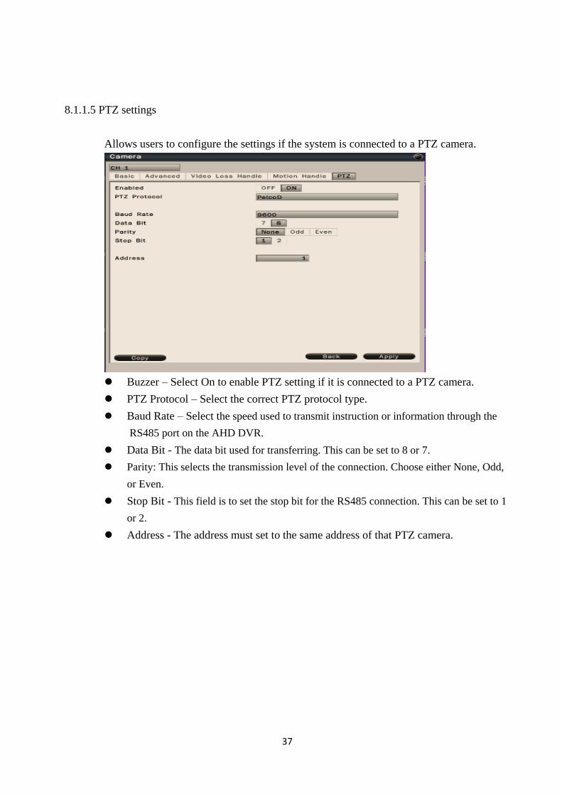
8.1.1.5 PTZ settings
Allows users to configure the settings if the system is connected to a PTZ camera.
Buzzer – Select On to enable PTZ setting if it is connected to a PTZ camera.
PTZ Protocol – Select the correct PTZ protocol type.
Baud Rate – Select the speed used to transmit instruction or information through the
RS485 port on the AHD DVR.
Data Bit - The data bit used for transferring. This can be set to 8 or 7.
Parity: This selects the transmission level of the connection. Choose either None, Odd,
or Even.
Stop Bit - This field is to set the stop bit for the RS485 connection. This can be set to 1
or 2.
Address - The address must set to the same address of that PTZ camera.
38
8.2 Network
8.2.1 Network Settings
The Network function must be enabled and configured properly in order to access the
AHD DVR over the network.
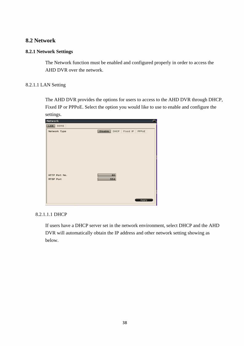
8.2.1.1 LAN Setting
The AHD DVR provides the options for users to access to the AHD DVR through DHCP,
Fixed IP or PPPoE. Select the option you would like to use to enable and configure the
settings.
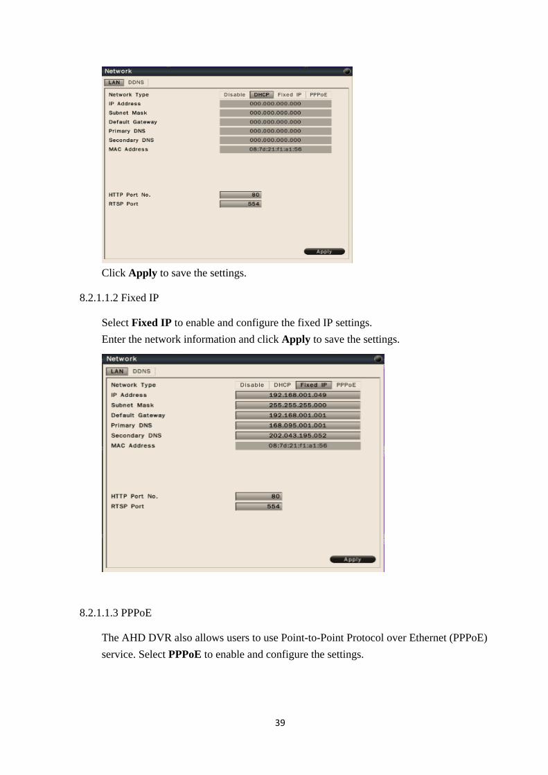
8.2.1.1.1 DHCP
If users have a DHCP server set in the network environment, select DHCP and the AHD
DVR will automatically obtain the IP address and other network setting showing as
below.
39
Click Apply to save the settings.
8.2.1.1.2 Fixed IP
Select Fixed IP to enable and configure the fixed IP settings.
Enter the network information and click Apply to save the settings.
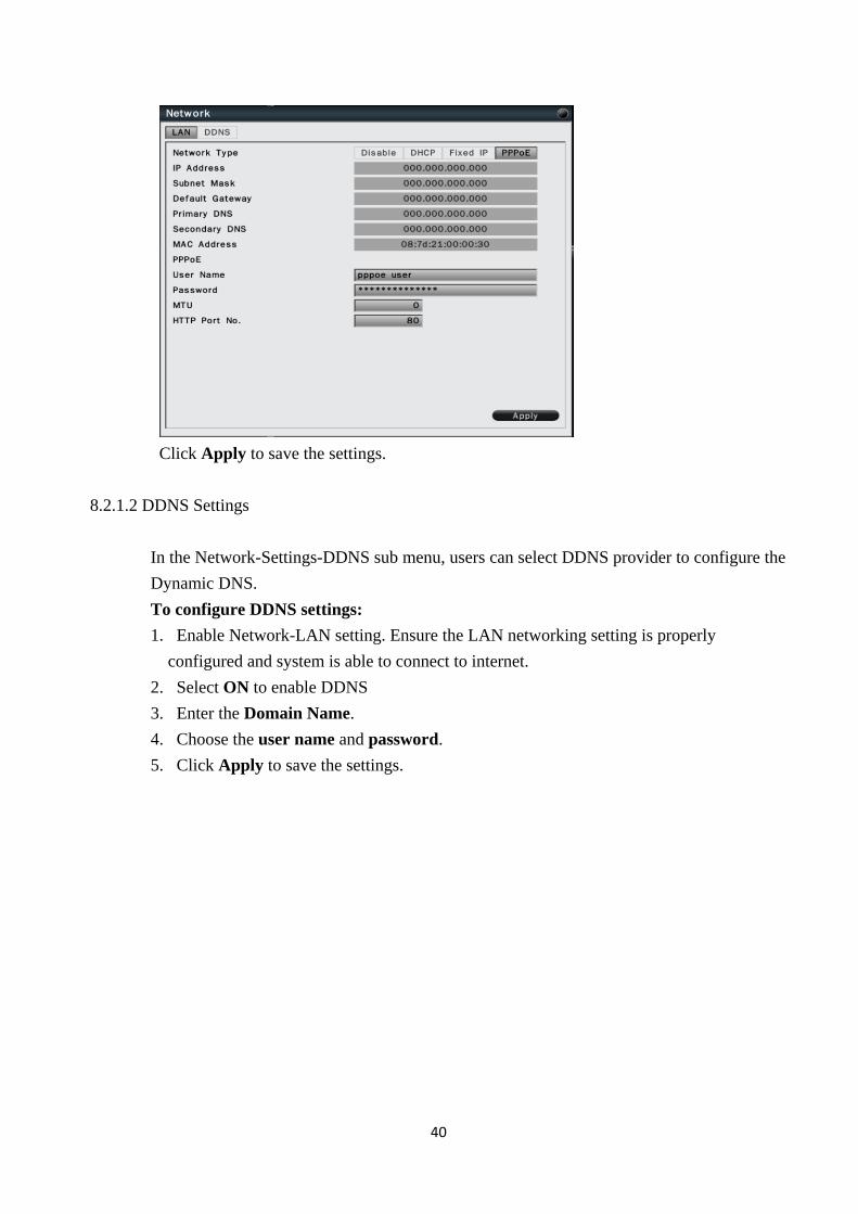
8.2.1.1.3 PPPoE
The AHD DVR also allows users to use Point-to-Point Protocol over Ethernet (PPPoE)
service. Select PPPoE to enable and configure the settings.
40
Click Apply to save the settings.
8.2.1.2 DDNS Settings
In the Network-Settings-DDNS sub menu, users can select DDNS provider to configure the
Dynamic DNS.
To configure DDNS settings:
1. Enable Network-LAN setting. Ensure the LAN networking setting is properly
configured and system is able to connect to internet.
2. Select ON to enable DDNS
3. Enter the Domain Name.
4. Choose the user name and password.
5. Click Apply to save the settings.
41
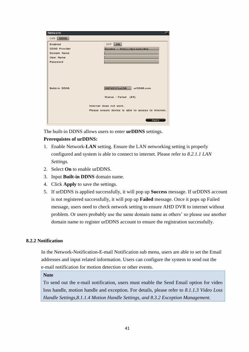
The built-in DDNS allows users to enter urDDNS settings.
Prerequistes of urDDNS:
1. Enable Network-LAN setting. Ensure the LAN networking setting is properly
configured and system is able to connect to internet. Please refer to 8.2.1.1 LAN
Settings.
2. Select On to enable urDDNS.
3. Input Built-in DDNS domain name.
4. Click Apply to save the settings.
5. If urDDNS is applied successfully, it will pop up Success message. If urDDNS account
is not registered successfully, it will pop up Failed message. Once it pops up Failed
message, users need to check network setting to ensure AHD DVR to internet without
problem. Or users probably use the same domain name as others’ so please use another
domain name to register urDDNS account to ensure the registration successfully.
8.2.2 Notification
In the Network-Notification-E-mail Notification sub menu, users are able to set the Email
addresses and input related information. Users can configure the system to send out the
e-mail notification for motion detection or other events.
Note
To send out the e-mail notification, users must enable the Send Email option for video
loss handle, motion handle and exception. For details, please refer to 8.1.1.3 Video Loss
Handle Settings,8.1.1.4 Motion Handle Settings, and 8.3.2 Exception Management.
42
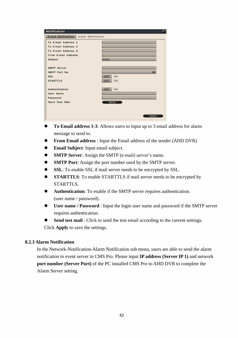
To Email address 1-3: Allows users to input up to 3 email address for alarm
message to send to.
From Email address : Input the Email address of the sender (AHD DVR)
Email Subject: Input email subject.
SMTP Server: Assign the SMTP (e-mail) server’s name.
SMTP Port: Assign the port number used by the SMTP server.
SSL: To enable SSL if mail server needs to be encrypted by SSL.
STARTTLS: To enable STARTTLS if mail server needs to be encrypted by
STARTTLS.
Authentication: To enable if the SMTP server requires authentication.
(user name / password).
User name / Password : Input the login user name and password if the SMTP server
requires authentication.
Send test mail : Click to send the test email according to the current settings.
Click Apply to save the settings.
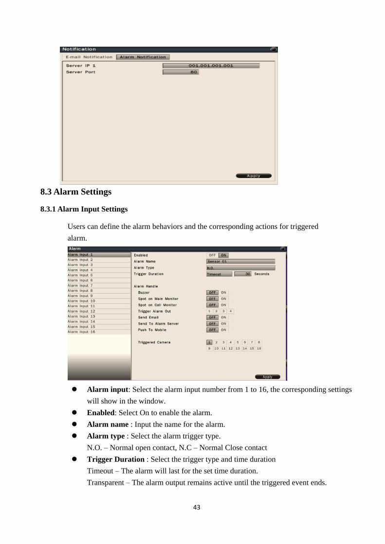
8.2.3 Alarm Notification
In the Network-Notification-Alarm Notification sub menu, users are able to send the alarm
notification to event server in CMS Pro. Please input IP address (Server IP 1) and network
port number (Server Port) of the PC installed CMS Pro to AHD DVR to complete the
Alarm Server setting.
43
8.3 Alarm Settings
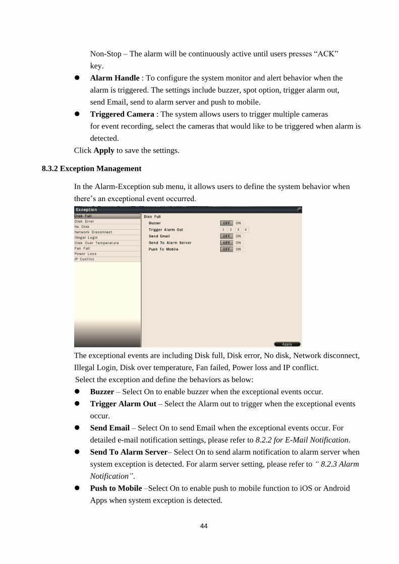
8.3.1 Alarm Input Settings
Users can define the alarm behaviors and the corresponding actions for triggered
alarm.
Alarm input: Select the alarm input number from 1 to 16, the corresponding settings
will show in the window.
Enabled: Select On to enable the alarm.
Alarm name : Input the name for the alarm.
Alarm type : Select the alarm trigger type.
N.O. – Normal open contact, N.C – Normal Close contact
Trigger Duration : Select the trigger type and time duration
Timeout – The alarm will last for the set time duration.
Transparent – The alarm output remains active until the triggered event ends.
44
Non-Stop – The alarm will be continuously active until users presses “ACK”
key.
Alarm Handle : To configure the system monitor and alert behavior when the
alarm is triggered. The settings include buzzer, spot option, trigger alarm out,
send Email, send to alarm server and push to mobile.
Triggered Camera : The system allows users to trigger multiple cameras
for event recording, select the cameras that would like to be triggered when alarm is
detected.
Click Apply to save the settings.
8.3.2 Exception Management
In the Alarm-Exception sub menu, it allows users to define the system behavior when
there’s an exceptional event occurred.
The exceptional events are including Disk full, Disk error, No disk, Network disconnect,
Illegal Login, Disk over temperature, Fan failed, Power loss and IP conflict.
Select the exception and define the behaviors as below:
Buzzer – Select On to enable buzzer when the exceptional events occur.
Trigger Alarm Out – Select the Alarm out to trigger when the exceptional events
occur.
Send Email – Select On to send Email when the exceptional events occur. For
detailed e-mail notification settings, please refer to 8.2.2 for E-Mail Notification.
Send To Alarm Server– Select On to send alarm notification to alarm server when
system exception is detected. For alarm server setting, please refer to “ 8.2.3 Alarm
Notification”.
Push to Mobile –Select On to enable push to mobile function to iOS or Android
Apps when system exception is detected.

45
8.4 System Settings
8.4.1 Device Setting
In the System-Device sub menu, users can configure the device related settings.
Device Name: Input the name for the AHD DVR.
Device No. : Input the number for the AHD DVR.
Language: Select from the list for the language to be use on the AHD DVR.
Push to Mobile Test : After LAN is enabled and finish the related network setting,
please click Send button to test push to mobile function. Users will get the test
message in VS Viewer Pro Apps.
Enable Authentication: Select On to active the user login. If users select Off, no
users name or password is required to access the system, and all users operate
with administrator’s right.
Click Apply to save the settings.
46
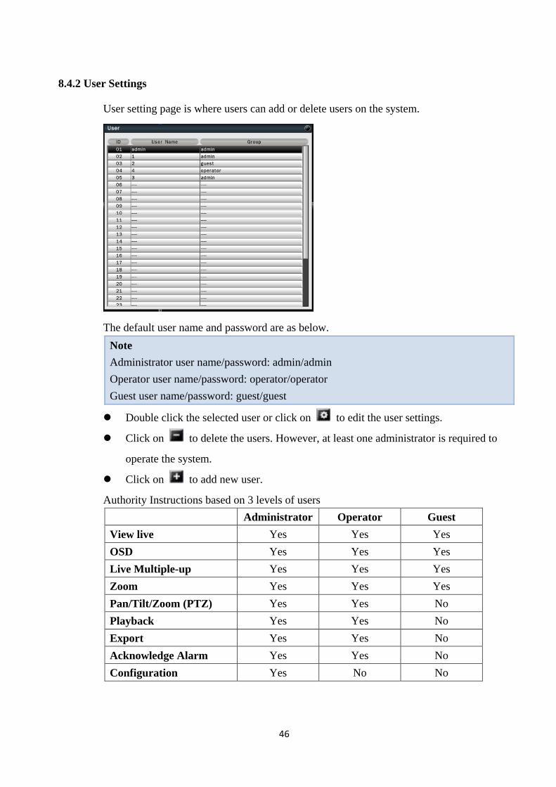
8.4.2 User Settings
User setting page is where users can add or delete users on the system.
The default user name and password are as below.
Note
Administrator user name/password: admin/admin
Operator user name/password: operator/operator
Guest user name/password: guest/guest
Double click the selected user or click on to edit the user settings.
Click on to delete the users. However, at least one administrator is required to
operate the system.
Click on to add new user.
Authority Instructions based on 3 levels of users
Administrator Operator Guest
View live Yes Yes Yes
OSD Yes Yes Yes
Live Multiple-up Yes Yes Yes
Zoom Yes Yes Yes
Pan/Tilt/Zoom (PTZ) Yes Yes No
Playback Yes Yes No
Export Yes Yes No
Acknowledge Alarm Yes Yes No
Configuration Yes No No
47
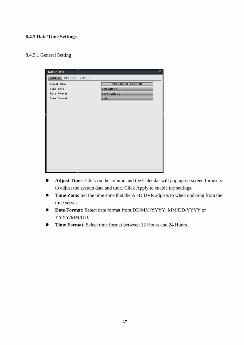
8.4.3 Date/Time Settings
8.4.3.1 General Setting
Adjust Time : Click on the column and the Calendar will pop up on screen for users
to adjust the system date and time. Click Apply to enable the settings.
Time Zone: Set the time zone that the AHD DVR adjusts to when updating from the
time server.
Date Format: Select date format from DD/MM/YYYY, MM/DD/YYYY or
YYYY/MM/DD.
Time Format: Select time format between 12 Hours and 24 Hours.
48
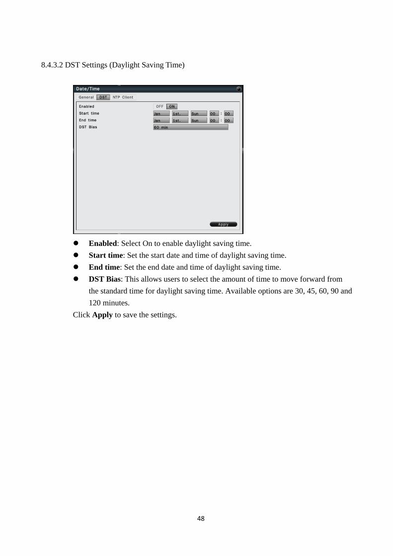
8.4.3.2 DST Settings (Daylight Saving Time)
Enabled: Select On to enable daylight saving time.
Start time: Set the start date and time of daylight saving time.
End time: Set the end date and time of daylight saving time.
DST Bias: This allows users to select the amount of time to move forward from
the standard time for daylight saving time. Available options are 30, 45, 60, 90 and
120 minutes.
Click Apply to save the settings.
49
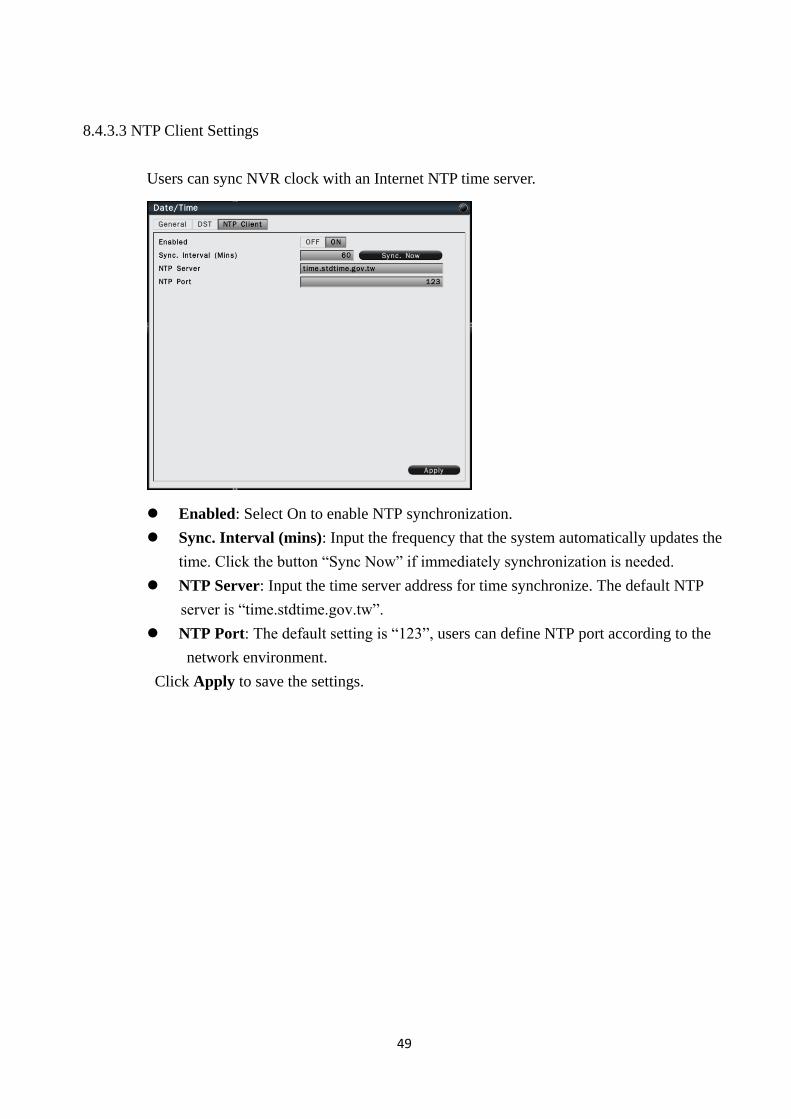
8.4.3.3 NTP Client Settings
Users can sync NVR clock with an Internet NTP time server.
Enabled: Select On to enable NTP synchronization.
Sync. Interval (mins): Input the frequency that the system automatically updates the
time. Click the button “Sync Now” if immediately synchronization is needed.
NTP Server: Input the time server address for time synchronize. The default NTP
server is “time.stdtime.gov.tw”.
NTP Port: The default setting is “123”, users can define NTP port according to the
network environment.
Click Apply to save the settings.
50
8.4.4 Display
The Display setting allows users to define the monitor output behavior.
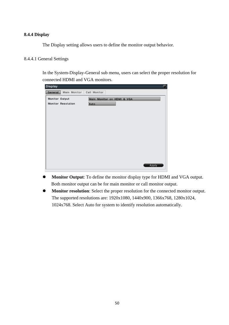
8.4.4.1 General Settings
In the System-Display-General sub menu, users can select the proper resolution for
connected HDMI and VGA monitors.
Monitor Output: To define the monitor display type for HDMI and VGA output.
Both monitor output can be for main monitor or call monitor output.
Monitor resolution: Select the proper resolution for the connected monitor output.
The supported resolutions are: 1920x1080, 1440x900, 1366x768, 1280x1024,
1024x768. Select Auto for system to identify resolution automatically.
51
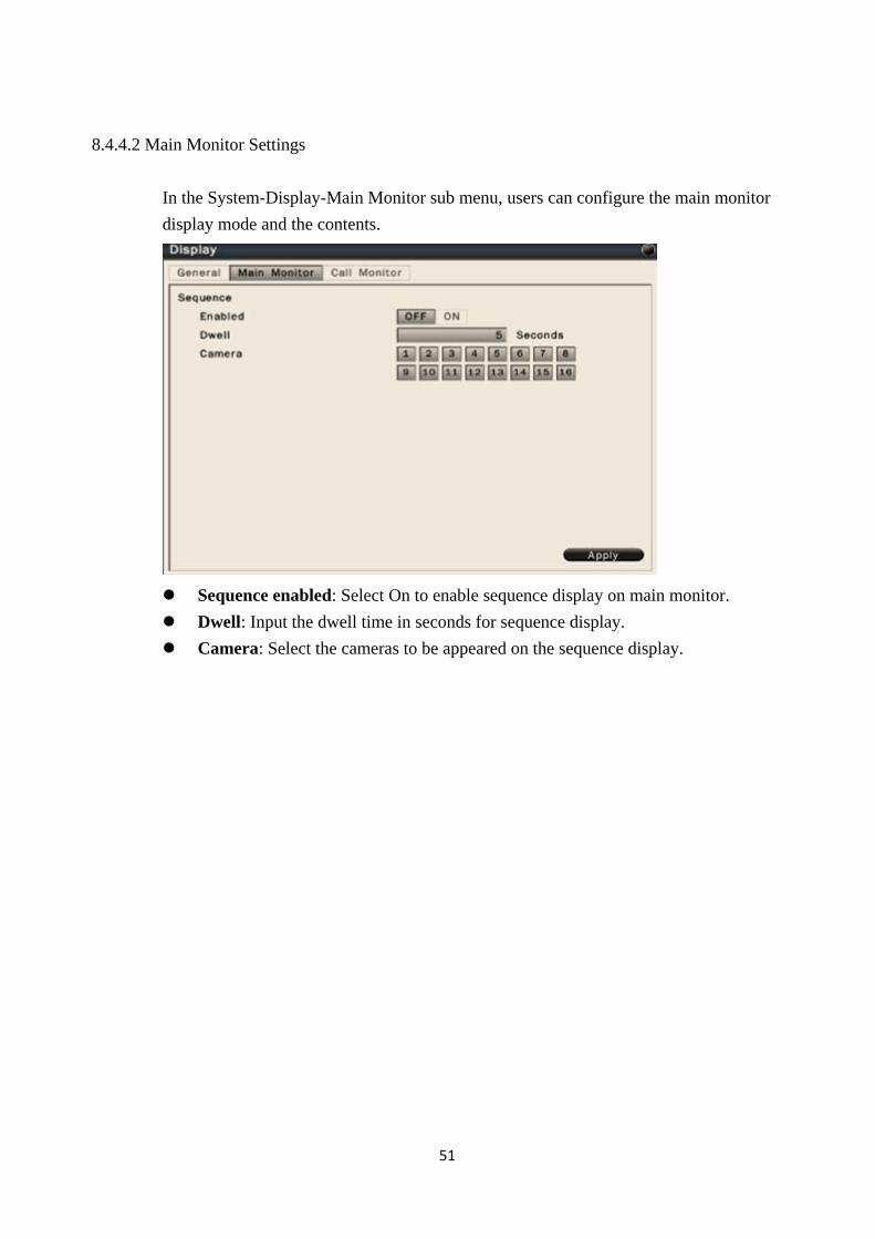
8.4.4.2 Main Monitor Settings
In the System-Display-Main Monitor sub menu, users can configure the main monitor
display mode and the contents.
Sequence enabled: Select On to enable sequence display on main monitor.
Dwell: Input the dwell time in seconds for sequence display.
Camera: Select the cameras to be appeared on the sequence display.
52
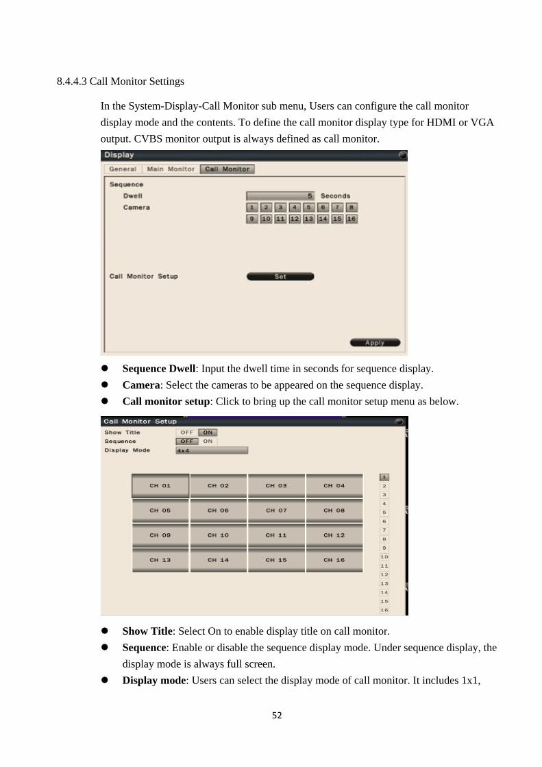
8.4.4.3 Call Monitor Settings
In the System-Display-Call Monitor sub menu, Users can configure the call monitor
display mode and the contents. To define the call monitor display type for HDMI or VGA
output. CVBS monitor output is always defined as call monitor.
Sequence Dwell: Input the dwell time in seconds for sequence display.
Camera: Select the cameras to be appeared on the sequence display.
Call monitor setup: Click to bring up the call monitor setup menu as below.
Show Title: Select On to enable display title on call monitor.
Sequence: Enable or disable the sequence display mode. Under sequence display, the
display mode is always full screen.
Display mode: Users can select the display mode of call monitor. It includes 1x1,
53
2x2, 1+5, 1+7, 3x3, 1+12, 4x4 screen.
Also Users can assign the display video in each cameo by clicking the channel icons
on the right side.
8.4.5 HDD
In the System-Disk sub menu, Users can review and manage the hard disk settings of the
NVR. It allows Users to configure overwrite, auto delete and format HDD.
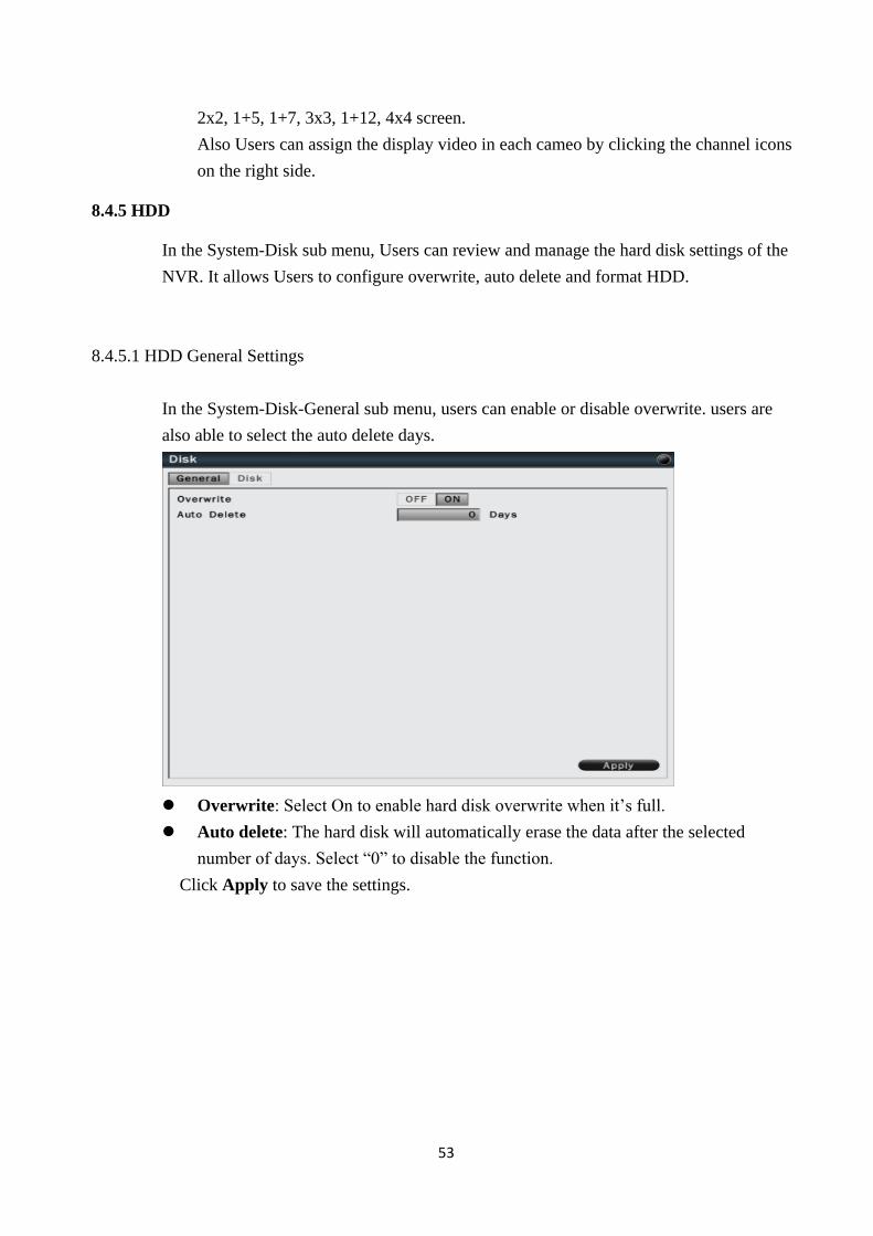
8.4.5.1 HDD General Settings
In the System-Disk-General sub menu, users can enable or disable overwrite. users are
also able to select the auto delete days.
Overwrite: Select On to enable hard disk overwrite when it’s full.
Auto delete: The hard disk will automatically erase the data after the selected
number of days. Select “0” to disable the function.
Click Apply to save the settings.
54
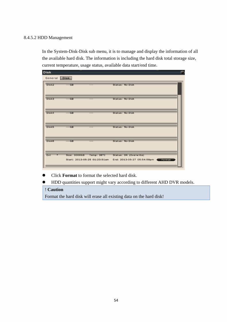
8.4.5.2 HDD Management
In the System-Disk-Disk sub menu, it is to manage and display the information of all
the available hard disk. The information is including the hard disk total storage size,
current temperature, usage status, available data start/end time.
Click Format to format the selected hard disk.
HDD quantities support might vary according to different AHD DVR models.
! Caution
Format the hard disk will erase all existing data on the hard disk!
55
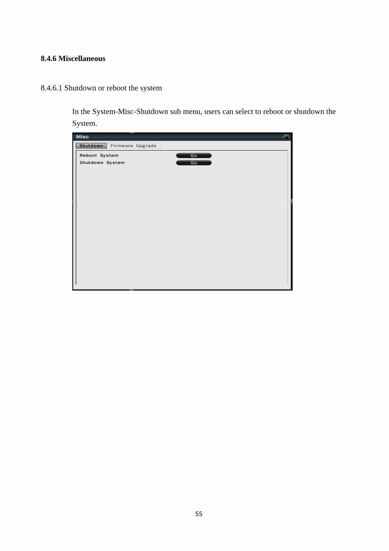
8.4.6 Miscellaneous
8.4.6.1 Shutdown or reboot the system
In the System-Misc-Shutdown sub menu, users can select to reboot or shutdown the
System.
56
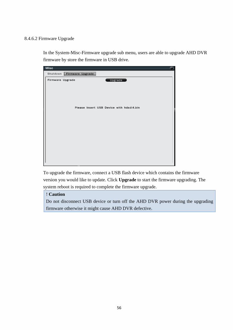
8.4.6.2 Firmware Upgrade
In the System-Misc-Firmware upgrade sub menu, users are able to upgrade AHD DVR
firmware by store the firmware in USB drive.
To upgrade the firmware, connect a USB flash device which contains the firmware
version you would like to update. Click Upgrade to start the firmware upgrading. The
system reboot is required to complete the firmware upgrade.
! Caution
Do not disconnect USB device or turn off the AHD DVR power during the upgrading
firmware otherwise it might cause AHD DVR defective.
57
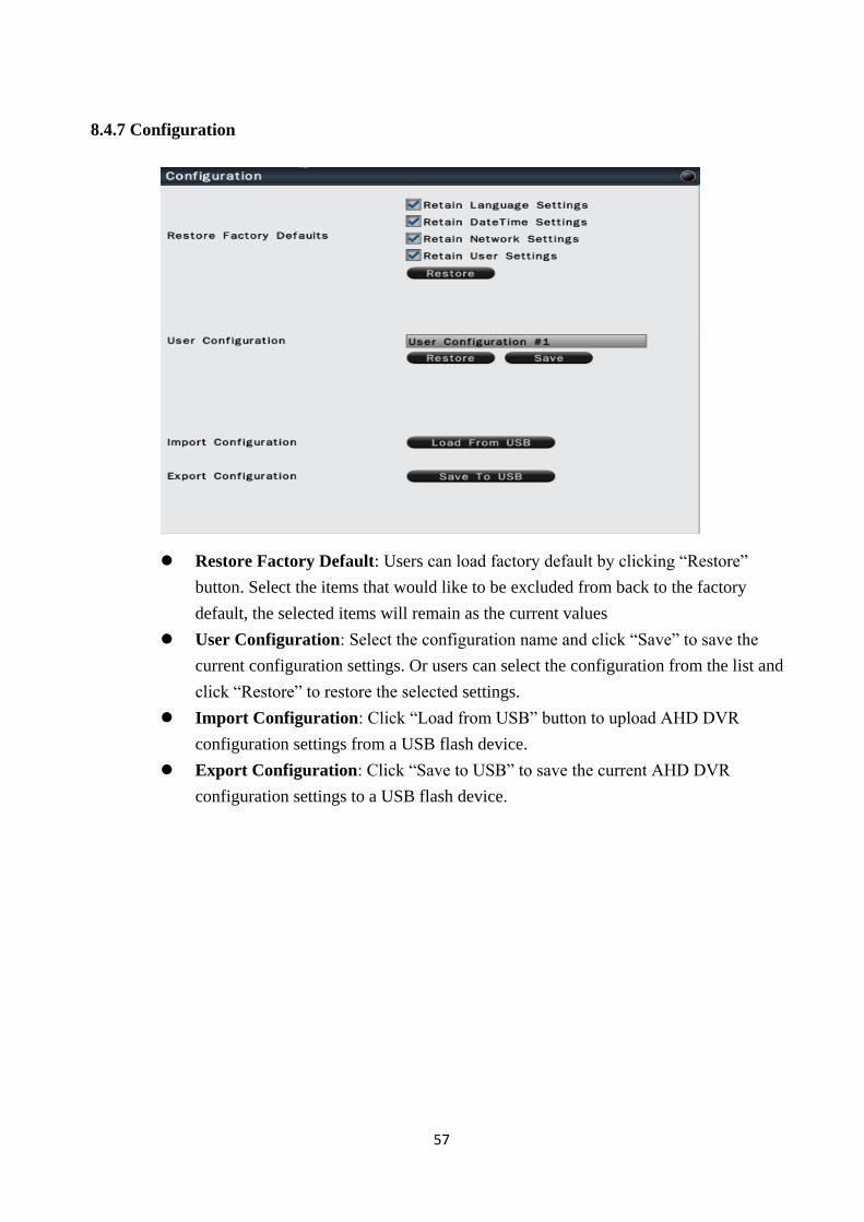
8.4.7 Configuration
Restore Factory Default: Users can load factory default by clicking “Restore”
button. Select the items that would like to be excluded from back to the factory
default, the selected items will remain as the current values
User Configuration: Select the configuration name and click “Save” to save the
current configuration settings. Or users can select the configuration from the list and
click “Restore” to restore the selected settings.
Import Configuration: Click “Load from USB” button to upload AHD DVR
configuration settings from a USB flash device.
Export Configuration: Click “Save to USB” to save the current AHD DVR
configuration settings to a USB flash device.
58
8.5 Information
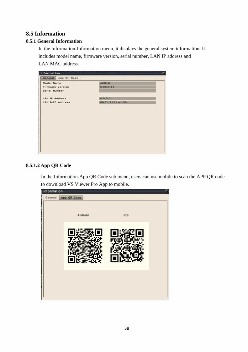
8.5.1 General Information
In the Information-Information menu, it displays the general system information. It
includes model name, firmware version, serial number, LAN IP address and
LAN MAC address.
8.5.1.2 App QR Code
In the Information-App QR Code sub menu, users can use mobile to scan the APP QR code
to download VS Viewer Pro App to mobile.
59
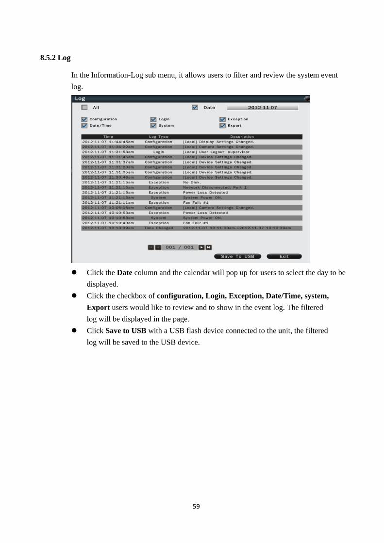
8.5.2 Log
In the Information-Log sub menu, it allows users to filter and review the system event
log.
Click the Date column and the calendar will pop up for users to select the day to be
displayed.
Click the checkbox of configuration, Login, Exception, Date/Time, system,
Export users would like to review and to show in the event log. The filtered
log will be displayed in the page.
Click Save to USB with a USB flash device connected to the unit, the filtered
log will be saved to the USB device.
60
9. Web Viewer Operation
9.1 Connecting to AHD DVR
Users can remote access the AHD DVR through Microsoft Internet Explorer to view
live/recorded video and manage the AHD DVR. Before accessing the web viewer, make
sure that the PC and AHD DVR are both connected to the internet and the network feature
is enabled.
For AHD DVR network setup, please refer to Chapter 8, 8.2.1.1 LAN Settings.
System Requirement
The following are minimum system requirements for web viewer.
Description Requirement
Operating System Windows XP/Vista/7/8
CPU Intel i3 or higher
Memory 4GB
Independent Graphic Card Minimum 128MB
Internet Explorer Version IE9, IE10, IE11
Note
Web Viewer is compatible with Internet Explorer (32 bit), Chrome, and Mozilla
Firefox.
To view the system in Internet Explorer:
1. It is suggested to select RUN as Administrator to ensure Web Viewer
complete functionality.
2. Please enter the IP address or DDNS address of NVR followed by the HTTP
Port. For
example, http://192.168.2.3 or http://089d21011a0ad.urDDNS.com.
3. Please allow to install ActiveX plugins to proceed to the next steps.
4. Enter the system user name and password to login the system.
9.2 Login
Open IE browser and input AHD DVR IP address in the address bar.
When accessing this feature for the first time, you will be prompted by the browser
to install Active X. The browser will pop up the below dialog for installation,
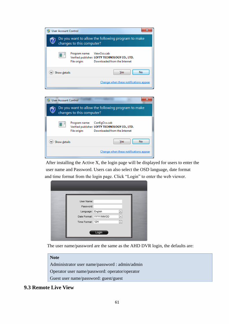
click“Yes” to accept and start the installation.
61
After installing the Active X, the login page will be displayed for users to enter the
user name and Password. Users can also select the OSD language, date format
and time format from the login page. Click “Login” to enter the web viewer.
The user name/password are the same as the AHD DVR login, the defaults are:
9.3 Remote Live View
Note
Administrator user name/password : admin/admin
Operator user name/password: operator/operator
Guest user name/password: guest/guest
62
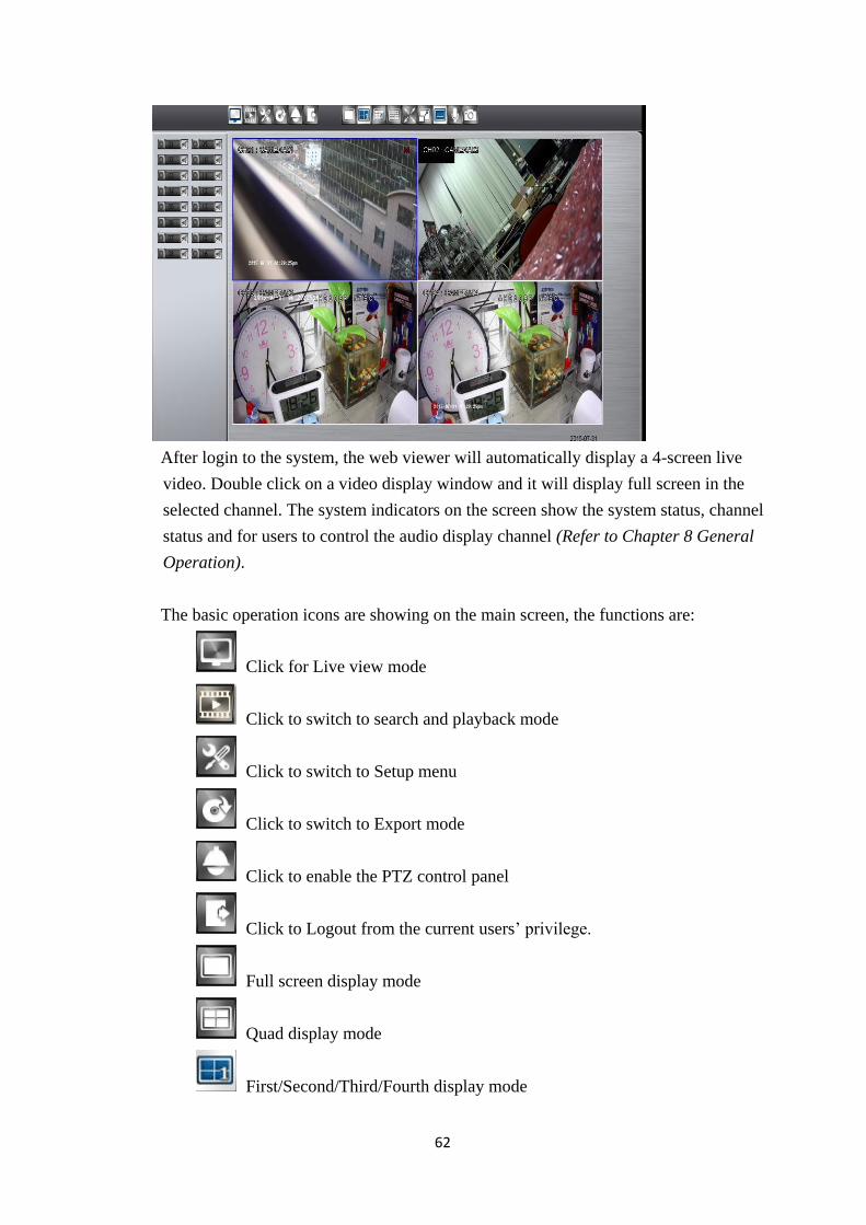
After login to the system, the web viewer will automatically display a 4-screen live
video. Double click on a video display window and it will display full screen in the
selected channel. The system indicators on the screen show the system status, channel
status and for users to control the audio display channel (Refer to Chapter 8 General
Operation).
The basic operation icons are showing on the main screen, the functions are:
Click for Live view mode
Click to switch to search and playback mode
Click to switch to Setup menu
Click to switch to Export mode
Click to enable the PTZ control panel
Click to Logout from the current users’ privilege.
Full screen display mode
Quad display mode
First/Second/Third/Fourth display mode
63
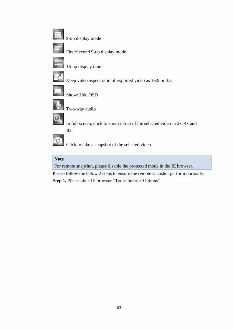
9-up display mode
First/Second 9-up display mode
16-up display mode
Keep video aspect ratio of exported video as 16:9 or 4:3
Show/Hide OSD
Two-way audio
In full screen, click to zoom in/out of the selected video in 2x, 4x and
8x.
Click to take a snapshot of the selected video.
Note
For remote snapshot, please disable the protected mode in the IE browser.
Please follow the below 2 steps to ensure the remote snapshot perform normally.
Step 1. Please click IE browser “Tools-Internet Options”.
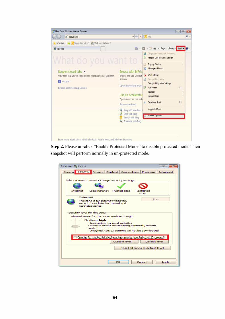
64
Step 2. Please un-click “Enable Protected Mode” to disable protected mode. Then
snapshot will perform normally in un-protected mode.
65
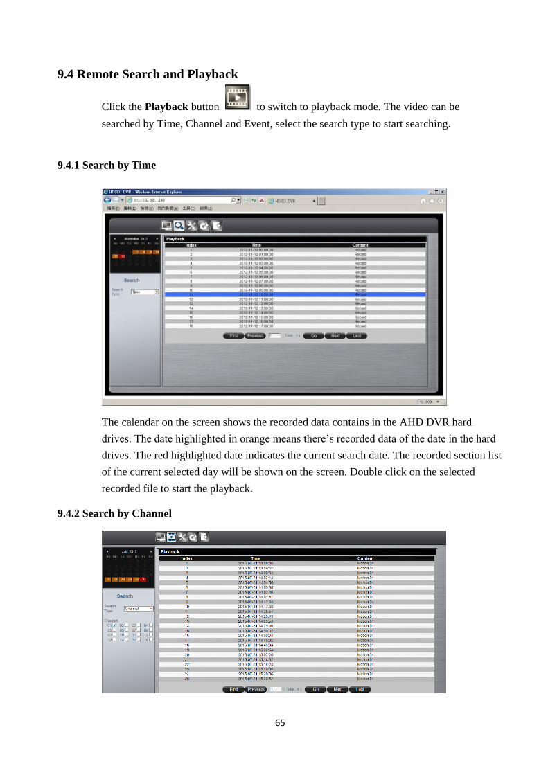
9.4 Remote Search and Playback
Click the Playback button to switch to playback mode. The video can be
searched by Time, Channel and Event, select the search type to start searching.
9.4.1 Search by Time
The calendar on the screen shows the recorded data contains in the AHD DVR hard
drives. The date highlighted in orange means there’s recorded data of the date in the hard
drives. The red highlighted date indicates the current search date. The recorded section list
of the current selected day will be shown on the screen. Double click on the selected
recorded file to start the playback.
9.4.2 Search by Channel
66
Search by Channel allows users to search the event video by channel. Select the date
from the calendar, and select the channel users would like to view. The event video
list of the selected channel will be shown on the screen.
Double click on the selected recorded file to start the playback.
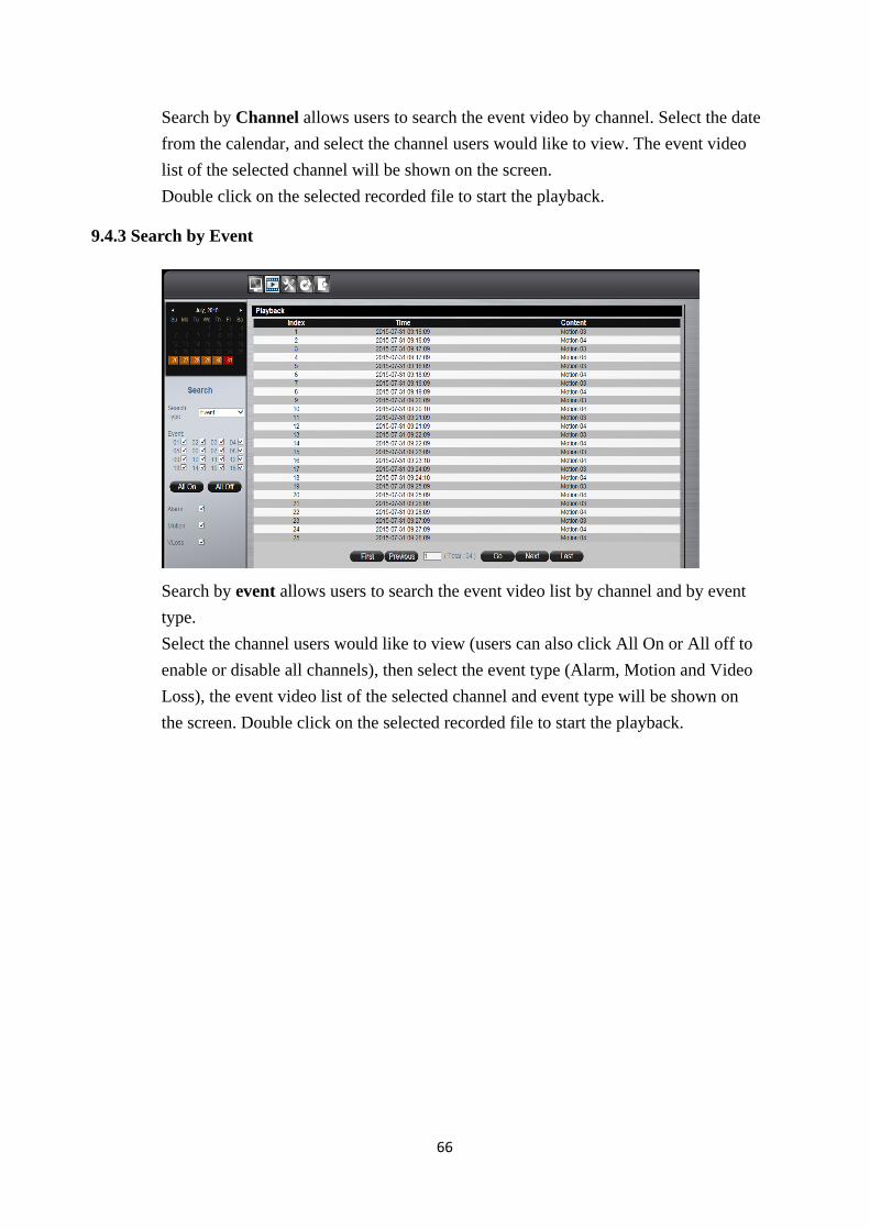
9.4.3 Search by Event
Search by event allows users to search the event video list by channel and by event
type.
Select the channel users would like to view (users can also click All On or All off to
enable or disable all channels), then select the event type (Alarm, Motion and Video
Loss), the event video list of the selected channel and event type will be shown on
the screen. Double click on the selected recorded file to start the playback.
67
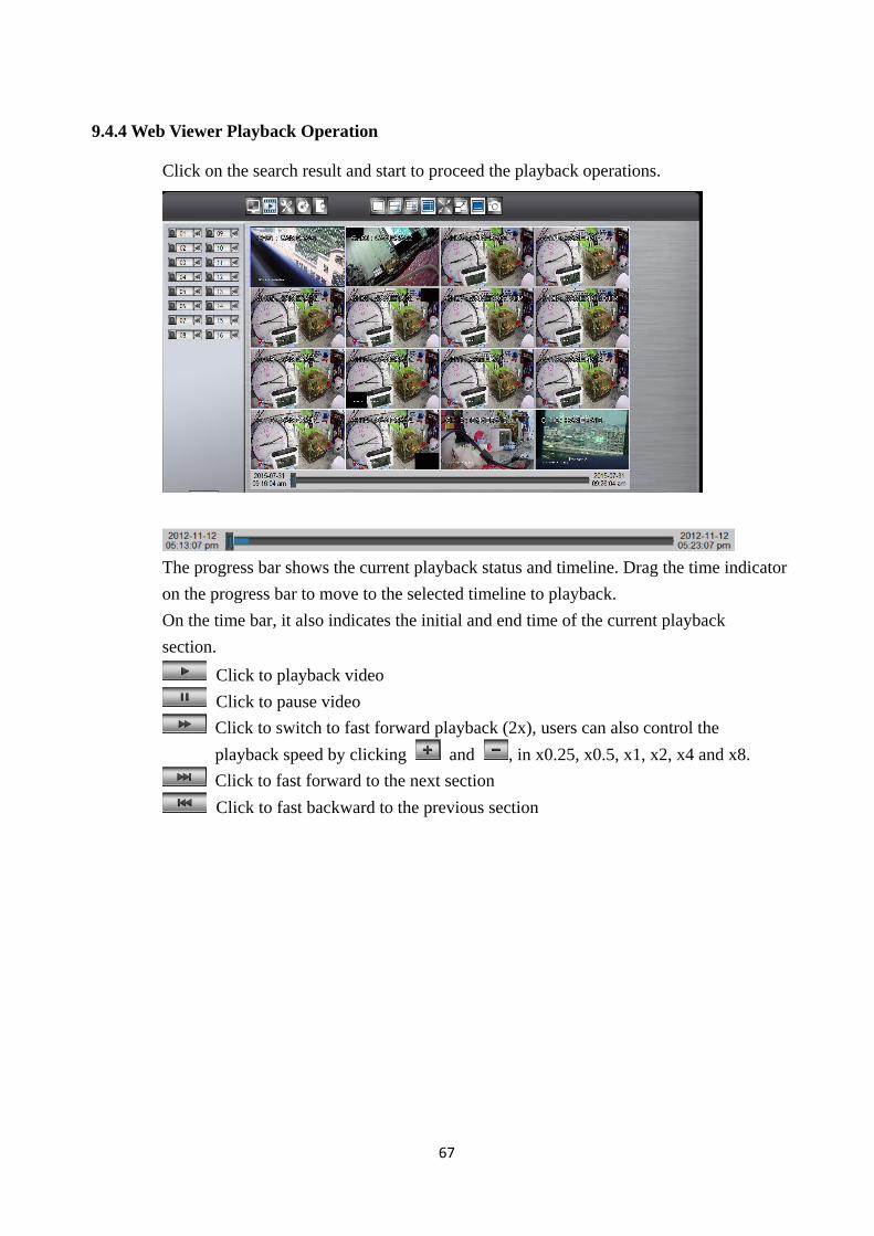
9.4.4 Web Viewer Playback Operation
Click on the search result and start to proceed the playback operations.
The progress bar shows the current playback status and timeline. Drag the time indicator
on the progress bar to move to the selected timeline to playback.
On the time bar, it also indicates the initial and end time of the current playback
section.
Click to playback video
Click to pause video
Click to switch to fast forward playback (2x), users can also control the
playback speed by clicking and , in x0.25, x0.5, x1, x2, x4 and x8.
Click to fast forward to the next section
Click to fast backward to the previous section
68
9.4.5 Web Viewer Setup Menu
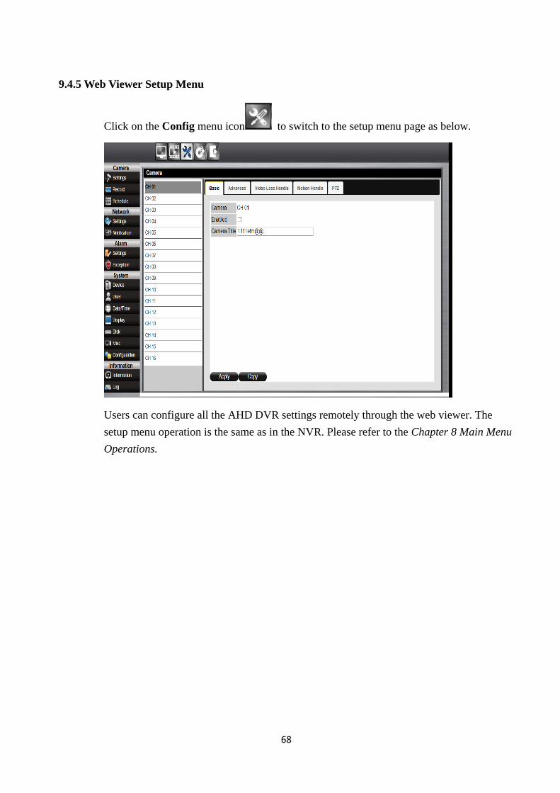
Click on the Config menu icon to switch to the setup menu page as below.
Users can configure all the AHD DVR settings remotely through the web viewer. The
setup menu operation is the same as in the NVR. Please refer to the Chapter 8 Main Menu
Operations.
69
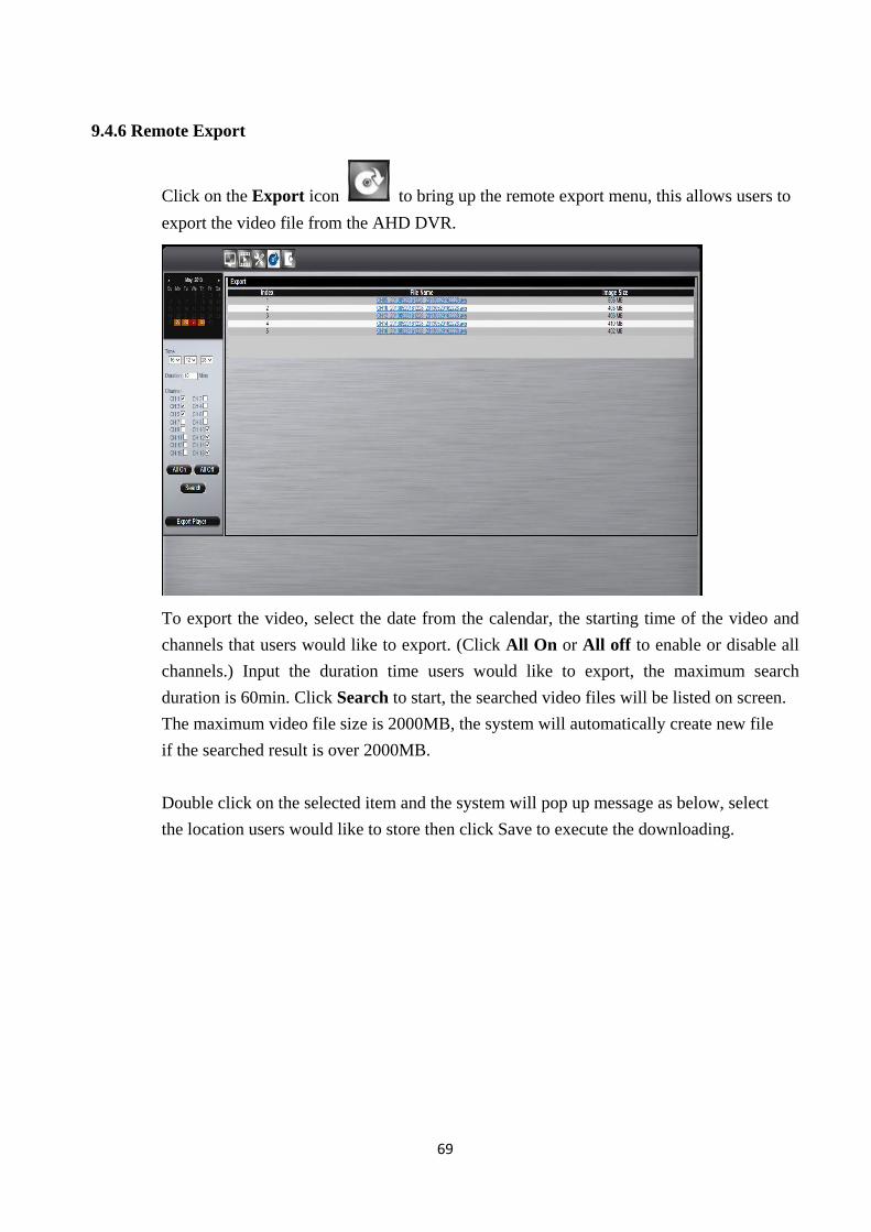
9.4.6 Remote Export
Click on the Export icon to bring up the remote export menu, this allows users to
export the video file from the AHD DVR.
To export the video, select the date from the calendar, the starting time of the video and
channels that users would like to export. (Click All On or All off to enable or disable all
channels.) Input the duration time users would like to export, the maximum search
duration is 60min. Click Search to start, the searched video files will be listed on screen.
The maximum video file size is 2000MB, the system will automatically create new file
if the searched result is over 2000MB.
Double click on the selected item and the system will pop up message as below, select
the location users would like to store then click Save to execute the downloading.
70
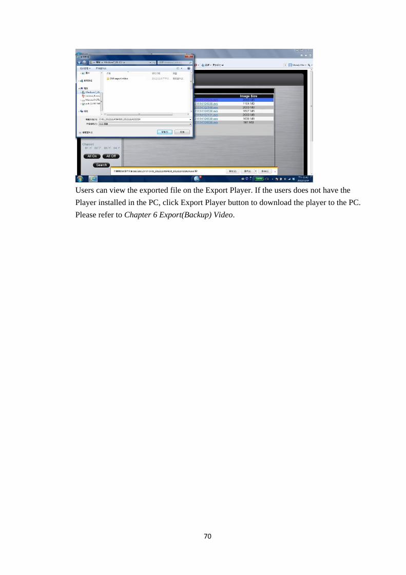
Users can view the exported file on the Export Player. If the users does not have the
Player installed in the PC, click Export Player button to download the player to the PC.
Please refer to Chapter 6 Export(Backup) Video.
71
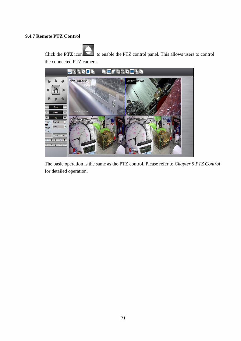
9.4.7 Remote PTZ Control
Click the PTZ icon to enable the PTZ control panel. This allows users to control
the connected PTZ camera.
The basic operation is the same as the PTZ control. Please refer to Chapter 5 PTZ Control
for detailed operation.
72
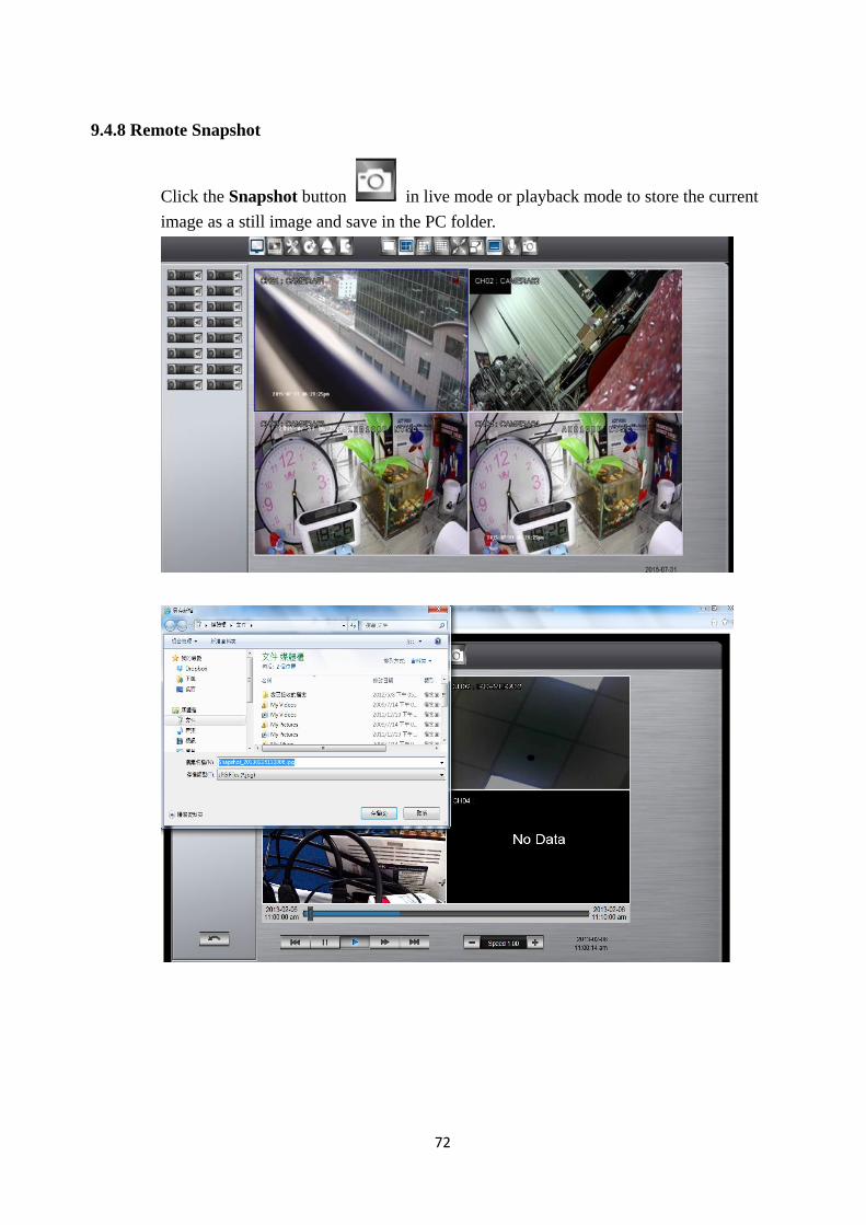
9.4.8 Remote Snapshot
Click the Snapshot button in live mode or playback mode to store the current
image as a still image and save in the PC folder.
73
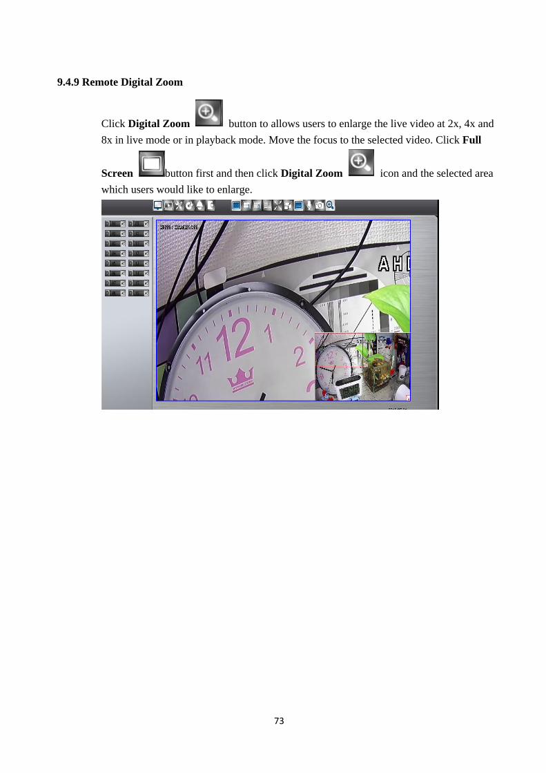
9.4.9 Remote Digital Zoom
Click Digital Zoom button to allows users to enlarge the live video at 2x, 4x and
8x in live mode or in playback mode. Move the focus to the selected video. Click Full
Screen button first and then click Digital Zoom icon and the selected area
which users would like to enlarge.
74
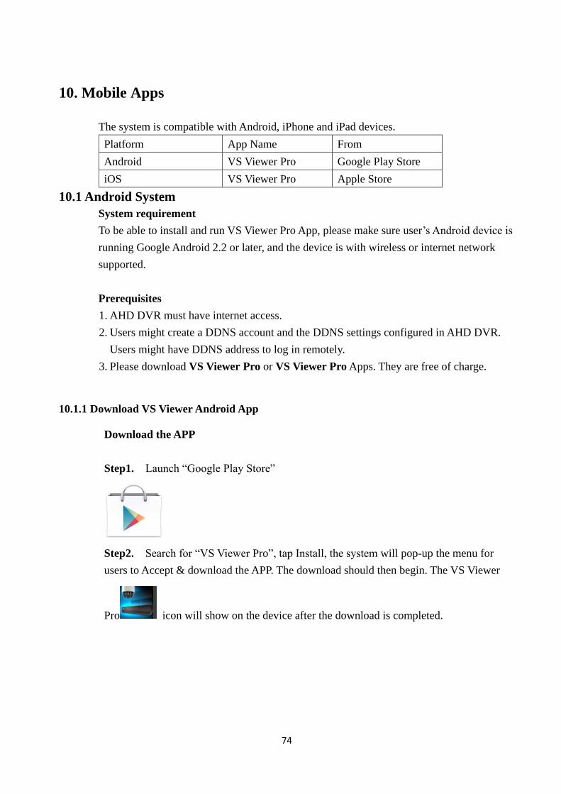
10. Mobile Apps
The system is compatible with Android, iPhone and iPad devices.
Platform App Name From
Android VS Viewer Pro Google Play Store
iOS VS Viewer Pro Apple Store
10.1 Android System
System requirement
To be able to install and run VS Viewer Pro App, please make sure user’s Android device is
running Google Android 2.2 or later, and the device is with wireless or internet network
supported.
Prerequisites
1. AHD DVR must have internet access.
2. Users might create a DDNS account and the DDNS settings configured in AHD DVR.
Users might have DDNS address to log in remotely.
3. Please download VS Viewer Pro or VS Viewer Pro Apps. They are free of charge.
10.1.1 Download VS Viewer Android App
Download the APP
Step1. Launch “Google Play Store”
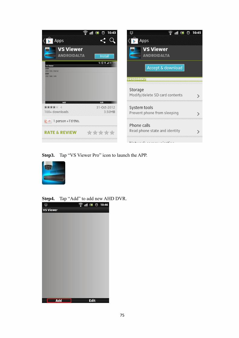
Step2. Search for “VS Viewer Pro”, tap Install, the system will pop-up the menu for
users to Accept & download the APP. The download should then begin. The VS Viewer
Pro icon will show on the device after the download is completed.
75
Step3. Tap “VS Viewer Pro” icon to launch the APP.
Step4. Tap “Add” to add new AHD DVR.
76
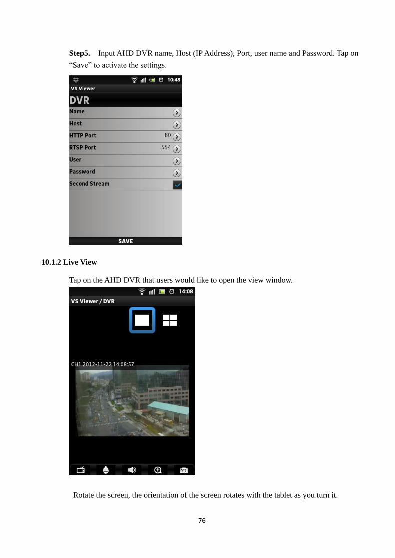
Step5. Input AHD DVR name, Host (IP Address), Port, user name and Password. Tap on
“Save” to activate the settings.
10.1.2 Live View
Tap on the AHD DVR that users would like to open the view window.
Rotate the screen, the orientation of the screen rotates with the tablet as you turn it.
77
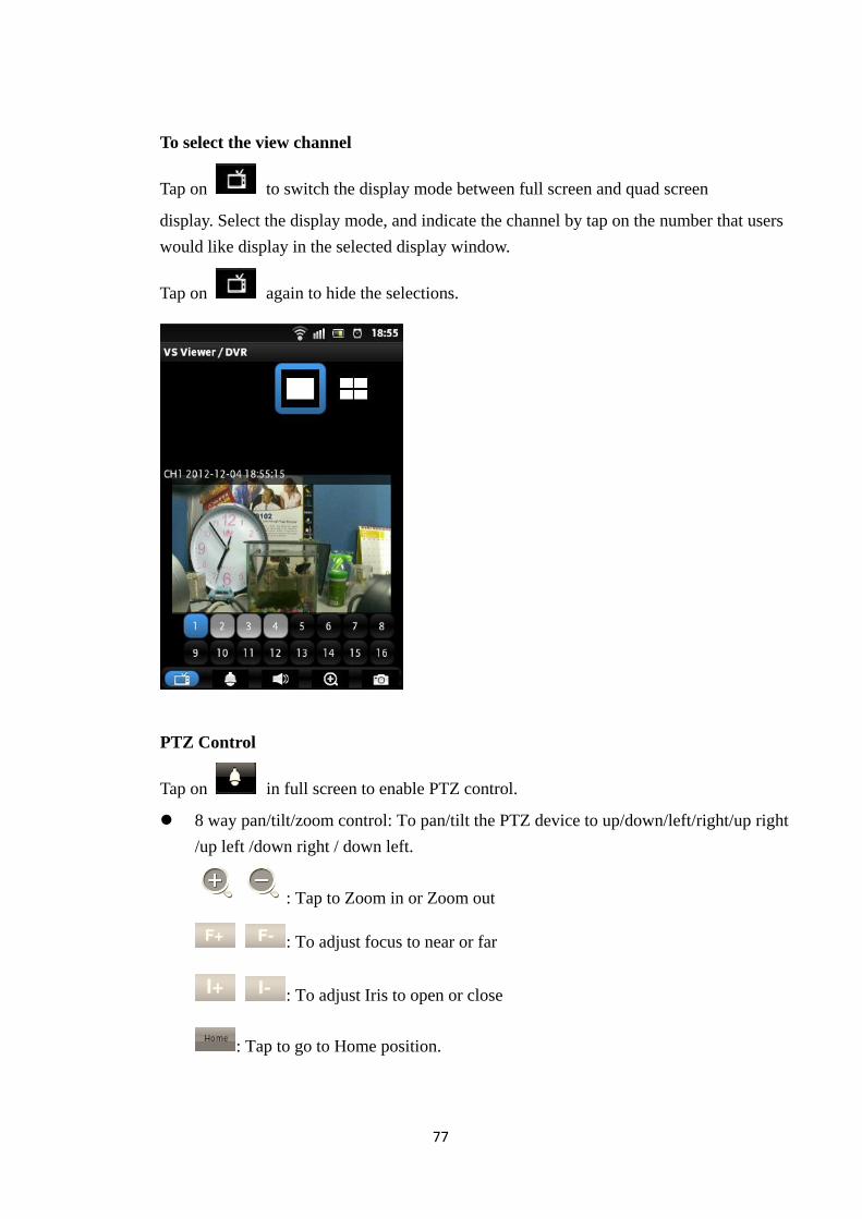
To select the view channel
Tap on to switch the display mode between full screen and quad screen
display. Select the display mode, and indicate the channel by tap on the number that users
would like display in the selected display window.
Tap on again to hide the selections.
PTZ Control
Tap on in full screen to enable PTZ control.
8 way pan/tilt/zoom control: To pan/tilt the PTZ device to up/down/left/right/up right
/up left /down right / down left.
: Tap to Zoom in or Zoom out
: To adjust focus to near or far
: To adjust Iris to open or close
: Tap to go to Home position.
78
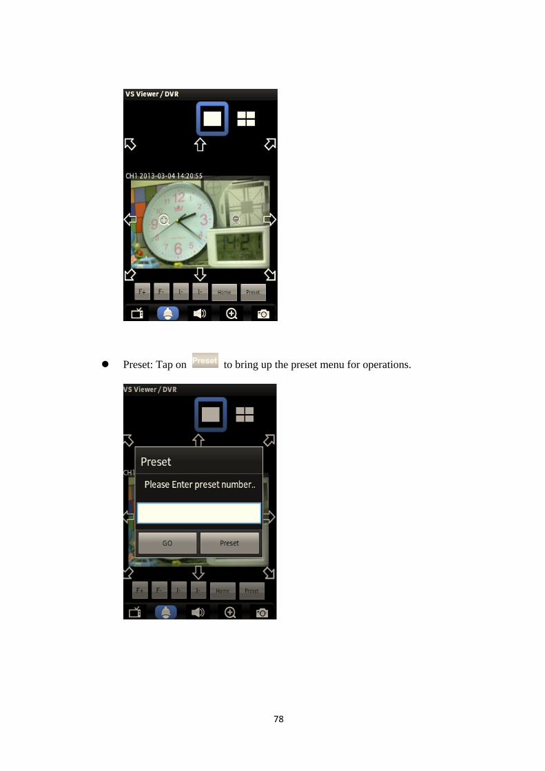
Preset: Tap on to bring up the preset menu for operations.
79
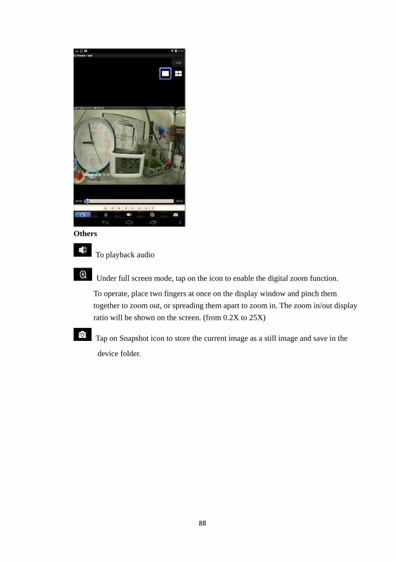
Others
To enable/disable audio display
Under full screen mode, tap on the icon to enable the digital zoom function.
To operate, place two fingers at once on the display window and pinch them
together to zoom out, or spreading them apart to zoom in. The zoom in/out display
ratio will be shown on the screen. (from 0.2X to 25X)
Tap on Snapshot icon to store the current image as a still image and save in the
device folder.
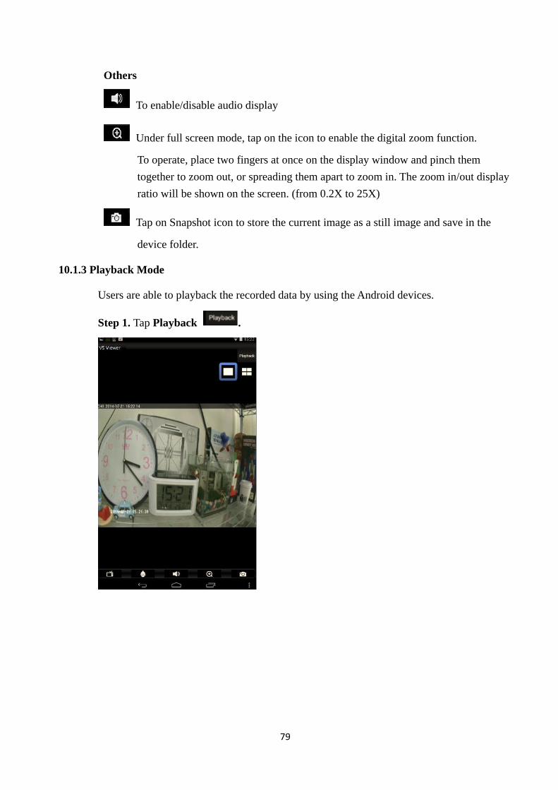
10.1.3 Playback Mode
Users are able to playback the recorded data by using the Android devices.
Step 1. Tap Playback .
80
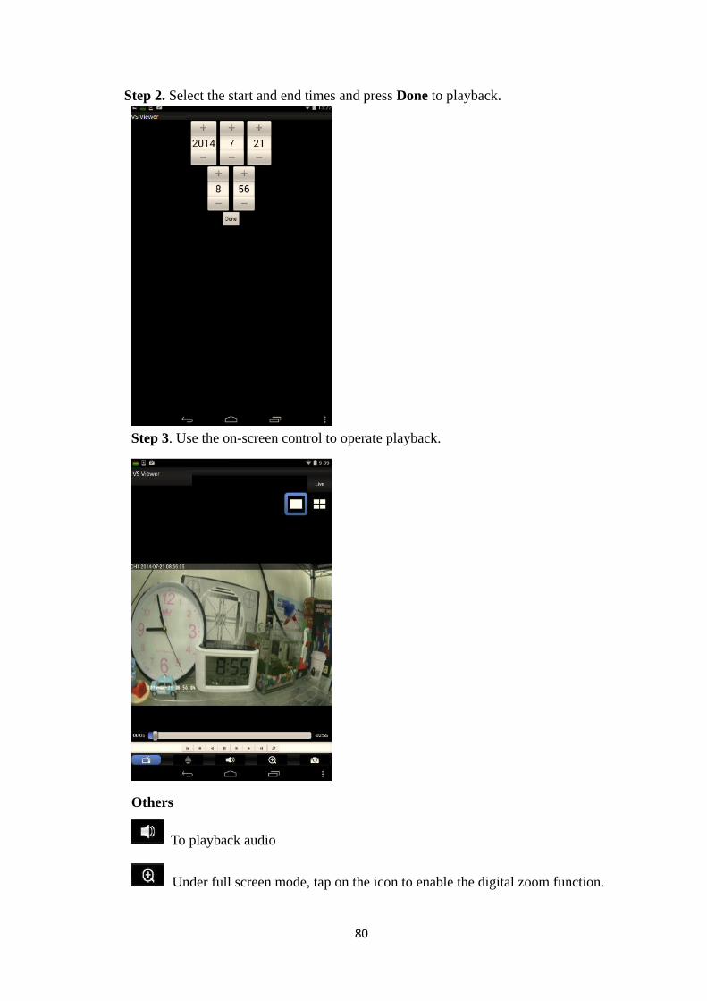
Step 2. Select the start and end times and press Done to playback.
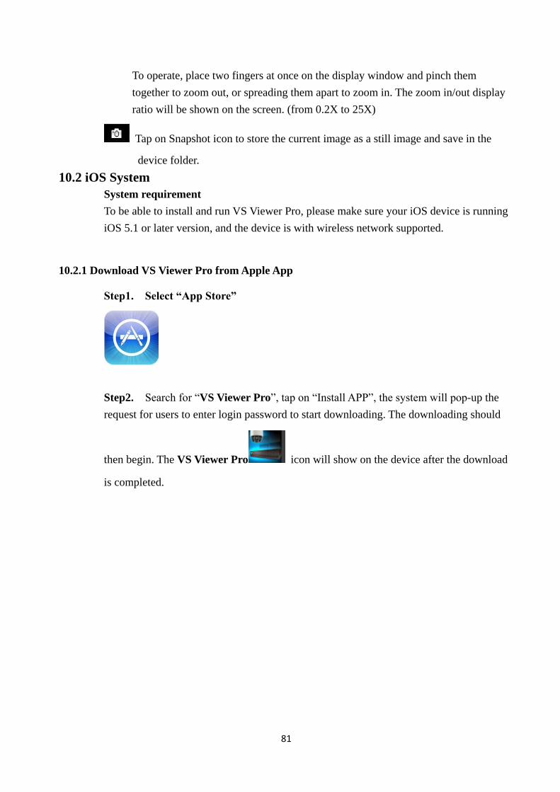
Step 3. Use the on-screen control to operate playback.
Others
To playback audio
Under full screen mode, tap on the icon to enable the digital zoom function.
81
To operate, place two fingers at once on the display window and pinch them
together to zoom out, or spreading them apart to zoom in. The zoom in/out display
ratio will be shown on the screen. (from 0.2X to 25X)
Tap on Snapshot icon to store the current image as a still image and save in the
device folder.
10.2 iOS System
System requirement
To be able to install and run VS Viewer Pro, please make sure your iOS device is running
iOS 5.1 or later version, and the device is with wireless network supported.
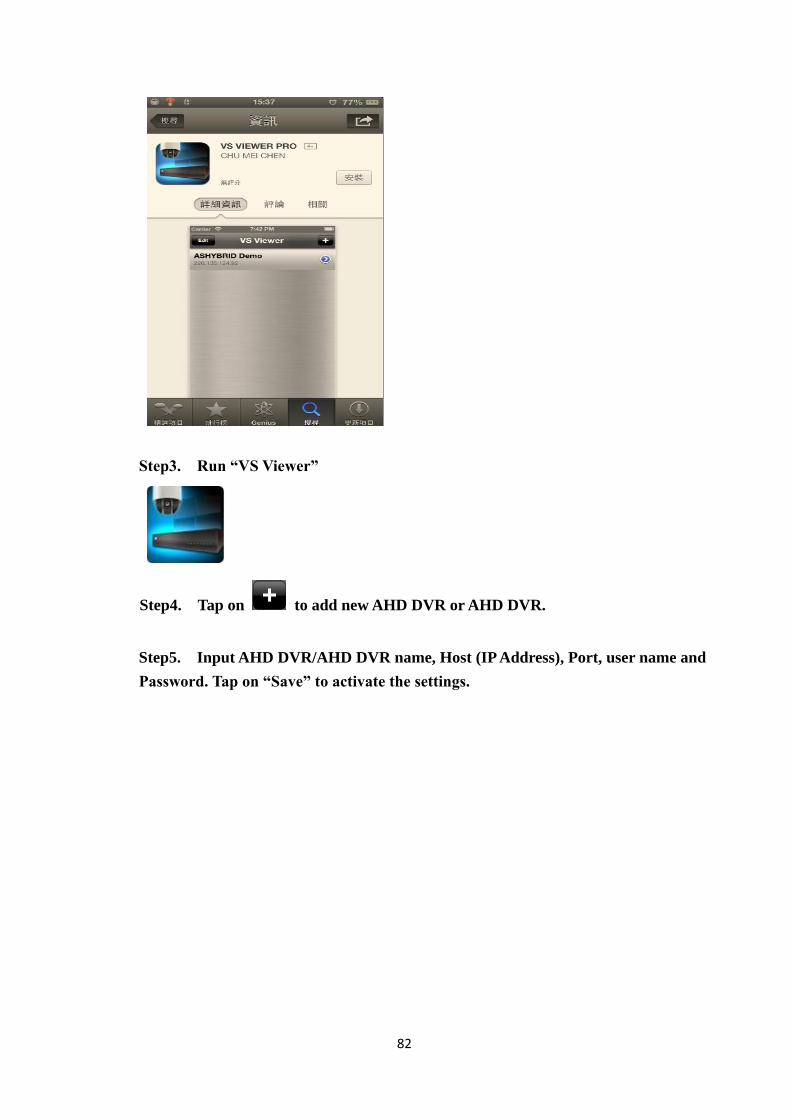
10.2.1 Download VS Viewer Pro from Apple App
Step1. Select “App Store”
Step2. Search for “VS Viewer Pro”, tap on “Install APP”, the system will pop-up the
request for users to enter login password to start downloading. The downloading should
then begin. The VS Viewer Pro icon will show on the device after the download
is completed.
82
Step3. Run “VS Viewer”
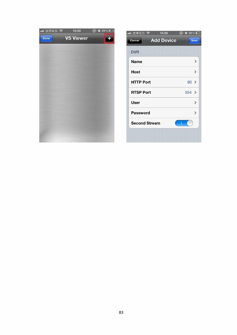
Step4. Tap on to add new AHD DVR or AHD DVR.
Step5. Input AHD DVR/AHD DVR name, Host (IP Address), Port, user name and
Password. Tap on “Save” to activate the settings.
83
84
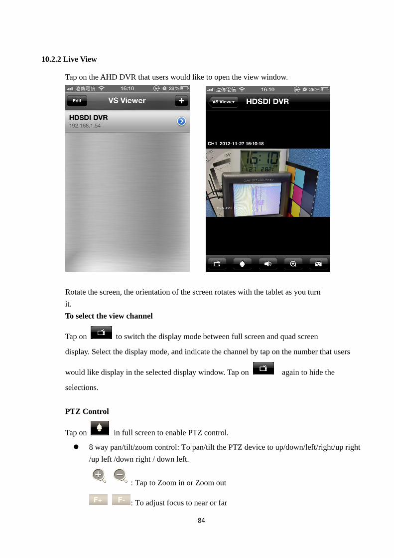
10.2.2 Live View
Tap on the AHD DVR that users would like to open the view window.
Rotate the screen, the orientation of the screen rotates with the tablet as you turn
it.
To select the view channel
Tap on to switch the display mode between full screen and quad screen
display. Select the display mode, and indicate the channel by tap on the number that users
would like display in the selected display window. Tap on again to hide the
selections.
PTZ Control
Tap on in full screen to enable PTZ control.
8 way pan/tilt/zoom control: To pan/tilt the PTZ device to up/down/left/right/up right
/up left /down right / down left.
: Tap to Zoom in or Zoom out
: To adjust focus to near or far
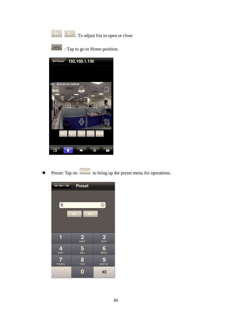
85
: To adjust Iris to open or close
: Tap to go to Home position.
Preset: Tap on to bring up the preset menu for operations.
86
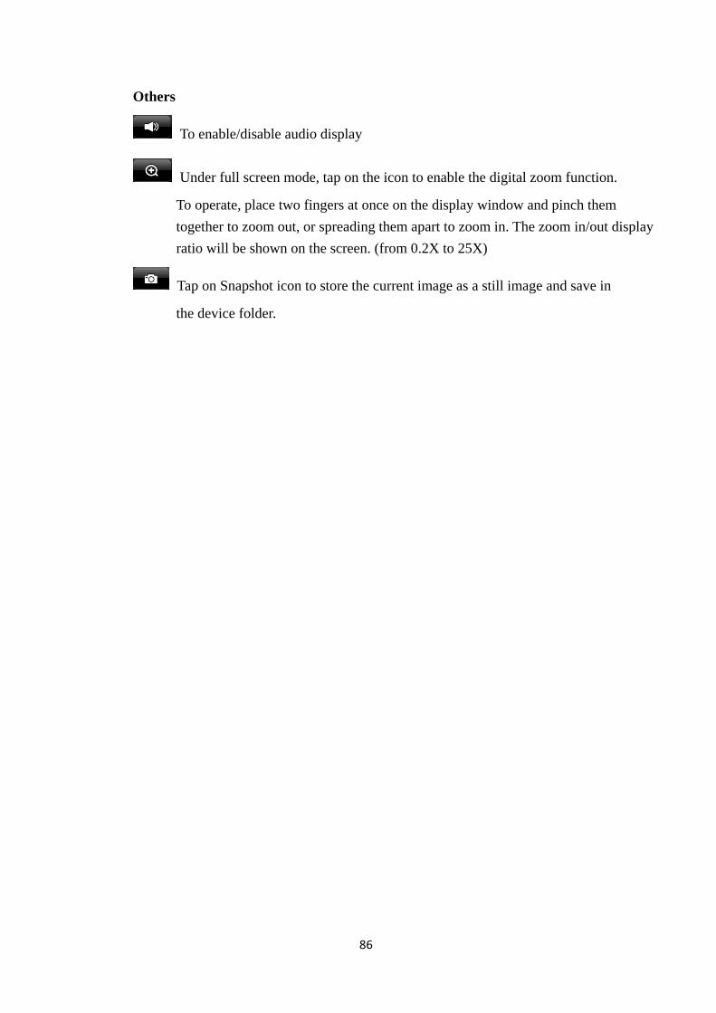
Others
To enable/disable audio display
Under full screen mode, tap on the icon to enable the digital zoom function.
To operate, place two fingers at once on the display window and pinch them
together to zoom out, or spreading them apart to zoom in. The zoom in/out display
ratio will be shown on the screen. (from 0.2X to 25X)
Tap on Snapshot icon to store the current image as a still image and save in
the device folder.
87
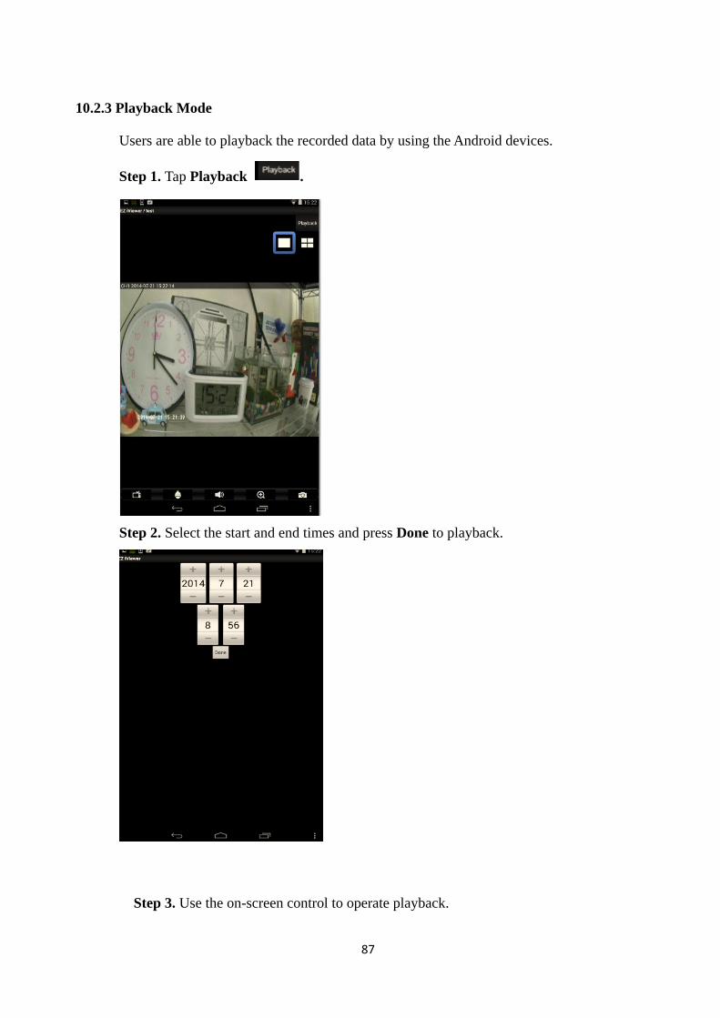
10.2.3 Playback Mode
Users are able to playback the recorded data by using the Android devices.
Step 1. Tap Playback .
Step 2. Select the start and end times and press Done to playback.
Step 3. Use the on-screen control to operate playback.
88
Others
To playback audio
Under full screen mode, tap on the icon to enable the digital zoom function.
To operate, place two fingers at once on the display window and pinch them
together to zoom out, or spreading them apart to zoom in. The zoom in/out display
ratio will be shown on the screen. (from 0.2X to 25X)
Tap on Snapshot icon to store the current image as a still image and save in the
device folder.
89
11. CMS Pro Operation
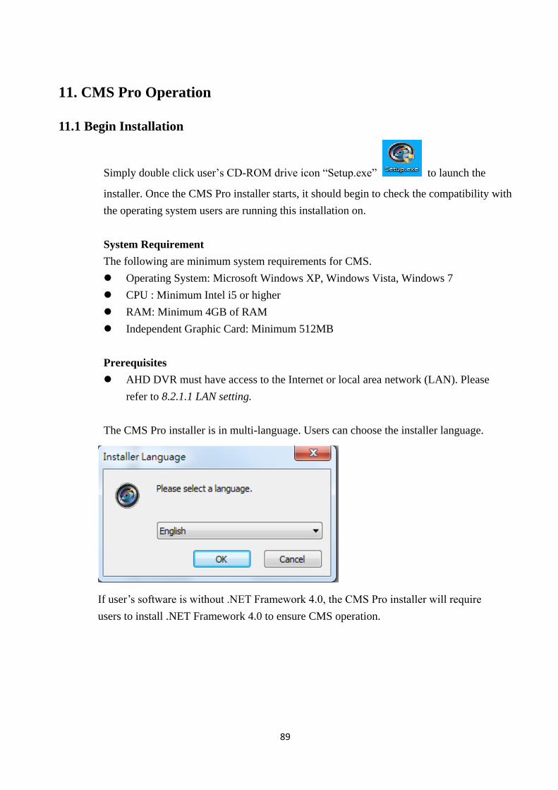
11.1 Begin Installation
Simply double click user’s CD-ROM drive icon “Setup.exe” to launch the
installer. Once the CMS Pro installer starts, it should begin to check the compatibility with
the operating system users are running this installation on.
System Requirement
The following are minimum system requirements for CMS.
Operating System: Microsoft Windows XP, Windows Vista, Windows 7
CPU : Minimum Intel i5 or higher
RAM: Minimum 4GB of RAM
Independent Graphic Card: Minimum 512MB
Prerequisites
AHD DVR must have access to the Internet or local area network (LAN). Please
refer to 8.2.1.1 LAN setting.
The CMS Pro installer is in multi-language. Users can choose the installer language.
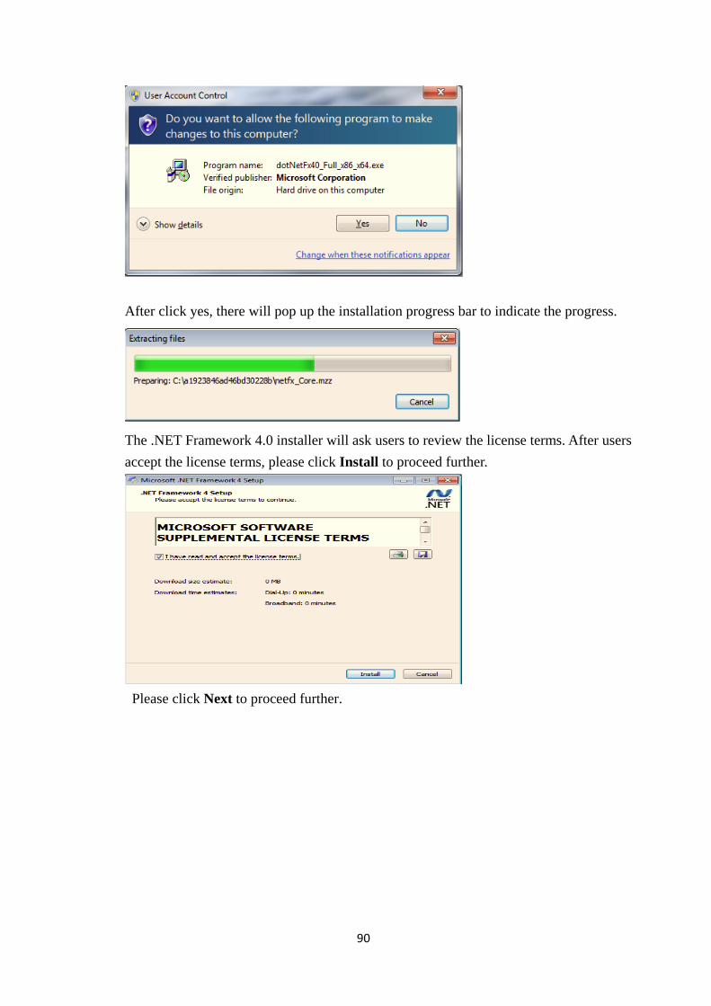
If user’s software is without .NET Framework 4.0, the CMS Pro installer will require
users to install .NET Framework 4.0 to ensure CMS operation.
90
After click yes, there will pop up the installation progress bar to indicate the progress.
The .NET Framework 4.0 installer will ask users to review the license terms. After users
accept the license terms, please click Install to proceed further.
Please click Next to proceed further.
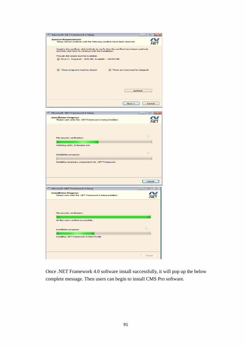
91
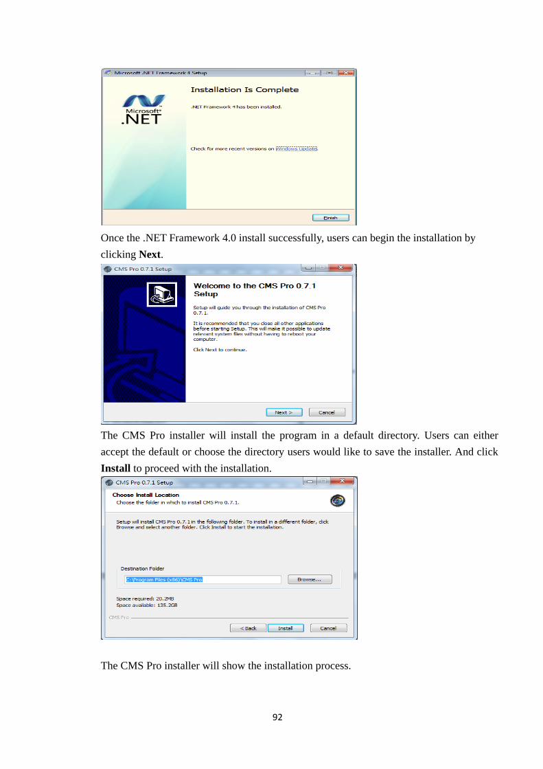
Once .NET Framework 4.0 software install successfully, it will pop up the below
complete message. Then users can begin to install CMS Pro software.
92
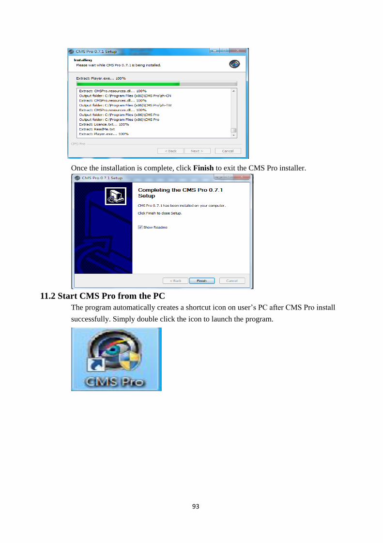
Once the .NET Framework 4.0 install successfully, users can begin the installation by
clicking Next.
The CMS Pro installer will install the program in a default directory. Users can either
accept the default or choose the directory users would like to save the installer. And click
Install to proceed with the installation.
The CMS Pro installer will show the installation process.
93
Once the installation is complete, click Finish to exit the CMS Pro installer.
11.2 Start CMS Pro from the PC
The program automatically creates a shortcut icon on user’s PC after CMS Pro install
successfully. Simply double click the icon to launch the program.
94
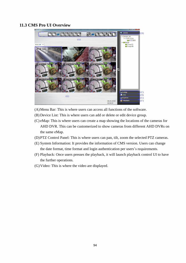
11.3 CMS Pro UI Overview
(A) Menu Bar: This is where users can access all functions of the software.
(B) Device List: This is where users can add or delete or edit device group.
(C) eMap: This is where users can create a map showing the locations of the cameras for
AHD DVR. This can be customerized to show cameras from different AHD DVRs on
the same eMap.
(D) PTZ Control Panel: This is where users can pan, tilt, zoom the selected PTZ cameras.
(E) System Information: It provides the information of CMS version. Users can change
the date format, time format and login authentication per users’s requirements.
(F) Playback: Once users presses the playback, it will launch playback control UI to have
the further operations.
(G) Video: This is where the video are displayed.
95
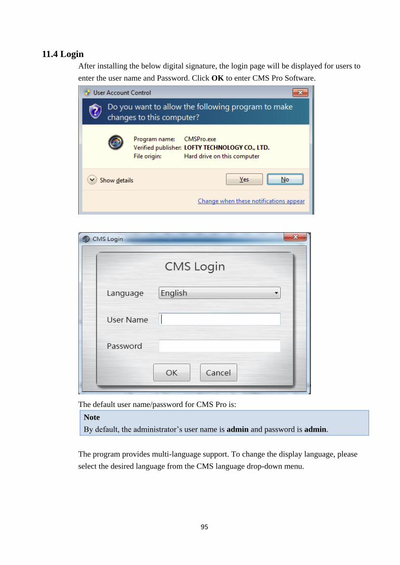
11.4 Login
After installing the below digital signature, the login page will be displayed for users to
enter the user name and Password. Click OK to enter CMS Pro Software.
The default user name/password for CMS Pro is:
Note
By default, the administrator’s user name is admin and password is admin.
The program provides multi-language support. To change the display language, please
select the desired language from the CMS language drop-down menu.
96
11.5 Add Device to CMS Pro
The main purpose of the CMS Pro software is to manage multiple devices. Users would
need to tell the program which device Users needs to manage. Users do that by adding one
or more devices through the device list.
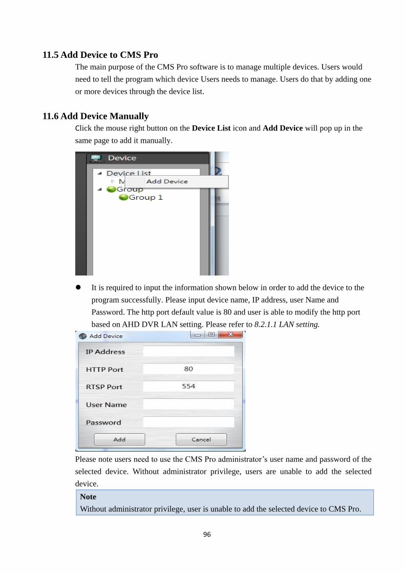
11.6 Add Device Manually
Click the mouse right button on the Device List icon and Add Device will pop up in the
same page to add it manually.
It is required to input the information shown below in order to add the device to the
program successfully. Please input device name, IP address, user Name and
Password. The http port default value is 80 and user is able to modify the http port
based on AHD DVR LAN setting. Please refer to 8.2.1.1 LAN setting.
Please note users need to use the CMS Pro administrator’s user name and password of the
selected device. Without administrator privilege, users are unable to add the selected
device.
Note
Without administrator privilege, user is unable to add the selected device to CMS Pro.
97
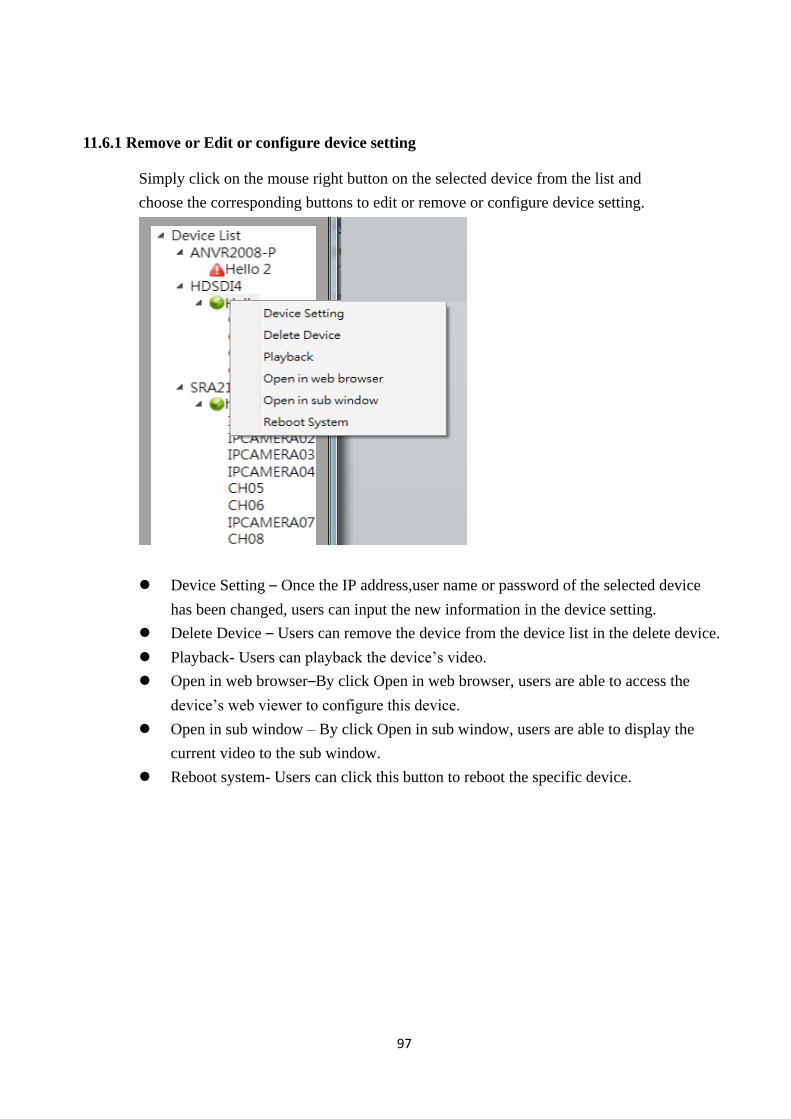
11.6.1 Remove or Edit or configure device setting
Simply click on the mouse right button on the selected device from the list and
choose the corresponding buttons to edit or remove or configure device setting.
Device Setting – Once the IP address,user name or password of the selected device
has been changed, users can input the new information in the device setting.
Delete Device – Users can remove the device from the device list in the delete device.
Playback- Users can playback the device’s video.
Open in web browser–By click Open in web browser, users are able to access the
device’s web viewer to configure this device.
Open in sub window – By click Open in sub window, users are able to display the
current video to the sub window.
Reboot system- Users can click this button to reboot the specific device.
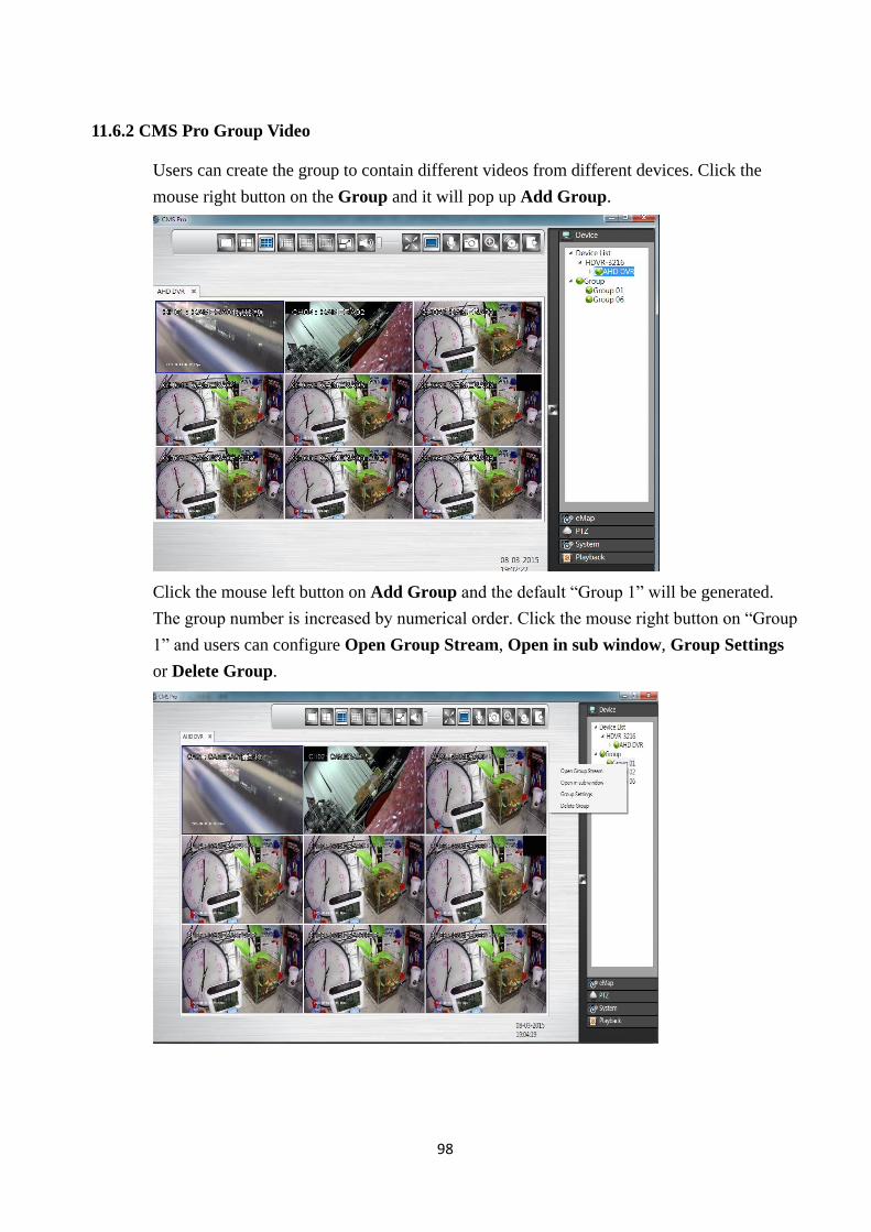
98
11.6.2 CMS Pro Group Video
Users can create the group to contain different videos from different devices. Click the
mouse right button on the Group and it will pop up Add Group.
Click the mouse left button on Add Group and the default “Group 1” will be generated.
The group number is increased by numerical order. Click the mouse right button on “Group
1” and users can configure Open Group Stream, Open in sub window, Group Settings
or Delete Group.
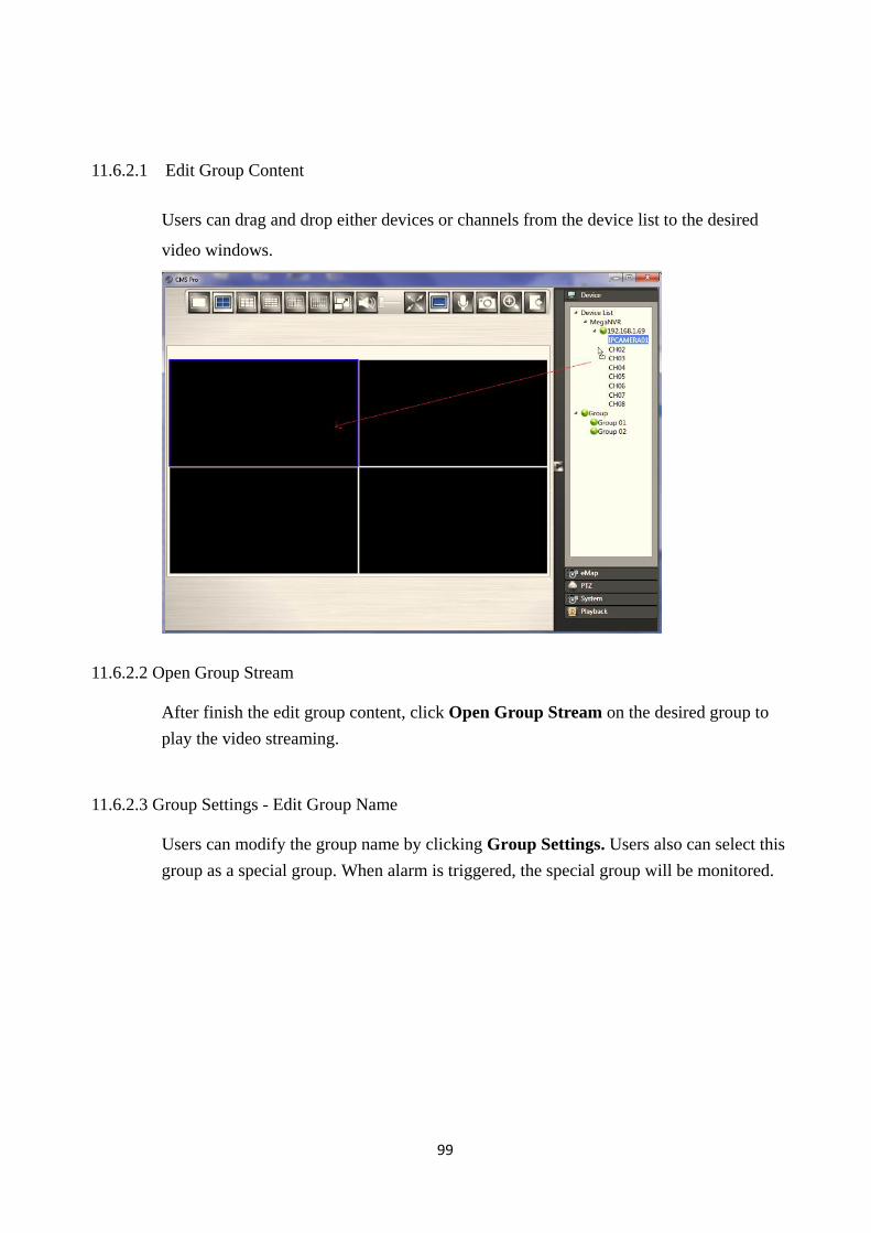
99
11.6.2.1 Edit Group Content
Users can drag and drop either devices or channels from the device list to the desired
video windows.
11.6.2.2 Open Group Stream
After finish the edit group content, click Open Group Stream on the desired group to
play the video streaming.
11.6.2.3 Group Settings - Edit Group Name
Users can modify the group name by clicking Group Settings. Users also can select this
group as a special group. When alarm is triggered, the special group will be monitored.
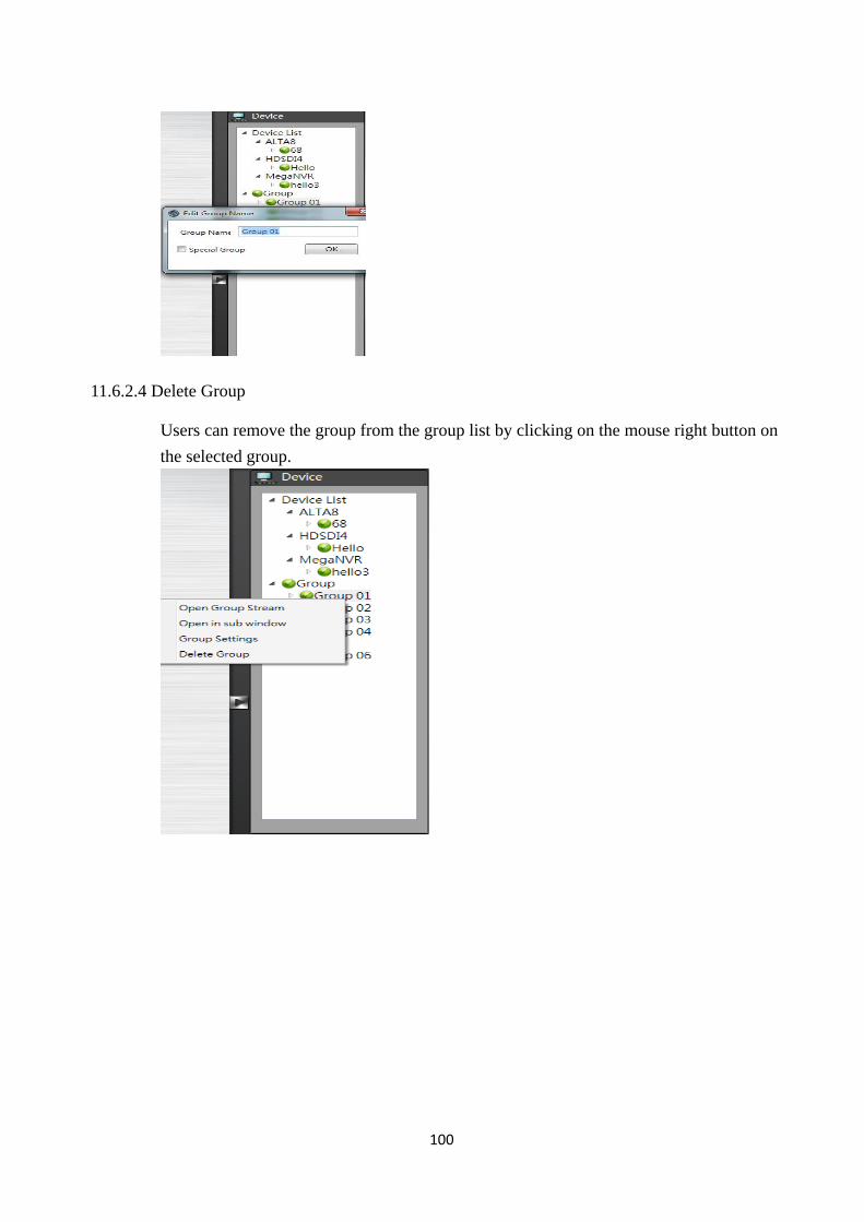
100
11.6.2.4 Delete Group
Users can remove the group from the group list by clicking on the mouse right button on
the selected group.
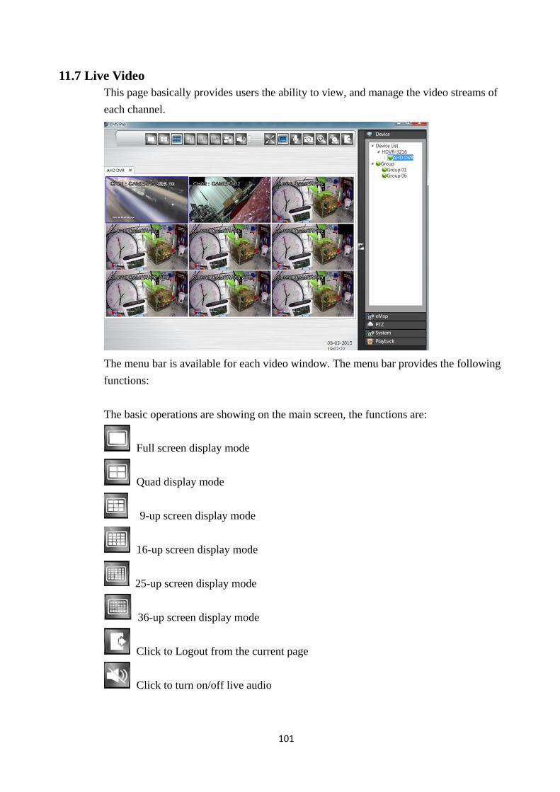
101
11.7 Live Video
This page basically provides users the ability to view, and manage the video streams of
each channel.
The menu bar is available for each video window. The menu bar provides the following
functions:
The basic operations are showing on the main screen, the functions are:
Full screen display mode
Quad display mode
9-up screen display mode
16-up screen display mode
25-up screen display mode
36-up screen display mode
Click to Logout from the current page
Click to turn on/off live audio
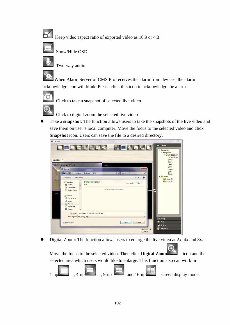
102
Keep video aspect ratio of exported video as 16:9 or 4:3
Show/Hide OSD
Two-way audio
When Alarm Server of CMS Pro receives the alarm from devices, the alarm
acknowledge icon will blink. Please click this icon to acknowledge the alarm.
Click to take a snapshot of selected live video
Click to digital zoom the selected live video
Take a snapshot: The function allows users to take the snapshots of the live video and
save them on user’s local computer. Move the focus to the selected video and click
Snapshot icon. Users can save the file to a desired directory.
Digital Zoom: The function allows users to enlarge the live video at 2x, 4x and 8x.
Move the focus to the selected video. Then click Digital Zoom icon and the
selected area which users would like to enlarge. This function also can work in
1-up , 4-up , 9-up and 16-up screen display mode.
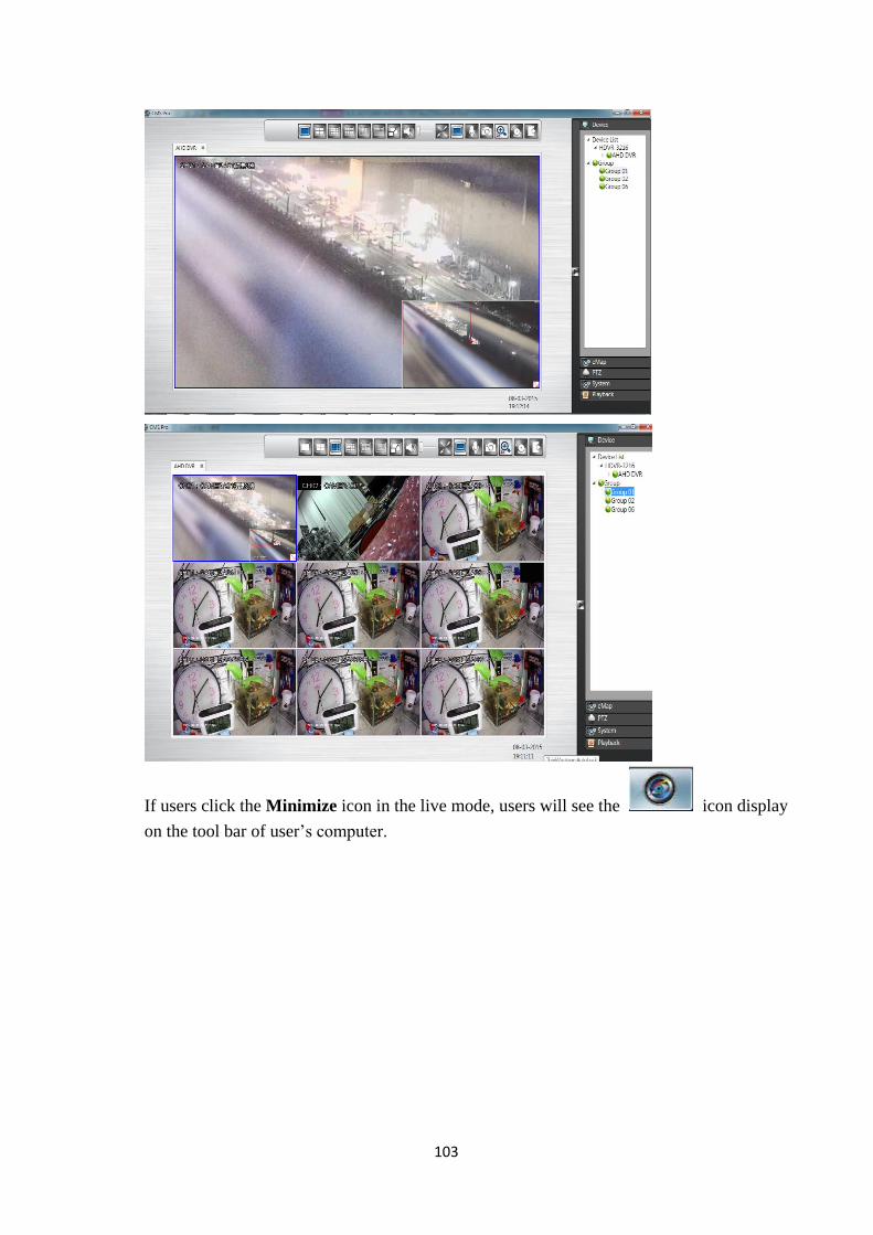
103
If users click the Minimize icon in the live mode, users will see the icon display
on the tool bar of user’s computer.
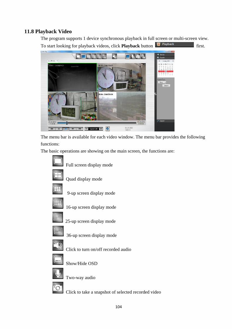
104
11.8 Playback Video
The program supports 1 device synchronous playback in full screen or multi-screen view.
To start looking for playback videos, click Playback button first.
The menu bar is available for each video window. The menu bar provides the following
functions:
The basic operations are showing on the main screen, the functions are:
Full screen display mode
Quad display mode
9-up screen display mode
16-up screen display mode
25-up screen display mode
36-up screen display mode
Click to turn on/off recorded audio
Show/Hide OSD
Two-way audio
Click to take a snapshot of selected recorded video
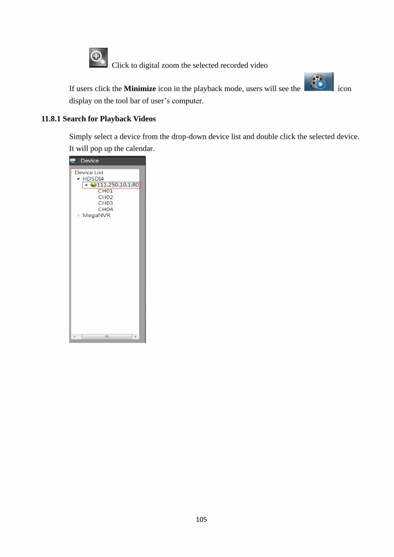
105
Click to digital zoom the selected recorded video
If users click the Minimize icon in the playback mode, users will see the icon
display on the tool bar of user’s computer.
11.8.1 Search for Playback Videos
Simply select a device from the drop-down device list and double click the selected device.
It will pop up the calendar.
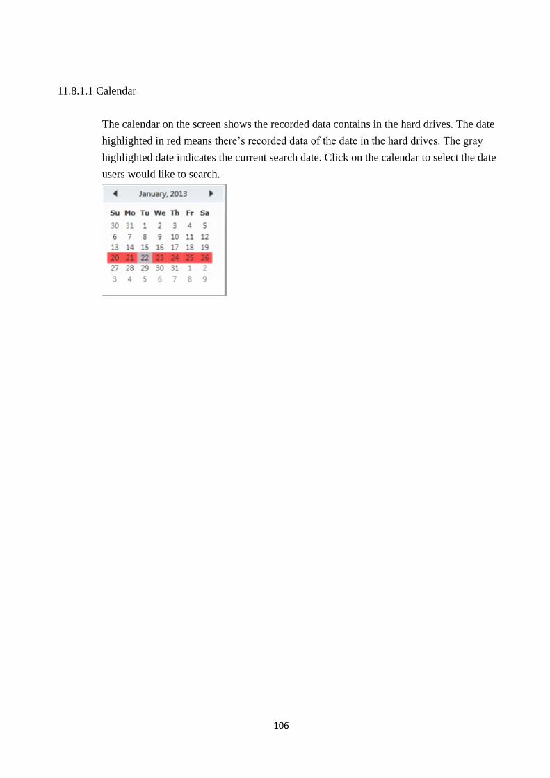
106
11.8.1.1 Calendar
The calendar on the screen shows the recorded data contains in the hard drives. The date
highlighted in red means there’s recorded data of the date in the hard drives. The gray
highlighted date indicates the current search date. Click on the calendar to select the date
users would like to search.
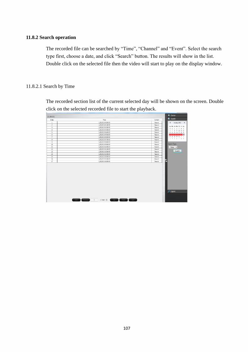
107
11.8.2 Search operation
The recorded file can be searched by “Time”, “Channel” and “Event”. Select the search
type first, choose a date, and click “Search” button. The results will show in the list.
Double click on the selected file then the video will start to play on the display window.
11.8.2.1 Search by Time
The recorded section list of the current selected day will be shown on the screen. Double
click on the selected recorded file to start the playback.
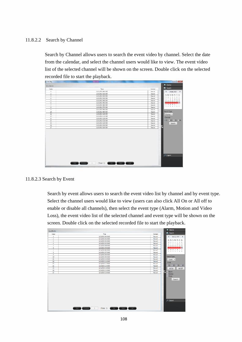
108
11.8.2.2 Search by Channel
Search by Channel allows users to search the event video by channel. Select the date
from the calendar, and select the channel users would like to view. The event video
list of the selected channel will be shown on the screen. Double click on the selected
recorded file to start the playback.
11.8.2.3 Search by Event
Search by event allows users to search the event video list by channel and by event type.
Select the channel users would like to view (users can also click All On or All off to
enable or disable all channels), then select the event type (Alarm, Motion and Video
Loss), the event video list of the selected channel and event type will be shown on the
screen. Double click on the selected recorded file to start the playback.
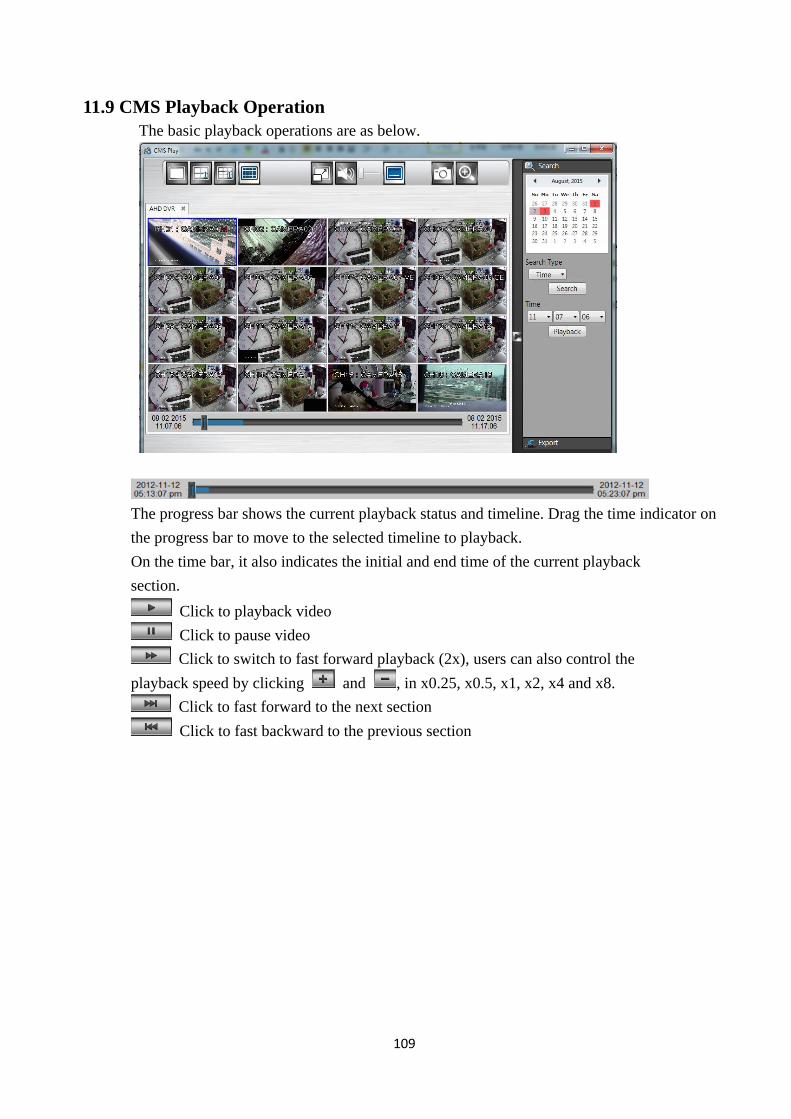
109
11.9 CMS Playback Operation
The basic playback operations are as below.
The progress bar shows the current playback status and timeline. Drag the time indicator on
the progress bar to move to the selected timeline to playback.
On the time bar, it also indicates the initial and end time of the current playback
section.
Click to playback video
Click to pause video
Click to switch to fast forward playback (2x), users can also control the
playback speed by clicking and , in x0.25, x0.5, x1, x2, x4 and x8.
Click to fast forward to the next section
Click to fast backward to the previous section
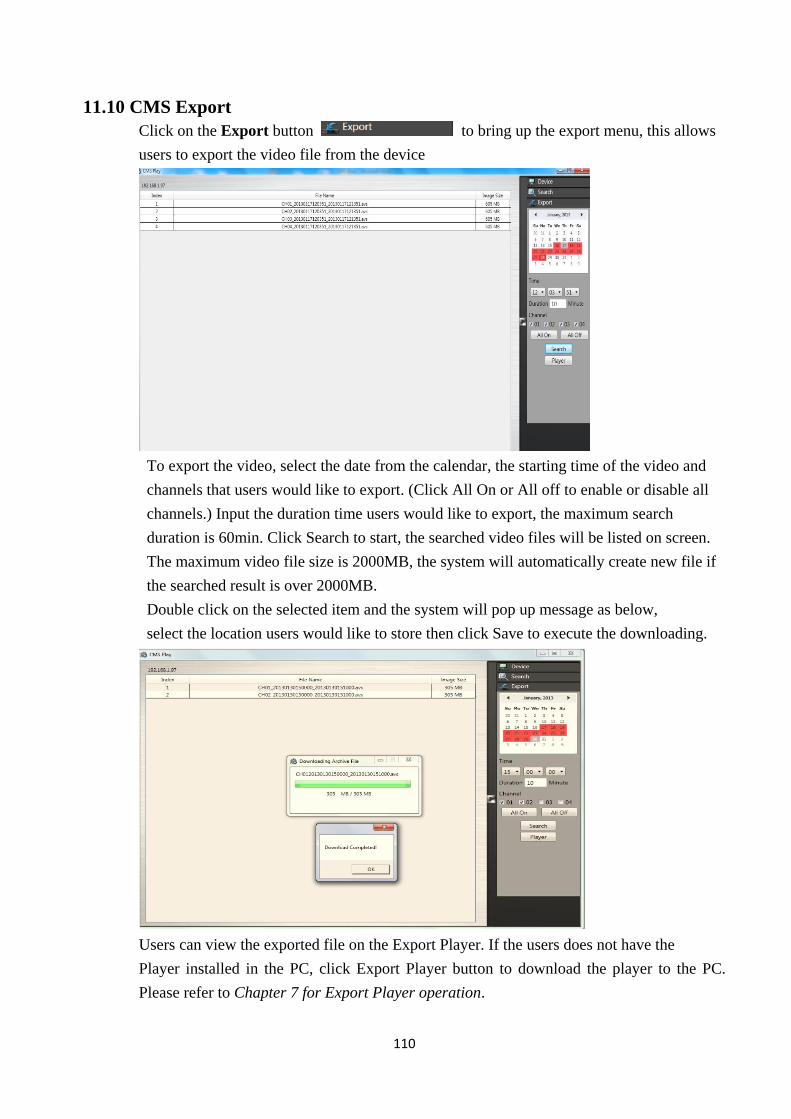
110
11.10 CMS Export
Click on the Export button to bring up the export menu, this allows
users to export the video file from the device
To export the video, select the date from the calendar, the starting time of the video and
channels that users would like to export. (Click All On or All off to enable or disable all
channels.) Input the duration time users would like to export, the maximum search
duration is 60min. Click Search to start, the searched video files will be listed on screen.
The maximum video file size is 2000MB, the system will automatically create new file if
the searched result is over 2000MB.
Double click on the selected item and the system will pop up message as below,
select the location users would like to store then click Save to execute the downloading.
Users can view the exported file on the Export Player. If the users does not have the
Player installed in the PC, click Export Player button to download the player to the PC.
Please refer to Chapter 7 for Export Player operation.
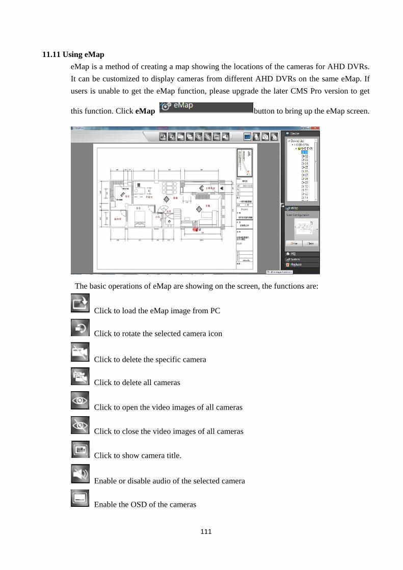
111
11.11 Using eMap
eMap is a method of creating a map showing the locations of the cameras for AHD DVRs.
It can be customized to display cameras from different AHD DVRs on the same eMap. If
users is unable to get the eMap function, please upgrade the later CMS Pro version to get
this function. Click eMap button to bring up the eMap screen.
The basic operations of eMap are showing on the screen, the functions are:
Click to load the eMap image from PC
Click to rotate the selected camera icon
Click to delete the specific camera
Click to delete all cameras
Click to open the video images of all cameras
Click to close the video images of all cameras
Click to show camera title.
Enable or disable audio of the selected camera
Enable the OSD of the cameras
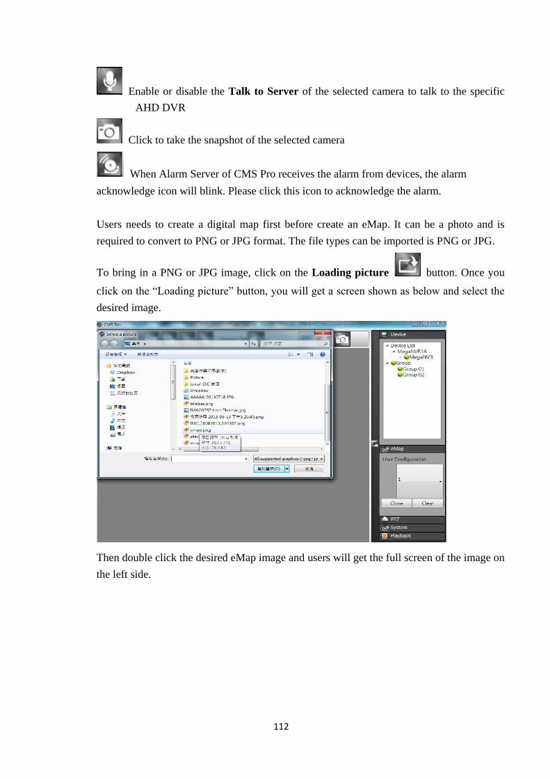
112
Enable or disable the Talk to Server of the selected camera to talk to the specific
AHD DVR
Click to take the snapshot of the selected camera
When Alarm Server of CMS Pro receives the alarm from devices, the alarm
acknowledge icon will blink. Please click this icon to acknowledge the alarm.
Users needs to create a digital map first before create an eMap. It can be a photo and is
required to convert to PNG or JPG format. The file types can be imported is PNG or JPG.
To bring in a PNG or JPG image, click on the Loading picture button. Once you
click on the “Loading picture” button, you will get a screen shown as below and select the
desired image.
Then double click the desired eMap image and users will get the full screen of the image on
the left side.
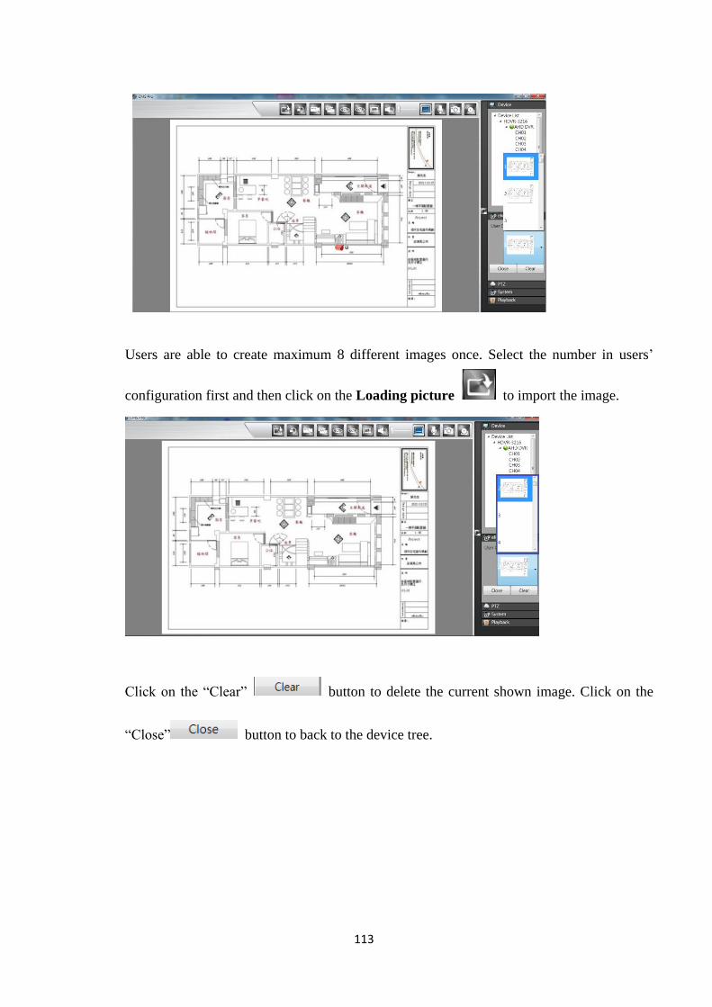
113
Users are able to create maximum 8 different images once. Select the number in users’
configuration first and then click on the Loading picture to import the image.
Click on the “Clear” button to delete the current shown image. Click on the
“Close” button to back to the device tree.
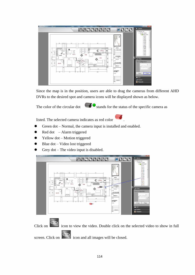
114
Since the map is in the position, users are able to drag the cameras from different AHD
DVRs to the desired spot and camera icons will be displayed shown as below.
The color of the circular dot stands for the status of the specific camera as
listed. The selected camera indicates as red color .
Green dot – Normal, the camera input is installed and enabled.
Red dot – Alarm triggered
Yellow dot – Motion triggered
Blue dot – Video lost triggered
Grey dot – The video input is disabled.
Click on icon to view the video. Double click on the selected video to show in full
screen. Click on icon and all images will be closed.
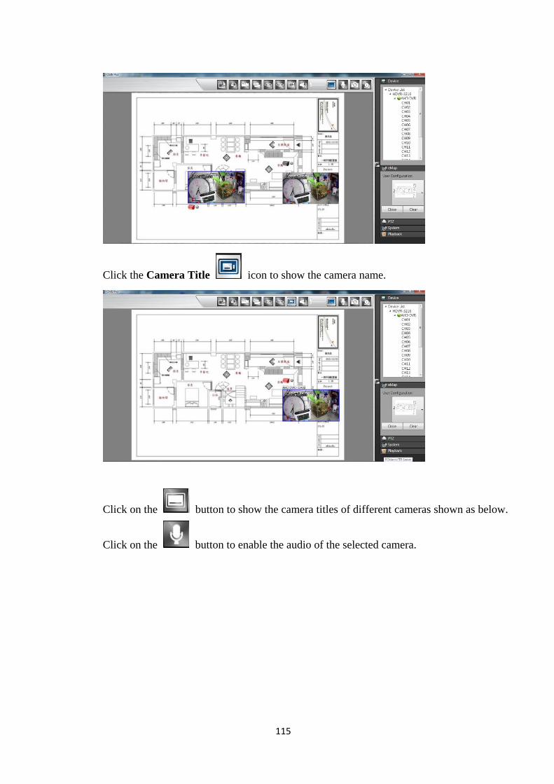
115
Click the Camera Title icon to show the camera name.
Click on the button to show the camera titles of different cameras shown as below.
Click on the button to enable the audio of the selected camera.
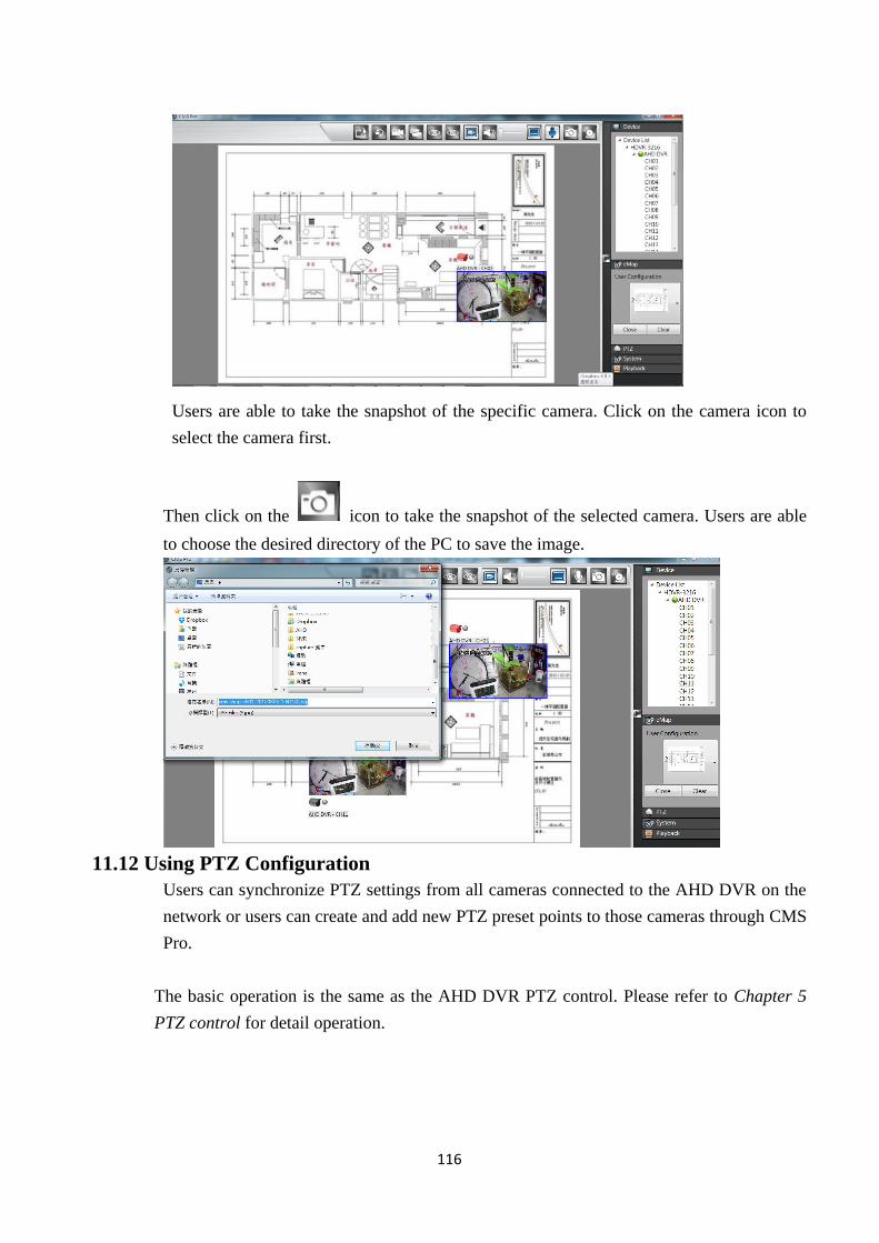
116
Users are able to take the snapshot of the specific camera. Click on the camera icon to
select the camera first.
Then click on the icon to take the snapshot of the selected camera. Users are able
to choose the desired directory of the PC to save the image.
11.12 Using PTZ Configuration
Users can synchronize PTZ settings from all cameras connected to the AHD DVR on the
network or users can create and add new PTZ preset points to those cameras through CMS
Pro.
The basic operation is the same as the AHD DVR PTZ control. Please refer to Chapter 5
PTZ control for detail operation.
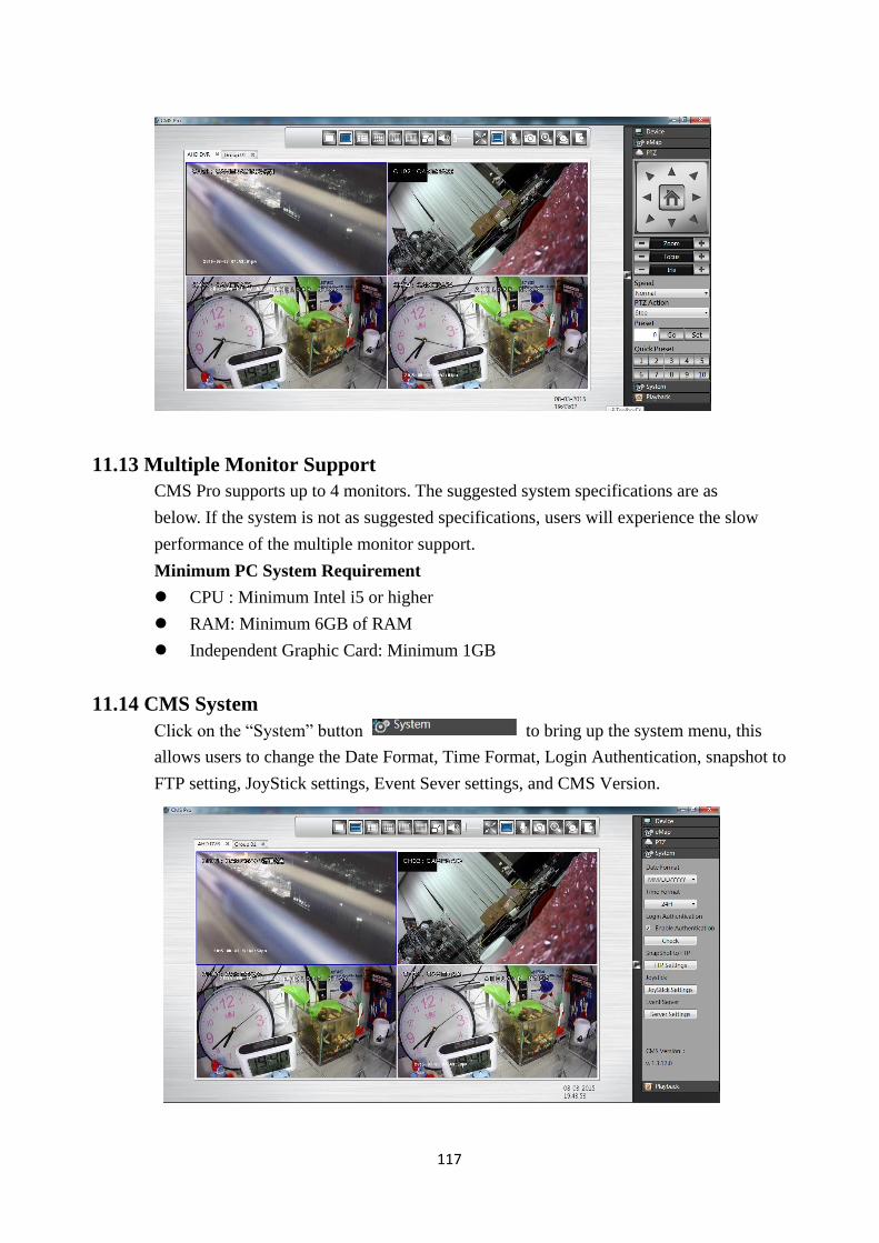
117
11.13 Multiple Monitor Support
CMS Pro supports up to 4 monitors. The suggested system specifications are as
below. If the system is not as suggested specifications, users will experience the slow
performance of the multiple monitor support.
Minimum PC System Requirement
CPU : Minimum Intel i5 or higher
RAM: Minimum 6GB of RAM
Independent Graphic Card: Minimum 1GB
11.14 CMS System
Click on the “System” button to bring up the system menu, this
allows users to change the Date Format, Time Format, Login Authentication, snapshot to
FTP setting, JoyStick settings, Event Sever settings, and CMS Version.
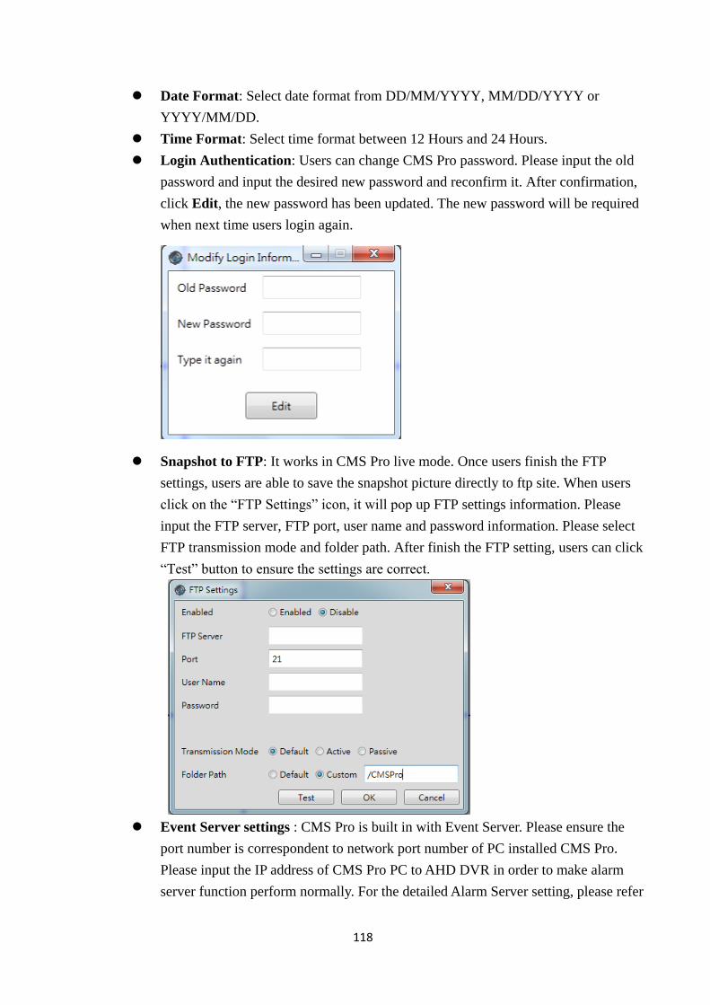
118
Date Format: Select date format from DD/MM/YYYY, MM/DD/YYYY or
YYYY/MM/DD.
Time Format: Select time format between 12 Hours and 24 Hours.
Login Authentication: Users can change CMS Pro password. Please input the old
password and input the desired new password and reconfirm it. After confirmation,
click Edit, the new password has been updated. The new password will be required
when next time users login again.
Snapshot to FTP: It works in CMS Pro live mode. Once users finish the FTP
settings, users are able to save the snapshot picture directly to ftp site. When users
click on the “FTP Settings” icon, it will pop up FTP settings information. Please
input the FTP server, FTP port, user name and password information. Please select
FTP transmission mode and folder path. After finish the FTP setting, users can click
“Test” button to ensure the settings are correct.
Event Server settings : CMS Pro is built in with Event Server. Please ensure the
port number is correspondent to network port number of PC installed CMS Pro.
Please input the IP address of CMS Pro PC to AHD DVR in order to make alarm
server function perform normally. For the detailed Alarm Server setting, please refer
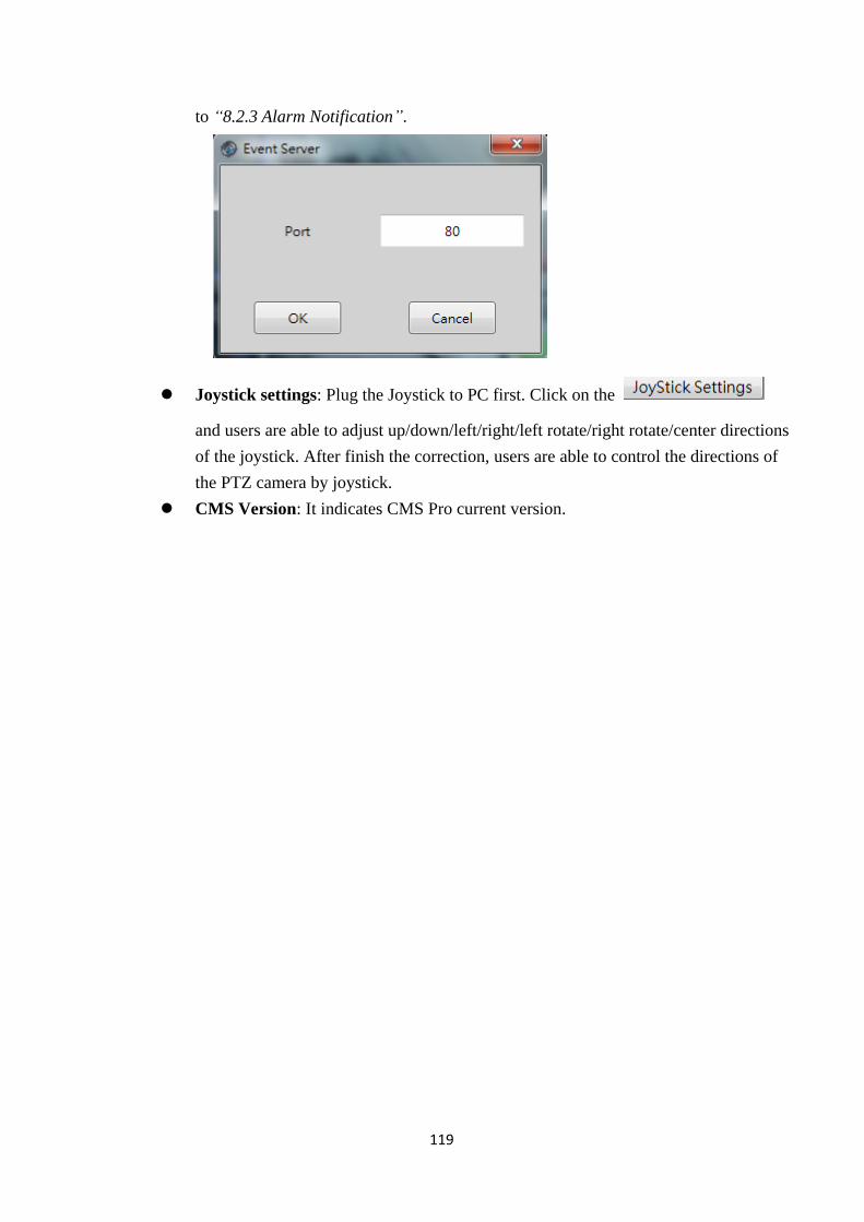
119
to “8.2.3 Alarm Notification”.
Joystick settings: Plug the Joystick to PC first. Click on the
and users are able to adjust up/down/left/right/left rotate/right rotate/center directions
of the joystick. After finish the correction, users are able to control the directions of
the PTZ camera by joystick.
CMS Version: It indicates CMS Pro current version.