Embed Size (px)
Citation preview
Uncontrolled Copy when printed or downloaded. Please refer to the 4D Systems website for the latest Revision of this document
VGA Graphics Engine - PICASO µVGA-III
Document Date: 22nd May 2013
Document Revision: 1.4 DATA
SH
EET
4D SYSTEMS TURNING TECHNOLOGY INTO ART
mic
roVG
A –
VGA G
RAPH
ICS E
NGIN
E
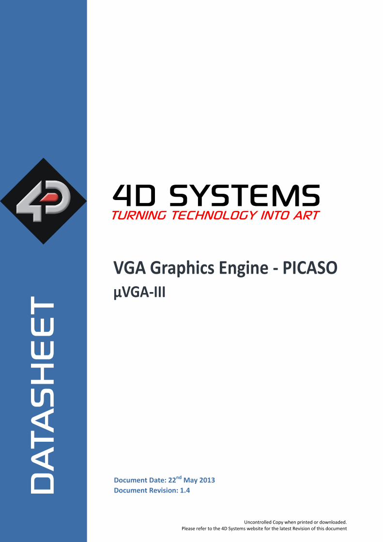
The µVGA-III is a compact and cost effective VGA Graphics Engine packed with plenty of features, ready to become the GUI for your target application, and capable of being an interface controller for a number of applications. Embedded at the heart of the design is the PICASO processor, which is driven by a highly optimised virtual core engine called EVE (Extensible Virtual Engine). An extensive range of hardware and software peripherals have been integrated into the design, to give the user freedom to adapt the module to suit almost any application.
The module combines a display driver capable of 320x240 (QVGA), 640x480 (VGA) and 800x480 (WVGA) resolution output to a standard VGA display, micro-SD card connector, along with a group of general purpose input/output pins (GPIO's), including I
2C and
serial UART communications.
This module serves as a perfect solution to connect to an external VGA monitor for an application requiring animation, slideshows, images or sound. This PICASO driven Intelligent Display Module is a perfect example of where art meets technology.
Audio support provided on the display module is supplied by the PICASO processor, outputting a line-level audio signal, ready to drive an external amplifier of choice. A simple instruction enables the user to play audio files while continuing the execution of the user application code, such as display updates, communications and much more. The micro-SD card slot provides the user with expandable memory space suitable for multimedia file retrieval, including images, animations and movie clips, as well as data logging applications.
The module can be programmed as a master or slave device using the Workshop 4 IDE Software, but can also be configured as a serial slave for use with your favourite Host Controller. Freedom is at your fingertips with the intelligent µVGA-III VGA Graphics Engine module.
Overview
mic
roLC
D P
ICASO D
ISPLA
Y
mic
roVG
A –
VGA G
RAPH
ICS E
NGIN
E
Contents
1. Description ............................................................................................................................. 4
2. Features ................................................................................................................................. 4
3. Pin Configuration and Summary .............................................................................................. 5
4. Hardware Interface - Pins........................................................................................................ 7
Serial Ports - COM0, COM1 UARTS ........................................................................................................ 7 4.1.
General Purpose I/O ............................................................................................................................... 7 4.2.
System Pins ............................................................................................................................................ 8 4.3.
VGA Output Header and Pads ................................................................................................................ 8 4.4.
5. Firmware / PmmC Programming ............................................................................................. 9
6. Module Features .................................................................................................................... 9
VGA - Interface ....................................................................................................................................... 9 6.1.
PICASO Processor ................................................................................................................................... 9 6.2.
Audio .................................................................................................................................................... 10 6.3.
SD/SDHC Memory Cards ...................................................................................................................... 10 6.4.
FAT16 ................................................................................................................................................... 10 6.5.
7. Hardware Tools .................................................................................................................... 11
4D Programming Cable/Adaptor .......................................................................................................... 11 7.1.
8. 4DGL - Software Language .................................................................................................... 11
9. 4D Systems - Workshop 4 IDE ................................................................................................ 12
Workshop 4 – Designer Environment .................................................................................................. 12 9.1.
Workshop 4 – ViSi Environment........................................................................................................... 12 9.2.
Workshop 4 – ViSi Genie Environment ................................................................................................ 13 9.3.
Workshop 4 – Serial Environment ........................................................................................................ 13 9.4.
10. Notes ................................................................................................................................. 14
11. Mechanical Details .............................................................................................................. 15
12. Schematic Diagram ............................................................................................................. 16
13. Schematic Diagram SHEET 2 ................................................................................................ 17
14. Specifications and Ratings ................................................................................................... 18
15. Legal Notice ........................................................................................................................ 19
16. Contact Information............................................................................................................ 19
4D SYSTEMS µVGA-III
© 2012 4D SYSTEMS Page 4 of 19 www.4dsystems.com.au
mic
roVG
A –
VGA G
RAPH
ICS E
NGIN
E
1. Description The μVGA-III module is a compact and cost effective standalone VGA graphics engine powered by the PICASO graphics processor. It can provide a QVGA/VGA/WVGA graphics solution to any embedded project with its powerful graphics, text, image and animation capabilities, along with countless more features built inside the module. Depending on the programming environment selected when using 4D Systems’ Workshop 4 IDE Software, the user can choose to program the μVGA-III module as a stand-alone device, or as a slave device to an external host controller. When the μVGA-III is used as a stand-alone device, it allows the user to take complete control of all available resources on that hardware platform such as the Serial Ports, uSD memory card, I/O pins, etc. This eliminates the need for an external host controller/processor to drive the μVGA-III module via serial commands. It provides the user complete control over the hardware module allowing them to quickly develop practical applications. When the μVGA-III is used as a serial slave device to an external host controller, the host sends specific commands over its serial UART to the μVGA-III to produce the desired user displays. The μVGA-III features a remote VGA connector, which is able to be disconnected from the PCB. The remote VGA connector enables flexible mounting and connection options when using the μVGA-III. A 30 way header is provided on the rear of the PCB, which is left unpopulated from the factory, however the header is provided with the module. This can be soldered by the user if required, to gain additional IO and comms if required. Wires can also be soldered directly to the PCB if desired.
2. Features
• Simple VGA interface to variety of monitors and LCD screens.
• Supports the following resolutions:
• 320 x 240 (QVGA)
• 640 x 480 (VGA)
• 800 x 480 (WVGA)
• Supports RGB 65K true to life colours.
• Easy 5 pin interface to any host device: VCC, TX, RX, GND, RESET
• Powered by the 4D-Labs PICASO processor (also available as separate OEM IC)
• 14KB of flash memory for user code storage and 14KB of SRAM for user variables, or 14KB shared user code and program variables.
• 2 x Asynchronous hardware serial UART ports (COM0, COM1), TTL interface, with 300 to 600K baud.
• 1 x I2C interface (Master).
• 8 x 16 bit timers with 1 millisecond resolution.
• 13 x General Purpose I/O pins. Supports fast 8-bit parallel data transfer through Upper 8 bits.
• On-board micro-SD memory card adaptor for multimedia storage and data logging purposes. HC memory card support is also available for cards larger than 4GB.
• DOS compatible file access (FAT16 format) as well as low level access to card memory.
• Dedicated Line-Level PWM Audio pin driven by WAV files from micro-SD card.
• Built in extensive 4DGL graphics and system library functions.
• Display full colour images, animations, icons and video clips.
• Supports all available Windows fonts.
• A 30 pin header for I/O expansion (supplied but not soldered onto the PCB)
• 15 pin D-type standard VGA connector to interface to any external VGA monitor, on a remote and detachable cable.
• 4.0V to 5.5V range operation (single supply).
• Module dimensions: 39.0 x 63.0 x 21.5mm
• Weight ~ 17g.
• RoHS Compliant.
4D SYSTEMS µVGA-III
© 2012 4D SYSTEMS Page 5 of 19 www.4dsystems.com.au
mic
roVG
A –
VGA G
RAPH
ICS E
NGIN
E
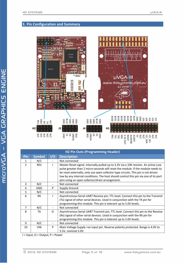
3. Pin Configuration and Summary
H2 J3 J4 H1
H2 Pin Outs (Programming Header)
Pin Symbol I/O Description 1 N/C - Not connected
2 RES I Master Reset signal. Internally pulled up to 3.3V via a 10K resistor. An active Low pulse greater than 2 micro-seconds will reset the module. If the module needs to be reset externally, only use open collector type circuits. This pin is not driven low by any internal conditions. The host should control this pin via one of its port pins using an open collector/drain arrangement.
3 N/C - Not connected
4 GND P Supply Ground
5 N/C - Not connected
6 RX I Asynchronous Serial UART Receive pin, TTL level. Connect this pin to the Transmit (Tx) signal of other serial devices. Used in conjunction with the TX pin for programming this module. This pin is tolerant up to 5.0V levels.
7 N/C - Not connected
8 TX O Asynchronous Serial UART Transmit pin, TTL level. Connect this pin to the Receive (Rx) signal of other serial devices. Used in conjunction with the RX pin for programming this module. This pin is tolerant up to 5.0V levels.
9 N/C - Not connected
10 VIN P Main Voltage Supply +ve input pin. Reverse polarity protected. Range is 4.0V to 5.5V, nominal 5.0V.
I = Input, O = Output, P = Power
IO1
IO2
IO
3
IO4
IO
5
GN
D
GN
D
BU
S7
BU
S6 B
US5
BU
S4 B
US3
BU
S2 B
US1
BU
S0
N/C
N/C
I2
C_SC
L
I2C
_SDA
N
/C
N/C
5
V
AU
DIO
A
UD
ENB
RESET
3.3
V O
UT
RX
0
TX0
TX1
RX
1
+5V
TX
RX
GN
D
RES
N/C
N
/C
N/C
N
/C
N/C
GN
D
GN
D
GN
D
BLU
E G
ND
RED
G
REEN
HS
VS
GN
D
GN
D
BLU
E G
ND
GN
D
GN
D
GN
D
VS
HS
GR
EEN
RED
4D SYSTEMS µVGA-III
© 2012 4D SYSTEMS Page 6 of 19 www.4dsystems.com.au
mic
roVG
A –
VGA G
RAPH
ICS E
NGIN
E
I = Input, O = Output, P = Power
J3 and J4 Pin Outs (VGA Headers)
Pin Symbol I/O Description 1 GND P Ground
2 GND P Ground
3 VS O Vertical Sync
4 BLUE O Blue (RGB)
5 HS O Horizontal Sync
6 GND P Ground
7 GREEN O Green (RGB)
8 GND P Ground
9 RED O Red (RGB)
10 GND P Ground (STRIPED WIRE ON THE VGA CABLE, FOR J3 ONLY – See Section 4.4)
I = Input, O = Output, P = Power
H1 Pin Outs (I/O Expansion Header)
Pin Symbol I/O Description 1 IO1 I/O General Purpose Input Output 1 Pin
2 N/C - Not connected
3 IO2 I/O General Purpose Input Output 2 Pin
4 N/C - Not connected
5 IO3 I/O General Purpose Input Output 3 Pin
6 SCL O I2C Clock Output
7 IO4 I/O General Purpose Input Output 4 Pin
8 SDA I/O I2C Bidirectional Data
9 IO5 I/O General Purpose Input Output 5 Pin
10 N/C - Not connected
11 GND P Supply Ground
12 N/C - Not connected
13 GND P Supply Ground
14 +5V P Supply Input +ve, 4.0V to 5.5V, 5.0V Nominal
15 BUS7 I/O IO Bus (BUS0..7) bit 7
16 AUDIO O Audio Output, TTL Line level for connecting to an external amplifier
17 BUS6 I/O IO Bus (BUS0..7) bit 6
18 AUDENB O Audio Enable Output, to enable an external Amplifier (if required)
19 BUS5 I/O IO Bus (BUS0..7) bit 5
20 RES I Master Reset, Active Low (GND) (Refer H2 Pinout)
21 BUS4 I/O IO Bus (BUS0..7) bit 4
22 3.3V OUT P 3.3V Output, 20mA Max supply
23 BUS3 I/O IO Bus (BUS0..7) bit 3
24 RX0 I Asynchronous serial port 0 receive pin. COM0 (same as the RX pin on the H2 Programming Header)
25 BUS2 I/O IO Bus (BUS0..7) bit 2
26 TX0 O Asynchronous serial port 0 transmit pin. COM0 (same as the TX pin on the H2 Programming Header)
27 BUS1 I/O IO Bus (BUS0..7) bit 1
28 TX1 O Asynchronous serial port 1 transmit pin. COM1
29 BUS0 I/O IO Bus (BUS0..7) bit 0
30 RX1 I Asynchronous serial port 1 receive pin. COM1
4D SYSTEMS µVGA-III
© 2012 4D SYSTEMS Page 7 of 19 www.4dsystems.com.au
mic
roVG
A –
VGA G
RAPH
ICS E
NGIN
E
4. Hardware Interface - Pins The μVGA-III provides both a hardware and software interface. This section describes in detail the hardware interface pins of the device.
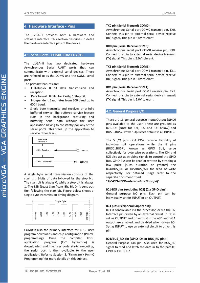
Serial Ports - COM0, COM1 UARTS 4.1. The μVGA-III has two dedicated hardware Asynchronous Serial UART ports that can communicate with external serial devices. These are referred to as the COM0 and the COM1 serial ports. The primary features are: • Full-Duplex 8 bit data transmission and
reception. • Data format: 8 bits, No Parity, 1 Stop bit. • Independent Baud rates from 300 baud up to
600K baud. • Single byte transmits and receives or a fully
buffered service. The buffered service feature runs in the background capturing and buffering serial data without the user application having to constantly poll any of the serial ports. This frees up the application to service other tasks.
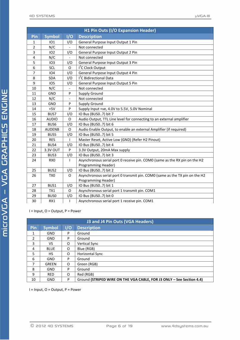
A single byte serial transmission consists of the start bit, 8-bits of data followed by the stop bit. The start bit is always 0, while a stop bit is always 1. The LSB (Least Significant Bit, Bit 0) is sent out first following the start bit. Figure below shows a single byte transmission timing diagram.
COM0 is also the primary interface for 4DGL user program downloads and chip configuration (PmmC programming). Once the compiled 4DGL application program (EVE byte-code) is downloaded and the user code starts executing, the serial port is then available to the user application. Refer to Section 5. ‘Firmware / PmmC Programming’ for more details on this subject.
TX0 pin (Serial Transmit COM0): Asynchronous Serial port COM0 transmit pin, TX0. Connect this pin to external serial device receive (Rx) signal. This pin is 5.0V tolerant. RX0 pin (Serial Receive COM0): Asynchronous Serial port COM0 receive pin, RX0. Connect this pin to external serial device transmit (Tx) signal. This pin is 5.0V tolerant. TX1 pin (Serial Transmit COM1): Asynchronous Serial port COM1 transmit pin, TX1. Connect this pin to external serial device receive (Rx) signal. This pin is 5.0V tolerant. RX1 pin (Serial Receive COM1): Asynchronous Serial port COM1 receive pin, RX1. Connect this pin to external serial device transmit (Tx) signal. This pin is 5.0V tolerant.
General Purpose I/O 4.2. There are 13 general purpose Input/Output (GPIO) pins available to the user. These are grouped as IO1..IO5 (Note for IO1, IO2 and IO3 below) and BUS0..BUS7. Power-Up Reset default is all INPUTS. The 5 I/O pins (IO1..IO5), provide flexibility of individual bit operations while the 8 pins (BUS0..BUS7), known as GPIO BUS, serve collectively for byte wise operations. The IO4 and IO5 also act as strobing signals to control the GPIO Bus. GPIO Bus can be read or written by strobing a low pulse (50ns duration or greater) the IO4/BUS_RD or IO5/BUS_WR for read or write respectively. For detailed usage refer to the separate document titled: “PICASO-4DGL-Internal-Functions.pdf” IO1-IO5 pins (excluding IO3) (2 x GPIO pins): General purpose I/O pins. Each pin can be individually set for INPUT or an OUTPUT. IO3 pins (Peripheral Supply pin): IO3 is controllable via the processor, or via the H2 Interface pin driven by an external circuit. If IO3 is set as OUTPUT and driven HIGH the uSD and VGA output are enabled, and disabled when driven LO. Set as INPUT to use an external circuit to drive this pin. IO4/BUS_RD pin (GPIO IO4 or BUS_RD pin): General Purpose IO4 pin. Also used for BUS_RD signal to read and latch the data in to the parallel GPIO BUS0..BUS7.

4D SYSTEMS µVGA-III
© 2012 4D SYSTEMS Page 8 of 19 www.4dsystems.com.au
mic
roVG
A –
VGA G
RAPH
ICS E
NGIN
E
IO5/BUS_WR pin (GPIO IO5 or BUS_WR pin): General Purpose IO5 pin. Also used for BUS_WR signal to write and latch the data to the parallel GPIO BUS0..BUS7. BUS0-BUS7 pins (GPIO 8-Bit Bus): 8-bit parallel General purpose I/O Bus.
Note: All GPIO pins are 5.0V tolerant.
System Pins 4.3. +5V (Module Voltage Input) H1 pin 14, H2 pin 10: Module supply voltage input pin. This pin must be connected to a regulated supply voltage in the range of 4.0 Volts to 5.5 Volts DC. Nominal operating voltage is 5.0 Volts. 3.3V Out (3.3V Regulated Output) H1 pin 22: External circuitry that requires a regulated 3.3V supply can be powered up via this pin. Maximum available current is 20mA. GND (Module Ground) H1 pin 11/13, H2 pin 4: Device ground pins. These pins must be connected to ground. RESET (Module Master Reset) H1 pin 20, H2 pin 2: Module Master Reset pin. An active low pulse of greater than 2μs will reset the module. Internally pulled up to 3.3V via a 10K resistor. Only use open collector type circuits to reset the device if an external reset is required. AUDENB (Audio Enable Output) H1 pin 18: Output dedicated to enable or disable an external audio amplifier (if required). AUDIO (Audio Line Level Output) H1 pin 16: Line Level output specifically for Audio. This pin is for connecting to an external amplifier. When used in conjunction with AUDENB this pin can be used as a line-level output (AUDENB enabled is LOW) to drive an external amplifier.
VGA Output Header and Pads 4.4. The μVGA-III features a remote VGA connector, which is able to be disconnected from the PCB. The remote VGA connector enables flexible mounting and connection options when using the μVGA-III. Note: The orientation of the VGA cable onto the PCB is important. The striped wire on the VGA cable indicates Pin 10 on Header J3. Extra Video Out pads are provided on the rear of the PCB (J4), for added flexibility and wiring options. Note: The extra Video Out pads (J4) are a mirror image to the header on the front of the PCB (J3), so the supplied VGA cable cannot simply be plugged in if a header is attached.
4D SYSTEMS µVGA-III
© 2012 4D SYSTEMS Page 9 of 19 www.4dsystems.com.au
mic
roVG
A –
VGA G
RAPH
ICS E
NGIN
E
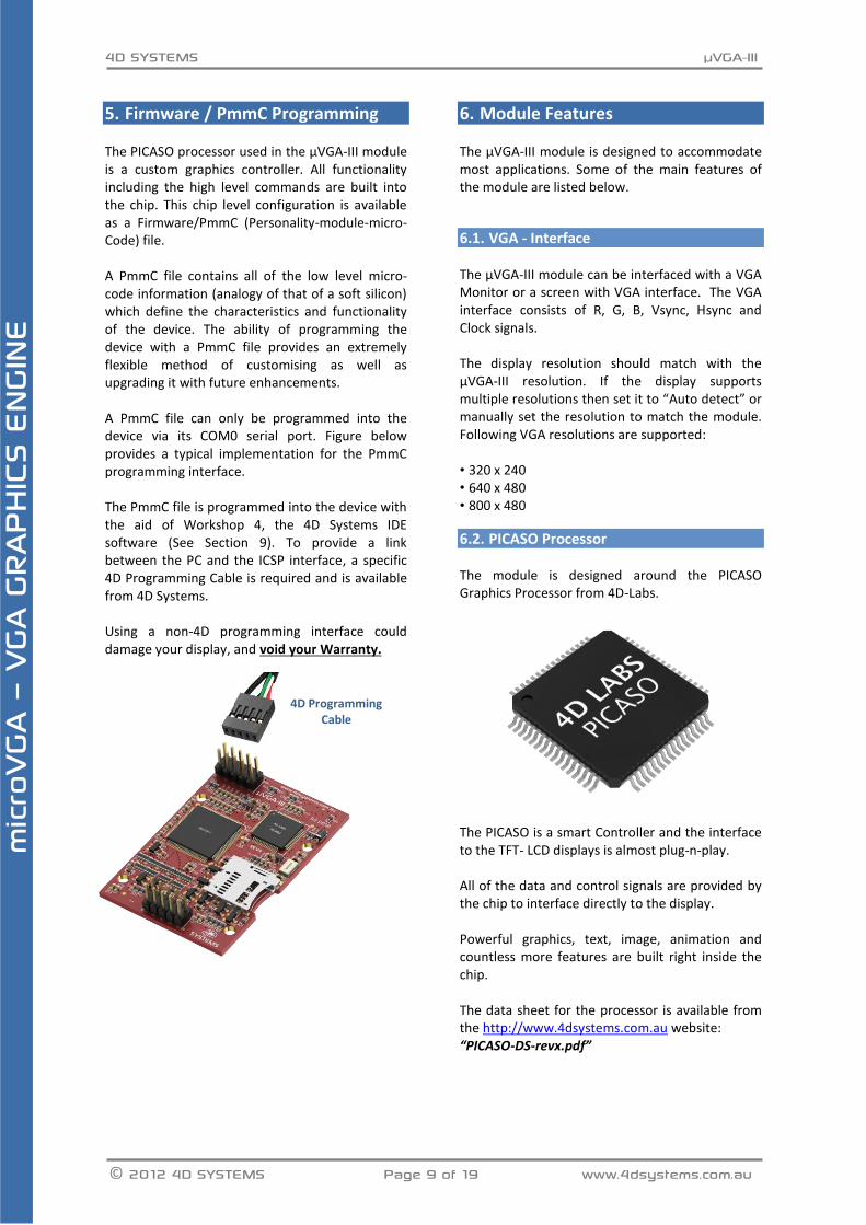
5. Firmware / PmmC Programming The PICASO processor used in the μVGA-III module is a custom graphics controller. All functionality including the high level commands are built into the chip. This chip level configuration is available as a Firmware/PmmC (Personality-module-micro-Code) file. A PmmC file contains all of the low level micro-code information (analogy of that of a soft silicon) which define the characteristics and functionality of the device. The ability of programming the device with a PmmC file provides an extremely flexible method of customising as well as upgrading it with future enhancements. A PmmC file can only be programmed into the device via its COM0 serial port. Figure below provides a typical implementation for the PmmC programming interface. The PmmC file is programmed into the device with the aid of Workshop 4, the 4D Systems IDE software (See Section 9). To provide a link between the PC and the ICSP interface, a specific 4D Programming Cable is required and is available from 4D Systems. Using a non-4D programming interface could damage your display, and void your Warranty.
6. Module Features The μVGA-III module is designed to accommodate most applications. Some of the main features of the module are listed below.
VGA - Interface 6.1. The μVGA-III module can be interfaced with a VGA Monitor or a screen with VGA interface. The VGA interface consists of R, G, B, Vsync, Hsync and Clock signals. The display resolution should match with the μVGA-III resolution. If the display supports multiple resolutions then set it to “Auto detect” or manually set the resolution to match the module. Following VGA resolutions are supported: • 320 x 240 • 640 x 480 • 800 x 480
PICASO Processor 6.2. The module is designed around the PICASO Graphics Processor from 4D-Labs.
The PICASO is a smart Controller and the interface to the TFT- LCD displays is almost plug-n-play. All of the data and control signals are provided by the chip to interface directly to the display. Powerful graphics, text, image, animation and countless more features are built right inside the chip. The data sheet for the processor is available from the http://www.4dsystems.com.au website: “PICASO-DS-revx.pdf”
4D Programming Cable
4D SYSTEMS µVGA-III
© 2012 4D SYSTEMS Page 10 of 19 www.4dsystems.com.au
mic
roVG
A –
VGA G
RAPH
ICS E
NGIN
E
Audio 6.3.
Audio playback support in the PICASO Processor enables the μVGA-III module to play WAV audio at Line Levels to a pin on the expansion header. A simple instruction enables the user to play/pause/stop audio files while continuing the execution of the users code, such as display updates, touch recognition, communications, etc. The audio system also allows real time pitch change of audio samples. For a complete list of audio commands please refer to the separate document titled: “PICASO-4DGL-Internal-Functions.pdf”
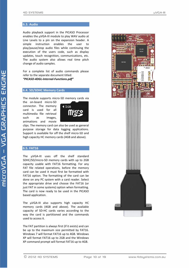
SD/SDHC Memory Cards 6.4. The module supports micro-SD memory cards via the on-board micro-SD connector. The memory card is used for all multimedia file retrieval such as images, animations and movie clips. The memory card can also be used as general purpose storage for data logging applications. Support is available for off the shelf micro-SD and high capacity HC memory cards (4GB and above).
FAT16 6.5. The μVGA-III uses off the shelf standard SDHC/SD/micro-SD memory cards with up to 2GB capacity usable with FAT16 formatting. For any FAT file related operations, before the memory card can be used it must first be formatted with FAT16 option. The formatting of the card can be done on any PC system with a card reader. Select the appropriate drive and choose the FAT16 (or just FAT in some systems) option when formatting. The card is now ready to be used in the PICASO based application. The μVGA-III also supports high capacity HC memory cards (4GB and above). The available capacity of SD-HC cards varies according to the way the card is partitioned and the commands used to access it. The FAT partition is always first (if it exists) and can be up to the maximum size permitted by FAT16. Windows 7 will format FAT16 up to 4GB. Windows XP will format FAT16 up to 2GB and the Windows XP command prompt will format FAT16 up to 4GB.
4D SYSTEMS µVGA-III
© 2012 4D SYSTEMS Page 11 of 19 www.4dsystems.com.au
mic
roVG
A –
VGA G
RAPH
ICS E
NGIN
E
7. Hardware Tools The following hardware tools are required for full control of the μVGA-III module.
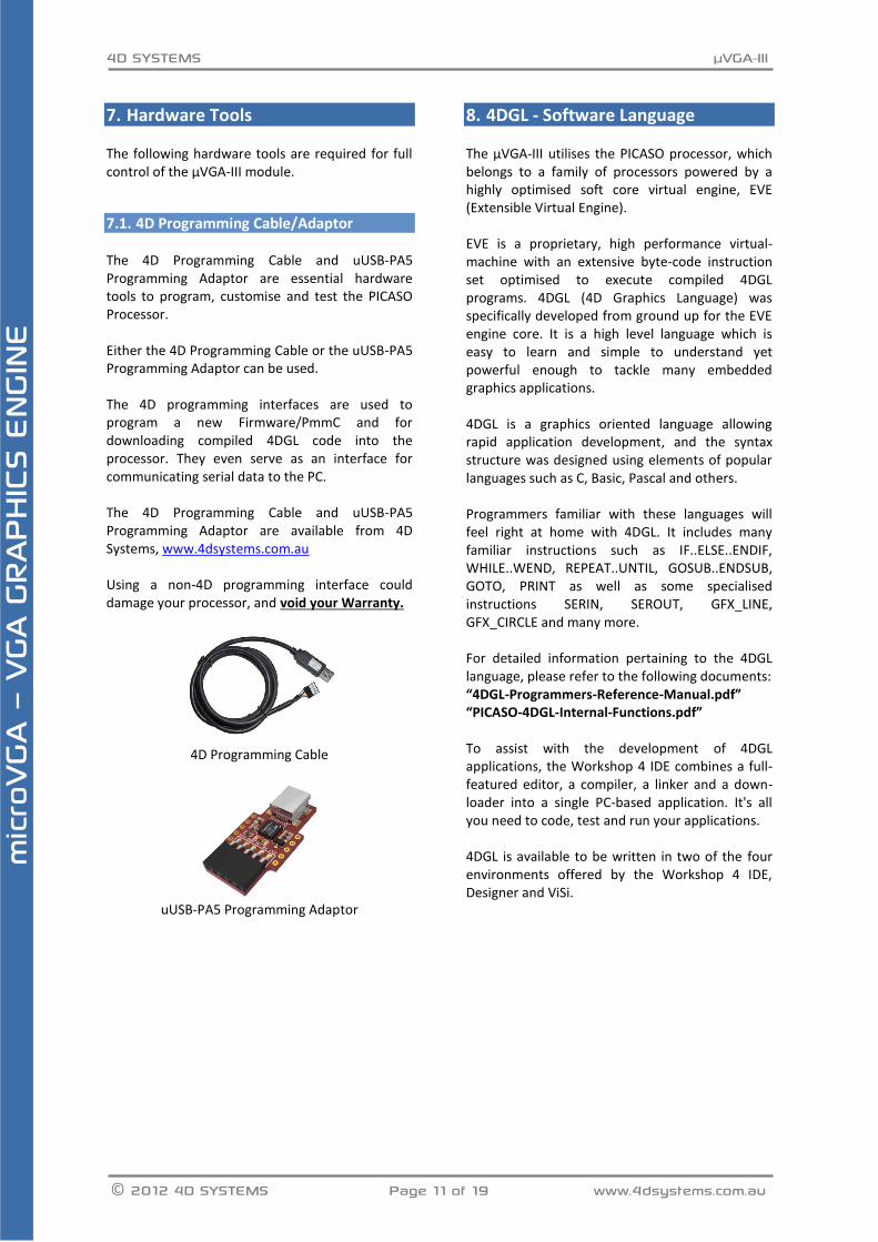
4D Programming Cable/Adaptor 7.1. The 4D Programming Cable and uUSB-PA5 Programming Adaptor are essential hardware tools to program, customise and test the PICASO Processor. Either the 4D Programming Cable or the uUSB-PA5 Programming Adaptor can be used. The 4D programming interfaces are used to program a new Firmware/PmmC and for downloading compiled 4DGL code into the processor. They even serve as an interface for communicating serial data to the PC. The 4D Programming Cable and uUSB-PA5 Programming Adaptor are available from 4D Systems, www.4dsystems.com.au Using a non-4D programming interface could damage your processor, and void your Warranty.
4D Programming Cable
uUSB-PA5 Programming Adaptor
8. 4DGL - Software Language The μVGA-III utilises the PICASO processor, which belongs to a family of processors powered by a highly optimised soft core virtual engine, EVE (Extensible Virtual Engine). EVE is a proprietary, high performance virtual-machine with an extensive byte-code instruction set optimised to execute compiled 4DGL programs. 4DGL (4D Graphics Language) was specifically developed from ground up for the EVE engine core. It is a high level language which is easy to learn and simple to understand yet powerful enough to tackle many embedded graphics applications. 4DGL is a graphics oriented language allowing rapid application development, and the syntax structure was designed using elements of popular languages such as C, Basic, Pascal and others. Programmers familiar with these languages will feel right at home with 4DGL. It includes many familiar instructions such as IF..ELSE..ENDIF, WHILE..WEND, REPEAT..UNTIL, GOSUB..ENDSUB, GOTO, PRINT as well as some specialised instructions SERIN, SEROUT, GFX_LINE, GFX_CIRCLE and many more. For detailed information pertaining to the 4DGL language, please refer to the following documents: “4DGL-Programmers-Reference-Manual.pdf” “PICASO-4DGL-Internal-Functions.pdf” To assist with the development of 4DGL applications, the Workshop 4 IDE combines a full-featured editor, a compiler, a linker and a down-loader into a single PC-based application. It's all you need to code, test and run your applications. 4DGL is available to be written in two of the four environments offered by the Workshop 4 IDE, Designer and ViSi.
4D SYSTEMS µVGA-III
© 2012 4D SYSTEMS Page 12 of 19 www.4dsystems.com.au
mic
roVG
A –
VGA G
RAPH
ICS E
NGIN
E
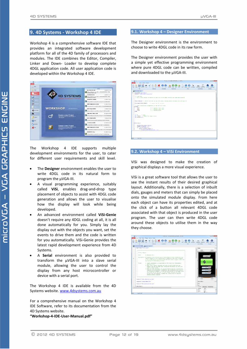
9. 4D Systems - Workshop 4 IDE Workshop 4 is a comprehensive software IDE that provides an integrated software development platform for all of the 4D family of processors and modules. The IDE combines the Editor, Compiler, Linker and Down- Loader to develop complete 4DGL application code. All user application code is developed within the Workshop 4 IDE.
The Workshop 4 IDE supports multiple development environments for the user, to cater for different user requirements and skill level.
The Designer environment enables the user to write 4DGL code in its natural form to program the μVGA-III.
A visual programming experience, suitably called ViSi, enables drag-and-drop type placement of objects to assist with 4DGL code generation and allows the user to visualise how the display will look while being developed.
An advanced environment called ViSi-Genie doesn’t require any 4DGL coding at all, it is all done automatically for you. Simply lay the display out with the objects you want, set the events to drive them and the code is written for you automatically. ViSi-Genie provides the latest rapid development experience from 4D Systems.
A Serial environment is also provided to transform the μVGA-III into a slave serial module, allowing the user to control the display from any host microcontroller or device with a serial port.
The Workshop 4 IDE is available from the 4D Systems website. www.4dsystems.com.au For a comprehensive manual on the Workshop 4 IDE Software, refer to its documentation from the 4D Systems website. “Workshop-4-IDE-User-Manual.pdf”
Workshop 4 – Designer Environment 9.1. The Designer environment is the environment to choose to write 4DGL code in its raw form. The Designer environment provides the user with a simple yet effective programming environment where pure 4DGL code can be written, compiled and downloaded to the μVGA-III.
Workshop 4 – ViSi Environment 9.2. ViSi was designed to make the creation of graphical displays a more visual experience. ViSi is a great software tool that allows the user to see the instant results of their desired graphical layout. Additionally, there is a selection of inbuilt dials, gauges and meters that can simply be placed onto the simulated module display. From here each object can have its properties edited, and at the click of a button all relevant 4DGL code associated with that object is produced in the user program. The user can then write 4DGL code around these objects to utilise them in the way they choose.
4D SYSTEMS µVGA-III
© 2012 4D SYSTEMS Page 13 of 19 www.4dsystems.com.au
mic
roVG
A –
VGA G
RAPH
ICS E
NGIN
E
Workshop 4 – ViSi Genie Environment 9.3.
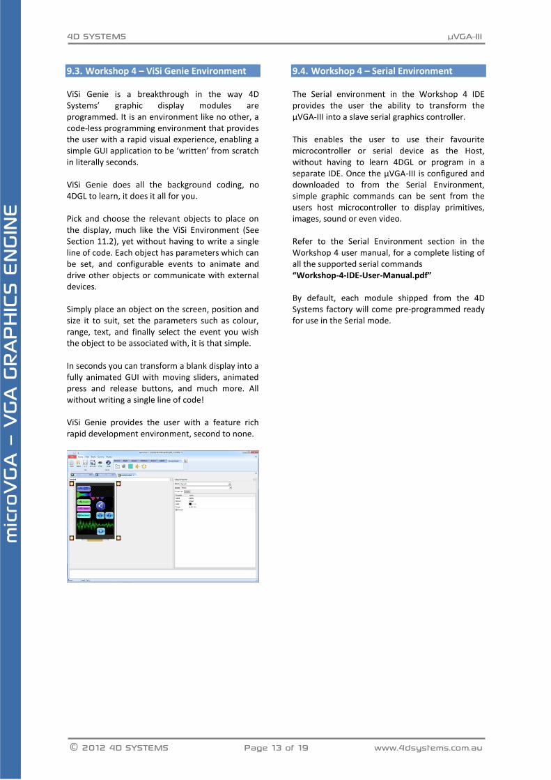
ViSi Genie is a breakthrough in the way 4D Systems’ graphic display modules are programmed. It is an environment like no other, a code-less programming environment that provides the user with a rapid visual experience, enabling a simple GUI application to be ‘written’ from scratch in literally seconds. ViSi Genie does all the background coding, no 4DGL to learn, it does it all for you. Pick and choose the relevant objects to place on the display, much like the ViSi Environment (See Section 11.2), yet without having to write a single line of code. Each object has parameters which can be set, and configurable events to animate and drive other objects or communicate with external devices. Simply place an object on the screen, position and size it to suit, set the parameters such as colour, range, text, and finally select the event you wish the object to be associated with, it is that simple. In seconds you can transform a blank display into a fully animated GUI with moving sliders, animated press and release buttons, and much more. All without writing a single line of code! ViSi Genie provides the user with a feature rich rapid development environment, second to none.
Workshop 4 – Serial Environment 9.4. The Serial environment in the Workshop 4 IDE provides the user the ability to transform the μVGA-III into a slave serial graphics controller. This enables the user to use their favourite microcontroller or serial device as the Host, without having to learn 4DGL or program in a separate IDE. Once the μVGA-III is configured and downloaded to from the Serial Environment, simple graphic commands can be sent from the users host microcontroller to display primitives, images, sound or even video. Refer to the Serial Environment section in the Workshop 4 user manual, for a complete listing of all the supported serial commands “Workshop-4-IDE-User-Manual.pdf” By default, each module shipped from the 4D Systems factory will come pre-programmed ready for use in the Serial mode.
4D SYSTEMS µVGA-III
© 2012 4D SYSTEMS Page 14 of 19 www.4dsystems.com.au
mic
roVG
A –
VGA G
RAPH
ICS E
NGIN
E
10. Notes ________________________________________________________________________________________________________________________________________________________________________________________________________________________________________________________________________________________________________________________________________________________________________ ________________________________________________________________________________________________________________________________________________________________________________________________________________________________________________________________________________________________________________________________________________________________________ ________________________________________________________________________________________________________________________________________________________________________________________________________________________________________________________________________________________________________________________________________________________________________ ________________________________________________________________________________________________________________________________________________________________________________________________________________________________________________________________________________________________________________________________________________________________________ ________________________________________________________________________________________________________________________________________________________________________________________________________________________________________________________________________________________________________________________________________________________________________ ________________________________________________________________________________________________________________________________________________________________________________________________________________________________________________________________________________________________________________________________________________________________________ ________________________________________________________________________________________________________________________________________________________________________________________________________________________________________________________________________________________________________________________________________________________________________ ________________________________________________________________________________________________________________________________________________________________________________________________________________________________________________________________________________________________________________________________________________________________________ ________________________________________________________________________________________________________________________________________________________________________________________________________________________________________________________________________________________________________________________________________________________________________ ________________________________________________________________________________________________________________________________________________________________________________________________________________________________________________________________________________________________________________________________________________________________________ ________________________________________________________________________________________________________________________________________________________________________________________________________________________________________________________________________________________________________________________________________________________________________ ________________________________________________________________________________________________________________________________________________________________________________________________________________________________________________________________________________________________________________________________________________________________________ ________________________________________________________________________________________________________________________________________________________________________________________________________________________________________________________________________________________________________________________________________________________________________ ______________________________________________________________________________________________________________________________________________________________________________________________________________________________________________________________________________
4D SYSTEMS µVGA-III
© 2012 4D SYSTEMS Page 15 of 19 www.4dsystems.com.au
mic
roVG
A –
VGA G
RAPH
ICS E
NGIN
E
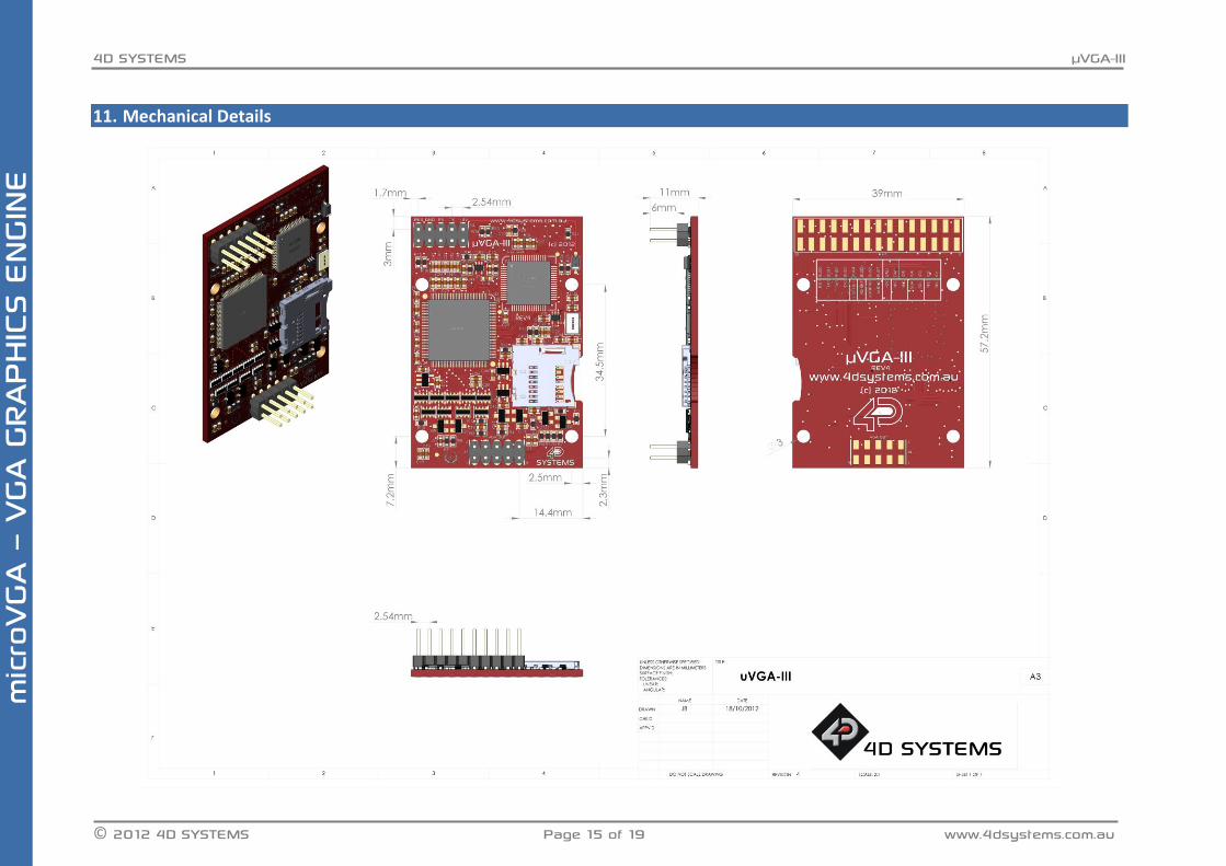
11. Mechanical Details
4D SYSTEMS µVGA-III
© 2012 4D SYSTEMS Page 16 of 19 www.4dsystems.com.au
mic
roVG
A –
VGA G
RAPH
ICS E
NGIN
E
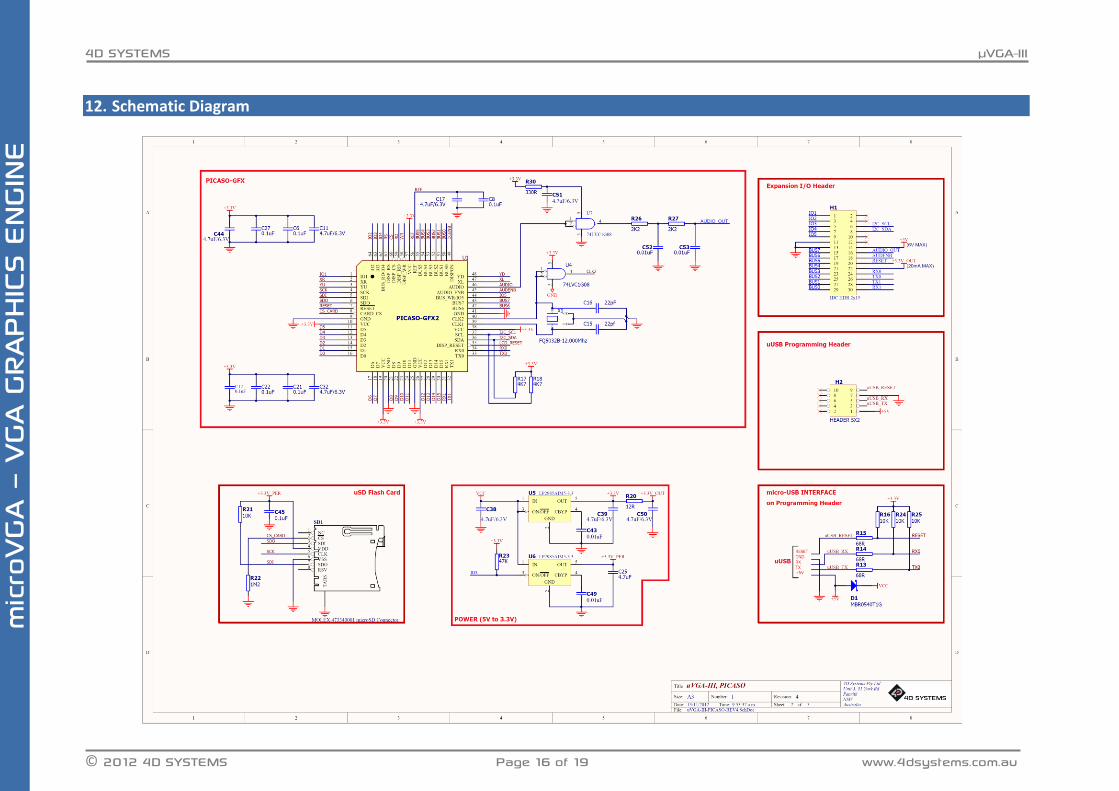
12. Schematic Diagram
4D SYSTEMS µVGA-III
© 2012 4D SYSTEMS Page 17 of 19 www.4dsystems.com.au
mic
roVG
A –
VGA G
RAPH
ICS E
NGIN
E
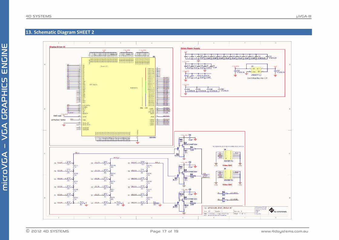
13. Schematic Diagram SHEET 2
4D SYSTEMS µVGA-III
© 2012 4D SYSTEMS Page 18 of 19 www.4dsystems.com.au
mic
roVG
A –
VGA G
RAPH
ICS E
NGIN
E
14. Specifications and Ratings
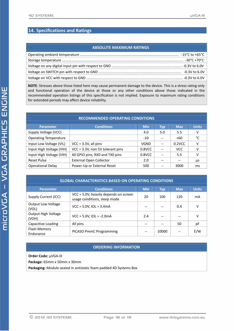
ABSOLUTE MAXIMUM RATINGS
Operating ambient temperature ................................................................................................... -15°C to +65°C
Storage temperature .......................................................................................................................... -30°C +70°C
Voltage on any digital input pin with respect to GND ....................................................................... -0.3V to 6.0V
Voltage on SWITCH pin with respect to GND ................................................................................... -0.3V to 6.0V
Voltage on VCC with respect to GND ................................................................................................. -0.3V to 6.0V
NOTE: Stresses above those listed here may cause permanent damage to the device. This is a stress rating only and functional operation of the device at those or any other conditions above those indicated in the recommended operation listings of this specification is not implied. Exposure to maximum rating conditions for extended periods may affect device reliability.
RECOMMENDED OPERATING CONDITIONS
Parameter Conditions Min Typ Max Units
Supply Voltage (VCC) 4.0 5.0 5.5 V
Operating Temperature -10 -- +60 °C
Input Low Voltage (VIL) VCC = 3.3V, all pins VGND -- 0.2VCC V
Input High Voltage (VIH) VCC = 3.3V, non 5V tolerant pins 0.8VCC -- VCC V
Input High Voltage (VIH) All GPIO pins, RX0 and TX0 pins 0.8VCC -- 5.5 V
Reset Pulse External Open Collector 2.0 -- -- µs
Operational Delay Power-Up or External Reset 500 -- 3000 ms
GLOBAL CHARACTERISTICS BASED ON OPERATING CONDITIONS
Parameter Conditions Min Typ Max Units
Supply Current (ICC) VCC = 5.0V, heavily depends on screen usage conditions, sleep mode
20 100 120 mA
Output Low Voltage (VOL)
VCC = 5.0V, IOL = 3.4mA -- -- 0.4 V
Output High Voltage (VOH)
VCC = 5.0V, IOL = -2.0mA 2.4 -- -- V
Capacitive Loading All pins -- -- 50 pF
Flash Memory Endurance
PICASO PmmC Programming -- 10000 -- E/W
ORDERING INFORMATION
Order Code: μVGA-III
Package: 65mm x 50mm x 30mm
Packaging: Module sealed in antistatic foam padded 4D Systems Box
4D SYSTEMS µVGA-III
© 2012 4D SYSTEMS Page 19 of 19 www.4dsystems.com.au
mic
roVG
A –
VGA G
RAPH
ICS E
NGIN
E
15. Legal Notice Proprietary Information The information contained in this document is the property of 4D Systems Pty. Ltd. and may be the subject of patents pending or granted, and must not be copied or disclosed without prior written permission. 4D Systems endeavours to ensure that the information in this document is correct and fairly stated but does not accept liability for any error or omission. The development of 4D Systems products and services is continuous and published information may not be up to date. It is important to check the current position with 4D Systems. 4D Systems reserves the right to modify, update or makes changes to Specifications or written material without prior notice at any time. All trademarks belong to their respective owners and are recognised and acknowledged. Disclaimer of Warranties & Limitation of Liability 4D Systems makes no warranty, either expressed or implied with respect to any product, and specifically disclaims all other warranties, including, without limitation, warranties for merchantability, non-infringement and fitness for any particular purpose. Information contained in this publication regarding device applications and the like is provided only for your convenience and may be superseded by updates. It is your responsibility to ensure that your application meets with your specifications. Images and graphics used throughout this document are for illustrative purposes only. All images and graphics used are possible to be displayed on the 4D Systems range of products, however the quality may vary. In no event shall 4D Systems be liable to the buyer or to any third party for any indirect, incidental, special, consequential, punitive or exemplary damages (including without limitation lost profits, lost savings, or loss of business opportunity) arising out of or relating to any product or service provided or to be provided by 4D Systems, or the use or inability to use the same, even if 4D Systems has been advised of the possibility of such damages. 4D Systems products are not fault tolerant nor designed, manufactured or intended for use or resale as on line control equipment in hazardous environments requiring fail – safe performance, such as in the operation of nuclear facilities, aircraft navigation or communication systems, air traffic control, direct life support machines or weapons systems in which the failure of the product could lead directly to death, personal injury or severe physical or environmental damage (‘High Risk Activities’). 4D Systems and its suppliers specifically disclaim any expressed or implied warranty of fitness for High Risk Activities. Use of 4D Systems’ products and devices in 'High Risk Activities' and in any other application is entirely at the buyer’s risk, and the buyer agrees to defend, indemnify and hold harmless 4D Systems from any and all damages, claims, suits, or expenses resulting from such use. No licenses are conveyed, implicitly or otherwise, under any 4D Systems intellectual property rights.
16. Contact Information
For Technical Support: [email protected]
For Sales Support: [email protected]
Website: www.4dsystems.com.au
Copyright 4D Systems Pty. Ltd. 2000-2012.