Embed Size (px)
Citation preview
[ ]
4Drawing - Interactive Electronics Frame User
Manual
LeoYan @ DFRobot
6/18/2014
DFRobot All Rights Reserved CC BY-NC 3.0 CN
DFRobotAll Rights Reserved CC BY-NC 3.0 CN P a g e | 2
Table of Contents
Preliminary Assembling ............................................................................................................. 3
1 Preparation ........................................................................................................................ 3
2 Making the Frame ............................................................................................................. 4
3 Hanging the Frame ............................................................................................................ 5
4 Choosing hanging position: ............................................................................................... 5
5 Electronic Setup ................................................................................................................. 6
6 Installing SMT Modules ..................................................................................................... 7
Further Steps ........................................................................................................................... 11
1 Audio Interactions ........................................................................................................... 11
2 Ambient Light Interaction................................................................................................ 12
Controlling & Programing ........................................................................................................ 14
1 Plug & Play ....................................................................................................................... 14
2 Graphical Programming ................................................................................................... 15
3 Freestyle .......................................................................................................................... 20
Precautions: A. This product contains small parts, not suitable for children under 6 years old and use.
B. This product is not waterproof and moistureproof function, please keep or use in a dry environment! Not
heavy can be stacked on top.
C. This product uses the USB or supporting the battery box power supply, the use of other power supply if the
above 5.5V may cause permanent damage to the products controller.
DFRobotAll Rights Reserved CC BY-NC 3.0 CN P a g e | 3
Preliminary Assembling
1 Preparation
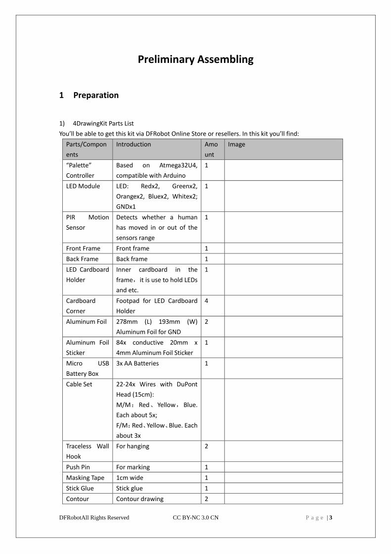
1) 4DrawingKit Parts List
You’ll be able to get this kit via DFRobot Online Store or resellers. In this kit you’ll find:
Parts/Compon
ents
Introduction Amo
unt
Image
“Palette”
Controller
Based on Atmega32U4,
compatible with Arduino
1
LED Module LED: Redx2, Greenx2,
Orangex2, Bluex2, Whitex2;
GNDx1
1
PIR Motion
Sensor
Detects whether a human
has moved in or out of the
sensors range
1
Front Frame Front frame 1
Back Frame Back frame 1
LED Cardboard
Holder
Inner cardboard in the
frame,it is use to hold LEDs
and etc.
1
Cardboard
Corner
Footpad for LED Cardboard
Holder
4
Aluminum Foil 278mm (L) 193mm (W)
Aluminum Foil for GND
2
Aluminum Foil
Sticker
84x conductive 20mm x
4mm Aluminum Foil Sticker
1
Micro USB
Battery Box
3x AA Batteries 1
Cable Set 22-24x Wires with DuPont
Head (15cm):
M/M:Red、Yellow,Blue.
Each about 5x;
F/M:Red、Yellow、Blue. Each
about 3x
Traceless Wall
Hook
For hanging 2
Push Pin For marking 1
Masking Tape 1cm wide 1
Stick Glue Stick glue 1
Contour Contour drawing 2
DFRobotAll Rights Reserved CC BY-NC 3.0 CN P a g e | 4
Drawing
Frame Dimension:352x274x30mm
Canvas Dimension:A4 (210 x 297mm)or 12 x 9inch(228.6 x 304.8mm)
Frame Window Dimension:287 x 200mm(smaller than A4)
Frame Material:Paperboard, corrugated paperboard
Power Supply:3xAA or micro-USB
Battery Life:30 days with AA batteries(In standby mode, all modules will shut down automatically
except zone W.)
LED Module Interface:4 Channel 40Ma I/O Interface(Zone Z),4 Channel 500mAOutputInterface(Zone
X)
Extension Interface:4 Channel 3PIN for Sensor/Actuator(Zone S)/1 Channel UART/1 Channel I2C
Wakeup Interface:1 Channel 3PIN for Sensor (Zone W)
2 Making the Frame
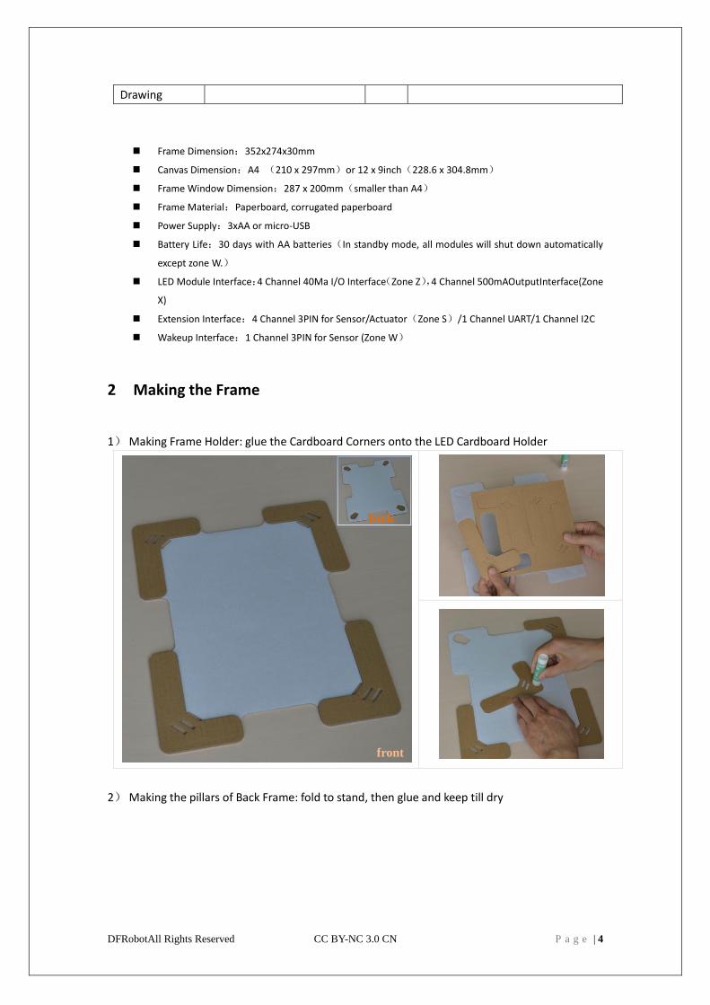
1) Making Frame Holder: glue the Cardboard Corners onto the LED Cardboard Holder
2) Making the pillars of Back Frame: fold to stand, then glue and keep till dry
front
back
DFRobotAll Rights Reserved CC BY-NC 3.0 CN P a g e | 5
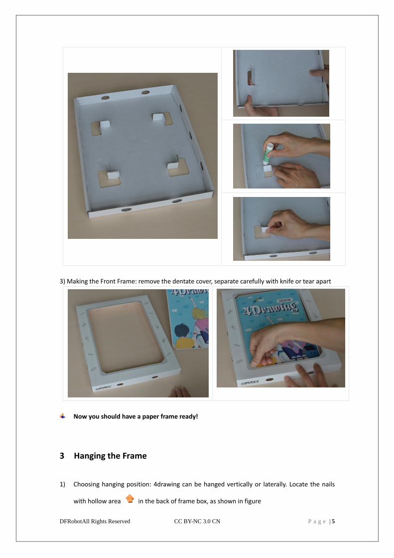
3) Making the Front Frame: remove the dentate cover, separate carefully with knife or tear apart
Now you should have a paper frame ready!
3 Hanging the Frame
1) Choosing hanging position: 4drawing can be hanged vertically or laterally. Locate the nails
with hollow area in the back of frame box, as shown in figure
DFRobotAll Rights Reserved CC BY-NC 3.0 CN P a g e | 6
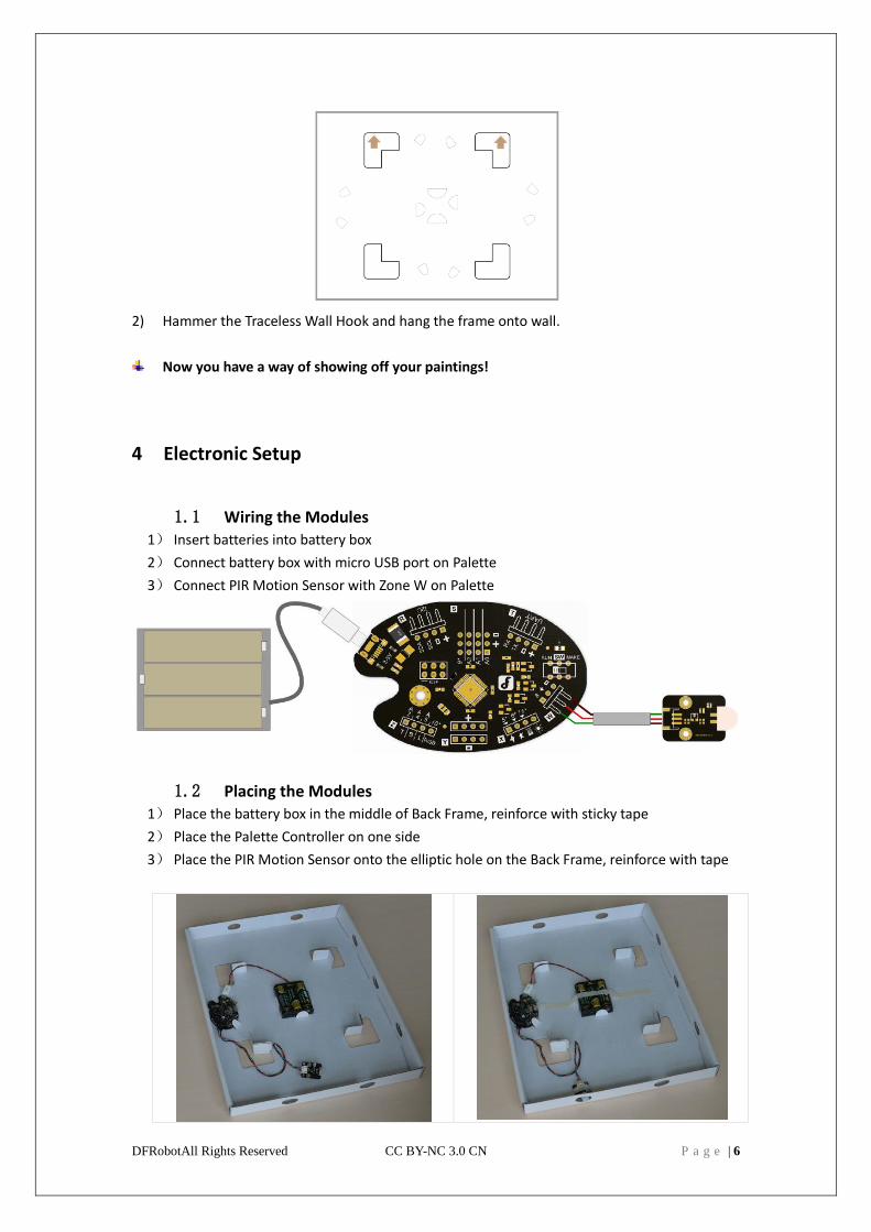
2) Hammer the Traceless Wall Hook and hang the frame onto wall.
Now you have a way of showing off your paintings!
4 Electronic Setup
1.1 Wiring the Modules 1) Insert batteries into battery box
2) Connect battery box with micro USB port on Palette
3) Connect PIR Motion Sensor with Zone W on Palette
1.2 Placing the Modules 1) Place the battery box in the middle of Back Frame, reinforce with sticky tape
2) Place the Palette Controller on one side
3) Place the PIR Motion Sensor onto the elliptic hole on the Back Frame, reinforce with tape
DFRobotAll Rights Reserved CC BY-NC 3.0 CN P a g e | 7
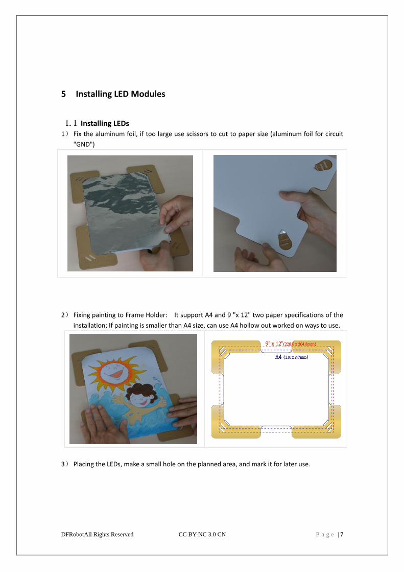
5 Installing LED Modules
1.1 Installing LEDs 1) Fix the aluminum foil, if too large use scissors to cut to paper size (aluminum foil for circuit
"GND")
2) Fixing painting to Frame Holder: It support A4 and 9 "x 12" two paper specifications of the
installation; If painting is smaller than A4 size, can use A4 hollow out worked on ways to use.
3) Placing the LEDs, make a small hole on the planned area, and mark it for later use.
DFRobotAll Rights Reserved CC BY-NC 3.0 CN P a g e | 8
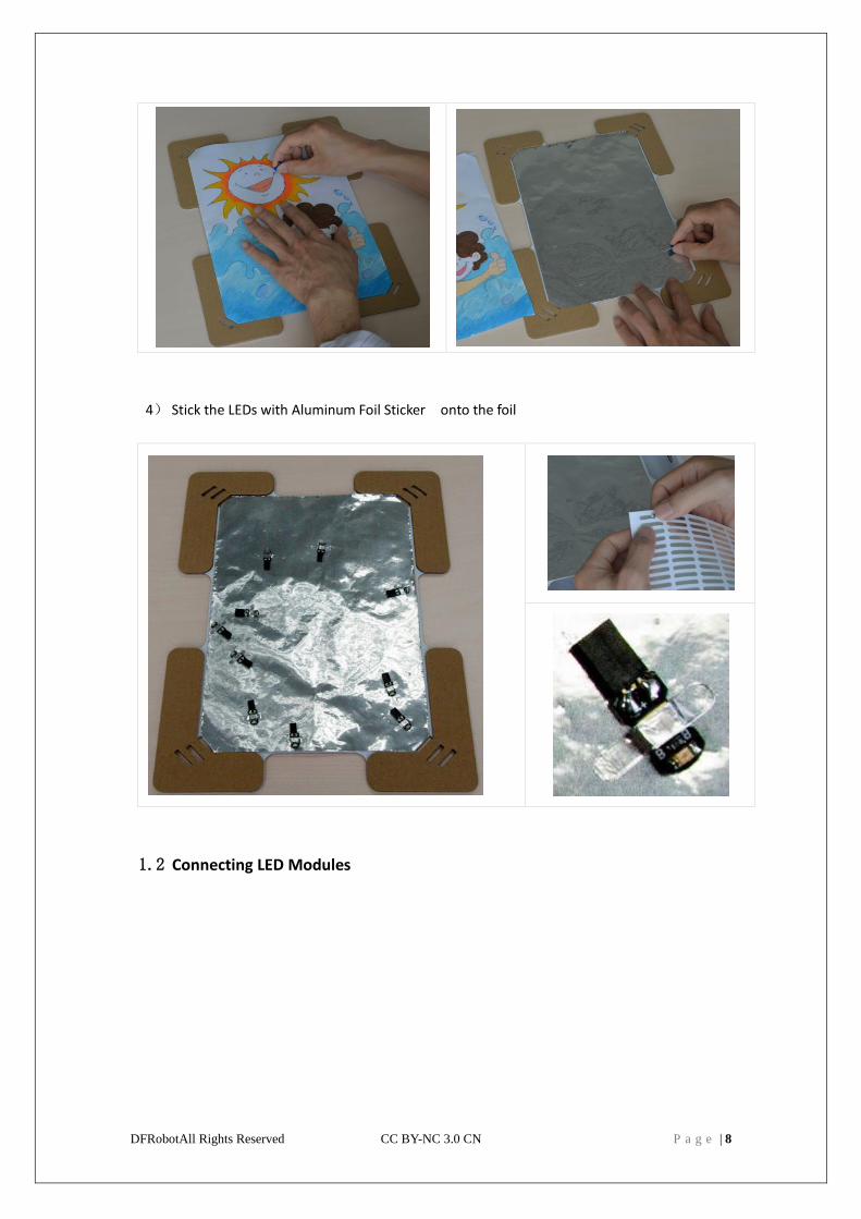
4) Stick the LEDs with Aluminum Foil Sticker onto the foil
1.2 Connecting LED Modules
DFRobotAll Rights Reserved CC BY-NC 3.0 CN P a g e | 9
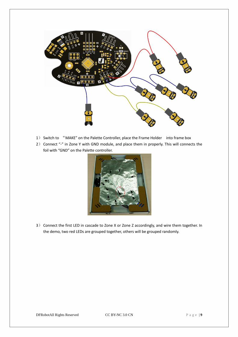
1) Switch to “MAKE” on the Palette Controller, place the Frame Holder into frame box
2) Connect “-” in Zone Y with GND module, and place them in properly. This will connects the
foil with “GND” on the Palette controller.
3) Connect the first LED in cascade to Zone X or Zone Z accordingly, and wire them together. In
the demo, two red LEDs are grouped together, others will be grouped randomly.
DFRobotAll Rights Reserved CC BY-NC 3.0 CN P a g e | 10
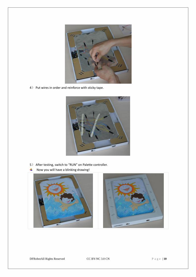
4) Put wires in order and reinforce with sticky tape.
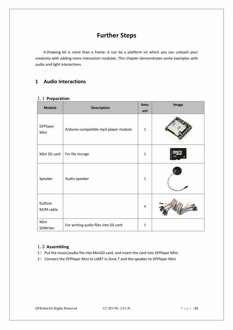
5) After testing, switch to “RUN” on Palette controller.
Now you will have a blinking drawing!
DFRobotAll Rights Reserved CC BY-NC 3.0 CN P a g e | 11
Further Steps
4-Drawing kit is more than a frame: it can be a platform on which you can unleash your
creativity with adding more interaction modules. This chapter demonstrates some examples with
audio and light interactions.
1 Audio Interactions
1.1 Preparation
Module Description Amo
unt
Image
DFPlayer
Mini Arduino-compatible mp3 player module 1
Mini SD card For file storage 1
Speaker Audio speaker 1
DuPont
M/M cable 4
Mini
SDWriter For writing audio files into SD card 1
1.2 Assembling 1) Put the music/audio file into MiniSD card, and insert the card into DFPlayer Mini.
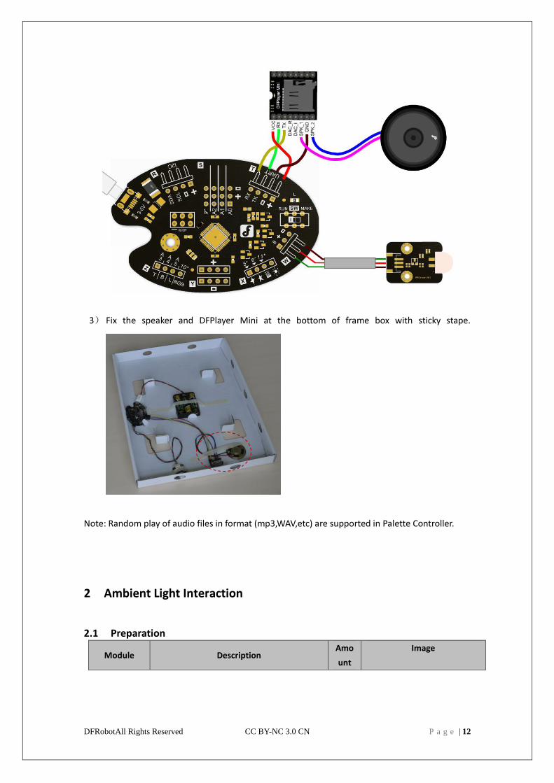
2) Connect the DFPlayer Mini to UART in Zone T and the speaker to DFPlayer Mini
DFRobotAll Rights Reserved CC BY-NC 3.0 CN P a g e | 12
3) Fix the speaker and DFPlayer Mini at the bottom of frame box with sticky stape.
Note: Random play of audio files in format (mp3,WAV,etc) are supported in Palette Controller.
2 Ambient Light Interaction
2.1 Preparation
Module Description Amo
unt
Image
DFRobotAll Rights Reserved CC BY-NC 3.0 CN P a g e | 13
Analog
Ambient
Light Sensor
This sensor can capture even the slightest
change of light. 1
2.2 Wiring
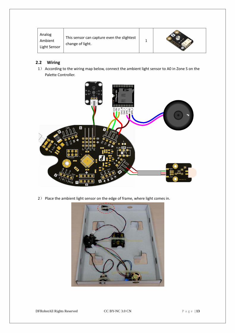
1) According to the wiring map below, connect the ambient light sensor to A0 in Zone S on the
Palette Controller.
2) Place the ambient light sensor on the edge of frame, where light comes in.
DFRobotAll Rights Reserved CC BY-NC 3.0 CN P a g e | 14
Note:When the analog input A0 is smaller than 1/100 of its peak value, the Palette Controller
will automatically switch to sleep mode, thus saving energy.Controlling & Programing
4Drawing supports three modes of controlling:
Mode Description Scenario Difficulty
Plug and Play Assembling the frame Using premade light/audio
interactions
Easy
Graphical
programming
1) Install Arduino IDE
2) Install Ardublock
3) Visual programming
4) Upload sketch
Using sensors and acturators in the
set.
Intermediate
Freestyle Make your own code
based on 4Drawing
sample code
Plug and control anything you like,
make magic!
Intermediate+
1 Plug & Play
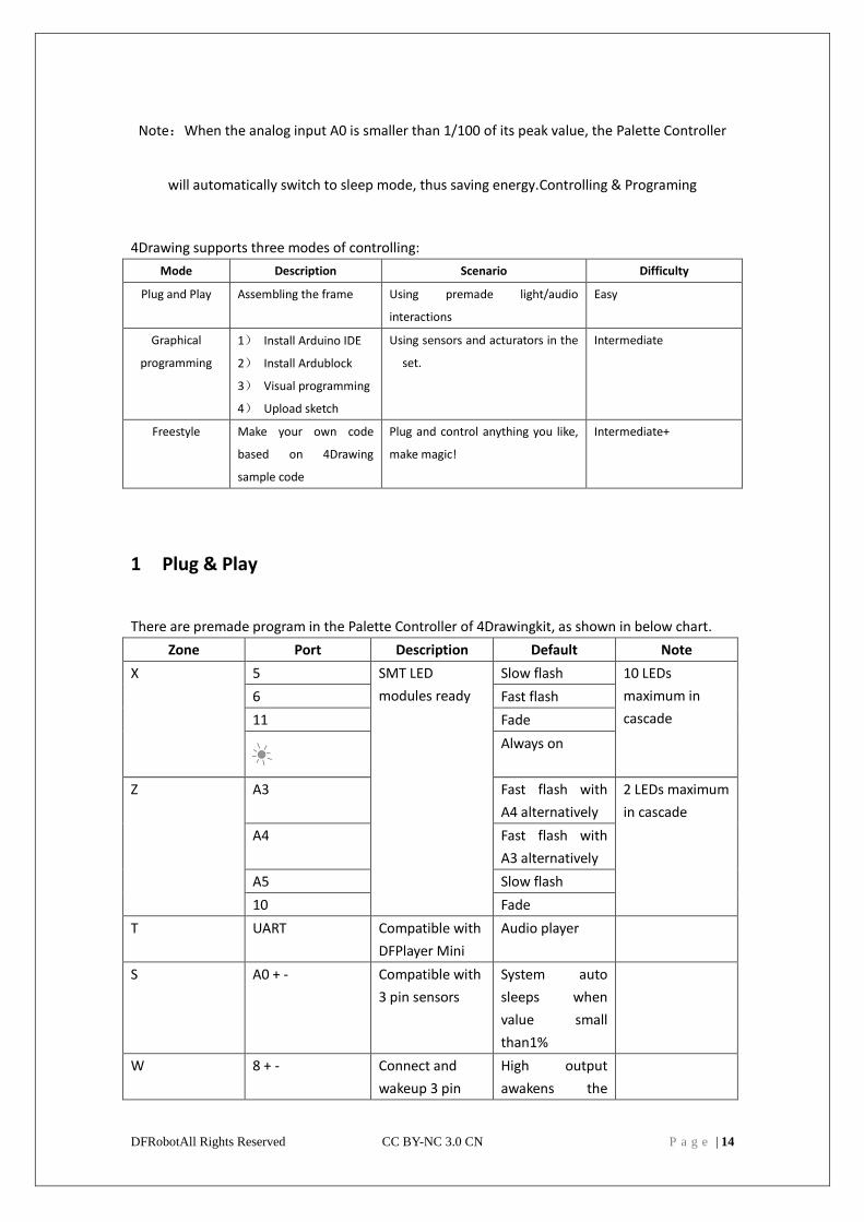
There are premade program in the Palette Controller of 4Drawingkit, as shown in below chart.
Zone Port Description Default Note
X 5 SMT LED
modules ready
Slow flash 10 LEDs
maximum in
cascade
6 Fast flash
11 Fade
Always on
Z A3 Fast flash with
A4 alternatively
2 LEDs maximum
in cascade
A4 Fast flash with
A3 alternatively
A5 Slow flash
10 Fade
T UART Compatible with
DFPlayer Mini
Audio player
S A0 + - Compatible with
3 pin sensors
System auto
sleeps when
value small
than1%
W 8 + - Connect and
wakeup 3 pin
High output
awakens the
DFRobotAll Rights Reserved CC BY-NC 3.0 CN P a g e | 15
sensor system
2 Graphical Programming
Ardublock is an opensource software based on Arduino IDE, more information please
checkhttp://blog.ardublock.com/
2.1 Preparation
Module Description Amount Image
PC Installing and running
program 1
MicroUSB Cable Communication 1
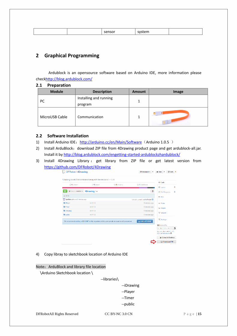
2.2 Software Installation
1) Install Arduino IDE:http://arduino.cc/en/Main/Software(Arduino 1.0.5 )
2) Install ArduBlock:download ZIP file from 4Drawing product page and get ardublock-all.jar.
Install it by http://blog.ardublock.com/engetting-started-ardublockzhardublock/
3) Install 4Drawing Library : get library from ZIP file or get latest version from
https://github.com/DFRobot/4Drawing
4) Copy libray to sketchbook location of Arduino IDE
Note:ArduBlock and library file location
\Arduino Sketchbook location \
--libraries\
--iDrawing
--Player
--Timer
--public
DFRobotAll Rights Reserved CC BY-NC 3.0 CN P a g e | 16
--tools\ArduBlockTool\tool\
--ardublock-all.jar
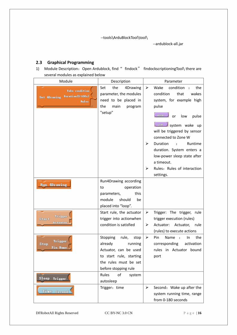
2.3 Graphical Programming
1) Module Description:Open Ardublock, find“ findock” findockscriptioningTool\ there are
several modules as explained below
Module Description Parameter
Set the 4Drawing
parameter, the modules
need to be placed in
the main program
"setup"
Wake condition : the
condition that wakes
system, for example high
pulse
or low pulse
system wake up
will be triggered by sensor
connected to Zone W
Duration : Runtime
duration. System enters a
low-power sleep state after
a timeout.
Rules:Rules of interaction
settings.
Run4Drawing according
to operation
parameters, this
module should be
placed into “loop”.
Start rule, the actuator
trigger into actionwhen
condition is satisfied
Trigger: The trigger, rule
trigger execution (rules)
Actuator: Actuator, rule
(rules) to execute actions
Stopping rule, stop
already running
Actuator, can be used
to start rule, starting
the rules must be set
before stopping rule
Pin Name : In the
corresponding activation
rules in Actuator bound
port
Rules of system
autosleep
Trigger:time Second:Wake up after the
system running time, range
from 0-180 seconds
DFRobotAll Rights Reserved CC BY-NC 3.0 CN P a g e | 17
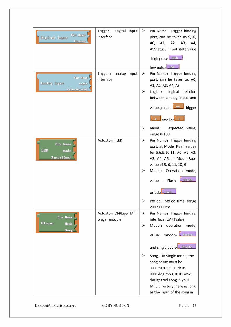
Trigger : Digital input
interface
Pin Name:Trigger binding
port, can be taken as 9,10,
A0, A1, A2, A3, A4,
A5Status:input state value
-high pulse
low pulse
Trigger : analog input
interface
Pin Name:Trigger binding
port, can be taken as A0,
A1, A2, A3, A4, A5
Logic : Logical relation
between analog input and
values,equal bigger
smaller
Value : expected value,
range 0-100
Actuator:LED Pin Name:Trigger binding
port; at Mode=Flash values
for 5,6,9,10,11, A0, A1, A2,
A3, A4, A5; at Mode=Fade
value of 5, 6, 11, 10, 9
Mode : Operation mode,
value - Flash
orfade
Period:period time, range
200-9000ms
Actuator:DFPlayer Mini
player module
Pin Name:Trigger binding
interface, UARTvalue
Mode : operation mode,
value: random
and single audio
Song:In Single mode, the
song name must be
0001*-0199*, such as
0001dog.mp3, 0101.wav;
designated song in your
MP3 directory; here as long
as the input of the song in
DFRobotAll Rights Reserved CC BY-NC 3.0 CN P a g e | 18
front of the four numbers
can be, for example the
0001dog.mp3 input 0001
and 0101.wav input 0101
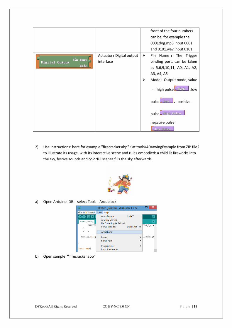
Actuator:Digital output
interface
Pin Name : The Trigger
binding port, can be taken
as 5,6,9,10,11, A0, A1, A2,
A3, A4, A5
Mode:Output mode, value
– high pulse 、low
pulse 、positive
pulse
negative pulse
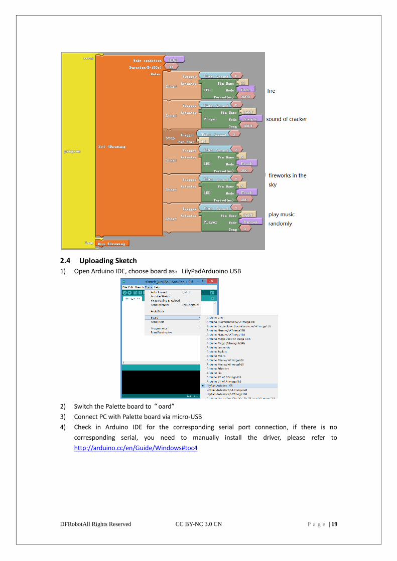
2) Use instructions: here for example "firecracker.abp"(at tools\4DrawingExample from ZIP file)
to illustrate its usage, with its interactive scene and rules embodied: a child lit fireworks into
the sky, festive sounds and colorful scenes fills the sky afterwards.
a) Open Arduino IDE,select Tools - Ardublock
b) Open sample“firecracker.abp”
DFRobotAll Rights Reserved CC BY-NC 3.0 CN P a g e | 19
2.4 Uploading Sketch
1) Open Arduino IDE, choose board as:LilyPadArduoino USB
2) Switch the Palette board to“oard”
3) Connect PC with Palette board via micro-USB
4) Check in Arduino IDE for the corresponding serial port connection, if there is no
corresponding serial, you need to manually install the driver, please refer to
http://arduino.cc/en/Guide/Windows#toc4
DFRobotAll Rights Reserved CC BY-NC 3.0 CN P a g e | 20
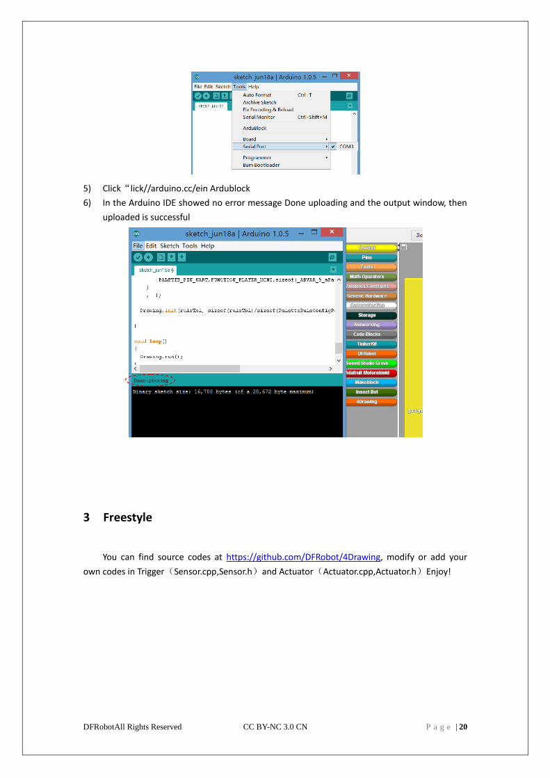
5) Click“lick//arduino.cc/ein Ardublock
6) In the Arduino IDE showed no error message Done uploading and the output window, then
uploaded is successful
3 Freestyle
You can find source codes at https://github.com/DFRobot/4Drawing, modify or add your
own codes in Trigger(Sensor.cpp,Sensor.h)and Actuator(Actuator.cpp,Actuator.h)Enjoy!