Embed Size (px)
Citation preview

1
4th and 5th Axis Rotary Table
Team: Dakota Bass Ricky Riedl
Nicole Slagle Irene Yee
Sponsors:
Martin Koch
Dr. Jose Macedo
Mechancical Engineering Department California Polytechnic State University
San Luis Obispo 2016

2
Statement of Disclaimer
Since this project is a result of a class assignment, it has been graded and accepted as fulfillment of the course requirements. Acceptance does not imply technical accuracy or reliability. Any use of information in this report is done at the risk of the user. These risks may include catastrophic failure of the device or infringement of patent or copyright laws. California Polytechnic State University at San Luis Obispo and its staff cannot be held liable for any use or misuse of the project.

3
ContentsExecutive Summary ........................................................................................................................ 8
1. Introduction ................................................................................................................................. 9
1.1 Sponsor Background ............................................................................................................. 9
1.2 Formal Project Definition ..................................................................................................... 9
1.3 Objectives ............................................................................................................................. 9
1.4 Project Management ............................................................................................................. 9
2. Background ............................................................................................................................... 10
2.1 History................................................................................................................................. 10
2.2 Existing Products ................................................................................................................ 10
2.3 Patents ................................................................................................................................. 11
2.4 Component Research .......................................................................................................... 12
2.4.1 Backlash Reduction ..................................................................................................... 12
2.4.2 Motors .......................................................................................................................... 14
2.4.3 Bearings ....................................................................................................................... 19
3. Design Development ................................................................................................................. 20
3.1 Requirements/Specifications............................................................................................... 20
3.2 Concept Generation ............................................................................................................ 21
3.3 Initial Design Considerations .............................................................................................. 23
3.3.1 Support Design............................................................................................................. 23
4. Final Design .............................................................................................................................. 27
4.1 Overall Layout .................................................................................................................... 27
4.2 Detailed Design ................................................................................................................... 27
4.2.1 Cap ............................................................................................................................... 28
4.2.2 Housing ........................................................................................................................ 28
4.2.3 Platter ........................................................................................................................... 28
4.2.4 Shaft ............................................................................................................................. 28
4.2.5 Gear Preload................................................................................................................. 29
4.2.6 Worm Wheel ................................................................................................................ 29
4.3 Analysis Results .................................................................................................................. 30
4.3.1 Drive Shaft ................................................................................................................... 30
4.3.2 Driven Shaft ................................................................................................................. 30

4
4.3.3 Inertia ........................................................................................................................... 30
4.3.4 Worm Gear A and B .................................................................................................... 30
4.3.5 Bearings ....................................................................................................................... 30
4.3.6 Bolts ............................................................................................................................. 30
4.3.7 Summary ...................................................................................................................... 31
4.4 Cost Analysis ...................................................................................................................... 31
5. Product Realization ................................................................................................................... 32
5.1 Manufacturing ..................................................................................................................... 32
5.2 Design Edits ........................................................................................................................ 37
5.3 Recommendations for Future Manufacturing ..................................................................... 38
6. Design Verification Plan ........................................................................................................... 39
6.1 DVP&R ............................................................................................................................... 39
6.2 Vibration Testing ................................................................................................................ 39
6.3 Backlash Testing ................................................................................................................. 41
6.3 Tolerance Testing................................................................................................................ 41
6.4 Efficiency Testing ............................................................................................................... 44
6.5 Gear Wear Testing .............................................................................................................. 44
7. Conclusions and Recommendations ......................................................................................... 45
References ..................................................................................................................................... 46
Appendices .................................................................................................................................... 48
A: Specifications List ................................................................................................................ 48
B: Detailed Drawings ................................................................................................................ 48
C: Structured BOM ................................................................................................................... 48
D: Component Specification Sheets ......................................................................................... 48
E: EES Formatted Calculations ................................................................................................ 48
F: FMEA and Design Verification ............................................................................................ 48
G: Gantt Chart ........................................................................................................................... 48

5
ListofFiguresFigure 1. Haas OM-2 (Haas) ........................................................................................................... 9 Figure 2. Haas TRT 100 (Haas) .................................................................................................... 10 Figure 3. Nikken 5AX-130FA (Nikken) ....................................................................................... 10 Figure 4. Anti-Backlash Mechanism Patent Design (Mauro) ....................................................... 11 Figure 5. Rotary Table Bearing Patent Design (Bullard) ............................................................. 11 Figure 6. Rotary Table Apparatus Patent Design (Kato) .............................................................. 11 Figure 7. Manufacturers in Japan use blue ink to machine precision ground gears (Mitzubishi) 12 Figure 8. Cone drive manufactured by Cone Drive Solutions (Cone Drive) ................................ 12 Figure 9. Duplex worm gear drawing provided by Allytech (Allytech) ....................................... 12 Figure 10. Split gear (Machine Design) ........................................................................................ 12 Figure 11. Manually adjusted worm drive .................................................................................... 13 Figure 12. Spring loaded spur gears to reduce backlash (Machine Design) ................................. 13 Figure 13. SGMJV AC Servo Motor (Yaskawa) .......................................................................... 14 Figure 14. Cutting Torque Data .................................................................................................... 15 Figure 15. Cutting Force Distribution ........................................................................................... 15 Figure 16. Velocity Profile for Both Axes (Yaskawa) ................................................................ 16 Figure 17. Axis A Motor Performance and Operating Point ........................................................ 16 Figure 18. Axis B Motor Performance and Operating Point ........................................................ 17 Figure 19. NEMA 23 Stepper Motor ............................................................................................ 19 Figure 20. Back to back bearing configuration ............................................................................. 20 Figure 21. NSK angular contact bearings ..................................................................................... 20 Figure 22. Geometry Configuration, Cantilever-Cantilever and Cantilever-Fixed ...................... 24 Figure 23. Cantilever spring forcer ............................................................................................... 25 Figure 24. Worm gear backlash reduction system ........................................................................ 25 Figure 25. Method to reduce backlash in worm drive .................................................................. 25 Figure 26. Tapered Roller Bearings .............................................................................................. 26 Figure 27. Thrust bearing .............................................................................................................. 26 Figure 28. Gen5 rotary table with motor placement ..................................................................... 26 Figure 29. Completed prototype 1 ................................................................................................ 27 Figure 30. Rotary Schematic......................................................................................................... 28 Figure 31. Gear preload system .................................................................................................... 29 Figure 32. Rendering of rotary exploded view ............................................................................. 29 Figure 33. Housing Maching Set Up ............................................................................................ 34 Figure 34. Housing inspection ...................................................................................................... 34 Figure 35. Spindle Machining ....................................................................................................... 35 Figure 36. Spindle Assembly ........................................................................................................ 36 Figure 37. Perpendicularity Measurement .................................................................................... 37 Figure 38. Custom stepper motor controller ................................................................................. 38 Figure 39. Laboratory setup diagram ............................................................................................ 40 Figure 40. Accelerometer mounting configuration on housing with components removed ......... 40 Figure 41. Housing mounted to the shake table ............................................................................ 40

6
Figure 42. Results of vibration testing completed on the housing alone. ..................................... 41 Figure 43. Setup to measure flatness ............................................................................................ 42 Figure 44. Setup for measuring run-out tolerance ........................................................................ 43
7
ListofTables Table 1. Comparing Backlash Reduction Options (Machine Design) .......................................... 14 Table 2. Axis B SigmaSelect Summary ........................................................................................ 17 Table 3. Axis A SigmaSelect Summary ....................................................................................... 18 Table 4. Yaskawa Motor Specs .................................................................................................... 19 Table 5. Reduced specifications list used for concept generation ................................................ 21 Table 6. Morphological matrix used to group solutions for concept generation .......................... 22 Table 7. List of chosen concepts from the morphological matrix. ............................................... 22 Table 8. Decision Matrix evaluating each concept according to important criteria ..................... 23 Table 9. Decision Matrix for Backlash Reduction Methods ......................................................... 24 Table 10. Factors of Safety for Components ................................................................................ 31 Table 11. Complete list of parts and cost for both rotaries ........................................................... 32 Table 13. Stackup Chain ............................................................................................................... 33

8
Executive Summary Dr. Jose Macedo and Professor Martin Koch of the IME department saw that there was no available 5th axis rotaries compatable with smaller CNC machines, and desired one in order machine more complex wax patterns for lost wax casting. Commercial 5th axis rotaries typically cost around 30,000 USD, which is quite an investment for smaller institutions and so our sponsors Koch tasked our team with designing, building, and testing a 5th axis rotary table that will match commercial specifications at much lower, aproachable price point. The project began by researching existing rotaries and developing a list of technical specifications that the design must satisfy. Using these criteria, a preliminary design was created and initial calculations were performed to verify the design. The first prototype was manufactured and after performing a few tests, changes for improving our next generation design was determined. The design went through a complete overhaul, and a new prototype that was more robust and better designed for manufacturing was machined using CNC machines. Based of testing results, each rotary stage has a natural frequency of about 400 Hz, which should be avoided when used for machining. A 4th axis rotary table using a Haas specific Yaskawa motor was made as well as a complete 5th axis rotary table. Over the course of the last quarter, the choice of motor changed due to sponsor-related circumstances, and so the resulting 5th axis design was chosen to be driven by two stepper motor and an external controller that works in conjunction with a G-code macro.
9
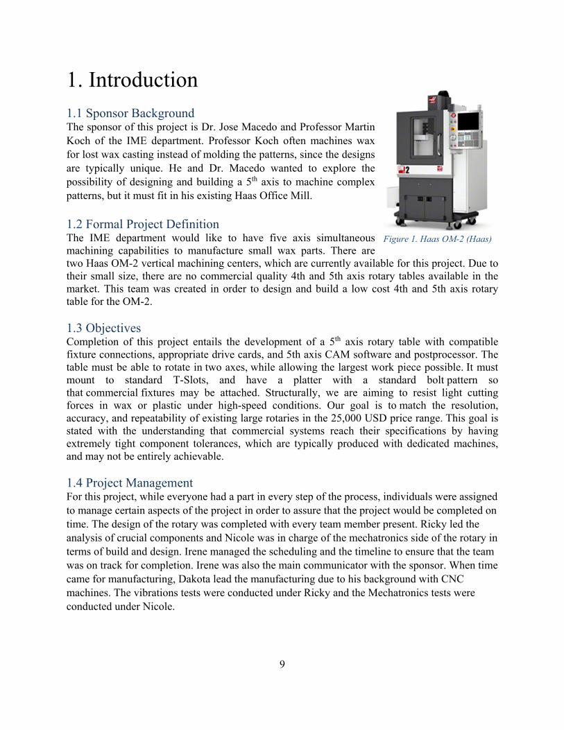
Figure 1. Haas OM-2 (Haas)
1. Introduction
1.1 Sponsor Background The sponsor of this project is Dr. Jose Macedo and Professor Martin Koch of the IME department. Professor Koch often machines wax for lost wax casting instead of molding the patterns, since the designs are typically unique. He and Dr. Macedo wanted to explore the possibility of designing and building a 5th axis to machine complex patterns, but it must fit in his existing Haas Office Mill.
1.2 Formal Project Definition The IME department would like to have five axis simultaneous machining capabilities to manufacture small wax parts. There are two Haas OM-2 vertical machining centers, which are currently available for this project. Due to their small size, there are no commercial quality 4th and 5th axis rotary tables available in the market. This team was created in order to design and build a low cost 4th and 5th axis rotary table for the OM-2. 1.3 Objectives Completion of this project entails the development of a 5th axis rotary table with compatible fixture connections, appropriate drive cards, and 5th axis CAM software and postprocessor. The table must be able to rotate in two axes, while allowing the largest work piece possible. It must mount to standard T-Slots, and have a platter with a standard bolt pattern so that commercial fixtures may be attached. Structurally, we are aiming to resist light cutting forces in wax or plastic under high-speed conditions. Our goal is to match the resolution, accuracy, and repeatability of existing large rotaries in the 25,000 USD price range. This goal is stated with the understanding that commercial systems reach their specifications by having extremely tight component tolerances, which are typically produced with dedicated machines, and may not be entirely achievable. 1.4 Project Management For this project, while everyone had a part in every step of the process, individuals were assigned to manage certain aspects of the project in order to assure that the project would be completed on time. The design of the rotary was completed with every team member present. Ricky led the analysis of crucial components and Nicole was in charge of the mechatronics side of the rotary in terms of build and design. Irene managed the scheduling and the timeline to ensure that the team was on track for completion. Irene was also the main communicator with the sponsor. When time came for manufacturing, Dakota lead the manufacturing due to his background with CNC machines. The vibrations tests were conducted under Ricky and the Mechatronics tests were conducted under Nicole.

10
2. Background
2.1 History Over the past two decades, the machine tool industry has been experiencing a shift toward lighter, smaller CNC machine tools (Arnold). Advancements in spindle tapers and grinding accuracy have allowed small taper machines to compete with large machines. Popular small taper standards include HSK, BT-30, and BT-30 Dual Contact spindles (All Industrial). This shift towards smaller machines has been caused by the ability of such tapers to take higher cutting forces than before. Also, high speed machining allows for the material removal rate (MRR) of these tools to match the MRR of larger machines (Albert).
The trend towards smaller CNC machines in industry has lowered the cost of small table size / small taper vertical machining centers to approximately 50,000 USD (Haas). At the same time, advances in CAM software have made programming parts simpler than ever before. More consumer groups, such as high schools, light industry, universities, and dental practices are capitalizing on the availability of these CNC machine tools. 2.2 Existing Products A concurrent trend in industry has been the utilization of 5th axis rotaries. Aftermarket 5th axis rotary tables can be bought for around 30,000 USD and add two additional axes to the three existing axes of a CNC machine. This allows parts to be machined more accurately in fewer setups while enabling the manufacturing of more complex parts. In many situations, purchasing a 5th axis table can be a profitable business decision (Sherman). However, commercial quality 5th axis rotary tables are not as available for the smaller machine market. Typical manufacturers of
5th axis tables include Lyndex-Nikken, Haas Automation, Tsudakoma, and Matsumoto. Their 5th axis tables are not designed for machines with small table sizes, such as the Haas OM-2.
Rotaries within the budget of small organizations are oversized and too heavy for smaller CNC machines. There is a desire for small 5th axis rotary tables for small table sizes and low cutting forces, which could bridge the gap between hobbyist tables and industrial tables. In the Cal Poly IME 141 lab, Haas OM-2 CNC machines are utilized to make wax shapes for sand casting. For wax and soft plastic machining, there is a niche for accurate, but small 5th axis rotaries.
Figure 2. Haas TRT 100 (Haas)
Figure 3. Nikken 5AX-130FA (Nikken)

11
2.3 Patents Below are a few patents relevant to our design.
Patent 6,016,716 This is a patent for reducing backlash in a worm gear drive. The user must manually dial in the setscrew to adjust the contact between the worm and the gear. Over time, the setscrew must be reset.
Patent 828,876 Bullard’s rotary patent uses an external oil port to keep the rotating contact points submerged at all times. This decreases the effects of wear on the rotary over time and minimized maintenance.
Patent US 7,603,930 B2 The Rotary Table Apparatus is essentially a fourth and fifth axis rotary table. This design focuses on small and light-weight properties.
Figure 4. Anti-Backlash Mechanism Patent Design (Mauro)
Figure 5. Rotary Table Bearing Patent Design (Bullard)
Figure 6. Rotary Table Apparatus Patent Design (Kato)
12
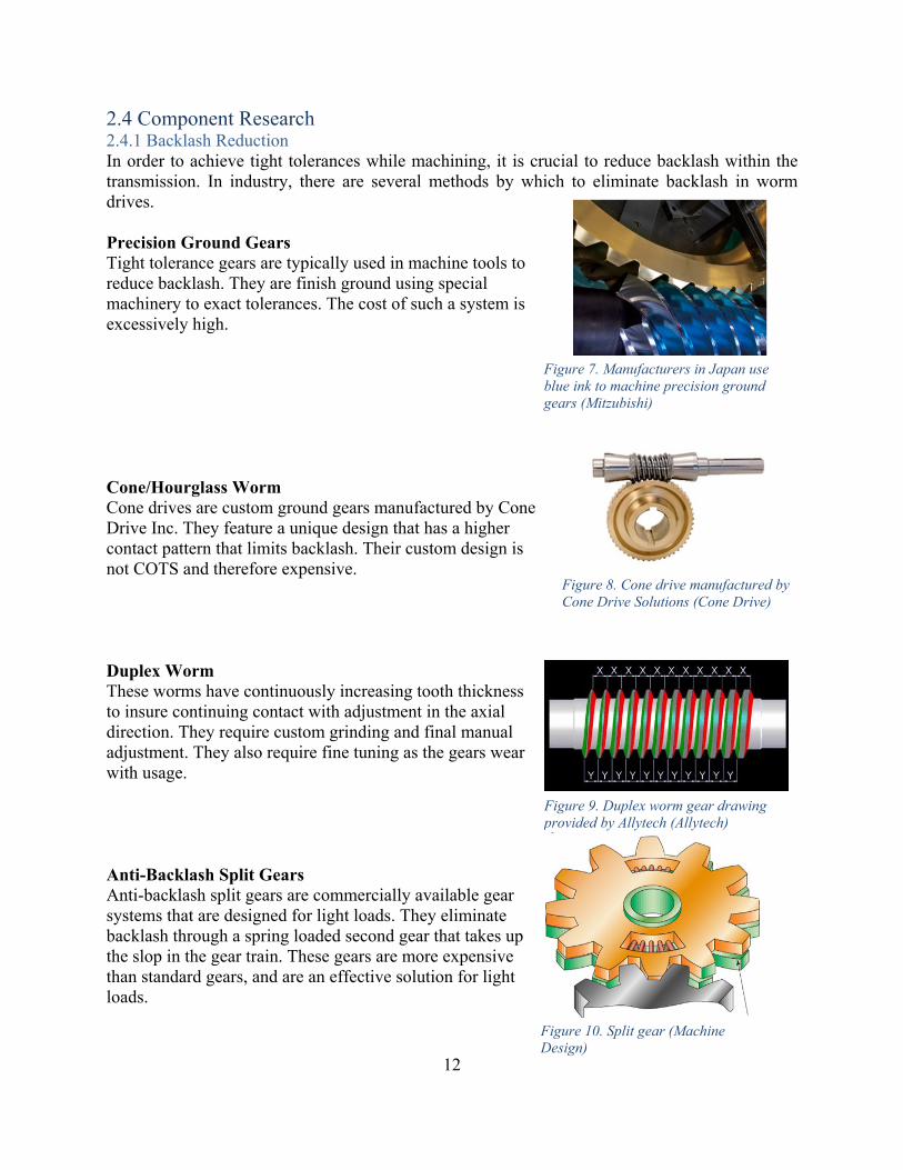
2.4 Component Research 2.4.1 Backlash Reduction In order to achieve tight tolerances while machining, it is crucial to reduce backlash within the transmission. In industry, there are several methods by which to eliminate backlash in worm drives. Precision Ground Gears Tight tolerance gears are typically used in machine tools to reduce backlash. They are finish ground using special machinery to exact tolerances. The cost of such a system is excessively high. Cone/Hourglass Worm Cone drives are custom ground gears manufactured by Cone Drive Inc. They feature a unique design that has a higher contact pattern that limits backlash. Their custom design is not COTS and therefore expensive. Duplex Worm These worms have continuously increasing tooth thickness to insure continuing contact with adjustment in the axial direction. They require custom grinding and final manual adjustment. They also require fine tuning as the gears wear with usage. Anti-Backlash Split Gears Anti-backlash split gears are commercially available gear systems that are designed for light loads. They eliminate backlash through a spring loaded second gear that takes up the slop in the gear train. These gears are more expensive than standard gears, and are an effective solution for light loads.
Figure 7. Manufacturers in Japan use blue ink to machine precision ground gears (Mitzubishi)
Figure 8. Cone drive manufactured by Cone Drive Solutions (Cone Drive)
Figure 9. Duplex worm gear drawing provided by Allytech (Allytech)
Figure 10. Split gear (Machine Design)

13
Manually Adjusted Gear Mesh Manually dialing in a worm drive is common practice for manual rotary tables. The worm is adjusted via a set screw that brings the worm and gear into each other. This allows radial locational adjustment to counteract manufacturing errors. The “Anti-Backlash Mechanism for a Rotary Stage” patent by George Mauro depicts this design and is further described in the Patent section of this report. Spring Loaded Gear Mesh Spring loaded gear meshes force the teeth of gears into constant contact via a spring force. This accounts for variations in diameter along the outer profile of the gears. Table 1 shows the three main criteria for backlash reduction options. As with many components, there is a balance between cost and quality that must be analyzed. Each method is suited for different types of applications and used in certain types of systems. In addition, each solution has differing amounts of backlash reduction.
Figure 11. Manually adjusted worm drive
Figure 12. Spring loaded spur gears to reduce backlash (Machine Design)

14
2.4.2 Motors Each axis must be controlled independently, which requires two motors and a controller. From collaboration with Haas Automation and Yaskawa, we were initially advised to choose among the Yaskawa SGMJV motor series to be compatible with the Haas controller. Unfortunately, months later, we found out that the SGMJV motors are not compatible with the Haas controller. Instead, we were given proprietary 200-watt motors. The rest of this section includes the design process of sizing a SGMJV motor, which were ultimately not used in this project, but useful in sizing the appropriate NEMA stepper motors and for further advancements on this project. In order to calculate the required motor torque, the cutting force was experimentally determined. A 2 flute 3/8” endmill was used to machine wax with a .250” depth of cut in a full slotting machining operation. The machine torque was measured using a load meter and a large amount of data (32 pcs) was collected at random time intervals. The load of the spindle motor when it was not cutting was also collected to account for inertial effects.
Table 1. Comparing Backlash Reduction Options (Machine Design)
Figure 13. SGMJV AC Servo Motor (Yaskawa)

15
Following this, we knew that the cutting torque was 0.25Nm as seen by the workpiece. The radius of our tool was 3.76mm, which allows us to calculate the cutting force distribution as shown below.
Assuming six standard deviations, the max cutting force is 80 Newtons. With a 100mm platter diameter, the torque seen by the gear train is 4Nm for the B axis, and 8Nm for the A axis. In addition to cutting forces, the table velocity profile must be specified in order to size a motor. The velocity profile below shows the table accelerating to 100 rpm in 0.5 seconds and switching directions after a one-hour interval. This is considered our worst-case scenario motor operation.
Figure 14. Cutting Torque Data
Figure 15. Cutting Force Distribution

16
After determining the operating point, the SigmaSelect program offered by Yaskawa was used to size the motors. SigmaSelect inputs are applied torque, inertia, speed, efficiency, gear ratio, and velocity profile. Outputs include motor recommendations and sizing options. The following tables are inputs and outputs for the SigmaSelect program. Furthermore, Yaskawa engineers recommended specifying an oil seal to prevent small contaminants from entering the motor. In the motor performance curves below, the dotted line refers to the 20% due to the oil seal.
Figure 16. Velocity Profile for Both Axes (Yaskawa)
Figure 17. Axis A Motor Performance and Operating Point

17
Motor performance charts for axis A and B show the worst-case operating point within continuous operation rating. According to SigmaSelect results, the factor of safety in the intermittent range for Axis A is 3.18 and axis B is 3.19.
To better summarize inputs and outputs, the tables below summarize results from SigmaSelect. Table 2. Axis B SigmaSelect Summary
Rotary Axis, B
Category Parameters Units Value External Forces Cutting Force N 80
Applied Torque Nm 4
Geometry Table Diameter m 0.1 Calculated Inertia Total Inertia at Motor kg*m2 3.45E‐06
Kinetic Profile Acceleration sec 0.5 Top Speed rpm 100 Deceleration sec 0.5 Run Time min 120
Gearing Gear Efficiency ‐ 0.5 Gear Reduction ‐ 30
Power Minimum Power W 83.8
Sigma Select Results Required Torque Nm 0.272 Required Speed rpm 3000 Required Power W 85.5
A SigmaSelect simulation was performed for each axis operating point since inertia and torque values are different. Axis A, the tilt axis, requires twice the torque and significantly more inertia.
Figure 18. Axis B Motor Performance and Operating Point

18
Table 3. Axis A SigmaSelect Summary
Tilt Axis, A Category Parameters Units Value
External Forces Cutting Force N 80 Applied Torque Nm 8
Geometry Part Height m 0.1 Calculated Inertia Total Inertia at Motor kg*m2 1.04E‐04
Kinetic Profile Acceleration sec 0.5 Top Speed rpm 100 Run Time min 120
Gearing Gear Efficiency ‐ 0.5 Gear Reduction ‐ 30
Power Minimum Power W 167.6
Sigma Select Results Required Torque Nm 0.541 Required Speed rpm 3000 Required Power W 170.0
It is also important to consider inertial effects on the motor accuracy. As the load inertia increases, the motor has more trouble keeping accuracy when positioning. Each motor is rated for an acceptable inertia, as shown in the Yaskawa Motor Specs table. Though our predicted inertias are below allowable, it is important to will test for inaccuracies with the closed loop system before finalizing the rotary.

19
Table 4. Yaskawa Motor Specs
Motors
SGMJV‐01A3A6S SGMJV‐02A3A6S Torque (Nm) Rated 0.2544 0.5096
Peak 0.888 1.784 Speed (rpm) Rated 3000 3000
Max 6000 6000 Inertia (x10‐4kg*m2) Motor 0.0665 0.259
Allowable 1.33 3.885 Body Dim (mm, kg) Length 82.5 80
Width 40 60 Height 40 60 Weight 0.4 0.9
Shaft Dim. (mm) Diameter 8 8 Length 25 25
Electronics Power (W) 100 200 Voltage (V) 200 200 Encoder 20 Bit Absolute 20 Bit Absolute
To summarize, the SGMJV 100 and 200 Watt motors are appropriate for the axes B and A, respectively. These motors are conveniently small at only 1-2 lbs and under 3” long. Despite the extensive design exercise in sizing the right motor, we were given two 200-watt motors without any drawings or motor performance specifications. It is highly recommended not to use these motors until further specifications are obtained for each.
Fortunately, we can use our simulation data to source a stepper motor with the appropriate amount of torque. Although stepper motors run much slower than AC servo motors, as long as the torque is sufficient, the rotary will still function. Also, it is important to consider that stepper motors do not have built-in encoders, and will not be as accurate as closed-loop systems.
2.4.3 Bearings Bearings are critical for our design in terms of minimizing run-out and providing the precision we need for our rotary table. Because of this, our rotary table requires bearings specifically designed for machine tools. General practice in the machine tool industry is to use two back-to-back angular contact thrust ball bearings.
Figure 19. NEMA 23 Stepper Motor

20
The preload between angular contact bearings is achieved by clamping a pair of bearings together. Preload increases rigidity, but consequently, it reduces rated speed. Preload also eliminates radial and axial play, increases accuracy and helps to prevent ball skid at high-speed. For our application, at a speed of 100 rpm, a large preload is best. For our spindle the NSK 7006C Series bearings are applicable for our rotary table. They are also easily accessible for ordering. Assembly using NSK bearings require narrow tolerances for fit, and so to dimension the shaft and housing placement of the bearings, we referred to the manufacturer’s recommendations. The specifications for these bearings are located in Appendix D.
3. Design Development 3.1 Requirements/Specifications After meeting with our sponsors, we determined a list of customer requirements. The 5th axis rotary table should:
Work with small Haas CNC machines on light duty machining of wax-type materials at normal production cutting speeds
Be capable of meeting or exceeding the speeds and accuracies of commercial 5th axis rotaries in the ~$25,000 price range
Include a way to home the 5th axis mechanism Be safe for human operators Incorporate appropriately sized servomotors from Yaskawa
Figure 20. Back to back bearing configuration
Figure 21. NSK angular contact bearings

21
In addition to the customer requirements, we created a specifications list to incorporate engineering specifications from which we used to start design process. A reduced list of specifications used for considering preliminary designs is shown below in Table 5. The full specifications list can be seen in Appendix A. The specifications were developed from evaluating constraints of the OM2, comparing specifications from existing products, measured loads, and operating conditions.
Table 5. Reduced specifications list used for concept generation
Number Feature Value Unit Source Compliance Engineering
Risk
1. Geometry
1.3 Max Work Table Height 4 in OM2 Specs Inspection Medium
1.4 Max Rotary Height 10 in OM2 Specs Inspection Low
1.5B Work Area Diameter 3 in Rotary Comparison Inspection Low
1.6B Max Work Piece Height 3 in Rotary Comparison Inspection Low
2. Kinematics
2.1 Rotational Speed 30 rpm Rotary Comparison Test High
2.2 Tilt Speed 30 rpm Rotary Comparison Test High
3. Forces
3.1 Max Part Weight 5 lbf Rotary Comparison Test Low
3.2A Average Applied Load 18 lbf Spindle Loads Analysis Medium
3.3 Axis A (Tilt) 6 ft-lb Hand Calculation Analysis Medium
3.4 Axis B (Rotary) 3 ft-lb Hand Calculation Analysis Medium
4. Energy
4.1 AC Motors OM2
Compatible - - Compatible with Haas Test Low
5. Materials
5.3 Wax machining - - Sponsor Requirement Test Medium
10. Assembly
10.1 Instructions - - Sponsor Requirement Inspection Low
10.2 Compatible with T-slots - - Sponsor Requirement Inspection Low
12. Usage / Operation
12.1 Workholder Bolt Pattern - - Rotary Comparison Inspection Low
12.3 Simultaneous machining 5 axes Demand Sponsor
Requirement Test
3.2 Concept Generation To begin the ideation process we created a morphological matrix in which solutions were generated for each sub-function of our design. These sub functions or sub-components included the type of transmission for the 4th and 5th axes, how the work piece was to be mounted, how the rotary was to be mounted on the table, the bearings used, and the geometry between the 4th and 5th axes.

22
Table 6. Morphological matrix used to group solutions for concept generation Subfunction Solution
Work Part Mounting
Hole Pattern
Collet (Hand tight)
Collet (Automatic)
4th Axis Transmission
Belt Worm Bevel Spur Planetary Direct Drive
5th Axis Transmission
Belt Worm Bevel Spur
Table Mounting Bolt
Pattern Clamps
Bearings Ball Tapered Roller Journal Thrust Needle
4th & 5th axis connection
Inline Swing Arm Trunnion
From the morphological matrix, solutions were combined to create hundreds of complete concepts. In order to produce a more selective list of concepts to choose from, we eliminated some solutions from each sub-function if the solution was not feasible, or other solutions seemed to be much better options in terms of performance, manufacturability, and availability. The options in blue are the solutions we decided to use as concepts. We decided not to include bearings in the detailed drawings because the type will be determined by the rest of the design as well as space constraints. Since a hole pattern and bolt pattern were our only options, the concepts focused on the decision of the transmission for the 4th and 5th axes and the structure between them. From these concepts we chose 11 to draw out in detail, which are listed in Table 7 and attached in Appendix B. Two of the chosen concepts were “wild card” drawings to explore the pros and cons of concepts that satisfy the criteria but have an unexpected design. Each drawing was discussed in terms of how well the design would suit the goal of the project. We evaluated all of the sketches in terms of the criteria in the table below and rated each sketch a value of 1 to 4 where a 1 was given if the design was least desirable in fulfilling the criteria and 4 was the most.
Table 7. List of chosen concepts from the morphological matrix. Solution 4th Axis– 5th Axis Connection
1 Planetary - Belt Trunnion
2 Belt – Belt Inline
3 Direct Drive - Worm Swing Arm
4 DABS Swing Arm
5 DASS Trunnion
6 Spur - Worm Inline
7 Worm - Belt Trunnion
8 Worm - Worm Trunnion
9 Worm - Worm Inline
10 Worm - Worm Swing Arm
11 Belt - Worm Swing Arm

23
Table 8. Decision Matrix evaluating each concept according to important criteria
Criteria Solution #
1 2 3 4 5 6 7 8 9 10 11
Minimal Workpiece Height 1 1 4 2 4 3 1 4 3 4 4 Minimal Backlash 1 4 3 4 3 2 3 3 3 3 3
High Rigidity 3 1 3 2 3 2 3 4 3 3 2 Minimal Weight 1 4 1 1 2 3 2 2 4 4 4 High Efficiency 2 4 2 4 2 1 2 1 1 1 2
High Manufacturability 3 3 4 1 2 3 3 2 3 3 3
Total 11 17 17 14 16 14 14 16 17 18 18 From the decision matrix, the results showed two solutions that would be the best at meeting the criteria we set for the project. To determine the final design, we looked at the differences between the belt drive and the worm drive option. The belt drive option was eliminated due to torque limitations. The belt drive would also not have a high enough reduction with the motor options that are available to us to achieve the appropriate rpm. In the following chapter we discuss the reasons why we believe the worm option for both axes is the best to pursue for the final design. 3.3 Initial Design Considerations 3.3.1 Support Design The design of a modern rotary table is a complex task, typically limited to large corporations with decades of experience in the matter. We will design a single rotary stage that could be manufactured twice and joined to yield a full 5th axis table. The primary engineering features that preceded our design and how they apply to the design of our first prototype follows.
StructureThe structure of the machine tool is of primary importance. We do not expect our table to yield, but our design is stiffness limited, with cutting forces causing deflection and making loss of accuracy our primary concern. It is also important to stay above the natural frequency of our applied loads by ensuring the structure is stiff enough, and counteract any harmonics with a damped design. Two materials most suitable for this application are cast iron and epoxy-granite composite. Cast iron has a yearlong settling time after casting, and as such is unacceptable for our timeline. Epoxy granite is a composite material consisting of granite and quartz particles in an epoxy matrix, and has one of the highest damping factors for any material. Its downside is its low strength, which we have considered improving by coming up with a new epoxy-granite-fiber matrix wherein we add carbon or glass chopped fibers to the mix to improve stiffness and strength. This will be investigated in the future, due to the large R&D required to manufacture such a material. We are designing around 6061-T6 AL due to availability and comparable stiffness to epoxy granite.

24
The geometry of our housing was determined to be double-cantilever as shown in Figure 22. This is beneficial because it allows us to design one rotary for both the A and B axes. The major elements of the housing are that it must hold tapered roller bearings, a preload mechanism, a worm drive, and a circular bore for a platter. It is a uni-body design, with the entire structure to be machined out of aluminum.
ReliabilityA major limitation in our design is gear lifetime. Preloaded and low backlash gear designs typically experience higher wear than conventional gear trains. Assuming a 20 hour workweek in a light setting, with a 3 year lifetime, our design requirement is 3000 hours or operating time. This may not be possible without expensive gears, and as such we are open to making regular gear or worm replacement mandatory. If this is the case, the replacement of such parts must be easy for an average technician.
Anti‐BacklashDesignWe evaluated anti-backlash methods on a numerical basis, where a score of 1 is the lowest score and 4 is the highest score. Table 9 shows our decision matrix results.
Table 9. Decision Matrix for Backlash Reduction Methods
Solutions Precision Ground Gears
Cone/Hourglass Gears
Duplex Worm
Anti-Backlash Gears
Preloaded Mesh
Spring Loaded Mesh
Criteria
High Manufacturability 1 1 2 3 4 4
High Ease of Alignment 1 1 1 3 4 4
Minimal Space Constraint 4 4 4 3 2 2 Maximum Longevity 4 4 2 2 2 1 Minimum
Maintenance 3 3 2 2 1 4 High Off-The-
Shelf Components 1 1 1 3 4 4 Minimum Backlash 3 4 3 4 2 4
Total 17 18 15 20 19 23
Figure 22. Geometry Configuration, Cantilever-Cantilever and Cantilever-Fixed

25
According to our decision matrix, the spring loaded mesh is the best design for our application. Although the spring loaded mesh is not expected to last as long as other options, we will test the longevity with a prototype housing and gear mesh. Our plan is to run the setup for 100 hours and test the wear on the worm and gear to predict the lifetime of the setup. If we find the wear to be excessive, our next best option is anti-backlash gears.
Figures 23 and 24 show our initial design concept for a spring-loaded mesh between the worm and gear. The worm contacts the gear through shaft in bending to eliminate backlash. This design can be made with a spring preloaded on the end of the shaft and the motor fixed to the housing. Additionally, the contact between the worm and the gear can be submerged in oil to decrease friction and increase gear longevity.
Figure 25. Method to reduce backlash in worm drive
Figure 23. Cantilever spring forcer
Figure 24. Worm gear backlash reduction system

26
BearingsThe bearings in our design are critical given the high loads that we expect to experience. This problem is further complicated by the fact that cost is a major issue. We designed our preliminary rotary housing to use Timken tapered roller bearings. These SET45 Timken bearings are readily available at auto parts stores, and the runout on several can be inspected before purchase, allowing us to use low runout bearing through the laws of averages.
Next, 24mm diameter thrust bearings are designed to be used in conjuction with the tapered roller bearings to provied the necessary 1500 lbf of preload when torqued properly with a Grade 2 ¼-20 thread.
Prototype1DesignThe end result of this is a rotary platform that is both low cost and highly accurate. For the PDR we purchased a NEMA 23 stepper and motor controller to evaluate the geartrain efficiency and run tests before comitting to a servo from Yaskawa. This is because friction factors are hard to predict, and empirical data is always more accurate. After we complete a functioning prototype, we will be able to iterate our design and properly pick a motor. Figure 28 shows images of our rotary table design. We manufactured a single rotary as described above and have completed testing on it. Both during the manufacturing process and during testing we determined some design changes that
Figure 26. Tapered Roller BearingsFigure 27. Thrust bearing
Figure 28. Gen5 rotary table with motor placement

27
would need to be made for this rotary to be completely functional. We had noticed that after manipulating the rotary that the worm wheel was not meshing with the worm gear. The shoulder bolt used for shaft was not rigid enough to maintain straightness and runout. Many of the dimensions and fits needed to be reconsidered for assembly as well. The cavity for the gear was inaccessable for assembly and the gear itself appeared to be too small to move the rotary. We used this knowledge to create a design for our second prototype, which we will be described on the following section.
4. Final Design 4.1 Overall Layout Our final design takes into account lessons learned from our first prototype and in depth calculations. We have chosen two angular contact bearings to hold our spindle and a more robust shaft that is bolted onto the bottom of our platter. We have improved the rigidity of our gear mesh preload design using two dowel pins and a spring plunger. Furthermore, we have changed to larger 16DP gears to give a better factor of safety.
4.2 Detailed Design Individual part drawings can be found in Appendix B for manufactured parts and Appendix D for off the shelf parts.
Figure 29. Completed prototype 1

28
4.2.1 Cap The cap holds the outer race of bearing in place and provides the preload in conjunction with the bearing locknut. It also has grooves for O-rings to prevent contaminants from entering the rotary. Half of the reed switch used for homing is contained in the cap. The cap was manufactured using a Haas CNC Mill. 4.2.2 Housing The housing is to be manufactured from aluminum. It was redesigned to accommodate our new internal configuration. There are different configurations for the B axis and the A axis. The features on both stages are nearly identical with the only difference being that the A axis has more material on the bottom of the stage to lift the B axis higher to prevent it from crashing into the table. The housing was manufactured using a Haas CNC Mill. 4.2.3 Platter The updated design consists of a detachable platter that is bolted to the shaft. The platter has the same hole pattern as the TRT-100. It will be made out of steel, with a reed switch located on the side for homing. The platter also has a bore in order to accommodate fixtures. The platter was machined on a Haas CNC lathe. 4.2.4 Shaft The shaft is precision manufactured of a Haas CNC lathe to accommodate the tight tolerances required to shrink fit the NSK bearings. Below the bearings the shaft is threaded for a bearing
Figure 30. Rotary Schematic

29
locknut to provide preload to the bearings. Lastly, a conical section locates and fastens the gear to the shaft. The shaft will also be manufactured on a Haas CNC lathe. 4.2.5 Gear Preload In order to prevent deflection, two dowel pins hold the gear preload mechanism while a spring plunger provides the preload force. The spring plunger will have to be adjusted over time as the
gears will wear out, which just requires a simple turn with a screwdriver. 4.2.6 Worm Wheel The worm wheel is an off-the-shelf part that was modified for our rotary. A conical countersink is machined into the worm wheel to perfectly contact the spindle and for proper concentric alignment. This design allows the operator to easily replace the worm wheel for another when worn out.
Figure 32. Rendering of rotary exploded view
Figure 31. Gear preload system
Dowel Pin
Spring Plunger
Bearing
Worm Shaft

30
4.3 Analysis Results 4.3.1 Drive Shaft The drive shaft is connected directly to the motor output shaft and transmits power to platter. Stresses in the drive shaft include bending, torsion, and shear and must also be rated for endurance limit. The drive shaft code solves for the necessary spring constant, deflection, and preload values. Furthermore, the solution verifies endurance limit fatigue strength with the parameters calculated previously. Results from the drive shaft calculation show a 2.98 factor of safety against fatigue failure. 4.3.2 Driven Shaft The driven shaft refers to the spindle shaft attached directly to the gear. Since the spindle is tapered at the contact point with the gear, the shaft is analyzed at its smallest diameter, determined by the gear through hole. Loads for this shaft are primarily torsion, and is tested for endurance strength with Marin Factors. In conclusion, the driven shaft is rated well above endurance fatigue with a 20.67 factor of safety. 4.3.3 Inertia Each Yaskawa AC servo motor is specified with an allowable inertia value that will allow for acceptable motor response. If inertia values exceed those specified by the manufacturer, the motor will not be accurate in positioning the rotary. This code calculates the inertia due to the platter, motor, housing, drive shaft, worm gear, and coupling as seen by each axis motor separately. Inertia values for each axis is relatively low due to the 30:1 reflected inertia ratio and give a factor of safety of 3.73 against response error. 4.3.4 Worm Gear A and B This code evaluates the worm gear for 25000 hours of life using the AGMA method. It is assumed that the worm will outlast the gear by a large margin due to material properties. In an effort to share parts between the rotaries, each axis will use a 16 diametral pitch worm and gear. As these gears are critical to the function of our design, the factor of safety against fatigue failure over 25000 hours is 2.80 and 5.04 for axes A and B respectively. 4.3.5 Bearings It is important that our bearings are rated to the expected loads on the rotary. The most critical parameter is the spacing between the bearings and their ability hold an applied moment. To save space in the rotary, two NSK precision bearings are preloaded without a spacer. Without a spacer, the bearings are still capable of the expected loads with a minimum factor of safety of 6.6. 4.3.6 Bolts The code analyzes the bolts that attaches axis B to axis A. There are two sets of bolts to evaluate: the bolts that attach axis B to the fixture plate, and the bolts that attach the fixture plate and axis B to axis A. The largest stress the bolts will see is shear stress. ¼”-20 Grade 1 Bolts were used for the analysis, resulting in a safety factor of 90.63 for the bolts that attach to axis B and a safety

31
factor of 45.32 for the bolts that attach to axis A. The minimum length of engagement for the threads of the bolts is 0.2856 inches. 4.3.7 Summary The table below summarizes the calculation results with factor of safety and calculation method from Shigley’s Engineering Design.
Table 10. Factors of Safety for Components
Part Longevity Factor of Safety Reference Axis B Gear 25000 hrs 5.04 AGMA Method Axis A Gear 25000 hrs 2.80 AGMA Method Drive Shaft Endurance Limit 2.98 Marin Factors Driven Shaft Endurance Limit 20.67 Marin Factors
Axis A Bolt Fixture Static Loading 45.32 Shear Axis B Bolt Fixture Static Loading 90.63 Shear Axis B Bearings Static Loading 15.4 Bearing Load Rating Axis B Bearings Static Loading 85.56 Axial Rating Axis A Bearings Static Loading 6.6 Bearing Load Rating Axis A Bearings Static Loading 40.53 Axial Rating
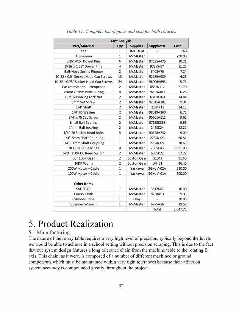
4.4 Cost Analysis We have analyzed the cost of both rotaries in a worst case scenario, as shown in the table below. The cost of the 5th axis that we are building for our sponsor will be much lower, as we are getting the motors donated from Yaskawa and the bearings at a lower price on eBay. If this were to be manufactured by someone else, they could research other sources to buy quality parts at a reduced cost. If this were to be mass produced, costs would also be reduced by purchasing in mass quantities.
32
Table 11. Complete list of parts and cost for both rotaries
5. Product Realization 5.1 Manufacturing The nature of the rotary table requires a very high level of precision, typically beyond the levels we would be able to achieve in a school setting without precision scraping. This is due to the fact that our system design features a long tolerance chain from the machine table to the rotating B axis. This chain, as it were, is composed of a number of different machined or ground components which must be maintained within very tight tolerances because their affect on system accuracy is compounded greatly throughout the project.
Part/Material Qty Supplier Supplier # Cost
Steel 1 IME Dept ‐ N/AAluminum 1 McMaster 290.00
0.25"x0.5" Dowel Pins 6 McMaster 97395A475 10.21 3/16"x 1.25" Dowel Pins 4 McMaster 97395474 11.25 Ball‐Nose Spring Plunger 2 McMaster 3408A75 7.24
10‐32 x 0.5" Socket Head Cap Screws 13 McMaster 92185A989 4.26 10‐32 x 0.75" Socket Head Cap Screws 24 McMaster 96006A693 5.71
Gasket Material ‐ Neoprene 2 McMaster 8837K112 21.70 75mm x 3mm wide O‐ring 4 McMaster 9262K409 6.26 1‐9/16"Bearing Lock Nut 2 McMaster 6343K160 14.44
3mm Set Screw 2 McMaster 92015A101 9.34 1/4" Shaft 2 McMaster 1144K11 24.15
1/4" ID Washer 2 McMaster 98019A360 6.75 3/4"x.75 Cap Screw 2 McMaster 90201A111 9.62 Small Ball Bearing 2 McMaster 57155K388 9.56 14mm Ball bearing 2 McMaster 2423K24 38.22
1/4"‐20 Socket Head bolts 8 McMaster 90128A242 9.09 1/4"‐8mm Shaft Coupling 1 McMaster 2764K123 60.54 1/4"‐14mm Shaft Coupling 1 McMaster 2764K322 78.69
7006C NSK Bearings 4 McMaster 2385K46 1,091.00 SPDT 150V DC Reed Switch 2 McMaster 6585K22 92.22
30T 16DP Gear 2 Boston Gear G1043 91.60 16DP Worm 2 Boston Gear LVHB1 46.40
200W Motor + Cable 1 Yaskawa SGMJV‐02A 550.00 100W Motor + Cable 1 Yaskawa SGMJV‐01A 500.00
Other Items
SAE 80 Oil 1 McMaster 3512K63 10.00 Emery Cloth 1 McMaster 8238A53 9.93 Cylinder Hone 1 Ebay ‐ 20.00 Spanner Wrench 1 McMaster 6975A16 19.58
Total 3,047.76
Cost Analysis

33
Table 12. Stackup Chain
System Tolerance Stackup Chain Tolerance Feature Moment Arm Material Tolerance Housing A Perpendicularity of bottom surface to bearing bore
175mm 6061AL 2 microns
Bearing set A outer race to inner race parallelism
27.5mm Tool Steel 2.5 microns
Spindle A perpendicularity of datum surface to center axis
10mm Steel 5 microns
Platter A parallelism from top to bottom plane
12.6mm Steel 2.5 microns
Adaptor plate perpendicularity from A to B mounting plane
100mm 6061AL 20 microns
Housing B Perpendicularity of bottom surface to bearing bore
100mm 6061AL 2 microns
Bearing set B outer race to inner race parallelism
27.5mm Tool Steel 2.5 microns
Spindle B perpendicularity of datum surface to center axis
10mm Steel 5 microns
Platter B parallelism from top to bottom plane
12.6mm Steel 2.5 microns
Summation 44 microns The above table illustrates the fact that even with incredible precision beyond 99 percent of most machine shops in the world, the total tolerance stackup is over 44 microns, which frankly is unacceptable for a rotary table. In order to remedy this situation, we used unique machining techniques to achieve high levels of precision in only our critical dimensions, and individually matched parts to hit our tolerances. This was time consuming and took hundreds of hours.

34
Figure 33. Housing Maching Set Up
Figure 34. Housing inspection

35
The most critical surfaces we machined were arguably the housing. It is an incredibly complex system and arguably making one of these would be worthy of a senior project in itself. The precision, fit and finish of the component are astounding. To maintain perpendicularity of the bore to the bottom surface, both of these were machined in the same machine tool, using the same endmill, in the same operation, with no less than 5 unique finishing passes. In order to maintain bore toleraces we had to push the ballscrew accuracy of the VF3 to its limits. We used in machine probing in concert with in machine gauging to precisely control our bore size, which had a tolerance of plus or minus 2 microns. The process involve finish machining the bore twice, probing the size and comparing it to the expected size, then probing a gauge block and finding the probe inaccuracy, and using this to compensate for future probing. Then the bore was finish machined again, with a 25 micron chipload, the bore was then probed to find the actual chipload, and this offset was used to make the final finishing pass in the machine.
Figure 35. Spindle Machining

36
Figure 36. Spindle Assembly
The spindly was also a critical assembly. The central spindle was machined entire in one operation, and then to hold the plus or minus tolerance of 2.5 microns on the inner bearing race mounting feature, the OD was lightly buffed to size. Following this 20 micron shims were used to ensure the length was accurate to micron levels, this allows us to preload the NSK bearings with the shown spindle nut. The whole assembly drops into the housing with only a 20-degree temperature differential thanks to the tight tolerances. Following this the top surface of the spindle was surface ground parallel to the housing bottom surface.

37
Figure 37. Perpendicularity Measurement
Ultimately the difficulties we faced in making such a complicated system were overcome, but the workload involved was considerable to say the least. This is to be accepted, there is no way around tight tolerances with such a system, and we were successful in our manufacturing endeavors.
5.2 Design Edits Our planned design described previously in this report was to use Yaskawa servomotors in conjunction with the 4th and 5th axis drive cards from Haas, both of which were donated for our project. In order for the motor to interface with the 4th and 5th axis driver cards, we were sent the exact servo motors that Haas uses on their rotaries. Because of this, the motors were much larger and heavier than what we had been planned for and so they could not be used with our design. This was determined very late in our project, so our sponsor requested that we manufacture just a fourth axis that is compatible with Yaskawa’s donated motor. In order to complete the project that our sponsors originally asked for, we decided to create a complete 5th axis that was run with stepper motors and an external controller. A G-code macro was written that calculates the position of each axis and outputs them through the serial line as text. This text line is sent to the microprocessor of our controller, an Arduino Uno, which parses the string into recognizable commands and variables. If the letter H is sent, each axis is homed, by spinning until the reed switch registers and then moving to a predetermined offset. Otherwise, each axis can be sent a direction and number of degrees and the Arduino will calculate how many steps to turn the stepper to move to the new angle.

38
Pictured below is the controller, which contains two AC to DC power supplies, a 24 Volt one for the motors, and a 12V one to power the Arduino. Pololu DRV8825 stepper drivers are used to send commands to the steppers. A MAX3223 breakout from Sparkfun is used to convert the RS232 input to TTL so that the Arduino can properly receive the text. We chose to use NEMA 23 stepper motors with 179 oz. in. of torque in order to withstand machining loads and maneuver the weight of the B-axis.
5.3 Recommendations for Future Manufacturing While we have gone through three prototypes during our senior project in order to refine the design and improve manufacturing, there are still a few changes to make in terms of machining these parts. Dimensions that have fits should be machined to nominal sizing, and then reamed for fit. Most features should be designed for a slip fit rather than an interference fit if the mating is not crucial, as it will eliminate the need to risk the part during pressing. If the feature is crucial, machine undersize, and check the dimension before re-machining to size. The accuracy of our CNC machines were not up to par for machining tolerances of fixtures and so the dimensions had to be manually accounted for by the operator. Dimensions should be checked after machining each part and before assembly. Also, it is crucial to consider flatness tolerances on the platter of the rotary, and so the spindle and the platter should be surface ground before assembly.
Figure 38. Custom stepper motor controller

39
6. Design Verification Plan 6.1 DVP&R Documentation for our design verification plan and report can be found in Appendix F. Below are testing procedures for all of the planned tests.
6.2 Vibration Testing Background Vibration testing uses a sine sweep to find the natural frequency of the rotary. Operating at the natural frequency of the rotary can cause inaccuracies in machining, and possible structural failure. Equipment
Rotary Accelerometer Signal Analyzer Blue Box Charge Amplifier Shake Table
Procedure 1. Secure the rotary table to the shake table and attach the accelerometer with a dab of wax,
as seen in the set-up figure. 2. Connect the charge amplifier to the accelerometer and channel two of the signal analyzer. 3. Preset the signal analyzer to sine sweep between 10-2000 Hz, where the input is channel
one and output is channel two. Display the Bode Diagram with a linear magnitude. 4. Connect the signal analyzer source to channel one and the input for the shake table
controller via a tee junction. 5. Turn on the hydraulic pump and follow directions posted on the shake table control
panel. 6. Press “start” on the signal analyzer to start the sine sweep and record data. 7. Trace results to find each mode of natural frequency and print the bode diagram. 8. Repeat the procedure at least three times with the housing assembled and disassembled.

40
Setup
Figure 40. Accelerometer mounting configuration on housing with components removed
Figure 41. Housing mounted to the shake table
Figure 39. Laboratory setup diagram

41
Results
This testing was completed on February 12th, 2016 with prototype 1 in the Mechanical Engineering Vibrations Laboratory. The results showed a first modal natural frequency of 380Hz and a second mode at 1200Hz. The sweep covered 10Hz to 2000Hz and was repeated 9 times with different housing configurations. The graph of the test completed with all of the parts removed from the housing can be seen below. This testing shows that aluminum may not be a viable material for our housing since the first two modal frequencies are both at values that will be reached by the spindle.
6.3 Backlash Testing Equipment
Assembled Stage Screwdriver
Procedure
1. Place assembled housing on its side with the spring plunger facing up on the housing. 2. Tighten the spring plunger towards the gear. 3. Rotate the platter to feel the backlash. 4. Continue until no noticeable play could be detected.
6.3 Tolerance Testing Background We must check finished manufactured parts with the tolerances specified on drawings.
Figure 42. Results of vibration testing completed on the housing alone.

42
Dimensions Check Equipment
Dial Caliper Micrometer set (0 – 4”) Bore gauges Optical Comparator Housing
Procedure
1. Measure all linear dimensions as mentioned in manufacturing drawings with a caliper. 2. Measure all external diameters as mentioned in manufacturing drawings with the
appropriate sized micrometer. (0” – 1”, 1” – 2”, etc.) 3. Measure all internal diameters as mentioned in manufacturing drawings by extending the
appropriately sized bore gauge, and measuring the ends of the bore gauge with a micrometer.
4. Measure difficult to reach internal dimensions using the optical comparator. Flatness Equipment
Magnetic Base Granite Table Dial indicator Housing
Procedure
1. Place Housing on a micro-flat granite table. 2. Attach dial indicator to magnetic base and lower the dial indicator onto part until the tip
is depressed. 3. Run dial indicator across the part and measure the height at 5 points along the surface. 4. Find the range of points across the surface. The value is the flatness tolerance of the part. 5. Using datums noted on drawings at MMC, see if dimensions are within tolerance.
Figure 43. Setup to measure flatness
Granite
Part
Dial Indicator

43
Run-out Equipment
Magnetic Base Dial Indicator Assembled Housing
Procedure
1. Place each stage on a flat surface. Attach the dial indicator to the magnetic base and place on flat surface.
2. Have the test dial indicator touching the part. 3. Rotate the platter while moving the indicator along the part. 4. Measure the total variation in run-out. 5. Adjust part to best eliminate run-out.
Figure 44. Setup for measuring run-out tolerance
Results The majority of our parts were within the tolerance specified for each part. Some parts had to go back to the machining process to guarantee that dimensions were met. The overall run-out on the platter of each housing was about ∅ 0.001”.

44
6.4 Efficiency Testing Equipment
Yaskawa Servo Motor Controller Data Acquisition Rotary
Procedure
1. Measure the moment of inertia for each part in motion. 2. Pick an angular acceleration within capability of the servo motor. 3. Calculate the torque required to accelerate the calculated moment of inertia. This will
require adding torques from objects spinning at different speeds.
Where, ∗ ∗ ∗
4. Write a program that starts the motor at a constant angular speed and accelerates at the rate above. Do not measure data if motor is standstill to avoid error with inrush current.
5. Perform the acceleration with the Yaskawa motor and record torque results. 6. Compare the torque measured at the motor with the torque calculated. 7. Repeat several times at different acceleration values.
Results We were not able to perform this test because the choice of motor changed many times during the last stages of build process due to certain circumstances. If there was more time allotted, we would be able to perform this test.
6.5 Gear Wear Testing Background As the rotary runs, the gears will begin to wear, so this test gives a timeline of the gear functionality. Equipment
Housing (worm and gear) Stepper motor Arduino motor controller Power source 2 C-Clamps
Procedure
1. Measure diameter of gear and worm. 2. Clamp housing onto a flat surface. 3. Put dial indicator on the magnetic base and secure to a metal surface. 4. Connect Arduino to power source. 5. Connect motor to the Arduino controller. 6. Run a random angle program.

45
7. Turn off power and disconnect everything. 8. Measure diameter of gear and worm and record the values along with how long the
system was running
Results This test was unable to be conducted because the amount of time required to run this test was not available to us at the time the rotaries were completed, especially if the longevity of the gear was predicted to be 250000 hours.
7. Conclusions and Recommendations We have created a robust design to meet the specifications of our sponsors. Our factors of safety ensure a safe mechanism to last our rated 2400 working hours. The majority of our parts are off the shelf from McMaster Carr, and assembly can performed in any basic shop. There are 7 parts to be manufactured in house for each rotary. This allows our product to be created by other schools or home machinists with access to a mill, lathe, and laser cutter. We are confident in our design and in the ability to manufacture and test it. In terms of improvements that could be made, the rotary could be better designed for assembly. Press fits should be minimized and slip fits should be chosen instead. The preload applied to the bearings were difficult to determine and so a better method needs to be devised in order to provide the appropriate preload. The design could also be more modular, so that subassemblies could be made ahead of time and then assembled together for better efficiency. Also, critical dimensions should be more carefully watched during manufacturing. There was only limited time to test the motors and the controller, and so it would be recommended to do more extensive testing to understand the system of our rotary table. Originally, we were asked to use the Yaskawa/Haas motors for our rotary table, but it would be best to use non-proprietary motors and software for troubleshooting purposes. Based off the testing we have completed so far, we would recommend looking into getting the parts in cast iron to negate vibration concerns and lower machining costs. We would also recommend exploring what it would take to modify our design to be able to machine aluminum along with wax. It would also be beneficial to create a document that has step by step instructions to manufacture this rotary.

46
References
Albert, Mark. "Discovering 30-Taper Machines." Modern Machine Shop. Modern Machine Shop, 15 Jan. 2003. Web. 15 Oct. 2015. <www.mmsonline.com/articles/discovering-30-taper-machines>.
All Industrial Tool Supply. "The Differences Between CAT, BT and HSK Tooling." All
Industrial Blog. All Industrial Tool Supply, 30 July 2013. Web. 19 Oct. 2015. <http://blog.allindustrial.com/the-differences-between-cat-bt-and-hsk-tooling/>.
Ally Tech. "Dual Lead Concept Duplex System." Allytech.com. N.p., n.d. Web. 17 Nov. 2015. Armstrong, Stephen C. Engineering and Product Development Management: The Holistic
Approach. Cambridge: Cambridge UP, 2001. Print. Arnold, Heinrich. The Recent History of the Machine Tool Industry and the Effects of
Technological Change. Siteseer.edu. University of Munich, Institute for Innovation Research and Technology Management, Nov. 2001. Web. 19 Oct. 2015. <http://citeseerx.ist.psu.edu/viewdoc/download?doi=10.1.1.119.2125&rep=rep1&type=pdf>.
Bullard, Edward P. Rotary Table Bearing. Patent 828,876. 21 Aug. 1906. Web. Cone Drive. "Servo Zero Backlash Gear Sets." Conedrive.com. N.p., n.d. Web. 17 Nov. 2015. Haas Automation. "Haas DT-1." Haas DT-1Technical Specifications (2015) Haascnc.com. Haas
Automation, Aug. 2015. Web. 14 Oct. 2015. <www.haascnc.com/mt_spec1.asp?id=DT-1&webID=DRILL_TAP_VMC#gsc.tab=0f>.
Haas Automation. "Haas OM-2A." Haas OM-2A Technical Specifications (2015) Haas.cnc.com.
Haas Automation, Aug. 2015. Web. 14 Oct. 2015. <www.haascnc.com/DOCLIB/datasheets/DS_OMseries_US.pdf>.
Haas Automation. "Haas TRT100." Haas TRT100 Technical Specifications (2015) Haascnc.com.
Haas Automation, Aug. 2015. Web. 14 Oct. 2015. <www.haascnc.com/DOCLIB/datasheets/DS_TRT100_US.pdf>.
Iwase, Yoshio, Masahiro Machida, and Yoshihiro Machida. Ball Speed Reducer and Rotary
Table Device Using the Same. Meko Seiki, Inc., assignee. Patent US 8,549,947 B2. 8 Oct. 2013. Web.
Kato, Heizaburo, Masaaki Hori, and Katsuyuki Iida. Rotary Table Apparatus. Sankyo
Seisakusho Co., assignee. Patent US 7,603,930 B2. 20 Oct. 2009. Web. Mauro, George. Anti-Backlash Mechanism for a Rotary Stage. Patent 6,016,716. 25 Jan. 2000.
Web.

47
Mitsubishi Heavy Industries. "Unparalleled Power Transmission." Feature No.170 | Mitsubishi Heavy Industries, Ltd. Global Website. Mitsubishi Heavy Industries, n.d. Web. 17 Nov. 2015.
NSK. "Super Precision Bearings." Product Catalog | NSK Americas. Web. 15 Feb. 2016. O'Neil, Stephan J. "Methods to Minimize Gear Backlash." Machinedesign.com. Machine Design,
7 Aug. 2013. Web. 17 Nov. 2015. QTC Metric Gears. "KWGDL Duplex Worms." Qtcgears.com. N.p., n.d. Web. 17 Nov. 2015. Sherman, David, and Andrew Van Cleve. "The Decision Process of Transitioning From a 3-Axis
to a 4-Axis or 5-Axis Mill Machine." Thesis. California Polytechnic State University, 2013. California Polytechnic State University, May 2013. Web. 14 Oct. 2015.
Velasquez, Thomas R., David E. Wolf, Cody J. Carothers, and Brian J. Thoma. Rotary Position
Encoder. Haas Automation, Inc, assignee. Patent US 2010/0033170 A1. 11 Feb. 2010. Web.
Yaskawa. "Rotary Servo Motors SGMJV." Sigma-5 Servo Product Catalog | Yaskawa.com.
Web. 15 Feb. 2016. Yaskawa. SigmaSelect. Computer software. Yaskawa.com. Vers. 1.0.4.4. N.p., 26 Oct. 2015.
Web. 17 Nov. 2015.

48
Appendices A: Specifications List B: Detailed Drawings C: Structured BOM D: Component Specification Sheets E: EES Formatted Calculations F: FMEA and Design Verification G: Gantt Chart H: Operator’s Manual

Appendix A
Specifications List

Number Feature Value UnitDemand
vs.Desire
Source Compliance EngineeringRisk Notes
1.1 Max Rotary Length 16 in Demand OM2 Specs Inspection Low May interfere with tool change1.2 Max Rotary Width 10 in Demand OM2 Specs Inspection Low1.3 Max Work Table Height 4 in Demand OM2 Specs Inspection Medium1.4 Max Rotary Height 10 in Demand OM2 Specs Inspection Low Cannot interfere with tool change
1.5A Work Area Diameter 5 in Desire Rotary Comparison Inspection High Max part : 5" Cylinder1.5B Work Area Diameter 3 in Demand Rotary Comparison Inspection Low Min part : 3" Cylinder1.6A Max Work Piece Height 5 in Desire Rotary Comparison Inspection High Max part : 5" Cylinder1.6B Max Work Piece Height 3 in Demand Rotary Comparison Inspection Low Min part : 3" Cylinder
2.1 Rotational Speed 30 rpm Desire Rotary Comparison Test High TRT100 goes 167rpm2.2 Tilt Speed 30 rpm Desire Rotary Comparison Test High2.3 Resolution 0.001 deg Desire Rotary Comparison Test High Same as the TRT1002.4 Axix B (Rotary) Travel 360 deg Desire Rotary Comparison Test Low Continuous rotation. Same as the TRT1002.5 Axis A (Tilt) Travel ±120 deg Desire Rotary Comparison Test Low Same as the TRT100
3.1 Max Part Weight 5 lbf Desire Rotary Comparison Test Low This is a static force on the rotary table3.2A Average Applied Load 18 lbf Demand Measured Spindle Loads Analysis Medium Calculated for soft plastics3.3 Axis A (Tilt) 6 ft-lb Demand Hand calculation Analysis Medium Direct Drive torque3.4 Axis B (Rotary) 3 ft-lb Demand Hand calculation Analysis Medium Direct Drive torque3.5 Min Natural Frequency 2000 Hz Desire Hand calculation Analysis High Assume a 4 flute endmill at 30,000 rpm3.6 Stiffness 0.001 in Desire Keep part accuracy Analysis High
4.1 AC Motors OM2 Compatible - - Demand Compatable with Haas Test Low Motors from Yaskawa
5.1 Rust and corrosion resistant - - Demand REL Environment Test Low Must function in lubricant5.2 Wax machining - - Demand Sponsor Requirement Test Medium Design to machine wax
6.1 Controlled with 5-axis software - - Demand G-code Test Low HSM 5th axis software
5. Materials
6. Signals
4. Energy
Specification SheetProject 21. 4th and 5th Rotary Stages
1. Geometry
2. Kinematics
3. Forces

Number Feature Value UnitDemand
vs.Desire
Source Compliance EngineeringRisk Notes
Specification SheetProject 21. 4th and 5th Rotary Stages
6.2 Simultaneous control with x y z - - Demand Sponsor Requirement Test Medium6.2 5th axis installation - - Demand Haas Test Low Use cards provided by Haas
7.1 Handling by trained personel - - Demand OSHA Test Low Hard point(s) for lifting. Avoid pinch points7.2 Safety Factor 2 - Demand Design safety factor Analysis Low Minimum factor of safety
9.1 Manufactured Part Tolerance ±0.005 in Desire 0.01in Tolerance Inspection High9.2 Part size limitation 5 in3 Demand Consumer Demand Inspection Medium Cylinder9.3 Machining in house - - Desire Cost Inspection Medium Mustang 60 / IME Dept CNC
10.1 Instructions - - Demand Sponsor Requirement Inspection Low Open source documentation10.2 Compatible with T-slots - - Demand Sponsor Requirement Inspection Low Bolts to work table securely
11.1 Maximum Weight 40 lbs Desire OM2 Specs + Ergonomics Inspection Medium To be lifted by one person
12.1 Workholder Bolt Pattern - - Demand Rotary Comparison Inspection Low To be used with industry work holders 12.2 Machine lifetime 2400 hours Desire Estimate Analysis High 3 years, 20 hrs/week, 40 weeks/yr12.3 Simultaneous machining 5 axes Demand Sponsor Requirement Test Medium13.4 Homing - - Demand - Test Medium Must home for each use13.5 Operated by trained personel - - Demand - Test Low User must know how to use CNC13.6 Tramming with Square Sides - - Demand Rotary installation Inspection Low In order to center fixture
14.1 Standard Tools/Fluids - - Demand CNC Maintenance Inspection Low Specialty tools and materials not required
15.1 Force Testing Jan. month Desire Senior Project Timeline Test Low Date: Mid January15.2 Functionality Testing Jan. month Desire Senior Project Timeline Test Low Make a 3" wax impeller
15.1 Max Final Production Cost 25,000 USD Demand OM2 Cost Inspection Medium Affordable alternative16. Time Schedule
7. Safety
10. Manufacturing / Production
11. Assembly
12. Transportation
13. Usage / Operation
14. Maintainance
15. Quality Control
15. Cost

Number Feature Value UnitDemand
vs.Desire
Source Compliance EngineeringRisk Notes
Specification SheetProject 21. 4th and 5th Rotary Stages
16.1 Prototype Jan. month Desire Senior Project Timeline Inspection Low Delivery Date: January16.2 Final Product May month Desire Senior Project Timeline Inspection Low Delivery Date: May

Appendix B
Assembly With Bill of Materials
Housing Detailed Drawing
Shaft Detailed Drawing
Platter Detailed Drawing
Cover Detailed Drawing
Preload Detailed Drawing
Worm Gear Detailed Drawing

ITEM NO. PART NUMBER DESCRIPTION QTY.1 Shaft 12 6343K16 Shaft Collar 13 98019A360 Mil. Spec. Washers 14 Platter 15 97395A475 Dowel Pins 26 92185A989 Stainless Steel Socket Head Cap
Screws 11
7 HSG 18 9114m7lmEUL 19 90201A111 Extreme-Strength Steel Cap Screws 110 91XPTvqQy3L 111 Cover 112 9262K409 Multipurpose O-Rings 213 TopGasket 1
14 57155K388 Double Shielded with Extended Inner Ring 1
15 Preload 116 97395A474 Dowel Pins 217 3408A21 Spring plungers 118 2385K46 219 65985K22 Reed Switch 120 65985K22 Reed Switch 121 6061K411 Shaft 122 BottomGasket 123 Nema 23 Stepper 124 Cap 125 6138K54 Ball Bearings 126 6099K21 Shaft Coupling 127 92185A991 SS Socket Head Cap Screws 10
4
A
123
B B
A
2 134
PARTS LIST 5TH AXIS
SHEET 1 OF 1
REVDWG. NO.
BSIZE
TITLE:

.787 1.537
4 X R.126
1.772
.591
2.953
.250 .300
4 X 10-32 UNF .89.001 A
B
4.331
4 X 10-32 UNF .400D
D
.005
.005
5.315
5.315
4 X R.236
10 X 10-32 .394
1.969
2.165
2.657
2.657 4.724
.001
.001 A
A
C
1/4-20 UNC THRU
.159 THRU SURFACE .330 .200
2 X .186 THRU
1.063 1.289
2.788
SECTION D-D
R1.308 4 X 10-32 UNF .380
.550 THRU.624 .279.635 .118
1.575 .079 1.189
1.408
4
A
123
B B
A
2 134
6061 ALSCALE: 2:3
UNITS:IN
MATERIAL:
BSIZE
TITLE:
CAL POLY SLOME DEPARTMENT
NOTESNON-DIMENSIONED FEATURES1.ARE BASIC AND CONTROLLED BY THE MODELGENERAL PROFILE TOLERANCE2.APPLIES TO ALL BASIC DIMENSIONSPART TO BE DEBURRED AND3.CLEANED OF ALL RESIDUEHOLES ARE SPACED EVENLY4.RADIALLY AROUND THE SPECIFIED RADIUS
HSG B-AXIS

1.1811+-.0000.0002
.2500
1.0231±.0003
.5000
.3500
60.00°±.01° Threaded:.969"-32
.0001 A.0005 A
B
A
.8800
A
A
6x 10-32
6x 10-32
.004 M A B M
.3000
.60001/4-20 Tapped Hole
SECTION A-ASCALE 2 : 1
SHAFT
4
A
123
B B
A
2 134
1XXX STEELSCALE: 2:1 WEIGHT:
UNITS:IN
MATERIAL:
BSIZE
TITLE:
CAL POLY SLOME DEPARTMENT
NOTESNON-DIMENSIONED FEATURES 1.ARE BASIC AND CONTROLLED BY THE MODELGENERAL PROFILE TOLERANCE 2.APPLIES TO ALL BASIC DIMENSIONSPART TO BE DEBURRED AND 3.CLEANED OF ALL RESIDUESCRAPED OR GROUND 4.SURFACES REQURED ON A DATUMSEMERY CLOTH TO CORRECT A 5.DIAMETER IS ALLOWABLE

.500
.071
.071
POCKET FOR NEOMIDIUM MAGNET 8.5MM 5MM
A
.200 THRU.330 .200
.500 .150
3.937(100MM)
.8800
2.5000
3.2670
3.3520
15°
6 X 5/16-18 TAPPED HOLE .400
6 X 1/4-20 TAPPED HOLE .400
6 X 10-32 TAPPED HOLE .400 PLATTER
.001 A
.001
4
A
123
B B
A
2 134
TOOL STEELSCALE: 1:1 WEIGHT:
UNITS:IN
MATERIAL:
BSIZE
TITLE:
CAL POLY SLOME DEPARTMENT
NOTESNON-DIMENSIONED FEATURES1.ARE BASIC AND CONTROLLED BY THE MODELGENERAL PROFILE TOLERANCE2.APPLIES TO ALL BASIC DIMENSIONSPART TO BE DEBURRED AND3.CLEANED OF ALL RESIDUESCRAPED OR GROUND4.SURFACES REQURED ON ALL DATUMSHOLES ARE SPACED EQUALLY5.RADIALLY ON EACH SPECIFIED DIAMETER
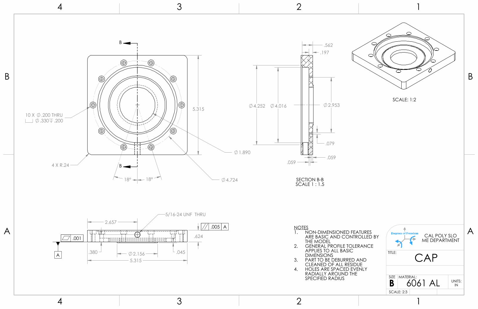
.624
.045
5.315
.380
5/16-24 UNF THRU 2.657
2.156 A
5.315
4 X R.24
10 X .200 THRU.330 .200
1.890
4.724 18° 18°
B
B
.005 A
.001
SCALE: 1:2
.197 .562
.059 .059
.079
2.953 4.252 4.016
SECTION B-BSCALE 1 : 1.5
NOTESNON-DIMENSIONED FEATURES1.ARE BASIC AND CONTROLLED BY THE MODELGENERAL PROFILE TOLERANCE2.APPLIES TO ALL BASIC DIMENSIONSPART TO BE DEBURRED AND3.CLEANED OF ALL RESIDUEHOLES ARE SPACED EVENLY4.RADIALLY AROUND THE SPECIFIED RADIUS
4
A
123
B B
A
2 134
6061 ALSCALE: 2:3
UNITS:IN
MATERIAL:
BSIZE
TITLE:
CAL POLY SLOME DEPARTMENT
CAP

.566 THRU.625 .250
1.03
.600 .900
.300 2 X .190 .305
.150
SCALE: 2:1
4
A
123
B B
A
2 134
6061 ALSCALE: 2:3
UNITS:IN
MATERIAL:
BSIZE
TITLE:
CAL POLY SLOME DEPARTMENT
NOTESNON-DIMENSIONED FEATURES1.ARE BASIC AND CONTROLLED BY THE MODELGENERAL PROFILE TOLERANCE2.APPLIES TO ALL BASIC DIMENSIONSPART TO BE DEBURRED AND3.CLEANED OF ALL RESIDUE
SPRING FORCER

.686
.312
.763 1.940
(MINOR DIAMETER)
CC
.313
.294.653
60.0°
SECTION C-C
NOTETHIS IS A MODIFIED WORM GEAR FROM MCMASTER CARR, PART 9114M7IMEUL.
4
A
123
B B
A
2 134
BRONZESCALE: 2:1
UNITS:IN
MATERIAL:
BSIZE
TITLE:
CAL POLY SLOME DEPARTMENT
WORM GEAR

Appendix C
Structured Bill of Materials
Cost Bill of Materials

L1 L2 L3 L4 L51 1 Rotary Table Overall 10000
1 1 Axis B One axis of Rotation 110001 1 Housing Body Sub‐Assembly Base of one rotary axis ‐ ‐ ‐
1 1 Housing Body Holds shaft and gear train assem. 11110 MAKE ‐2 1 14mm Ball bearing Locates worm shaft ‐ McMaster 2423K243 2 0.25"x0.5" Dowel Pins Locates attachment plate onto housing ‐ McMaster 97395A475
2 1 Platter Sub‐Assembly Holds working part ‐ ‐ ‐1 1 Platter Holds working part 11210 MAKE ‐2 6 10‐32 x 0.5" Socket Head Cap Screws Tightens platter onto cap ‐ McMaster 92185A989
3 1 Cap Sub‐Assembly Retains bearing race ‐ ‐ ‐1 1 Cap Retains bearing race 11310 MAKE ‐2 1 Gasket Prevents material from entering housing 11320 McMaster 8837K1123 10 10‐32 x 0.75" Socket Head Cap Screws Tightens cap onto housing ‐ McMaster 96006A6934 2 75mm x 3mm wide O‐ring Prevents oil from entering housing ‐ McMaster 9262K4095 1 0.25" x 0.5" Dowel Pin Locates center of cap to platter ‐ McMaster 97395A4756 1 SPDT 150V DC Reed Switch For homing ‐ McMaster 6585K22
4 Shaft Sub‐Assembly Allows work piece to rotate ‐ ‐ ‐1 1 Shaft Holds bearings and platter 11410 MAKE ‐2 2 7006C NSK Bearings Allows platter to rotate in housing ‐ Mcmaster 2385K463 1 1‐9/16"Bearing Lock Nut Preloads bearings ‐ McMaster 6343K160
5 1 Gear Train Sub‐Assembly Turns motor rotation into mech power ‐1 1 30T 16DP Gear Rotates shaft, gives 30:1 reduction ‐ Boston Gear G10432 1 16DP Worm Contacts 30T gear ‐ Boston Gear LVHB13 1 3mm Set Screw Holds worm in place ‐ McMaster 92015A1014 1 1/4" Shaft Rotates worm, attaches to motor ‐ McMaster 1144K115 1 1/4" ID Washer Evens out force over gear, prevents loosening ‐ McMaster 98019A3606 1 3/4"x.75 Cap Screw Attaches 30T gear to shaft ‐ McMaster 90201A1117 1 Gear Preload Sub‐Assembly Preloads gears to prevent major backlash ‐ ‐ ‐
1 1 Gear Preload Mechanism Pushes worm against gear 11571 MAKE ‐2 1 1/4" Ball Bearing Locates worm shaft ‐ McMaster 57155K3883 1 Ball‐Nose Spring Plunger Constant force engagement on worm ‐ McMaster 3408A754 2 3/16" x 1.25" Dowel Pins Locates Gear preload mechanism McMaster 97395474
6 1 Motor Assembly Provides power to table ‐1 1 100W Motor Rotates worm shaft ‐ Yaskawa SGMJV‐01A2 1 1/4"‐8mm Shaft Coupling Connects motor shaft to worm shaft ‐ McMaster 2764K1233 1 Motor Cable Powers motor ‐ Yaskawa ‐
2 1 Axis A Rotates 4th Axis 120001 1 Housing Body Sub‐Assembly Base of one rotary axis ‐ ‐ ‐
1 1 Housing Body Holds shaft and gear train assem. 11110 MAKE ‐2 1 14mm Ball bearing Locates worm shaft ‐ McMaster 2423K24
2 1 Platter Sub‐Assembly Holds working part ‐ ‐ ‐1 1 Platter Holds working part 11210 MAKE ‐2 6 10‐32 x 0.5" Socket Head Cap Screws Tightens platter onto cap ‐ McMaster 92185A9893 2 0.25"x0.5" Dowel Pins Locates attachment plate onto Axis ‐ McMaster 97395A475
3 1 Cap Sub‐Assembly Retains bearing race ‐ ‐ ‐1 1 Cap Retains bearing race 11310 MAKE ‐2 1 Gasket Prevents material from entering housing ‐ McMaster 8837K1123 10 10‐32 x 0.75" Socket Head Cap Screws Tightens cap onto housing ‐ McMaster 96006A6934 2 75mm x 3mm wide O‐ring Prevents oil from entering housing ‐ McMaster 9262K4095 1 0.25" x 0.5" Dowel Pin Locates center of cap to platter ‐ McMaster 97395A475
4 Shaft Sub‐Assembly Allows work piece to rotate ‐ ‐ ‐1 1 Shaft Holds bearings and platter ‐ MAKE ‐2 2 7006C NSK Bearings Allows platter to rotate in housing ‐ McMaster 2385K463 1 1‐9/16"Bearing Lock Nut Preloads bearings ‐ McMaster 6343K160
5 1 Gear Train Sub‐Assembly Turns motor rotation into mech power ‐1 1 30T 16DP Gear Rotates shaft, gives 30:1 reduction ‐ Boston Gear G10432 1 16DP Worm Contacts 30T gear ‐ Boston Gear LVHB13 1 3mm Set Screw Holds worm in place ‐ McMaster 92015A1014 1 1/4" Shaft Rotates worm, attaches to motor 11540 McMaster 1144K115 1 1/4" ID Washer Evens out force over gear, prevents loosening ‐ McMaster 98019A3606 1 3/4"x.75 Cap Screw Attaches 30T gear to shaft ‐ McMaster 90201A1117 1 Gear Preload Sub‐Assembly Preloads gears to prevent major backlash ‐ ‐ ‐
1 1 Gear Preload Mechanism Pushes worm against gear 11571 MAKE ‐2 1 1/4" Ball Bearing Locates worm shaft ‐ McMaster 57155K3883 1 Ball‐Nose Spring Plunger Constant force engagement on worm ‐ McMaster 3408A754 2 3/16" x 1.25" Dowel Pins Locates Gear preload mechanism McMaster 97395474
6 1 Motor Assembly Provides power to table ‐
PART FUNCTION DRAWING # SUPPLIER SUPPLIER #QTYPART #
Structured Bill of Materials

1 1 200W Motor Rotates worm shaft ‐ Yaskawa SGMJV‐02A2 1 1/4"‐14mm Shaft Coupling Connects motor shaft to worm shaft ‐ McMaster 2764K3223 1 Motor Cable Powers motor ‐ Yaskawa ‐
3 1 Attachment Plate Sub‐Assembly Combines axes ‐ ‐ ‐1 1 Fixture Plate Allows Axis B to attach to A 13100 MAKE ‐2 8 1/4"‐20 Socket Head bolts Attaches fixture plate to both axes ‐ McMaster 90128A242
4 1 Gear Pocket End Cap Sub‐Assembly Seals opening in housing ‐ ‐ ‐1 1 Gear Pocket Gasket Prevents oil from leaking out of housing 14100 McMaster 8837K1122 1 Gear Pocket Lid Closes opening in housing 14200 ‐ ‐3 4 10‐32 x 0.75" Socket Head Cap Screws Tightens cap onto housing ‐ McMaster 96006A693

Part/Material Qty Supplier Supplier # Cost Steel 1 IME Dept - N/A
7006C NSK Bearings 4 McMaster 2385K46 1,091.00 8mm Ball bearing 1 McMaster 2423K21 15.15
14mm Ball bearing 1 McMaster 2423K24 19.11 1/4"-8mm Shaft Coupling 1 McMaster 2764K123 60.54
1/4"-14mm Shaft Coupling 1 McMaster 2764K322 78.69 Ball-Nose Spring Plunger 2 McMaster 3408A75 7.24
1/4" Ball Bearing 2 McMaster 57155K388 9.56 1/4" Shaft 4 McMaster 6061K411 4.20
1-9/16"Bearing Lock Nut 2 McMaster 6343K160 14.44 SPDT 150V DC Reed Switch 2 McMaster 6585K22 92.22 Gasket Material - Neoprene 2 McMaster 8837K112 21.70 1/4"-20 Socket Head bolts 8 McMaster 90128A242 9.09
1/4"-20x.75 Cap Screw 2 McMaster 90201A111 9.62 3mm Set Screw 2 McMaster 92015A101 9.34
10-32 x 0.5" Socket Head Cap Screws 13 McMaster 92185A989 4.26 50mm x 2mm O-ring 2 McMaster 9262K208 9.31
75mm x 2mm wide O-ring 4 McMaster 9262K409 6.26 10-32 x 0.75" Socket Head Cap Screws 24 McMaster 96006A693 5.71
3/16" X 1 1/8" Dowel Pins 2 McMaster 97395A474 11.25 0.25"x0.5" Dowel Pins 6 McMaster 97395A475 10.21
1/4" ID Washer 2 McMaster 98019A360 6.75 30T 16DP Gear 2 Boston Gear G1043 91.60
16DP Worm 2 Boston Gear LVHB1 46.40 100W Motor + Cable 1 Yaskawa SGMJV-01A 500.00 200W Motor + Cable 1 Yaskawa SGMJV-02A 550.00
Aluminum 1 McMaster 290.00
Other ItemsEmery Cloth 1 McMaster 8238A53 9.93
Cylinder Hone 1 Ebay - 20.00 Spanner Wrench 1 McMaster 6975A16 19.58
0.001" Shim Stock 4 McMaster 97022A151 30.32 Total 3,053.48
Actual 2,003.48
Cost Analysis

Appendix D
¾ in Cap Screw
3mm Set Screw
10-32x0.5” Cap Screw
10-32x0.75” Cap Screw
Bearing Lock Nut
Dowel Pin
Gasket Rubber
Linear Ball Bearing
Platter O-Ring
Washer
16DP Worm
30 Tooth, 16DP Gear
Worm and Gear Combined
Worm Shaft
¼ in Ball Bearing
NSK Angular Contact Ball Bearings
¼ in to 14mm Shaft Coupling
¼ in to 8mm Shaft Coupling
Ball-Nose Spring Plunger
¼”-20x0.25” Socket Head Cap Screw
3/16”x1.75” Dowel Pin
SPDT 150V DC Reed Switch
14mm Ball Bearing

2/15/2016 McMasterCarr ExtremeStrength Grade 9 Steel Cap Screw, 1/4"20 Fully Threaded, 3/4" Long, ZincPlated
http://www.mcmaster.com/#90201a111/=1152aw0 1/2
ExtremeStrength Grade 9 Steel Cap Screw1/4"20 Fully Threaded, 3/4" Long, ZincPlated
In stock$9.62 per pack of 25
90201A111
Material Steel
Grade 9
Finish Zinc YellowChromate Plated
Thread Size 1/4"20
Head Width 7/16"
Head Height 3/16"
Screw Size 1/4" (0.250")
Length 3/4"
Thread Length Full
RoHS Not Compliant
These are our strongest cap screws. They are made from alloy steel. Length is measured from underthe head.
Inch screws have a hefty head that’s 20% taller than a standard cap screw head and a minimumtensile strength of 180,000 psi. They are zinc yellowchromate plated for rust resistance and havenine radial markings to indicate Grade 9. They have a minimum Rockwell hardness of C38 and aClass 2A thread fit. Use with Grade 9 nuts and washers.
(562) 6925911(562) 6952323 (fax)[email protected] 75930

2/15/2016 McMasterCarr ExtremeStrength Grade 9 Steel Cap Screw, 1/4"20 Fully Threaded, 3/4" Long, ZincPlated
http://www.mcmaster.com/#90201a111/=1152aw0 2/2
The information in this 3D model is provided for reference only.

2/15/2016 McMasterCarr 188 Stainless Steel Cup Point Set Screw, M3 Size, 3mm Long, 0.5mm Pitch
http://www.mcmaster.com/#92015a101/=1152ago 1/2
188 Stainless Steel Cup Point Set ScrewM3 Size, 3mm Long, 0.5mm Pitch
In stock$9.34 per pack of 100
92015A101
Point Style Cup
Material 188 Stainless Steel
Thread Size M3
Pitch 0.5 mm
Length 3 mm
Drive Style Hex Socket
Hex Size 1.5 mm
RoHS Compliant
Screws have a hex socket. Length listed is the overall length.
Metric screws meet DIN 916/ISO 4029. Stainless steel screws have a Class 6g threadfit.
(562) 6925911(562) 6952323 (fax)[email protected] 75930

2/15/2016 McMasterCarr 188 Stainless Steel Cup Point Set Screw, M3 Size, 3mm Long, 0.5mm Pitch
http://www.mcmaster.com/#92015a101/=1152ago 2/2
The information in this 3D model is provided for reference only.

2/15/2016 McMasterCarr Type 316 Stainless Steel Socket Head Cap Screw, 1032 Thread, 1/2" Length
http://www.mcmaster.com/#92185a989/=11528lt 1/2
Type 316 Stainless Steel Socket Head Cap Screw1032 Thread, 1/2" Length
In stock$4.26 per pack of 25
92185A989
Thread Size 1032
Length 1/2"
Thread Length Full
Additional Specifications Type 316 Stainless Steel
RoHS Compliant
Choose stainless steel screws when you need corrosion resistance. Length is measured fromunder the head.
Inch screws have a Class 3A thread fit, a minimum tensile strength of 70,000 psi, and a minimumRockwell hardness of B70.
(562) 6925911(562) 6952323 (fax)[email protected] 75930

2/15/2016 McMasterCarr Type 316 Stainless Steel Socket Head Cap Screw, 1032 Thread, 1/2" Length
http://www.mcmaster.com/#92185a989/=11528lt 2/2
The information in this 3D model is provided for reference only.

2/15/2016 McMasterCarr Black Oxide 188 Stainless Steel Socket Head Cap Screw, 1032 Thread, 3/4" Length
http://www.mcmaster.com/#96006a693/=11529i1 1/2
Black Oxide 188 Stainless Steel Socket Head Cap Screw1032 Thread, 3/4" Length
In stock$5.71 per pack of 25
96006A693
Thread Size 1032
Length 3/4"
Thread Length Full
Additional Specifications BlackOxide 188 Stainless Steel
RoHS Compliant
Choose stainless steel screws when you need corrosion resistance. Length is measured from underthe head.
Inch screws have a Class 3A thread fit, a minimum tensile strength of 70,000 psi, and a minimumRockwell hardness of B70.
Black Oxide—Screws have a matteblack finish.
(562) 6925911(562) 6952323 (fax)[email protected] 75930

2/15/2016 McMasterCarr Black Oxide 188 Stainless Steel Socket Head Cap Screw, 1032 Thread, 3/4" Length
http://www.mcmaster.com/#96006a693/=11529i1 2/2
The information in this 3D model is provided for reference only.

2/15/2016 McMasterCarr Bearing Locknut Shaft Collar, with 0.969"32 Thread, Steel
http://www.mcmaster.com/#6343k16/=1152a66 1/2
Bearing Locknut Shaft Collarwith 0.969"32 Thread, Steel
In stock$7.22 Each6343K16
Material Steel
Inch/Metric Inch
Thread Size 0.969"32
OD 1 9/16"
Width 15/32"
In addition to fine threads, which provide close engagement on your shaft, collars have a flexible lining thathugs your shaft to lock your bearing in place. They help eliminate the looseness commonly associatedwith locknuts that use keyways and lock washers, which are not required with these collars. They alsoallow precise positioning and better squareness of the retaining ring to the bearing face to hold bearings inplace. All collars work with SAE, ABEC, and ANSI/ABMA standard products.
(562) 6925911(562) 6952323 (fax)[email protected] 75930

2/15/2016 McMasterCarr Bearing Locknut Shaft Collar, with 0.969"32 Thread, Steel
http://www.mcmaster.com/#6343k16/=1152a66 2/2
The information in this 3D model is provided for reference only.

2/15/2016 McMasterCarr Corrosion Resistant Dowel Pin, Type 316 Stainless Steel, 1/4" Diameter, 1/2" Length
http://www.mcmaster.com/#97395a475/=1152877 1/2
Corrosion Resistant Dowel PinType 316 Stainless Steel, 1/4" Diameter, 1/2" Length
In stock$10.21 per pack of 10
97395A475
Length 1/2"
Additional Specifications Type 316 Stainless Steel1/4" Dia.
RoHS Compliant
Pins are commonly used as pivots, hinges, shafts, jigs, and fixtures to locate orhold parts. They are precision ground (unless noted) for more accuratealignment, and slightly oversized for a tight fit. To aid insertion, ends arebeveled or rounded (unless noted). For a tight fit, your hole should be equal to orslightly smaller than the diameter shown. Breaking strength and Rockwellhardness are not rated (unless noted). Materials that have a breaking strengthare measured as double shear, which is the force required to break a pin intothree pieces.
Type 316 Stainless Steel—Our most corrosion resistant dowel pins. May bemagnetic. Diameter tolerance is +0.0002".
Not rated for breaking strength.
(562) 6925911(562) 6952323 (fax)[email protected] 75930

2/15/2016 McMasterCarr Corrosion Resistant Dowel Pin, Type 316 Stainless Steel, 1/4" Diameter, 1/2" Length
http://www.mcmaster.com/#97395a475/=1152877 2/2
The information in this 3D model is provided for reference only.

2/15/2016 McMasterCarr Nonmarking Neoprene Rubber, 1/16" Thick, 12" x 12", 50 Durometer, Black
http://www.mcmaster.com/#8837k112/=115292c 1/1
Nonmarking Neoprene Rubber1/16" Thick, 12" x 12", 50 Durometer, Black
In stock$10.85 Each8837K112
Shape Sheet
Material Neoprene
Texture Smooth
Thickness 1/16"
Thickness Tolerance 0.016" to +0.016"
Width 12"
Width Tolerance +0.500"
Length 12"
Length Tolerance +0.5"
Backing Type Plain
For Use Outdoors No
Temperature Range 30° to 220° F
Tensile Strength 1,200 psi
Color Black
Specifications Met ASTM D2000 BC
Durometer 50A (Medium)
Durometer Tolerance 5 to +5
RoHS Compliant
While other black rubber can leave a mark after use, these specially formulatedneoprene sheets leave no evidence behind. Neoprene is also known as chloroprene.It has good oil and abrasion resistance.
(562) 6925911(562) 6952323 (fax)[email protected] 75930

2/15/2016 McMasterCarr Fixed Alignment HighTemperature Linear Ball Bearing, Steel Bearing with Steel Ball, for 1/4" Shaft Diameter
http://www.mcmaster.com/#6064k51/=115224f 1/2
Fixed Alignment HighTemperature Linear Ball BearingSteel Bearing with Steel Ball, for 1/4" Shaft Diameter
In stock$23.88 Each
6064K51
Linear Bearing Component Bearing
For Shaft Type Round
Bearing Type Ball
Alignment Style Fixed
With Retaining Ring Grooves Yes
For Shaft Diameter 1/4"
ID 0.250"
ID Tolerance 0.0005" to 0"
Overall Length 3/4"
For Housing ID 0.500" 0.501"
OD 1/2"
OD Tolerance 0" to 0.0005"
Retaining Ring Grooves CentertoCenter
0.52"
With End Seals No
MaterialBearing SteelBall Steel
Dynamic Load Capacity 15 lbs.
Static Load Capacity Not Rated
Dynamic Load Capacity atMaximum Temperature
15 lbs. @ 500° F
Lubrication Required
Minimum Temperature Not Rated
Maximum Temperature 500° F
For Shaft Material Steel, Stainless Steel
For Minimum Shaft HardnessSteel Rockwell C56Stainless Steel Rockwell C56
Related Product External Retaining Rings
The choice for lowfriction motion in hightemperature environments. Bearingsare for use with round endsupported shafts and have a fixedalignment designfor applications where shaft misalignment is unlikely. To install, slide bearingsinto a housing (not included) and secure with two retaining rings (soldindividually).
(562) 6925911(562) 6952323 (fax)[email protected] 75930
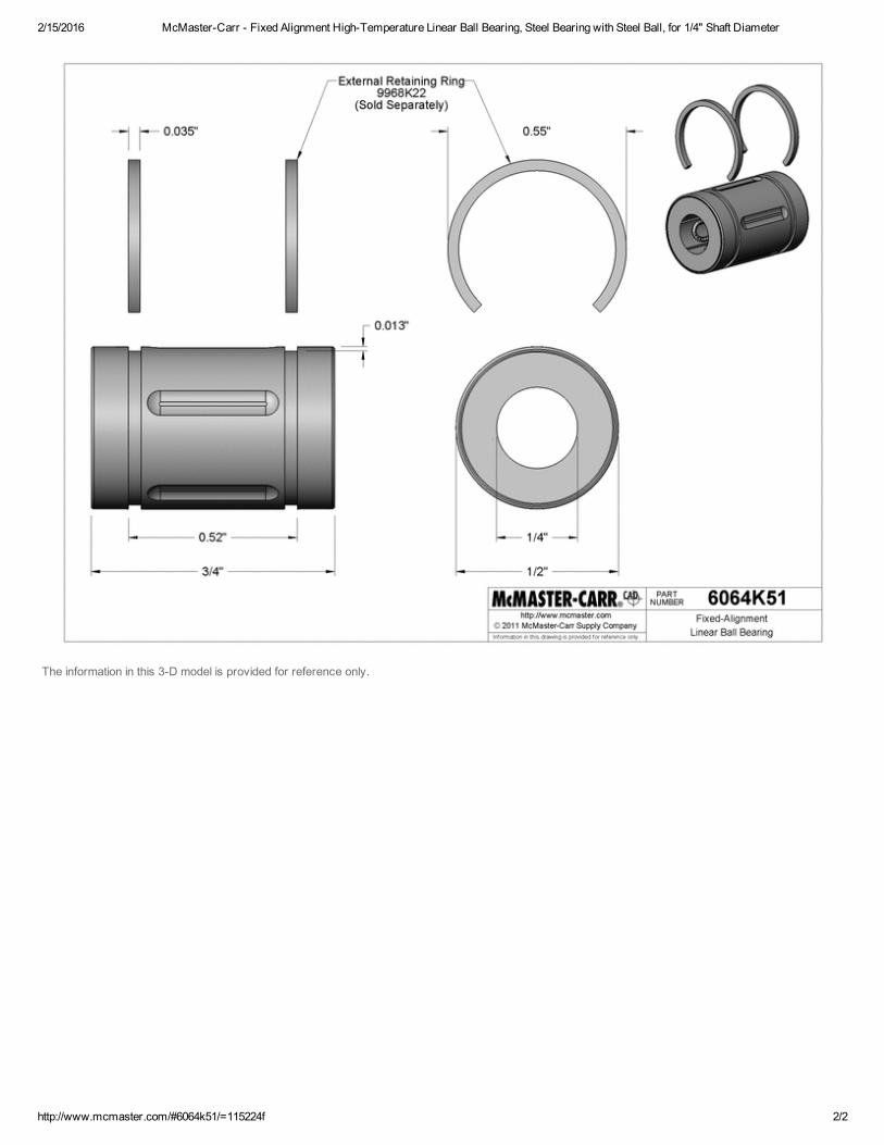
2/15/2016 McMasterCarr Fixed Alignment HighTemperature Linear Ball Bearing, Steel Bearing with Steel Ball, for 1/4" Shaft Diameter
http://www.mcmaster.com/#6064k51/=115224f 2/2
The information in this 3D model is provided for reference only.

2/15/2016 McMasterCarr Multipurpose ORing, OilResistant BunaN, 2mm Wide, 75mm ID
http://www.mcmaster.com/#9262k409/=11529tl 1/2
(562) 6925911(562) 6952323 (fax)[email protected] 75930

2/15/2016 McMasterCarr Multipurpose ORing, OilResistant BunaN, 2mm Wide, 75mm ID
http://www.mcmaster.com/#9262k409/=11529tl 2/2
The information in this 3D model is provided for reference only.

2/15/2016 McMasterCarr Mil. Spec. 300 Series Stainless Steel Flat Washer, Passivated, 1/4" Screw Size, MS/NASM15795811
http://www.mcmaster.com/#98019a360/=1152aqd 1/2
Mil. Spec. 300 Series Stainless Steel Flat WasherPassivated, 1/4" Screw Size, MS/NASM15795811
In stock$6.75 per pack of 25
98019A360
Material 300 Series Passivated Stainless Steel
Screw Size 1/4"
Specifications Met MS 15795/NASM 15795
Dash No. 811
ID 0.312"
OD 0.734"
ThicknessMinimum 0.051"Maximum 0.080"
RoHS Compliant
Washers meet strict military standards to ensure performance and reliability.
(562) 6925911(562) 6952323 (fax)[email protected] 75930

2/15/2016 McMasterCarr Mil. Spec. 300 Series Stainless Steel Flat Washer, Passivated, 1/4" Screw Size, MS/NASM15795811
http://www.mcmaster.com/#98019a360/=1152aqd 2/2
The information in this 3D model is provided for reference only.

0.250
0.625
FRONT
1.000
0.438
1.248
0.095
SIDE(BREAKOUT)
Boston Gear LVHB1 Worm Gear, 14.5 Degree Pressure Angle, 0.250" Bore, 16 Pitch, .625 PD, RH
BRAND :
REFERENCE ONLY# INFORMATION IN THIS DRAWING IS PROVIDED FOR
DIMENSIONS ARE IN INCHES# UNLESS OTHERWISE SPECIFIED Amazon Supply, An Amazon Company
ASIN :ITEM NAME:Steel
Boston Gear
B004N6356I
B004N6356IMATERIAL :
http://www.amazonsupply.com
supply

0.313
1.875
FRONT
0.312
0.76
0.686
SIDE(BREAKOUT)
Boston Gear G1043 Worm Gear, Web, 14.5 PA Pressure Angle, 0.313" Bore, 30:1 Ratio, 30 TEETH, RH
BRAND :
REFERENCE ONLY# INFORMATION IN THIS DRAWING IS PROVIDED FOR
DIMENSIONS ARE IN INCHES# UNLESS OTHERWISE SPECIFIED Amazon Supply, An Amazon Company
ASIN :ITEM NAME:Bronze
Boston Gear
B004N84ZZQ
B004N84ZZQMATERIAL :
http://www.amazonsupply.com
supply

All worms have .0938 drilled hole in hub.Hxxx worms have polished threads.Gxxx worms have ground and polished threads.
ALL DIMENSIONS IN INCHESORDER BY CATALOG NUMBER OR ITEM CODE
FACE = .313"16 WORM *CENTER LINE WORM TODIAMETRAL PITCH GEARS FLUSH END = .156"
StyleNo. Hub See SINGLE Thread DOUBLE Thread QUAD Threadof Pitch Page Catalog Item Catalog Item Catalog Item
Teeth Dia. Bore Dia. Proj. 150 Number Code Number Code Number Code
BRONZE
20 1.250 .250 .62 .31 A G1042 13612 D1142 13700 Q1342 1353630 1.875 .3125 .75 .38 B G1043 13614 D1143 13702 Q1343 1353840 2.500 C G1044 13616 D1144 13704 Q1344 1354050 3.125 G1045 13618 D1145 13706 Q1345 1354260 3.750 .375 .88 .44 D G1048 13620 D1148 13708 Q1348 1354480 5.000 G1046 13622 – – Q1346 13546100 6.250 1.00 .50 G1047 13624 – – – –
CAST IRON
20 1.250 .250 .62 .31 A CG1042 63506 CD1142 63513 CQ1342 6351830 1.875 .3125 .75 .38 B CG1043 63507 CD1143 63514 CQ1343 6351940 2.500 CG1044 63508 CD1144 63515 CQ1344 6352050 3.125 CG1045 63509 CD1145 63516 CQ1345 6352160 3.750 .375 .88 .44 C CG1048 63510 CD1148 63517 CQ1348 6352280 5.000 CG1046 63511 – – CQ1346 63523100 6.250 1.00 .50 CG1047 63512 – – – –
RATIO = Gear Teeth ÷ Worm Threads
All Worms and Worm Gears stocked RIGHT HAND ONLY.
16 WORMS FOR ABOVE GEARSDIAMETRAL PITCH
Hub SINGLE Thread DOUBLE Thread QUAD ThreadPitch Catalog Item Catalog Item Catalog ItemDia. Face Bore Dia. Proj. Number Code Number Code Number Code
UNHARDENED – STEEL
.625 1.00 .250 .44 .25 LVHB-1 12926 DVH-1 12862 QVH-1 12940HARDENED – STEEL
.625 1.00 .3125 .44 .25 HLVH-1 13032 HDVH-1 13004 HQVH-1 13058GLVH-1 12958 GDVH-1 12950 GQVH-1 13046
WORM LEAD and LEAD ANGLE
SINGLE DOUBLE QUAD
LEAD .1963" .3927" .7854"LEAD 5°43´ 11°19´ 21°48´ANGLE
STANDARD TOLERANCES
DIMENSION TOLERANCE
BORE All ±.0005
FACE
PITCHDIA.
HUBDIA.BORE
HUBPROJ.
*
FACE
PITCHDIA.
HUBDIA.
BORE
HUBPROJ.
16 DIAMETRAL PITCH PRESSURE ANGLE – SINGLE THREAD 141/2°BRONZE AND CAST IRON WORM GEARS DOUBLE THREAD 141/2°STEEL WORMS – UNHARDENED AND HARDENED QUAD THREAD 20°
WORMS AND WORM GEARS
®
Gear Catalog 77

2/15/2016 McMasterCarr Hardened Precision Shafts with Machinable Ends, Annealed Both Ends, 1/4" Diameter, 10" Length
http://www.mcmaster.com/#1144k11/=1152noe 1/2
Hardened Precision Shafts with Machinable EndsAnnealed Both Ends, 1/4" Diameter, 10" Length
In stock$24.15 Each
1144K11
Material 1566 Steel
Diameter 1/4"
Diameter Tolerance 0.001" to 0.0005"
Length 10"
Straightness Tolerance 0.001" per ft.
Case Hardness Rockwell C60
Minimum Hardness Depth 0.027"
RoHS Compliant
Machining a custom end for mounting is easier because 2" of each end hasbeen annealed (softened). Shafts are case hardened and precision ground withexacting diameter and straightness tolerances. The nonannealed portion has a9 rms micron finish. Shafts are 1566 steel for high strength. Case hardness isRockwell C60. Straightness tolerance is 0.001" per foot. Ends are beveled.
Note: The annealed (softened) ends are not intended for linear travel.
(562) 6925911(562) 6952323 (fax)[email protected] 75930

2/15/2016 McMasterCarr Hardened Precision Shafts with Machinable Ends, Annealed Both Ends, 1/4" Diameter, 10" Length
http://www.mcmaster.com/#1144k11/=1152noe 2/2
The information in this 3D model is provided for reference only.

2/15/2016 McMasterCarr Stainless Steel Ball Bearing, Double Shielded with Extended Inner Ring, Trade No. R42Z
http://www.mcmaster.com/#57155k388/=1152p7m 1/2
Stainless Steel Ball BearingDouble Shielded with Extended Inner Ring, Trade No. R42Z
In stock$4.78 Each57155K388
Bearing Type Ball
For Load Direction Radial
Ball Bearing Type Extended Inner Ring
Construction Single Row
Seal Type Double Shielded
For Shaft Shape Round
Trade No. R42Z
For Shaft Diameter 1/4"
ID 0.25"
ID Tolerance 0.0002" to 0"
OD 5/8"
OD Tolerance 0.0002" to 0"
Width 0.196"
Width Tolerance 0.001" to 0"
Overall Width 0.227"
Inner Ring OD 0.331"
Material 440C Stainless Steel
Shield Material Stainless Steel
Ball Material Stainless Steel
Cage Material Stainless Steel
Radial Load Capacity, lbs.Dynamic 335Static 125
Maximum Speed 45,000 rpm
Shaft Mount Type Press Fit
Lubrication Lubricated
Lubrication Method Filled
Lubricant Type Oil
Lubricant Aeroshell #12
Temperature Range 60° to 250° F
ABEC Rating ABEC5
Radial Clearance Trade No. MC3
Radial Clearance 0" to 0"
RoHS Compliant
(562) 6925911(562) 6952323 (fax)[email protected] 75930

2/15/2016 McMasterCarr Stainless Steel Ball Bearing, Double Shielded with Extended Inner Ring, Trade No. R42Z
http://www.mcmaster.com/#57155k388/=1152p7m 2/2
The information in this 3D model is provided for reference only.
Made to tight tolerances, these 440C stainless steel bearings combine speed and accuracy withcorrosion resistance.
Doubleshielded bearings resist dust and other contaminants, but do not dissipate heat asefficiently as open bearings.
Bearings with extended inner ring provide additional shaft support.

2/15/2016 McMasterCarr UltraPrecision AngularContact Ball Bearing, Trade No. 7006
http://www.mcmaster.com/#2385k46/=1154omk 1/2
UltraPrecision AngularContact Ball BearingTrade No. 7006
In stock$272.75 Each
2385K46
Bearing Type Ball
For Load Direction Combined Radial and Thrust
Ball Bearing Type Standard
Construction Angular Contact, Single Row
Seal Type Open
For Shaft Shape Round
Trade No. 7006
For Shaft Diameter 30 mm
ID 30 mm
ID Tolerance 0.005 to 0 mm
OD 55 mm
OD Tolerance 0.007 to 0 mm
Width 13 mm
Width Tolerance 0.12 to 0 mm
Material 52100 Steel
Ball Material Steel
Cage Material Plastic
Radial Load Capacity, lbs.Dynamic 3,220Static 1,795
Maximum Speed 32,000 rpm
Shaft Mount Type Press Fit
Lubrication Required
Temperature Range 30° to 140° F
ABEC Rating ABEC7
Contact Angle 15°
RoHS Compliant
Commonly found in machine tool spindles, these bearings are made to tight tolerances toperform in highspeed, precision applications. Mount them in pairs to handle thrust loads fromboth directions.
(562) 6925911(562) 6952323 (fax)[email protected] 75930

2/15/2016 McMasterCarr UltraPrecision AngularContact Ball Bearing, Trade No. 7006
http://www.mcmaster.com/#2385k46/=1154omk 2/2
The information in this 3D model is provided for reference only.

Part 1 Part 2 Part 3 Part 4 Part 5 Part 6 Part 7 Part 8
54 55
1. ANGULAR CONTACT BALL BEARINGS
a
B
D
d
r r
r1r
φ
φ
High Precision Angular Contact Ball Bearings (Standard Series)
70 SeriesBore Diameter 10-75 mm
(1) For permissible axial load, please refer to Page 147.(2) For application of limiting speeds, please refer to Page 170.
When a ceramic ball is used, limiting speed value will be 1.25 times the value of steel ball.Note: Bearing numbers with a “C” suffix: nominal contact angle 15˚
Bearing numbers with an “A5” suffix: nominal contact angle 25˚Bearing numbers with an “A” suffix: nominal contact angle 30˚
70 Series (continued)
(1) For permissible axial load, please refer to Page 147.(2) For application of limiting speeds, please refer to Page 170.
When a ceramic ball is used, limiting speed value will be 1.25 times the value of steel ball.Note: Bearing numbers with a “C” suffix: nominal contact angle 15˚
Bearing numbers with an “A5” suffix: nominal contact angle 25˚Bearing numbers with an “A” suffix: nominal contact angle 30˚
For additional information: Dynamic equivalent load ⋯⋯⋯⋯⋯⋯⋯⋯139
Static equivalent load ⋯⋯⋯⋯⋯⋯⋯⋯⋯⋯146
Preload and rigidity ⋯⋯⋯⋯⋯⋯⋯⋯⋯⋯⋯152
Abutment and fillet dimensions ⋯⋯⋯⋯⋯⋯186
Nozzle position⋯⋯⋯⋯⋯⋯⋯⋯⋯⋯⋯⋯⋯192
Quantity of packed grease ⋯⋯⋯⋯⋯⋯⋯⋯175
Page No.
Sta
nd
ard
Angu
larC
onta
ctBa
llBe
arin
gs
Boundary Dimensions Basic Load Ratings PermissibleFactor
Effective Load Mass Limiting Speeds (2)Bearing (mm) (kN) Axial Center (kg) Sealed (min–1)
Numbersd D B
r r1 Cr C0r Load (1) f0 (mm) (approx.) DesignGrease Oil(min.) (min.) (Dynamic) (Static) (kN) a
7000C 10 26 8 0.3 0.15 5.30 2.49 2.16 12.6 6.4 0.019 – 63 900 97 300
7000A5 10 26 8 0.3 0.15 5.15 2.41 2.48 – 8.2 0.019 – 55 600 83 400
7000A 10 26 8 0.3 0.15 5.00 2.34 1.91 – 9.2 0.019 – 41 700 55 600
7001C 12 28 8 0.3 0.15 5.80 2.90 2.40 13.2 6.7 0.021 – 57 500 87 500
7001A5 12 28 8 0.3 0.15 5.60 2.79 2.82 – 8.7 0.021 – 50 000 75 000
7001A 12 28 8 0.3 0.15 5.40 2.71 2.13 – 9.8 0.021 – 37 500 50 000
7002C 15 32 9 0.3 0.15 6.25 3.40 2.63 14.1 7.6 0.030 – 49 000 74 500
7002A5 15 32 9 0.3 0.15 5.95 3.25 3.05 – 10.0 0.030 – 42 600 63 900
7002A 15 32 9 0.3 0.15 5.80 3.15 2.36 – 11.3 0.030 – 32 000 42 600
7003C 17 35 10 0.3 0.15 6.60 3.80 2.85 14.5 8.5 0.039 – 44 300 67 400
7003A5 17 35 10 0.3 0.15 6.30 3.65 3.35 – 11.1 0.040 – 38 500 57 700
7003A 17 35 10 0.3 0.15 6.10 3.50 2.59 – 12.5 0.040 – 28 900 38 500
7004C 20 42 12 0.6 0.3 11.1 6.55 4.80 14.0 10.1 0.067 – 37 100 56 500
7004A5 20 42 12 0.6 0.3 10.6 6.25 5.45 – 13.2 0.067 – 32 300 48 400
7004A 20 42 12 0.6 0.3 10.3 6.10 4.20 – 14.9 0.068 – 24 200 32 300
7005C 25 47 12 0.6 0.3 11.7 7.40 5.20 14.7 10.8 0.078 – 32 000 48 700
7005A5 25 47 12 0.6 0.3 11.1 7.10 5.95 – 14.4 0.077 – 27 800 41 700
7005A 25 47 12 0.6 0.3 10.7 6.85 4.55 – 16.4 0.079 – 20 900 27 800
7006C 30 55 13 1.0 0.6 15.1 10.3 6.85 14.9 12.2 0.114 27 100 41 200
7006A5 30 55 13 1.0 0.6 14.4 9.80 8.05 – 16.4 0.114 23 600 35 300
7006A 30 55 13 1.0 0.6 13.9 9.45 6.20 – 18.8 0.116 17 700 23 600
7007C 35 62 14 1.0 0.6 19.1 13.7 9.35 15.0 13.5 0.151 23 800 36 100
7007A5 35 62 14 1.0 0.6 18.2 13.0 11.4 – 18.3 0.151 20 700 31 000
7007A 35 62 14 1.0 0.6 17.5 12.6 8.75 – 21.0 0.153 15 500 20 700
Boundary Dimensions Basic Load Ratings PermissibleFactor
Effective Load Mass Limiting Speeds (2)Bearing (mm) (kN) Axial Center (kg) Sealed (min–1)
Numbersd D B
r r1 Cr C0r Load (1) f0 (mm) (approx.) DesignGrease Oil(min.) (min.) (Dynamic) (Static) (kN) a
7008C 40 68 15 1.0 0.6 20.6 15.9 10.6 15.4 14.7 0.189 21 300 32 500
7008A5 40 68 15 1.0 0.6 19.5 15.1 12.0 – 20.1 0.188 18 600 27 800
7008A 40 68 15 1.0 0.6 18.8 14.6 9.15 – 23.1 0.191 13 900 18 600
7009C 45 75 16 1.0 0.6 24.4 19.3 12.4 15.4 16.0 0.238 19 200 29 200
7009A5 45 75 16 1.0 0.6 23.1 18.3 14.5 – 22.0 0.250 16 700 25 000
7009A 45 75 16 1.0 0.6 22.3 17.7 11.1 – 25.3 0.241 12 500 16 700
7010C 50 80 16 1.0 0.6 26.0 21.9 13.9 15.7 16.7 0.259 17 700 27 000
7010A5 50 80 16 1.0 0.6 24.6 20.8 16.2 – 23.2 0.270 15 400 23 100
7010A 50 80 16 1.0 0.6 23.7 20.1 12.5 – 26.8 0.262 11 600 15 400
7011C 55 90 18 1.1 0.6 34.0 28.6 18.9 15.5 18.7 0.380 15 900 24 200
7011A5 55 90 18 1.1 0.6 32.5 27.2 21.8 – 25.9 0.383 13 800 20 700
7011A 55 90 18 1.1 0.6 31.0 26.3 16.6 – 29.9 0.385 10 400 13 800
7012C 60 95 18 1.1 0.6 35.0 30.5 19.9 15.7 19.4 0.405 14 900 22 600
7012A5 60 95 18 1.1 0.6 33.0 29.1 23.0 – 27.1 0.408 13 000 19 400
7012A 60 95 18 1.1 0.6 32.0 28.1 17.6 – 31.4 0.410 9 700 13 000
7013C 65 100 18 1.1 0.6 37.0 34.5 22.0 15.9 20.0 0.435 14 000 21 300
7013A5 65 100 18 1.1 0.6 35.0 32.5 25.4 – 28.2 0.455 12 200 18 200
7013A 65 100 18 1.1 0.6 33.5 31.5 19.5 – 32.8 0.441 9 100 12 200
7014C 70 110 20 1.1 0.6 47.0 43.0 26.8 15.7 22.1 0.606 12 800 19 500
7014A5 70 110 20 1.1 0.6 44.5 41.0 32.0 – 31.0 0.625 11 200 16 700
7014A 70 110 20 1.1 0.6 42.5 39.5 24.6 – 36.0 0.613 8 400 11 200
7015C 75 115 20 1.1 0.6 48.0 45.5 28.1 15.9 22.7 0.643 12 200 18 500
7015A5 75 115 20 1.1 0.6 45.5 43.5 33.5 – 32.1 0.652 10 600 15 800
7015A 75 115 20 1.1 0.6 43.5 41.5 25.9 – 37.4 0.650 7 900 10 600
E第4部_P046-085再入稿.qxd 11.2.24 9:06 PM ページ 54

2/15/2016 McMasterCarr Servomotor Flexible Shaft Coupling, 1/4" x 14mm Shaft Diameter, 1.488" Length, 1.340" OD
http://www.mcmaster.com/#2764k322/=11548fv 1/2
Servomotor Flexible Shaft Coupling1/4" x 14mm Shaft Diameter, 1.488" Length, 1.340" OD
In stock$78.69 Each2764K322
For Shaft Dia. (A) 1/4"
For Shaft Dia. (B) 14 mm
Length 1.488"
OD 1.34"
Maximum rpm 10,000
Maximum Torque 35 in.lbs.
Maximum MisalignmentParallel 0.007"Angular 1°Axial 0.016"
Able to handle high twisting forces as well as misalignment with zero backlash (no play),these are the choice for highperformance servomotor applications. Couplings are aluminumand Type 304 stainless steel for corrosion resistance. They fasten onto your shafts forsuperior holding power without damaging them. Tighten the two sockethead cap screws tosecure.
(562) 6925911(562) 6952323 (fax)[email protected] 75930

2/15/2016 McMasterCarr Servomotor Flexible Shaft Coupling, 1/4" x 14mm Shaft Diameter, 1.488" Length, 1.340" OD
http://www.mcmaster.com/#2764k322/=11548fv 2/2
For Shaft Diameter (A): 1/4", For Shaft Diameter (B): 14 mm
The information in this 3D model is provided for reference only.
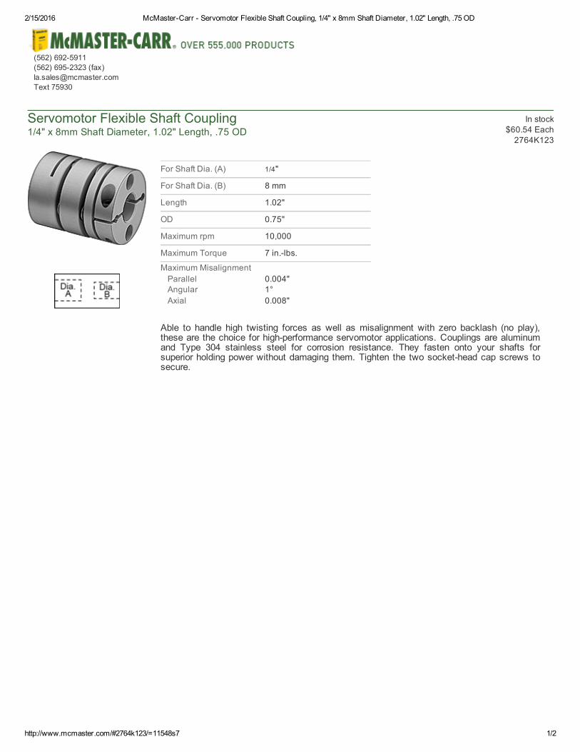
2/15/2016 McMasterCarr Servomotor Flexible Shaft Coupling, 1/4" x 8mm Shaft Diameter, 1.02" Length, .75 OD
http://www.mcmaster.com/#2764k123/=11548s7 1/2
Servomotor Flexible Shaft Coupling1/4" x 8mm Shaft Diameter, 1.02" Length, .75 OD
In stock$60.54 Each2764K123
For Shaft Dia. (A) 1/4"
For Shaft Dia. (B) 8 mm
Length 1.02"
OD 0.75"
Maximum rpm 10,000
Maximum Torque 7 in.lbs.
Maximum MisalignmentParallel 0.004"Angular 1°Axial 0.008"
Able to handle high twisting forces as well as misalignment with zero backlash (no play),these are the choice for highperformance servomotor applications. Couplings are aluminumand Type 304 stainless steel for corrosion resistance. They fasten onto your shafts forsuperior holding power without damaging them. Tighten the two sockethead cap screws tosecure.
(562) 6925911(562) 6952323 (fax)[email protected] 75930

2/15/2016 McMasterCarr Servomotor Flexible Shaft Coupling, 1/4" x 8mm Shaft Diameter, 1.02" Length, .75 OD
http://www.mcmaster.com/#2764k123/=11548s7 2/2
For Shaft Diameter (A): 1/4", For Shaft Diameter (B): 8 mm
The information in this 3D model is provided for reference only.

2/15/2016 McMasterCarr BallNose Spring Plunger with Stainless Steel Ball, Steel Body, 1/4"20 Thread, 412 lb. Nose Force
http://www.mcmaster.com/#3408a75/=1154jx4 1/1
BallNose Spring Plunger with Stainless Steel BallSteel Body, 1/4"20 Thread, 412 lb. Nose Force
$3.62 Each3408A75
Thread Size 1/4"20
Body Length (A) 0.531"
Nose Length (B) 0.035"
Nose Diameter (C) 0.125"
Nose Force, lbs.Extended 4Compressed 12
ThreadLocking Element With ThreadLocking Element, Without ThreadLockingElement
Additional Specifications Steel BodyStainless Steel BallInch
RoHS Compliant
The ball nose in these spring plungers rolls to minimize wear on the workpiece. They arecompact for highstrength. Install with a screwdriver or plunger wrench (sold separately).
Stainless steel balls are 440C, except Type 316 stainless steel plungers have Type 316stainless steel balls.
Maximum temperature is 250° F for steel and 188 stainless steel plungers withstainless steel ball and 170° F for all others.
To Order: Please specify with or without a threadlocking element. When threading intoaluminum and other soft materials, select a plunger without the threadlocking element.
(562) 6925911(562) 6952323 (fax)[email protected] 75930

2/15/2016 McMasterCarr ZincPlated Alloy Steel Socket Head Cap Screw, 1/4"20 Thread, 1/2" Length
http://www.mcmaster.com/#90128a242/=11547w6 1/2
ZincPlated Alloy Steel Socket Head Cap Screw1/4"20 Thread, 1/2" Length
In stock$9.09 per pack of 50
90128A242
Thread Size 1/4"20
Length 1/2"
Thread Length Full
Additional Specifications ZincPlated Alloy Steel
The standard among highstrength fasteners, these screws are stronger than Grade 8 steelscrews. They have a minimum tensile strength of 170,000 psi. and a minimum Rockwellhardness of C37. Length is measured from under the head.
Inch screws have a Class 3A thread fit. They meet ASTM A574.
Zinc Plated—Screws have a protective coating that adds corrosion resistance for outdoor use.
(562) 6925911(562) 6952323 (fax)[email protected] 75930

2/15/2016 McMasterCarr ZincPlated Alloy Steel Socket Head Cap Screw, 1/4"20 Thread, 1/2" Length
http://www.mcmaster.com/#90128a242/=11547w6 2/2
The information in this 3D model is provided for reference only.

2/15/2016 McMasterCarr Corrosion Resistant Dowel Pin, Type 316 Stainless Steel, 3/16" Diameter, 11/8" Length
http://www.mcmaster.com/#97395a474/=1154kdk 1/2
Corrosion Resistant Dowel PinType 316 Stainless Steel, 3/16" Diameter, 11/8" Length
In stock$11.25 per pack of 5
97395A474
Length 1 1/8"
Additional Specifications Type 316 Stainless Steel3/16" Dia.
RoHS Compliant
Pins are commonly used as pivots, hinges, shafts, jigs, and fixtures to locate orhold parts. They are precision ground (unless noted) for more accuratealignment, and slightly oversized for a tight fit. To aid insertion, ends arebeveled or rounded (unless noted). For a tight fit, your hole should be equal to orslightly smaller than the diameter shown. Breaking strength and Rockwellhardness are not rated (unless noted). Materials that have a breaking strengthare measured as double shear, which is the force required to break a pin intothree pieces.
Type 316 Stainless Steel—Our most corrosion resistant dowel pins. May bemagnetic. Diameter tolerance is +0.0002".
Not rated for breaking strength.
(562) 6925911(562) 6952323 (fax)[email protected] 75930

2/15/2016 McMasterCarr Corrosion Resistant Dowel Pin, Type 316 Stainless Steel, 3/16" Diameter, 11/8" Length
http://www.mcmaster.com/#97395a474/=1154kdk 2/2
The information in this 3D model is provided for reference only.

2/15/2016 McMasterCarr Magnetically Actuated Switch, Mini Cylindrical, SPDT, 150V DC
http://www.mcmaster.com/#65985k22/=11553wk 1/1
Magnetically Actuated SwitchMini Cylindrical, SPDT, 150V DC
In stock$46.11 Each65985K22
Amp Rating 0.8 amps @ 24V DC
Maximum Voltage 150 DC
Sensing Distance 0.2"
(A) 1.25"
(B) 0.31"
Housing Stainless Steel
Mounting Information 5/16"24 Threads
AdditionalSpecifications
Standard
DC Rated—Switch One Circuit from Off to On or On toOff (SPDT)
Mini Cylindrical
RoHS Compliant
Shipping Regulated by the U.S. Department of Transportation
With no moving parts to wear out, these switches provide longterm,troublefree service. When the magnet comes within the sensing distanceof the switch, the switch actuates. When the magnet moves away, theswitch resets. The switch is usually mounted in a stationary location suchas a door frame while the magnet is mounted on a movable object such asa door. Switches with mounting slots do not include hardware; switcheswith mounting threads include two hex nuts.
Standard switches are designed for proximitysensing applications such asdetecting when a door or window is open. Magnet included. They are not foruse on safetyguard doors found on machinery. DCrated switches havetwo wire leads except SPDT switches have three. UL and CULrecognized.
(562) 6925911(562) 6952323 (fax)[email protected] 75930

2/15/2016 McMasterCarr Metric HighPrecision Steel NeedleRoller Bearing, for 14 mm Shaft Diameter, 22 mm Outside Diameter
http://www.mcmaster.com/#2423k24/=1155dg0 1/2
Metric HighPrecision Steel NeedleRoller Bearingfor 14 mm Shaft Diameter, 22 mm Outside Diameter
In stock$19.11 Each
2423K24
Bearing Type Roller
Roller Type Needle
For Load Direction Radial
Shaft Mount Type Press Fit
Seal Type Open
For Shaft Diameter 14 mm
ID 14.000 mm
ID Tolerance 0.0160 to 0.0270 mm
OD 22 mm
OD Tolerance 0.0100 to 0.0000 mm
Width 16 mm
Width Tolerance 0.1200 to 0.0000 mm
Material Steel
Lubrication Required
Radial Load Capacity, lbs.Dynamic 2,270Static 2,600
Maximum Speed 24,000 rpm
Temperature Range 0° to 250° F
For Shaft Smoothness 4 microinches RA
Related Product Optional Shaft Liners
These precisionground bearings give you higher load capacity, speed, and accuracy than standardneedleroller bearings. They're for use on hardened and ground shafts. If your shaft is not hardenedand ground, use these bearings with liners (sold separately). Insert the liner into the bearing and pressfit onto a shaft. All bearings have a lubrication groove and hole, except for the bearings for 8 and 10mm shaft diameters.
Open dissipate heat more efficiently than doublesealed bearings.
(562) 6925911(562) 6952323 (fax)[email protected] 75930

2/15/2016 McMasterCarr Metric HighPrecision Steel NeedleRoller Bearing, for 14 mm Shaft Diameter, 22 mm Outside Diameter
http://www.mcmaster.com/#2423k24/=1155dg0 2/2
The information in this 3D model is provided for reference only.

Appendix E
Drive Shaft Analysis
Driven Shaft Analysis
Inertia Analysis
Worm Gear A Analysis
Worm Gear B Analysis
Bearing Analysis
Bolts Analysis

File:C:\Users\melab15\Desktop\Drive Shaft.EES 2/15/2016 9:21:34 AM Page 1EES Ver. 9.925: #0552: for use only by students and faculty, Mechanical Engineering, Dept. Cal Poly State University
Drive Shaft for 5th Axis RotaryThis code solves for the drive shaft deflection in the 4th and 5th rotary stages to prevent backlash while preventing failure. This
code also recommends a spring constant and calculates deflection from a given force. The shaft is 303 Stainless centerless ground
Geometric Parameters
DShaft = 0.25 [in] Shaft Diameter
L = 4 [in] Shaft Length
Material Properties
Sy = YieldStress StainlessAISI302 , T = 62.33 [F]
Sut = UltimateStress StainlessAISI302 , T = 62.33 [F]
E = YoungsModulus StainlessAISI302 , T = 62.33 [F]
a = 1.34 Ground Surface Finish (Table 6-2)
b = – 0.085 Ground Surface Finish (Table 6-2)
Spring Parameters
Shaft = 0.01 [in] Ideal Shaft Deflection
Spring = 0.15 [in] Ideal Spring Deflection
Force = 4 [lbf] Amount of Force to apply to the Shaft
Other
Ts = 150 [F] Case Temperature as calculated in Gear Wear
Solve for Spring Constant
I = ·
DShaft
2
4
4
[in4] Moment of Inertia for the Drive Shaft
k = Shaft · 3 · E · I
Spring · L 3 [lbf/in] Spring Constant for given deflections
Solve for Shaft Deflection Due to Assumed Force
ShaftDeflection = Force · L 3
3 · E · I[in] Resulting Shaft Deflection
Total Stress
Mz = Force · L [lbf*in] Moment in the z for the shaft
m = 32
· DShaft3
· Mz [psi] Maximum Bending Stress for a solid circular cross section (Equation 3-38)

File:C:\Users\melab15\Desktop\Drive Shaft.EES 2/15/2016 9:21:34 AM Page 2EES Ver. 9.925: #0552: for use only by students and faculty, Mechanical Engineering, Dept. Cal Poly State University
AShaft = · DShaft
2
2
[in2] Cross Sectional Area of the Shaft
= 4 · Force
3 · AShaft[psi] Transverse Shear Stress (Equation 3-31)
Total =
m
2 +
m
2
2
+ 2
1000 [psi/ksi]
[psi] Total Stress including bending and shear (Equation 3-14)
Se' = 0.5 · Sut [psi] Endurance Limit (Equation 6-8)
Ka = a · Sutb Surface Factor (Equation 6-19)
Kb = DShaft
0.3
– 0.107
Size Factor for diameters under 2in (Equation 6-20)
Kc = 1 Loading Factor for bending (Equation 6-26)
Kd = 0.975 + 0.000432 · Ts – 0.00000115 · Ts2 + 0 · Ts
3 – 5.95 x 10 –13 · Ts4
Temperature Factor at 150C
from heated oil (Equation 6-27)
Ke = 1 – 0.08 · 1.645 Reliability Factor of 95% (Equation 6-29)
Se = Ka · Kb · Kc · Kd · Ke · Se' [psi] Marin Equation for endurance limit (Equation 6-18)
nf = Se
TotalFactor of Safety
SOLUTION
Unit Settings: Eng F psia mass dega = 1.34 [-]AShaft = 0.04909 [in2]b = -0.085 [-]
Shaft = 0.01 [in]
Spring = 0.15 [in]DShaft = 0.25 [in]E = 2.799E+07 [psi]Force = 4 [lbf]I = 0.0001917 [in4]k = 16.77 [lbf/in]Ka = 0.9287 [-]Kb = 1.02 [-]Kc = 1 [-]Kd = 1.014 [-]Ke = 0.8684 [-]L = 4 [in]Mz = 16 [lbf*in]nf = 2.984 [-]nf = 2.984 [-]ShaftDeflection = 0.0159 [in]

File:C:\Users\melab15\Desktop\Drive Shaft.EES 2/15/2016 9:21:34 AM Page 3EES Ver. 9.925: #0552: for use only by students and faculty, Mechanical Engineering, Dept. Cal Poly State University
m = 10430 [psi]
Total = 10.43 [ksi]Se = 31.13 [ksi]Se' = 37.35 [ksi]Sut = 74.69 [ksi]Sy = 29.73 [ksi]
= 108.6 [psi]Ts = 150 [F]
3 potential unit problems were detected.


File:C:\Users\melab15\Downloads\Inertia.EES 2/13/2016 3:00:49 PM Page 1EES Ver. 9.925: #0552: for use only by students and faculty, Mechanical Engineering, Dept. Cal Poly State University
Moment of Inertia for 4th and 5th Axis Rotary Table
This code solves for load moment of inertia that the motors will
experience while driving the rotary. Each axis is input differently due
to different loads. Reflected moment of inertia is included with shaft and
coupling inertia to find the system inertia. Axis A inertia is calculated
using simplified geometry for rotary stage B.
Axis B Parameters
Hpart = 0.1 [m] Part Height
Dpart = 0.1 [m] Part Diameter
part = 900 [kg/m3] Part Density
Hplatter = 0.07 [m] Table Height
Dplatter = 0.1 [m] Platter Diameter
platter = 8000 [kg/m3] Table Density
Dshaft = 0.0047625 [m] Shaft Diameter (3/16in)
Lshaft = 0.1 [m] Shaft Length
shaft = 8000 [kg/m3] Shaft Density
Dcoupling = 0.015 [m] Coupling Diameter
Lcoupling = 0.0508 [m] Coupling Length
coupling = 2700 [kg/m3] Coupling Density
Dgear = 0.0254 [m] 30 Tooth Gear Diameter
Hgear = 0.00762 [m] Gear Width
gear = 8500 [kg/m3] Brass Gear Density
NB = 30 [-] Gear Teeth
Axis A Parameters
mB = 7 [kg] Axis B Mass
HB = 0.0762 [m] Axis B Height
LB = 0.1524 [m] Axis B Length
WB = 0.1524 [m] Axis B Width
OffsetB = 0.1 [m] Axis B offset to Axis A
MMotor,B = 0.5 [kg] Axis B Motor Mass

File:C:\Users\melab15\Downloads\Inertia.EES 2/13/2016 3:00:49 PM Page 2EES Ver. 9.925: #0552: for use only by students and faculty, Mechanical Engineering, Dept. Cal Poly State University
WMotor,B = 0.04 [m] Axis B Motor Width
NA = 30 Gear Teeth
BSolidWorks = 10 SolidWorks calculated inertia of axis B assembly
Solve for Axis B Inertia
Mpart = · Dpart
2
2
· Hpart · part [kg] Part Mass
Ipart = Mpart
8· Dpart
2[kg*m2] Part Inertia
Mplatter = · Dplatter
2
2
· Hplatter · platter [kg] Platter Mass
Iplatter = Mplatter
8· Dplatter
2[kg*m2 Platter Inertia
Mgear = · Dgear
2
2
· Hgear · gear [kg] Gear Mass
Igear = Mgear
8· Dgear
2[kg*m2] Gear Inertia
IReflected,B = Ipart + Iplatter + Igear
NB2 Find the Reflected Inertia
Mshaft = · Dshaft
2
2
· Lshaft · shaft [kg] Shaft Mass
Ishaft = Mshaft
8· Dshaft
2[kg*m2] Shaft Inertia
Mcoupling = · Dcoupling
2
2
· Lcoupling · coupling [kg] Coupling Mass
Icoupling = Mcoupling
8· Dcoupling
2[kg*m2] Coupling Inertia
InertiaTotal,B = IReflected,B + Ishaft + Icoupling Total Inertia Experienced by Motor at B-axis
Solve for Axis A Inertia
IB = mB
12 · LB
2 + HB2 + mB · OffsetB
2[kg*2] Inertia for Stage B Axis Through A Axis
IPart,A = Mpart
12 · 3 ·
Dpart
2
2
+ Hpart2 + Mpart · Hpart – OffsetB
2[kg*m2] Inertia for the Part

File:C:\Users\melab15\Downloads\Inertia.EES 2/13/2016 3:00:49 PM Page 3EES Ver. 9.925: #0552: for use only by students and faculty, Mechanical Engineering, Dept. Cal Poly State University
Imotor,B = MMotor,B
12 · 2 · WMotor,B
2 + MMotor,B · OffsetB2
[kg*m2] Inertia for Stage B Motor Through A Axis
IReflected,A = IB + IPart,A + Imotor,B + Igear
NA2 [kg*m2] Reflected Inertia Experienced by Motor A
Inertiatotal,A = IReflected,A + Ishaft + Icoupling [kg*m2]
SOLUTION
Unit Settings: SI C kPa kJ mass degBSolidWorks = 10 [kg*m2]Dcoupling = 0.015 [m]Dgear = 0.0254 [m]Dpart = 0.1 [m]Dplatter = 0.1 [m]Dshaft = 0.004763 [m]HB = 0.0762 [m]Hgear = 0.00762 [m]Hpart = 0.1 [m]Hplatter = 0.07 [m]Inertiatotal,A = 0.0001043 [kg*m2]Inertiatotal,A = 0.0001043 [kg*m2]InertiaTotal,B = 0.000007815 [kg*m2]InertiaTotal,B = 0.000007815 [kg*m2]IB = 0.08694 [kg*m2]Icoupling = 6.817E-07 [kg*m2]Igear = 0.000002647 [kg*m2]Imotor,B = 0.005267 [kg*m2]Ipart = 0.0008836 [kg*m2]IPart,A = 0.001031 [kg*m2]Iplatter = 0.005498 [kg*m2]IReflected,A = 0.0001036 [kg*m2]IReflected,B = 0.000007093 [kg*m2]Ishaft = 4.040E-08 [kg*m2]LB = 0.1524 [m]Lcoupling = 0.0508 [m]Lshaft = 0.1 [m]mB = 7 [kg]Mcoupling = 0.02424 [kg]Mgear = 0.03282 [kg]MMotor,B = 0.5 [kg]Mpart = 0.7069 [kg]Mplatter = 4.398 [kg]Mshaft = 0.01425 [kg]NA = 30 [-]NB = 30 [-]OffsetB = 0.1 [m]
coupling = 2700 [kg/m3]
gear = 8500 [kg/m3]
part = 900 [kg/m3]
platter = 8000 [kg/m3]
shaft = 8000 [kg/m3]WB = 0.1524 [m]WMotor,B = 0.04 [m]

File:C:\Users\melab15\Desktop\Worm Gear A.EES 2/15/2016 9:18:13 AM Page 1EES Ver. 9.925: #0552: for use only by students and faculty, Mechanical Engineering, Dept. Cal Poly State University
"Worm Gear Analysis"
"This code verifies the rated power for worm gears. From input parameters, this program predicts life time of a worm gear. Additionally, the gear case is analyzed for oil temperature. Values are found from eqautions in the Shigley engineering book"
"Conversions"Conv_hp = 746 [W/hp]
"Geometry Parameters"PitchDiameter_G = 1.875 [in] "Gear Pitch Diameter"PitchDiameter_W = 0.625 [in] "Worm Pitch Diameter"Speed = 100 [rev/min] "Speed of the Gear"N_G = 30 [-] "Number of gear teeth"N_W = 1 [-] "Number of worm teeth"P_in = 200[W] "Input Power"P_out = 90[W] "Required Output Power"dp = 16 [1/in] "Diametral Pitch of the gear"K_w = 100 [-] "Worm gear wear factor (Table 15-11)"t_Face = 0.312 [in] "Effective Face Width"PA = 14.5 [deg] "Normal Pressure Angle"K_a = 1.5 [-] "Application Factor (Table 15-2)"A_Case = 15 [in^2] "Gear Case Lateral Area"T_a = 70 [F] "Atmospheric Temperature"
C_s = 1000 [-] "Materials Factor for Chilled Cast Gears (Equation 15-34)"K_w_Buck = 60 [-] "Worm Gear Wear Factor From Buckingham (Table 15-11)"
"AGMA Method"p_x = pi/dp "[in] Axial Pitch"L = p_x*N_W "Lead of the worm"gamma = ARCTAN(L/(pi*PitchDiameter_W)) "[deg] Lead Angle of the worm"
p_n = pi/(dp/cos(gamma)) "[in] Normal Diametral Pitch"
V_s = pi*PitchDiameter_W*Speed*N_G "[in/min] Sliding Velocity"f = 0.103*exp(-0.110*(V_s^0.450))+0.012 "Friction Factor (Equation 15-62)"e = (cos(PA)-f*tan(gamma))/(cos(PA) + f/tan(gamma)) "Calculate the Efficiency (Equation 15-58)"
V_G = Speed*pi*PitchDiameter_G "[in/min] Gear Tangential Speed"
W_g_t = 33000*P_out*0.001341*K_a/(V_G*e) "[lbf] Tooth load (Equation 15-58)"
C_m = 0.0107*sqrt(-N_G^2+56*N_G+5145) "Ratio Correction Factor (Equation 15-37)"C_v = 62.52*V_s^(-0.774) "Velocity Correction Factor (Equation 15-38)"
W_t_all = C_s*(N_G/dp)^0.8*t_Face*C_m*C_v "[lbf] Allowable Tangential Force on Worm (Equation 15-28)"
W_f = f*W_g_t/(f*sin(gamma)-cos(14.5[deg])*cos(gamma)) "[lbf] Friction Force (Equation 15-61)"H_f = abs(W_f)*v_s*0.001341/33000 "[W] Power Dissapated in Frictional Work (Equation 15-63)"
Sigma_G = W_g_t/(p_n*t_Face*0.1) "[psi] Bending Stress in a Gear Tooth from Buckingham adapted Lewis Equation and form Facor Equation 15-53)"
n_f = W_t_all/W_g_t "Factor of Safety for 25000 hours"
"Buckingham Wear Load"W_Buck = K_w_Buck*PitchDiameter_G*t_Face "[lbf] Allowable gear loading for wear (Equation 15-64)"
"Gear Case Temperature"H_loss = 33000*(1-e)*P_in*0.001341 "[ft*lbf/min] Heat Loss Rate from the Worm Gear Case (Equation 15-49)"h_CR = Speed*N_G/6494+0.13 " [ft*lbf/(min*in^2*F)] Heat Transfer Coefficient for Convection and Radiation (Equation 15-50)"

File:C:\Users\melab15\Desktop\Worm Gear A.EES 2/15/2016 9:18:13 AM Page 2EES Ver. 9.925: #0552: for use only by students and faculty, Mechanical Engineering, Dept. Cal Poly State University
t_s = T_a + H_loss/(h_CR*A_Case) "[F] Oil Sump Temperature (Equation 15-51)"
A_min = 43.2*((PitchDiameter_W+PitchDiameter_G)/2)^1.7 "[in^2] AGMA Recommended Minimum Lateral Area (Equation 15-52)"
SOLUTION
Unit Settings: Eng F psia mass degACase = 15 [in2]Amin = 63.13 [in2]Convhp = 746 [W/hp]Cm = 0.8236 [-]Cs = 1000 [-]Cv = 0.0755 [-]dp = 16 [1/in]e = 0.885 [-]f = 0.01243 [-]
= 5.711 [deg]hCR = 0.592 [ft*lbf/(min*in2*F)]Hf = 0.00003545 Hloss = 1017 [ft*lbf/min]Ka = 1.5 [-]Kw = 100 [-]Kw,Buck = 60 [-]L = 0.1963 [in]nf = 2.799 [-]nf = 2.799 [-]NG = 30 [-]NW = 1 [-]PA = 14.5 [deg]PitchDiameterG = 1.875 [in]PitchDiameterW = 0.625 [in]Pin = 200 [W]pn = 0.1954 [in]Pout = 90 [W]px = 0.1963 [in]
G = 1880 [psi]Speed = 100 [rev/min]Ta = 70 [F]tFace = 0.312 [in]ts = 184.6 [F]VG = 589 [in/min]Vs = 5890 [in/min]WBuck = 35.1 [lbf]Wf = -0.1481 [lbf]Wg,t = 11.46 [lbf]Wt,all = 32.08 [lbf]
11 potential unit problems were detected.
KEY VARIABLESnf = 2.799 [-]nf = 2.799 [-] Factor of Safety for 25000 hours
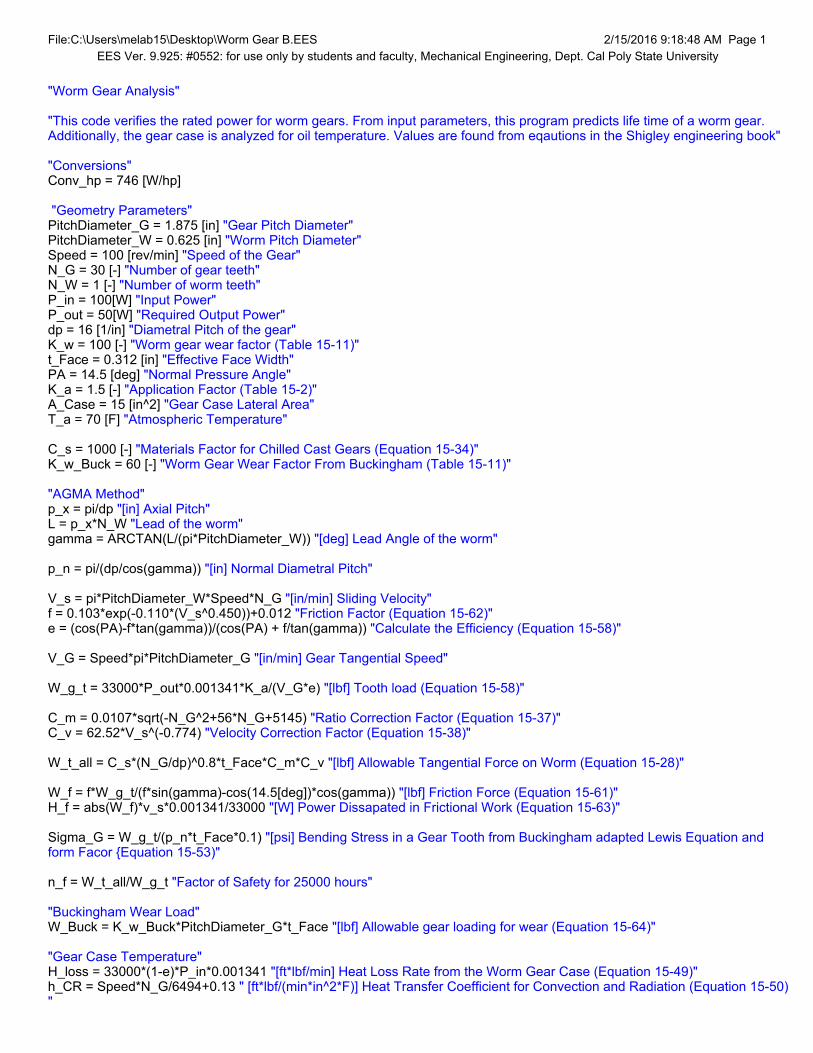
File:C:\Users\melab15\Desktop\Worm Gear B.EES 2/15/2016 9:18:48 AM Page 1EES Ver. 9.925: #0552: for use only by students and faculty, Mechanical Engineering, Dept. Cal Poly State University
"Worm Gear Analysis"
"This code verifies the rated power for worm gears. From input parameters, this program predicts life time of a worm gear. Additionally, the gear case is analyzed for oil temperature. Values are found from eqautions in the Shigley engineering book"
"Conversions"Conv_hp = 746 [W/hp]
"Geometry Parameters"PitchDiameter_G = 1.875 [in] "Gear Pitch Diameter"PitchDiameter_W = 0.625 [in] "Worm Pitch Diameter"Speed = 100 [rev/min] "Speed of the Gear"N_G = 30 [-] "Number of gear teeth"N_W = 1 [-] "Number of worm teeth"P_in = 100[W] "Input Power"P_out = 50[W] "Required Output Power"dp = 16 [1/in] "Diametral Pitch of the gear"K_w = 100 [-] "Worm gear wear factor (Table 15-11)"t_Face = 0.312 [in] "Effective Face Width"PA = 14.5 [deg] "Normal Pressure Angle"K_a = 1.5 [-] "Application Factor (Table 15-2)"A_Case = 15 [in^2] "Gear Case Lateral Area"T_a = 70 [F] "Atmospheric Temperature"
C_s = 1000 [-] "Materials Factor for Chilled Cast Gears (Equation 15-34)"K_w_Buck = 60 [-] "Worm Gear Wear Factor From Buckingham (Table 15-11)"
"AGMA Method"p_x = pi/dp "[in] Axial Pitch"L = p_x*N_W "Lead of the worm"gamma = ARCTAN(L/(pi*PitchDiameter_W)) "[deg] Lead Angle of the worm"
p_n = pi/(dp/cos(gamma)) "[in] Normal Diametral Pitch"
V_s = pi*PitchDiameter_W*Speed*N_G "[in/min] Sliding Velocity"f = 0.103*exp(-0.110*(V_s^0.450))+0.012 "Friction Factor (Equation 15-62)"e = (cos(PA)-f*tan(gamma))/(cos(PA) + f/tan(gamma)) "Calculate the Efficiency (Equation 15-58)"
V_G = Speed*pi*PitchDiameter_G "[in/min] Gear Tangential Speed"
W_g_t = 33000*P_out*0.001341*K_a/(V_G*e) "[lbf] Tooth load (Equation 15-58)"
C_m = 0.0107*sqrt(-N_G^2+56*N_G+5145) "Ratio Correction Factor (Equation 15-37)"C_v = 62.52*V_s^(-0.774) "Velocity Correction Factor (Equation 15-38)"
W_t_all = C_s*(N_G/dp)^0.8*t_Face*C_m*C_v "[lbf] Allowable Tangential Force on Worm (Equation 15-28)"
W_f = f*W_g_t/(f*sin(gamma)-cos(14.5[deg])*cos(gamma)) "[lbf] Friction Force (Equation 15-61)"H_f = abs(W_f)*v_s*0.001341/33000 "[W] Power Dissapated in Frictional Work (Equation 15-63)"
Sigma_G = W_g_t/(p_n*t_Face*0.1) "[psi] Bending Stress in a Gear Tooth from Buckingham adapted Lewis Equation and form Facor Equation 15-53)"
n_f = W_t_all/W_g_t "Factor of Safety for 25000 hours"
"Buckingham Wear Load"W_Buck = K_w_Buck*PitchDiameter_G*t_Face "[lbf] Allowable gear loading for wear (Equation 15-64)"
"Gear Case Temperature"H_loss = 33000*(1-e)*P_in*0.001341 "[ft*lbf/min] Heat Loss Rate from the Worm Gear Case (Equation 15-49)"h_CR = Speed*N_G/6494+0.13 " [ft*lbf/(min*in^2*F)] Heat Transfer Coefficient for Convection and Radiation (Equation 15-50)"

File:C:\Users\melab15\Desktop\Worm Gear B.EES 2/15/2016 9:18:48 AM Page 2EES Ver. 9.925: #0552: for use only by students and faculty, Mechanical Engineering, Dept. Cal Poly State University
t_s = T_a + H_loss/(h_CR*A_Case) "[F] Oil Sump Temperature (Equation 15-51)"
A_min = 43.2*((PitchDiameter_W+PitchDiameter_G)/2)^1.7 "[in^2] AGMA Recommended Minimum Lateral Area (Equation 15-52)"
SOLUTION
Unit Settings: Eng F psia mass degACase = 15 [in2]Amin = 63.13 [in2]Convhp = 746 [W/hp]Cm = 0.8236 [-]Cs = 1000 [-]Cv = 0.0755 [-]dp = 16 [1/in]e = 0.885 [-]f = 0.01243 [-]
= 5.711 [deg]hCR = 0.592 [ft*lbf/(min*in2*F)]Hf = 0.00001969 Hloss = 508.7 [ft*lbf/min]Ka = 1.5 [-]Kw = 100 [-]Kw,Buck = 60 [-]L = 0.1963 [in]nf = 5.039 [-]nf = 5.039 [-]NG = 30 [-]NW = 1 [-]PA = 14.5 [deg]PitchDiameterG = 1.875 [in]PitchDiameterW = 0.625 [in]Pin = 100 [W]pn = 0.1954 [in]Pout = 50 [W]px = 0.1963 [in]
G = 1044 [psi]Speed = 100 [rev/min]Ta = 70 [F]tFace = 0.312 [in]ts = 127.3 [F]VG = 589 [in/min]Vs = 5890 [in/min]WBuck = 35.1 [lbf]Wf = -0.08228 [lbf]Wg,t = 6.366 [lbf]Wt,all = 32.08 [lbf]
11 potential unit problems were detected.
KEY VARIABLESnf = 5.039 [-]nf = 5.039 [-] Factor of Safety for 25000 hours

File:C:\Users\melab15\Desktop\Bearings.EES 2/15/2016 11:29:19 AM Page 1EES Ver. 9.925: #0552: for use only by students and faculty, Mechanical Engineering, Dept. Cal Poly State University
"Bearings""This code solves for bearing performance."
"NSK 7006CTYNDBL P4 ABEC-7""Basic Load Ratings"C_r = 3400 [lbf] "Basic Dynamic Load Rating"C_or = 2310 [lbf] "Basic Static Load Rating"C_axial = 1540 [lbf] "Permissible Axial Load"
"Geometrical Parameters"a = 0.48 [in] "Effective Load Center"
"Design Parameters"h_part = 4 [in] "Part Height"F_design = 18 [lbf] "80 N Cutting Force"m_B = 20 [lbf] "Weight of axis" L_B = 6 [in] "Length of B Axis"N_design = 100 [rev/min] "Platter Rotational Speed"
"Limiting Speeds"N|grease_max = 27100 [rev/min] "Maximum rated speed for greased bearings"N|oil_max = 41200 [rev/min] "Maximum rated speed for oiled bearings"
"Rated Load"M_rated = a * C_or "[lbf-in] Rated Moment"
"Design Load"M|B_design = h_part * F_design "[lbf-in] Axis B Design Moment"M|A_design = F_design * L_B + m_B * L_B/2 "[lbf-in] Axis A Design Moment"
"Factors of Safety"eta|B_M = M_rated/M|B_design "Axis B Factor of Safety for Bending Moment"eta|B_A = C_axial/F_design "Axis B Factor of Safety for Axial Loading"
eta|A_M = M_rated/M|A_design "Axis A Factor of Safety for Bending Moment"eta|A_A = C_axial / (m_B + F_design) "Axis A Factor of Safety for Axial Loading"
eta_N = N|grease_max/N_design "Factor of Safety for Speed Rating"
SOLUTION
Unit Settings: Eng F psia mass dega = 0.48 [in]Caxial = 1540 [lbf]Cor = 2310 [lbf]Cr = 3400 [lbf]
N = 271 [-]
AA = 40.53 [-]
AM = 6.6 [-]AM = 6.6 [-]
BA = 85.56 [-]
BM = 15.4 [-]
Fdesign = 18 [lbf]hpart = 4 [in]LB = 6 [in]mB = 20 [lbf]Mrated = 1109 [lbf*in]M
Adesign = 168 [lbf*in]
MBdesign = 72 [lbf*in]
Ndesign = 100 [rev/min]

File:C:\Users\melab15\Desktop\Bearings.EES 2/15/2016 11:29:19 AM Page 2EES Ver. 9.925: #0552: for use only by students and faculty, Mechanical Engineering, Dept. Cal Poly State University
Ngreasemax = 27100 [rev/min]
Noilmax = 41200 [rev/min]
No unit problems were detected.

File:C:\Users\melab15\Downloads\Bolts Analysis.EES 2/15/2016 10:48:28 AM Page 1EES Ver. 9.925: #0552: for use only by students and faculty, Mechanical Engineering, Dept. Cal Poly State University
Using 1/4-20 bolts, Grade 1
F = 45 [lbf] weight+cutting force
M = 45 · 3 [in-lbf] Moment
t = 0.5 [in] fixture plate thickness
d = 0.25 [in] bolt nominal diameter
Area = · d 2
4bolt area
n = 4 number of bolts
Sy,mem = 40000 [psi] 6061 Al - Yield Strength
Sut,mem = 45000 [psi] 6061 Al - Yield Strength
Sy = 36000 [psi] Grade 1 Steel - Yield Strength (Table 8-9)
Sp = 33000 [psi] Grade 1 Steel - Proof Strength (Table 8-9)
Sut = 60000 [psi] Grade 1 Steel - Ultimate Tensile Strength (Table 8-9)
Fixture plate attaching to Axis B
Bending Stress
bend = M · c
I
I = 1
12· b · h 3
Moment of Inertia
b = 6 [in] Base of Housing
h = 3 [in] Height of Housing
c = 1.5 [in] distance from neutral axis
a = 1 [in] distance from edge
B,bend = Sy
bendBending Stress Safety Factor for B
Bearing stress
b = F
t · d
B,bearing = Sy
bBearing Stress Safety Factor for B
Shear stress

File:C:\Users\melab15\Downloads\Bolts Analysis.EES 2/15/2016 10:48:29 AM Page 2EES Ver. 9.925: #0552: for use only by students and faculty, Mechanical Engineering, Dept. Cal Poly State University
= F
4 · · d 2
4
B,shear = 0.577 · Sy
Shear Stress Safety Factor for B
Edge shearing of member
edge = F
4 · a · t
B,edge = 0.577 · Sy,mem
edgeEdge shearing of member Safety Factor for B
Bolt pattern attaching fixture plate to Axis A
r = 3 [in] radii of bolt pattern
F1 = F
nprimary shear load
F2 = M · r
4 · r 2 secondary shear load
= 30 [deg] 90 to 180 deg. first bolt
FA,x = F2 · sin x component of bolt
FA,y = F1 + F2 · cos y component of bolt
FA = FA,x2 + FA,y
2 Total force on bolt
= 60 [deg] 180 deg to 270 deg
FC,x = F2 · sin x component of bolt
FC,y = F2 · cos – F1 y component of bolt
FC = FC,x2 + FC,y
2 Total force on bolt
largest stress at 0 deg
FB = F1 + F2 The largest stress is seen when rotated 90 deg with bolt at 0 deg
shear stress
A = FB
Area
A,shear = 0.577 · Sy
A

File:C:\Users\melab15\Downloads\Bolts Analysis.EES 2/15/2016 10:48:29 AM Page 3EES Ver. 9.925: #0552: for use only by students and faculty, Mechanical Engineering, Dept. Cal Poly State University
Bearing stress
A,b = – FB
Area
A,b = Sy
A,bBearing Stress Safety Factor for A
Critical bending stress
Ib = I + 3 · Iholes + r 2 · 0.25 [in] · 0.25 [in] Total moment of inertia, Area is bolt diam*thickness
I = 0.5 · 4 3
12· 1 [in4] Cross section inertia of fixture plate
Iholes = 0.5 · 0.25 3
12· 1 [in4] Inertia of holes
A,bend = M · 2 [in]
Ib
A,bend = Sy
A,bendCritical Bending Stress Safety Factor for A
At = 0.031 Tensile stress area
As = 0.25 · Es Shear area of screw
An = 0.25 · Kn Shear area of hole
Kn = 0.1876 [psi] Internal minor diameter of hole
nt = 20 Number of threads
Es = 0.2164 Min pitch diameter of external threads
Le = 2 · At
Kn · · 0.5 + 0.577 · n · Es – KnLength of engagement
J = As · Sut
An · Sut,memFor screwing steel into aluminum
Lef = Le · J New length of engagement
SOLUTION
Unit Settings: Eng F psia mass dega = 1 [in] = 30 [deg]Area = 0.04909 [in2] An = 0.0469 [psi]As = 0.0541 [psi] At = 0.031 [psi]b = 6 [in] = 60 [deg]c = 1.5 [in]

File:C:\Users\melab15\Downloads\Bolts Analysis.EES 2/15/2016 10:48:29 AM Page 4EES Ver. 9.925: #0552: for use only by students and faculty, Mechanical Engineering, Dept. Cal Poly State University
A,b = -78.54 A,bend = 580.8
A,shear = 45.32 A,shear = 45.32 B,bearing = 100
B,bend = 2400 B,edge = 1026
B,shear = 90.63 B,shear = 90.63 Es = 0.2164 [in]F = 45 [lbf] F1 = 11.25 [lbf]F2 = 11.25 [lbf] FA = 21.73 [lbf]FA,x = 5.625 [lbf] FA,y = 20.99 [lbf]FB = 22.5 [lbf] FC = 11.25 [lbf]FC,x = 9.743 [lbf] FC,y = -5.625 [lbf]h = 3 [in] I = 13.5 [in4]Ib = 4.356 [in4] I = 2.667 [in4]Iholes = 0.000651 [in4] J = 1.538 [-]Kn = 0.1876 [psi] Le = 0.1857 [in]Lef = 0.2856 [in]Lef = 0.2856 [in] M = 135 [lbf*in]n = 4 nt = 20 r = 3 [in] A,b = -458.4 [psi]
A,bend = 61.98 [psi] b = 360 [psi]
bend = 15 [psi] Sp = 33000 [psi]Sut = 60000 [psi] Sut,mem = 45000 [psi]Sy = 36000 [psi] Sy,mem = 40000 [psi]t = 0.5 [in] = 229.2 [psi]
A = 458.4 [psi] edge = 22.5 [psi]
2 potential unit problems were detected.

Appendix F
DVP&R
FMEA

Report Date: 1/27/2016 Sponsor: IME Dept (Jose Macedo / Martin Koch) Component/Assembly Rotary Table REPORTING ENGINEER:
Quantity Type Start date Finish date Test Result Quantity Pass Quantity Fail1 Specification 3.5 Vibrations Test Natural frequency > 2500 Hz Ricky DV 1 B 2/8/2016 2/18/2016 Fail 0 1 Frequency ~400Hz, conclusive2 Specification 12.2 Gear Wear Test life cycle > 2400 Hrs Dakota DV 1 B - - - - - Incomplete
3Specification 2.4 Backlash Test Gears must perfectly mesh Irene CV 1 A 5/12/2016 5/15/2016 Pass 1 0 Manually adjust spring plunger to mesh
4 Specification 2.3 Accuracy Test (Axis B) Dakota DV 1 B - - - - - Incomplete5 Specification 2.3 Accuracy Test (Axis A) Irene DV 1 B - - - - - Incomplete6 Oil Temperature Test Temperature of oil < Nicole PV 1 C - - - - - Incomplete7 Oil Leakage Test No leaks Irene CV 1 A - - - - - Incomplete8 Motor Torque Curves Curves match given Nicole PV 1 C Motors changed, could not test9 Power Requirement Works with Haas Machine Ricky PV 1 C Incomplete
10Specification 9.1 Tolerances / Runnout Tolerance < 0.01 in Ricky DV 1 B 3/5/2016 3/7/2016 Pass 1 0 Dimensions checked with Optical
Comparator, deviations of 0.00211 Specification 2.1 Speed Test (Axis B) Speed > 30 rpm Nicole DV 1 B 4/31/2016 5/1/2016 Pass 1 012 Specification 2.2 Speed Test (Axis A) Speed > 30 rpm Nicole DV 1 B 4/31/2016 5/1/2016 Pass 1 0
Test Responsibility
Test StageSAMPLES TIMING TEST RESULTS
NOTES
ME428/ME481 DVP&R Format
TEST PLAN TEST REPORTItemNo
Specification or Clause Reference Test Description Acceptance Criteria
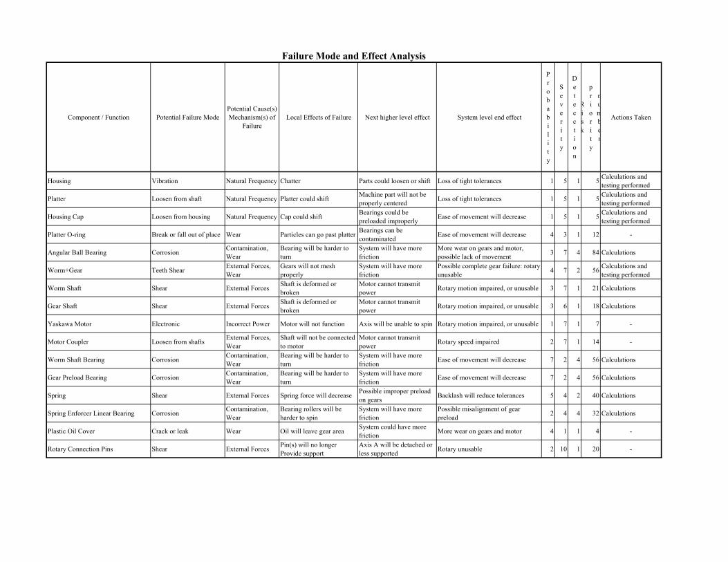
Component / Function Potential Failure ModePotential Cause(s) Mechanism(s) of
FailureLocal Effects of Failure Next higher level effect System level end effect
Probability
Severity
Detecction
Risk
priority
number
Actions Taken
Housing Vibration Natural Frequency Chatter Parts could loosen or shift Loss of tight tolerances 1 5 1 5 Calculations and testing performed
Platter Loosen from shaft Natural Frequency Platter could shift Machine part will not be properly centered Loss of tight tolerances 1 5 1 5 Calculations and
testing performed
Housing Cap Loosen from housing Natural Frequency Cap could shift Bearings could be preloaded improperly Ease of movement will decrease 1 5 1 5 Calculations and
testing performed
Platter O-ring Break or fall out of place Wear Particles can go past platter Bearings can be contaminated Ease of movement will decrease 4 3 1 12 -
Angular Ball Bearing Corrosion Contamination, Wear
Bearing will be harder to turn
System will have more friction
More wear on gears and motor, possible lack of movement 3 7 4 84 Calculations
Worm+Gear Teeth Shear External Forces, Wear
Gears will not mesh properly
System will have more friction
Possible complete gear failure: rotary unusable 4 7 2 56 Calculations and
testing performed
Worm Shaft Shear External Forces Shaft is deformed or broken
Motor cannot transmit power Rotary motion impaired, or unusable 3 7 1 21 Calculations
Gear Shaft Shear External Forces Shaft is deformed or broken
Motor cannot transmit power Rotary motion impaired, or unusable 3 6 1 18 Calculations
Yaskawa Motor Electronic Incorrect Power Motor will not function Axis will be unable to spin Rotary motion impaired, or unusable 1 7 1 7 -
Motor Coupler Loosen from shafts External Forces, Wear
Shaft will not be connected to motor
Motor cannot transmit power Rotary speed impaired 2 7 1 14 -
Worm Shaft Bearing Corrosion Contamination, Wear
Bearing will be harder to turn
System will have more friction Ease of movement will decrease 7 2 4 56 Calculations
Gear Preload Bearing Corrosion Contamination, Wear
Bearing will be harder to turn
System will have more friction Ease of movement will decrease 7 2 4 56 Calculations
Spring Shear External Forces Spring force will decrease Possible improper preload on gears Backlash will reduce tolerances 5 4 2 40 Calculations
Spring Enforcer Linear Bearing Corrosion Contamination, Wear
Bearing rollers will be harder to spin
System will have more friction
Possible misalignment of gear preload 2 4 4 32 Calculations
Plastic Oil Cover Crack or leak Wear Oil will leave gear area System could have more friction More wear on gears and motor 4 1 1 4 -
Rotary Connection Pins Shear External Forces Pin(s) will no longer Provide support
Axis A will be detached or less supported Rotary unusable 2 10 1 20 -
Failure Mode and Effect Analysis

Appendix G
Gantt Chart

ID Task Mode
Task Name Duration Start Finish
1
2 Brainstorming 39 days Mon 9/21/15 Thu 11/12/153 Specifications 14 days Thu 10/15/15 Tue 11/3/154 Project Proposal 21 days Fri 10/9/15 Fri 11/6/155 Concept Generation 31 days Tue 10/20/15 Tue 12/1/156 Analysis+Prototyping 40 days Mon 11/2/15 Fri 12/25/157 PDR 2 days Thu 11/12/15 Fri 11/13/158 Prototype 1 25 days Fri 1/1/16 Thu 2/4/169 Finish CAD 7 days Mon 1/4/16 Tue 1/12/1610 CAM/Machine Part 14 days Mon 1/11/16 Thu 1/28/1611 Assembly 5 days Sat 1/30/16 Thu 2/4/1612 CDR Prep 7 days Wed 1/27/16 Thu 2/4/1613 CDR 10 days Thu 2/4/16 Wed 2/17/1614 Testing 23 days Mon 2/1/16 Tue 3/1/1615 Vibrations Test 12 days Mon 2/15/16 Mon 2/29/1616 4th Axis 41 days Tue 3/1/16 Sun 4/24/1617 Parts Ordering 9 days Tue 3/1/16 Thu 3/10/1618 CAM 2 6 days Tue 3/1/16 Mon 3/7/1619 Manufacturing 21 days Tue 3/1/16 Mon 3/28/1620 Shaft 2 days Fri 3/4/16 Sat 3/5/1621 Platter 3 days Mon 3/7/16 Wed 3/9/1622 Preload 4 days Wed 3/9/16 Sat 3/12/1623 Housing 6 days Mon 3/14/16 Sun 3/20/16
BrainstormingSpecifications
Project ProposalConce
PDR
T M S S F T W T M S S F T W T/13 9/27 10/11 10/25 11/8 11/22 12/6
Task
Split
Milestone
Summary
Project Summary
Inactive Task
Inactive Milestone
Inactive Summary
Manual Task
Duration-only
Manual Summary Rollup
Manual Summary
Start-only
Finish-only
External Tasks
External Milestone
Deadline
Progress
Manual Progress
Slippage
Page 1
Project: Project1Date: Thu 6/2/16

ID Task Mode
Task Name Duration Start Finish
24 Cap 5 days Sun 3/20/16 Thu 3/24/1625 Assembly 2 26 days Fri 3/18/16 Fri 4/22/1626 Testing 2 22 days Mon 4/4/16 Sat 4/30/1627 Vibrations Test 5 days Tue 4/5/16 Mon 4/11/1628 Motor & Accuracy Test 6 days Mon 4/25/16 Sat 4/30/1629 Does it work??? 6 days Mon 4/25/16 Sat 4/30/1630 Software Integration 32 days Mon 3/14/16 Mon 4/25/1631 5th Axis 20 days Sun 4/24/16 Wed 5/18/1632 CAD 3 3 days Sun 4/24/16 Tue 4/26/1633 CAM 3 5 days Tue 4/26/16 Sat 4/30/1634 Parts Ordering 2 days Mon 4/25/16 Tue 4/26/1635 Manufacturing 3 16 days Mon 4/25/16 Fri 5/13/1636 Shaft 2 days Mon 5/2/16 Tue 5/3/1637 Adapter Plates 8 days Wed 5/4/16 Fri 5/13/1638 Preload 2 days Sun 5/8/16 Mon 5/9/1639 Cap 6 days Mon 5/2/16 Sat 5/7/1640 Housing 16 days Mon 4/25/16 Fri 5/13/1641 Assembly 3 4 days Sat 5/14/16 Wed 5/18/1642 Testing 3 6 days Thu 5/19/16 Thu 5/26/1643 Motor & Accuracy Test 4 days Thu 5/19/16 Tue 5/24/1644 Does it work??? 6 days Thu 5/19/16 Thu 5/26/1645 Hardware/Software 9 days Mon 5/16/16 Thu 5/26/1646 Poster 5 days Mon 5/23/16 Fri 5/27/16
T M S S F T W T M S S F T W T/13 9/27 10/11 10/25 11/8 11/22 12/6
Task
Split
Milestone
Summary
Project Summary
Inactive Task
Inactive Milestone
Inactive Summary
Manual Task
Duration-only
Manual Summary Rollup
Manual Summary
Start-only
Finish-only
External Tasks
External Milestone
Deadline
Progress
Manual Progress
Slippage
Page 2
Project: Project1Date: Thu 6/2/16
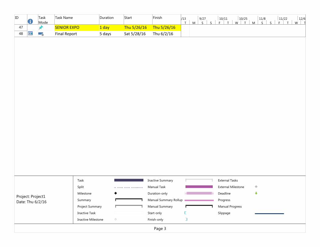
ID Task Mode
Task Name Duration Start Finish
47 SENIOR EXPO 1 day Thu 5/26/16 Thu 5/26/1648 Final Report 5 days Sat 5/28/16 Thu 6/2/16
T M S S F T W T M S S F T W T/13 9/27 10/11 10/25 11/8 11/22 12/6
Task
Split
Milestone
Summary
Project Summary
Inactive Task
Inactive Milestone
Inactive Summary
Manual Task
Duration-only
Manual Summary Rollup
Manual Summary
Start-only
Finish-only
External Tasks
External Milestone
Deadline
Progress
Manual Progress
Slippage
Page 3
Project: Project1Date: Thu 6/2/16

oncept GenerationAnalysis+Prototyping
Prototype 1Finish CAD
CAM/Machine PartAssembly
CDR PrepCDR
TestingVibrations Test
4th AxisParts Ordering
CAM 2Manufacturing
ShaftShaftPlatter
PreloadHousing
T M S S F T W T M S S F T W T M S S F T W T M S S F T W T M S S F T2/6 12/20 1/3 1/17 1/31 2/14 2/28 3/13 3/27 4/10 4/24 5/8 5/22 6/5 6/19
Task
Split
Milestone
Summary
Project Summary
Inactive Task
Inactive Milestone
Inactive Summary
Manual Task
Duration-only
Manual Summary Rollup
Manual Summary
Start-only
Finish-only
External Tasks
External Milestone
Deadline
Progress
Manual Progress
Slippage
Page 4
Project: Project1Date: Thu 6/2/16

CapAssembly 2
Testing 2Vibrations Test
Motor & Accuracy TestDoes it work???
Software Integration5th Axis
CAD 3CAM 3
Parts OrderingManufacturing 3
ShaftShaftAdapter Plates
PreloadCap
HousingAssembly 3
Testing 3Motor & Accuracy Test
Does it work???Hardware/SoftwarePoster
T M S S F T W T M S S F T W T M S S F T W T M S S F T W T M S S F T2/6 12/20 1/3 1/17 1/31 2/14 2/28 3/13 3/27 4/10 4/24 5/8 5/22 6/5 6/19
Task
Split
Milestone
Summary
Project Summary
Inactive Task
Inactive Milestone
Inactive Summary
Manual Task
Duration-only
Manual Summary Rollup
Manual Summary
Start-only
Finish-only
External Tasks
External Milestone
Deadline
Progress
Manual Progress
Slippage
Page 5
Project: Project1Date: Thu 6/2/16

SENIOR EXPOFinal Report
T M S S F T W T M S S F T W T M S S F T W T M S S F T W T M S S F T2/6 12/20 1/3 1/17 1/31 2/14 2/28 3/13 3/27 4/10 4/24 5/8 5/22 6/5 6/19
Task
Split
Milestone
Summary
Project Summary
Inactive Task
Inactive Milestone
Inactive Summary
Manual Task
Duration-only
Manual Summary Rollup
Manual Summary
Start-only
Finish-only
External Tasks
External Milestone
Deadline
Progress
Manual Progress
Slippage
Page 6
Project: Project1Date: Thu 6/2/16

Appendix H Operator’s Manual

Operator’s Manual
To Install the Rotary Table
1. Supporting the B‐axis with one hand and holding the A‐axis with the other, lift the rotary table onto the mill table. NOTE: Be careful when placing the rotary on the mill table to avoid pinching.
2. Use a 1‐2‐3 Block to support the bottom of the B‐axis and to prevent the rotary from tipping. 3. Align the rotary table with the T‐slots on the mill table. 4. Using toe clamps secure the rotary table to the mill table.
Connecting the Rotary Table to the Controller
1. Select two connectors with the same color 2. Push in the connectors being sure to align the keyway, and twist on the cover.
Connecting the Controller to the Machine
1. Connect power cord of controller to a 120V outlet. 2. Turn on the controller to ensure that the fan works. 3. Plug in the serial cable into the serial port on the CNC machine.