Embed Size (px)
Citation preview
1
4th IAA Planetary Defense Conference – PDC 2015 April 2015, Frascati, Roma, Italy
IAA-PDC-15-03-07
Effective Planetary Defense using Directed Energy DE-STARLITE
Philip Lubin1, Travis Brashears1, Gary Hughes2, Qicheng Zhang1, Janelle Griswald1, Kelly Kosmo1
1Physics Department, UC Santa Barbara, Santa Barbara, CA 93106 2Statistics Department, California Polytechnic State Univ., San Luis Obispo, CA 93407
Abstract— We show that Directed Energy (DE) systems offer the potential for true planetary defense from small to km class threats. Directed energy has evolved dramatically recently and is on an extremely rapid ascent technologically. It is now feasible to consider DE systems for threats from asteroids and comets. DE-STAR (Directed Energy System for Targeting of Asteroids and exploRation) is a phased-array laser directed energy system intended for illumination, deflection and compositional analysis of asteroids [1]. It can be configured either as a stand-on or a distant stand-off system. A system of appropriate size would be capable of projecting a laser spot onto the surface of a distant asteroid with sufficient flux to heat a spot on the surface to approximately 3,000 K, adequate to vaporize solid rock. Mass ejection due to vaporization creates considerable reactionary thrust to divert the asteroid from its orbit. DE-STARLITE is a smaller stand-on system that utilizes the same technology as the larger standoff system, but with a much smaller laser for a dedicated mission to a specific asteroid. DE-STARLITE offers a very power and mass efficient approach to planetary defense. As an example, a DE-STARLITE system that fits within the mass and size constraints of the Asteroid Redirect Mission (ARM) system in a small portion of the SLS block 1 launch capability is capable of deflecting an Apophis class (325 m diameter) asteroid with sufficient warning. A DE-STARLITE using the full SLS block 1 launch mass can deflect any known threat. We propose a logical approach to planetary defense is to pre-deploy DE-STARLITE systems in LEO or GEO rather that start a build when a threat arises. In the times when the system is not being used for planetary defense it can be used for many other tasks including orbital debris removal. Pre-deployment allows for rapid repose to threats and is a far superior approach to waiting for a threat before a mission start. We compare DE-STARLITE to other deflections possibilities including impactor and ion beam deflection missions with the same launch mass. DE approaches are far superior to their deflection capability.
Keywords—DE-STAR; DE-STARLITE; Planetary Defense; Directed Energy; Laser Phased Array
TABLE OF CONTENTS
1. INTRODUCTION ................................................. 1 Asteroid Impact Threat ..................................... 1 Mitigation Methods .......................................... 2
2. DE-STAR ......................................................... 2 3. DE-STARLITE MISSION ................................ 3
Radiators ........................................................... 4 Launch Systems ................................................ 5 Launch mass ..................................................... 5 Pointing and Control ......................................... 5
4. ORBITAL DEFLECTION CAPABILITIES ............. 6 5. IMPACTOR COMPARISON ................................. 6 6. ION BEAM DEFLECTION COMPARISON ............ 8 7. GRAVITY TRACTOR COMPARISON ................... 8 8. PRE-DEPLOYMENT OF DEFENSE ASSET ........... 9 9. CONCLUSIONS ................................................. 10 ACKNOWLEDGEMENTS ....................................... 10 REFERENCES ....................................................... 10
1. INTRODUCTION This paper first introduces the motivation behind
implementing a directed energy planetary defense system as it acknowledges the need for planetary defense and explains the benefit of utilizing laser ablation of an asteroid over any alternative method to impart a deflecting force on the threat. The general proposed system is called DE-STAR, for Directed Energy System for Targeting of Asteroids and exploRation. The specific mission, detailed in Section 2 of this paper, is called DE-STARLITE—a dedicated stand-on mission that utilizes much of the same technology but is fundable and feasible on a shorter time scale due to its smaller scope. Orbital deflection models have been developed to understand the orbital deflection capabilities of such a system, as is detailed in Section 3 of this paper.
Asteroid Impact Threat Asteroid impacts pose a continual threat to modern
2
civilization. On 15 February 2013, an asteroid penetrated the atmosphere over Chelyabinsk, Russia entering at an angle of approximately 18°, and releasing energy equivalent to 570 ± 150 kt TNT [2]. For comparison, the nuclear weapon that was detonated approximately 509 m above the ground in Hiroshima, Japan yielded approximately 12.5 kt TNT [3]. The main airburst over Chelyabinsk occurred at an approximate altitude of 30 km and created a shock wave strong enough to shatter windows out to a distance of 120 km from the meteorite’s track, injuring over 1,200 people in Chelyabinsk city and hundreds more in nearby towns and rural areas [2]. Had the asteroid approached from a higher angle, more serious damage would be anticipated from higher concentration of the impact energy on the ground.
Sixteen hours after the meteorite struck near Chelyabinsk, the 45 m diameter asteroid 2012 DA14 approached to within 27,743 km of Earth's surface—inside the orbit of geosynchronous satellites. If DA14 were to strike Earth, it would deliver approximately 7.2 Mt TNT [4]. Although the Chelyabinsk meteorite and DA14 arrived at or near Earth on the same day, the two objects were not linked to each other, coming from completely unrelated orbits. That two such seemingly improbable events could occur within hours of each other serves as a stark reminder that humanity is continually at risk of asteroid impact.
Asteroids at least the size of DA14 (~50 m diam.) are expected to strike Earth approximately every 650 years, while objects at least the size of the Chelyabinsk impactor (~20 m diam.) are expected to strike Earth approximately every 100 years [4]. Larger objects also pose a severe threat, as the total kinetic energy associated with an impact of a 100 m asteroid is equivalent to approximately 85 Mt TNT, and that of the well-known 325 m threat, Apophis, is approximately 3.2 Gt TNT [4]. Thus, effective mitigation strategies are imperative to ensure humanity’s continuity and future advancement.
Mitigation Methods Several concepts for asteroid deflection have been
described, which can be broadly generalized into six distinct strategies. (1) Kinetic impactors, with or without explosive charges: An expendable spacecraft is sent to intercept the threatening object. Direct impact would modify the object’s orbit through momentum transfer. Enhanced momentum transfer can be accomplished using an explosive charge, such as a nuclear weapon [5], [6], [7], [8]. (2) Gradual orbit deflection by surface albedo alteration: The albedo of an object could be changed using paint [9], mirrors [10]. (3) , sails [11], etc. As the albedo is altered, a change in the object’s Yarkovsky thermal drag would gradually shift the object’s orbit. (4) Direct motive force, such as by mounting a thruster directly to the object: Thrusters could include chemical propellants, solar or nuclear powered electric drives, or ion engines [12]. Such methods, including ion beam deflection (IBD), require much greater mission mass than does the
laser ablation method, as proposed for the DE-STARLITE mission [13]. (5) Indirect orbit alteration, such as gravity tractors: A spacecraft with sufficient mass would be positioned near the object, and maintain a fixed station with respect to the object using onboard propulsion. Gravitational attraction would tug the object toward the spacecraft, and gradually modify the object’s orbit [14], [15]. (6) Expulsion of surface material, e.g. by robotic mining: A robot on the surface of an asteroid would repeatedly eject material from the asteroid. The reaction force from ejected material affects the object’s trajectory [16]. (7) Vaporization of surface material: Similar to robotic mining, vaporization on the surface of an object continually ejects the vaporized material, creating a reactionary force that pushes the object into a new path. Vaporization can be accomplished by solar concentrators [17] or by lasers [18] deployed on spacecraft stationed near the asteroid, the latter of which is proposed for the DE-STARLITE mission (Section 3). During laser ablation, the asteroid itself becomes the "propellant"; thus a very modest spacecraft can deflect an asteroid much larger than would be possible with a system of similar mission mass using alternative techniques.
2. DE-STAR The DE-STAR concept is envisioned as an orbiting
system consisting of a modular array of phase-locked lasers powered by photovoltaics [1]. The multi-purpose system is capable of planetary defense against asteroids that are projected to collide with the Earth. Laser ablation of the asteroid imparts a deflecting force on the target in order to mitigate the risk of impact. The laser produces a spot on the target that heats the surface at the spot to a temperature great enough to vaporize all known constituent materials—approximately 3,000 K. The vaporization consequently creates a reactionary force that diverts the asteroid. Recent advances in photonics make a scientific discussion of directed energy planetary defense feasible whereas even 10 years ago it was close to science fiction. High power lasers are capable of delivering sufficient energy density on a target to melt and vaporize any known material. Laser machining and welding are commonplace in industry, where even refractory metals are directly machined or joined with lasers. Scaling of laser technology has spurred development of directed energy systems that are capable of delivering high energy density on distant targets. Recent developments have resulted in conversion of electrical to photon efficiencies of close to 50% with powers in excess of 1 kW per (handheld) unit. Additionally, and critical for this program, such devices can be phased locked. This field is rapidly changing and even more efficient devices with higher power density will be available in the near future. This allows us to contemplate directed energy systems for large scale deployment. Inside the Earth's atmosphere, directed energy systems are hindered by atmospheric fluctuations of the coherent beam. A directed energy system deployed above the atmosphere could project a beam
3
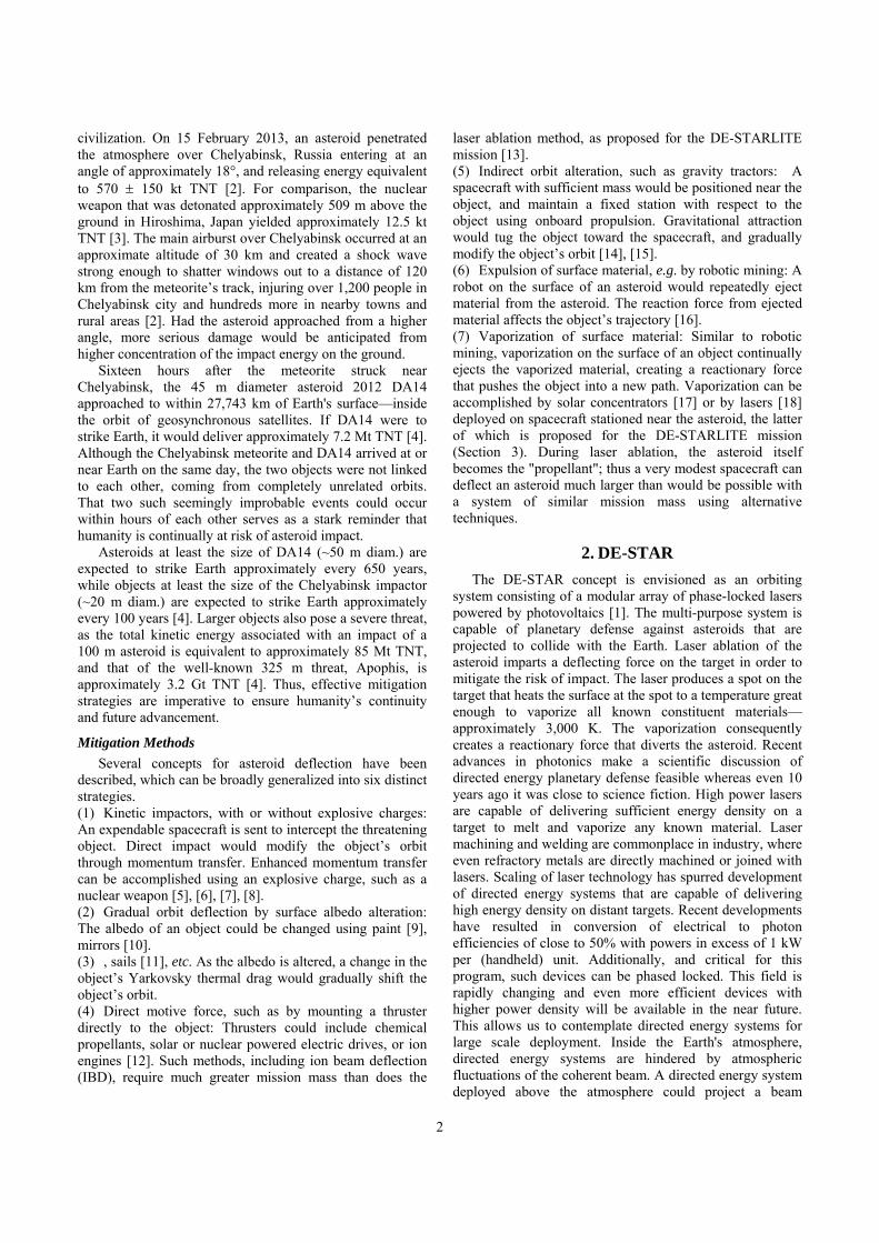
through space unfettered by atmospheric interference and thus allows us to design systems that are essentially diffraction limited as the interplanetary medium (IPM) is extremely tenuous and does not affect the laser beam significantly. The system consists of a large array of phase-locked modest power laser amplifiers. By controlling the relative phases of individual laser elements, the combined beam can be directed to a distant target. Lasers are powered by solar photovoltaics of essentially the same area as the laser array. By increasing the array size we can both reduce the spot size due to diffraction and increase the power. This dual effect allows us to vaporizing elements on the surface of asteroids at distances that are significant compared to the solar system. By raising the flux (W/m2) on the target asteroid to a sufficiently high level we can begin direct evaporation of the asteroid at the spot. This has two basic effects. Firstly, we directly begin to evaporate the asteroid and given sufficient time, a threatening asteroid could be totally vaporized before hitting the Earth. Secondly, evaporation at the spot causes a back reaction on the asteroid from the vaporization plume which acts as a rocket and thus the asteroid can be deflected. Since DE-STAR is a phased array consisting of a very large number of elements it can simultaneously be used for multiple purposes and is intrinsically a multi-tasking system. Fig. 1 depicts an orbiting DE-STAR system simultaneously engaged in both evaporating and deflecting a large asteroid as well as powering and propelling a spacecraft. The system consists of an array of phase-locked lasers. By controlling the relative phases of individual laser elements, the combined beam can be directed to a distant target. Lasers are powered by a solar panel of effectively the same area as the laser array. A DE-STAR of sufficient size would be capable of vaporizing elements on the surface of asteroids. Given sufficient time, a threatening asteroid could be vaporized, deflected or disintegrated prior to impacting Earth. The ability to direct energy onto a distant target renders DE-STAR capable of many functions. Asteroid interrogation may be possible by viewing absorption lines as the heated spot is viewed through the ejected vapor plume. Photon pressure can be used to accelerate (and decelerate) interplanetary spacecraft, among many other possibilities.
Figure 1. Left: Concept diagram of an orbiting DE-STAR engaged in multiple tasks including asteroid diversion, composition analysis and long range spacecraft power and propulsion. Right: Visualization with relevant physical phenomenon included at a flux of about 10 MW/m2. Plume density is exaggerated to show ejecta. Asteroid diameter is
about that of Apophis (325 m) relative to the laser beam diameter (30 m). Target is at 1 AU.
As this is a modular system we classify each DE-STAR
by the log of its linear size, thus a DE-STAR 1 is 10 m, DE-STAR 2 is 100 m, etc. A DE-STAR 4 system will produce a reaction thrust comparable to the Shuttle SRB on the asteroid due to mass ejection and thus allow for orbital diversion of even larger asteroids, beyond several km in diameter, thus allowing for protection from every known asteroid threat. Smaller systems are also extremely useful. For example, a DE-STAR 2 (100 m array) would be capable of diverting volatile-laden objects 100 m in diameter by initiating engagement at ~0.01-0.5 AU (AU = Astronomical Unit = mean distance from Earth to Sun ~ 1.5x10¹¹ m). Smaller objects could be diverted on shorter notice. The phased array configuration is capable of creating multiple beams, so a single DE-STAR of sufficient size could engage several threats simultaneously, such as a Shoemaker-Levy 9 scenario on Earth. An orbiting DE-STAR would also be capable of a wide variety of other functions. Narrow bandwidth and precision beam control would aid narrow search and ephemeris refinement of objects identified with wide-field surveys. Propulsion of kinetic or nuclear tipped asteroid interceptors or other interplanetary spacecraft is possible using the "photon rail gun" mode from direct photon pressure on a spacecraft, propelling (for example) a wafer scale spacecraft to c/4 in 10 minutes to reach the nearest stars in about 15 years, a 100 kg craft to 1 AU in 3 days or a 10,000 kg craft to 1 AU in 30 days. Vaporization and de-orbiting of debris in Earth orbit could be accomplished with a DE-STAR 1 or 2 system. DE-STAR 3 and 4 arrays may allow standoff interrogation of asteroid composition by observing absorption lines in the blackbody spectrum of a vaporizing surface spot. There are a number of other applications as well, including downlink power via mm, microwave or laser—the so called Space Power System mode. The system is a standoff planetary defense system that is always ready when needed and no dedicated mission is needed for each threat as is the case with other proposed mitigation methods.
3. DE-STARLITE MISSION While the larger DE-STAR system remains a long term
goal, DE-STARLITE is a more feasible and fundable mission as it is a smaller, stand-on version of the larger standoff system. DE-STARLITE is designed to be sent on a spacecraft with a 1 m to 4.5 m diameter array, to arrive nearby a Near-Earth Asteroid (NEA) and deflect it from its potentially hazardous trajectory. The laser array is essentially the same as for the DE-STAR program but vastly smaller. A secondary approach with a lower risk potential fallback is a close-packed focal plane array of fiber lasers [13]. DE-STARLITE is made possible with high-power solar electric propulsion (SEP). PV panels will be stowed for launch and will deploy upon reaching low-Earth orbit (LEO) to provide a required 100 kW electrical power from two 15 m diameter ATK MegaFlex panels. Even larger
4
power is possible within the launch mass and shroud sizes available. The system will utilize ion engines (detailed below) to propel the spacecraft from LEO to an NEA, as proposed in JPL’s ARM program [13]. The system aims to stay within the same mass and launch constraints as ARM and use much of the same propulsion technology. The laser efficiency determines the laser power obtained from the PV arrays; 35 kW of laser power would be produced at 35% efficiency, 50 kW at 50%, and 70 kW at 70%. The 35 kW estimate is based on the current efficiency (35%) of existing technology of the baseline Ytterbium laser amplifiers and thus provides for the worst case, while the 50 and 70 kW estimates are based on feasible technological improvement within the next 5-15 years. For example, 50% efficiency looks readily achievable within less than 5 years. A passive cooling radiator with z-folded arrays will be used to reject waste heat and maintain the temperature at near 300 K. Conceptual drawings of the system and payload are shown in Fig. 2 and Fig 3.
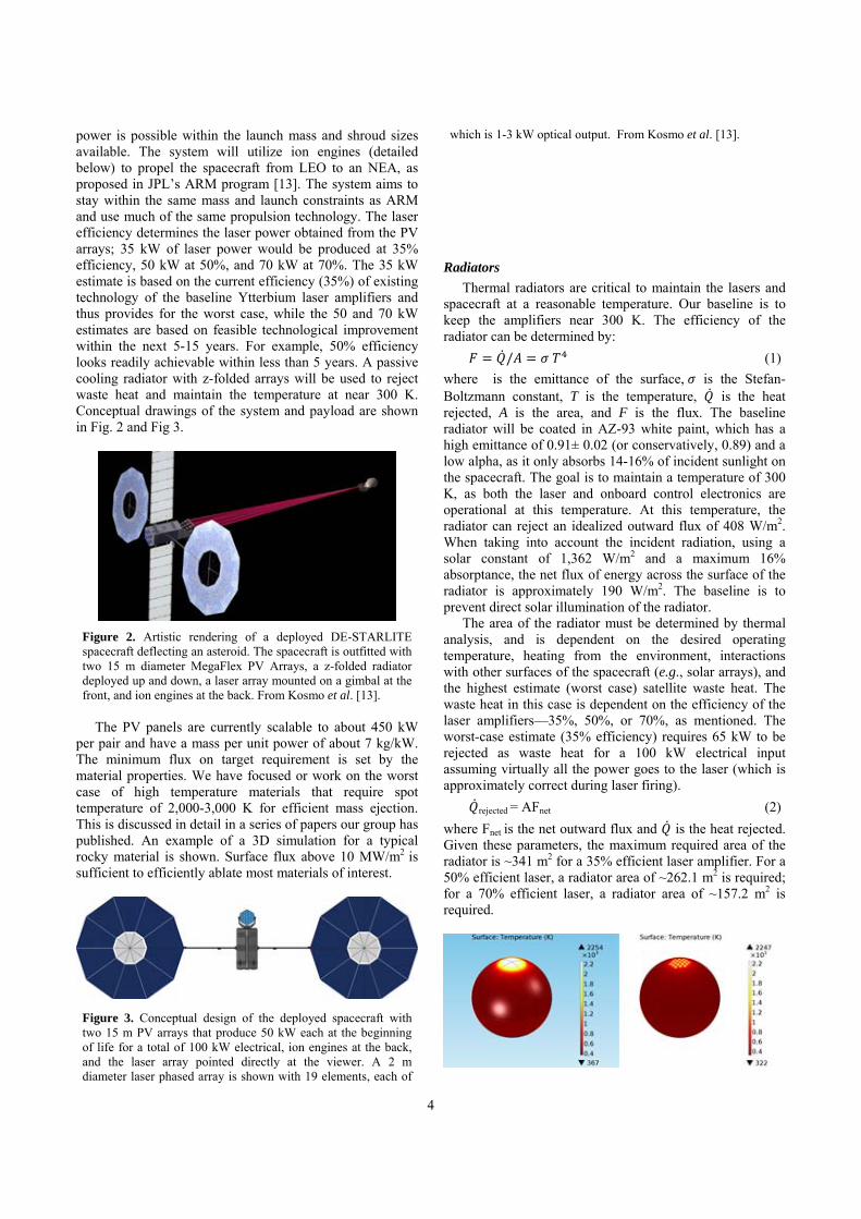
Figure 2. Artistic rendering of a deployed DE-STARLITE spacecraft deflecting an asteroid. The spacecraft is outfitted with two 15 m diameter MegaFlex PV Arrays, a z-folded radiator deployed up and down, a laser array mounted on a gimbal at the front, and ion engines at the back. From Kosmo et al. [13].
The PV panels are currently scalable to about 450 kW
per pair and have a mass per unit power of about 7 kg/kW. The minimum flux on target requirement is set by the material properties. We have focused or work on the worst case of high temperature materials that require spot temperature of 2,000-3,000 K for efficient mass ejection. This is discussed in detail in a series of papers our group has published. An example of a 3D simulation for a typical rocky material is shown. Surface flux above 10 MW/m2 is sufficient to efficiently ablate most materials of interest.
Figure 3. Conceptual design of the deployed spacecraft with two 15 m PV arrays that produce 50 kW each at the beginning of life for a total of 100 kW electrical, ion engines at the back, and the laser array pointed directly at the viewer. A 2 m diameter laser phased array is shown with 19 elements, each of
which is 1-3 kW optical output. From Kosmo et al. [13].
Radiators Thermal radiators are critical to maintain the lasers and
spacecraft at a reasonable temperature. Our baseline is to keep the amplifiers near 300 K. The efficiency of the radiator can be determined by:
/ (1) where is the emittance of the surface, is the Stefan-Boltzmann constant, T is the temperature, is the heat rejected, A is the area, and F is the flux. The baseline radiator will be coated in AZ-93 white paint, which has a high emittance of 0.91± 0.02 (or conservatively, 0.89) and a low alpha, as it only absorbs 14-16% of incident sunlight on the spacecraft. The goal is to maintain a temperature of 300 K, as both the laser and onboard control electronics are operational at this temperature. At this temperature, the radiator can reject an idealized outward flux of 408 W/m2. When taking into account the incident radiation, using a solar constant of 1,362 W/m2 and a maximum 16% absorptance, the net flux of energy across the surface of the radiator is approximately 190 W/m2. The baseline is to prevent direct solar illumination of the radiator.
The area of the radiator must be determined by thermal analysis, and is dependent on the desired operating temperature, heating from the environment, interactions with other surfaces of the spacecraft (e.g., solar arrays), and the highest estimate (worst case) satellite waste heat. The waste heat in this case is dependent on the efficiency of the laser amplifiers—35%, 50%, or 70%, as mentioned. The worst-case estimate (35% efficiency) requires 65 kW to be rejected as waste heat for a 100 kW electrical input assuming virtually all the power goes to the laser (which is approximately correct during laser firing).
rejected = AFnet (2) where Fnet is the net outward flux and is the heat rejected. Given these parameters, the maximum required area of the radiator is ~341 m2 for a 35% efficient laser amplifier. For a 50% efficient laser, a radiator area of ~262.1 m2 is required; for a 70% efficient laser, a radiator area of ~157.2 m2 is required.
5
Figure 4. Left: Simulation showing one spot from the baseline phased array on the target at sufficient temperature to cause ablation. Right: Multi-beam simulation depicting 19 beams on the target from an optional choice of a close packed laser array instead of a phased array.
A passive cooling z-folded radiator consisting of two deployable panels will be used in order to provide a sufficient surface area over which to emit the waste heat generated by the system. Each panel z-folds out into six segments, each of which further folds out into two additional segments, making 18 segments in total for each panel. The panels will rotate about their axes to maximize efficiency by remaining perpendicular to the sun and by radiating out of both sides. Each segment will be 2.2 m by 2.2 m, granting a total area of 348 m2 out of which to dissipate heat. This will provide sufficient surface area to reject the maximum projected waste heat. If by the time of production, significant increases in laser efficiency have indeed been reached, the size of the panels can be altered so as to reduce the excess mass if less heat needs to be dissipated. Sun shades may also be employed to limit solar absorption and thus allow for greater efficiency. The current mass to power ratio for radiators is about 25 kg/kW for the ARM system as a baseline example. Radiators are currently the largest mass driver for large systems. This is an area that needs additional work, though even with the existing radiator designs, MW-class systems are feasible with current (or soon to exist) launchers. More laser amplifiers are easily added to allow for scaling to larger power levels. A 1 m to 4.5 m diameter is feasible; no additional deflection comes from the larger optic, just additional range from the target.
Launch Systems The launch systems in consideration are Atlas V 551,
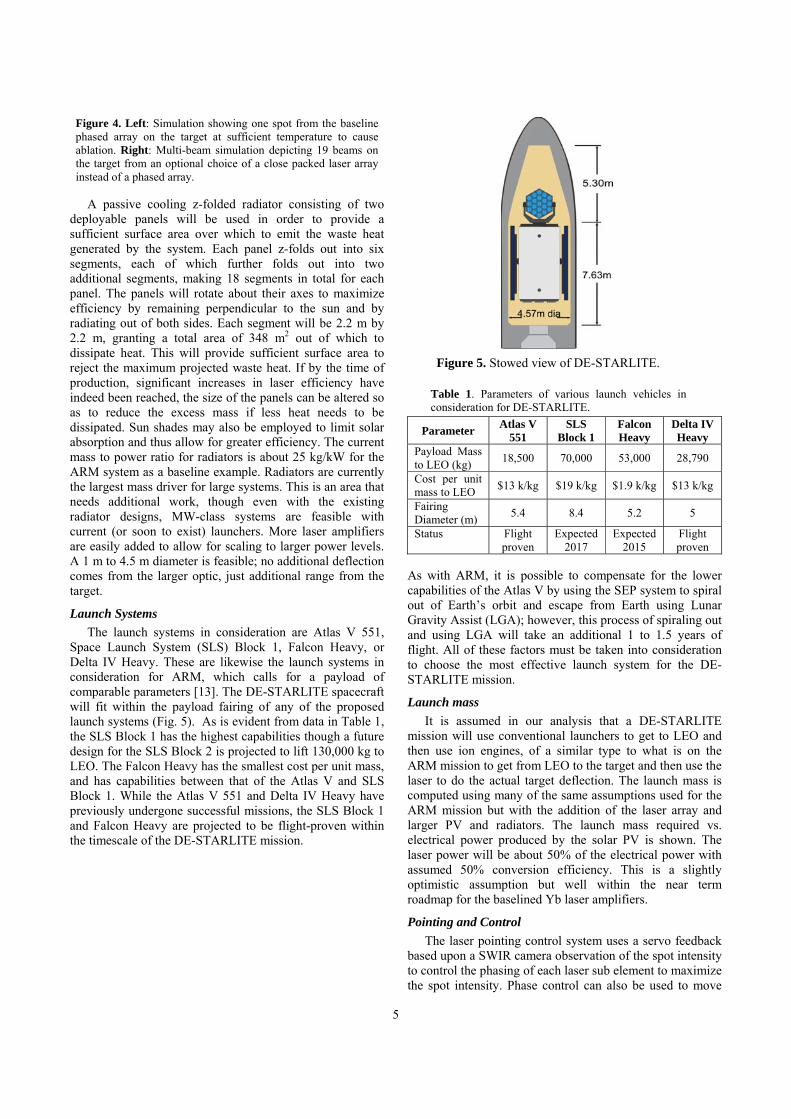
Space Launch System (SLS) Block 1, Falcon Heavy, or Delta IV Heavy. These are likewise the launch systems in consideration for ARM, which calls for a payload of comparable parameters [13]. The DE-STARLITE spacecraft will fit within the payload fairing of any of the proposed launch systems (Fig. 5). As is evident from data in Table 1, the SLS Block 1 has the highest capabilities though a future design for the SLS Block 2 is projected to lift 130,000 kg to LEO. The Falcon Heavy has the smallest cost per unit mass, and has capabilities between that of the Atlas V and SLS Block 1. While the Atlas V 551 and Delta IV Heavy have previously undergone successful missions, the SLS Block 1 and Falcon Heavy are projected to be flight-proven within the timescale of the DE-STARLITE mission.
Figure 5. Stowed view of DE-STARLITE.
Table 1. Parameters of various launch vehicles in consideration for DE-STARLITE.
Parameter Atlas V 551
SLS Block 1
Falcon Heavy
Delta IV Heavy
Payload Mass to LEO (kg) 18,500 70,000 53,000 28,790
Cost per unit mass to LEO $13 k/kg $19 k/kg $1.9 k/kg $13 k/kg
Fairing Diameter (m) 5.4 8.4 5.2 5
Status Flight proven
Expected 2017
Expected 2015
Flight proven
As with ARM, it is possible to compensate for the lower capabilities of the Atlas V by using the SEP system to spiral out of Earth’s orbit and escape from Earth using Lunar Gravity Assist (LGA); however, this process of spiraling out and using LGA will take an additional 1 to 1.5 years of flight. All of these factors must be taken into consideration to choose the most effective launch system for the DE-STARLITE mission.
Launch mass It is assumed in our analysis that a DE-STARLITE
mission will use conventional launchers to get to LEO and then use ion engines, of a similar type to what is on the ARM mission to get from LEO to the target and then use the laser to do the actual target deflection. The launch mass is computed using many of the same assumptions used for the ARM mission but with the addition of the laser array and larger PV and radiators. The launch mass required vs. electrical power produced by the solar PV is shown. The laser power will be about 50% of the electrical power with assumed 50% conversion efficiency. This is a slightly optimistic assumption but well within the near term roadmap for the baselined Yb laser amplifiers.
Pointing and Control The laser pointing control system uses a servo feedback
based upon a SWIR camera observation of the spot intensity to control the phasing of each laser sub element to maximize the spot intensity. Phase control can also be used to move
the spot as neby the gimbattitude contro
4. ORB
This sectiapplied thrustexposed to thand flux (Wsufficiently hoccur, targetinflux of >107 asteroid at thproduces a vachange the asfrom collidinEarth radii (1collision. Themagnitude, an
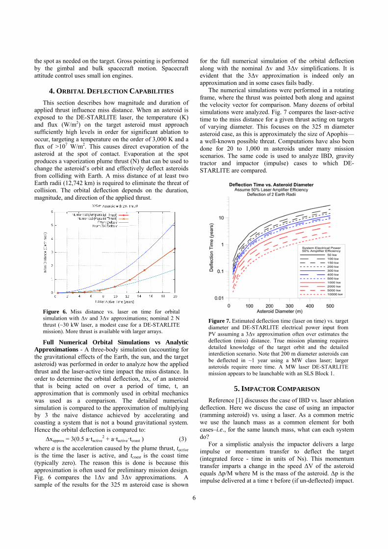
Figure 6. simulation thrust (~30mission). M
Full NumApproximatithe gravitatioasteroid) was thrust and theorder to deterthat is beingapproximationwas used asimulation is by 3 the nacoasting a syHence the orb
∆xapprox =where a is theis the time th(typically zerapproximationFig. 6 compsample of the
eeded on the tabal and bulkol uses small
BITAL DEFL
ion describes t influence mhe DE-STAR
W/m2) on thehigh levels in ng a temperatW/m2. This
he spot of caporization plusteroid’s orbit
ng with Earth.2,742 km) is e orbital deflnd direction o
Miss distancewith Δv and 3
0 kW laser, a mMore thrust is av
merical Orbions - A threenal effects of performed in
e laser-active rmine the orbg acted on n that is comas a compacompared to
aive distanceystem that is nbital deflection= 3(0.5 a·tactive
e accelerationhe laser is acro). The reasn is often use
pares the 1Δve results for t
arget. Gross pk spacecraft ion engines.
LECTION CA
how magnitumiss distance. WRLITE laser, t
target asterorder for sig
ture on the ordcauses direct
contact. Evapume thrust (Nt and effectiv. A miss distarequired to ellection depenf the applied t
e vs. laser onΔv approximat
modest case forvailable with la
bital Simulae-body simulaf the Earth, then order to analtime impact t
bital deflectionover a peri
mmonly used iarison. The
the approxime achieved bnot a bound gn is compared2 + a·tactive·tcoa
n caused by thctive, and tcoason this is doed for preliminv and 3Δv athe 325 m ast
pointing is perfmotion. Spa
APABILITIE
ude and duraWhen an astethe temperaturoid must apgnificant ablader of 3,000 Kt evaporation
poration at thN) that can be u
ely deflect asance of at lealiminate the thnds on the duthrust.
n time for orbtions; nominal r a DE-STARLarger arrays.
ations vs Anation (accounte sun, and thelyze how the athe miss distan, ∆x, of an aiod of time, in orbital mecdetailed num
mation of multby acceleratingravitational sd to: ast )
he plume thrusast is the coasone is becaunary mission dapproximationteroid case is
6
formed acecraft
S tion of
eroid is ure (K) pproach ation to K and a
of the he spot used to steroids ast two hreat of uration,
bital 2 N
LITE
nalytic ting for e target applied
ance. In asteroid
t, an chanics merical iplying
ng and system.
(3) st, tactive st time
use this design. ns. A shown
foaloevap
frathsimtimofasa dosctraST
de(rawecado
im(intraeqim
or the full nuong with the
vident that thpproximation a
The numericame, where th
he velocity vecmulations werme to the misf varying diamsteroid case, awell-known p
one for 20 tcenarios. The actor and imTARLITE are
Figure 7. Estdiameter andPV assumingdeflection (mdetailed knowinterdiction scbe deflected asteroids requmission appea
5.Reference [1
eflection. Heramming astere use the lau
ases–i.e., for to?
For a simplmpulse or mntegrated forcansfer impartsquals Δp/M wmpulse deliver
umerical simunominal Δv
he 3Δv apprand in some ccal simulationhe thrust was ctor for compre analyzed. Fs distance for meter. This fos this is appro
possible threato 1,000 m asame code is
mpactor (impe compared.
timated deflectid DE-STARLITg a 3Δv approxmiss) distance. wledge of thecenario. Note thin ~1 year u
uire more timears to be launch
. IMPACTOR
1] discusses thre we discuss roid) vs. usingunch mass asthe same laun
listic analysismomentum trce - time in s a change in
where M is thered at a time τ
ulation of the and 3Δv sim
roximation iscases fails badns were perfopointed both
parison. ManyFig. 7 comparr a given thrusfocuses on theoximately the t. Computatioasteroids unds used to ana
mpulse) cases
ion time (laser oTE electrical p
ximation often oTrue mission
e target orbit hat 200 m diam
using a MW ce. A MW lasehable with an S
R COMPARI
he case of IBDthe case of u
g a laser. As s a common
nch mass, wha
s the impactoransfer to dunits of Ns).
n the speed Δe mass of the
before (if un-
orbital deflemplifications. s indeed onlydly. rmed in a rotalong and ag
y dozens of orres the laser-ast acting on tae 325 m diamsize of Apoph
ons have also der many mialyze IBD, gr to which
on time) vs. tarpower input frover estimates planning requiand the detai
meter asteroids cclass laser; larer DE-STARLILS Block 1.
ISON D vs. laser ablusing an impa common melement for
at can each sy
or delivers a deflect the t. This momenΔV of the astasteroid. Δp i-deflected) im
ection It is
y an
tating gainst rbital
active argets meter his—been ssion
ravity DE-
rget om the ires iled can ger
ITE
lation actor
metric both
ystem
large target ntum eroid is the
mpact.
7
The term Δp equals mv where m is the spacecraft mass and v is the relative closing speed between the spacecraft and asteroid. The change of speed is thus
ΔV = mv/M = v(m/M) (4) The deflection distance at the Earth is approximately
Δx = 3 ΔV·τ = 3·v·τ (m/M) (5) where the factor of 3 is an approximation used from orbital dynamics but as we have shown in several of our papers it is not always a good approximation. We use it here for illustrative purposes and because it is often used in mission planetary defense planning exercises.
Note that the miss distance Δx is linearly proportional to the spacecraft mass (m), the closing speed (v) and time to impact τ and inversely proportional to the asteroid mass M. Note that the asteroid mass M is proportional to the cube of the asteroid diameter D. The momentum change (impulse delivered) is largely independent of the asteroid mass and only depends on the spacecraft mass (m) and the closing speed (v). For a homogeneous asteroid of density ρ then miss distance is:
Δx = 3 ΔV·τ = 18·m·v·τ / (πρD3) (6) Since the asteroid is moving rapidly with typical speeds of 5-40 km/s we can simplify this to assume the spacecraft is simply in the way of the asteroid (inelastic billiard ball) and thus the speed of the spacecraft relation to the earth is of lesser importance. This of course depends on the specifics of the asteroid orbit (closing from the front vs. the back of the asteroid orbit). Essentially then it is the mass of the spacecraft that is critical to maximize. Once the space craft is launched to LEO it is assumed that ion engines will be used to allow a larger fraction of the launch mass to survive until impact to maximize the impulse. Since the miss distance is proportional to the inverse cube of the asteroid diameter, and the spacecraft mass is limited by the launcher capability, the only free parameter is the time to impact τ. Thus the miss distance is:
Δx = 3·ΔV·τ = 3·Δp/M·τ = 18·m·v·τ/(πρD3) (7) In other words, the miss distance is proportional to:
Δx ~ m·v·τ·D-3 (8) For the case of directed energy the equivalent miss distance (using the same factor of 3 approximation for the effects of orbital mechanics) is:
Δx =3·1/2·a·τ2 = 3/2 (a·τ) τ = 3/2 ΔV·τ = 3/2 (F/M) τ2
=3/2 F·τ2/M = 1/2·3·Δp/M·τ = 9 α P·τ2/(πρD3 ) (9) where:
a = acceleration imparted due to the laser plume thrust F = laser plume thrust = α P P = laser power α = laser plume thrust coupling coefficient M = asteroid mass = πρD3/6
We assume the laser thrust is constant and the asteroid mass changes very little due to the mass loss from ablation and that the laser plume thrust is proportional to the laser power. See our other papers on the detailed modeling for this. For simplicity we assume α ~ 80 µN/W optical in central spot. Note that for the case of directed energy or any constant
force (such as ion engines, gravity tractors, etc.) the miss distance:
Δxlaser = 1/2·3·Δp/M·τ (10) while for the impulse delivery (effectively instantaneously at a time τ before impact) for the same overall delta momentum delivered to the asteroid is:
Δximpactor = 3·Δp/M·τ, or: Δxlaser = 1/2 Δximpactor (11)
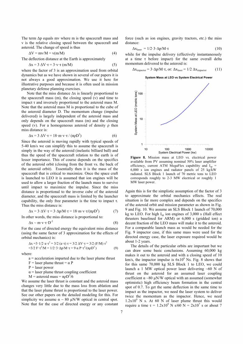
Figure 8. Mission mass at LEO vs. electrical power available from PV assuming nominal 50% laser amplifier efficiency, current ATM MegaFlex capability and Isp = 6,000 s ion engines and radiator panels of 25 kg/kW radiated. SLS Block 1 launch of 70 metric tons to LEO corresponds roughly to 2-3 MW electrical or roughly 1 MW laser power.
Again this is for the simplistic assumption of the factor of 3 to approximate the orbital mechanics effects. The real situation is far more complex and depends on the specifics of the asteroid orbit and mission parameter as shown in Fig. 9 and Fig. 10. We assume an SLS Block 1 launch of 70,000 kg to LEO. For high Isp ion engines of 3,000 s (Hall effect thrusters baselined for ARM) or 6,000 s (gridded ion) a decent fraction of the LEO mass will make it to the asteroid. For a comparable launch mass as would be needed for the Fig. 9 impactor case, if this same mass were used for the directed energy case, the laser exposure required would be about 1-2 years.
The details of the particular orbits are important but we can draw some basic conclusions. Assuming 60,000 kg makes it out to the asteroid and with a closing speed of 10 km/s, the impactor impulse is 6x10⁸ Ns. Fig. 8 shows that for this same 70,000 kg SLS Block 1 to LEO, we could launch a 1 MW optical power laser delivering ~60 N of thrust on the asteroid for an assumed laser coupling coefficient α ~80 µN/W optical with an assumed (somewhat optimistic) high efficiency beam formation in the central spot of 0.7. To get the same deflection in the same time to impact as the impactor, we need the laser system to deliver twice the momentum as the impactor. Hence, we need 1.2x10⁹ N s. At 60 N of laser plume thrust this would require a time τ = 1.2x10⁹ N s/60 N = 2x10⁷ s or about 7
8
months. In this case, the exposure time needed is about 7 months. This time is independent of the launch mass as both the impactor momentum delivered and the laser momentum are proportional to launch mass for reasonably large launch masses. Other differences for real systems are typical impactor missions need more than one to make sure the impulse was delivered properly. For any real threat, multiple backups would be prudent.
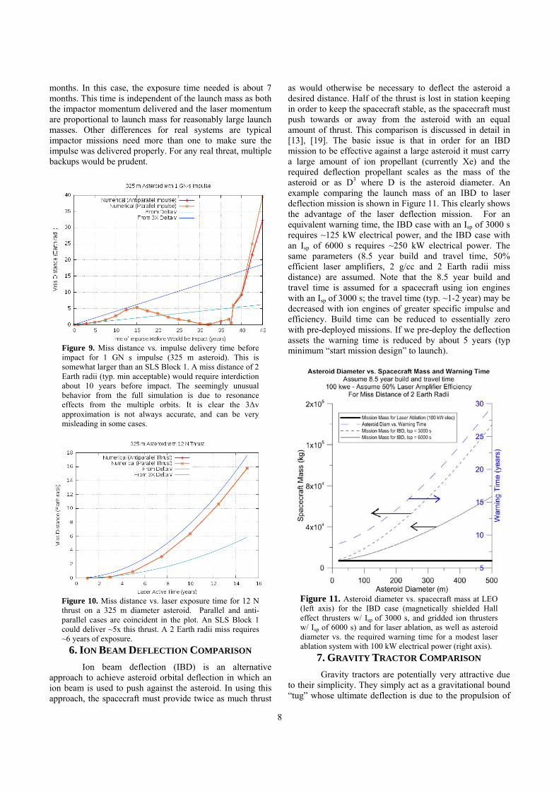
Figure 9. Miss distance vs. impulse delivery time before impact for 1 GN s impulse (325 m asteroid). This is somewhat larger than an SLS Block 1. A miss distance of 2 Earth radii (typ. min acceptable) would require interdiction about 10 years before impact. The seemingly unusual behavior from the full simulation is due to resonance effects from the multiple orbits. It is clear the 3Δv approximation is not always accurate, and can be very misleading in some cases.
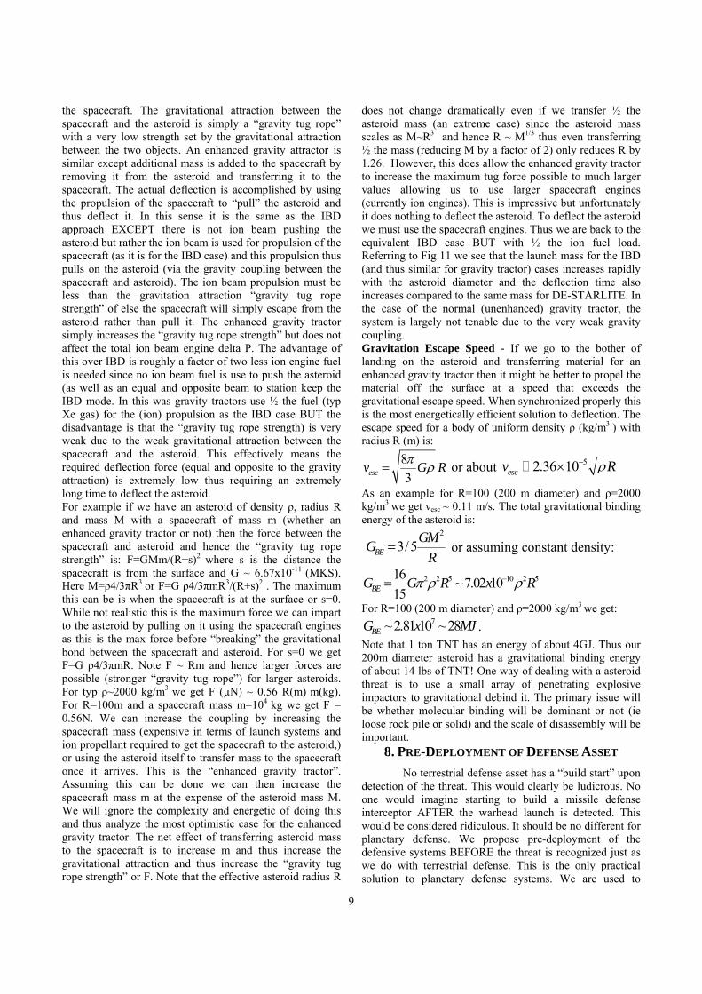
Figure 10. Miss distance vs. laser exposure time for 12 N thrust on a 325 m diameter asteroid. Parallel and anti-parallel cases are coincident in the plot. An SLS Block 1 could deliver ~5x this thrust. A 2 Earth radii miss requires ~6 years of exposure.
6. ION BEAM DEFLECTION COMPARISON Ion beam deflection (IBD) is an alternative
approach to achieve asteroid orbital deflection in which an ion beam is used to push against the asteroid. In using this approach, the spacecraft must provide twice as much thrust
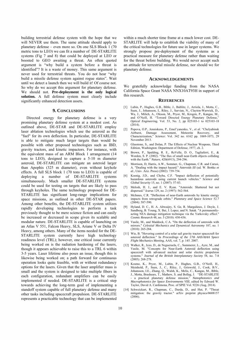
as would otherwise be necessary to deflect the asteroid a desired distance. Half of the thrust is lost in station keeping in order to keep the spacecraft stable, as the spacecraft must push towards or away from the asteroid with an equal amount of thrust. This comparison is discussed in detail in [13], [19]. The basic issue is that in order for an IBD mission to be effective against a large asteroid it must carry a large amount of ion propellant (currently Xe) and the required deflection propellant scales as the mass of the asteroid or as D3 where D is the asteroid diameter. An example comparing the launch mass of an IBD to laser deflection mission is shown in Figure 11. This clearly shows the advantage of the laser deflection mission. For an equivalent warning time, the IBD case with an Isp of 3000 s requires ~125 kW electrical power, and the IBD case with an Isp of 6000 s requires ~250 kW electrical power. The same parameters (8.5 year build and travel time, 50% efficient laser amplifiers, 2 g/cc and 2 Earth radii miss distance) are assumed. Note that the 8.5 year build and travel time is assumed for a spacecraft using ion engines with an Isp of 3000 s; the travel time (typ. ~1-2 year) may be decreased with ion engines of greater specific impulse and efficiency. Build time can be reduced to essentially zero with pre-deployed missions. If we pre-deploy the deflection assets the warning time is reduced by about 5 years (typ minimum “start mission design” to launch).
Figure 11. Asteroid diameter vs. spacecraft mass at LEO (left axis) for the IBD case (magnetically shielded Hall effect thrusters w/ Isp of 3000 s, and gridded ion thrusters w/ Isp of 6000 s) and for laser ablation, as well as asteroid diameter vs. the required warning time for a modest laser ablation system with 100 kW electrical power (right axis).
7. GRAVITY TRACTOR COMPARISON Gravity tractors are potentially very attractive due to their simplicity. They simply act as a gravitational bound “tug” whose ultimate deflection is due to the propulsion of
9
the spacecraft. The gravitational attraction between the spacecraft and the asteroid is simply a “gravity tug rope” with a very low strength set by the gravitational attraction between the two objects. An enhanced gravity attractor is similar except additional mass is added to the spacecraft by removing it from the asteroid and transferring it to the spacecraft. The actual deflection is accomplished by using the propulsion of the spacecraft to “pull” the asteroid and thus deflect it. In this sense it is the same as the IBD approach EXCEPT there is not ion beam pushing the asteroid but rather the ion beam is used for propulsion of the spacecraft (as it is for the IBD case) and this propulsion thus pulls on the asteroid (via the gravity coupling between the spacecraft and asteroid). The ion beam propulsion must be less than the gravitation attraction “gravity tug rope strength” of else the spacecraft will simply escape from the asteroid rather than pull it. The enhanced gravity tractor simply increases the “gravity tug rope strength” but does not affect the total ion beam engine delta P. The advantage of this over IBD is roughly a factor of two less ion engine fuel is needed since no ion beam fuel is use to push the asteroid (as well as an equal and opposite beam to station keep the IBD mode. In this was gravity tractors use ½ the fuel (typ Xe gas) for the (ion) propulsion as the IBD case BUT the disadvantage is that the “gravity tug rope strength) is very weak due to the weak gravitational attraction between the spacecraft and the asteroid. This effectively means the required deflection force (equal and opposite to the gravity attraction) is extremely low thus requiring an extremely long time to deflect the asteroid. For example if we have an asteroid of density ρ, radius R and mass M with a spacecraft of mass m (whether an enhanced gravity tractor or not) then the force between the spacecraft and asteroid and hence the “gravity tug rope strength” is: F=GMm/(R+s)2 where s is the distance the spacecraft is from the surface and G ~ 6.67x10⁻¹¹ (MKS). Here M=ρ4/3πR3 or F=G ρ4/3πmR3/(R+s)2 . The maximum this can be is when the spacecraft is at the surface or s=0. While not realistic this is the maximum force we can impart to the asteroid by pulling on it using the spacecraft engines as this is the max force before “breaking” the gravitational bond between the spacecraft and asteroid. For s=0 we get F=G ρ4/3πmR. Note F ~ Rm and hence larger forces are possible (stronger “gravity tug rope”) for larger asteroids. For typ ρ~2000 kg/m3 we get F (µN) ~ 0.56 R(m) m(kg). For R=100m and a spacecraft mass m=104 kg we get F = 0.56N. We can increase the coupling by increasing the spacecraft mass (expensive in terms of launch systems and ion propellant required to get the spacecraft to the asteroid,) or using the asteroid itself to transfer mass to the spacecraft once it arrives. This is the “enhanced gravity tractor”. Assuming this can be done we can then increase the spacecraft mass m at the expense of the asteroid mass M. We will ignore the complexity and energetic of doing this and thus analyze the most optimistic case for the enhanced gravity tractor. The net effect of transferring asteroid mass to the spacecraft is to increase m and thus increase the gravitational attraction and thus increase the “gravity tug rope strength” or F. Note that the effective asteroid radius R
does not change dramatically even if we transfer ½ the asteroid mass (an extreme case) since the asteroid mass scales as M~R3 and hence R ~ M1/3 thus even transferring ½ the mass (reducing M by a factor of 2) only reduces R by 1.26. However, this does allow the enhanced gravity tractor to increase the maximum tug force possible to much larger values allowing us to use larger spacecraft engines (currently ion engines). This is impressive but unfortunately it does nothing to deflect the asteroid. To deflect the asteroid we must use the spacecraft engines. Thus we are back to the equivalent IBD case BUT with ½ the ion fuel load. Referring to Fig 11 we see that the launch mass for the IBD (and thus similar for gravity tractor) cases increases rapidly with the asteroid diameter and the deflection time also increases compared to the same mass for DE-STARLITE. In the case of the normal (unenhanced) gravity tractor, the system is largely not tenable due to the very weak gravity coupling. Gravitation Escape Speed - If we go to the bother of landing on the asteroid and transferring material for an enhanced gravity tractor then it might be better to propel the material off the surface at a speed that exceeds the gravitational escape speed. When synchronized properly this is the most energetically efficient solution to deflection. The escape speed for a body of uniform density ρ (kg/m3 ) with radius R (m) is:
83escv G Rπ ρ= or about 52.36 10escv Rρ−×
As an example for R=100 (200 m diameter) and ρ=2000 kg/m3 we get νesc ~ 0.11 m/s. The total gravitational binding energy of the asteroid is:
2
3/5BEGMG
R= or assuming constant density:
2 2 5102 5 ~7.02 1161
05BEG G R Rxπ ρ ρ−=
For R=100 (200 m diameter) and ρ=2000 kg/m3 we get: 72.81 1 ~28~ 0BEG x MJ .
Note that 1 ton TNT has an energy of about 4GJ. Thus our 200m diameter asteroid has a gravitational binding energy of about 14 lbs of TNT! One way of dealing with a asteroid threat is to use a small array of penetrating explosive impactors to gravitational debind it. The primary issue will be whether molecular binding will be dominant or not (ie loose rock pile or solid) and the scale of disassembly will be important.
8. PRE-DEPLOYMENT OF DEFENSE ASSET No terrestrial defense asset has a “build start” upon detection of the threat. This would clearly be ludicrous. No one would imagine starting to build a missile defense interceptor AFTER the warhead launch is detected. This would be considered ridiculous. It should be no different for planetary defense. We propose pre-deployment of the defensive systems BEFORE the threat is recognized just as we do with terrestrial defense. This is the only practical solution to planetary defense systems. We are used to
10
building terrestrial defense system with the hope that we will NEVER use them. The same attitude should apply to planetary defense – even more so. On one SLS Block 1 (70 metric tons to LEO) we can fit a number of DE-STARLITE systems (Fig 7 and 8) that could be deployed at LEO or boosted to GEO awaiting a threat. An often quoted argument is “why build a system before a threat is identified”? It is a waste of money. This same argument is never used for terrestrial threats. You do not hear “why build a missile defense system against rogue states”. Wait until we detect a launch then we will build it! Of course not. So why do we accept this argument for planetary defense. We should not. Pre-deployment is the only logical solution. A full defense system must clearly include significantly enhanced detection assets.
9. CONCLUSIONS
Directed energy for planetary defense is a very promising planetary defense system at a modest cost. As outlined above, DE-STAR and DE-STARLITE employ laser ablation technologies which use the asteroid as the "fuel" for its own deflection. In particular, DE-STARLITE is able to mitigate much larger targets than would be possible with other proposed technologies such as IBD, gravity tractors, and kinetic impactors. For instance, with the equivalent mass of an ARM Block 1 arrangement (14 tons to LEO), designed to capture a 5-10 m diameter asteroid, DE-STARLITE can mitigate an asteroid larger than Apophis (325 m diameter), even without keyhole effects. A full SLS block 1 (70 tons to LEO) is capable of deploying a number of DE-STARLITE systems simultaneously. Much smaller DE-STARLITE systems could be used for testing on targets that are likely to pass through keyholes. The same technology proposed for DE-STARLITE has significant long-range implications for space missions, as outlined in other DE-STAR papers. Among other benefits, the DE-STARLITE system utilizes rapidly developing technologies to perform a task previously thought to be mere science fiction and can easily be increased or decreased in scope given its scalable and modular nature. DE-STARLITE is capable of launching on an Atlas V 551, Falcon Heavy, SLS, Ariane V or Delta IV Heavy, among others. Many of the items needed for the DE-STARLITE system currently have high technology readiness level (TRL); however, one critical issue currently being worked on is the radiation hardening of the lasers, though it appears achievable to raise this to a TRL 6 within 3-5 years. Laser lifetime also poses an issue, though this is likewise being worked on; a path forward for continuous operation looks quite feasible, with or without redundancy options for the lasers. Given that the laser amplifier mass is small and the system is designed to take multiple fibers in each configuration, redundant amplifiers can be easily implemented if needed. DE-STARLITE is a critical step towards achieving the long-term goal of implementing a standoff system capable of full planetary defense and many other tasks including spacecraft propulsion. DE-STARLITE represents a practicable technology that can be implemented
within a much shorter time frame at a much lower cost. DE-STARLITE will help to establish the viability of many of the critical technologies for future use in larger systems. We strongly propose pre-deployment of the systems as a practical measure for planetary defense rather than waiting for the threat before building. We would never accept such an attitude for terrestrial missile defense, nor should we for planetary defense.
ACKNOWLEDGEMENTS We gratefully acknowledge funding from the NASA California Space Grant NASA NNX10AT93H in support of this research.
REFERENCES [1] Lubin, P., Hughes, G.B., Bible, J., Bublitz, J., Arriola, J., Motta, C.,
Suen, J., Johansson, I., Riley, J., Sarvian, N., Clayton-Warwick, D., Wu, J., Milich, A., Oleson, M., Pryor, M., Krogen, P., Kangas, M., and O’Neill, H. “Toward Directed Energy Planetary Defense,” Optical Engineering, Vol. 53, No. 2, pp 025103-1 to 025103-18 (2014).
[2] Popova, O.P., Jenniskens, P., Emel’yanenko, V., et al. “Chelyabinsk Airburst, Damage Assessment, Meteorite Recovery, and Characterization,” Science: Vol. 342 no. 6162 pp. 1069-1073, 29 November 2013.
[3] Glasstone, S., and Dolan, P. The Effects of Nuclear Weapons, Third Edition, Washington: Department of Defense, 1977, ch. 2.
[4] Brown, P., Spalding, R. E., ReVelle, D. O., Tagliaferri, E., & Worden, S. P. (2002). “The flux of small near-Earth objects colliding with the Earth.” Nature, 420(6913), 294-296.
[5] Morrison, D, Harris, A.W., Sommer, G., Chapman, C.R. and Carusi, A. "Dealing with the impact hazard." Asteroids III (ed. W. Bottke et al., Univ. Ariz. Press) (2002): 739-754.
[6] Koenig, J.D., and Chyba, C.F. "Impact deflection of potentially hazardous asteroids using current launch vehicles." Science and Global Security 15, no. 1 (2007): 57-83.
[7] Melosh, H. J., and E. V. Ryan. "Asteroids: Shattered but not dispersed." Icarus 129, no. 2 (1997): 562-564.
[8] McInnes, C.R. "Deflection of near-Earth asteroids by kinetic energy impacts from retrograde orbits." Planetary and Space Science 52.7 (2004): 587-590.
[9] Hyland, D. C., H. A. Altwaijry, S. Ge, R. Margulieux, J. Doyle, J. Sandberg, B. Young, X. Bai, J. Lopez, and N. Satak. "A permanently-acting NEA damage mitigation technique via the Yarkovsky effect." Cosmic Research 48, no. 5 (2010): 430-436.
[10] Vasile, M., and Maddock, C.A. "On the deflection of asteroids with mirrors." Celestial Mechanics and Dynamical Astronomy 107, no. 1 (2010): 265-284.
[11] Wie, B. "Hovering control of a solar sail gravity tractor spacecraft for asteroid deflection." In Proceedings of the 17th AAS/AIAA Space Flight Mechanics Meeting, AAS, vol. 7, p. 145. 2007.
[12] Walker, R., Izzo, D., de Negueruela, C., Summerer, L., Ayre, M., and Vasile, M. "Concepts for Near-Earth Asteroid deflection using spacecraft with advanced nuclear and solar electric propulsion systems." Journal of the British Interplanetary Society 58, no. 7-8 (2005): 268-278.
[13] Kosmo, K., Pryor, M., Lubin, P., Hughes, G.B., O’Neill, H., Meinhold, P., Suen, J., C., Riley, J., Griswold, J., Cook, B.V., Johansson, I.E., Zhang, Q., Walsh, K., Melis, C., Kangas, M., Bible, J., Motta, Brashears, T., Mathew, S. and Bollag, J. “DE-STARLITE - a practical planetary defense mission,” Nanophotonics and Macrophotonics for Space Environments VIII, edited by Edward W. Taylor, David A. Cardimona, Proc. of SPIE Vol. 9226 (Aug, 2014).
[14] Schweickart, R., Chapman, C., Durda, D., and Hut, P. "Threat mitigation: the gravity tractor." arXiv preprint physics/0608157 (2006).
11
[15] Lu, E.T., and Love, S.G. "A gravitational tractor for towing asteroids." arXiv preprint astro-ph/0509595 (2005).
[16] Olds, J., Charania, A., & Schaffer, M. G. (2007, March). “Multiple mass drivers as an option for asteroid deflection missions.” In 2007 Planetary Defense Conference, Washington, DC, Paper (pp. S3-7).
[17] Gibbings, M. A., Hopkins, J. M., Burns, D., & Vasile, M. (2011). “On Testing Laser Ablation Processes for Asteroid Deflection,” 2011 IAA Planetary Defense Conference, Bucharest, Romania.
[18] Maddock, C, Cuartielles, J.P.S., Vasile, M. and Radice, G. "Comparison of Single and Multi‐Spacecraft Configurations for NEA Deflection by Solar Sublimation." In AIP Conference Proceedings, vol. 886, p. 303. 200
[19] Lubin, P., Hughes, G.B., Kosmo, K., Johansson, I.E., Griswold, J., Pryor, M., O’Neill, H., Meinhold, P., Suen, J., Riley, J., Zhang, Q., Walsh, K., Melis, C., Kangas, M., Motta, C., and Brashears, T., “Directed Energy Missions for Planetary Defense,” in press, Advances in Space Research – Special Edition, Elsevier 2015.
Philip Lubin is a professor of Physics at the University of California, Santa Barbara. He received his Ph.D. in Physics from UC Berkeley. His primary work is in studies of the early universe and he is co-recipient of the Gruber Prize for Cosmology in 2006. He has more than 3 decades of experience in designing, building and deploying far IR and mm wave systems for ground, airborne and orbital applications.
Kelly Kosmo was born in Santa Barbara, California in 1993. She will receive a B.S. degree in astrophysics from the University of California, Los Angeles in 2015. She worked in collaboration with the physics department at the University of California, Santa Barbara on researching a directed energy planetary defense mission known as DE-STAR.
Gary B. Hughes is an assistant professor in the Statistics Department at California Polytechnic State University in San Luis Obispo, CA. He received his Ph.D. in Earth and Environmental Science from the University of Pennsylvania. His primary work involves numerical and statistical modeling of physical systems, aiming to
incorporate stochastic elements in models that mimic natural variability of the systems.
Janelle Griswold is a Physics student at Santa Barbara City College. Janelle started working for Professor Philip Lubin on the DE-STAR project at the University of California Santa Barbara in January 2014.
Qicheng Zhang is a student in the College of Creative Studies at the University of California, Santa Barbara, from where he expects to receive a B.S. degree in physics in 2017.
Travis Brashears is currently working in the Physics Department at the University of California at Santa Barbara in the Experimental Cosmology Group. His primary research is on the possibility of deflecting earth-bound asteroids via laser
ablation, as well as the application of the same laser technology to propel spacecraft for interstellar exploration.

12


![PLANETARY DEFENSE defenders for world › download › pdf › 131363422.pdf · In April 2015 [2] the fourth annual IAA Conference on Planetary Defense occurred at ESRIN, Frascati,](https://img.pdfslide.net/doc/110x75/5ed4ae19d18c7b5d8f4ba97f/planetary-defense-defenders-for-world-a-download-a-pdf-a-in-april-2015.jpg)