Embed Size (px)
Citation preview
APTA SS-M-005-98, Rev. 2
5. APTA SS-M-005-98, Rev. 2 Code of Tests for Passenger Car
Equipment Using Single Car Testing
Originally Approved January 22, 1998 Revision1 Approved March 24, 2003 Revision 2 Approved May 18, 2007
APTA PRESS Task Force
Originally Authorized March 17, 1999 Revision 1 Authorized April12, 2003 Revision 2 Authorized June 2, 2007
APTA Commuter Rail Executive Committee
Abstract: The standard for the testing of a single passenger car equipped with 26-C Style brake equipment has been established. The intent of this publication is to provide a standard means by which passenger car brake equipment can be tested before being entered into service. The practices outlined herein may be modified by the equipment manufacturer/operating authority as long as the original intent of the publication has been maintained. All modifications to this publication may be subject to inspection to assure that the equipment is tested properly.
Keywords: single car test device, single car test
Copyright © 2007 by The American Public Transportation Association
1666 K Street, N. W. Washington, DC, 20006, USA
No part of this publication may be reproduced in any form, in an electronic retrieval
system or otherwise, without the prior written permission of The American Public Transportation Association.
Volume V – Mechanical 5.0
APTA SS-M-005-98, Rev. 2
Participants
The American Public Transportation Association greatly appreciates the contributions of the following individual(s), who provided the primary effort in the drafting of Code of Tests for Passenger Car Equipment Using Single Car Testing Device. :
B.A. Black James Dewberry Chuck Florian Greg Gagarin G.F. Payne Dan Ruppert
Donald A. Sandala Ron Truitt Keith J. Warncke James Wilson Steve Zuiderveen
At the time that this standard was completed, the PRESS Mechanical Committee included the following members:
Dave Carter, Chair
Asuman Alp Gordon Bachinsky Gilbert Bailey R. Bailey Walter Beard George Binns B.A. Black Chris Brockhoff Dave Brooks Mark Campbell Gary Carr David Carter John Casale Al Cheren George A. Chipko Roger Collen Richard Conway Jack Coughlin Tim Cumbie Richard Curtis Greg Dvorchak Ed Deitt Terry Duffy James D. Dwyer Magdy El-Sibaie John Elkins Rod Engelbrecht Ronald L. Farrell Andrew F. Farilla Benoit Filion Chuck Florian Matt Franc
Greg Gagarin John Goliber Jeff Gordon Thomas Grant Harry Haber Francois Henri Ken Hesser Chris Holliday Cornelius Jackson Paul Jamieson James Jewell Joe Kalousek Bob Kells Kevin Kesler Paul Kezmarsky Sunil Kondapalli John Kopke Frank Lami Bob Lauby Rick Laue John Leary H. B. Lewin Jason Lipscomb Ben Lue William Lydon Frank Maldari George Manessis Valerie Marchi James Martin Tom McCabe Thomas McDermott Lloyd McSparran
Corneilius Mullaney Ed Murphy Dak Murthy Larry Niemond Frank Orioles James Parry George Payne Tom Peacock John Pearson, Jr. Ian Pirie Richard Polley John Posterino Chuck Prehm Alfred Pucci John Punwani Jim Rees Jack Reidy Al Roman John Rutkowski Tom Rusin Radovan Sarunac Fred Schaerr Dave Schanoes Pete Schumacher Kevin Simms Tom Simpson Mark Stewart James Stoetzel Philip M. Strong Chris Studcart Ali Tajaddini Joe Talafous
Volume V – Mechanical 5.1
APTA SS-M-005-98, Rev. 2
Volume V Mechanical 5.1
Richard Trail Mike Trosino Ron Truitt Tom Tsai Richard Vadnal David H. VanHise John Wagner
Rich Walz David Warner Douglas Warner Herbert Weinstock Charles Whalen Brian Whitten James Wilson
Bruce Wigod Werner Wodtke Steve Zuiderveen Clifford Woodbury, 3rd Eric Wolf Alan Zarembski John Zolock
APTA SS-M-005-98, Rev. 2
Table of Contents
1. Overview................................................................................................................................................ 5.5
1.1 Scope ............................................................................................................................................... 5.5 2. Single car testing device and bleed cock arrangement........................................................................... 5.5
2.1 Description ...................................................................................................................................... 5.5 2.2 Test gage arrangement..................................................................................................................... 5.7 2.3 Dummy Couplings........................................................................................................................... 5.8
3. Calibration requirements........................................................................................................................ 5.8
3.1 Single car testing device .................................................................................................................. 5.8 3.2 Ancillary gages ................................................................................................................................ 5.8 3.3 Record keeping ................................................................................................................................ 5.9
4. General test procedures.......................................................................................................................... 5.9
4.1 Testing device preparation............................................................................................................... 5.9 4.2 General information....................................................................................................................... 5.11
5. Car preparation..................................................................................................................................... 5.12
5.1 Safety ............................................................................................................................................. 5.12 5.2 Car setup........................................................................................................................................ 5.13
6. Test equipment installation .................................................................................................................. 5.14
6.1 Connecting the device to car ......................................................................................................... 5.14 7. Leakage tests........................................................................................................................................ 5.14
7.1 System leakage test........................................................................................................................ 5.14 7.2 Main reservoir leakage .................................................................................................................. 5.15
8. Functionality testing ............................................................................................................................ 5.15
8.1 Preparation..................................................................................................................................... 5.15 8.2 Service stability test....................................................................................................................... 5.16 8.3 Release testing ............................................................................................................................... 5.16 8.4 Application test.............................................................................................................................. 5.16 8.5 Release sensitivity test................................................................................................................... 5.17
9. Emergency brake application tests....................................................................................................... 5.18
9.1 Emergency test (auxiliary venting portions).................................................................................. 5.18
Volume V Mechanical 5.2
APTA SS-M-005-98, Rev. 2
9.2 Emergency test (control valve/operating unit) ..............................................................................5.18 9.3 Brake cylinder cut-out cocks ......................................................................................................... 5.19 9.4 Release test after emergency ......................................................................................................... 5.19
10. Leakage tests – control and brake cylinder........................................................................................ 5.20
10.1 Control valve ............................................................................................................................... 5.20 10.2 Brake cylinder leakage ................................................................................................................ 5.20
11. Emergency brake (conductor's) valve test ......................................................................................... 5.21
11.1 Valve test ..................................................................................................................................... 5.21 11.2 Remaining valves ........................................................................................................................ 5.21
12. Variable load control.......................................................................................................................... 5.21
12.1 Empty (light) car.......................................................................................................................... 5.21 12.2 Loaded (heavy) car ...................................................................................................................... 5.22
13. Graduated release test ........................................................................................................................ 5.23
14. Miscellaneous devices ....................................................................................................................... 5.23
14.1 Hand brake/parking brake ........................................................................................................... 5.23 14.2 Wheel slide protection equipment ............................................................................................... 5.23 14.3 Main reservoir pipe (pass-through) ............................................................................................. 5.23 14.4 Conductor’s signal system........................................................................................................... 5.24 14.5 Electropneumatic operation ......................................................................................................... 5.24 14.6 Ancillary pneumatic equipment................................................................................................... 5.24
15. Completion of testing......................................................................................................................... 5.24
15.1 Test equipment ............................................................................................................................ 5.24 15.2 Final car preparation.................................................................................................................... 5.25
16. Single car test device - testing............................................................................................................ 5.25
16.1 Daily test for single car testing device......................................................................................... 5.25 16.2 92 Day test for the single car testing device and test coupling.................................................... 5.26
Volume V Mechanical 5.3
APTA SS-M-005-98, Rev. 2
Note: The following standards were referenced in the production of Standard SS – M – 005 – 98:
ASME B40.1 – 1991
AAR Spec M-912 – 2002
AAR Spec M-914 - 1983
Please refer to the table below to determine which dated publication of Instruction Pamphlet No. 5039-4 is appropriate for the equipment being tested. Copies of these publications may be obtained from the following:
Tourist Railway Association, Inc. 1-800-67TRAIN
WWW.TRAININC.ORG
Equipment Type Instruction Pamphlet No.
Date of Last Issue
D-22 Type Control Valve 5039-4, Sup 3 April 1, 1991
U-12-B Type Control Valve
5039-4, Sup 3 April 1, 1991
U-12 Type Control Valve 5039-4, Sup 1 November 1980
No. 3 Type Control Valve 5039-4, Sup 1 November 1980
L Type Triple Valve 5039-4, Sup 1 November 1980
P Type Triple Valve 5039-4, Sup 1 November 1980
*PS Type Triple Valve 5039-4, Sup 1 November 1980
*PS does not refer to Electropneumatic overlay type equipment.
• Equipment testing as described above may be done using Standard and Alternate Standard Testing Device as described in those publications
• For testing cars equipped with Freight Valves predating “AB” Type Control Valves, please refer to the following publication:
• Instruction Pamphlet No. 5039-4, Sup 1 , January 1956
• Passenger cars equipped with “AB” Type Control Valves and newer freight brake systems shall be tested in accordance with equipment manufacturer/operating authority instructions based upon current Federal Regulations.
• For testing Conductor’s Air Signal Equipment, please refer to the following publication: Conductor’s Air Signal Instruction Leaflet No. 2377-2, July 1942
Volume V - Mechanical 5.4
APTA SS-M-005-98, Rev. 2
Volume V - Mechanical 5.5
APTA SS-M-005-98, Rev. 2 Code of Tests for Passenger Car Equipment Using Single Car Testing Device
1. Overview
1.1 Scope
Revision 2 of this Standard shall be used after January 1, 2008 for testing 26-C type brake equipment. The Single Car Test Device and test racks may need to be modified to meet these requirements.
After January 1, 2005 all equipment shall be tested at the same brake pipe pressure used in service operation.
The purpose of this standard is to describe the test procedures by which a general check on the condition of passenger brake equipment on cars can be made. It covers cars while in service and cars having undergone "periodic repairs”. The Single Car Testing Device enables this testing to be accomplished without removal of any components from the car.
NOTE: For this standard, pressures associated with 110 psi operation are shown first in BOLD followed by the corresponding pressure used with 90 psi service. Example; 110 psi (90 psi).
2. Single car testing device and bleed cock arrangement
NOTE: The Single Car Testing Device used shall conform to the requirements of this standard. After January 1, 2000 the Device shall be equipped with a FLOWRATOR, reducing valve and strainer.
NOTE: When testing equipment at 110 psi brake pipe pressure, the Single Car Testing Device shall be equipped for 110 psi operation. A kit for upgrading a Single Car Test Device can be acquired from from the Single Car Testing Device manufacturer.
2.1 Description
2.1.1 General
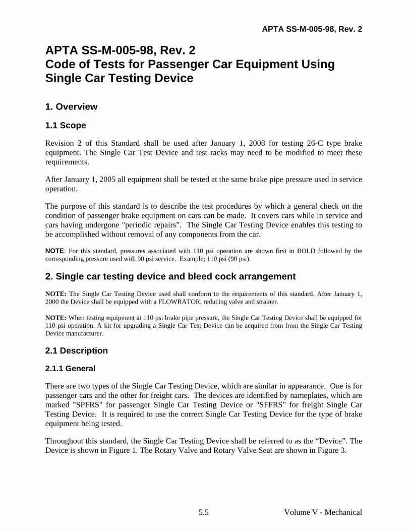
There are two types of the Single Car Testing Device, which are similar in appearance. One is for passenger cars and the other for freight cars. The devices are identified by nameplates, which are marked "SPFRS" for passenger Single Car Testing Device or "SFFRS" for freight Single Car Testing Device. It is required to use the correct Single Car Testing Device for the type of brake equipment being tested.
Throughout this standard, the Single Car Testing Device shall be referred to as the “Device”. The Device is shown in Figure 1. The Rotary Valve and Rotary Valve Seat are shown in Figure 3.
APTA SS-M-005-98, Rev. 2
Volume V - Mechanical 5.6
Figure 1 Standard Passenger Single Car Testing Device with FLOWRATOR (SPFRS designation)
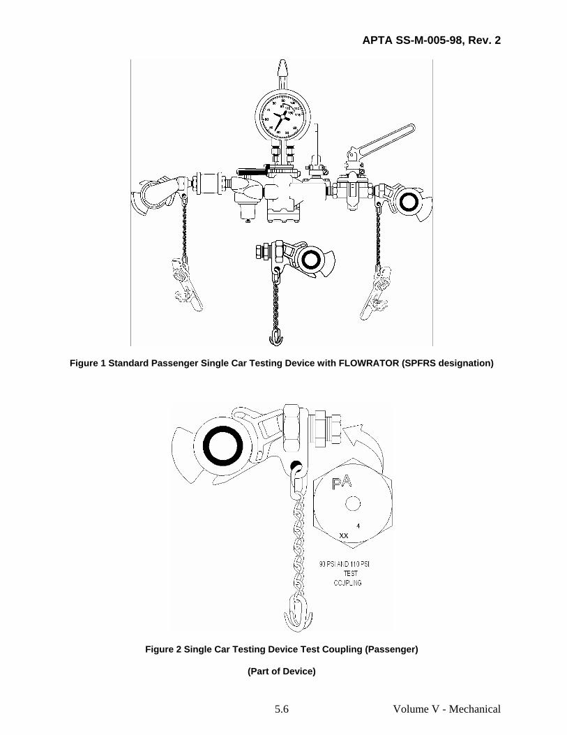
Figure 2 Single Car Testing Device Test Coupling (Passenger)
(Part of Device)
APTA SS-M-005-98, Rev. 2
Volume V - Mechanical 5.7
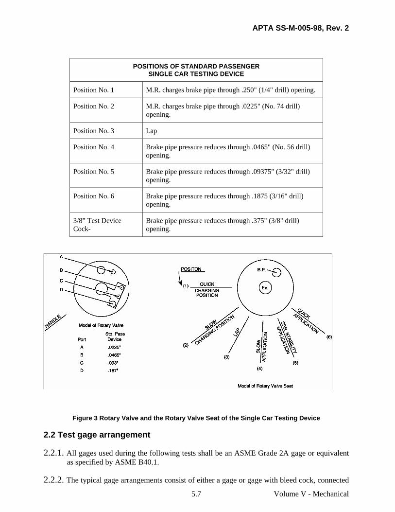
POSITIONS OF STANDARD PASSENGER SINGLE CAR TESTING DEVICE
Position No. 1 M.R. charges brake pipe through .250" (1/4" drill) opening.
Position No. 2 M.R. charges brake pipe through .0225" (No. 74 drill) opening.
Position No. 3 Lap
Position No. 4 Brake pipe pressure reduces through .0465" (No. 56 drill) opening.
Position No. 5 Brake pipe pressure reduces through .09375" (3/32" drill) opening.
Position No. 6 Brake pipe pressure reduces through .1875 (3/16" drill) opening.
3/8” Test Device Cock-
Brake pipe pressure reduces through .375" (3/8" drill) opening.
Figure 3 Rotary Valve and the Rotary Valve Seat of the Single Car Testing Device
2.2 Test gage arrangement
2.2.1. All gages used during the following tests shall be an ASME Grade 2A gage or equivalent as specified by ASME B40.1.
2.2.2. The typical gage arrangements consist of either a gage or gage with bleed cock, connected
APTA SS-M-005-98, Rev. 2
Volume V - Mechanical 5.8
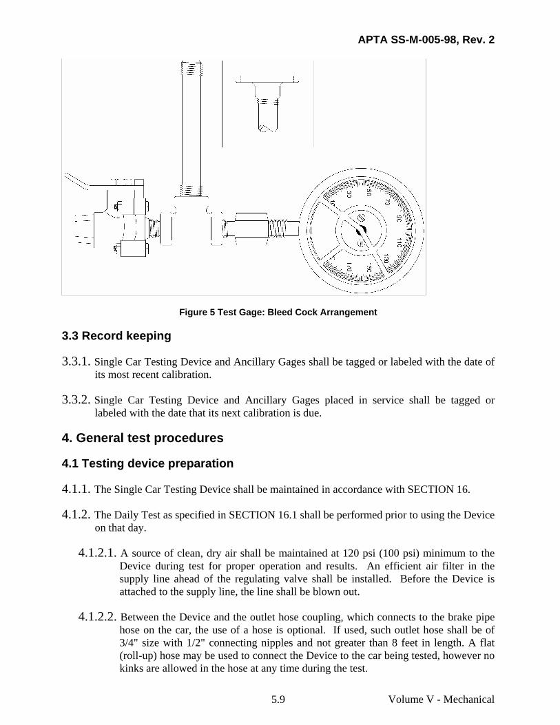
to short length of hose and the appropriate equipment interface fitting (flange, test point, pipe tap, etc). The equipment interface fittings shall provide an airtight seal and should be checked whenever leakage is detected during the test. Use the correct interface fitting for each test gage connection as determined by the equipment manufacturer/operating authority. Figure 5 shows a typical test gage with bleed cock and pipe thread/flange fitting.
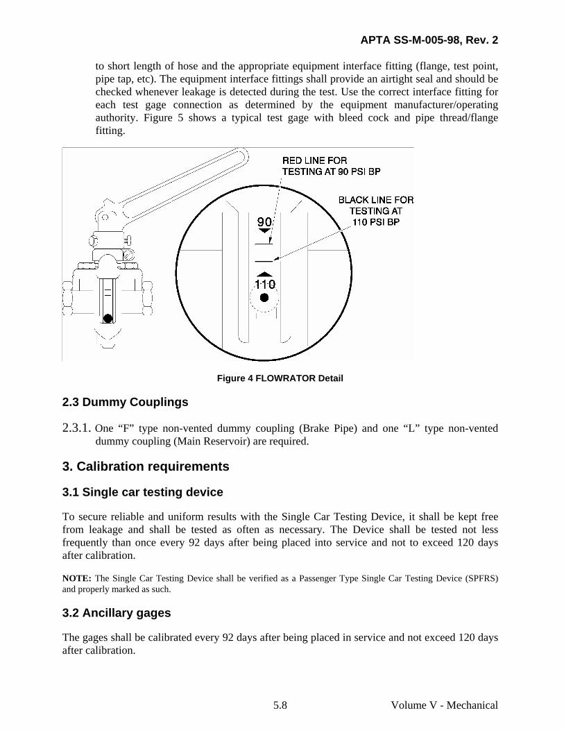
Figure 4 FLOWRATOR Detail
2.3 Dummy Couplings
2.3.1. One “F” type non-vented dummy coupling (Brake Pipe) and one “L” type non-vented dummy coupling (Main Reservoir) are required.
3. Calibration requirements
3.1 Single car testing device
To secure reliable and uniform results with the Single Car Testing Device, it shall be kept free from leakage and shall be tested as often as necessary. The Device shall be tested not less frequently than once every 92 days after being placed into service and not to exceed 120 days after calibration.
NOTE: The Single Car Testing Device shall be verified as a Passenger Type Single Car Testing Device (SPFRS) and properly marked as such.
3.2 Ancillary gages
The gages shall be calibrated every 92 days after being placed in service and not exceed 120 days after calibration.
APTA SS-M-005-98, Rev. 2
Volume V - Mechanical 5.9
Figure 5 Test Gage: Bleed Cock Arrangement
3.3 Record keeping
3.3.1. Single Car Testing Device and Ancillary Gages shall be tagged or labeled with the date of its most recent calibration.
3.3.2. Single Car Testing Device and Ancillary Gages placed in service shall be tagged or labeled with the date that its next calibration is due.
4. General test procedures
4.1 Testing device preparation
4.1.1. The Single Car Testing Device shall be maintained in accordance with SECTION 16.
4.1.2. The Daily Test as specified in SECTION 16.1 shall be performed prior to using the Device on that day.
4.1.2.1. A source of clean, dry air shall be maintained at 120 psi (100 psi) minimum to the Device during test for proper operation and results. An efficient air filter in the supply line ahead of the regulating valve shall be installed. Before the Device is attached to the supply line, the line shall be blown out.
4.1.2.2. Between the Device and the outlet hose coupling, which connects to the brake pipe hose on the car, the use of a hose is optional. If used, such outlet hose shall be of 3/4" size with 1/2" connecting nipples and not greater than 8 feet in length. A flat (roll-up) hose may be used to connect the Device to the car being tested, however no kinks are allowed in the hose at any time during the test.
APTA SS-M-005-98, Rev. 2
Volume V - Mechanical 5.10
4.1.2.3. FLOWRATOR tube shall be within 15 degrees of vertical.
4.1.2.4. The Device ends, Device exhausts and test coupling shall be protected from contamination (entry of dirt).
4.1.2.5. The tests are to be made with the Device reducing valve adjusted for 110 psi (90 psi).
4.1.3. Care should be exercised in moving the Device handle back to Position No. 3 (Lap) after making brake pipe reductions of 15 psi or more in Position No. 5 and Position No. 6. When the handle is snapped back, the temperature effect may cause the brake pipe pressure to rise 1-1/2 to 2 psi and may be the cause of an undesired release. The Device handle should be moved slowly toward Lap position.
4.1.4. When making tests of cars having two sets of brake equipment, each set shall be tested separately, with the branch pipe Cut-Out Cock closed to one set while the other set is being tested.
4.1.5. In the event of the valve failing to pass the specified test, it shall be ascertained that the Device and any test gage attachments are not at fault.
4.1.6. To determine a “fully charged system” utilizing the FLOWRATOR, move the Device handle in Position No. 1 and close the FLOWRATOR by-pass cock. If ball remains below the condemning line (refer to 4.1.6.2) of the FLOWRATOR tube the system is fully charged, open the FLOWRATOR by-pass cock. If the ball rises above the condemning line of the FLOWRATOR tube the system is not fully charged or the system has excess leakage, open the FLOWRATOR by-pass cock and allow the system to continue charging or assess potential leakage sources.
4.1.6.1. For equipment, which utilizes equalization of the brake cylinder supply reservoir to the brake cylinders, a longer time period may be required to properly charge the control reservoir even if the FLOWRATOR ball is below the condemning line.
4.1.6.2. When using a FLOWRATOR calibrated for both 110 psi and 90 psi brake pipe use the upper condemning (Red) line for 90 psi brake pipe and the lower (Black) line for 110 psi brake pipe as shown in Figure 4.
4.1.7. If using a Device when the FLOWRATOR has been disqualified by the daily test in SECTION 16.1, the determination of a “fully charged system” may be performed as follows:
4.1.7.1. Move the Device handle to Position No. 3 (Lap) for 5 seconds. If the brake pipe pressure decreases, the system is not fully charged or the system has excess leakage. Move the Device handle to Position No. 1 and continue charging or assess potential leakage sources.
APTA SS-M-005-98, Rev. 2
Volume V - Mechanical 5.11
4.2 General information
4.2.1. As used in this standard, pounds per square inch (psi) shall indicate pressure as pounds per square inch gage (psig) unless otherwise specified. The pressure measured is greater than ambient using ambient pressure as the reference.
4.2.2. As used in this standard, brake cylinder refers to all components connected to the brake cylinder line including but not limited to the brake cylinder piping, tread brake units, disc brake units, brake cylinder indicators and wheel slide protection equipment.
4.2.3. As used in this standard, the term “Cut In” (OPEN) will be used to designate a cut-out cock that will allow the passage of air between equipment components. The Term “Cut Out” (CLOSED) will be used to designate a cut-out cock that will prevent the flow of air between equipment components.
4.2.4. Any ancillary equipment not tested by this standard shall be tested in accordance with equipment manufacturer/operating authority instructions.
4.2.5. Passenger cars equipped with freight brake systems shall be tested in accordance with equipment manufacturer/operating authority instructions based upon current Federal Regulations.
4.2.6. When a car is equipped with a main reservoir pipe, air pressure of 120 psi (100 psi) minimum should be connected to the main reservoir trainline as instructed in the standard. The dual air source arrangement (brake pipe and main reservoir) will aid in reducing the test time and will not compromise test results.
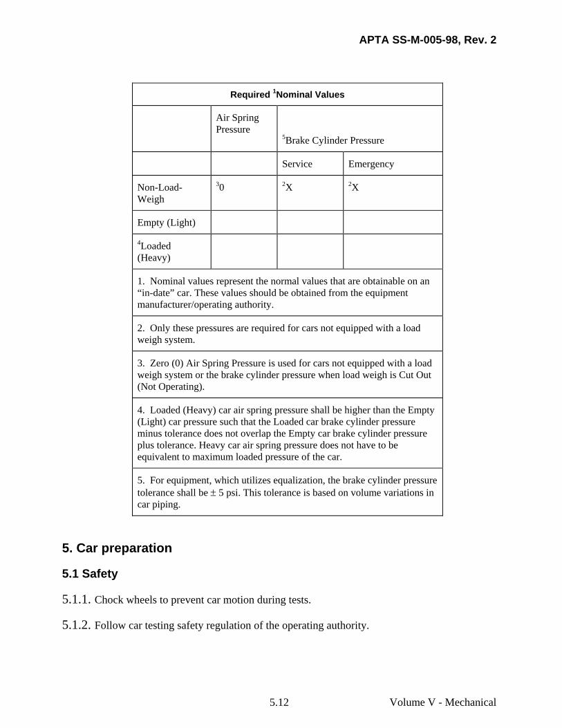
4.2.7. The following Nominal values need to be obtained from the operating authority for use in testing:
APTA SS-M-005-98, Rev. 2
Volume V - Mechanical 5.12
Required 1Nominal Values
Air Spring Pressure
5Brake Cylinder Pressure
Service Emergency
Non-Load-Weigh
30 2X 2X
Empty (Light)
4Loaded (Heavy)
1. Nominal values represent the normal values that are obtainable on an “in-date” car. These values should be obtained from the equipment manufacturer/operating authority.
2. Only these pressures are required for cars not equipped with a load weigh system.
3. Zero (0) Air Spring Pressure is used for cars not equipped with a load weigh system or the brake cylinder pressure when load weigh is Cut Out (Not Operating).
4. Loaded (Heavy) car air spring pressure shall be higher than the Empty (Light) car pressure such that the Loaded car brake cylinder pressure minus tolerance does not overlap the Empty car brake cylinder pressure plus tolerance. Heavy car air spring pressure does not have to be equivalent to maximum loaded pressure of the car.
5. For equipment, which utilizes equalization, the brake cylinder pressure tolerance shall be ± 5 psi. This tolerance is based on volume variations in car piping.
5. Car preparation
5.1 Safety
5.1.1. Chock wheels to prevent car motion during tests.
5.1.2. Follow car testing safety regulation of the operating authority.
APTA SS-M-005-98, Rev. 2
5.2 Car setup
5.2.1. Open cut-out cock between the Main Reservoir and Air Spring system if equipped.
5.2.2. Ensure that the hand brake/parking brakes are released where applicable.
5.2.3. If testing a cab car, the cab equipment details shall be conditioned so that the car brake equipment functions as a trailer car. Refer to equipment manufacturer/operating authority procedures for conditioning cab car equipment.
5.2.4. Water raising equipment should be Cut Out at the water filling valves or other appropriate locations as instructed by equipment manufacturer/operating authority.
5.2.5. Other ancillary equipment shall be Cut Out.
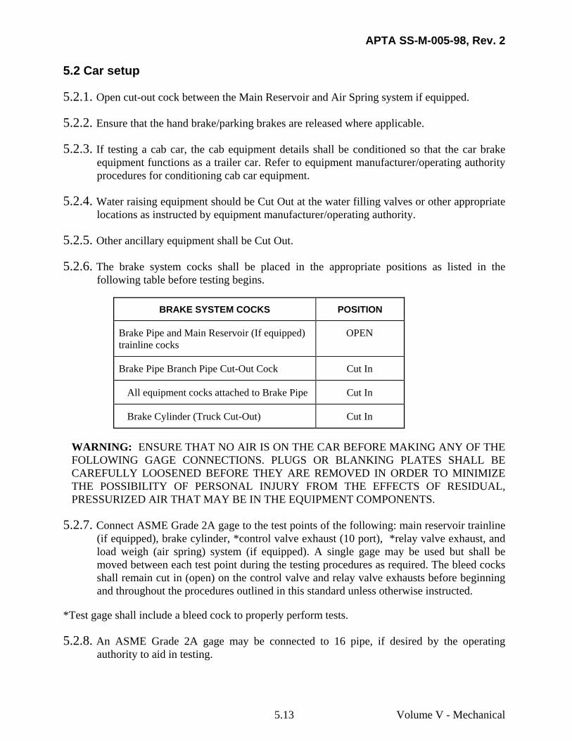
5.2.6. The brake system cocks shall be placed in the appropriate positions as listed in the following table before testing begins.
BRAKE SYSTEM COCKS POSITION
Brake Pipe and Main Reservoir (If equipped) trainline cocks
OPEN
Brake Pipe Branch Pipe Cut-Out Cock Cut In
All equipment cocks attached to Brake Pipe Cut In
Brake Cylinder (Truck Cut-Out) Cut In
WARNING: ENSURE THAT NO AIR IS ON THE CAR BEFORE MAKING ANY OF THE FOLLOWING GAGE CONNECTIONS. PLUGS OR BLANKING PLATES SHALL BE CAREFULLY LOOSENED BEFORE THEY ARE REMOVED IN ORDER TO MINIMIZE THE POSSIBILITY OF PERSONAL INJURY FROM THE EFFECTS OF RESIDUAL, PRESSURIZED AIR THAT MAY BE IN THE EQUIPMENT COMPONENTS.
5.2.7. Connect ASME Grade 2A gage to the test points of the following: main reservoir trainline (if equipped), brake cylinder, *control valve exhaust (10 port), *relay valve exhaust, and load weigh (air spring) system (if equipped). A single gage may be used but shall be moved between each test point during the testing procedures as required. The bleed cocks shall remain cut in (open) on the control valve and relay valve exhausts before beginning and throughout the procedures outlined in this standard unless otherwise instructed.
*Test gage shall include a bleed cock to properly perform tests.
5.2.8. An ASME Grade 2A gage may be connected to 16 pipe, if desired by the operating authority to aid in testing.
Volume V - Mechanical 5.13
APTA SS-M-005-98, Rev. 2
6. Test equipment installation
6.1 Connecting the device to car
WARNING: CARE SHOULD BE TAKEN THAT ALL SUPPLY AIR IS CUT OUT TO PREVENT ANY WHIPPING OR LASHING OF HOSES AND COUPLINGS. MAKE CERTAIN THAT ALL TEST GAGES AND THE DEVICE ARE FASTENED AND/OR CONNECTED SECURELY TO MINIMIZE THE POSSIBILITY OF PERSONAL INJURY FROM PARTS THAT MAY BE “BLOWN” FROM THE TEST ARRANGEMENT WHEN AIR IS ADMITTED TO THE DEVICE OR BRAKE EQUIPMENT.
6.1.1. Connect the Device end marked B.P. to the brake pipe hose at one end of the car (preferably at "B", hand brake, end of car). Make sure that the FLOWRATOR by-pass cock is open. Open supply air cut-out cock. Move the Device handle to Position No. 1. With both angle cocks open, note a continuous blow of air from the open hose occurs at the other end of the car. Close the Brake Pipe angle/end cock at the end opposite the Device, and couple on a non-vented “F” type dummy hose coupling. Open the Brake Pipe angle/end cock at the end opposite the Device. Continue charging the brake pipe and reservoirs to 110 psi (90 psi).
7. Leakage tests
7.1 System leakage test
7.1.1. Close the FLOWRATOR by-pass cock. If the ball is not above the condemning line, open the FLOWRATOR by-pass cock and proceed directly to SECTION 7.2 Main Reservoir Leakage (if equipped). If any part of the ball is above the condemning line, make a complete check for leakage (with soap suds when weather conditions permit) of all pipes and pipe connections, including angle cocks, hoses, check valves and auxiliary components.
7.1.2. If leakage is found, make repairs necessary to reduce it to where the ball of the FLOWRATOR stays below the condemning line, then open the FLOWRATOR by-pass cock and proceed to SECTION 7.2 Main Reservoir Leakage (if equipped).
7.1.2.1. Excessive brake system leakage may be caused by absorption of air by water raising system or other auxiliary components.
7.1.2.2. If air is detected exhausting from the main reservoir trainline at the Device end of car, the main reservoir check valve(s) shall be corrected/replaced. It may be necessary to temporarily close the opposite end main reservoir trainline end cock during this trouble shooting procedure.
Volume V - Mechanical 5.14
APTA SS-M-005-98, Rev. 2
7.2 Main reservoir leakage
NOTE: For cars not equipped with a main reservoir trainline, proceed to SECTION 8.
NOTE: Cars equipped with a main reservoir pipe (pass-through) that is not connected to the supply reservoir shall be tested in accordance with SECTION 14.3, proceed to SECTION 8.
7.2.1. Before making any hose connection the supply line shall be blown out.
With the test air supply cut-out cock closed, make a connection of a 120 psi (100 psi) minimum supply air (air shall be from a clean, dry source) to the main reservoir pipe hose at one end of the car. Note: The air supplied to the main reservoir pipe shall be taken from the supply side of the Device or an alternate air supply line.
7.2.2. Partially open the test air supply cut-out cock. Note the continuous blow of air from the main reservoir hose opening at the opposite end of the car.
7.2.3. Close the main reservoir trainline cock. Connect a non-vented “L” type dummy hose coupling to the main reservoir pipe hose coupling at the end of the car opposite the test supply air connection. Open the main reservoir trainline cock.
7.2.4. Confirm installation of an air gage to the main reservoir trainline.
7.2.5. Open the main reservoir test air supply cock and fully charge the main reservoir system.
7.2.6. Move the Device handle to Position No. 5, and make a 10 psi reduction in brake pipe. Move the Device handle in Position No. 3 (Lap).
7.2.7. After 30 seconds, observe the Device gage, pressure increase shall not exceed 3 psi in 1 minute and shall stabilize.
7.2.8. Close the main reservoir test air supply cock.
7.2.9. Observe the main reservoir gage, pressure decrease shall not exceed 5 psi in 1 minute.
7.2.10. Open the main reservoir test air supply cock. Move the Device handle to Position No. 1 and fully charge the brake equipment.
8. Functionality testing
8.1 Preparation
8.1.1. Cars equipped with load weigh systems shall either temporarily disable the variable load valve or inhibit its operation. The air spring pressure shall be reduced a minimum of 10 psi below the Light (Empty Car) air spring pressure.
NOTE: Some variable load valve arrangements may require that the air spring pressure be reduced to zero (0) psi for proper determination of the non-load-weigh brake cylinder pressure. Check with equipment manufacturer/operating authority for details on preparation of equipment for this test.
Volume V - Mechanical 5.15
APTA SS-M-005-98, Rev. 2
8.2 Service stability test
8.2.1. Confirm installation of an air gage in the brake cylinder line. With the equipment fully charged, move the Device handle to Position No. 5, reducing brake pipe pressure 25 psi, then slowly move handle to Position No. 3 (Lap). This test shall not produce an emergency application. Observe brake cylinder gage, and verify that the non-load weigh service brake cylinder pressure + 3 psi as specified is correct.
8.2.2. Allow 20 seconds settling time for brake cylinder pressure then note that brake cylinder pressure increases no more than 3 psi in 1 minute. A brake cylinder pressure increase greater than 3 psi during this 1-minute period indicates a faulty relay valve portion, control valve service portion, or variable load valve, if equipped. Replace defective component.
8.3 Release testing
NOTE: Cars shall be tested for Direct or Graduated release based on the type of service in which the car is used. If a car is used in both Graduated and Direct service, the system shall be tested in both graduated and direct release operation with the Graduated/Direct Release Cap set to the mode of operation being tested. Testing of the equipment graduated release function (if applicable) will be performed in SECTION 13.
CAUTION - When changing the Graduated/Direct Release Cap or other related covers, refer to the equipment manufacturer/operating authority instructions.
8.3.1 Release test
NOTE: For cars operated in Direct release service ensure that the Graduated/Direct release cap is in the Direct release position. Cars operated only in Graduated release service shall have the Graduated/Direct release cap left in the Graduated release position.
8.3.1.1. With a 25 psi brake pipe reduction in effect, move the Device handle to Position No. 1 until brake pipe pressure has increased 10 to 11 psi, then move handle to Position No. 3 (Lap).
a) Cap in Direct Release - Brake cylinder control (port 10 exhaust) pressure shall fully exhaust.
b) Cap in Graduated Release – Brake cylinder control (port 10 exhaust) pressure shall partially exhaust.
8.3.1.2. Move the Device handle to Position No. 1 to fully recharge the brake pipe and reservoirs. Check that the equipment is fully charged.
8.4 Application test
NOTE: For PS-68 Type brake equipment, a 10 psi reduction is required.
8.4.1. With the equipment fully charged, move the Device handle to Position No. 5 until a 5 psi brake pipe reduction is obtained, then slowly move the handle to Position No. 3 (Lap). The brake pipe pressure shall continue to drop to within an 104 psi (84 psi) maximum and 100psi (80 psi) minimum allowable pressure range. If brake pipe pressure stabilizes
Volume V - Mechanical 5.16
APTA SS-M-005-98, Rev. 2
between 100 psi (80 psi)and 104 psi (84 psi) then proceed to SECTION 8.4.2.
8.4.1.1. If brake pipe pressure continues to decrease and the car is equipped with an accelerated/continuous service application feature (B-1 Quick Service Valve or Accelerated Application Valve), a greater quick service activity may be indicated by the continual decrease in brake pipe pressure. Move the Device handle to Position No. 2 until the brake pipe pressure stops reducing, then immediately move the Device handle back to Position No. 3 (Lap). If the pressure does not stop reducing before 94 psi (74 psi), while the Device handle is in Position No. 2, the control valve service portion or the portion with the accelerated/continuous service application feature is defective and shall be replaced.
8.4.2. Allow 20 seconds for the brake cylinder gage to stabilize. The brake cylinder pressure shall not increase/decrease more than 3 psi in 1 minute. If the pressure requirement is not met, the relay valve portion, the control valve service portion, or the variable load valve portion, if so equipped, is defective and the appropriate valve portion shall be removed and replaced. With this application, the brake shoes/pads shall be in firm contact with the braking surfaces.
8.5 Release sensitivity test
NOTE: During the Release Sensitivity Test, the reducing valve supply pressure shall not decrease more than 2 psi.
8.5.1. Move the Device handle to Position No. 2.
8.5.2. Brake cylinder pressure shall begin to decrease within 90 seconds as indicated by an exhaust of air from the control valve exhaust (port 10). Failure to release in the time specified indicates a faulty control valve service portion. Defective component shall be replaced.
8.5.3. Continue the test until brake cylinder pressure is zero (0) psi and brake shoes/pads are fully released from the braking surfaces as defined by the equipment manufacturer/operating authority.
8.5.4. Failure to obtain the proper brake release may be due to defective control valve service portion, defective relay valve or excessive brake rigging resistance. The following procedure will indicate which part of the equipment is responsible for this condition. If the test performed in SECTIONS 8.5.2 and 8.5.3 are passed then proceed to SECTION 8.5.5.
8.5.4.1 Control valve
During the Release Sensitivity Test, an exhaust of air should occur at the exhaust port (port 10). A continuous blow at this exhaust port, however, indicates that the control valve service portion is defective and shall be replaced.
8.5.4.2 Brake cylinders
Close the brake cylinder cut-out cocks, and vent brake cylinder air to atmosphere. If the brake shoes/pads return to release position, the rigging is not at fault. Return the brake
Volume V - Mechanical 5.17
APTA SS-M-005-98, Rev. 2
cylinder cut-out cocks to their normal operating position. If the rigging is at fault then the source of rigging resistance shall be corrected.
8.5.4.3 Relay valve
If the trouble has not been located in the control valve or brake rigging, it indicates that the difficulty is with the relay valve portion. A plugged or obstructed atmospheric vent port leading to the outer face of the inshot diaphragm, or leading to the space between the differential diaphragms, may be the cause of the failure of the brake to release. If the vent ports are open, the portion is defective and shall be replaced.
8.5.5. Move the Device handle to Position No. 1 and fully recharge the brake system.
9. Emergency brake application tests
9.1 Emergency test (auxiliary venting portions)
NOTE: The following test shall be individually performed for each auxiliary venting portion on the car. Portions not being tested shall be Cut Out/Plugged.
9.1.1. Plug all auxiliary brake pipe emergency venting portions except the one being tested.
9.1.2. Verify that the system is fully charged. Move the Device handle to Position No. 5 and make a 30 psi reduction in brake pipe pressure. Move the Device handle to Position No. 3 (Lap).
9.1.3. Cut Out/Plug the control valve/operating unit emergency venting portion.
9.1.4. With the Device handle in Position No. 3 (Lap), open the Device 3/8" cock. This test shall produce an emergency reduction as indicated by the opening of the auxiliary venting portion and the sudden decrease in brake pipe pressure.
9.1.4.1. Failure to obtain an emergency reduction may be caused by a decrease in the auxiliary venting portion volume (accumulation of excessive moisture) or a restricted orifice. The defective component shall be replaced.
9.1.5. Close the Device 3/8” cock.
9.1.6. If this is the last venting portion to be tested then install a plug in the tested portion, proceed to SECTION 9.1.7. Otherwise move the Device handle to Position No. 1 and recharge equipment. Proceed to SECTION 9.1.1 to test the remaining auxiliary venting portions.
9.1.7. Move the Device handle to Position No. 1 to fully recharge brake pipe and reservoirs. While system is charging, Cut In/unplug the control valve/operating unit emergency venting portion.
9.2 Emergency test (control valve/operating unit) Volume V - Mechanical 5.18
APTA SS-M-005-98, Rev. 2
9.2.1. Verify all auxiliary venting portion(s) are plugged.
9.2.2. With the equipment fully charged, move the Device handle to Position No. 5 and make a 30 psi reduction in brake pipe pressure. Move the Device handle to Position No. 3 (Lap).
9.2.3. Open the Device 3/8” cock. This test shall produce an emergency application as indicated by opening of the control valve/operating unit emergency venting portion and the sudden decrease in brake pipe pressure.
9.2.3.1. Observe brake cylinder gage, and verify that the non-load weigh emergency brake cylinder pressure + 3 psi (or equalization pressure) as specified is correct.
9.2.4. Failure to obtain an emergency application may be caused by a decrease in the quick action chamber volume in the pipe bracket (accumulation of excessive moisture), a restricted quick action chamber charging choke or defective emergency venting portion. The defective component shall be replaced.
9.2.5. Remove plugs from all emergency venting portions and install all vent protectors.
9.3 Brake cylinder cut-out cocks
NOTE: If car is equipped with remote handles on the brake cylinder cut-out cocks, assure proper operation of the remote handles during this test.
9.3.1. Close one brake cylinder cut-out cock and verify that the associated brakes release as indicated by the release of the brake shoes/pads from the braking surfaces as defined by the equipment manufacturer/operating authority.
9.3.1.1. During the above test also verify the proper operation of any brake cylinder pressure indicators (including illuminated indicators). The defective components shall be replaced.
9.3.2. Normalize brake cylinder cut-out cock.
9.3.3. Repeat item 9.3.1 for each brake cylinder cut-out cock on the car.
9.4 Release test after emergency
9.4.1. At the completion of the Emergency Tests, close the Device 3/8" cock. After 2 minutes, if brake pipe pressure rises on the Device gage, the control valve service portion is defective and shall be replaced.
9.4.2. Move the Device handle to Position No. 1 and recharge the equipment.
Volume V - Mechanical 5.19
APTA SS-M-005-98, Rev. 2
Volume V – Mechanical 5.20
10. Leakage tests – control and brake cylinder
10.1 Control valve
10.1.1. Verify connection of the gage to the control valve exhaust (10 port) and close the bleed cock.
10.1.2. With the equipment fully charged reduce brake pipe pressure 26 psi in Position No. 5 then move the Device handle to Position No. 1. If test gage indicates a pressure in excess of 50 psi, the pressure shall be reduced to 50 psi through the bleed cock.
10.1.3. Observe the test gage for leakage from the combined volumes of the relay valve diaphragm chamber, 16 pipe/10 port (if used) and their related piping, which shall not exceed 2 psi in 1 minute.
10.1.4. If the drop in pressure exceeds 2 psi in 1 minute, inspect the 16 pipe/10 port and 16 pipe/10 port pipe as well as all other related piping, and eliminate any leakage. Initially check the gage installed for the leakage test in the 16 pipe/10 port for leakage before checking the remainder of the system. If no leakage is found, or if the elimination of the leakage found does not reduce the drop in pressure observed on the test gage to less than the limit specified, it indicates either a faulty relay valve, control valve, or a combination of related components, in which case the defective conditions shall be corrected. If the drop in pressure does not exceed the above specified limit, proceed to Brake Cylinder Leakage SECTION 10.2.
10.2 Brake cylinder leakage
NOTE: If the car is not equipped with a brake cylinder relay valve, proceed to Emergency Brake (Conductor’s Valve Test) SECTION 11.
10.2.1. With the equipment fully charged, open the bleed cock on 10 port.
10.2.2. Verify connection of the gage to the relay valve exhaust and close the bleed cock.
10.2.3. Reduce brake pipe pressure 26 psi in Position No. 5 then move the Device handle to Position No. 1. Leave the handle of the Device in Position No. 1. The pressure obtained by the reduction shall be the non-load-weigh full service brake cylinder pressure but not to exceed 50 psi. If the pressure on the test gage is in excess of 50 psi, the pressure shall be reduced to 50 psi through the bleed cock.
10.2.4. Observe the relay valve exhaust test gage for leakage from the combined volumes of the brake cylinders and their related piping. The drop in pressure shall not exceed 3 psi in 1 minute.
10.2.4.1. If the drop in pressure exceeds the amount specified, inspect the brake cylinder and brake cylinder pipe, and eliminate any leakage. Initially check the gage installed for the leakage test for leakage before checking the remainder of the system. If no leakage is found, or if the elimination of the leakage found does not reduce the leakage observed on the test gage to less than the limits specified, it indicates a faulty brake cylinder or cylinders, in which case the
APTA SS-M-005-98, Rev. 2
Volume V - Mechanical 5.21
defective conditions shall be corrected. If the drop in pressure does not exceed the above specified limits, open gage fitting bleed cock or cocks and remove exhaust gage fitting or fittings.
11. Emergency brake (conductor's) valve test
11.1 Valve test
NOTE: The following test shall be performed for the first Emergency Brake Valve tested on the car. The remaining Emergency Brake Valves shall be tested in accordance with the Remaining Valves SECTION 11.2. For Emergency Brake Valves equipped with multiple operating mechanisms, each operating mechanism must be verified.
11.1.1. With the equipment fully charged, and the Device handle in Position No. 1, open the emergency brake (conductor's) valve, observing carefully that there are no obstructions to the free and full movement of the operating mechanism, and that there is no binding of parts. The opening of the emergency brake (conductor's) valve shall produce an emergency reduction. If an emergency reduction is not obtained, a restriction to air flow in the valve pipe is disclosed, which shall be located and removed. It may also be due to failure of the application valve in the emergency brake (conductor's) valve line to open, if the car is equipped with the application valve. The defective component shall be replaced.
11.2 Remaining valves
Repeat the above operation for each remaining emergency brake (conductor's) valve. Allow sufficient time after testing of each valve so that the system may reset and begin to charge. A full charge of the brake system is not required to test the function of the remaining Emergency Brake (Conductor’s) Valves and application valves.
12. Variable load control
For cars not equipped with a variable load control system, proceed to SECTION 13.
NOTE: The following section provides a guide to testing the variable load control system. The test may be performed as described below or the test may be modified or performed in any sequence to meet the specific operation of a particular variable load control system. The modified procedure shall agree with the original equipment manufacturer’s requirements.
12.1 Empty (light) car
12.1.1. Increase the Air Spring pressure to within ± 1 psi of the Empty (Light) Car pressure, as specified in SECTION 4.2.7.
12.1.2. With the equipment fully charged, move the Device handle to Position No. 5 until a 30 psi brake pipe reduction is obtained, then slowly move the Device handle to Position No. 3 (Lap). When testing cars equipped with an accelerated, continuous service application feature (B-1 Quick Service Valve or Accelerated Application Valve), a greater quick service activity will be indicated by the continual decrease in brake pipe pressure. If brake pipe pressure has not stopped dropping before it reaches 55 psi, as indicated by the Device gage, move the Device handle to Position No. 2 until the brake
APTA SS-M-005-98, Rev. 2
Volume V - Mechanical 5.22
pipe pressure stops reducing, then immediately move the Device handle back to Position No. 3 (Lap).
12.1.3. Allow 20 seconds for the system to stabilize. Observe that the brake cylinder gage pressure is within + 3 psi of the Empty (Light) Car full service brake cylinder pressure as specified is correct.
12.1.3.1. If the brake cylinder pressure is higher/lower than the Empty (Light) Car pressure, the variable load valve portion shall be corrected or replaced.
12.1.4. Move the Device handle to Position No. 1 and fully recharge the system. Move the Device handle to Position No. 3 (Lap).
12.1.5. Open the Device 3/8” cock. The test shall produce an emergency brake application.
12.1.6. Allow 20 seconds for the system to stabilize. Observe that the brake cylinder gage pressure is within + 3 psi of the Empty (Light) Car emergency brake cylinder pressure as specified is correct.
12.1.7. Close the Device 3/8” cock. Move the Device handle to Position No. 1.
12.2 Loaded (heavy) car
12.2.1. Increase the Air Spring pressure to within ± 1 psi of the Loaded (Heavy) Car pressure, as specified in SECTION 4.2.7.
12.2.2. With the equipment fully charged, move the Device handle to Position No. 5 until a 30 psi brake pipe reduction is obtained, then slowly move the Device handle to Position No. 3 (Lap). When testing cars equipped with an accelerated, continuous service application feature (B-1 Quick Service Valve or Accelerated Application Valve), a greater quick service activity will be indicated by the continual decrease in brake pipe pressure. If brake pipe pressure has not stopped dropping before it reaches 55 psi, as indicated by the Device gage, move the Device handle to Position No. 2 until the brake pipe pressure stops reducing, then immediately move the Device handle back to Position No. 3 (Lap).
12.2.3. Allow 20 seconds for the system to stabilize. Observe that the brake cylinder gage pressure is within + 3 psi of the Loaded (Heavy) car full service brake cylinder pressure as specified is correct.
12.2.3.1. If the brake cylinder pressure is higher/lower than the Loaded (Heavy) Car full service brake cylinder pressure, the variable load valve portion shall be corrected or replaced.
12.2.4. Move the Device handle to Position No. 1 and fully recharge the system. Move the Device handle to Position No. 3 (Lap).
12.2.5. Open the Device 3/8” cock. The test shall produce an emergency brake application.
APTA SS-M-005-98, Rev. 2
Volume V - Mechanical 5.23
12.2.6. Allow 20 seconds for the system to stabilize. Observe that the brake cylinder gage pressure is within + 3 psi of the Loaded (Heavy) car emergency brake cylinder pressure as specified is correct.
12.2.7. Close the Device 3/8” cock.
13. Graduated release test
For cars operated only in direct release service, proceed to SECTION 14.
NOTE: Cars operated only in Graduated release service or cars operated in both Graduated and Direct release service shall be tested by this section. Ensure that the Graduated/Direct release cap is placed in the Graduated position before proceeding with this section.
Cars equipped with variable load control systems shall be tested in the Loaded (Heavy) Car condition.
CAUTION - When changing the Graduated/Direct Release Cap or other related covers, refer to the equipment manufacturer/operating authority instructions.
13.1.1. Move the Device handle to Position No. 1 to fully recharge the brake pipe and reservoirs.
13.1.2. Make a 25 psi brake pipe reduction then move the Device handle to Position No. 3 (Lap).
13.1.3. Move the Device handle to Position No. 1 until brake pipe pressure has increased 5 to 6 psi, then move the Device handle to Position No. 3 (Lap). Brake cylinder control (port 10 exhaust) pressure shall partially exhaust and stabilize. Repeat SECTION 13.1.3 until at least three separate brake cylinder control pressure exhausts (graduations) have been obtained.
14. Miscellaneous devices
If the car is equipped with any of the equipment listed below, it shall also be tested as part of the Single Car Test. At completion of previous testing, brake equipment will have brakes applied. Manufacturer/operating authority instructions shall be followed to condition equipment for the following tests.
14.1 Hand brake/parking brake
14.1.1. Hand brake/parking brake unit shall be tested in accordance with manufacturer/operating authority instructions.
14.2 Wheel slide protection equipment
14.2.1. Wheel Slide equipment shall be tested in accordance with manufacturer/operating authority instructions.
14.3 Main reservoir pipe (pass-through)
NOTE: “Pass-Through” means no pneumatic equipment connected to the pipe.
APTA SS-M-005-98, Rev. 2
Volume V - Mechanical 5.24
14.3.1. Connect an ASME Grade 2A gage to the Main Reservoir Pipe.
14.3.2. Before making any hose connection the supply line shall be blown out.
14.3.3. Make a connection of 100 psi minimum supply air (air shall be from a clean dry source) to main reservoir pipe hose at one end of the car.
14.3.4. With the test air supply cut-out cock closed, open the main reservoir trainline cock at the end of the car opposite the supply air connection.
14.3.5. Partially open the test air supply line cut-out cock. Note the continuous blow of air from the main reservoir hose opening at the opposite end of the car.
14.3.6. Close the main reservoir trainline cock.
14.3.7. Connect a non-vented “L” type dummy hose coupling to main reservoir pipe hose coupling at the end of the car opposite the test supply air connection.
14.3.8. Open the main reservoir trainline cock.
14.3.9. Pressurize the Main Reservoir Pipe to 100 psi minimum and close air supply cut-out cock. Allow the pressure to stabilize for 30 seconds.
14.3.10. Observe test gage, pressure decrease shall not exceed 5 psi in one minute.
14.3.11. Following completion of test, vent air and remove test gauge and dummy coupling.
14.4 Conductor’s signal system
14.4.1. Conductors signal systems shall be tested in accordance with manufacturer’s instructions. If car is equipped with air signal equipment, it shall be tested in accordance with Instruction Leaflet No. 2377-2, July 1942.
14.5 Electropneumatic operation
14.5.1. Cars with Electropneumatic operation capabilities shall be tested in accordance with manufacturer/operating authority instructions.
14.6 Ancillary pneumatic equipment
14.6.1. Any ancillary pneumatic equipment not described by this standard shall be tested in accordance with manufacturer/operating authority instructions. Brake system shall not be adversely affected by ancillary pneumatic equipment operation.
15. Completion of testing
15.1 Test equipment
15.1.1. Safely remove all gages from their respective test points where applicable.
APTA SS-M-005-98, Rev. 2
Volume V - Mechanical 5.25
15.1.2. If the gages were connected by the removal of pipe plugs, leakage shall be tested. No pipe plug leakage is allowed.
15.1.3. Safely disconnect the Device from car. Connect a dummy coupling to all hose connections and the Device to prevent contamination from dust or dirt.
15.2 Final car preparation
15.2.1. Ensure hand brake/parking brake is applied.
15.2.2. Ensure all car equipment is restored to operating configuration, as specified by operating authority.
15.2.3. Record car and test information as specified by the operating authority and federal regulation.
16. Single car test device - testing
16.1 Daily test for single car testing device
16.1.1 Daily test for all single car testing devices
16.1.1.1. Connect the Device to a source of clean, dry air as specified in SECTION 4.1.2.1. A source of clean, dry air shall be maintained at 120 psi (100 psi) minimum to the Device during test for proper operation and results. An efficient air filter in the supply line ahead of the regulating (feed) valve shall be installed. Before the Device is connected to the supply line, the supply line shall be blown out. Open the FLOWRATOR by-pass cock.
16.1.1.2. Move the Device handle to Position No. 2 and note a continuous flow of air at the Device brake pipe hose coupling.
16.1.1.3. Move the Device handle to Position No. 3 (Lap). Test for leakage at brake pipe connection and rotary valve exhaust. This leakage when detected with soap suds, shall not exceed a 1" bubble in 5 seconds.
16.1.1.4. Move the Device handle to Position No. 2. Close and open FLOWRATOR by-pass cock. Observe that ball does not stay at top of tube.
16.1.1.5. Move the Device handle to Position No. 3 (Lap). Couple the test coupling with orifice to the brake pipe coupling end (BP) of the Device. Move the Device handle to Position No 1. Close the FLOWRATOR by-pass cock. Note that the FLOWRATOR ball rises and floats in the tube in the zone between the Red condemning line and the top of tube (Test applies for both 90 psi and 110 psi operation). The test coupling may be connected to the end of a hose connected to the Device as described in SECTION 4.1.2.2. However a greater time shall be given before condemning the FLOWRATOR due to the increased volume of the hose.
a) If the Device fails, check coupling and gaskets for leakage (none allowed). Inspect the
APTA SS-M-005-98, Rev. 2
Volume V - Mechanical 5.26
exhaust end of test coupling to ensure that it is clean and free of obstructions. If this does not correct the failure, the FLOWRATOR shall not be used to qualify leakage or fully charged system until the Device and test coupling are returned for maintenance to re-qualify the test coupling and FLOWRATOR.
b) If the Device FLOWRATOR has failed the above test, it may be used by following the procedures for determination of leakage/fully charged system outlined in SECTION 4.1.7.
16.1.1.6. Move the Device handle to Position No. 3 (Lap), open the FLOWRATOR by-pass cock and the Device 3/8” cock.
16.1.1.7. Remove and properly store the test coupling, close the Device 3/8” cock.
16.2 92 Day test for the single car testing device and test coupling
The Device shall be tested at either 110 psi or 90 psi based on the operating pressure of the brake equipment being tested and pass the procedure as using either the standard test rack or the alternate test rack according to the following table. If the Device is used for 110 psi and 90 psi type equipment then the 110 psi sections shall be used.
Section
Test Rack 110 psi 90 psi Test Coupling
Standard Test Rack 16.2.1 16.2.3 16.2.5
Alternate Standard Test Rack
16.2.2w 16.2.4 16.2.6
The Single Car Testing Device shall be maintained according to the requirements of SECTION 3.
The test coupling is part of the Device and shall be returned for re-qualification with the Device. Testing of the test coupling is to be performed according to SECTION 16.2.5 when using the standard test rack and SECTION 16.2.6 when using the alternate standard test rack.
As often as service conditions require, the rotary valve shall be lubricated with a suitable grease or lubricating oil (AAR Spec M-912). Lubricate the standard quick opening diaphragm cock cam with a small amount of grease (AAR Spec M-914).
The test gage shall be compared with a master gage for accuracy as often as the Device itself is being tested. The master gage is to be calibrated according to ASME standards. The calibration of the master gage shall be performed annually or as required by ASME standards.
The strainer filter shall be replaced annually unless service conditions warrant a more frequent replacement.
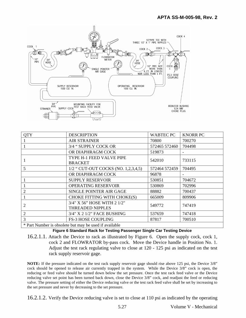
16.2.1 Test procedure for single car testing device with FLOWRATOR on standard test rack [for 110 psi setting] (Figure 6)
APTA SS-M-005-98, Rev. 2
Volume V - Mechanical 5.27
QTY DESCRIPTION WABTEC PC KNORR PC 1 AIR STRAINER 70800 700270 1 3/4 “ SUPPLY COCK OR 572465 572460 704498 OR DIAPHRAGM COCK 519873 -
1 TYPE H-1 FEED VALVE PIPE BRACKET 542010 733115
5 1/2 “ CUT-OUT COCKS (NO. 1,2,3,4,5) 572464 572459 704495 OR DIAPHRAGM COCK 96878 - 1 SUPPLY RESERVOIR 530851 704672 1 OPERATING RESERVOIR 530869 702996 2 SINGLE POINTER AIR GAGE 88882 700437 1 CHOKE FITTING WITH CHOKE(S) 665009 809906
2 3/4" X 56” HOSE WITH 2 1/2" THREADED NIPPLES 549772 747419
2 3/4" X 2 1/2" FACE BUSHING 537659 747418 3 FS-3 HOSE COUPLING 87817 700510 * Part Number is obsolete but may be used if available
Figure 6 Standard Rack for Testing Passenger Single Car Testing Device 16.2.1.1. Attach the Device to rack as illustrated by Figure 6. Open the supply cock, cock 1,
cock 2 and FLOWRATOR by-pass cock. Move the Device handle in Position No. 1. Adjust the test rack regulating valve to close at 120 - 125 psi as indicated on the test rack supply reservoir gage.
NOTE: If the pressure indicated on the test rack supply reservoir gage should rise above 125 psi, the Device 3/8” cock should be opened to release air currently trapped in the system. While the Device 3/8” cock is open, the reducing or feed valve should be turned down below the set pressure. Once the test rack feed valve or the Device reducing valve set point has been turned back down, close the Device 3/8” cock, and readjust the feed or reducing valve. The pressure setting of either the Device reducing valve or the test rack feed valve shall be set by increasing to the set pressure and never by decreasing to the set pressure.
16.2.1.2. Verify the Device reducing valve is set to close at 110 psi as indicated by the operating
APTA SS-M-005-98, Rev. 2
Volume V - Mechanical 5.28
reservoir gage. If the Device reducing valve does not close at 110 psi adjust the valve to properly close at 110 psi.
NOTE: If the pressure indicated on the test rack operating reservoir gage should rise above 110 psi, the Device 3/8” cock should be opened to release air currently trapped in the system. While the Device 3/8” cock is open, the reducing valve should be turned down below the set pressure. Once the reducing valve set point has been turned back down, close the Device 3/8” cock, and readjust the reducing valve. The pressure setting of the Device reducing valve shall be set by increasing to the set pressure and never by decreasing to the set pressure.
16.2.1.3. Operate the Device several times by moving the Device handle from Position No. 1 to Position No. 6, finally leaving the handle in Position No. 3 (Lap).
16.2.1.4. Close Cock 1, and open the Device 3/8” cock until the operating reservoir gage indicates zero psi. Close the Device 3/8” cock.
16.2.1.5. Commence test with all numbered cocks closed and the Device handle in Position No. 3 (Lap). Open Cock 1 and the Device 3/8" cock. Coat the opening of the 3/8" cock with soap suds in order to detect rotary valve leakage to brake pipe. Leakage must not exceed a 1” bubble in 5 seconds.
16.2.1.6. Close the 3/8" cock and move the Device handle to Position No. 6, then coat the Device exhaust port with soap suds in Position No.’s 6, 5, 4, 3, 2 and 1 consecutively. Leakage must not exceed a 1” bubble in 5 seconds.
16.2.1.7. Open cock 2, and when operating reservoir pressure reaches 38 psi, move the Device handle to Position No. 2. Note that the operating reservoir charges from 40 to 45 psi in 21 to 26 seconds.
16.2.1.8. Close FLOWRATOR by-pass cock and move the Device handle to Position No. 1. Note that operating reservoir charges from 50 to 80 psi in 10 to 16 seconds.
16.2.1.9. Open the FLOWRATOR by-pass cock. After the operating reservoir is charged to 110 psi, compare OPERATING RESERVOIR and DEVICE gages and note that the gage hands shall register within ½ psi.
16.2.1.10. FLOWRATOR Ball Test
a) Close the FLOWRATOR by-pass cock. There should be no indication of airflow. Open the FLOWRATOR by-pass cock and open Cocks 3 and 4, allowing air to vent through the choke fitting of the test rack.
b) Then close the FLOWRATOR by-pass cock. The ball should rise and float in the tube in the zone between the condemning line and the top of the tube.
NOTE: If the FLOWRATOR fails to pass this test, the ball and glass tube of the FLOWRATOR should be cleaned, using a non-residue-producing solution to remove any oil or foreign matter, which may be carried into the Device. When tube is properly installed in FLOWRATOR cock, the dot on the tube should be below the condemning line.
16.2.1.11. Close Cock 3 and wait until flow of air from choke fitting stops then open the
APTA SS-M-005-98, Rev. 2
Volume V - Mechanical 5.29
FLOWRATOR by-pass cock and close Cock 4.
WAIT A MINIMUM OF 45 SECONDS BEFORE COMMENCING EACH OF THE FOLLOWING TESTS
a) Move the Device handle to Position No. 4. The operating reservoir pressure shall reduce from 100 to 90 psi in 8-1/2 to 11-1/2 seconds. At the completion of test, move the Device handle to Position 1 and recharge to 110 psi.
b) Move the Device handle to Position No. 5. The operating reservoir pressure shall reduce from 100 to 60 psi in 10 to 13 seconds. At the completion of test, move the Device handle to Position No. 1 and recharge to 110 psi.
c) Move the Device handle to Position No. 6. The operating reservoir pressure shall reduce from 100 to 40 psi in 5 to 9 seconds. At the completion of test, move the Device handle to Position No. 1 and recharge to 110 psi.
d) Move the Device handle to Position No. 3 (Lap). Open the Device 3/8" cock and observe on the operating reservoir gage that the operating reservoir pressure reduces from 110 to 20 psi in 3-3/4 to 4-2/5 seconds.
e) At the completion of test, close Cock 1, open the Device 3/8” cock and allow the Device Gage to decrease to zero psi. Close the Device 3/8” cock and close the remaining test rack cocks. Remove the Device from the test rack.
APTA SS-M-005-98, Rev. 2
Volume V – Mechanical 5.30
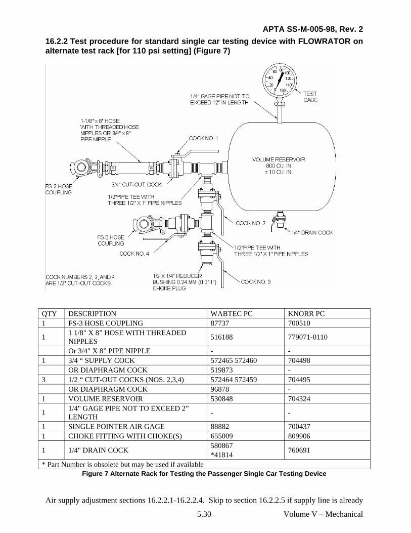
16.2.2 Test procedure for standard single car testing device with FLOWRATOR on alternate test rack [for 110 psi setting] (Figure 7)
QTY DESCRIPTION WABTEC PC KNORR PC 1 FS-3 HOSE COUPLING 87737 700510
1 1 1/8" X 8” HOSE WITH THREADED NIPPLES 516188 779071-0110
Or 3/4" X 8” PIPE NIPPLE - - 1 3/4 “ SUPPLY COCK 572465 572460 704498 OR DIAPHRAGM COCK 519873 - 3 1/2 “ CUT-OUT COCKS (NOS. 2,3,4) 572464 572459 704495 OR DIAPHRAGM COCK 96878 - 1 VOLUME RESERVOIR 530848 704324
1 1/4" GAGE PIPE NOT TO EXCEED 2” LENGTH - -
1 SINGLE POINTER AIR GAGE 88882 700437 1 CHOKE FITTING WITH CHOKE(S) 655009 809906
1 1/4" DRAIN COCK 580867 *41814 760691
* Part Number is obsolete but may be used if available Figure 7 Alternate Rack for Testing the Passenger Single Car Testing Device
Air supply adjustment sections 16.2.2.1-16.2.2.4. Skip to section 16.2.2.5 if supply line is already
APTA SS-M-005-98, Rev. 2
Volume V - Mechanical 5.31
regulated.
16.2.2.1. Attached supply line to test rack volume reservoir coupling (Figure 7). The air supply shall meet the requirements as specified in SECTION 4.1.2.1.
16.2.2.2. Open the supply cock and cock 1. Adjust the supply regulating valve to close at a minimum of 120 psi, maximum of 125 psi, as indicated by the test gage. (It is recommended that this regulating valve setting be at 120 psi).
NOTE: If the pressure indicated on the test rack volume reservoir gage should rise above 125 psi, the volume reservoir drain cock should be opened to release air currently trapped in the system. While the drain cock is open, the reducing valve should be turned down below the set pressure. Once the reducing valve set point has been turned back down, close the drain cock, and readjust the reducing valve. The pressure setting of the reducing valve shall be set by increasing to the set pressure and never by decreasing to the set pressure.
16.2.2.3. Close supply cock and slowly open reservoir drain cock and reduce test rack volume reservoir pressure to zero psi.
16.2.2.4. Disconnect supply line from volume reservoir coupling and close the reservoir drain cock.
16.2.2.5. Attach the FLOWRATOR end of the Device to the volume reservoir coupling of the test rack (Figure 7) then couple the supply line to the Device end with regulating valve. Open the supply cock and Cock 1. Cycle the valve several times by moving the device handle from Position No.1 to Position No. 6, finally leaving the handle in Position No. 1.
16.2.2.6. Verify the Device reducing valve is set to close at 110 psi as indicated by the operating reservoir gage. If the Device reducing valve does not close at 110 psi adjust the valve to properly close at 110 psi.
NOTE: If the pressure indicated on the test rack volume reservoir gage should rise above 110 psi, the Device 3/8” cock should be opened to release air currently trapped in the system. While the Device 3/8” cock is open, the reducing valve should be turned down below the set pressure. Once the reducing valve set point has been turned back down, close the Device 3/8” cock, and readjust the reducing valve. The pressure setting of the Device reducing valve shall be set by increasing to the set pressure and never by decreasing to the set pressure.
16.2.2.7. Move the Device handle to Position No. 6 and allow the test rack volume reservoir to decrease to 0 psi. and then move the Device handle to Position No. 3 (Lap). Close Cock 1 and with Cocks 2, 3, and 4 closed, open the Device 3/8" cock. Coat the opening of the 3/8" cock with soap suds to detect rotary valve leakage to brake pipe. Leakage must not exceed a 1” bubble in 5 seconds.
16.2.2.8. Close the 3/8" cock and move the Device handle to Position No. 6, then coat the Device exhaust port with soap suds in Position No.’s 6, 5, 4, 3, 2 and 1 consecutively. Leakage must not exceed a 1” bubble in 5 seconds.
16.2.2.9. With the Device handle in Position No. 1, open Cock 1. After reservoir is charged to
APTA SS-M-005-98, Rev. 2
Volume V - Mechanical 5.32
110 psi, compare VOLUME RESERVOIR and DEVICE gages and note that gage hands register within ½ psi.
16.2.2.10. FLOWRATOR Ball Test
a) Close the FLOWRATOR by-pass cock. There should be no indication of air flow. Open the FLOWRATOR by-pass cock and open Cocks 2 and 3, allowing air to vent through the choke fitting (or chokes) of the test rack.
b) Then close the FLOWRATOR by-pass cock. The ball should rise and float in the tube in the zone between the 110 psi condemning line and the top of the tube.
NOTE: If the FLOWRATOR fails to pass this test, the ball and glass tube of the FLOWRATOR should be cleaned, using a non-residue-producing solution to remove any oil or foreign matter which may be carried into the Device. When tube is properly installed in FLOWRATOR cock, the dot on the tube should be below the condemning line.
16.2.2.11. Close cocks 2 and 3, and open FLOWRATOR by-pass cock.
WAIT A MINIMUM OF 45 SECONDS BEFORE COMMENCING EACH OF THE FOLLOWING TESTS
16.2.2.12. Move the Device handle to Position No. 4 and reduce the volume reservoir pressure to approximately 30 psi. Move the Device handle to Position 2. Note that the operating reservoir charges from 40 to 50 psi in 21.5 to 28.5 seconds. At the completion of test, move the Device handle to Position No. 1 and charge the reservoir to 110 psi.
a) Move the Device handle to Position No. 4. The volume reservoir pressure shall reduce from 100 to 50 psi in 35 to 41 seconds. At the completion of test, move the Device handle to Position No. 1 and recharge to 110 psi.
b) Move the Device handle to Position No. 5. The volume reservoir pressure shall reduce from 100 to 40 psi in 10 to 13 seconds. At the completion of test, move the Device handle to Position No. 1 and recharge to 110 psi.
c) Move the Device handle to Position No. 6. The volume reservoir pressure shall reduce from 110 to 40 psi in 3 to 6 seconds with the handle movement. At the completion of test, move the Device handle to Position No. 1 and recharge to 110 psi.
d) Move the Device handle to Position No. 3 (Lap). Open the Device 3/8" cock and observe on the operating reservoir gage that the operating reservoir pressure reduces from 110 to 20 psi in 1.5 to 2.25 seconds.
e) At the completion of test, close the supply cock. Open the Device 3/8” cock, allow the Gage to decrease to zero psi and close the Device 3/8” cock. Remove the Device from the test rack.
NOTE: If the measured times are long, check for the proper choke size.
16.2.3 Test procedure for single car testing device with FLOWRATOR on standard test rack [for 90 psi setting] (Figure 6)
APTA SS-M-005-98, Rev. 2
Volume V - Mechanical 5.33
16.2.3.1. Attach the Device to rack as illustrated by Figure 6. Open the supply cock, cock 1, cock 2 and FLOWRATOR by-pass cock. Move the Device handle in Position No. 1. Adjust the test rack regulating valve to close at 100 psi as indicated on the test rack supply reservoir gage.
NOTE: If the pressure indicated on the test rack supply reservoir gage should rise above 100 psi, the Device 3/8” cock should be opened to release air currently trapped in the system. While the Device 3/8” cock is open, the reducing or feed valve should be turned down below the set pressure. Once the test rack feed valve or the Device reducing valve set point has been turned back down, close the Device 3/8” cock, and readjust the feed or reducing valve. The pressure setting of either the Device reducing valve or the test rack feed valve shall be set by increasing to the set pressure and never by decreasing to the set pressure.
16.2.3.2. Verify the Device reducing valve is set to close at 90 psi as indicated by the operating reservoir gage. If the Device reducing valve does not close at 90 psi adjust the valve to properly close at 90 psi.
NOTE: If the pressure indicated on the test rack operating reservoir gage should rise above 90 psi, the Device 3/8” cock should be opened to release air currently trapped in the system. While the Device 3/8” cock is open, the reducing valve should be turned down below the set pressure. Once the reducing valve set point has been turned back down, close the Device 3/8” cock, and readjust the reducing valve. The pressure setting of the Device reducing valve shall be set by increasing to the set pressure and never by decreasing to the set pressure.
16.2.3.3. Operate the Device several times by moving the Device handle from Position No. 1 to Position No. 6, finally leaving the handle in Position No. 3 (Lap).
16.2.3.4. Close Cock 1, and open the Device 3/8” cock until the operating reservoir gage indicates zero psi. Close the Device 3/8” cock.
16.2.3.5. Commence test with all numbered cocks closed and the Device handle in Position No. 3 (Lap). Open Cock 1 and the Device 3/8" cock. Coat the opening of the 3/8" cock with soap suds in order to detect rotary valve leakage to brake pipe. Leakage must not exceed a 1” bubble in 5 seconds.
16.2.3.6. Close the 3/8" cock and move the Device handle to Position No. 6, then coat the Device exhaust port with soap suds in Position No.’s 6, 5, 4, 3, 2 and 1 consecutively. Leakage must not exceed a 1” bubble in 5 seconds.
16.2.3.7. Open cock 2, and when operating reservoir pressure reaches 38 psi, move the Device handle to Position No. 2. Note that the operating reservoir charges from 40 to 45 psi in 28 to 33 seconds.
16.2.3.8. Close FLOWRATOR by-pass cock and move the Device handle to Position No. 1. Note that operating reservoir charges from 50 to 80 psi in 20 to 25 seconds.
16.2.3.9. Open the FLOWRATOR by-pass cock. After the operating reservoir is charged to 90 psi, compare OPERATING and DEVICE gages and note that the gage hands shall register within ½ psi.
16.2.3.10. FLOWRATOR Ball Test.
a) Close the FLOWRATOR by-pass cock. There should be no indication of air flow.
APTA SS-M-005-98, Rev. 2
Volume V - Mechanical 5.34
Open the FLOWRATOR by-pass cock and open Cocks 3 and 4, allowing air to vent through the choke fitting (or chokes) of the test rack.
b) Then close the FLOWRATOR by-pass cock. The ball should rise and float in the tube in the zone between the condemning line and the top of the tube.
NOTE: If the FLOWRATOR fails to pass this test, the ball and glass tube of the FLOWRATOR should be cleaned, using a non-residue-producing solution to remove any oil or foreign matter which may be carried into the Device. When tube is properly installed in FLOWRATOR cock, the dot on the tube should be below the condemning line.
16.2.3.11. Close Cock 3 and open the FLOWRATOR by-pass cock.
WAIT A MINIMUM OF 45 SECONDS BEFORE COMMENCING EACH OF THE FOLLOWING TESTS
a) Move the Device handle to Position No. 4. The operating reservoir pressure shall reduce from 80 to 70 psi in 11-1/2 to 14-1/2 seconds. At the completion of test, move the Device handle to Position 1 and recharge to 90 psi.
b) Move the Device handle to Position No. 5. The operating reservoir pressure shall reduce from 80 to 40 psi in 14-1/2 to 17-1/2 seconds. At the completion of test, move the Device handle to Position No. 1 and recharge to 90 psi.
c) Move the Device handle to Position No. 6. The operating reservoir pressure shall reduce from 80 to 30 psi in 6 to 9-1/2 seconds. At the completion of test, move the Device handle to Position No. 1 and recharge to 90 psi.
d) Move the Device handle to Position No. 3 (Lap). Open the Device 3/8" cock and observe on the operating reservoir gage that the operating reservoir pressure reduces from 90 to 20 psi in 3 to 3-1/2 seconds.
e) At the completion of test, close Cock 1, open the Device 3/8” cock and allow the Device Gage to decrease to zero psi. Close the Device 3/8” cock and close the remaining test rack cocks. Remove the Device from the test rack.
16.2.4 Test procedure for standard single car testing device with FLOWRATOR on alternate test rack [For 90 psi setting] (Figure 7)
Air supply adjustment sections 16.2.2.1-16.2.2.4. Skip to section 16.2.2.5 if supply line is already regulated.
16.2.4.1. With all cocks closed, attach supply line to test rack volume reservoir coupling (Figure 7). The air supply shall meet the requirements as specified in SECTION 4.1.2.1.
16.2.4.2. Open the supply cock and/ cock 1. Adjust the supply regulating valve to close at 100 psi as indicated by the test gage.
NOTE: If the pressure indicated on the test rack volume reservoir gage should rise above 100 psi, the volume reservoir drain cock should be opened to release air currently trapped in the system. While the drain cock is open, the reducing valve should be turned down below the set pressure. Once the reducing valve set point has been turned back down, close the drain cock, and readjust the reducing valve. The pressure setting of the reducing valve shall be set by increasing to the set pressure and never by decreasing to the set pressure.
APTA SS-M-005-98, Rev. 2
Volume V - Mechanical 5.35
16.2.4.3. Close supply cock and slowly open reservoir drain cock and reduce test rack volume reservoir pressure to zero psi.
16.2.4.4. Disconnect supply line from volume reservoir coupling. Close volume reservoir drain cock.
16.2.4.5. Attach the FLOWRATOR end of the Device to the volume reservoir coupling of the test rack (Figure 7) then couple the supply line to the Device end with regulating valve.
16.2.4.6. Open the supply cock, cock 1 and FLOWRATOR by-pass cock. Move the Device handle to Position No. 1.
16.2.4.7. Verify the Device reducing valve, if so equipped, is set to close at 90 psi as indicated by the operating reservoir gage. If the Device reducing valve does not close at 90 psi adjust the valve to properly close at 90 psi.
NOTE: If the pressure indicated on the test rack operating reservoir gage should rise above 90 psi, the Device 3/8” cock should be opened to release air currently trapped in the system. While the Device 3/8” cock is open, the reducing valve should be turned down below the set pressure. Once the reducing valve set point has been turned back down, close the Device 3/8” cock, and readjust the reducing valve. The pressure setting of the Device reducing valve shall be set by increasing to the set pressure and never by decreasing to the set pressure.
16.2.4.8. Move the Device handle to Position No. 6 and allow the volume reservoir gage to decrease to 0 psi and then move Device handle to Position No. 3 (Lap). Close Cock 1 and open the Device 3/8" cock. Coat the opening of the 3/8" cock with soap suds to detect rotary valve leakage to brake pipe. Leakage must not exceed a 1” bubble in 5 seconds.
16.2.4.9. Close the 3/8" cock and move the Device handle to Position No. 6, then coat the Device exhaust port with soap suds in Position No.’s 6, 5, 4, 3, 2 and 1 consecutively. Leakage must not exceed a 1” bubble in 5 seconds.
16.2.4.10. With the Device handle in Position No. 1, open Cock 1. After reservoir is charged to 90 psi, compare VOLUME RESERVOIR and DEVICE gages and note that gage hands register within ½ psi.
16.2.4.11. FLOWRATOR Ball Test
a) Close the FLOWRATOR by-pass cock. There should be no indication of airflow. Open the FLOWRATOR by-pass cock and open Cocks 2 and 3, allowing air to vent through the choke fitting (or chokes) of the test rack.
b) Then close the FLOWRATOR by-pass cock. The ball should rise and float in the tube in the zone between the condemning line and the top of the tube.
NOTE: If the FLOWRATOR fails to pass this test, the ball and glass tube of the FLOWRATOR should be cleaned, using a non-residue-producing solution to remove any oil or foreign matter which may be carried into the Device. When tube is properly installed in FLOWRATOR cock, the dot on the tube should be below the condemning line.
APTA SS-M-005-98, Rev. 2
Volume V - Mechanical 5.36
16.2.4.12. Close cocks 2 and 3, and open FLOWRATOR by-pass cock.
WAIT A MINIMUM OF 45 SECONDS BEFORE COMMENCING EACH OF THE FOLLOWING TESTS
16.2.4.13. Move the Device handle to Position No. 4 and reduce the volume reservoir pressure to approximately 30 psi. Move the Device handle to Position 2. Note that the operating reservoir charges from 40 to 50 psi in 27 to 33 seconds. At the completion of test, move the Device handle to Position No. 1 and charge the reservoir to 90 psi.
a) Move the Device handle to Position No. 4. The volume reservoir pressure shall reduce from 80 to 50 psi in 24 to 26 seconds. At the completion of test, move the Device handle to Position No. 1 and recharge to 90 psi.
b) Move the Device handle to Position No. 5. The volume reservoir pressure shall reduce from 80 to 40 psi in 7-1/2 to 9-1/2 seconds. At the completion of test, move the Device handle to Position No. 1 and recharge to 90 psi.
c) Move the Device handle to Position No. 6. The volume reservoir pressure shall reduce from 80 to 20 psi in 4 to 7 seconds. At the completion of test, move the Device handle to Position No. 1 and recharge to 90 psi.
d) Move the Device handle to Position No. 3 (Lap). Open the Device 3/8" cock and observe on the operating reservoir gage that the operating reservoir pressure reduces from 90 to 20 psi in 1-1/2 to 2 seconds.
e) At the completion of test, close the supply cock. Open the Device 3/8” cock, allow the Gage to decrease to zero psi and close the Device 3/8” cock. Remove the Device from the test rack.
16.2.5 Test procedure for single car testing device test coupling standard test rack (Figure 6)
16.2.5.1. Move the device handle to position 1, open cocks 1 and 2, and open the FLOWRATOR by-pass cock.
a) Close cocks 4 and 5.
b) Open cock 3.
16.2.5.2. Attach the test coupling to the FS-3 hose coupling located after cock 5.
a) Charge the volume reservoir to 110 psi and wait 1 minute.
b) Move the device handle to position 3 and with the FLOWRATOR by-pass open, open cock 5 and observe that the volume reservoir gauge reduces from 106 to 101 psi within 2 minutes 10 seconds to 2 minutes 29 seconds.
c) Close cock 3 and wait until flow of air from the .24-mm choke fitting stops.
APTA SS-M-005-98, Rev. 2
Volume V - Mechanical 5.37
d) Close cock 5 and remove the test coupling.
16.2.5.3. If the choke fitting fails this test, carefully replace the filter and blow the choke clean. Do not use metal tools to clean the choke. An appropriate cleaning solution may be used as needed. Once the choke is cleaned or replaced, repeat SECTION 16.2.5.
16.2.6 Test procedure for single car testing device test coupling alternate test rack (Figure 7)
16.2.6.1. Move the device handle to position 1, open cock 1 and open the FLOWRATOR by-pass cock.
a) Close cocks 3 and 4.
b) Open cock 2.
c) Attach the FLOWRATOR end of the Device to the volume reservoir coupling of the test rack (Figure 7) then couple the supply line to the Device end with regulating valve. The air supply shall meet the requirements as specified in SECTION 4.1.2.1.
16.2.6.2. Attach the test coupling to the FS-3 hose coupling located after cock 4.
a) Charge the volume reservoir to 110 psi and wait 1 minute.
b) Move the device handle to position 3 and with the FLOWRATOR by-pass open, open cock 4 and observe that the volume reservoir gauge reduces from 106 to 101 psi within 1 minute 9 seconds to 1 minute 20 seconds.
c) Close cock 2 and wait until flow of air from the .24-mm choke fitting stops.
d) Close cock 4 and remove the test coupling
16.2.6.3. If the choke fitting fails this test, carefully replace the filter and blow the choke clean. Do not use metal tools to clean the choke. An appropriate cleaning solution may be used as needed. Once the choke is cleaned or replaced, repeat SECTION 16.2.6.
![[XLS]tax.vermont.govtax.vermont.gov/sites/tax/files/documents/SPAN Data List... · Web view015-005-10947 015-005-10091 015-005-11649 015-005-10773 015-005-11222 015-005-10889 015-005-11109](https://img.pdfslide.net/doc/110x75/5ac161e67f8b9a5a4e8d129a/xlstax-data-listweb-view015-005-10947-015-005-10091-015-005-11649-015-005-10773.jpg)


![[XLS] · Web view118 118 45 45 88 118 118 128 128 128 128 98 98 12 12 12 98 98 98 88 98 58 128 128 98 98 98 98 98 98 98 98 12 12 98 98 98 98 12 98 98 98 58 12 98 98 98 98 98 98 98](https://img.pdfslide.net/doc/110x75/5b1aab787f8b9a1e258df5af/xls-web-view118-118-45-45-88-118-118-128-128-128-128-98-98-12-12-12-98-98.jpg)

![[005-2016-MINEDU]-[18-03-2016 12_19_52]-005-Convenio N° 005-2016-MINEDU](https://img.pdfslide.net/doc/110x75/577c7d821a28abe0549f0579/005-2016-minedu-18-03-2016-121952-005-convenio-n-005-2016-minedu.jpg)
