Embed Size (px)
Citation preview
Design of Steel Structures Prof. S.R.Satish Kumar and Prof. A.R.Santha Kumar
Indian Institute of Technology Madras
5. COMPRESSION MEMBERS
5.1 Introduction
Column, top chords of trusses, diagonals and bracing members are all examples
of compression members. Columns are usually thought of as straight compression
members whose lengths are considerably greater than their cross-sectional
dimensions.
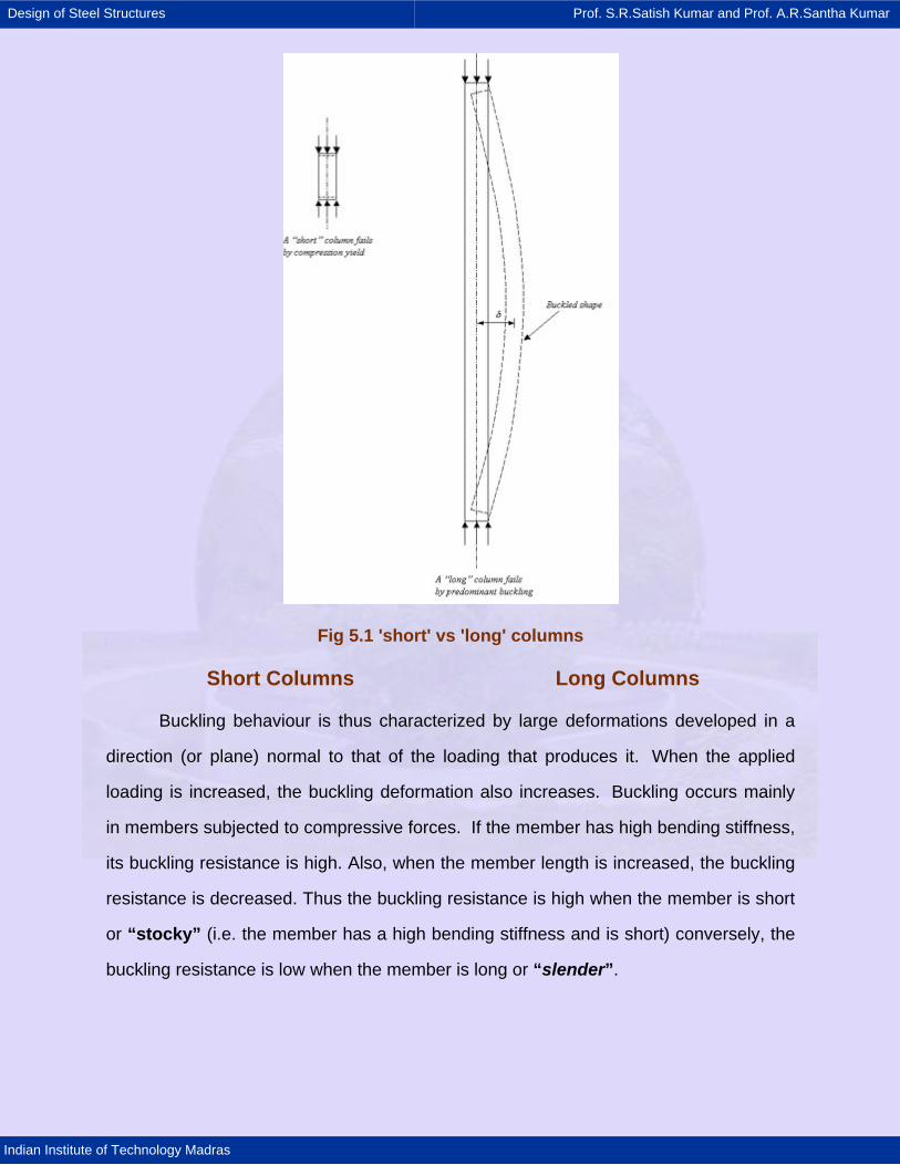
An initially straight strut or column, compressed by gradually increasing equal
and opposite axial forces at the ends is considered first. Columns and struts are termed
“long” or “short” depending on their proneness to buckling. If the strut is “short”, the
applied forces will cause a compressive strain, which results in the shortening of the
strut in the direction of the applied forces. Under incremental loading, this shortening
continues until the column yields or "squashes". However, if the strut is “long”, similar
axial shortening is observed only at the initial stages of incremental loading. Thereafter,
as the applied forces are increased in magnitude, the strut becomes “unstable” and
develops a deformation in a direction normal to the loading axis and its axis is no longer
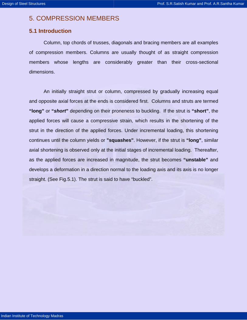
straight. (See Fig.5.1). The strut is said to have “buckled”.
Design of Steel Structures Prof. S.R.Satish Kumar and Prof. A.R.Santha Kumar
Indian Institute of Technology Madras
Fig 5.1 'short' vs 'long' columns
Short Columns Long Columns
Buckling behaviour is thus characterized by large deformations developed in a
direction (or plane) normal to that of the loading that produces it. When the applied
loading is increased, the buckling deformation also increases. Buckling occurs mainly
in members subjected to compressive forces. If the member has high bending stiffness,
its buckling resistance is high. Also, when the member length is increased, the buckling
resistance is decreased. Thus the buckling resistance is high when the member is short
or “stocky” (i.e. the member has a high bending stiffness and is short) conversely, the
buckling resistance is low when the member is long or “slender”.
Design of Steel Structures Prof. S.R.Satish Kumar and Prof. A.R.Santha Kumar
Indian Institute of Technology Madras
Structural steel has high yield strength and ultimate strength compared with other
construction materials. Hence compression members made of steel tend to be slender
compared with reinforced concrete or prestressed concrete compression members.
Buckling is of particular interest while employing slender steel members. Members
fabricated from steel plating or sheeting and subjected to compressive stresses also
experience local buckling of the plate elements. This chapter introduces buckling in the
context of axially compressed struts and identifies the factors governing the buckling
behaviour. Both global and local buckling is instability phenomena and should be
avoided by an adequate margin of safety.
Traditionally, the design of compression members was based on Euler analysis
of ideal columns which gives an upper band to the buckling load. However, practical
columns are far from ideal and buckle at much lower loads. The first significant step in
the design procedures for such columns was the use of Perry Robertsons curves.
Modern codes advocate the use of multiple-column curves for design. Although these
design procedures are more accurate in predicting the buckling load of practical
columns, Euler's theory helps in the understanding of the behaviour of slender columns
and is reviewed in the following sections.
Design of Steel Structures Prof. S.R.Satish Kumar and Prof. A.R.Santha Kumar
Indian Institute of Technology Madras
5.10 Summary
In the previous sections, the behaviour of practical columns subjected to
axial compressive loading was discussed and the following conclusions were
drawn.
· Very short columns subjected to axial compression fail by yielding. Very long
columns fail by buckling in the Euler mode.
· Practical columns generally fail by inelastic buckling and do not conform to
the assumptions made in Euler theory. They do not normally remain linearly
elastic upto failure unless they are very slender
· Slenderness ratio (l/r) and material yield stress (fy) are dominant factors
affecting the ultimate strengths of axially loaded columns.
· The compressive strengths of practical columns are significantly affected by
(i) the initial imperfection (ii) eccentricity of loading (iii) residual stresses and (iv)
lack of distinct yield point and strain hardening. Ultimate load tests on practical
columns reveal a scatter band of results shown in Fig. 5.19. A lower bound curve
of the type shown therein can be employed for design purposes.
Design of Steel Structures Prof. S.R.Satish Kumar and Prof. A.R.Santha Kumar
Indian Institute of Technology Madras
5.11 Concluding remarks
The elastic buckling of an ideally straight column pin ended at both ends
and subjected to axial compression was considered. The elastic buckling load
was shown to be dependent on the slenderness ratio (/r) of the column. Factors
affecting the column strengths (viz. initial imperfection, eccentricity of loading,
residual stresses and lack of well-defined elastic limit) were all individually
considered. Finally a generalized column strength curve (taking account of all
these factors) has been suggested, as the basis of column design curves
employed in Design Practices. The concept of “effective length” of the column
has been described, which could be used as the basis of design of columns with
differing boundary conditions.
The phenomenon of Elastic Torsional and Torsional-flexural buckling of a
perfect column were discussed conceptually. The instability effects due to
torsional buckling of slender sections are explained and discussed.
Design of columns using multiple column curves as given in the code; was
discussed. Built-up fabricated members frequently employed (when rolled
sections are found inadequate) were discussed in detail. Design guidance is
provided for laced/battened columns. Steps in the design of axially loaded
column were listed.
Design of Steel Structures Prof. S.R.Satish Kumar and Prof. A.R.Santha Kumar
Indian Institute of Technology Madras
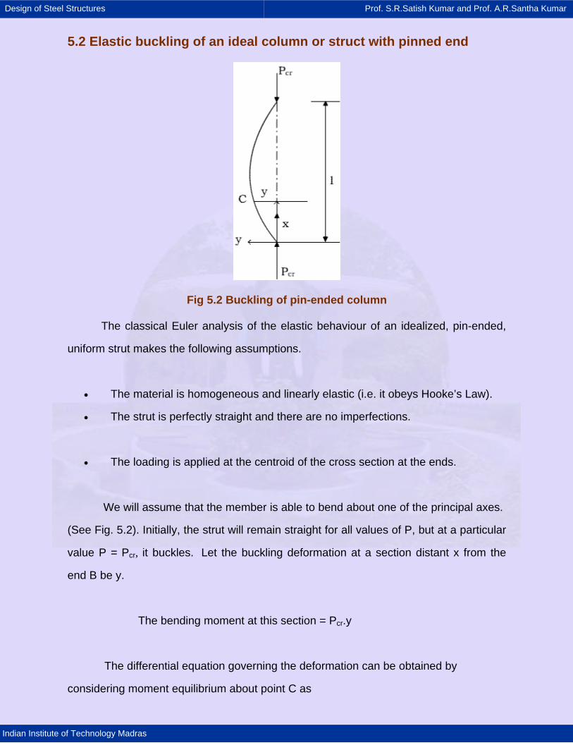
5.2 Elastic buckling of an ideal column or struct with pinned end
Fig 5.2 Buckling of pin-ended column
The classical Euler analysis of the elastic behaviour of an idealized, pin-ended,
uniform strut makes the following assumptions.
• The material is homogeneous and linearly elastic (i.e. it obeys Hooke’s Law).
• The strut is perfectly straight and there are no imperfections.
• The loading is applied at the centroid of the cross section at the ends.
We will assume that the member is able to bend about one of the principal axes.
(See Fig. 5.2). Initially, the strut will remain straight for all values of P, but at a particular
value P = Pcr, it buckles. Let the buckling deformation at a section distant x from the
end B be y.
The bending moment at this section = Pcr.y
The differential equation governing the deformation can be obtained by
considering moment equilibrium about point C as
Design of Steel Structures Prof. S.R.Satish Kumar and Prof. A.R.Santha Kumar
Indian Institute of Technology Madras
2
cr 2d yP y EI 0dx
+ = (5.1)
The general solution for this differential equation is given by
cr cr1 1
P Py A Cos x B Sin x
E1 E1= + (5.2)
Where A1 and B1 are constants.
Since y = 0 when x = 0, A1 = 0.
Also y = 0 when x = L gives
cr1
PB Sin L 0
E1=
Thus, either B1 = 0 or cr1
PB Sin L 0
E1=
B1 = 0 means y = 0 for all values of x (i.e. the column remains straight).
Alternatively
This equation is satisfied only when
cr
2 2 2 2
cr 2 2 2
PL 0, , 2 ,..........
E1This gives
EI 4 EI n EIp , ,.........L L L
= π π
π π π=
(5.3)
Where n is any integer.
Design of Steel Structures Prof. S.R.Satish Kumar and Prof. A.R.Santha Kumar
Indian Institute of Technology Madras
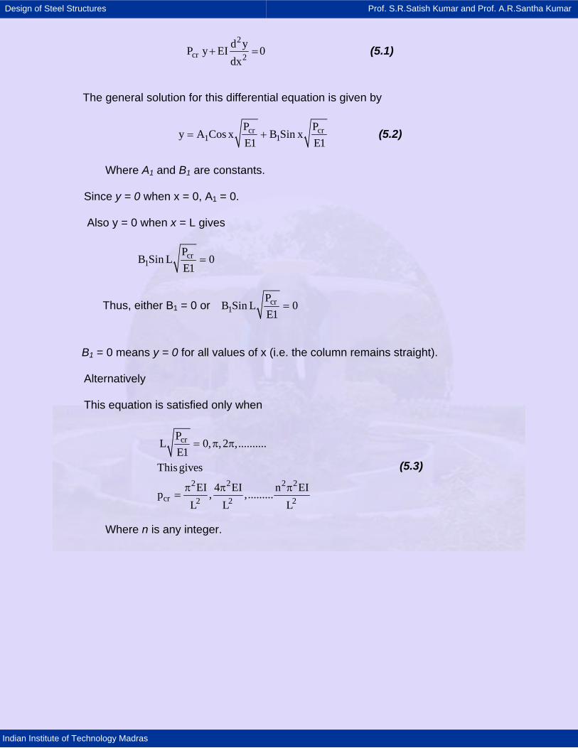
Fig 5.3 Buckling load Vs centre lateral deflection relationship
While there are several buckling modes each corresponding to n = 1, 2, 3…
(See Fig. 5.3) the lowest stable buckling mode corresponds to n = 1.
The lowest value of the critical load (i.e. the load causing buckling) is given by
2
cr 2EIp
Lπ
= (5.4)
Thus the Euler buckling analysis for a “straight" strut; will lead to the following
conclusions:
1. The strut can remain straight for any value of P.
2. Under incremental loading, when P reaches a value of Pcr = π2EI / L2 the
strut can buckle in the shape of a half-sine wave; the amplitude
of this buckling deflection is indeterminate.
3. At higher values of the loads given by n2π2EI / L2 other sinusoidal buckled
shapes (n half waves) are possible. However, it is possible to show that the column will
be in unstable equilibrium for all values of P > π2EI / L2 whether it be straight or buckled.
This means that the slightest disturbance will cause the column to deflect away from its
Design of Steel Structures Prof. S.R.Satish Kumar and Prof. A.R.Santha Kumar
Indian Institute of Technology Madras
original position. Elastic Instability may be defined in general terms as a condition in
which the structure has no tendency to return to its initial position when
slightly disturbed, even when the material is assumed to have an infinitely large yield
stress. Thus Pcr = π2EI / L2 represents the maximum load that the strut can usefully
support.
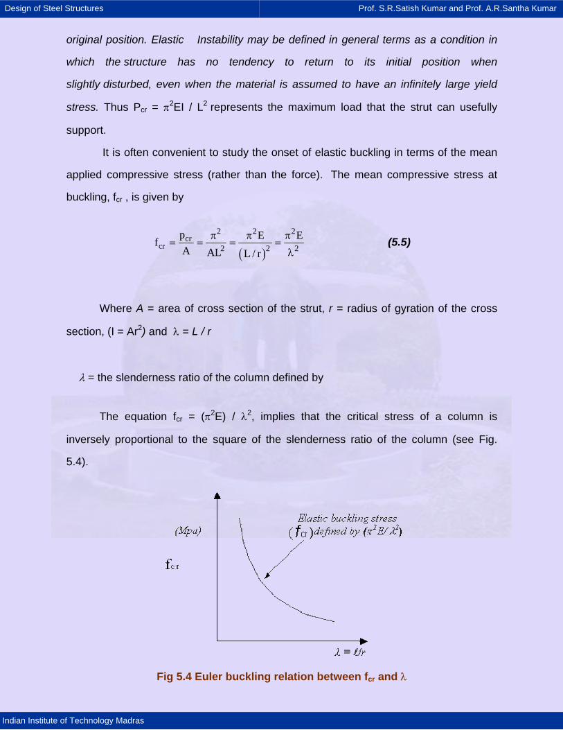
It is often convenient to study the onset of elastic buckling in terms of the mean
applied compressive stress (rather than the force). The mean compressive stress at
buckling, fcr , is given by
( )
2 2 2cr
cr 2 2 2p E EfA AL L / r
π π π= = = =
λ (5.5)
Where A = area of cross section of the strut, r = radius of gyration of the cross
section, (I = Ar2) and λ = L / r
λ = the slenderness ratio of the column defined by
The equation fcr = (π2E) / λ2, implies that the critical stress of a column is
inversely proportional to the square of the slenderness ratio of the column (see Fig.
5.4).
Fig 5.4 Euler buckling relation between fcr and λ
Design of Steel Structures Prof. S.R.Satish Kumar and Prof. A.R.Santha Kumar
Indian Institute of Technology Madras
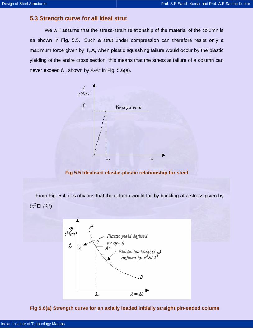
5.3 Strength curve for all ideal strut
We will assume that the stress-strain relationship of the material of the column is
as shown in Fig. 5.5. Such a strut under compression can therefore resist only a
maximum force given by fy.A, when plastic squashing failure would occur by the plastic
yielding of the entire cross section; this means that the stress at failure of a column can
never exceed fy , shown by A-A1 in Fig. 5.6(a).
Fig 5.5 Idealised elastic-plastic relationship for steel
From Fig. 5.4, it is obvious that the column would fail by buckling at a stress given by
(π2 EI / λ2)
Fig 5.6(a) Strength curve for an axially loaded initially straight pin-ended column
Design of Steel Structures Prof. S.R.Satish Kumar and Prof. A.R.Santha Kumar
Indian Institute of Technology Madras
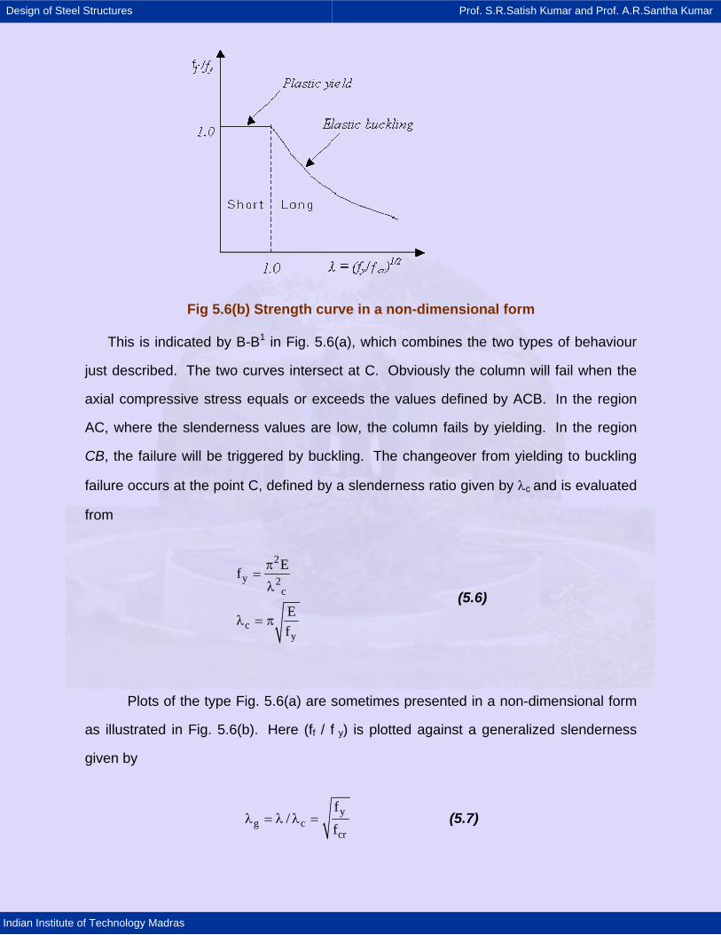
Fig 5.6(b) Strength curve in a non-dimensional form
This is indicated by B-B1 in Fig. 5.6(a), which combines the two types of behaviour
just described. The two curves intersect at C. Obviously the column will fail when the
axial compressive stress equals or exceeds the values defined by ACB. In the region
AC, where the slenderness values are low, the column fails by yielding. In the region
CB, the failure will be triggered by buckling. The changeover from yielding to buckling
failure occurs at the point C, defined by a slenderness ratio given by λc and is evaluated
from
2
y 2c
cy
Ef
Ef
π=λ
λ = π
(5.6)
Plots of the type Fig. 5.6(a) are sometimes presented in a non-dimensional form
as illustrated in Fig. 5.6(b). Here (ff / f y) is plotted against a generalized slenderness
given by
yg c
cr
f/
fλ = λ λ = (5.7)

Design of Steel Structures Prof. S.R.Satish Kumar and Prof. A.R.Santha Kumar
Indian Institute of Technology Madras
This single plot can be employed to define the strength of all axially loaded,
initially straight columns irrespective of their E and fy values. The change over from
plastic yield to elastic critical buckling failure occurs when λg = 1 ( i.e when fy = σcr ), the
corresponding slenderness ratio is π √E / fy . This slenderness ratio demarcates short
and long columns.
Design of Steel Structures Prof. S.R.Satish Kumar and Prof. A.R.Santha Kumar
Indian Institute of Technology Madras
5.4 Strength of compression members in practice
The highly idealized straight form assumed for the struts considered so far
cannot be achieved in practice. Members are never perfectly straight and they can
never be loaded exactly at the centroid of the cross section. Deviations from the ideal
elastic plastic behaviour defined by Fig. 5 are encountered due to strain hardening at
high strains and the absence of clearly defined yield point in some steel. Moreover,
residual stresses locked-in during the process of rolling also provide an added
complexity.
Thus the three components, which contribute to a reduction in the actual strength
of columns (compared with the predictions from the “ideal” column curve) are
(i) Initial imperfection or initial bow.
(ii) Eccentricity of application of loads.
(iii) Residual stresses locked into the cross section.
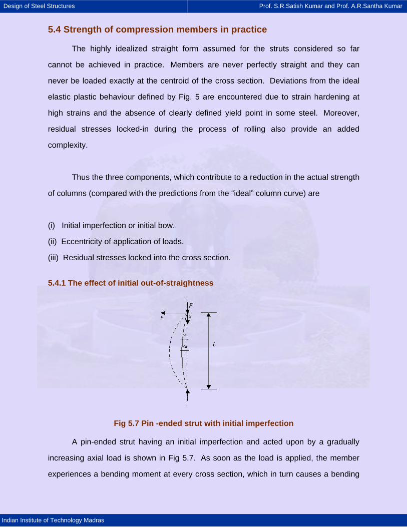
5.4.1 The effect of initial out-of-straightness
Fig 5.7 Pin -ended strut with initial imperfection
A pin-ended strut having an initial imperfection and acted upon by a gradually
increasing axial load is shown in Fig 5.7. As soon as the load is applied, the member
experiences a bending moment at every cross section, which in turn causes a bending
Design of Steel Structures Prof. S.R.Satish Kumar and Prof. A.R.Santha Kumar
Indian Institute of Technology Madras
deformation. For simplicity of calculations, it is usual to assume the initial shape of the
column defined by
0 0
xy a sinl
π= (5.8)
where ao is the maximum imperfection at the centre, where x = l / 2. Other
initial shapes are, of course, possible, but the half sine-wave assumed above
corresponding to the lowest mode shape, represents the greatest influence on the
actual behaviour, and hence is adequate.
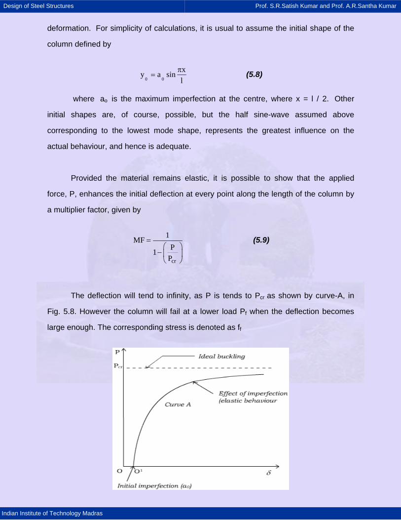
Provided the material remains elastic, it is possible to show that the applied
force, P, enhances the initial deflection at every point along the length of the column by
a multiplier factor, given by
cr
1MFP1
P
=⎛ ⎞
− ⎜ ⎟⎝ ⎠
(5.9)
The deflection will tend to infinity, as P is tends to Pcr as shown by curve-A, in
Fig. 5.8. However the column will fail at a lower load Pf when the deflection becomes
large enough. The corresponding stress is denoted as ff
Design of Steel Structures Prof. S.R.Satish Kumar and Prof. A.R.Santha Kumar
Indian Institute of Technology Madras
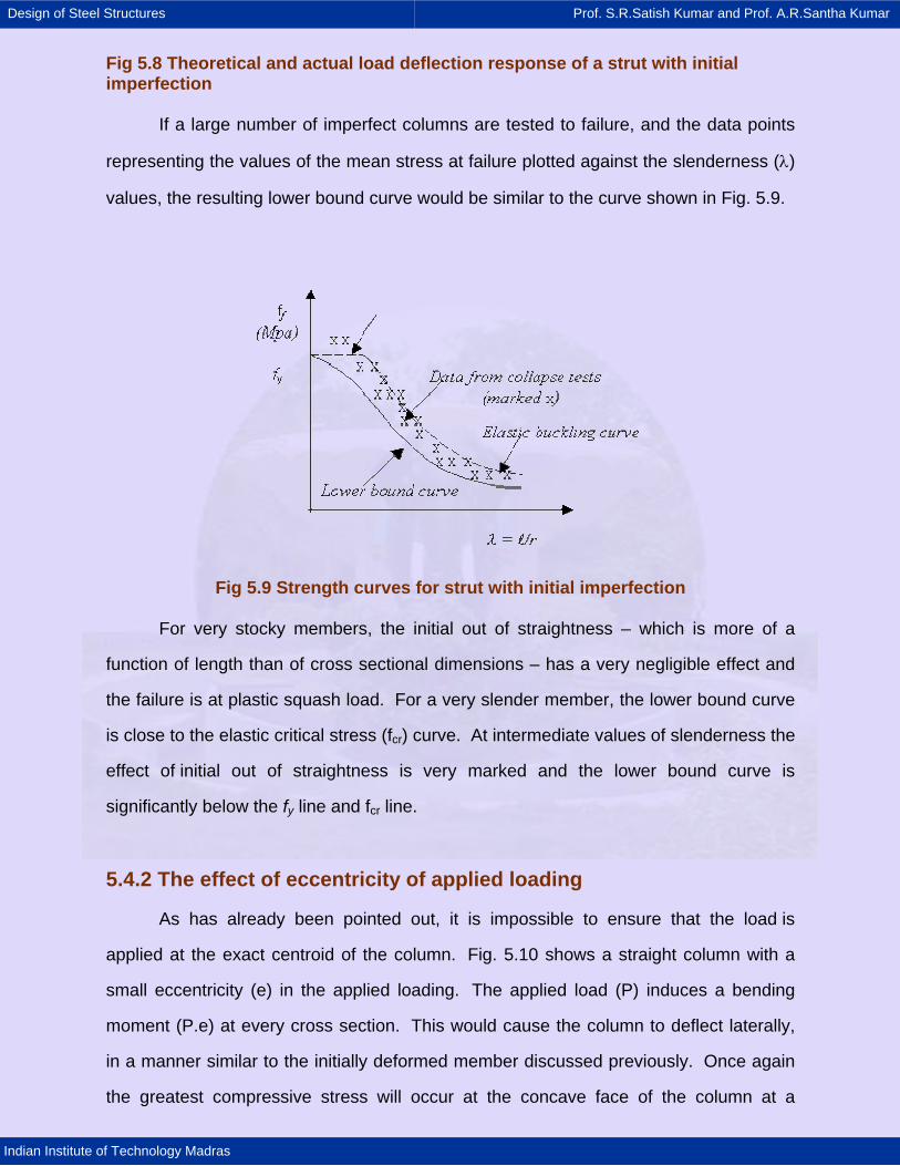
Fig 5.8 Theoretical and actual load deflection response of a strut with initial imperfection
If a large number of imperfect columns are tested to failure, and the data points
representing the values of the mean stress at failure plotted against the slenderness (λ)
values, the resulting lower bound curve would be similar to the curve shown in Fig. 5.9.
Fig 5.9 Strength curves for strut with initial imperfection
For very stocky members, the initial out of straightness – which is more of a
function of length than of cross sectional dimensions – has a very negligible effect and
the failure is at plastic squash load. For a very slender member, the lower bound curve
is close to the elastic critical stress (fcr) curve. At intermediate values of slenderness the
effect of initial out of straightness is very marked and the lower bound curve is
significantly below the fy line and fcr line.
5.4.2 The effect of eccentricity of applied loading
As has already been pointed out, it is impossible to ensure that the load is
applied at the exact centroid of the column. Fig. 5.10 shows a straight column with a
small eccentricity (e) in the applied loading. The applied load (P) induces a bending
moment (P.e) at every cross section. This would cause the column to deflect laterally,
in a manner similar to the initially deformed member discussed previously. Once again
the greatest compressive stress will occur at the concave face of the column at a
Design of Steel Structures Prof. S.R.Satish Kumar and Prof. A.R.Santha Kumar
Indian Institute of Technology Madras
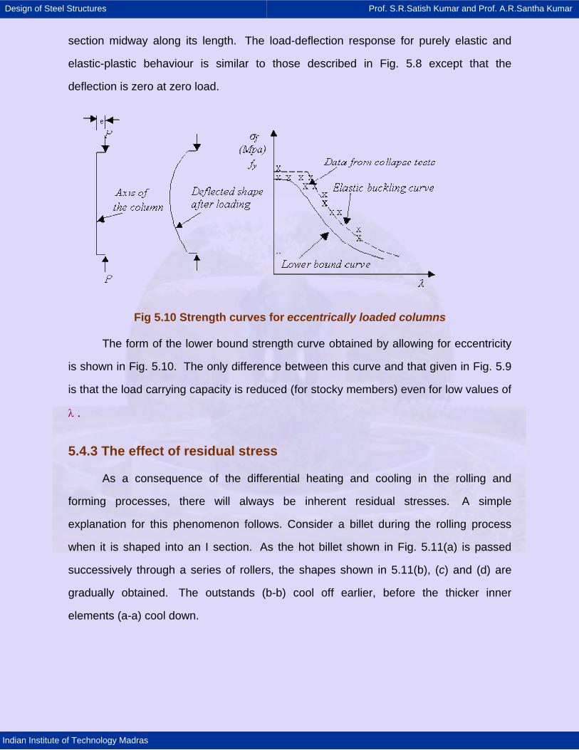
section midway along its length. The load-deflection response for purely elastic and
elastic-plastic behaviour is similar to those described in Fig. 5.8 except that the
deflection is zero at zero load.
Fig 5.10 Strength curves for eccentrically loaded columns
The form of the lower bound strength curve obtained by allowing for eccentricity
is shown in Fig. 5.10. The only difference between this curve and that given in Fig. 5.9
is that the load carrying capacity is reduced (for stocky members) even for low values of
λ .
5.4.3 The effect of residual stress
As a consequence of the differential heating and cooling in the rolling and
forming processes, there will always be inherent residual stresses. A simple
explanation for this phenomenon follows. Consider a billet during the rolling process
when it is shaped into an I section. As the hot billet shown in Fig. 5.11(a) is passed
successively through a series of rollers, the shapes shown in 5.11(b), (c) and (d) are
gradually obtained. The outstands (b-b) cool off earlier, before the thicker inner
elements (a-a) cool down.
Design of Steel Structures Prof. S.R.Satish Kumar and Prof. A.R.Santha Kumar
Indian Institute of Technology Madras
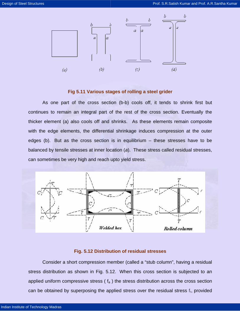
Fig 5.11 Various stages of rolling a steel grider
As one part of the cross section (b-b) cools off, it tends to shrink first but
continues to remain an integral part of the rest of the cross section. Eventually the
thicker element (a) also cools off and shrinks. As these elements remain composite
with the edge elements, the differential shrinkage induces compression at the outer
edges (b). But as the cross section is in equilibrium – these stresses have to be
balanced by tensile stresses at inner location (a). These stress called residual stresses,
can sometimes be very high and reach upto yield stress.
Fig. 5.12 Distribution of residual stresses
Consider a short compression member (called a “stub column”, having a residual
stress distribution as shown in Fig. 5.12. When this cross section is subjected to an
applied uniform compressive stress ( fa ) the stress distribution across the cross section
can be obtained by superposing the applied stress over the residual stress fr, provided
Design of Steel Structures Prof. S.R.Satish Kumar and Prof. A.R.Santha Kumar
Indian Institute of Technology Madras
the total stress nowhere reaches yield, the section continues to deform elastically.
Under incremental loading, the flange tips will yield first when [(fa + fr) = fy]. Under
further loading, yielding will spread inwards and eventually the web will also yield.
When fa = fy, the entire section will have yielded and the column will get squashed.
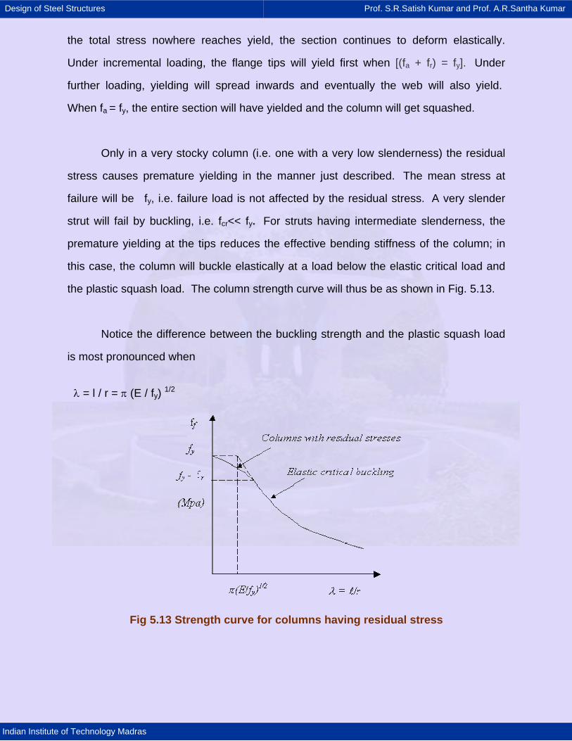
Only in a very stocky column (i.e. one with a very low slenderness) the residual
stress causes premature yielding in the manner just described. The mean stress at
failure will be fy, i.e. failure load is not affected by the residual stress. A very slender
strut will fail by buckling, i.e. fcr<< fy. For struts having intermediate slenderness, the
premature yielding at the tips reduces the effective bending stiffness of the column; in
this case, the column will buckle elastically at a load below the elastic critical load and
the plastic squash load. The column strength curve will thus be as shown in Fig. 5.13.
Notice the difference between the buckling strength and the plastic squash load
is most pronounced when
λ = l / r = π (E / fy) 1/2
Fig 5.13 Strength curve for columns having residual stress
Design of Steel Structures Prof. S.R.Satish Kumar and Prof. A.R.Santha Kumar
Indian Institute of Technology Madras
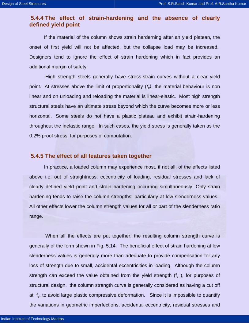
5.4.4 The effect of strain-hardening and the absence of clearly defined yield point
If the material of the column shows strain harderning after an yield platean, the
onset of first yield will not be affected, but the collapse load may be increased.
Designers tend to ignore the effect of strain hardening which in fact provides an
additional margin of safety.
High strength steels generally have stress-strain curves without a clear yield
point. At stresses above the limit of proportionality (fp), the material behaviour is non
linear and on unloading and reloading the material is linear-elastic. Most high strength
structural steels have an ultimate stress beyond which the curve becomes more or less
horizontal. Some steels do not have a plastic plateau and exhibit strain-hardening
throughout the inelastic range. In such cases, the yield stress is generally taken as the
0.2% proof stress, for purposes of computation.
5.4.5 The effect of all features taken together
In practice, a loaded column may experience most, if not all, of the effects listed
above i.e. out of straightness, eccentricity of loading, residual stresses and lack of
clearly defined yield point and strain hardening occurring simultaneously. Only strain
hardening tends to raise the column strengths, particularly at low slenderness values.
All other effects lower the column strength values for all or part of the slenderness ratio
range.
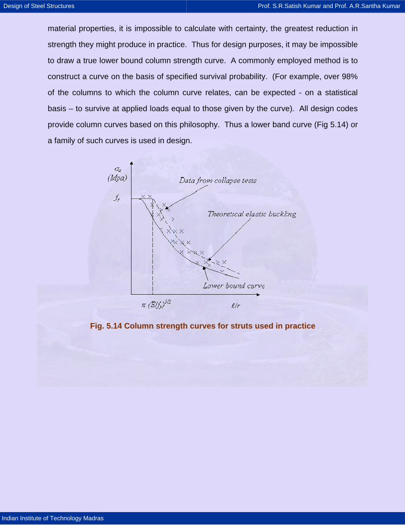
When all the effects are put together, the resulting column strength curve is
generally of the form shown in Fig. 5.14. The beneficial effect of strain hardening at low
slenderness values is generally more than adequate to provide compensation for any
loss of strength due to small, accidental eccentricities in loading. Although the column
strength can exceed the value obtained from the yield strength (fy ), for purposes of
structural design, the column strength curve is generally considered as having a cut off
at fy, to avoid large plastic compressive deformation. Since it is impossible to quantify
the variations in geometric imperfections, accidental eccentricity, residual stresses and
Design of Steel Structures Prof. S.R.Satish Kumar and Prof. A.R.Santha Kumar
Indian Institute of Technology Madras
material properties, it is impossible to calculate with certainty, the greatest reduction in
strength they might produce in practice. Thus for design purposes, it may be impossible
to draw a true lower bound column strength curve. A commonly employed method is to
construct a curve on the basis of specified survival probability. (For example, over 98%
of the columns to which the column curve relates, can be expected - on a statistical
basis – to survive at applied loads equal to those given by the curve). All design codes
provide column curves based on this philosophy. Thus a lower band curve (Fig 5.14) or
a family of such curves is used in design.
Fig. 5.14 Column strength curves for struts used in practice
Design of Steel Structures Prof. S.R.Satish Kumar and Prof. A.R.Santha Kumar
Indian Institute of Technology Madras
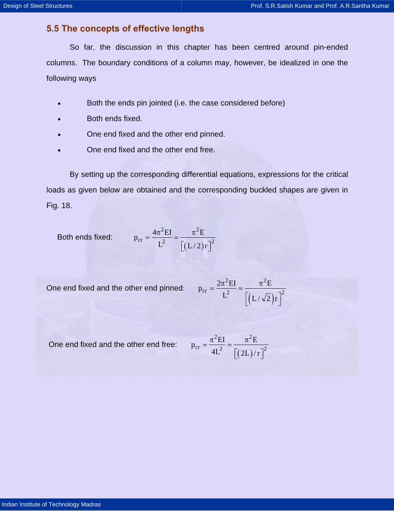
5.5 The concepts of effective lengths
So far, the discussion in this chapter has been centred around pin-ended
columns. The boundary conditions of a column may, however, be idealized in one the
following ways
• Both the ends pin jointed (i.e. the case considered before)
• Both ends fixed.
• One end fixed and the other end pinned.
• One end fixed and the other end free.
By setting up the corresponding differential equations, expressions for the critical
loads as given below are obtained and the corresponding buckled shapes are given in
Fig. 18.
Both ends fixed: ( )
2 2
cr 2 24 EI Ep
L L / 2 r
π π= =
⎡ ⎤⎣ ⎦
One end fixed and the other end pinned:
( )2 2
cr 2 22 EI Ep
L L / 2 r
π π= =
⎡ ⎤⎣ ⎦
One end fixed and the other end free: ( )
2 2
cr 2 2EI Ep
4L 2L / r
π π= =
⎡ ⎤⎣ ⎦
Design of Steel Structures Prof. S.R.Satish Kumar and Prof. A.R.Santha Kumar
Indian Institute of Technology Madras
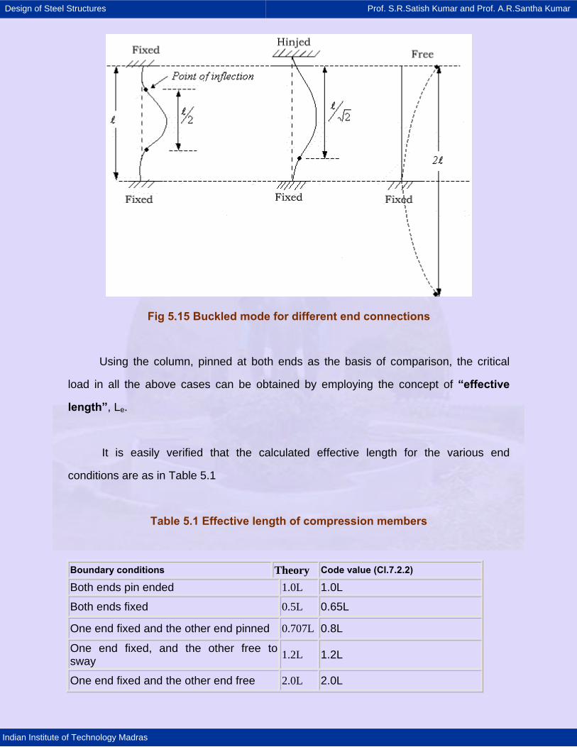
Fig 5.15 Buckled mode for different end connections
Using the column, pinned at both ends as the basis of comparison, the critical
load in all the above cases can be obtained by employing the concept of “effective
length”, Le.
It is easily verified that the calculated effective length for the various end
conditions are as in Table 5.1
Table 5.1 Effective length of compression members
Boundary conditions Theory Code value (Cl.7.2.2) Both ends pin ended 1.0L 1.0L
Both ends fixed 0.5L 0.65L
One end fixed and the other end pinned 0.707L 0.8L
One end fixed, and the other free to sway 1.2L 1.2L
One end fixed and the other end free 2.0L 2.0L
Design of Steel Structures Prof. S.R.Satish Kumar and Prof. A.R.Santha Kumar
Indian Institute of Technology Madras
It can be seen that the effective length corresponds to the distance between the
points of inflection in the buckled mode. The effective column length can be defined as
the length of an equivalent pin-ended column having the same load-carrying capacity as
the member under consideration. The smaller the effective length of a particular column,
the smaller its danger of lateral buckling and the greater its load carrying capacity. It
must be recognized that column ends in practice are neither perfectly fixed nor perfectly
hinged. The designer may have to interpolate between the theoretical values given
above, to obtain a sensible approximation to actual restraint conditions. Effective
lengths prescribed by the code are also given in Table 5.1.
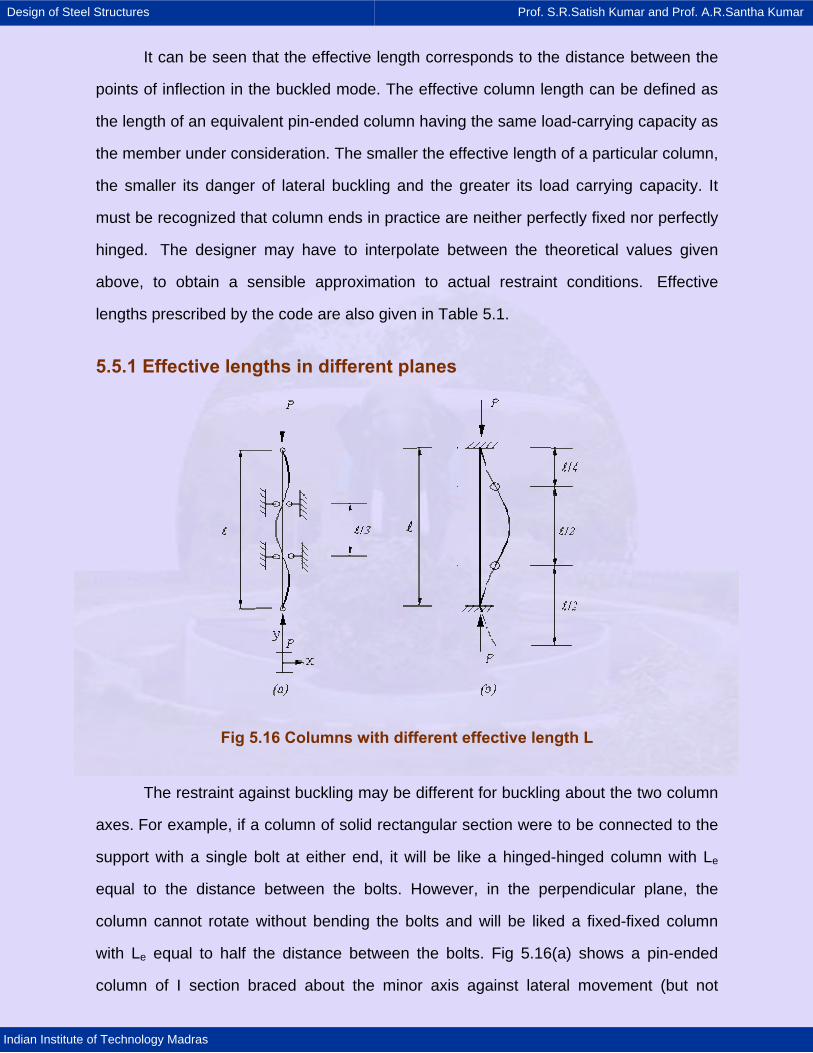
5.5.1 Effective lengths in different planes
Fig 5.16 Columns with different effective length L
The restraint against buckling may be different for buckling about the two column
axes. For example, if a column of solid rectangular section were to be connected to the
support with a single bolt at either end, it will be like a hinged-hinged column with Le
equal to the distance between the bolts. However, in the perpendicular plane, the
column cannot rotate without bending the bolts and will be liked a fixed-fixed column
with Le equal to half the distance between the bolts. Fig 5.16(a) shows a pin-ended
column of I section braced about the minor axis against lateral movement (but not
Design of Steel Structures Prof. S.R.Satish Kumar and Prof. A.R.Santha Kumar
Indian Institute of Technology Madras
rotationally restrained) at spacing L / 3. The minor axis buckling mode would be with an
effective pin-ended column length ( Le )y of L / 3. If there was no major axis bracing the
effective length for buckling about the major axis ( Le )x would remain as L. Therefore,
the design slenderness about the major and minor axis would be L / rx and ( L / 3 )ry,
respectively. Generally rx< 3ry for all I sections, hence the major axis slenderness ( L / rx
) would be greater, giving the lower value of critical load, and failure would occur by
major axis buckling. Anyway, checks should be carried out about both the axes.
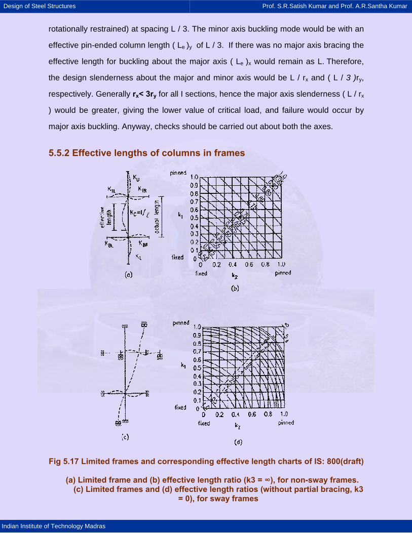
5.5.2 Effective lengths of columns in frames
Fig 5.17 Limited frames and corresponding effective length charts of IS: 800(draft)
(a) Limited frame and (b) effective length ratio (k3 = ∞), for non-sway frames. (c) Limited frames and (d) effective length ratios (without partial bracing, k3
= 0), for sway frames
Design of Steel Structures Prof. S.R.Satish Kumar and Prof. A.R.Santha Kumar
Indian Institute of Technology Madras
For compression members in rigid-jointed frames the effective length is directly
related to the restraint provided by all the surrounding members. In a frame the
interaction of all the members occurs because of the frame buckling as a whole rather
than column buckling. For individually design purposes, the behaviour of a limited
region of the frame is considered. The limited frame comprises the column under
consideration and each immediately adjacent member treated as if it were fixed at the
far end. The effective length of the critical column is then obtained from a chart which is
entered with two coefficients k1, and k2, the values of which depends upon the
stiffnesses of the surrounding members ku, kTL etc. Two different cases are considered
viz. columns in non-sway frames and columns in sway frames. All these cases as well
as effective length charts are shown in Fig.5.17. For the non-sway columns, the
effective lengths will vary from 0.5 to 1.0 depending on the values of k1 and k2, while for
the sway columns, the variation will be between 1.0 andα . These end points
correspond to cases of: (1) rotationally fixed ends with no sway and rotationally free
ends with no sway; (2) rotationally fixed ends with free sway and rotationally free ends
with free sway. The equations for calculating k1, and k2, are given in the code (Cl.7.2.2).
Design of Steel Structures Prof. S.R.Satish Kumar and Prof. A.R.Santha Kumar
Indian Institute of Technology Madras
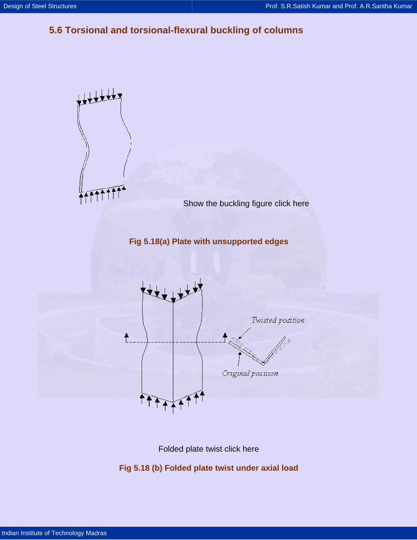
5.6 Torsional and torsional-flexural buckling of columns
Show the buckling figure click here
Fig 5.18(a) Plate with unsupported edges
Folded plate twist click here
Fig 5.18 (b) Folded plate twist under axial load
Design of Steel Structures Prof. S.R.Satish Kumar and Prof. A.R.Santha Kumar
Indian Institute of Technology Madras
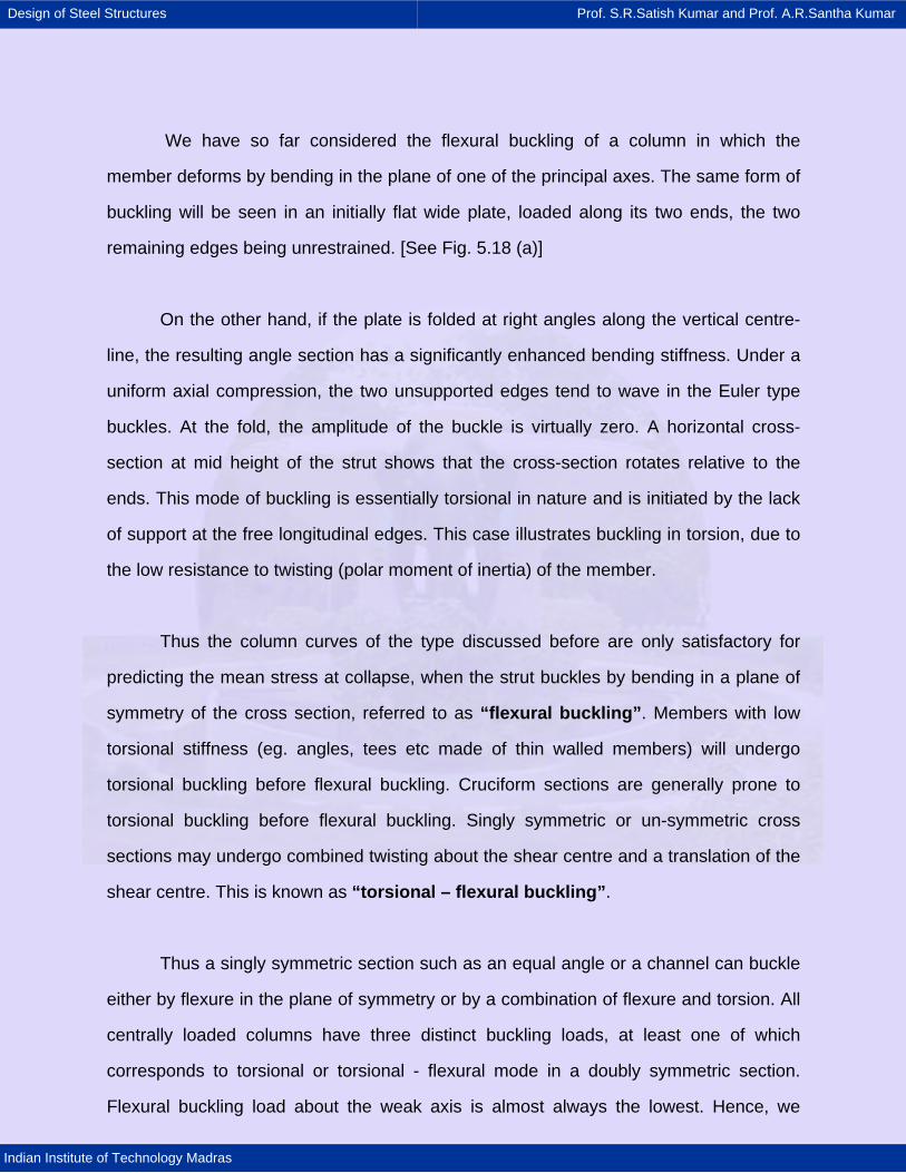
We have so far considered the flexural buckling of a column in which the
member deforms by bending in the plane of one of the principal axes. The same form of
buckling will be seen in an initially flat wide plate, loaded along its two ends, the two
remaining edges being unrestrained. [See Fig. 5.18 (a)]
On the other hand, if the plate is folded at right angles along the vertical centre-
line, the resulting angle section has a significantly enhanced bending stiffness. Under a
uniform axial compression, the two unsupported edges tend to wave in the Euler type
buckles. At the fold, the amplitude of the buckle is virtually zero. A horizontal cross-
section at mid height of the strut shows that the cross-section rotates relative to the
ends. This mode of buckling is essentially torsional in nature and is initiated by the lack
of support at the free longitudinal edges. This case illustrates buckling in torsion, due to
the low resistance to twisting (polar moment of inertia) of the member.
Thus the column curves of the type discussed before are only satisfactory for
predicting the mean stress at collapse, when the strut buckles by bending in a plane of
symmetry of the cross section, referred to as “flexural buckling”. Members with low
torsional stiffness (eg. angles, tees etc made of thin walled members) will undergo
torsional buckling before flexural buckling. Cruciform sections are generally prone to
torsional buckling before flexural buckling. Singly symmetric or un-symmetric cross
sections may undergo combined twisting about the shear centre and a translation of the
shear centre. This is known as “torsional – flexural buckling”.
Thus a singly symmetric section such as an equal angle or a channel can buckle
either by flexure in the plane of symmetry or by a combination of flexure and torsion. All
centrally loaded columns have three distinct buckling loads, at least one of which
corresponds to torsional or torsional - flexural mode in a doubly symmetric section.
Flexural buckling load about the weak axis is almost always the lowest. Hence, we
Design of Steel Structures Prof. S.R.Satish Kumar and Prof. A.R.Santha Kumar
Indian Institute of Technology Madras
disregard the torsional buckling load in doubly symmetric sections. In non-symmetric
sections, buckling will be always in torsional – flexural mode regardless of its shape and
dimensions. However, non-symmetric sections are rarely used.
Thin-walled open sections, such as angles and channels, can buckle by bending
or by a combination of bending and twisting. Which of these two modes is critical
depends on the shape and dimensions of the cross-section. Hence, torsional-flexural
buckling must be considered in their design. This is normally done by calculating an
equivalent slenderness ratio and using the same column strength curve as for flexural
buckling.
Design of Steel Structures Prof. S.R.Satish Kumar and Prof. A.R.Santha Kumar
Indian Institute of Technology Madras
5.7 Design strength Based on the studies of Ayrton & Perry (1886), the compressive strength of the
column can be obtained from the following equation.
( ) ( )y c e c e cf f f f .f .f− − = η (5.10)
Where, fy = yield stress, fc = compressive strength, fe = Euler buckling stress, λ =
Slenderness ratio (l/r) and η = a parameter allowing for the effects of lack of
straightness and eccentricity of loading and can be expressed as aλ where α is a
function of the shape of the cross section. Since Robertson evaluated the mean values
of α for many sections, the design method is termed "Perry-Robertson method".
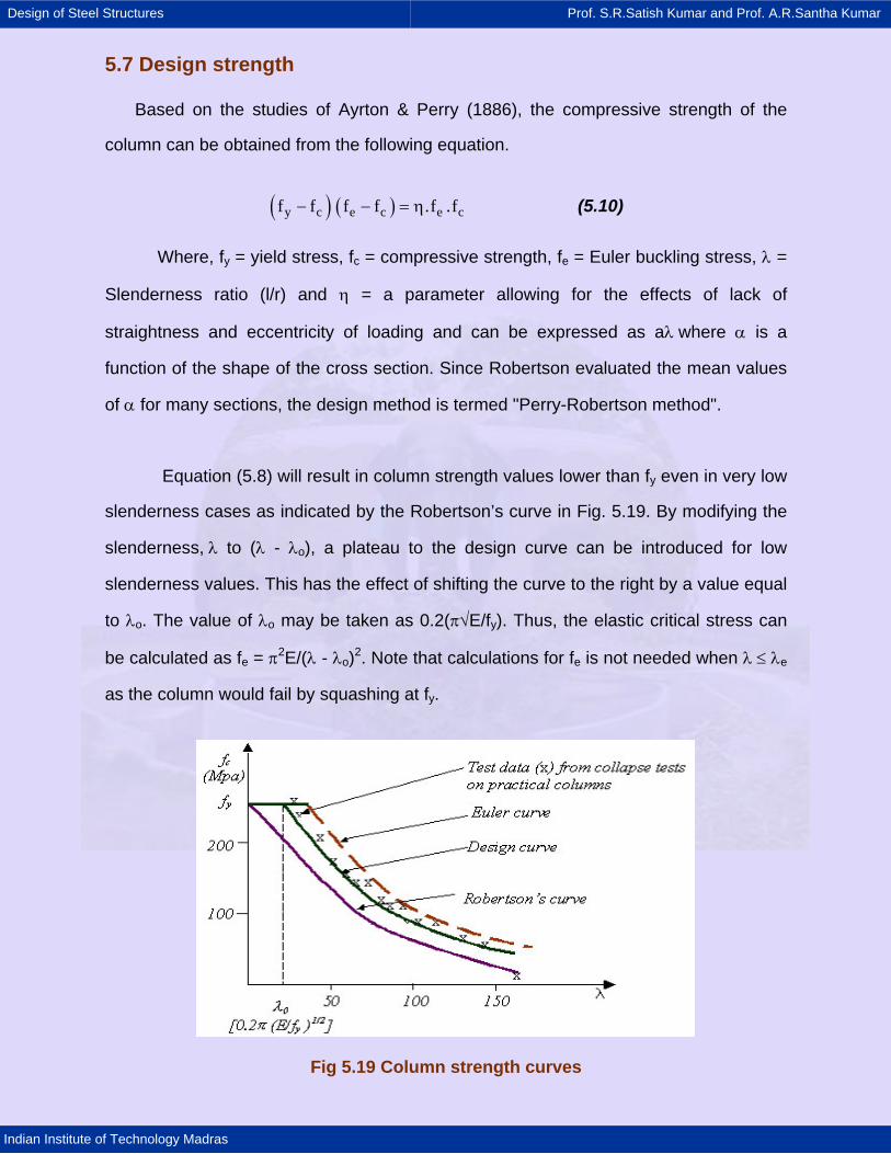
Equation (5.8) will result in column strength values lower than fy even in very low
slenderness cases as indicated by the Robertson’s curve in Fig. 5.19. By modifying the
slenderness, λ to (λ - λo), a plateau to the design curve can be introduced for low
slenderness values. This has the effect of shifting the curve to the right by a value equal
to λo. The value of λo may be taken as 0.2(π√E/fy). Thus, the elastic critical stress can
be calculated as fe = π2E/(λ - λo)2. Note that calculations for fe is not needed when λ ≤ λe
as the column would fail by squashing at fy.
Fig 5.19 Column strength curves
Design of Steel Structures Prof. S.R.Satish Kumar and Prof. A.R.Santha Kumar
Indian Institute of Technology Madras
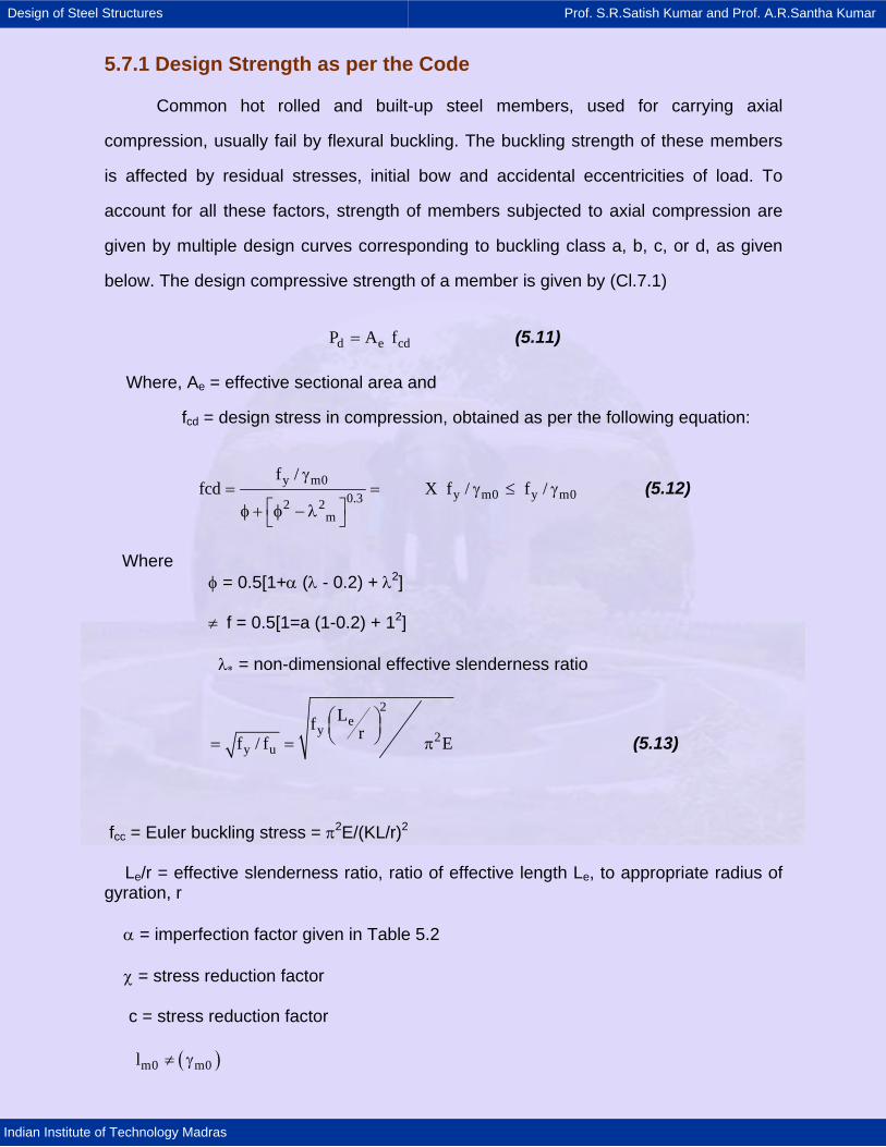
5.7.1 Design Strength as per the Code
Common hot rolled and built-up steel members, used for carrying axial
compression, usually fail by flexural buckling. The buckling strength of these members
is affected by residual stresses, initial bow and accidental eccentricities of load. To
account for all these factors, strength of members subjected to axial compression are
given by multiple design curves corresponding to buckling class a, b, c, or d, as given
below. The design compressive strength of a member is given by (Cl.7.1)
d e cdP A f= (5.11)
Where, Ae = effective sectional area and
fcd = design stress in compression, obtained as per the following equation:
y m0y m0 y m00.32 2
m
f /fcd X f / f /
γ= = γ ≤ γ
⎡ ⎤φ + φ − λ⎣ ⎦
(5.12)
Where φ = 0.5[1+α (λ - 0.2) + λ2]
≠ f = 0.5[1=a (1-0.2) + 12]
λ∗ = non-dimensional effective slenderness ratio
2e
y 2y u
Lf rf / f E⎛ ⎞⎜ ⎟⎝ ⎠= = π (5.13)
fcc = Euler buckling stress = π2E/(KL/r)2
Le/r = effective slenderness ratio, ratio of effective length Le, to appropriate radius of gyration, r
α = imperfection factor given in Table 5.2
χ = stress reduction factor
c = stress reduction factor
( )m0 m0l ≠ γ
Design of Steel Structures Prof. S.R.Satish Kumar and Prof. A.R.Santha Kumar
Indian Institute of Technology Madras
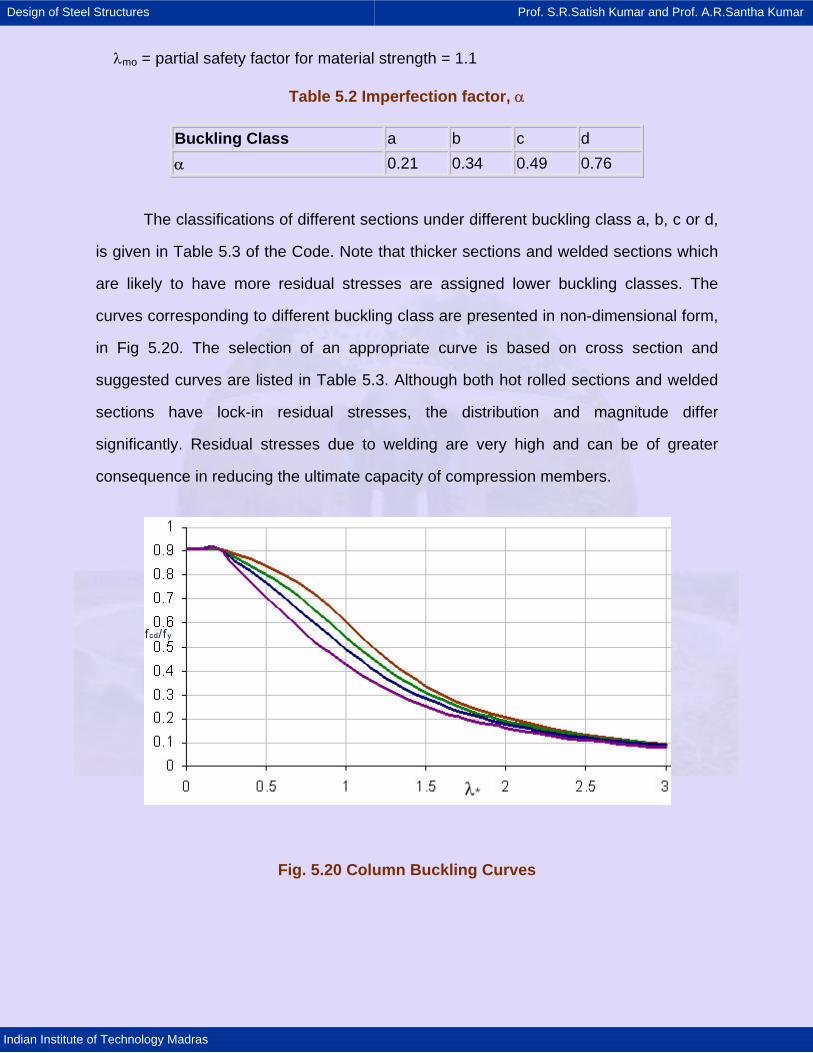
λmo = partial safety factor for material strength = 1.1
Table 5.2 Imperfection factor, α
Buckling Class a b c d α 0.21 0.34 0.49 0.76
The classifications of different sections under different buckling class a, b, c or d,
is given in Table 5.3 of the Code. Note that thicker sections and welded sections which
are likely to have more residual stresses are assigned lower buckling classes. The
curves corresponding to different buckling class are presented in non-dimensional form,
in Fig 5.20. The selection of an appropriate curve is based on cross section and
suggested curves are listed in Table 5.3. Although both hot rolled sections and welded
sections have lock-in residual stresses, the distribution and magnitude differ
significantly. Residual stresses due to welding are very high and can be of greater
consequence in reducing the ultimate capacity of compression members.
Fig. 5.20 Column Buckling Curves
Design of Steel Structures Prof. S.R.Satish Kumar and Prof. A.R.Santha Kumar
Indian Institute of Technology Madras
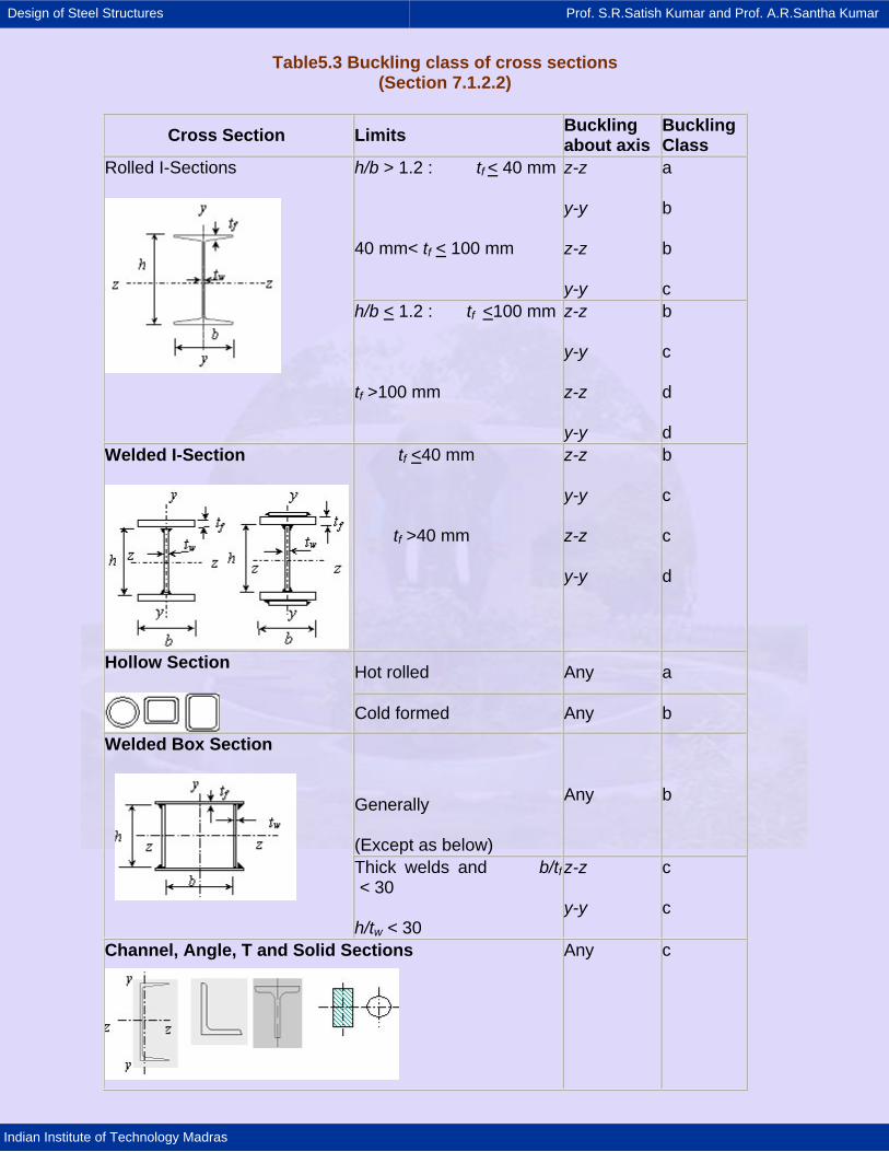
Table5.3 Buckling class of cross sections (Section 7.1.2.2)
Cross Section Limits Buckling about axis
Buckling Class
h/b > 1.2 : tf < 40 mm
40 mm< tf < 100 mm
z-z
y-y
z-z
y-y
a
b
b
c
Rolled I-Sections
h/b < 1.2 : tf <100 mm
tf >100 mm
z-z
y-y
z-z
y-y
b
c
d
d Welded I-Section
tf <40 mm
tf >40 mm
z-z
y-y
z-z
y-y
b
c
c
d
Hot rolled Any a Hollow Section
Cold formed Any b
Generally
(Except as below)
Any b
Welded Box Section
Thick welds and b/tf < 30
h/tw < 30
z-z
y-y
c
c
Channel, Angle, T and Solid Sections
Any c
Design of Steel Structures Prof. S.R.Satish Kumar and Prof. A.R.Santha Kumar
Indian Institute of Technology Madras
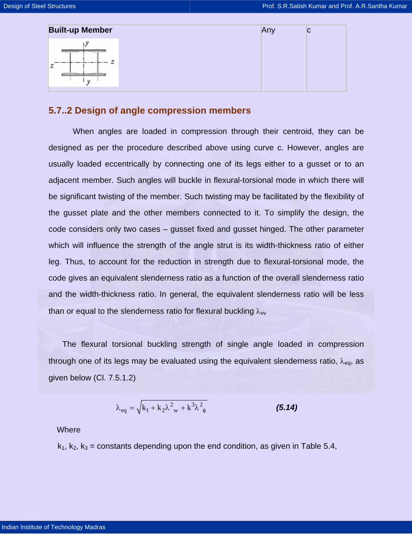
5.7..2 Design of angle compression members
When angles are loaded in compression through their centroid, they can be
designed as per the procedure described above using curve c. However, angles are
usually loaded eccentrically by connecting one of its legs either to a gusset or to an
adjacent member. Such angles will buckle in flexural-torsional mode in which there will
be significant twisting of the member. Such twisting may be facilitated by the flexibility of
the gusset plate and the other members connected to it. To simplify the design, the
code considers only two cases – gusset fixed and gusset hinged. The other parameter
which will influence the strength of the angle strut is its width-thickness ratio of either
leg. Thus, to account for the reduction in strength due to flexural-torsional mode, the
code gives an equivalent slenderness ratio as a function of the overall slenderness ratio
and the width-thickness ratio. In general, the equivalent slenderness ratio will be less
than or equal to the slenderness ratio for flexural buckling λvv
The flexural torsional buckling strength of single angle loaded in compression
through one of its legs may be evaluated using the equivalent slenderness ratio, λeq, as
given below (Cl. 7.5.1.2)
2 3 2eq 1 2 wk k k φλ = + λ + λ (5.14)
Where
k1, k2, k3 = constants depending upon the end condition, as given in Table 5.4,
Built-up Member
Any c
Design of Steel Structures Prof. S.R.Satish Kumar and Prof. A.R.Santha Kumar
Indian Institute of Technology Madras
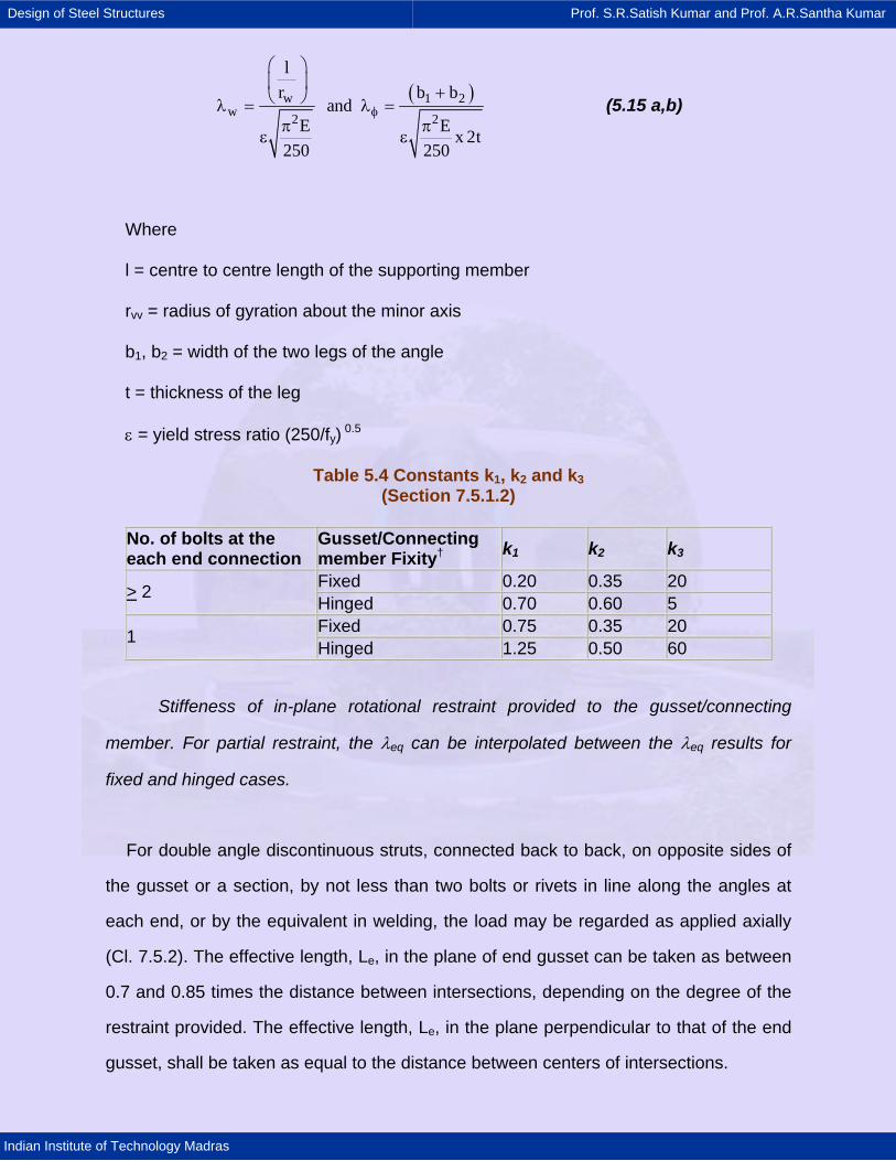
( )w 1 2w 2 2
lr b b
andE E x 2t
250 250
φ
⎛ ⎞⎜ ⎟ +⎝ ⎠λ = λ =
π πε ε
(5.15 a,b)
Where
l = centre to centre length of the supporting member
rvv = radius of gyration about the minor axis
b1, b2 = width of the two legs of the angle
t = thickness of the leg
ε = yield stress ratio (250/fy) 0.5
Table 5.4 Constants k1, k2 and k3 (Section 7.5.1.2)
No. of bolts at the each end connection
Gusset/Connecting member Fixity† k1 k2 k3
Fixed 0.20 0.35 20 > 2 Hinged 0.70 0.60 5 Fixed 0.75 0.35 20 1 Hinged 1.25 0.50 60
Stiffeness of in-plane rotational restraint provided to the gusset/connecting
member. For partial restraint, the λeq can be interpolated between the λeq results for
fixed and hinged cases.
For double angle discontinuous struts, connected back to back, on opposite sides of
the gusset or a section, by not less than two bolts or rivets in line along the angles at
each end, or by the equivalent in welding, the load may be regarded as applied axially
(Cl. 7.5.2). The effective length, Le, in the plane of end gusset can be taken as between
0.7 and 0.85 times the distance between intersections, depending on the degree of the
restraint provided. The effective length, Le, in the plane perpendicular to that of the end
gusset, shall be taken as equal to the distance between centers of intersections.
Design of Steel Structures Prof. S.R.Satish Kumar and Prof. A.R.Santha Kumar
Indian Institute of Technology Madras
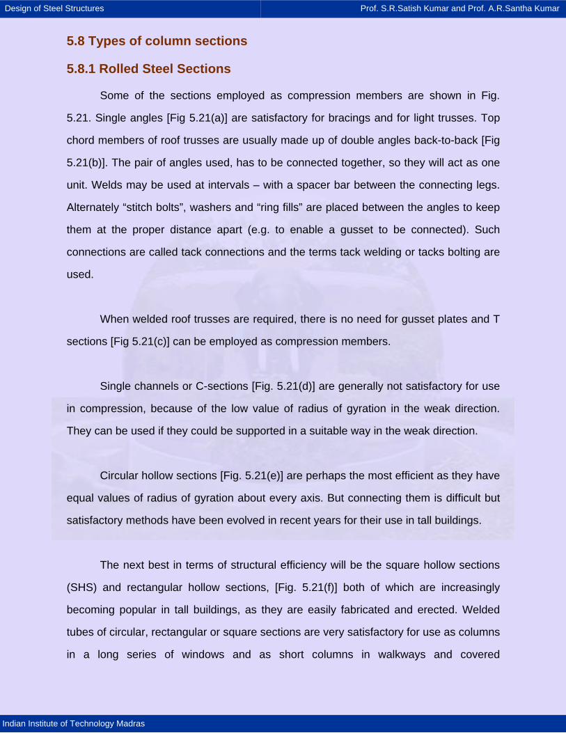
5.8 Types of column sections
5.8.1 Rolled Steel Sections
Some of the sections employed as compression members are shown in Fig.
5.21. Single angles [Fig 5.21(a)] are satisfactory for bracings and for light trusses. Top
chord members of roof trusses are usually made up of double angles back-to-back [Fig
5.21(b)]. The pair of angles used, has to be connected together, so they will act as one
unit. Welds may be used at intervals – with a spacer bar between the connecting legs.
Alternately “stitch bolts”, washers and “ring fills” are placed between the angles to keep
them at the proper distance apart (e.g. to enable a gusset to be connected). Such
connections are called tack connections and the terms tack welding or tacks bolting are
used.
When welded roof trusses are required, there is no need for gusset plates and T
sections [Fig 5.21(c)] can be employed as compression members.
Single channels or C-sections [Fig. 5.21(d)] are generally not satisfactory for use
in compression, because of the low value of radius of gyration in the weak direction.
They can be used if they could be supported in a suitable way in the weak direction.
Circular hollow sections [Fig. 5.21(e)] are perhaps the most efficient as they have
equal values of radius of gyration about every axis. But connecting them is difficult but
satisfactory methods have been evolved in recent years for their use in tall buildings.
The next best in terms of structural efficiency will be the square hollow sections
(SHS) and rectangular hollow sections, [Fig. 5.21(f)] both of which are increasingly
becoming popular in tall buildings, as they are easily fabricated and erected. Welded
tubes of circular, rectangular or square sections are very satisfactory for use as columns
in a long series of windows and as short columns in walkways and covered

Design of Steel Structures Prof. S.R.Satish Kumar and Prof. A.R.Santha Kumar
Indian Institute of Technology Madras
warehouses. For many structural applications the weight of hollow sections required
would be only 50% of that required for open profiles like I or C sections.
When the available sections are not suitable, a suitable section may be built-up
either by welding or by lacing or battening two sections separated by a suitable
distance.
Fig 5.21: Cross Section Shapes for Rolled Steel Compression Members
5.8.2 Built-up column or fabricated compression members
Compression members composed of two angles, channels, or tees back-to-back
in contact or separated by a small distance shall be connected together by tack riveting,
tack bolting or tack welding so that the individual sections do not buckle between the
tacks before the whole member buckles (Cl. 7.8). Special types of columns called Laced
and Battened columns are discussed later in this chapter.
When compression members are required for large structures like bridges, it will
be necessary to use built-up sections. They are particularly useful when loads are
heavy and members are long (e.g. top chords of Bridge Trusses). Built up sections
Design of Steel Structures Prof. S.R.Satish Kumar and Prof. A.R.Santha Kumar
Indian Institute of Technology Madras
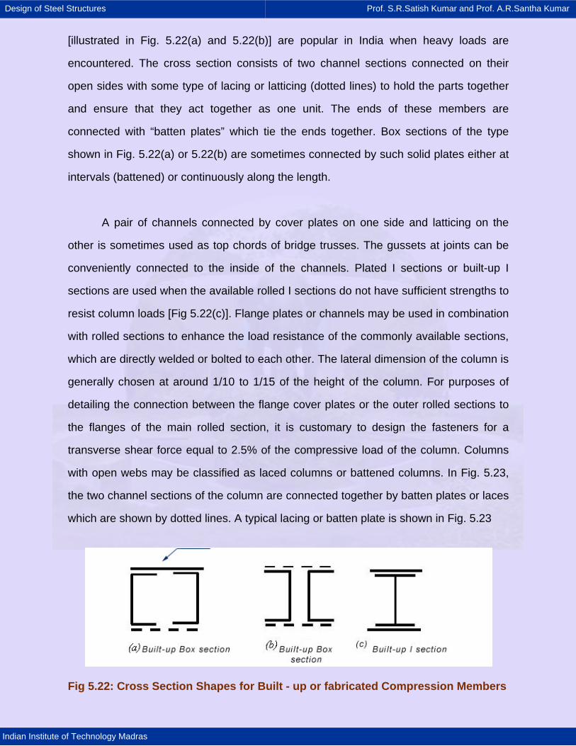
[illustrated in Fig. 5.22(a) and 5.22(b)] are popular in India when heavy loads are
encountered. The cross section consists of two channel sections connected on their
open sides with some type of lacing or latticing (dotted lines) to hold the parts together
and ensure that they act together as one unit. The ends of these members are
connected with “batten plates” which tie the ends together. Box sections of the type
shown in Fig. 5.22(a) or 5.22(b) are sometimes connected by such solid plates either at
intervals (battened) or continuously along the length.
A pair of channels connected by cover plates on one side and latticing on the
other is sometimes used as top chords of bridge trusses. The gussets at joints can be
conveniently connected to the inside of the channels. Plated I sections or built-up I
sections are used when the available rolled I sections do not have sufficient strengths to
resist column loads [Fig 5.22(c)]. Flange plates or channels may be used in combination
with rolled sections to enhance the load resistance of the commonly available sections,
which are directly welded or bolted to each other. The lateral dimension of the column is
generally chosen at around 1/10 to 1/15 of the height of the column. For purposes of
detailing the connection between the flange cover plates or the outer rolled sections to
the flanges of the main rolled section, it is customary to design the fasteners for a
transverse shear force equal to 2.5% of the compressive load of the column. Columns
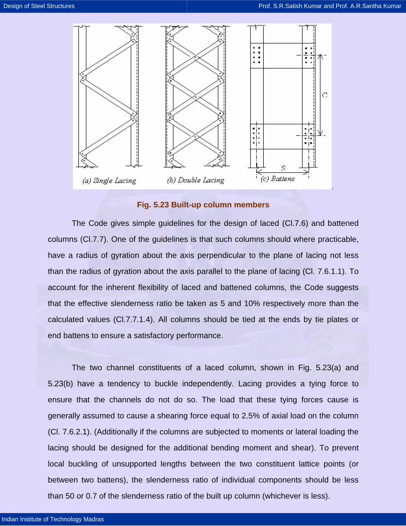
with open webs may be classified as laced columns or battened columns. In Fig. 5.23,
the two channel sections of the column are connected together by batten plates or laces
which are shown by dotted lines. A typical lacing or batten plate is shown in Fig. 5.23
Fig 5.22: Cross Section Shapes for Built - up or fabricated Compression Members
Design of Steel Structures Prof. S.R.Satish Kumar and Prof. A.R.Santha Kumar
Indian Institute of Technology Madras
.
Fig. 5.23 Built-up column members
The Code gives simple guidelines for the design of laced (Cl.7.6) and battened
columns (Cl.7.7). One of the guidelines is that such columns should where practicable,
have a radius of gyration about the axis perpendicular to the plane of lacing not less
than the radius of gyration about the axis parallel to the plane of lacing (Cl. 7.6.1.1). To
account for the inherent flexibility of laced and battened columns, the Code suggests
that the effective slenderness ratio be taken as 5 and 10% respectively more than the
calculated values (Cl.7.7.1.4). All columns should be tied at the ends by tie plates or
end battens to ensure a satisfactory performance.
The two channel constituents of a laced column, shown in Fig. 5.23(a) and
5.23(b) have a tendency to buckle independently. Lacing provides a tying force to
ensure that the channels do not do so. The load that these tying forces cause is
generally assumed to cause a shearing force equal to 2.5% of axial load on the column
(Cl. 7.6.2.1). (Additionally if the columns are subjected to moments or lateral loading the
lacing should be designed for the additional bending moment and shear). To prevent
local buckling of unsupported lengths between the two constituent lattice points (or
between two battens), the slenderness ratio of individual components should be less
than 50 or 0.7 of the slenderness ratio of the built up column (whichever is less).
Design of Steel Structures Prof. S.R.Satish Kumar and Prof. A.R.Santha Kumar
Indian Institute of Technology Madras
In laced columns, the lacing should be symmetrical in any two opposing faces to
avoid torsion. Lacings and battens are not combined in the same column. The
inclination of lacing bars from the axis of the column should not be less than 40o nor
more than 70o. (Cl. 7.6.5) The slenderness ratio of the lacing bars should not exceed
145 (Cl. 7.6.3). The effective length of lacing bars is the length between bolts for single
lacing and 0.7 of this length for double lacing. The width of the lacing bar should be at
least 3 times the diameter of the bolt (Cl. 7.6.3). Thickness of lacing bars should be at
least 1/40th of the length between bolts for single lacing and 1/60 of this length for
double lacing (both for welded and bolted connections) (Cl. 7.6.4).
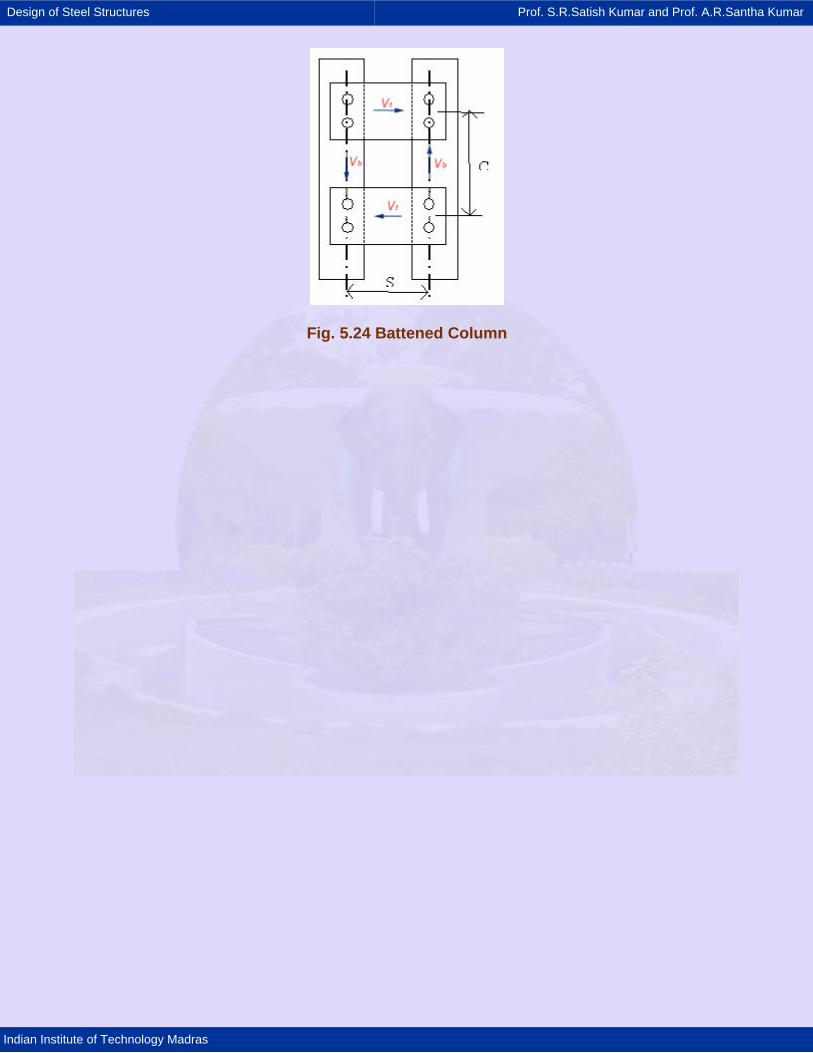
In battened columns, the Battens plates at their ends shall be riveted or welded
to the main components so as to resist simultaneously a shear Vb = Vt C/N S along the
column axis and a moment M = Vt C / 2 N at each connection (Cl.7.7). where, Vt = the
transverse shear force; C = the distance between centre-to-centre of battens,
longitudinally; N = the number of parallel planes of battens (usually 2); S = the minimum
transverse distance between the centroids of the bolt group/welding connecting the
batten to the main member.
When plates are used for battens, the end battens shall have an effective depth
not less than the perpendicular distance between the centroids of the main members.
The intermediate battens shall have an effective depth of not less than three quarters of
this distance, but in no case shall the effective depth of any batten be less than twice
the width of one member, in the plane of the battens. The thickness of batten or the tie
plates shall be not less than one fiftieth of the distance between the innermost
connecting lines of rivets or welds, perpendicular to the main member.
Design of Steel Structures Prof. S.R.Satish Kumar and Prof. A.R.Santha Kumar
Indian Institute of Technology Madras
Fig. 5.24 Battened Column
Design of Steel Structures Prof. S.R.Satish Kumar and Prof. A.R.Santha Kumar
Indian Institute of Technology Madras
5.9 Steps in the design of axially loaded columns
The procedure for the design of an axially compressed column is as follows:
(i) Assume a suitable trial section and classify the section in accordance with the
classification in chapter.
(ii) Arrive at the effective length of the column by suitably considering the end
conditions.
(iii) Calculate the slenderness ratios (λ values) in both minor and major axes
direction and also calculate λo using the formula given below:
0y
E0.2 fλ = π
(iv) Calculate fcd values along both major and minor axes from equation 12
(v) Compute the load that the compression member can resist (pd=Acfcd)
(vi) Calculate the factored applied load and check whether the column is safe
against the given loading. The most economical but safe section can be arrived at by
trial and error, i.e. repeating the above process.
The following values are suggested for initial choice of members:
(i) Single angle size: 1/30 of the length of the strut (L / r ~ 150)
(ii) Double angle size: 1/35 of the length of strut (L / r ~ 100-120)
(iii) Circular hollow sections diameter = 1/40 length (L / r ~ 100)